SpiderCloud Wireless RN310B2B5 SpiderCloud RadioNode SCRN-310-0205 User Manual 2
SpiderCloud Wireless SpiderCloud RadioNode SCRN-310-0205 2
Contents
- 1. User Manual 1
- 2. User Manual 2
User Manual 2
SpiderCloud Radio Node - SCRN-310 Hardware Installation Guide
SpiderCloud Wireless, Inc. 15
Figure 12 Fully Mounted
Installing the Radio Node (Method 2)
To route the cable directly and mount the radio node
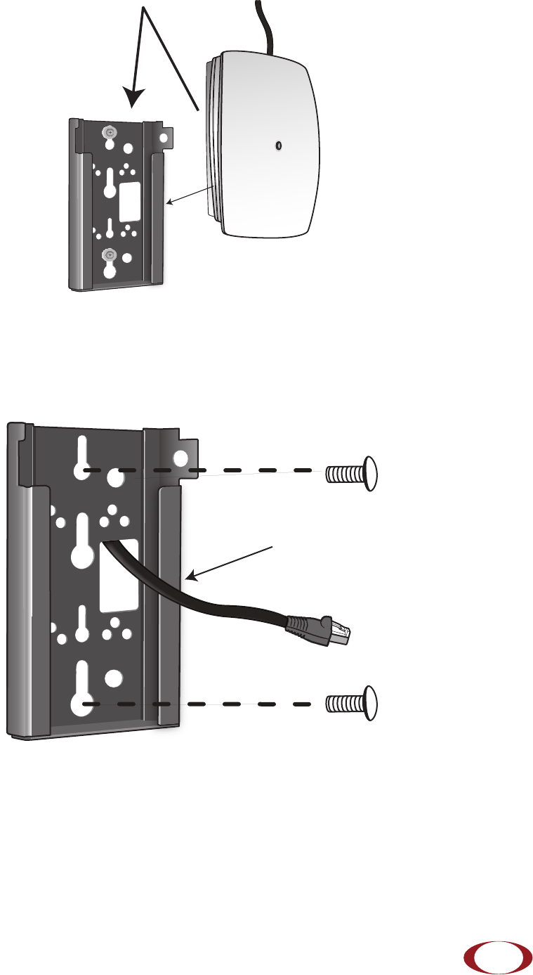
Step 1 Route the Ethernet cable through the large hole in the mounting bracket.
Figure 13 Mount Bracket with Direct Cable Routing
Step 2 With two user-provided screws, attach the mount bracket assembly to a wall or ceiling. The
screw holes are sized for an M4 (#10) screw. Ensure the screws have a snug fit onto the
studs, sheetrock, anchor, or other material you are bolting onto.
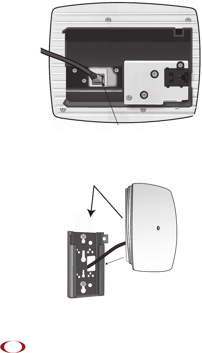
Step 3 Insert the RJ-45 connector into the Ethernet port as shown in Figure 14:
Transmit Side
SpiderCloud Radio Node - SCRN-310 Hardware Installation Guide
SpiderCloud Wireless, Inc.
16
Figure 14 Route and Terminate the Cable
Step 4 Push as much cable back through the wall or ceiling as possible. The mount bracket
assembly has room for some cable slack.
Step 5 Slide the pedestal base of the radio node into the groove opening in the mount bracket.
When the pedestal reaches the end of the trough, a spring clip will secure the unit into
place.
Figure 15 Fully Mounted
RJ-45 Connector in Ethernet Port
SpiderCloud Radio Node - SCRN-310 Hardware Installation Guide
SpiderCloud Wireless, Inc. 17
Completing the Installation
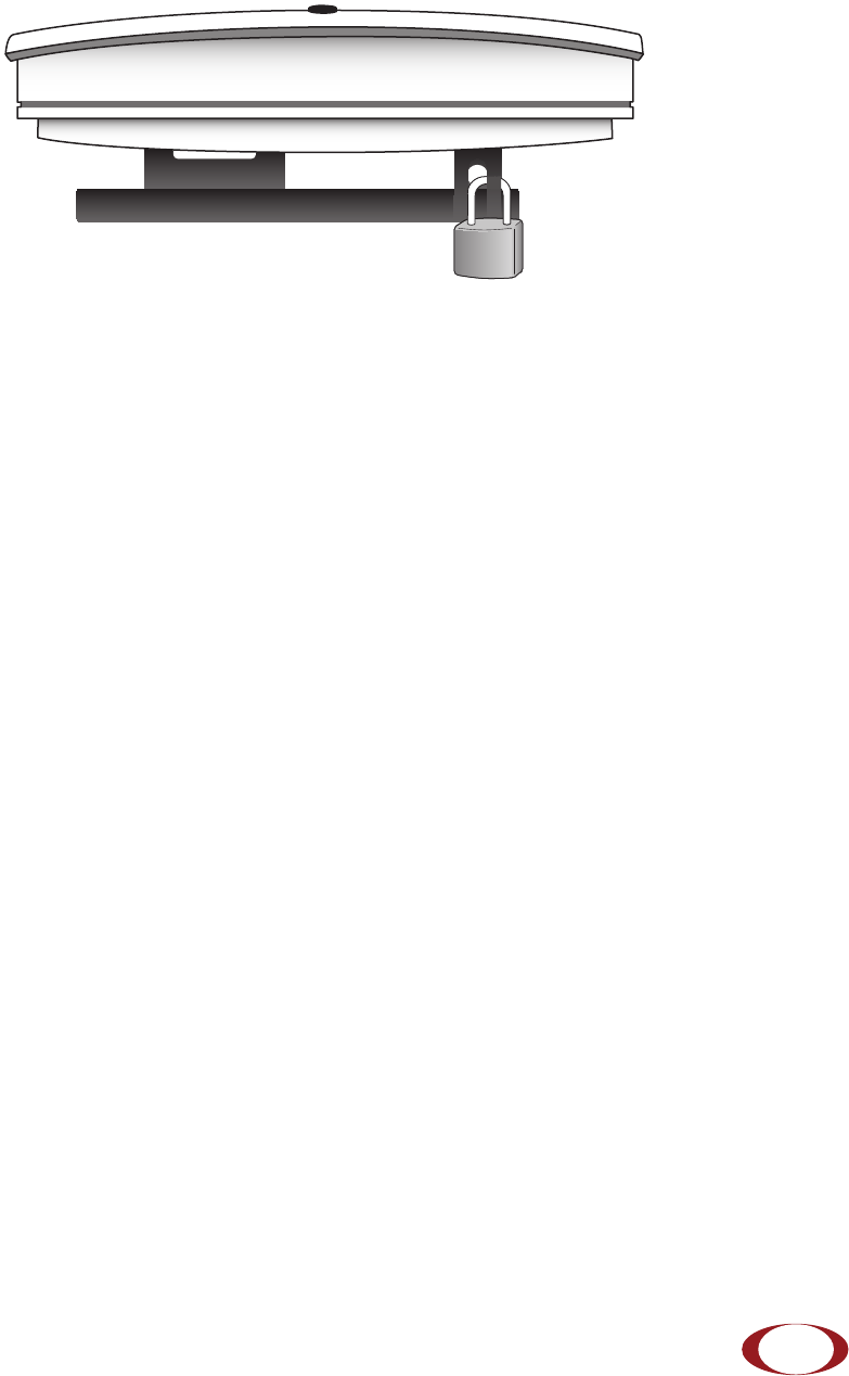
Step 1 Attach a padlock or cable tie wrap through the cutout lock holes in the mount bracket and
pedestal base.
Figure 16 Padlock and Lock Holes
The lock in the above figure is shown schematically. The orientation is for illustration purposes (not
accurate) since the bracket is typically wall or ceiling mounted.
Step 2 The radio node boots up and attempts to connect to the services node. Refer to Boot
Sequence and Services Node Communication on page 18 for more information.
Detaching the Radio Node from the Mount Bracket
To remove the radio node from the bracket assembly
Step 1 If needed, remove the padlock or cable tie wrap securing the radio node.
Step 2 Depress the spring clip on the pedestal base and slide the radio node out of the mount
bracket.
Step 3 Detach the RJ-45 clip from the Ethernet port and remove the cable from cable brackets
and cable opening.
SpiderCloud Radio Node - SCRN-310 Hardware Installation Guide
SpiderCloud Wireless, Inc.
18
Boot Sequence and Services Node Communication
On initial boot, the radio node performs the following boot sequence and communicates with the services
node. It performs this boot sequence twice, first for the UMTS subsystem, then again for the LTE
subsystem. This sequence takes about one minute to complete for each subsystem. When finished, all
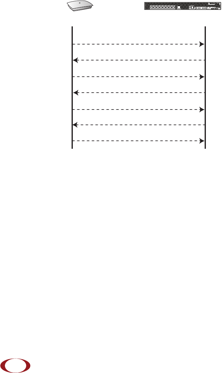
devices are reachable. Figure 17 shows the radio node boot sequence:
Figure 17 Radio Node Boot Sequence
UMTS Sequence Description:
1. When the radio node is powered on, the device sends a DHCP Request to the services node
DHCP server to get IP information. The DHCP server is configured on the services node to
respond only to DHCP requests from SpiderCloud Wireless radio nodes. Refer to the SpiderCloud
OS (SCOS) Administrator Guide for more information about the services node DHCP server
configuration.
2. The server responds with the IP addresses of the radio node and the services node (the master of
the radio node).
3. Using its own IP address, the radio node sends a Join Request message to the services node. The
radio node seeks to join the cellular network.
4. The services node responds with a Join Response message indicating whether the radio node is
allowed to join the network or not.
5. The arrival sequence begins. Based on the configuration of the radio node, the radio node will join
the system and get its configuration. The services node sends the SpiderCloud software image
(the system image and configuration settings) to the radio node.
6. The radio node reboots and mounts the SpiderCloud software image as a RAM-based file system.
7. The radio node contacts the services node and joins the network.
USB CONSOLE
LK AT LK AT LK AT LK AT LK AT LK AT LK AT LK AT
81234567
LNK ACT
MGMT
POWER STATUS 1 2
SIM 0 SIM 1
Radio Node Services Node
DHCP Request for IP Address
DHCP Response (RN, IP, Controller IP)
Join Request
Join Response (Join Grant, Redirect, Denied)
Arrival sequence begins
Send SpiderCloud software package
Mount package, join the network

SpiderCloud Radio Node - SCRN-310 Hardware Installation Guide
SpiderCloud Wireless, Inc. 19
Radio Node LED Boot Sequence
The radio node state machine is sequential and progresses in the following order:
State 0 -> State 1 -> State 2 -> State 3 -> State 4 -> State 5
A normal boot sequence transitions through all these states sequentially and the LED state transitions
accordingly. If the radio node fails to transition to the next state, the system restarts the boot sequence,
starting with State 0. You can determine the progress during the booting stages by observing the LED color
transitions. On failure, the last LED state will display the state that encountered the failure. Tab le 3 shows
the radio node boot sequence and corresponding LED behavior:
Table 3: Radio Node LED Boot Sequence
State LED Color Description Possible Failures and Actions
0. Power On/
Reset
Flashing
Green
This is the initial state on startup.
The radio node bootup is controlled by
firmware in this state.
It will go through a lamp test in this
state. A lamp test involves cycling
through all LED colors.
This state should be very short
lived and should transition to the
next state immediately.
A radio node should not stay in
this state indefinitely.
Note: Flashing Green is also
used to indicate a radio node
that has been administratively
disabled. This can be
determined from the CLI.
1. DHCP Solid
Red
The radio node starts by sending out a
DHCP Request.
The radio node moves to the next state
(State 2) upon receiving a DHCP
response and an IP Address.
No DHCP Response, IP
Address not allocated.
Check cabling, DHCP Server
configuration.
2. Join Solid
Blue
The radio node has an IP Address and
sends a UDP Join request to the
Serving services node.
The radio node moves to the next state
(State 3) upon getting a JOIN GRANT
from the services node.
No IP reachability to the
services node.
Check IP network between
radio node and services node
for routing issues.

SpiderCloud Radio Node - SCRN-310 Hardware Installation Guide
SpiderCloud Wireless, Inc.
20
Radio Node LED Management
The LED display is active by default, but can be deactivated in light-sensitive environments as needed.
Even when the display is disabled, the LED will be lighted during the following conditions:
• while the radio node is booting
• if the radio node or cell is in fault state
• if there is an active emergency call
• if the locate radio node feature is active
• if the follow IMSI feature is active
Tabl e 4 shows the default LED behavior of the radio node:
3. TFTP Flashing
Blue
The radio node proceeds next to
download the operating system image
from the services node.
The radio node moves to the next state
(State 4) after the image has been
downloaded.
Failure to download TFTP
image.
Check firewall between radio
node and services node.
4. Operating
System Booting
Flashing
Green
The radio node loads the operating
system and starts the default platform
applications.
The radio node moves to the next state
(State 5) when it establishes
connectivity with the service node.
Failure to start the operating
system.
This normally points to a
software/build issue. Please
contact SpiderCloud support.
5. Running Solid
Green
The operating system is running. The
radio node continues the startup
sequence, but is now controlled by the
services node.
The operating system is up and
running on the radio node.
Any subsequent state
transitions can now be tracked
from events and logs on the
services node.
Table 4: Radio Node LED Behavior
LED Status Flash Rate
Green: slow flashing Administratively disabled Approximately ½ second on, 1½ sec. off
Green: fast flashing Booting Approximately 1.4 second on/off cycle
Green: solid Operational
Red: solid Fault
Red: fast flashing One or more emergency calls active Approximately 1 second on/off cycle
Table 3: Radio Node LED Boot Sequence (continued)
State LED Color Description Possible Failures and Actions

SpiderCloud Radio Node - SCRN-310 Hardware Installation Guide
SpiderCloud Wireless, Inc. 21
* Refer to the SpiderCloud OS (SCOS) Administrator Guide for information about the locate radio node
and follow IMSI features.
To disable the LED display
Step 1 From the Configuration Mode, issue the set System RadioNode LED DefaultMode
Dark command to disable the LED display:
set System RadioNode LED DefaultMode Dark
Step 2 Issue the show System RadioNode LED command to verify the configuration:
show System RadioNode LED
DefaultMode Dark;
To re-enable the LED display
Step 1 From the Configuration Mode, issue the set System RadioNode LED DefaultMode
Standard command to re-enable the LED display:
set System RadioNode LED DefaultMode Standard
Step 2 Issue the show System RadioNode LED command to verify the configuration:
show System RadioNode LED
DefaultMode Standard;
Blue: fast flashing Locate radio node enabled* Approximately 1 second on/off cycle
Blue: solid Follow IMSI enabled*
Off Powered off or LED disabled
Table 4: Radio Node LED Behavior (continued)
LED Status Flash Rate

SpiderCloud Radio Node - SCRN-310 Hardware Installation Guide
SpiderCloud Wireless, Inc.
22
The SpiderCloud Documentation Set
The SpiderCloud documentation set includes:
•The SpiderCloud System Description provides an overview of how the SpiderCloud system fits
within an operator’s network and in an enterprise, describes key features of the system, and
provides specifications for the services and radio nodes.
•The SpiderCloud Feature Description high-level descriptions of the E-RAN system features,
their impact on the product components (services nodes and radio nodes), manageability
considerations, and feature benefits.
•The SpiderCloud OS (SCOS) Administrator Guide provides procedures for configuring the
software environment and internetworking between the services node and radio node devices.
•The SpiderCloud Services Node Hardware Installation Guide provides hardware specifications
and installation instructions.
•The SpiderCloud Radio Node Hardware Installation Guide provides hardware specifications and
installation instructions.
•The E-RAN Deployment Planning Guide provides information about planning and dimensioning
E-RAN systems.
•The SpiderCloud OS (SCOS) CLI User Guide provides an introduction to the key features and
functionalities of the SpiderCloud Command Line Interface (CLI).
•The SCOS NB Data Model Reference Guide provides details about the objects and parameters
that comprise the system configuration and operational state.
•The SpiderCloud OS Faults, Conditions, and Events Reference Guide provides details about all
system faults, conditions, and events.
•The SpiderCloud System Commissioning Guide provides information about turning up a
SpiderCloud E-RAN with the Local Configuration Interface (LCI) graphical user interface.
•The Performance Measurements for SpiderCloud Small-Cell E-RAN provides a reference guide
to Key Performance Indicators (KPI) that monitor the health and state of the E-RAN system.
•The E-RAN Troubleshooting Guide provides information about diagnosing and correcting
problems with installing, provisioning, administering, and maintaining SpiderCloud equipment
and services.
•The SpiderNet Management System Installation and Administration Guide provides information
about installing the SpiderNet network management server and client and using it to remotely
manage E-RAN deployments.
•The SpiderCloud Time Zone Reference Guide provides the information required to configure the
time zone for SpiderCloud services nodes.
SpiderCloud Wireless, Inc. 23
SpiderCloud Radio Node - SCRN-310 Hardware Installation Guide
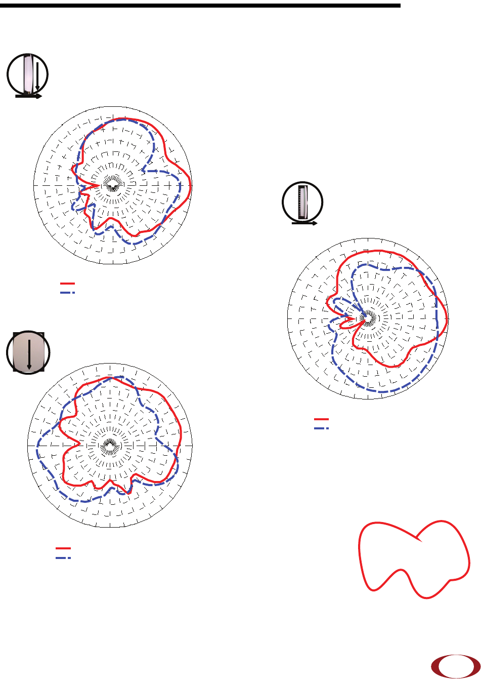
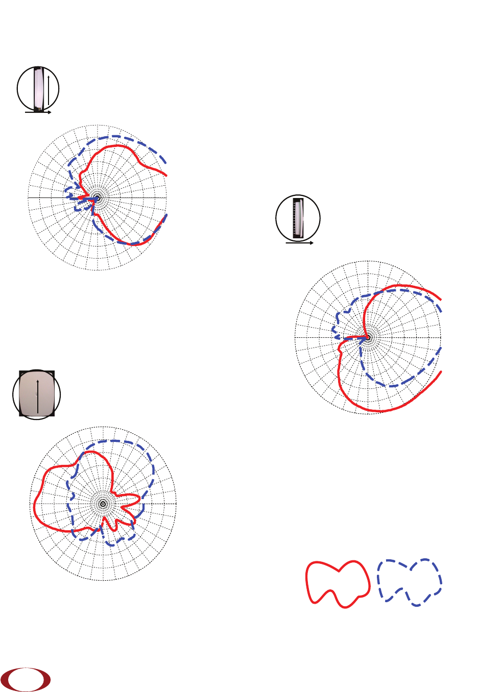
Appendix A: UMTS Antenna Patterns
UMTS Band Antenna Patterns
0º
90º
Front
EL2 Cut (Side-to-Side)
90º
0º
Up
0º
Front
90º
Up
AZ Cut
EL1Cut (Front-to-Back) -15
-15
-12
-12
-9
-9
-6
-6
-3
-3
0
0
3 dB
3 dB
0
o
30
o
60
o
90
o
120
o
150
o
180
o
-150
o
-120
o
-90
o
-60
o
-30
o
AUT
1
@ 2140 MHz : Max Gain
1
= 2. 59 dB i at 3
o
AUT
2
@ 2140 MHz : Max Gain
2
= 2. 04 dB i at -6 3
o
-15
-15
-12
-12
-9
-9
-6
-6
-3
-3
0
0
3 dB
3 dB
90
o
60
o
30
o
0
o
-30
o
-60
o
-90
o
-120
o
-150
o
180
o
150
o
120
o
AUT
1
= 2140 MHz : M ax G ain
1
= 2. 59 dB i a t 90
o
AUT
2
= 2140 MHz : M ax G ain
2
= -0 .08 dB i at 93
o
-15
-15
-12
-12
-9
-9
-6
-6
-3
-3
0
0
3 dB
3 dB
90o
60o
30o
0o
-30o
-60o
-90o
-120o
-150o
180o
150o
120o
AUT
1
= 2140 MHz : Max Gain
1
= 0.61 dBi at 75
o
AUT
2
= 2140 MHz : Max Gain
2
= 0.69 dBi at -96
o
Transmit Antenna
SpiderCloud Radio Node - SCRN-310 Hardware Installation Guide
SpiderCloud Wireless, Inc.
24
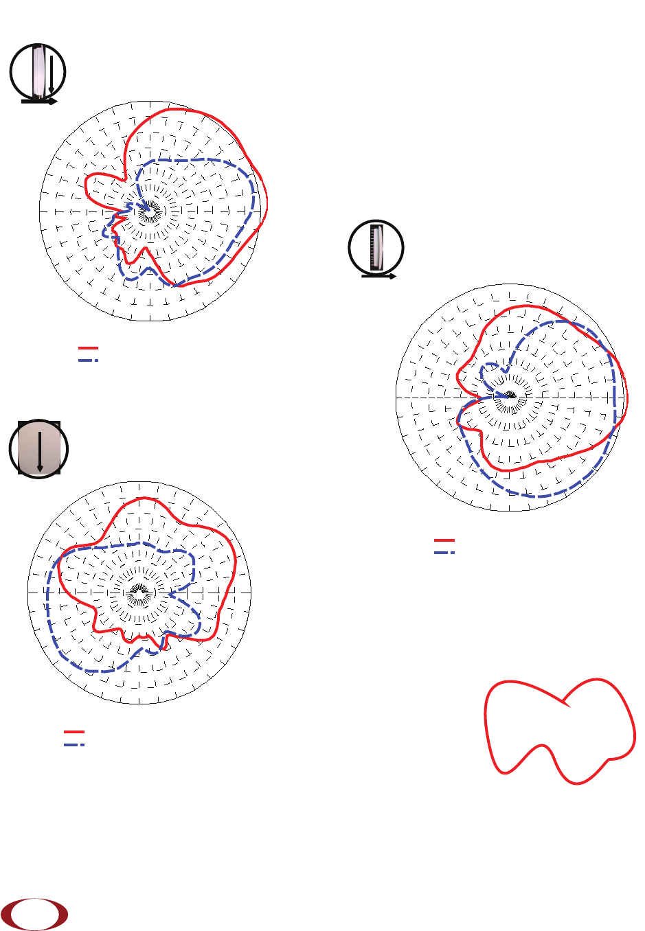
PCS Band Antenna Patterns
EL1 Cut (Front-to-Back)
EL2 Cut (Side-to-Side)
AZ Cut
0º
90º
Front
Transmit Antenna
-15
-15
-12
-12
-9
-9
-6
-6
-3
-3
0
0
3 dB
3 dB
0o
30o
60o
90o
120o
150o
180o
-150o
-120o
-90o
-60o
-30 o
AUT
1
@ 19 60 M H z : Max Gain
1
= 4.1 dBi at 3
o
AUT
2
@ 19 60 M H z : Max Gain
2
= 2.33 dBi at -36
o
-15
-15
-12
-12
-9
-9
-6
-6
-3
-3
0
0
3 dB
3 dB
90
o
60
o
30
o
0
o
-30
o
-60
o
-90
o
-120
o
-150
o
180
o
150
o
120
o
AUT
1 = 1960 MHz : Max Gain1 = 4. 43 d B i at 84o
AUT
2 = 1960 MHz : Max Gain2 = 2 dBi at 78o
-15
-15
-12
-12
-9
-9
-6
-6
-3
-3
0
0
3 dB
3 dB
90o
60o
30o
0o
-30o
-60o
-90o
-120o
-150o
180o
150o
120o
AUT
1
= 19 60 MHz : M a x Gai n
1
= 1. 49 dB i a t 63
o
AUT
2
= 19 60 MHz : M a x Gai n
2
= 0. 64 dB i a t -129
o
90º
0º
Up
0º
Front
90º
Up
SpiderCloud Radio Node - SCRN-310 Hardware Installation Guide
SpiderCloud Wireless, Inc. 25
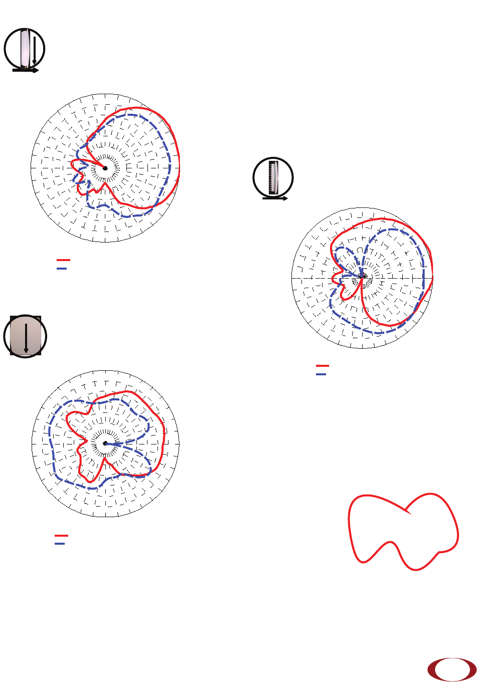
Transmit Antenna
AZ Cut
0º
90º
Front
90º
0º
Up
EL2 Cut (Side-to-Side)
0º
Front
90º
Up
EL1 Cut (Front-to-Back)
DCS Band Antenna Patterns
-15
-15
-12
-12
-9
-9
-6
-6
-3
-3
0
0
3 dB
3 dB
90
o
60
o
30
o
0
o
-30
o
-60
o
-90
o
-120
o
-150
o
180
o
150
o
120
o
AUT
1
= 18 44 MHz : Ma x Ga i n
1
= 3.55 dBi at 54
o
AUT
2
= 18 44 MHz : Ma x Ga i n
2
= 0.42 dBi at 84
o
-15
-15
-12
-12
-9
-9
-6
-6
-3
-3
0
0
3 dB
3 dB
90
o
60
o
30
o
0
o
-30
o
-60
o
-90
o
-120
o
-150
o
180
o
150
o
120
o
AUT
1
= 1844 MHz : Max Gain
1
= -0.73 dBi at 72
o
AUT
2
= 1844 MHz : Max Gain
2
= -1.27 dBi at -123
o
-15
-15
-12
-12
-9
-9
-6
-6
-3
-3
0
0
3 dB
3 dB
0o
30o
60o
90o
120o
150o
180o
-150o
-120o
-90o
-60o
-30 o
AUT
1 @ 1844 MHz : Max Gain1
= 3. 53 dBi at 24o
AUT
2 @ 1844 MHz : Max Gain2
= 0. 9 dB i at 39o

SpiderCloud Radio Node - SCRN-310 Hardware Installation Guide
SpiderCloud Wireless, Inc.
26
SpiderCloud Wireless, Inc. 27
SpiderCloud Radio Node - SCRN-310 Hardware Installation Guide
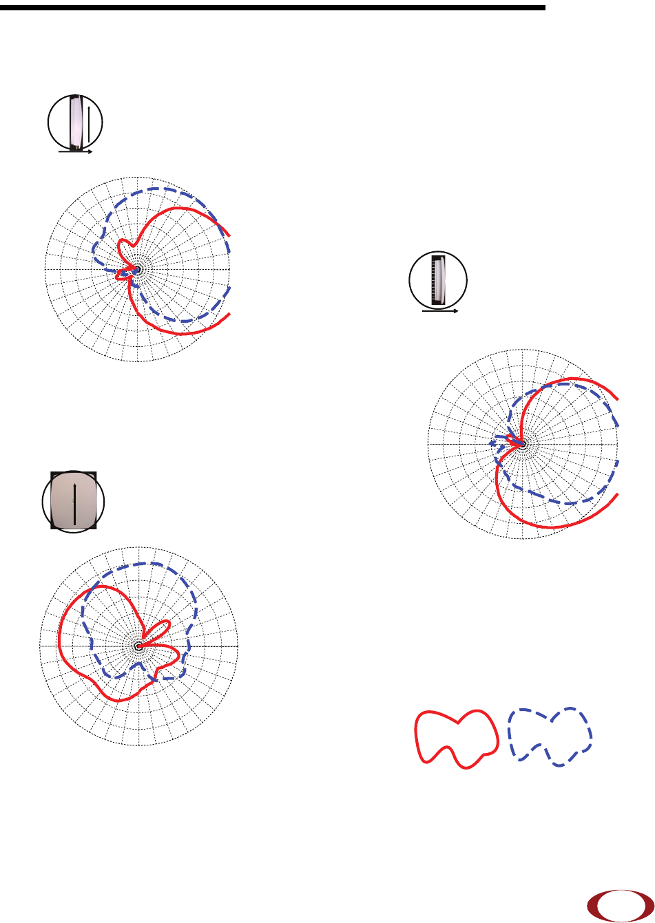
Appendix B: LTE Antenna Patterns
LTE Band 4 Antenna Patterns
-12
-12
-9
-9
-6
-6
-3
-3
0
0
3 dB
3 dB
0
o
30o
60o
90o
120o
150o
180o
-150o
-120o
-90o
-60o
-30o
AZ Cut
-12
-12
-9
-9
-6
-6
-3
-3
0
0
3 dB
3 dB
90
o
60
o
30
o
0
o
-30
o
-60
o
-90
o
-120
o
-150
o
180
o
150
o
120
o
EL1 Cut (Front-to-Back)
EL2 Cut (Side-to-Side)
-12
-12
-9
-9
-6
-6
-3
-3
0
0
3 dB
3 dB
90o
60o
30o
0o
-30o
-60o
-90o
-120o
-150o
180o
150o
120o
LTE Antenna 1 LTE Antenna 2
0º
Front
90º
Up
0º
90º
Front
Top
90º
0º
Up
SpiderCloud Radio Node - SCRN-310 Hardware Installation Guide
SpiderCloud Wireless, Inc.
28
LTE Band 7 Antenna Patterns
AZ Cut
EL1 Cut (Front-to-Back)
EL2 Cut (Side-to-Side)
-12
-12
-9
-9
-6
-6
-3
-3
0
0
3 dB
3 dB
0o
30o
60o
90
120o
150o
180o
-150o
-120o
-90o
-60o
-30o
-12
-12
-9
-9
-6
-6
-3
-3
0
0
3 dB
3 dB
90
o
60
o
30
o
0
o
-30
o
-60
o
-90
o
-120
o
-150
o
180
o
150
o
120
o
-12
-12
-9
-9
-6
-6
-3
-3
0
0
3 dB
3 dB
90
o
60
o
30
o
0
o
-30
o
-60
o
-90
o
-120
o
-150
o
180
o
150
o
120
o
LTE Antenna 1 LTE Antenna 2
0º
90º
Front
Top
0º
Front
90º
Up
90º
0º
Up