SpiderCloud Wireless RN320B446 SpiderCloud Radio Node User Manual Installation Manual 1

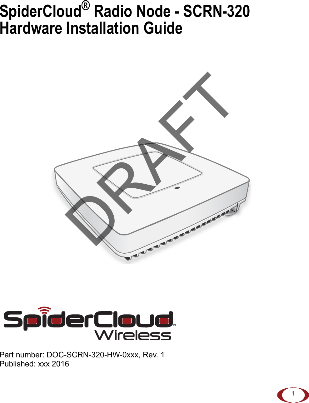
SpiderCloud Wireless SpiderCloud Radio Node Installation Manual 1
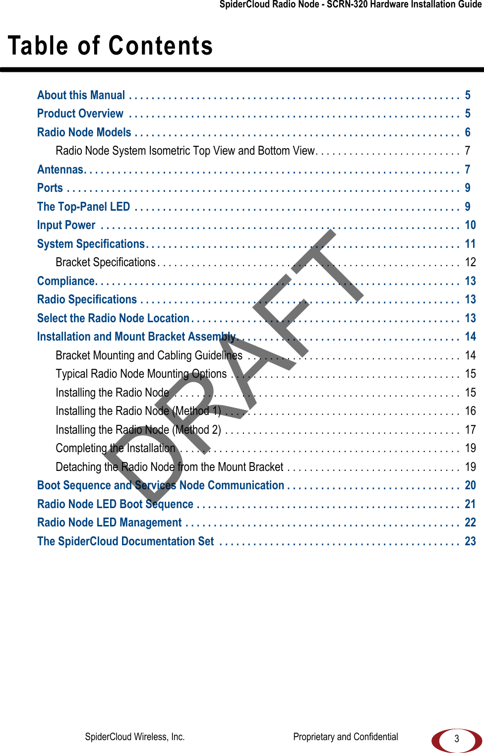
Contents

Installation Manual 1

1SpiderCloud® Radio Node - SCRN-320 Hardware Installation GuidePart number: DOC-SCRN-320-HW-0xxx, Rev. 1Published: xxx 2016®DRAFT
2FCC StatementsCaution: Any changes or modification cautions to this device not explicitly approved by manufacturer could void your authority to operate this equipment.This equipment complies with FCC radiation exposure limits set forth for an uncontrolled environment. This equipment should be installed and operated with minimum 25 cm between the radiator and your body. This transmitter must not be collocated or operating in conjunction with any other antenna or transmitter unless authorized to do so by the FCC.Legal NoticeCustomer agrees that the Software, including the specific design and structure of individual programs, and the Documentation are protected by United States and foreign copyright and trade secret laws. Customer agrees not to reproduce, disclose, alter, provide or otherwise make available such trade secrets or copyrighted material in any form to any third party without the prior written consent of SpiderCloud Wireless. Customer agrees to implement reasonable security measures to protect such trade secrets and copyrighted material at least to the extent that Customer protects its own information of a similar nature.The information contained herein is subject to change without notice. Although all information is believed to be accurate at the date of publication, SpiderCloud assumes no responsibility for inaccuracies contained herein. Copyright © 2016 SpiderCloud Wireless, Inc. SpiderCloud Wireless is a registered trademark and SmartCloud a trademark of SpiderCloud Wireless, Inc. All rights reserved.SpiderCloud Wireless475 Sycamore DriveMilpitas, CA 95035, USAhttp://www.spidercloud.comTel: +1 408 235-2900Email: info@spidercloud.comRevision HistoryRevision Date Summary of Changes1 xxx Initial document releaseDRAFTSpiderCloud Wireless, Inc.                                              Proprietary and Confidential
  SpiderCloud Radio Node - SCRN-320 Hardware Installation Guide3 Table of ContentsAbout this Manual . . . . . . . . . . . . . . . . . . . . . . . . . . . . . . . . . . . . . . . . . . . . . . . . . . . . . . . . . . .  5Product Overview  . . . . . . . . . . . . . . . . . . . . . . . . . . . . . . . . . . . . . . . . . . . . . . . . . . . . . . . . . . .  5Radio Node Models . . . . . . . . . . . . . . . . . . . . . . . . . . . . . . . . . . . . . . . . . . . . . . . . . . . . . . . . . .  6Radio Node System Isometric Top View and Bottom View. . . . . . . . . . . . . . . . . . . . . . . . . .  7Antennas. . . . . . . . . . . . . . . . . . . . . . . . . . . . . . . . . . . . . . . . . . . . . . . . . . . . . . . . . . . . . . . . . . .  7Ports . . . . . . . . . . . . . . . . . . . . . . . . . . . . . . . . . . . . . . . . . . . . . . . . . . . . . . . . . . . . . . . . . . . . . .  9The Top-Panel LED  . . . . . . . . . . . . . . . . . . . . . . . . . . . . . . . . . . . . . . . . . . . . . . . . . . . . . . . . . .  9Input Power  . . . . . . . . . . . . . . . . . . . . . . . . . . . . . . . . . . . . . . . . . . . . . . . . . . . . . . . . . . . . . . . .  10System Specifications. . . . . . . . . . . . . . . . . . . . . . . . . . . . . . . . . . . . . . . . . . . . . . . . . . . . . . . .  11Bracket Specifications . . . . . . . . . . . . . . . . . . . . . . . . . . . . . . . . . . . . . . . . . . . . . . . . . . . . . .  12Compliance. . . . . . . . . . . . . . . . . . . . . . . . . . . . . . . . . . . . . . . . . . . . . . . . . . . . . . . . . . . . . . . . .  13Radio Specifications . . . . . . . . . . . . . . . . . . . . . . . . . . . . . . . . . . . . . . . . . . . . . . . . . . . . . . . . .  13Select the Radio Node Location . . . . . . . . . . . . . . . . . . . . . . . . . . . . . . . . . . . . . . . . . . . . . . . .  13Installation and Mount Bracket Assembly. . . . . . . . . . . . . . . . . . . . . . . . . . . . . . . . . . . . . . . .  14Bracket Mounting and Cabling Guidelines  . . . . . . . . . . . . . . . . . . . . . . . . . . . . . . . . . . . . . .  14Typical Radio Node Mounting Options . . . . . . . . . . . . . . . . . . . . . . . . . . . . . . . . . . . . . . . . .  15Installing the Radio Node  . . . . . . . . . . . . . . . . . . . . . . . . . . . . . . . . . . . . . . . . . . . . . . . . . . . 15Installing the Radio Node (Method 1) . . . . . . . . . . . . . . . . . . . . . . . . . . . . . . . . . . . . . . . . . .  16Installing the Radio Node (Method 2) . . . . . . . . . . . . . . . . . . . . . . . . . . . . . . . . . . . . . . . . . .  17Completing the Installation  . . . . . . . . . . . . . . . . . . . . . . . . . . . . . . . . . . . . . . . . . . . . . . . . . . 19Detaching the Radio Node from the Mount Bracket . . . . . . . . . . . . . . . . . . . . . . . . . . . . . . .  19Boot Sequence and Services Node Communication . . . . . . . . . . . . . . . . . . . . . . . . . . . . . . .  20Radio Node LED Boot Sequence . . . . . . . . . . . . . . . . . . . . . . . . . . . . . . . . . . . . . . . . . . . . . . .  21Radio Node LED Management . . . . . . . . . . . . . . . . . . . . . . . . . . . . . . . . . . . . . . . . . . . . . . . . .  22The SpiderCloud Documentation Set  . . . . . . . . . . . . . . . . . . . . . . . . . . . . . . . . . . . . . . . . . . .  23DRAFTSpiderCloud Wireless, Inc.                                              Proprietary and Confidential
  Contents 4DRAFTSpiderCloud Wireless, Inc.                                              Proprietary and Confidential
5SpiderCloud Radio Node - SCRN-320 Hardware Installation GuideAbout this ManualThis guide provides the system specifications of the SpiderCloud Wireless® Radio Node 320 (SCRN-320). It includes detailed hardware installation instructions, the boot sequence, and expected LED behavior both during the boot-up and under operating conditions. An appendix shows the radio node antenna patterns. The primary audience for this guide includes network planners, system administrators and installation personnel. It assumes you have knowledge about networking principles, networking configuration, site preparation, powering, and experience in hardware installation and maintenance.Product OverviewThe SCRN-320 is an LTE-U and LTE-LAA capable small cell that operates in a licensed LTE frequency carrier, aggregated with license-exempt 5GHz spectrum, to deliver higher capacity and enhanced user experience without the need for new network elements or complexity.SpiderCloud’s scalable small cell system, called an Enterprise Radio Access Network (E-RAN), hides the complexity of radio management and mobility and provides operators with a single touch-point to aggregate and manage a large network of LTE small cells. The SCRN-320 builds upon the LTE-Advanced functionalities of the E-RAN system and leverages CA and Self Organizing Networks (SON) capabilities to support LTE-U and LTE-LAA operation.Each SCRN-320 radio node supports a licensed LTE carrier paired with a supplemental downlink 5GHz carrier operating in UNII-1 (5150-5250MHz) or UNII-3 (5725-5850MHz) bands. Both licensed and unlicensed radios support 2x2 MIMO operation enabling higher user capacity and average data rates per radio node coverage footprint. When the unlicensed channel is paired with a 20 MHz licensed LTE channel, each SCRN-320 supports a peak downlink rate of 300 Mbps and a peak uplink rate of 50 Mbps. The SCRN-320 is easy to install and connects to the existing enterprise LAN using standard Ethernet cabling or to a dedicated LAN infrastructure deployed for use by the operator. SCRN-320 radio node are managed by the SpiderCloud SCSN-9000 services node installed in the enterprise or in a centralized location such as a data center. The SCRN-320 has no fans and is convection cooled. Antennas are built-in with an orderable option for SMA connectors for use with external antennas.The SCRN-320 utilizes on-chip Trusted Platform Module (TPM) functions to implement secure boot, and establish certificate-based IPsec tunnel to SpiderCloud services node for all traffic. There is no management or console port on the radio node. The radio node can be physically locked to prevent theft.Figure 1 on page 6 shows the logical architecture of the SCRN-320 in the network: DRAFTSpiderCloud Wireless, Inc.                                              Proprietary and Confidential
SpiderCloud Radio Node - SCRN-320 Hardware Installation Guide 6 Figure 1 Radio Node Relationship to Enterprise and Mobile Operator Core NetworksRadio Node ModelsTabl e 1  displays the orderable configuration of the SCRN-320 radio node:Table 1: SCRN-320 Radio Node ConfigurationsRadio Node Model DescriptionSCRN-320-02UL LTE Band 2 with license-exempt Band 252 or 255SCRN-320-04UL LTE Band 4 with license-exempt Band 252 or 255LAN IntranetDMZEnterpriseMobile Operator CoreEmail WebRadio NodesIPsecBackhaulIPsecCoreSwitchFirewall SecurityGatewayIPsecSGWMMELTES1-CS1-ULTES1PoE+SwitchPoE+SwitchServices NodeGNSS AntennaDRAFTSpiderCloud Wireless, Inc.                                              Proprietary and Confidential
SpiderCloud Radio Node - SCRN-320 Hardware Installation Guide7Radio Node System Isometric Top View and Bottom ViewThe following drawings display an isometric top and bottom views of the radio node: Figure 2 Radio Node Top ViewFigure 3 Radio Node Bottom ViewAntennasThe radio node includes four internal Tx/Rx antennas with a peak gain of 5dBi and operates in 2x2 mode with MIMO or four optional ports with SubMinature version A (SMA) coaxial connectors for external DRAFTSpiderCloud Wireless, Inc.                                              Proprietary and Confidential
SpiderCloud Radio Node - SCRN-320 Hardware Installation Guide 8antennas. Both models contain one internal network listen antenna. Figure 4 shows the radio node coaxial connectors: Figure 4 External Antenna Ports Figure 5 shows the location of the licenced and unlicensed LTE antennas: Figure 5 External Antenna Band LocationsUnlicenced LTEUnlicenced LTELicenced LTELicenced LTEInternalSnifferAntennaDRAFTSpiderCloud Wireless, Inc.                                              Proprietary and Confidential
SpiderCloud Radio Node - SCRN-320 Hardware Installation Guide9Ports The radio node has one 1 Gigabit Ethernet port that supports a Category 5e (Cat 5e) or better twisted-pair cable with an RJ-45 connector. Figure 6 shows the Ethernet port. There are two LEDs on the connector:•Link: Steady green state indicates a normal Layer 2 link connection has been established. •Activity: Yellow blinking indicates data activity.  Figure 6 Ethernet PortThe Top-Panel LEDThe radio node has one top-panel tricolor (RGB) LED to indicate power and status. This is the only LED visible under normal operating conditions. When the radio node initially boots the LED cycles through a number of colors and flashing behaviors until it is fully operational. Status indications: boot, normal, disabled, fault, emergency call, radio node tracking.  Figure 7 Radio Node Tricolor LEDEthernetPortLink ActivityLEDDRAFTSpiderCloud Wireless, Inc.                                              Proprietary and Confidential
SpiderCloud Radio Node - SCRN-320 Hardware Installation Guide 10Input PowerThe radio node receives its power from a standard Power Over Ethernet (PoE+) switch (typical) or injector. The radio node is fully compliant with the IEEE 802.3at PoE+ specification.Per IEEE 802.3at, use standard Cat 5e or better twisted-pair cable with a maximum length restriction of 100 meters (328 feet) for PoE+. This restriction minimizes power loss between the PoE+ power source and the radio node. When connecting the radio node to a PoE+ switch, ensure that the switch port is statically configured to deliver minimum 25W of power. Figure 8 shows the valid radio node cabling/powering options: Figure 8 Valid Radio Node Cabling/Powering OptionsPower is distributed over two pairs of the four available pairs in Cat 5e or better cables. The radio node can accept power on either used or un-used pairs.Some PoE switches may be factory configured to deliver lower power per port. If this is the case change the configuration during installation.NoteNoteServices NodePoE+ SwitchOutIn Services NodePoE+ Switch orPoE+ InjectorPoE+ InjectorNon PoE+ SwitchDRAFTSpiderCloud Wireless, Inc.                                              Proprietary and Confidential
SpiderCloud Radio Node - SCRN-320 Hardware Installation Guide11The illustration below shows a generic single-port PoE+ injector. Use this injector only when a PoE+ Ethernet switch is not available. Figure 9 Typical PoE+ InjectorTo connect the PoE+ injector to a radio nodeStep 1  Attach the injector power cord to a power source.Step 2  Connect an unpowered Ethernet cable from a switch to the IN port on the injector. Step 3  Connect an Ethernet cable from the injector’s OUT port to the radio node. The injector will now inject power onto a pair of wire pairs in the cable. The radio node will expect a nominal 48V DC input (57V max) from a typical PoE+ injector.System SpecificationsThe SCRN-310 radio node has the following chassis measurements, power requirements, and environmental requirements, and complies with the following standards. Refer to the feature guide for your services node software release for release-specific features and specifications. Table 2: Radio Node Specifications Dimensions Height:1.82 cm (7.2 in.)Width: 1.82 cm (7.2 in.)Depth: 4.4 cm (1.7 in.)Weight 1.13 kg. (2.5 lbs)Active Sessions per Radio NodeUp to 64 active LTE usersPeak Data Rate Downlink 300 Mbps; Uplink 50 Mbps (at 20 MHz)Voice Services VoLTE; 4 data bearers per UEPower RequirementsLicensed: Maximum transmit power: 2x125 mW (24 dBm)Unlicensed: Maximum transmit power: 2x250 mW (27 dBm)Input Power Power over Ethernet (PoE+) draws approximately 18WChannel Size Licensed: 5, 10, 15, 20 MHzUnlicensed: 20 MHzOUT INCONNECT PoEPLUS ONDRAFTSpiderCloud Wireless, Inc.                                              Proprietary and Confidential
SpiderCloud Radio Node - SCRN-320 Hardware Installation Guide 12Bracket SpecificationsThe SCRN-310 radio node connects to one of two brackets for ceiling or wall mounting:• a quarter-inch (0.64 centimeter) deep for cabling through a surface such as a wall or ceiling• a 1.25 inch (3.18 centimeters) deep for exposed cabling along a hard surface such as brick or cinder blockTabl e 3  shows the specification for these brackets:  Environmental RequirementsOperating temperature range: 0o to 40oC (32o to 104oF)Non-operating temperature range: 0 to 85oC (32 to 185oF)Relative humidity: Operating and storage: 0% RH to 90% RH non-condensingIngress protection rating: IP30Physical Interfaces1 x Gigabit Ethernet 1000 Base-T with an RJ-45 connectorLEDs 1 top-panel tricolor (RGB) LED to indicate power and statusMounting Wall, Ceiling, PlenumAntenna  Four internal Tx/RX antennas that operate in 2x2 mode with MIMOOne internal network listen antennaSynchronization PTP based frequency synchronization to services nodeCellular network listen for phase synchronization to LTE macro eNodeBsMTBF TBDTable 3: Radio Node Specifications 0.25-Inch BracketDimensions Height:1.57 cm (6.2 in.)Width: 1.3 cm (5.1 in.)Depth: 0.64 cm (0.25 in.)Weight 0.17 kg. (5.8 oz)1.25-Inch BracketDimensions Height:1.57 cm (6.2 in.)Width: 1.3 cm (5.1 in.)Depth: 3.18 cm (1.25 in.)Weight 0.24 kg. (8.2 oz)Table 2: Radio Node Specifications  (continued)DRAFTSpiderCloud Wireless, Inc.                                              Proprietary and Confidential
SpiderCloud Radio Node - SCRN-320 Hardware Installation Guide13ComplianceThe SCRN-320 complies with the following standards: Radio SpecificationsThe SCRN-310 has the following variants: Select the Radio Node LocationRadio nodes can be installed in a wide range of locations including walls, ceilings, and spaces above the ceiling. Follow the installation guidelines for selecting appropriate mounting locations for the unit. When mounting a radio node vertically, align the bottom-side fins vertically for superior cooling. Refer to the E-RAN Deployment Planning Guide for information about mounting positioning and the affects on cellular coverage. Always consult local codes about mounting and wiring SpiderCloud Wireless equipment.Table 4: SCRN-320 Compliance Safety EN 60950-160950CB certification (IEC 60950, UL 60950-1)EMC/Radio(FCC) FCC Part 15B (Class A)FCC Part 24FCC Part 27RoHS Directive 2011/65/EUTable 5: Radio Node Specifications RadioNodeModel Operating Mode Network Listen BandsMaximum Transmit Power (per Band)SCRN-320-02UL Band 2 LTE, Band 252 or 255 unlicensedLTE 2100/1900/700 MHz 5 GHz2 x 21 dBm LTE licensed band2 x 24 dBm 5GHz unlicensed bandSCRN-320-04UL Band 4 LTE, Band 252 or 255 unlicensedLTE 2100/1900/700 MHz 2 x 21 dBm LTE licensed band2 x 24 dBm 5GHz unlicensed bandDRAFTSpiderCloud Wireless, Inc.                                              Proprietary and Confidential
SpiderCloud Radio Node - SCRN-320 Hardware Installation Guide 14 Figure 10 Radio Node LocationsWhen possible, locate radio node units at least 6 meters (20 feet) from an external wall. This distance maximizes indoor coverage and minimizes RF leakage outside the building. Refer to the E-RAN Deployment Planning Guide for Dual-Mode Systems and E-RAN Deployment Planning Guide for LTE Systems for more information about radio node placement.When mounting near a wall or other obstruction, orient the mounting bracket such that the transmit antenna faces towards the coverage area and faces away from the wall. Refer to  Bracket Mounting and Cabling Guidelines on page 14 for more information.Installation and Mount Bracket AssemblyThe radio node slides into one of two brackets for ceiling or wall mounting:• a quarter-inch (0.64 centimeter) deep for cabling through a surface such as a wall or ceiling• a 1.25 inch (3.18 centimeters) deep for exposed cabling along a hard surface such as brick or cinder blockBracket Mounting and Cabling GuidelinesIncorrectly cabling and mounting a radio node can result in crushed cables and loss of communications to the unit. Follow these guidelines in cabling the radio node and mounting it on the bracket:• Ensure that the cabling is properly routed and dressed. • Ensure that the radio node is fully inserted into the mount bracket so that it locks into place and is flush. A correctly installed cable should at no time during installation impede inserting the radio node into the mount bracket. • Secure the radio node to the mount bracket with a padlock or tie wrap to provide physical security.Dead / Non-CirculatingAirspaceLiving / Working Space of a TypicalCommercial BuildingDrop CeilingWallForced-Air SupplyForced-Air ReturnXXDRAFTSpiderCloud Wireless, Inc.                                              Proprietary and Confidential
SpiderCloud Radio Node - SCRN-320 Hardware Installation Guide15• When mounting the radio node vertically, orient the bracket such that the bracket keyholes have the narrow side up as shown in Figure 11.Typical Radio Node Mounting OptionsRadio nodes can be mounted on a wide number of surfaces including the following typical surfaces:•Light grill: Use bolts, nuts, and washers to secure the universal mount bracket using holes in the light grill. Adjust the universal mounting bracket until the bracket and light grill holes align.•Directly on the wall or ceiling: Use drywall screws to secure the universal mount bracket directly to sheetrock or plasterboard on the wall or ceiling.•Mud or plaster ring: Secure the universal mount bracket directly on the wall or ceiling as above with a 3 1/4 inch (8.25 centimeter) mud or plaster ring between the mount bracket and the mounting service and run the Ethernet cable through ring’s hole. •Existing infrastructure: Secure the universal mount bracket to existing infrastructure as long as the radio node RF propagation or existing installed equipment is not adversely impacted.•Non-metal tiles: Use bracing for rear support and mount the radio node in the center of the tile for even weight distribution. Ensure that the bracing is the same width as the tile. •Drop ceiling: Contact your SpiderCloud Wireless representative for recommendations of supported third-party brackets and clamps.Installing the Radio NodeThe radio node receives its power source over powered Ethernet. If your wiring closet does not have existing PoE+ equipment, SpiderCloud Wireless recommends a PoE+ power injector for the radio node. See section  Input Power on page 10.The Ethernet cable can directly through a surface such as a wall or ceiling or route the cable openly:• Refer to Installing the Radio Node (Method 1) on page 16 for direct cable routing installation through an opening behind the mount bracket using the shorter mount bracket.• Refer to Installing the Radio Node (Method 2) on page 17 for open cable routing installation using the taller mount bracket.DRAFTSpiderCloud Wireless, Inc.                                              Proprietary and Confidential

Navigation menu