SpiderCloud Wireless RN320B446 SpiderCloud Radio Node User Manual
SpiderCloud Wireless SpiderCloud Radio Node Users Manual
Contents
- 1. Installation Manual 1
- 2. Installation Manual 2
- 3. Users Manual
Users Manual
1
SpiderCloud® Radio Node - SCRN-320
Hardware Installation Guide
Part number: DOC-SCRN-320-HW-01, Rev. 1
Published: April 2017
®

2
FCC Statements
Caution: Any changes or modification cautions to this device not explicitly approved by manufacturer could void your
authority to operate this equipment.
This equipment complies with FCC radiation exposure limits set forth for an uncontrolled environment. This equipment
should be installed and operated with minimum 25 cm between the radiator and your body. This transmitter must not
be collocated or operating in conjunction with any other antenna or transmitter unless authorized to do so by the FCC.
This device can be expected to comply with part 15 of the FCC Rules provided it is assembled in exact accordance
with the instructions provided with this kit. Operation is subject to the following conditions: (1) This device may not
cause harmful interference, and (2) this device must accept any interference received including interference that may
cause undesired operation.
Legal Notice
Customer agrees that the Software, including the specific design and structure of individual programs, and
the Documentation are protected by United States and foreign copyright and trade secret laws. Customer
agrees not to reproduce, disclose, alter, provide or otherwise make available such trade secrets or
copyrighted material in any form to any third party without the prior written consent of SpiderCloud
Wireless. Customer agrees to implement reasonable security measures to protect such trade secrets and
copyrighted material at least to the extent that Customer protects its own information of a similar nature.
The information contained herein is subject to change without notice. Although all information is believed to
be accurate at the date of publication, SpiderCloud assumes no responsibility for inaccuracies contained
herein.
Copyright © 2017 SpiderCloud Wireless, Inc. SpiderCloud Wireless is a registered trademark and
SmartCloud a trademark of SpiderCloud Wireless, Inc. All rights reserved.
SpiderCloud Wireless
475 Sycamore Drive
Milpitas, CA 95035, USA
http://www.spidercloud.com
Tel: +1 408 235-2900
Email: info@spidercloud.com
Revision History
Revision Date Summary of Changes
1 4/13/2017 Initial document release
SpiderCloud Wireless, Inc. Proprietary and Confidential

SpiderCloud Radio Node - SCRN-320 Hardware Installation Guide
3
Table of Contents
About this Manual . . . . . . . . . . . . . . . . . . . . . . . . . . . . . . . . . . . . . . . . . . . . . . . . . . . . . . . . . . . 5
Product Overview . . . . . . . . . . . . . . . . . . . . . . . . . . . . . . . . . . . . . . . . . . . . . . . . . . . . . . . . . . . 5
Radio Node Models . . . . . . . . . . . . . . . . . . . . . . . . . . . . . . . . . . . . . . . . . . . . . . . . . . . . . . . . . . 6
Radio Node System Isometric Top View and Bottom View. . . . . . . . . . . . . . . . . . . . . . . . . . 7
Antennas. . . . . . . . . . . . . . . . . . . . . . . . . . . . . . . . . . . . . . . . . . . . . . . . . . . . . . . . . . . . . . . . . . . 8
Ports . . . . . . . . . . . . . . . . . . . . . . . . . . . . . . . . . . . . . . . . . . . . . . . . . . . . . . . . . . . . . . . . . . . . . . 8
The Top-Panel LED . . . . . . . . . . . . . . . . . . . . . . . . . . . . . . . . . . . . . . . . . . . . . . . . . . . . . . . . . . 9
Input Power . . . . . . . . . . . . . . . . . . . . . . . . . . . . . . . . . . . . . . . . . . . . . . . . . . . . . . . . . . . . . . . . 9
System Specifications. . . . . . . . . . . . . . . . . . . . . . . . . . . . . . . . . . . . . . . . . . . . . . . . . . . . . . . . 11
SCRN-320 Bracket Specifications. . . . . . . . . . . . . . . . . . . . . . . . . . . . . . . . . . . . . . . . . . . . . 12
Compliance. . . . . . . . . . . . . . . . . . . . . . . . . . . . . . . . . . . . . . . . . . . . . . . . . . . . . . . . . . . . . . . . . 13
Radio Specifications . . . . . . . . . . . . . . . . . . . . . . . . . . . . . . . . . . . . . . . . . . . . . . . . . . . . . . . . . 13
Select the Radio Node Location. . . . . . . . . . . . . . . . . . . . . . . . . . . . . . . . . . . . . . . . . . . . . . . . 13
Installation and Mount Bracket Assembly. . . . . . . . . . . . . . . . . . . . . . . . . . . . . . . . . . . . . . . . 14
Bracket Mounting and Cabling Guidelines . . . . . . . . . . . . . . . . . . . . . . . . . . . . . . . . . . . . . . 14
Typical Radio Node Mounting Options . . . . . . . . . . . . . . . . . . . . . . . . . . . . . . . . . . . . . . . . . 15
Installing the Radio Node . . . . . . . . . . . . . . . . . . . . . . . . . . . . . . . . . . . . . . . . . . . . . . . . . . . 15
Installing the Radio Node (Method 1) . . . . . . . . . . . . . . . . . . . . . . . . . . . . . . . . . . . . . . . . . . 16
Installing the Radio Node (Method 2) . . . . . . . . . . . . . . . . . . . . . . . . . . . . . . . . . . . . . . . . . . 17
Completing the Installation . . . . . . . . . . . . . . . . . . . . . . . . . . . . . . . . . . . . . . . . . . . . . . . . . . 19
Detaching the Radio Node from the Mount Bracket . . . . . . . . . . . . . . . . . . . . . . . . . . . . . . . 19
Boot Sequence and Services Node Communication . . . . . . . . . . . . . . . . . . . . . . . . . . . . . . . 20
Radio Node LED Boot Sequence . . . . . . . . . . . . . . . . . . . . . . . . . . . . . . . . . . . . . . . . . . . . . . . 21
Radio Node LED Management . . . . . . . . . . . . . . . . . . . . . . . . . . . . . . . . . . . . . . . . . . . . . . . . . 22
The SpiderCloud Documentation Set . . . . . . . . . . . . . . . . . . . . . . . . . . . . . . . . . . . . . . . . . . . 23
Appendix A LTE Antenna Patterns . . . . . . . . . . . . . . . . . . . . . . . . . . . . . . . . . . . . . . . . . . . . . 25
SpiderCloud Wireless, Inc. Proprietary and Confidential

Contents
4
SpiderCloud Wireless, Inc. Proprietary and Confidential

5
SpiderCloud Radio Node - SCRN-320 Hardware Installation Guide
About this Manual
This guide provides the system specifications of the SpiderCloud Wireless® Radio Node 320 (SCRN-320).
It includes detailed hardware installation instructions, the boot sequence, and expected LED behavior both
during the boot-up and under operating conditions. An appendix shows the radio node antenna patterns.
The primary audience for this guide includes network planners, system administrators and installation
personnel. It assumes you have knowledge about networking principles, networking configuration, site
preparation, powering, and experience in hardware installation and maintenance.
Product Overview
The SCRN-320 is an LTE-U and LTE-LAA capable small cell that operates in a licensed LTE frequency
carrier, aggregated with license-exempt 5GHz spectrum, to deliver higher capacity and enhanced user
experience without the need for new network elements or complexity.
SpiderCloud’s scalable small cell system, called an Enterprise Radio Access Network (E-RAN), hides the
complexity of radio management and mobility and provides operators with a single touch-point to
aggregate and manage a large network of LTE small cells. The SCRN-320 builds upon the LTE-Advanced
functionalities of the E-RAN system and leverages CA and Self Organizing Networks (SON) capabilities to
support LTE-U and LTE-LAA operation.
Each SCRN-320 radio node supports a licensed LTE carrier paired with a supplemental downlink 5GHz
carrier operating in UNII-1 (5150-5250MHz) or UNII-3 (5725-5850MHz) bands. Both licensed and
unlicensed radios support 2x2 MIMO operation enabling higher user capacity and average data rates per
radio node coverage footprint. When the unlicensed channel is paired with a 20 MHz licensed LTE
channel, each SCRN-320 supports a peak downlink rate of 300 Mbps and a peak uplink rate of 50 Mbps.
The SCRN-320 is easy to install and connects to the existing enterprise LAN using standard Ethernet
cabling or to a dedicated LAN infrastructure deployed for use by the operator. SCRN-320 radio node are
managed by the SpiderCloud SCSN-9000 services node installed in the enterprise or in a centralized
location such as a data center.
The SCRN-320 has no fans and is convection cooled. Antennas are built-in with an orderable option for
SMA connectors for use with external antennas.
The SCRN-320 utilizes on-chip Trusted Platform Module (TPM) functions to implement secure boot, and
establish certificate-based IPsec tunnel to SpiderCloud services node for all traffic. There is no
management or console port on the radio node. The radio node can be physically locked to prevent theft.
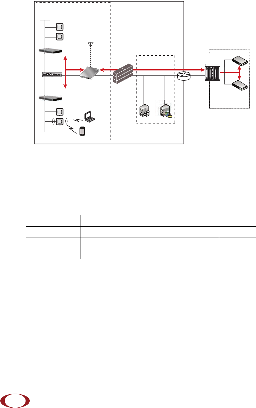
Figure 1 on page 6 shows the logical architecture of the SCRN-320 in the network:
SpiderCloud Wireless, Inc. Proprietary and Confidential
SpiderCloud Radio Node - SCRN-320 Hardware Installation Guide
6
Figure 1 Radio Node Relationship to Enterprise and Mobile Operator Core Networks
Radio Node Models
Table 1 displays the orderable configuration of the SCRN-320 radio node:
Table 1: SCRN-320 Radio Node Configurations
Radio Node Model Description Antenna Type
SCRN-320-02UL LTE Band 2 with license-exempt Band 252 or 255 Internal
SCRN-320-0446 LTE Band 4 with license-exempt Band 252 or 255 Internal
SCRN-320-0446-E LTE Band 4 with license-exempt Band 252 or 255 External
LAN Intranet
DMZ
Enterprise
Mobile
Operator Core
Email Web
Radio Nodes
IPsec
Backhaul
IPsec
Core
Switch
Firewall Security
Gateway
IPsec
SGW
MME
LTE
S1-C
S1-U
LTE
S1
PoE+
Switch
PoE+
Switch
Services Node
GNSS
Antenna
SpiderCloud Wireless, Inc. Proprietary and Confidential
SpiderCloud Radio Node - SCRN-320 Hardware Installation Guide
7
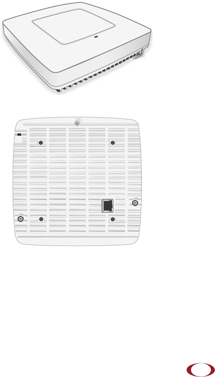
Radio Node System Isometric Top View and Bottom View
The following drawings display an isometric top and bottom views of the radio node:
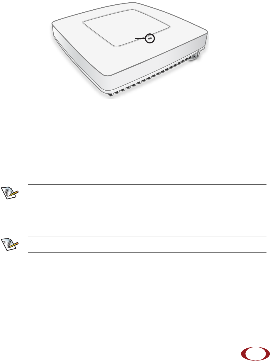
Figure 2 Radio Node Top View
Figure 3 Radio Node Bottom View
SpiderCloud Wireless, Inc. Proprietary and Confidential
SpiderCloud Radio Node - SCRN-320 Hardware Installation Guide
8
Antennas
The radio node includes four internal Tx/Rx antennas with a peak gain of 5dBi and operates in 2x2 mode
with MIMO. and one internal network listen antenna. Figure 4 shows the location of the licenced and
unlicensed LTE antennas:
Figure 4 External Antenna Band Locations
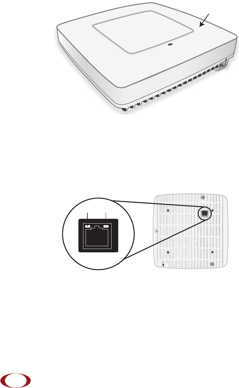
Ports
The radio node has one 1 Gigabit Ethernet port that supports a Category 5e (Cat 5e) or better twisted-pair
cable with an RJ-45 connector. Figure 5 shows the Ethernet port. There are two LEDs on the connector:
•Link: Steady green state indicates a normal Layer 2 link connection has been established.
•Activity: Yellow blinking indicates data activity.
Figure 5 Ethernet Port
Unlicensed
LTE
Unlicensed
LTE
Licensed
LTE
Licensed
LTE
Internal
Sniffer
Antenna
Ethernet
Port
Link Activity
SpiderCloud Wireless, Inc. Proprietary and Confidential
SpiderCloud Radio Node - SCRN-320 Hardware Installation Guide
9
The Top-Panel LED
The radio node has one top-panel tricolor (RGB) LED to indicate power and status. This is the only LED
visible under normal operating conditions. When the radio node initially boots the LED cycles through a
number of colors and flashing behaviors until it is fully operational. Status indications: boot, normal,
disabled, fault, emergency call, radio node tracking.
Figure 6 Radio Node Tricolor LED
Input Power
The radio node receives its power from a standard Power Over Ethernet (PoE+) switch (typical) or injector.
The radio node is fully compliant with the IEEE 802.3at PoE+ specification.
Per IEEE 802.3at, use standard Cat 5e or better twisted-pair cable with a maximum length restriction of
100 meters (328 feet) for PoE+. This restriction minimizes power loss between the PoE+ power source
and the radio node.
When connecting the radio node to a PoE+ switch, ensure that the switch port is statically configured to
deliver minimum 25W of power.
Power is distributed over two pairs of the four available pairs in Cat 5e or better cables. The
radio node can accept power on either used or un-used pairs.
Some PoE switches may be factory configured to deliver lower power per port. If this is the
case change the configuration during installation.
LED
Note
Note
SpiderCloud Wireless, Inc. Proprietary and Confidential
SpiderCloud Radio Node - SCRN-320 Hardware Installation Guide
10
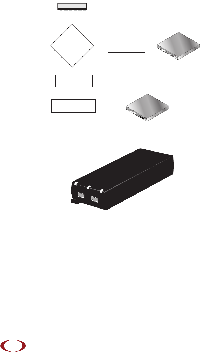
Figure 7 shows the valid radio node cabling/powering options:
Figure 7 Valid Radio Node Cabling/Powering Options
The illustration below shows a generic single-port PoE+ injector. Use this injector only when a PoE+
Ethernet switch is not available.
Figure 8 Typical PoE+ Injector
To connect the PoE+ injector to a radio node
Step 1 Attach the injector power cord to a power source.
Step 2 Connect an unpowered Ethernet cable from a switch to the IN port on the injector.
Step 3 Connect an Ethernet cable from the injector’s OUT port to the radio node. The injector will
now inject power onto a pair of wire pairs in the cable. The radio node will expect a nominal
48V DC input (57V max) from a typical PoE+ injector.
Services Node
PoE+ Switch
Out
In Services Node
PoE+ Switch or
PoE+ Injector
PoE+ Injector
Non PoE+ Switch
OUT IN
CONNECT PoEPLUS ON
SpiderCloud Wireless, Inc. Proprietary and Confidential

SpiderCloud Radio Node - SCRN-320 Hardware Installation Guide
11
System Specifications
The SCRN-310 radio node has the following chassis measurements, power requirements, and
environmental requirements, and complies with the following standards. Refer to the feature guide for your
services node software release for release-specific features and specifications.
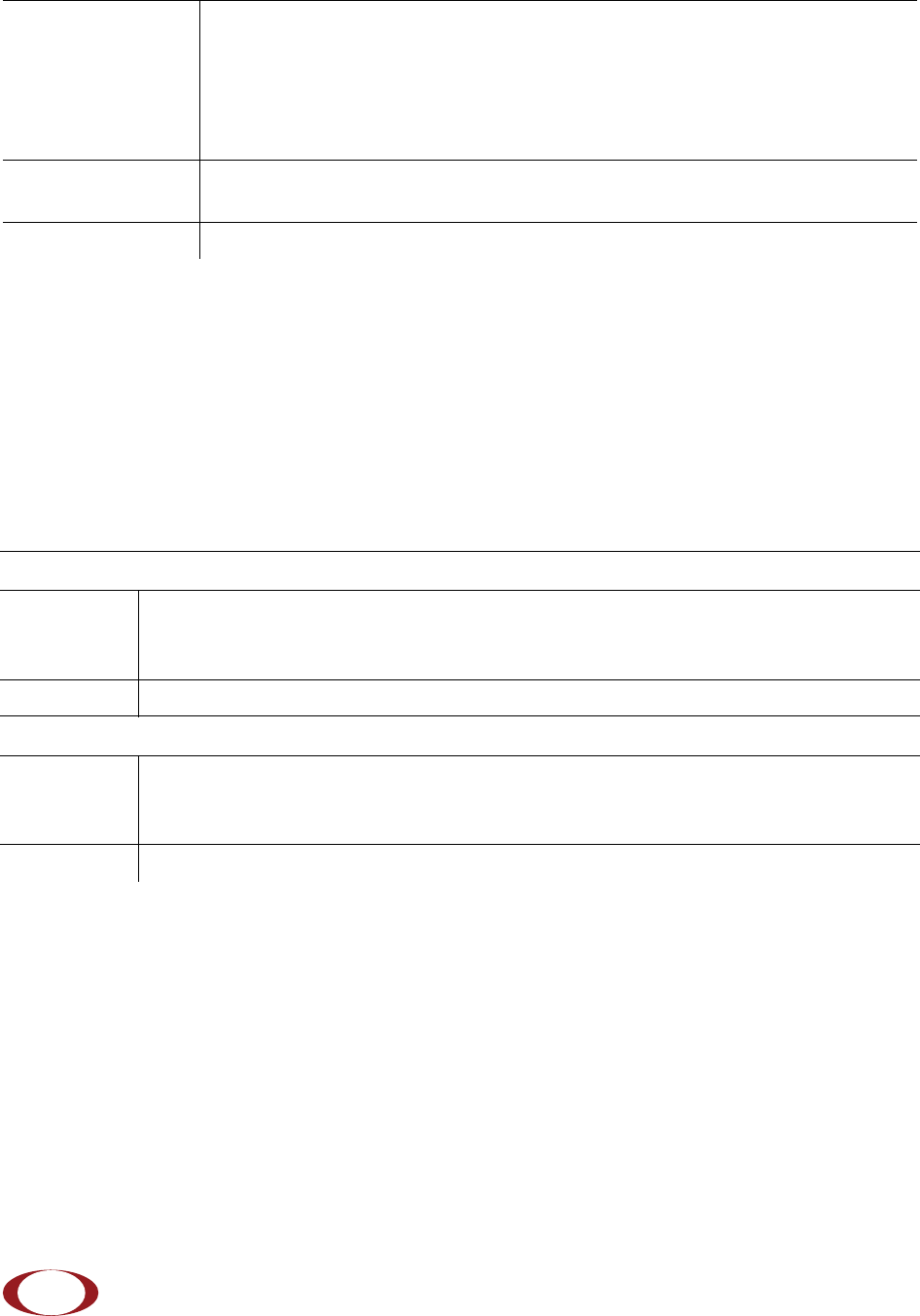
Table 2: Radio Node Specifications
Dimensions Height:1.83 cm (7.2 in.)
Width: 1.83 cm (7.2 in.)
Depth: 36 cm (1.4 in.)
Weight 1.23 kg. (2.7 lbs)
Active Sessions per
Radio Node Up to 64 active LTE users
Peak Data Rate Downlink 300 Mbps; Uplink 50 Mbps (at 20 MHz)
Voice Services VoLTE; 4 data bearers per UE
Power Requirements Licensed: Maximum transmit power: 2x250 mW (27 dBm)
Unlicensed: Maximum transmit power: 2x400 mW (29 dBm)
Input Power Power over Ethernet (PoE+) draws approximately 18W
Channel Size Licensed: 5, 10, 15, 20 MHz
Unlicensed: 20 MHz
Ciphering SNOW 3G and AES air interface encryption
Security Secure boot and secure key storage using Trusted Platform Module (TPM)
functions
IPsec tunneling to services node
X.509 certificate-based authentication
Environmental
Requirements Operating temperature range: 0o to 40oC (32o to 104oF)
Non-operating temperature range: 0 to 85oC (32 to 185oF)
Relative humidity: Operating and storage: 0% RH to 90% RH non-condensing
Ingress protection rating: IP30
Physical Interfaces 1 x Gigabit Ethernet 1000 Base-T with an RJ-45 connector
LEDs 1 top-panel tricolor (RGB) LED to indicate power and status
Mounting Wall, Ceiling, Plenum
SpiderCloud Wireless, Inc. Proprietary and Confidential
SpiderCloud Radio Node - SCRN-320 Hardware Installation Guide
12
SCRN-320 Bracket Specifications
The SCRN-320 radio node connects to one of two brackets for ceiling or wall mounting:
• a quarter-inch (0.64 centimeter) deep for cabling through a surface such as a wall or ceiling
• a 1.25 inch (3.18 centimeters) deep for exposed cabling along a hard surface such as brick or
cinder block
Table 3 shows the specification for these brackets:
Antenna Four internal Tx/RX antennas that operate in 2x2 mode with MIMO
One internal network listen antenna
or
Four antenna ports with SubMiniature version A (SMA) coaxial connectors for
external antennas
One internal network listen antenna
Synchronization IEEE 1588v2-based PTP based frequency synchronization to services node
Cellular network listen for phase synchronization to LTE macro eNodeBs
MTBF 1,363,791 hours at +40°C (104°F)
Table 3: Radio Node Specifications
0.25-Inch Bracket
Dimensions Height:1.57 cm (6.2 in.)
Width: 1.3 cm (5.1 in.)
Depth: 0.64 cm (0.25 in.)
Weight 0.17 kg. (5.8 oz)
1.25-Inch Bracket
Dimensions Height:1.57 cm (6.2 in.)
Width: 1.3 cm (5.1 in.)
Depth: 3.18 cm (1.25 in.)
Weight 0.24 kg. (8.2 oz)
Table 2: Radio Node Specifications (continued)
SpiderCloud Wireless, Inc. Proprietary and Confidential

SpiderCloud Radio Node - SCRN-320 Hardware Installation Guide
13
Compliance
The SCRN-320 complies with the following standards:
Radio Specifications
The SCRN-320 has the following variants:
Select the Radio Node Location
Radio nodes can be installed in a wide range of locations including walls, ceilings, and spaces above the
ceiling. Follow the installation guidelines for selecting appropriate mounting locations for the unit. When
mounting a radio node vertically, align the bottom-side fins vertically for superior cooling.
Refer to the E-RAN Deployment Planning Guide for information about mounting positioning and the affects
on cellular coverage. Always consult local codes about mounting and wiring SpiderCloud Wireless
equipment.
Table 4: SCRN-320 Compliance
Safety EN 60950-160950
CB certification (IEC 60950, UL 60950-1)
EMC/Radio(FCC) FCC Part 15B (Class A)
FCC Part 15E
FCC Part 24
FCC Part 27
R&TTE Directive 1999/5/EC:
• EN 301 489-1, 301 489-23
• EN 301 908-1, 301 908-3, 301 908-14
• EN 50385 and EN 62311 (SAR)
RoHS Directive 2011/65/EU
Table 5: Radio Node Specifications
RadioNodeModel Operating Mode Network Listen Bands Maximum Transmit Power
(per Band)
SCRN-320-0446 Band 4SCRN-320-0446 LTE 700/1900/2100 MHz 2 x 27 dBm LTE licensed
band
SCRN-320-0446-E LTE, Band 252 or 255
unlicensed LTE 700/1900/2100 MHz 2 x 29 dBm 5GHz unlicensed
band
SpiderCloud Wireless, Inc. Proprietary and Confidential
SpiderCloud Radio Node - SCRN-320 Hardware Installation Guide
14
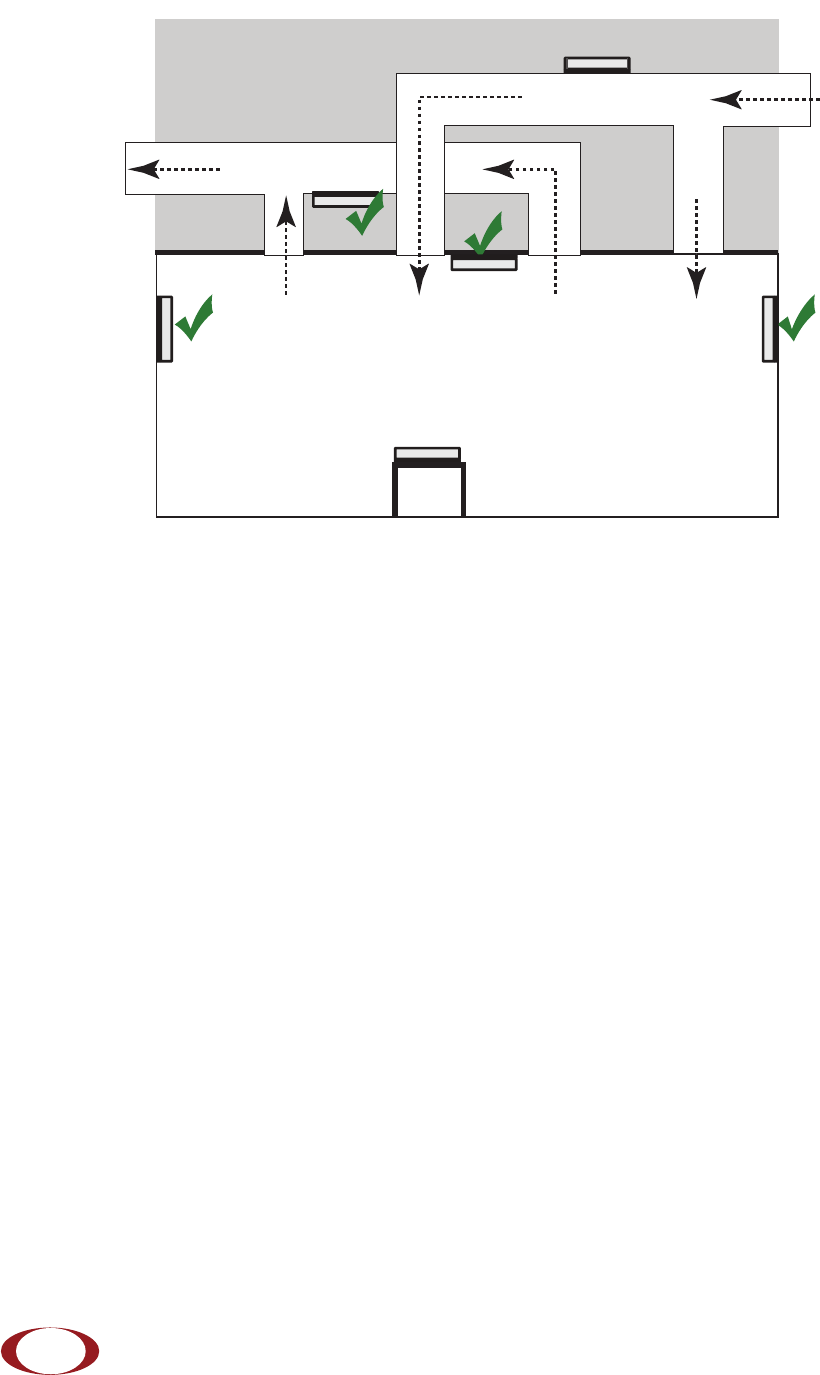
Figure 9 Radio Node Locations
When possible, locate radio node units at least 6 meters (20 feet) from an external wall. This distance
maximizes indoor coverage and minimizes RF leakage outside the building. Refer to the E-RAN
Deployment Planning Guide for Dual-Mode Systems and E-RAN Deployment Planning Guide for LTE
Systems for more information about radio node placement.
When mounting near a wall or other obstruction, orient the mounting bracket such that the transmit
antenna faces towards the coverage area and faces away from the wall. Refer to Bracket Mounting and
Cabling Guidelines on page 14 for more information.
Installation and Mount Bracket Assembly
The radio node slides into one of two brackets for ceiling or wall mounting:
• a quarter-inch (0.64 centimeter) deep for cabling through a surface such as a wall or ceiling
• a 1.25 inch (3.18 centimeters) deep for exposed cabling along a hard surface such as brick or
cinder block
Bracket Mounting and Cabling Guidelines
Incorrectly cabling and mounting a radio node can result in crushed cables and loss of communications to
the unit. Follow these guidelines in cabling the radio node and mounting it on the bracket:
• Ensure that the cabling is properly routed and dressed.
• Ensure that the radio node is fully inserted into the mount bracket so that it locks into place and
is flush. A correctly installed cable should at no time during installation impede inserting the
radio node into the mount bracket.
• Secure the radio node to the mount bracket with a padlock or tie wrap to provide physical
security.
Dead / Non-Circulating
Airspace
Living / Working Space of a Typical
Commercial Building
Drop Ceiling
Wall
Forced-Air Supply
Forced-Air Return
X
X
SpiderCloud Wireless, Inc. Proprietary and Confidential

SpiderCloud Radio Node - SCRN-320 Hardware Installation Guide
15
• When mounting the radio node vertically, orient the bracket such that the bracket keyholes
have the narrow side up as shown in Figure 10.
Typical Radio Node Mounting Options
Radio nodes can be mounted on a wide number of surfaces including the following typical surfaces:
•Light grill: Use bolts, nuts, and washers to secure the universal mount bracket using holes in
the light grill. Adjust the universal mounting bracket until the bracket and light grill holes align.
•Directly on the wall or ceiling: Use drywall screws to secure the universal mount bracket
directly to sheetrock or plasterboard on the wall or ceiling.
•Mud or plaster ring: Secure the universal mount bracket directly on the wall or ceiling as
above with a 3 1/4 inch (8.25 centimeter) mud or plaster ring between the mount bracket and
the mounting service and run the Ethernet cable through ring’s hole.
•Existing infrastructure: Secure the universal mount bracket to existing infrastructure as long
as the radio node RF propagation or existing installed equipment is not adversely impacted.
•Non-metal tiles: Use bracing for rear support and mount the radio node in the center of the tile
for even weight distribution. Ensure that the bracing is the same width as the tile.
•Drop ceiling: Contact your SpiderCloud Wireless representative for recommendations of
supported third-party brackets and clamps.
Installing the Radio Node
The radio node receives its power source over powered Ethernet. If your wiring closet does not have
existing PoE+ equipment, SpiderCloud Wireless recommends a PoE+ power injector for the radio node.
See section Input Power on page 9.
The Ethernet cable can directly through a surface such as a wall or ceiling or route the cable openly:
• Refer to Installing the Radio Node (Method 1) on page 16 for direct cable routing installation
through an opening behind the mount bracket using the shorter mount bracket.
• Refer to Installing the Radio Node (Method 2) on page 17 for open cable routing installation
using the taller mount bracket.
SpiderCloud Wireless, Inc. Proprietary and Confidential
SpiderCloud Radio Node - SCRN-320 Hardware Installation Guide
16
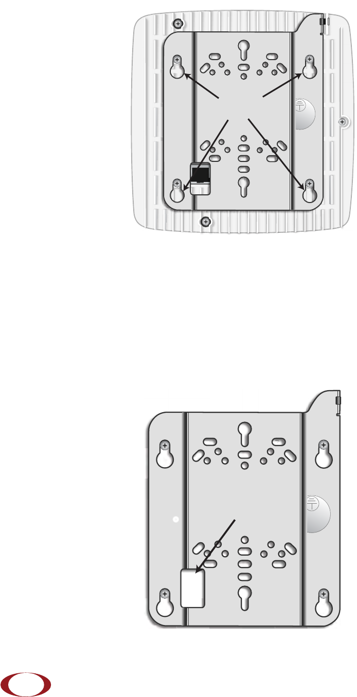
Attach the mount bracket to the radio node as shown in Figure 10:
Figure 10 Radio Node Slides into Mount Bracket
Installing the Radio Node (Method 1)
Use this method with the quarter-inch bracket when routing the Ethernet cable through an opening where
the bracket will be mounted.
To route the cable directly and mount the radio node
Step 1 Cut a hole in the ceiling or wall to route the Ethernet cable through. Align the hole with the
bracket Ethernet cable entry hole.
Step 2 Route the Ethernet cable through the rectangular hole in the mounting bracket.
Figure 11 Mount Bracket with Direct Cable Routing
Bracket
Keyholes
Ethernet Cable
Entry Hole
SpiderCloud Wireless, Inc. Proprietary and Confidential
SpiderCloud Radio Node - SCRN-320 Hardware Installation Guide
17
Step 3 With two user-provided screws, attach the mount bracket assembly to a wall or ceiling. The
screw holes are sized for an M4 (#10) or larger screw. Ensure the screws have a snug fit
onto the studs, sheetrock, anchor, or other material you are bolting onto and that you
match the screw head with the appropriate cutout hole size on the bracket.
If needed, use a flat washer between the bracket and screw head to ensure a secure
fastening.
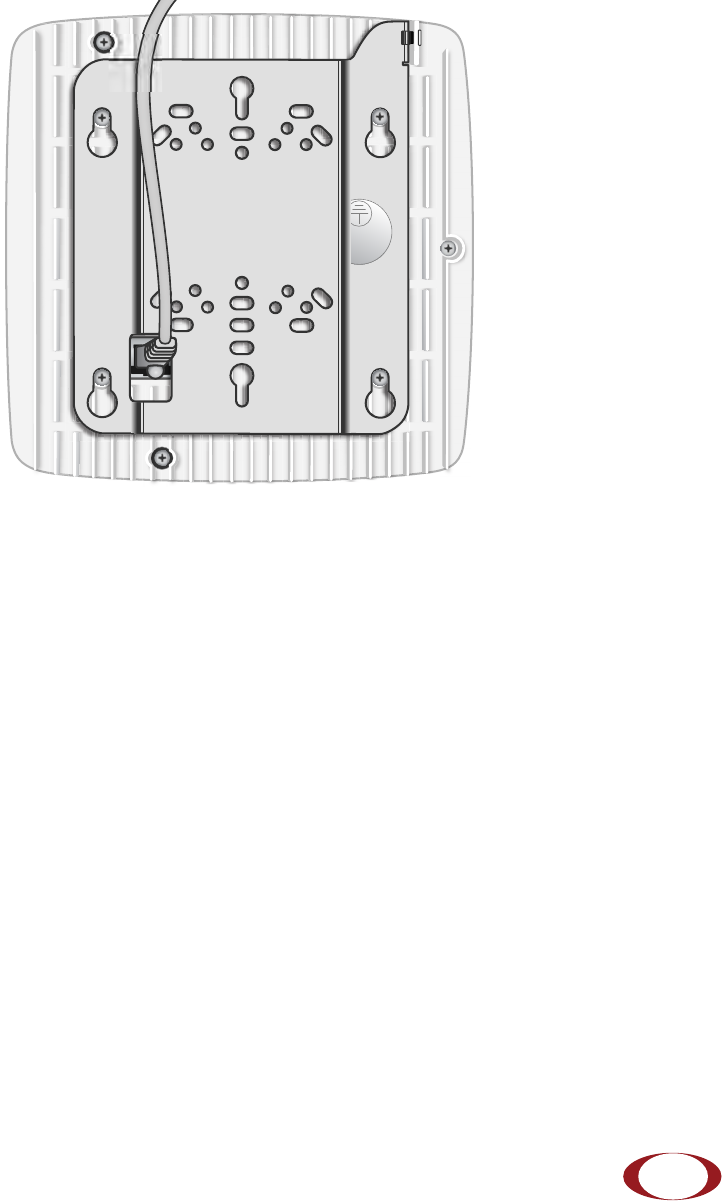
Step 4 Insert the RJ-45 connector into the Ethernet port as shown in Figure 12:
Figure 12 Route and Terminate the Cable
Step 5 Insert the radio node into the mount bracket.
Step 6 Push as much cable back through the wall or ceiling as possible. The mount bracket
assembly has room for some cable slack.
Installing the Radio Node (Method 2)
Use this method with the 1.25 inch bracket when routing an exposed Ethernet cable directly to the radio
node.
To route the cable openly and mount the radio node
Step 1 With two user-provided screws, attach the mount bracket assembly to a wall or ceiling. The
screw holes are sized for an M4 (#10) or larger screw. Ensure the screws have a snug fit
onto the studs, sheetrock, anchor, or other material you are bolting onto and that you
match the screw head with the appropriate cutout hole size on the bracket.
SpiderCloud Wireless, Inc. Proprietary and Confidential
SpiderCloud Radio Node - SCRN-320 Hardware Installation Guide
18
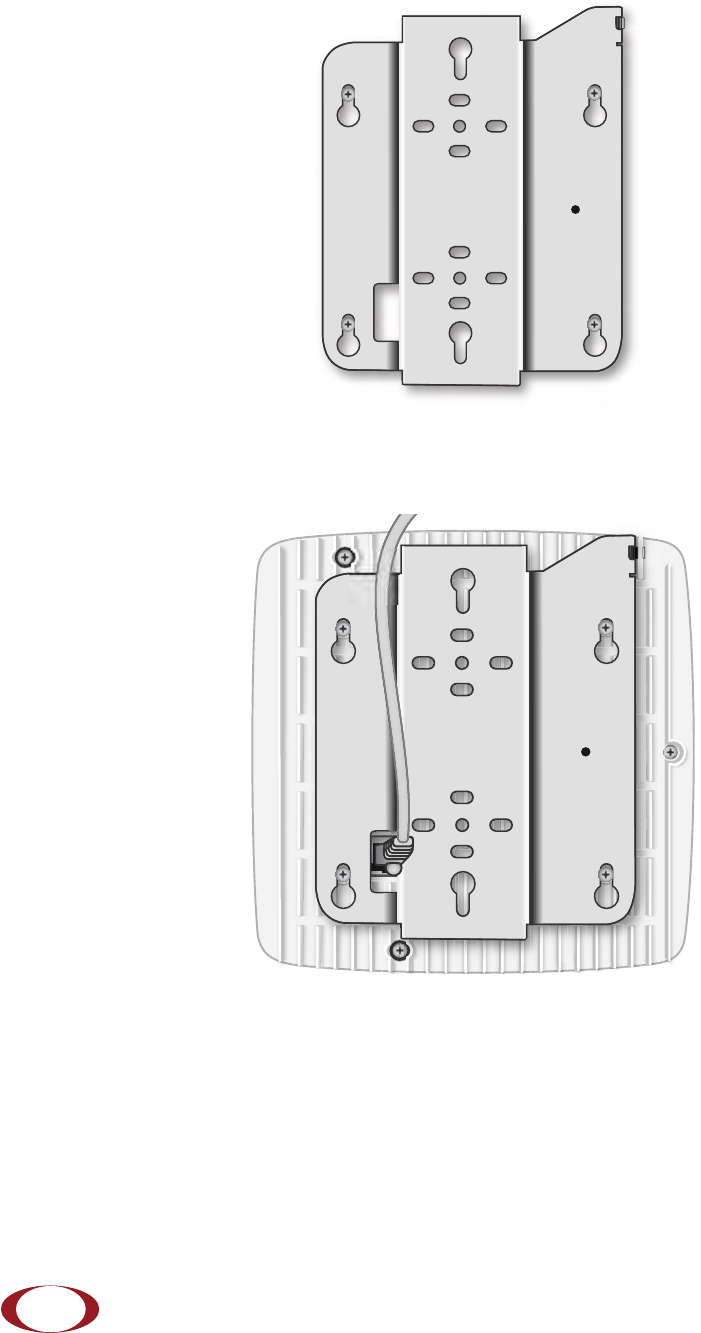
If needed, use a flat washer between the bracket and screw head to ensure a secure
fastening. Figure 13 shows the 1.25-inch mount bracket.
Figure 13 1.25-Inch Mount Bracket
Step 2 Insert the RJ-45 connector through the rectangular bracket opening into the Ethernet port
as shown in Figure 14:
Figure 14 Route and Terminate the Cable
Step 3 Insert the radio node into the mount bracket.
SpiderCloud Wireless, Inc. Proprietary and Confidential
SpiderCloud Radio Node - SCRN-320 Hardware Installation Guide
19
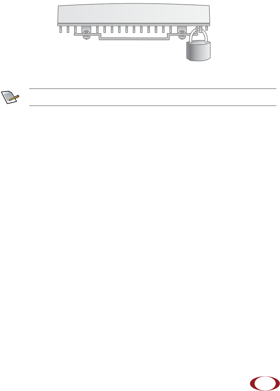
Completing the Installation
Step 1 Attach a padlock or cable tie wrap into the provided slot to secure the unit to the mount
bracket.
Figure 15 Padlock and Lock Holes
Step 2 The radio node boots up and attempts to connect to the services node. Refer to Boot
Sequence and Services Node Communication on page 20 for more information.
Detaching the Radio Node from the Mount Bracket
To remove the radio node from the bracket assembly
Step 1 If needed, remove the padlock or cable tie wrap securing the radio node.
Step 2 Slide the radio node out of the mount bracket.
Step 3 Detach the RJ-45 clip from the Ethernet port and remove the cable from cable brackets
and cable opening.
The lock in the above figure is shown schematically. The orientation is for illustration
purposes (not accurate) since the bracket is typically wall or ceiling mounted.
Note
SpiderCloud Wireless, Inc. Proprietary and Confidential
SpiderCloud Radio Node - SCRN-320 Hardware Installation Guide
20
Boot Sequence and Services Node Communication
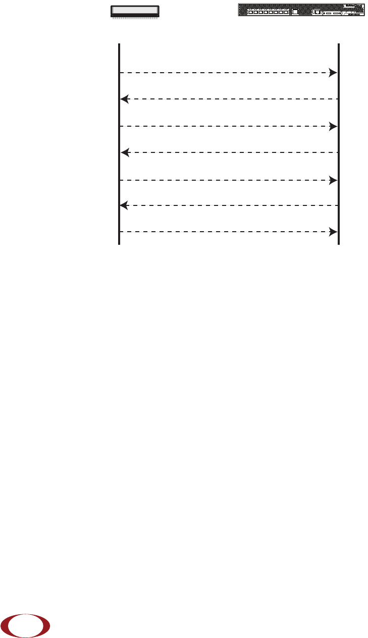
On initial boot, the radio node performs the following boot sequence. When finished, all devices are
reachable. Figure 16 shows the radio node boot sequence:
Figure 16 Radio Node Boot Sequence
Boot Sequence:
1. When the radio node is powered on, the device sends a DHCP Request to the services node
DHCP server to get IP information. The DHCP server is configured on the services node to
respond only to DHCP requests from SpiderCloud Wireless radio nodes. Refer to the SpiderCloud
OS (SCOS) Administrator Guide for more information about the services node DHCP server
configuration.
2. The server responds with the IP addresses of the radio node and the services node (the master of
the radio node).
3. Using its own IP address, the radio node sends a Join Request message to the services node.
The radio node seeks to join the cellular network.
4. The services node responds with a Join Response message indicating whether the radio node is
allowed to join the network or not.
5. The arrival sequence begins. The services node sends the SpiderCloud software image to the
radio node.
6. The radio node boots up the received SpiderCloud software package.
7. The radio node establishes an IPsec tunnel with the services node. Based upon the radio
configuration, the radio node loads the appropriate protocol elements and joins the network.
USB CONSOLE
LK AT LK AT LK AT LK AT LK AT LK AT LK AT LK AT
81234567
LNK ACT
MGMT
POWER STATUS 1 2
SIM 0 SIM 1
Radio Node Services Node
DHCP Request for IP Address
DHCP Response (RN, IP, Controller IP)
Join Request
Join Response (Join Grant, Redirect, Denied)
Arrival sequence begins
Send SpiderCloud software package
Boot-up, bring up the IPsec tunnel and join the network
SpiderCloud Wireless, Inc. Proprietary and Confidential

SpiderCloud Radio Node - SCRN-320 Hardware Installation Guide
21
Radio Node LED Boot Sequence
The radio node state machine is sequential and progresses in the following order:
State 0 -> State 1 -> State 2 -> State 3 -> State 4 -> State 5
A normal boot sequence transitions through all these states sequentially and the LED state transitions
accordingly. If the radio node fails to transition to the next state, the system restarts the boot sequence,
starting with State 0. You can determine the progress during the booting stages by observing the LED color
transitions. On failure, the last LED state will display the state that encountered the failure. Table 6 shows
the radio node boot sequence and corresponding LED behavior:
Table 6: Radio Node LED Boot Sequence
State LED Color Description Possible Failures and Actions
0. Power On/
Reset Flashing
Green This is the initial state on startup.
The radio node bootup is controlled by
firmware in this state.
It will go through a lamp test in this
state. A lamp test involves cycling
through all LED colors.
This state should be very short
lived and should transition to the
next state immediately.
A radio node should not stay in
this state indefinitely.
Note: Flashing Green is also
used to indicate a radio node
that has been administratively
disabled. This can be
determined from the CLI.
1. DHCP Solid
Red The radio node starts by sending out a
DHCP Request.
The radio node moves to the next state
(State 2) upon receiving a DHCP
response and an IP Address.
No DHCP Response, IP
Address not allocated.
Check cabling, DHCP Server
configuration.
2. Join Solid
Blue The radio node has an IP Address and
sends a UDP Join request to the
Serving services node.
The radio node moves to the next state
(State 3) upon getting a JOIN GRANT
from the services node.
No IP reachability to the
services node.
Check IP network between
radio node and services node
for routing issues.
3. TFTP Flashing
Blue The radio node proceeds next to
download the operating system image
from the services node.
The radio node moves to the next state
(State 4) after the image has been
downloaded.
Failure to download TFTP
image.
Check firewall between radio
node and services node.
SpiderCloud Wireless, Inc. Proprietary and Confidential

SpiderCloud Radio Node - SCRN-320 Hardware Installation Guide
22
Radio Node LED Management
The LED display is active by default, but can be deactivated in light-sensitive environments as needed.
Even when the display is disabled, the LED will be lighted during the following conditions:
• while the radio node is booting
• if the radio node or cell is in fault state
• if there is an active emergency call
• if the locate radio node feature is active
• if the follow IMSI feature is active
Table 7 shows the default LED behavior of the radio node:
* Refer to the SpiderCloud OS (SCOS) Administrator Guide for information about the locate radio node
and follow IMSI features.
4. Operating
System Booting Flashing
Green The radio node loads the operating
system and starts the default platform
applications.
The radio node moves to the next state
(State 5) when it establishes
connectivity with the service node.
Failure to start the operating
system.
This normally points to a
software/build issue. Please
contact SpiderCloud support.
5. Running Solid
Green The operating system is running. The
radio node continues the startup
sequence, but is now controlled by the
services node.
The operating system is up and
running on the radio node.
Any subsequent state
transitions can now be tracked
from events and logs on the
services node.
Table 7: Radio Node LED Behavior
LED Status Flash Rate
Green: slow flashing The radio node or radio is
administratively disabled Approximately ½ second on, 1½ sec. off
Green: fast flashing Booting Approximately 1.4 second on/off cycle
Green: solid Operational
Red: solid Fault
Red: fast flashing One or more emergency UMTS calls
active Approximately 1 second on/off cycle
Blue: fast flashing Locate radio node enabled* Approximately 1 second on/off cycle
Blue: solid Follow IMSI enabled and that IMSI is
camped on aa cell in the radio node*
Off Powered off or LED disabled
Table 6: Radio Node LED Boot Sequence (continued)
State LED Color Description Possible Failures and Actions
SpiderCloud Wireless, Inc. Proprietary and Confidential

SpiderCloud Radio Node - SCRN-320 Hardware Installation Guide
23
To disable the LED display
Step 1 From the Configuration Mode, issue the set System RadioNode LED DefaultMode
Dark command to disable the LED display:
set System RadioNode LED DefaultMode Dark
Step 2 Issue the show System RadioNode LED command to verify the configuration:
show System RadioNode LED
DefaultMode Dark;
To re-enable the LED display
Step 1 From the Configuration Mode, issue the set System RadioNode LED DefaultMode
Standard command to re-enable the LED display:
set System RadioNode LED DefaultMode Standard
Step 2 Issue the show System RadioNode LED command to verify the configuration:
show System RadioNode LED
DefaultMode Standard;
The SpiderCloud Documentation Set
The SpiderCloud documentation set includes:
•The SpiderCloud System Description provides an overview of how the SpiderCloud system fits
within an operator’s network and in an enterprise, describes key features of the system, and
provides specifications for the services and radio nodes.
•The SpiderCloud Feature Description provides high-level descriptions of the E-RAN system
features, their impact on the product components (services nodes and radio nodes),
manageability considerations, and feature benefits.
•The SpiderCloud OS (SCOS) Administrator Guide provides procedures for configuring the
software environment and internetworking between the services node and radio node devices.
•The SpiderCloud Services Node Hardware Installation Guide provides hardware specifications
and installation instructions.
•The SpiderCloud Radio Node Hardware Installation Guide provides hardware specifications and
installation instructions.
•The E-RAN Deployment Planning Guide provides information about planning and dimensioning
E-RAN systems.
•The SpiderCloud OS (SCOS) CLI User Guide provides an introduction to the key features and
functionalities of the SpiderCloud Command Line Interface (CLI).
•The SCOS NB Data Model Reference Guide provides details about the objects and parameters
that comprise the system configuration and operational state.
•The SpiderCloud OS Faults, Conditions, and Events Reference Guide provides details about
all alarms, conditions, and events in the system.
•The SpiderCloud System Commissioning Guide provides information about turning up a
SpiderCloud E-RAN with the Local Configuration Interface (LCI) graphical user interface.
•The Performance Measurements for Dual-Mode Small-Cell E-RANs provides a reference guide
to UMTS and LTE Key Performance Indicators (KPI) that monitor the health and state of the E-
RAN system.
SpiderCloud Wireless, Inc. Proprietary and Confidential

SpiderCloud Radio Node - SCRN-320 Hardware Installation Guide
24
•The Performance Measurements for LTE Small-Cell E-RANs provides a reference guide to Key
Performance Indicators (KPI) that monitor the health and state of an LTE E-RAN system.
•The SpiderNet Management System Installation and Administration Guide provides information
about installing the SpiderNet network management server and client and using it to remotely
manage E-RAN deployments.
•The E-RAN Troubleshooting Guide provides information about diagnosing and correcting
problems with installing, provisioning, administering, and maintaining SpiderCloud equipment
and services.
•The Troubleshooting E-RAN Systems with SpiderNet provides information about diagnosing
and correcting problems in the SpiderCloud system with the SpiderNet network management
system.
•The SpiderCloud Time Zone Reference Guide provides the information required to configure the
time zone for SpiderCloud services nodes.
•The SpiderCloud Call Performance Event Reporting Guide provides detailed information about
call performance events files including the file format, reported events, and event parameters.
•The SpiderNet NBI Integration Guide provides information about integrating the SpiderNet
network management system into operator’s Northbound Interface (NBI) Operations Support
Systems (OSSs) to surveil SpiderCloud networks.
SpiderCloud Wireless, Inc. Proprietary and Confidential
25
SpiderCloud Radio Node - SCRN-320 Hardware Installation Guide
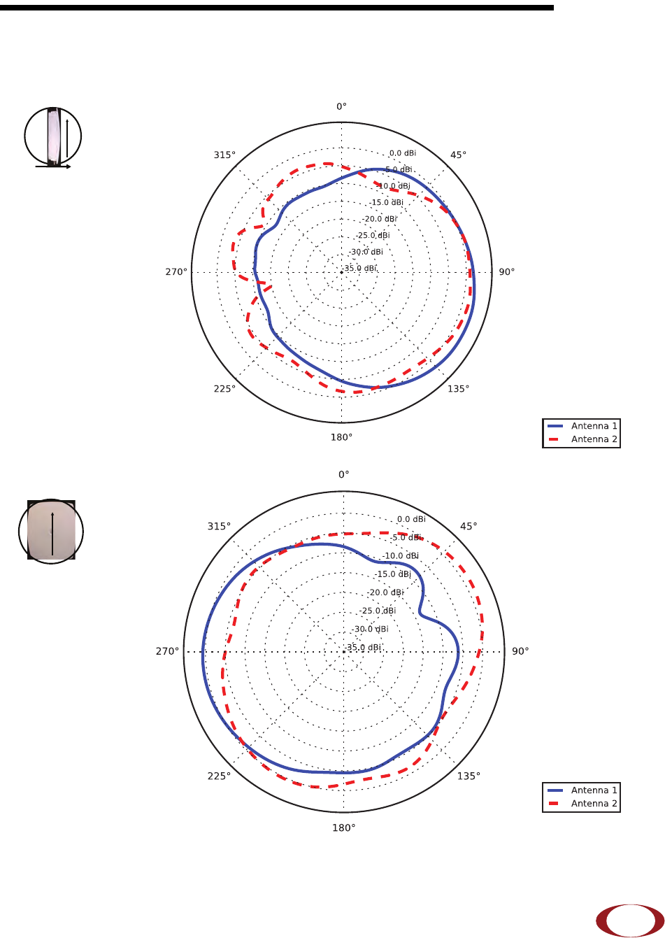
Appendix A: LTE Antenna Patterns
LTE Band 2
Frequency: 1960 MHz. Peak Gain: 3.21 Dbi.
Frequency: 1960 MHz. Peak Gain: 1.50 Dbi.
0º
Front
90º
Up
90º
0º
Up
SpiderCloud Wireless, Inc. Proprietary and Confidential
SpiderCloud Radio Node - SCRN-320 Hardware Installation Guide
26
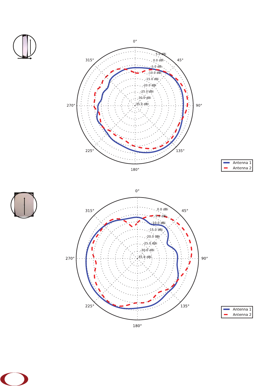
LTE Band 4
Frequency: 2145 MHz. Peak Gain: 4.10 Dbi.
Frequency: 2145 MHz. Peak Gain: 2.63 Dbi.
0º
Front
90º
Up
90º
0º
Up
SpiderCloud Wireless, Inc. Proprietary and Confidential