Spinal Modulation orporated MN20700-03 Wireless transmitter User Manual user maual
Spinal Modulation, Incorporated Wireless transmitter user maual
UserManual.wiki
>
Spinal Modulation orporated
>
MN20700 03 User Manual
user maual
Navigation menu
Upload a User Manual
Namespaces
Wiki Guide
HTML
PDF
Info
Views
User Manual
Discussion / Help
Navigation
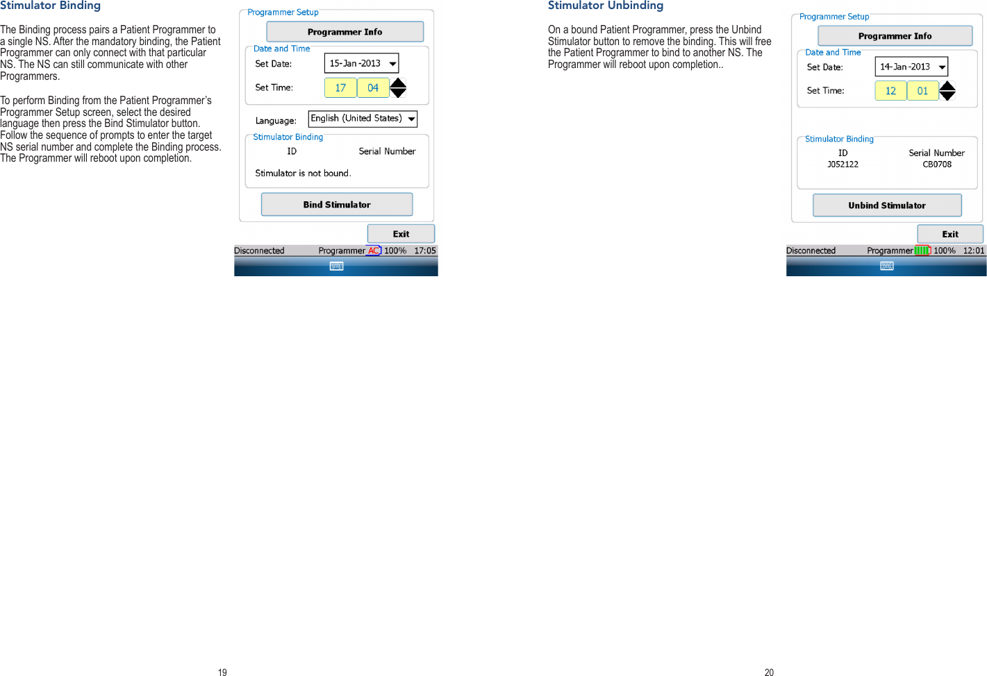
![Table of ContentsEXPLANATION OF SYMBOLS ON PRODUCT OR PACKAGE LABELING ........................................... 1INTRODUCTION ..................................................................................................................................... 2Indications for Use .............................................................................................................................. 2Description .......................................................................................................................................... 2Warnings ............................................................................................................................................. 2Precautions ......................................................................................................................................... 3CLINICAL PROGRAMMER SYSTEM OVERVIEW ................................................................................. 4Clinical Programmer Features ............................................................................................................ 4Magnet ................................................................................................................................................ 5Charging the Clinical Programmer Battery ......................................................................................... 5Programmer Power Up ....................................................................................................................... 5MAIN MENU ............................................................................................................................................ 6Demo .................................................................................................................................................. 6Programmer Setup ............................................................................................................................. 6Change the Date and Time ....................................................................................................................................7Switch to FCE Programmer ...................................................................................................................................7Set Password ......................................................................................................................................................... 7Establishing Communication with the NS Device ............................................................................... 7Back to Main Menu ............................................................................................................................. 8NAVIGATION AND SCREEN ELEMENTS .............................................................................................. 8Neurostimulator Dashboard ................................................................................................................ 8Programmer Status Bar ...................................................................................................................... 9Workspace Navigation ........................................................................................................................ 9Temporary and Permanent Programming ........................................................................................ 10More on Editing Text Fields .............................................................................................................. 10USING THE WORKSPACES................................................................................................................. 10Prole Workspace............................................................................................................................. 10Patient Information Tab [Prole>Patient] .............................................................................................................. 11Clinic Information Tab [Prole>Clinic] ...................................................................................................................12Stimulator Information Tab [Prole>NS] ............................................................................................................... 12Leads Information Tab [Prole>Leads] .................................................................................................................13System Information Tab [Prole>System] ............................................................................................................13Stim Workspace................................................................................................................................ 14Stim Tabs [Stim>Target Name] ............................................................................................................................. 14Impedance Tabs [Stim>Impedance] ..................................................................................................................... 17Map Workspace ................................................................................................................................ 17Group Workspace ............................................................................................................................. 17Lead Tabs [Group>Group Name] ......................................................................................................................... 17Periodic Stimulation .............................................................................................................................................17TNS Rework Procedure [Utility>Rework] .............................................................................................................18Hibernate [Utility>Hibernate] ................................................................................................................................18Stimulator Binding ............................................................................................................................ 19Stimulator Unbinding ........................................................................................................................ 20GUIDANCE AND MANUFACTURER’S DECLARATIONS .................................................................... 21APPENDIX I: PROGRAMMABLE PARAMETERS AND VALUES ......................................................... 25APPENDIX II: TROUBLESHOOTING ................................................................................................... 26](https://usermanual.wiki/Spinal-Modulation-orporated/MN20700-03/User-Guide-2028597-Page-2.png)
![11 12Patient Information Tab [Profile>Patient]Enter or modify the patient information in the elds provided:• Patient Name: Enter the patient’s name using the on-screen keyboard.• ID: Enter the patient’s unique identication using the on-screen keyboard.• Date of Birth: Enter the patient’s date of birth using the drop-down calendar.• Primary and Secondary Diagnosis: Select the patient’s diagnosis from a drop-down list (Refer to Appendix I for selection set) • Notes: Enter notes if needed.NOTE: Pressing the “áü” button near the space bar allows the use of accented characters.Clinic Information Tab [Profile>Clinic]Enter or modify the physician and clinic information in the text elds provided:• Physician Name• Clinic Name• Clinic After Hours Contact Phone Number• Clinic Phone Number• Clinic Email• Clinic AddressStimulator Information Tab [Profile>NS]The NS tab provides a summary of information related to the NS.• Date of Implant: Enter the Stimulator date of use using the drop-down calendar.• Implant Battery Voltage: The current battery voltage is automatically displayed here.• History: Shows recent programming history.NOTE: The battery information pertains to an INS and does not pertain to the TNS.](https://usermanual.wiki/Spinal-Modulation-orporated/MN20700-03/User-Guide-2028597-Page-8.png)
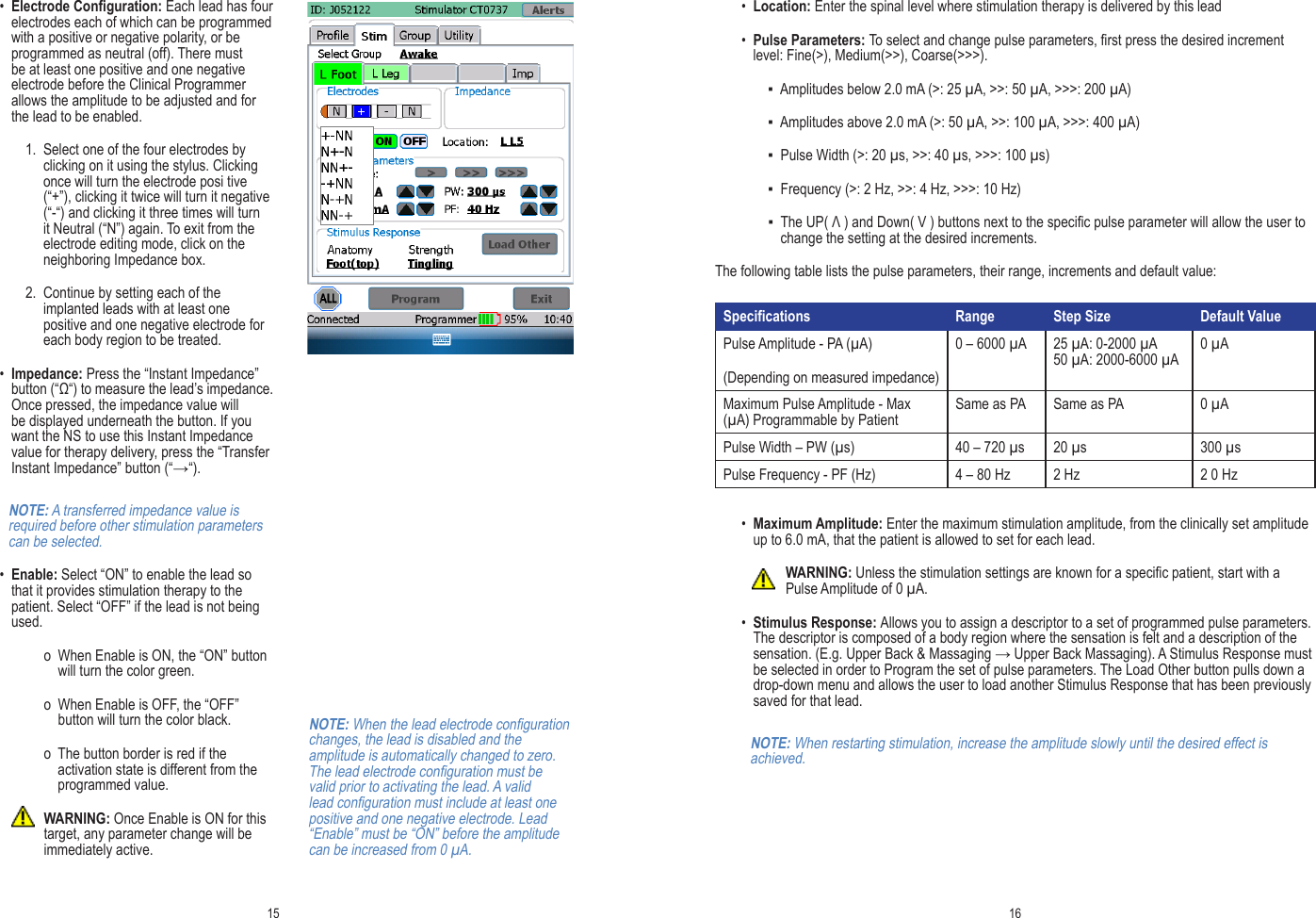
![13 14Leads Information Tab [Profile>Leads]Lead 1 through Lead 4 are the default labels used to identify the implanted leads in the “Stim” Workspace. It is recommended that these names be changed into something more meaningful, for example the body region it covers.• Target Name: for each of the implanted leads, enter the body region covered (text eld).For each of the leads enter the Lot and Model number:• Lot #: Enter the Lot number found on the lead packaging.• Model #: Enter the lead Model number.System Information Tab [Profile>System]From the system tab the following system parameters can be managed: • Periodic Impedance Interval: Set the periodicity with which you want the system to measure lead impedance.• Follow-up Period: A calculated eld which displays the recommended follow-up time based on the programmed settings. It is an indicator of when the programmer will run out of memory and will begin to overwrite old data for impedance measurements.• Ramp Duration: Ramp duration is how long it takes for the NS to reach the requested amplitude. If set to 8 seconds, the NS will take 8 seconds to get from 0 to the requested amplitude when a lead is switched from not enabled to enabled. Ramping also occurs when the step between the current amplitude and the next amplitude is greater than 100 mV.• Magnet Magnet Stim On/Off Time: Allows you to control how long it takes before a magnet held over the device switches off or back on delivered therapy.Stim WorkspacePress the “Stim” tab to access the Stimulation Settings Workspace. The Stimulation Settings Workspace is divided into ve tabs which are used to:• Activate (turn on) up to four leads• Adjust electrode congurations• Measure impedance• Set nominal values to begin stimulation• Perform trial mapping• Conrm the response and sensation of specic body regions to be stimulatedStim Tabs [Stim>Target Name]The Stim tabs are the main tabs from which therapy is controlled and programmed. This can be done either temporarily (testing) or permanently. • Select Group: Select the group for which you want to change the stimulation settings.NOTE: in the Group Workspace, up to four different groups can be dened each with their own stimulation parameters. A group can be linked for example to a specic activity or posture. Refer to the Group Workspace section in this manual for more information.• Select the Tab: Labeled with the target for which you want to adapt stimulation parameters. (In the sample screen e.g. “L Foot”)NOTE: There are up to four tabs that can be labeled with the body region in which stimulation with the corresponding lead is targeting (dened in Prole>Leads). For each body region (lead) stimulation can be adjusted independently.• Patient Refresh Impedance: This allows the impedance to be remeasured and used for therapy on the Patient Programmer whenever the patient turns a Lead Enable from OFF to ON. NOTE: the programmed Pulse Amplitude will be adjusted based on the updated impedance to maintain a constant therapy voltage.](https://usermanual.wiki/Spinal-Modulation-orporated/MN20700-03/User-Guide-2028597-Page-9.png)
![17 18Impedance Tabs [Stim>Impedance]The Impedance Button (Ω) initiates impedance measurements between adjacent electrode couples in all of the congured leads and displays on the Imp screen.Group WorkspacePress the “Group” tab to access Group Workspace. The Group Workspace is divided into four tabs (Groups) by default named “Awake”, “Sleeping”, Exercising” and “Sitting”). Each tab summarizes Group specic settings for each of the implanted leads. These Groups can be easily programmed as needed by the patient using the Patient Programmer.Lead Tabs [Group>Group Name]Each Group can be congured by selecting the desired tab.• Name: The Group can be renamed here (free-form text entry)• For Patient Use: The Group will be displayed on the Patient Programmer only if this box is checked. Note that the currently active Group must be checked/enabled.• Lead 1 through Lead 4: The Stimulus Response for each Lead within a Group can be changed here. Stimulus Responses that have been previously saved for that Lead will be shown in the drop-down menu.Periodic StimulationPeriodic Stimulation can be toggled On or Off (green button indicates On). When On, the clinician can program Stimulation On and Off durations independently. Once programmed, therapy will turn on and off according to the programmed durations when:• out of session, or• in session in the Group Workspace (this allows the clinician to evaluate and optimize On/Off durations)When in session in the Stim Workspace, Periodic Stimulation will be inactive (stimulation will remain ON)to allow the clinician to optimize pulse parameters.Rework Tabs [Utility>Rework]This screen provides one-button automation of the normal TNS rework procedure:The following steps are performed:1. Impedance Check: Electrode impedances are measured on all leads and compared against expected load xture values.NOTE: the user should connect the standard load xture prior to this test. If the xture is not available, this step can be ignored and the remaining two steps will still occur.2. Set Nominal values: all patient values are cleared in the NS and therapy settings are set to nominal.3. Perform NS self-check: a self-test is started on the NS. Upon next connection, the Programmer Alert screen will show any detected NS problems.Additional: The ‘Exit Hibernate’ and ‘Battery Attach’ dates are provided to assist the user in determining when the TNS battery should be replaced.Hibernate Tabs [Utility>Hibernate]‘Hibernate’ is used to keep the NS in a low-power state after manufacturing, while in storage, prior to initial clinical use. When connecting a Clinical Programmer to a device in Hibernation, the user will have the option to exit Hibernation. ‘Hibernate’ is normally not needed after initial clinical use.](https://usermanual.wiki/Spinal-Modulation-orporated/MN20700-03/User-Guide-2028597-Page-11.png)