Spinal Modulation orporated MN20700-03 Wireless transmitter User Manual user maual
Spinal Modulation, Incorporated Wireless transmitter user maual
user maual
Copyright © 2012 Spinal Modulation, Inc. All rights reserved. Unauthorized duplication or use is prohibited.
AXIUM, SPINAL MODULATION and the Man in Circle Design are trademarks and/or registered trademarks
of Spinal Modulation, Inc.
Clinical Programmer
Model MN20700-03
User Manual
Authorization to afx the CE mark
granted in 2011
Table of Contents
EXPLANATION OF SYMBOLS ON PRODUCT OR PACKAGE LABELING ........................................... 1
INTRODUCTION ..................................................................................................................................... 2
Indications for Use .............................................................................................................................. 2
Description .......................................................................................................................................... 2
Warnings ............................................................................................................................................. 2
Precautions ......................................................................................................................................... 3
CLINICAL PROGRAMMER SYSTEM OVERVIEW ................................................................................. 4
Clinical Programmer Features ............................................................................................................ 4
Magnet ................................................................................................................................................ 5
Charging the Clinical Programmer Battery ......................................................................................... 5
Programmer Power Up ....................................................................................................................... 5
MAIN MENU ............................................................................................................................................ 6
Demo .................................................................................................................................................. 6
Programmer Setup ............................................................................................................................. 6
Change the Date and Time ....................................................................................................................................7
Switch to FCE Programmer ...................................................................................................................................7
Set Password ......................................................................................................................................................... 7
Establishing Communication with the NS Device ............................................................................... 7
Back to Main Menu ............................................................................................................................. 8
NAVIGATION AND SCREEN ELEMENTS .............................................................................................. 8
Neurostimulator Dashboard ................................................................................................................ 8
Programmer Status Bar ...................................................................................................................... 9
Workspace Navigation ........................................................................................................................ 9
Temporary and Permanent Programming ........................................................................................ 10
More on Editing Text Fields .............................................................................................................. 10
USING THE WORKSPACES................................................................................................................. 10
Prole Workspace............................................................................................................................. 10
Patient Information Tab [Prole>Patient] .............................................................................................................. 11
Clinic Information Tab [Prole>Clinic] ...................................................................................................................12
Stimulator Information Tab [Prole>NS] ............................................................................................................... 12
Leads Information Tab [Prole>Leads] .................................................................................................................13
System Information Tab [Prole>System] ............................................................................................................13
Stim Workspace................................................................................................................................ 14
Stim Tabs [Stim>Target Name] ............................................................................................................................. 14
Impedance Tabs [Stim>Impedance] ..................................................................................................................... 17
Map Workspace ................................................................................................................................ 17
Group Workspace ............................................................................................................................. 17
Lead Tabs [Group>Group Name] ......................................................................................................................... 17
Periodic Stimulation .............................................................................................................................................17
TNS Rework Procedure [Utility>Rework] .............................................................................................................18
Hibernate [Utility>Hibernate] ................................................................................................................................18
Stimulator Binding ............................................................................................................................ 19
Stimulator Unbinding ........................................................................................................................ 20
GUIDANCE AND MANUFACTURER’S DECLARATIONS .................................................................... 21
APPENDIX I: PROGRAMMABLE PARAMETERS AND VALUES ......................................................... 25
APPENDIX II: TROUBLESHOOTING ................................................................................................... 26
1 2
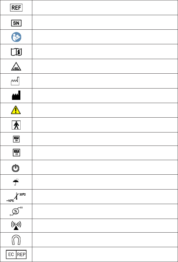
Explanation of Symbols on Product or Package Labeling
Model Number
Serial Number
Read the Manual
Consult the Manual
Contents of Package are Non-Sterile
Manufacturing Date
Manufacturer
Warning. Pay attention.
Protected against Electric Shock
Not waterproof. Applies to the Programmer when it is not in its carrying case.
Limited waterproof. Applies to the TNS.
Applies to the Programmer in its carrying case.
Turns the Programmer ON and OFF.
Turns stimulation OFF on the TNS.
Keep Dry
Store between -10°C and 50°C (14°F and 122°F)
Store between 0 and 93% humidity
The device is a radio transmitter
Magnet. Shows the location of the Programmer magnet.
Authorized European Representative
Introduction
The Clinical Programmer is part of the Spinal Modulation Axium Neurostimulator System. It is intended
to be used by the clinical investigator or a Spinal Modulation representative to query and program the
Neurostimulator (NS), to retrieve data from the NS and to allow for adjustment of the patient’s therapy.
This User Manual gives detailed instructions on how to use the Clinical Programmer safely, how to
recharge it and how to use it to set up the patient’s pain management therapy.
Indications for Use
The Spinal Modulation Neurostimulator System is indicated for the management of chronic intractable
pain.
Description
Patients who are indicated for the Axium Implantable Neurostimulator System (INS) system will rst
undergo a trial period using an external Trial Neurostimulator System (TNS) connected to leads placed
within the epidural space near the dorsal root ganglion (DRG). Up to four leads may be placed and
connected to the Neurostimulator.
Although the leads and stimulator hardware used differ, the programmer hardware and instructions for
programming the TNS and INS devices are the same.
NOTE: In this manual the general abbreviation “NS” is used for information which applies to both
TNS and INS. In all other cases the specic abbreviations “TNS” or “INS” are used.
For specic description of the TNS and INS system components and implant procedures, refer to the
relevant labeling.
Two programmers are available to interact with the NS device.
1. The Clinical Programmer described in this user manual is used to program the stimulation
parameters for the NS, as determined by the physician. The NS delivers the programmed
stimulation parameters (energy) to the implanted Leads.
2. The Patient Programmer allows the patient to adjust the stimulation settings of the NS devices
within limits preset by the physician. The Patient Programmer also allows the patient to turn
stimulation off, if necessary. For further information and instructions related to the patient
programmer, refer to the respective user manual.
Warnings
The Warnings listed below pertain to the Clinical Programmer only:
• The physician must be trained by Spinal Modulation personnel before using the Clinical Programmer.
The Clinical Programmer must be used and maintained in accordance with the information in this
manual.
• Do not use the Clinical Programmer with a NS device that appears to be faulty or fails to properly
communicate.
• Improper use of the Clinical Programmer may cause irreversible injury to the patient. All patients are
to be awake and conversant during the procedure to minimize the likelihood of any nerve damage
• Always set the NS device amplitude to 0 µA when repositioning a lead or attaching the Connector
Cable to the external TNS. When restarting stimulation, increase the NS amplitude slowly until the
desired paresthesia is achieved.
3 4
Precautions
The following precautions should be taken to avoid damage to the Clinical Programmer and to ensure
proper function:
• Do not drop or mishandle the Clinical Programmer. Physical damage to the Clinical Programmer may
impair its function.
• Do not spill uids on or wash the Clinical Programmer. Excessive moisture may impair its function. If
cleaning is necessary, remove soil with a soft damp cloth.
• Do not use abrasive or caustic cleaning products on the Clinical Programmer.
• Do not attempt to open the case for the Clinical Programmer. Attempts to open the case may expose
the Clinical Programmer to elements that alter its function.
• The Clinical Programmer has an internal magnet. Keep the Clinical Programmer away from any
credit cards, hard drives, or magnetic storage devices as it may demagnetize them.
• Do not operate the Clinical Programmer outside the specied temperature range of 5°C to 40°C.
Rapid temperature changes may affect proper device operation.
• Do not store the Clinical Programmer outside the specied temperature range of -10°C to 50°C.
• Do not leave the Clinical Programmer in a car or other places where temperatures can exceed 50°C.
• Do not burn or otherwise dispose of the Clinical Programmer. Fire may cause the internal battery to
explode.
• Do not allow unauthorized use of the Clinical Programmer to avoid injury to patients.
• The NS device can only be programmed using Spinal Modulation’s Clinical or Patient Programmer.
Do not try to use any other manufacturer’s device to program it.
• Do not use the Clinical Programmer or NS in the presence of explosive or ammable gases as this
may cause serious injury.
• Do not use the Programmer Charger if the power cord is damaged, excessively worn or frayed. This
may cause injury or damage the Programmer.
• Frequent programming of the implanted device will cause the battery to deplete faster. Avoid
unnecessary programming.
• If there is any concern regarding the proper function of the Spinal Modulation NS System, please
contact your Spinal Modulation representative.
RF OPERATING FREQUENCIES
Nearby equipment emitting strong magnetic elds can interfere with RF communication, even if the other
equipment complies with CISPR emission requirements. The operating characteristics are as follows:
MICS band: 402-405 MHz
The effective radiated power is below the limits as specied in
Europe: EN ETSI 301 839-2
USA FCC 47 CFR Part 95; 95.601-95.673 Subpart E, 95.1201-95.1219
FCC ID: Y8L-MN20700-03
This device may not interfere with stations operating in the 400.150–406.000 MHz band in the
Meteorological Aids, Meteorological Satellite, and Earth Exploration Satellite Services and must accept
any interference received, including interference that may cause undesired operation.
Clinical Programmer System Overview
The Axium Clinical Programmer allows you to establish two-way communication with the patient’s NS
device for querying and programming.
It is a portable, hand-held device that can be plugged into a power outlet or be powered by an internal
battery. The battery is rechargeable using the power supply provided and a power outlet.
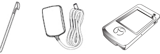
The Clinical Programmer System includes:
• Clinical Programmer with Stylus
• Programmer Charger
• External Auxiliary Magnet
• Programmer Carrying Case
• Clinical Programmer User Manual (this document)
Clinical Programmer Features
With the Clinical Programmer, you can:
• Turn OFF all stimulation.
• Turn stimulation ON for up to four leads and measure lead impedance.
• Change stimulation settings for each lead.
• Congure Patient Controlled Therapy settings for each lead.
• Enter patient and lead identication information, clinician and clinic name and contact information,
and clinician’s notes.
• Create and name groups of stimulation sets with each group containing up to four leads with different
settings on each lead.
• Perform a real time trial (test) to assess the patient stimulation response for each lead.
• Acquire identication, diagnostic, and historic information about the NS device.
Clinical ProgrammerStylus Programmer Charger
5 6
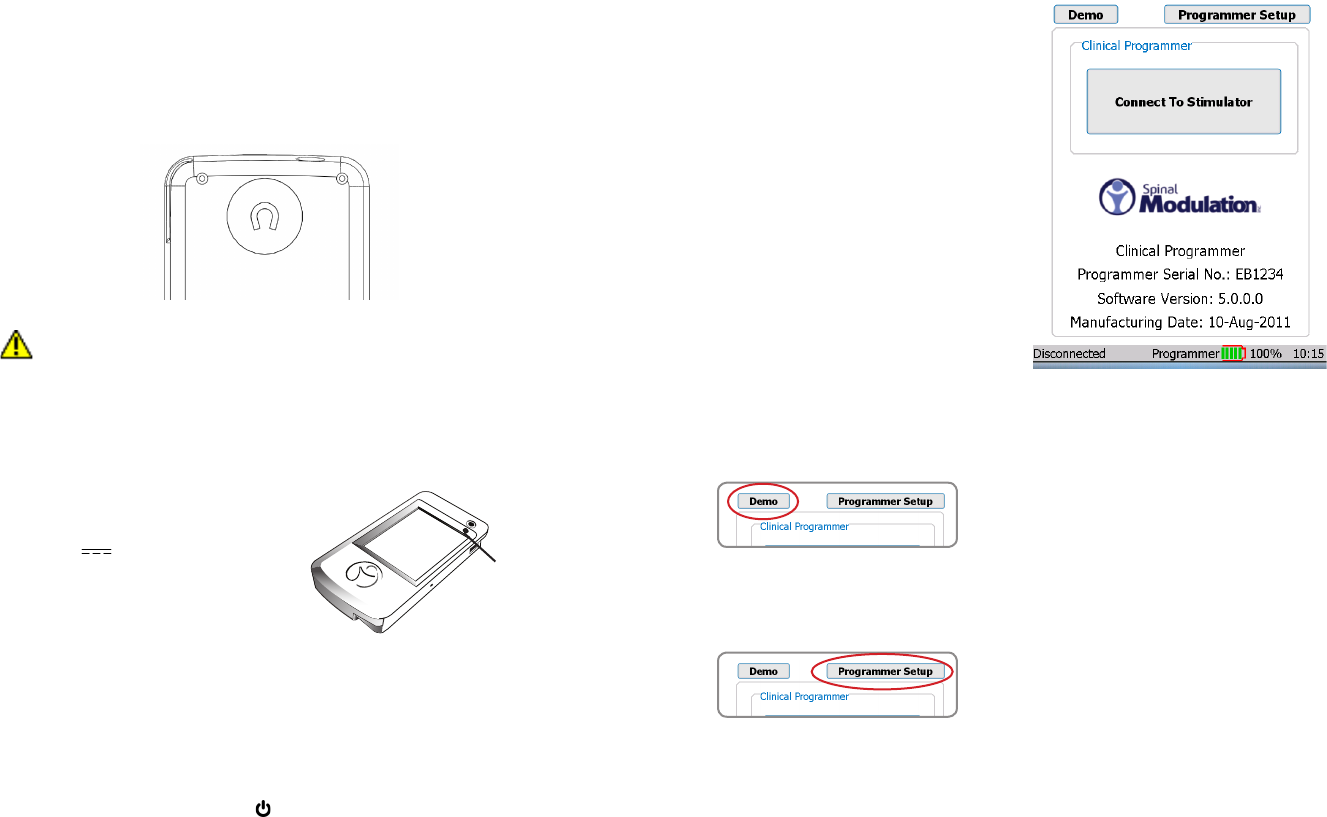
Magnet
A magnet is built into the Clinical Programmer. It is located on the back side of the Programmer
underneath the indent with the magnet symbol (shown below).
The NS system has the capability of detecting the presence of a magnet. The magnet puts the NS device
in communication mode, allowing it to connect to the Programmer.
An alternate function of the magnet is that by holding the magnet over the device long enough, all
stimulation therapy will be switched off or back on. (Refer to the “Workspace - Prole>System” section for
more information).
PRECAUTION: Keep the programmer magnet away from credit cards. It may erase the
magnetic strip and render the card useless.
Charging the Clinical Programmer Battery
You will need the Programmer Charger provided to charge the battery in the Clinical Programmer. It
takes approximately 2–4 hours to fully charge the battery. The battery charge level is indicated in the
“Programmer Status Bar” at the bottom of the screen.
1. Connect the power supply to a power outlet.
Input: 100-240 VAC, 50-60 Hz, 0.6A
Output: 5V 3.0A
2. Connect the Charger to the Programmer.
3. When the battery is charging, the battery icon on
the screen contains “AC”. When the charging is
complete, the indicator next to the battery icon will
be at approximately 100%.
When the Clinical Programmer is connected to a power outlet as described above, it is being powered
by the outlet and will not use battery power. The battery can be expected to last at least 500 discharge
cycles with normal use. Connect the Clinical Programmer to the Charger and attach to an outlet regularly
to keep it charged.
Programmer Power Up
Turn the Clinical Programmer ON by pressing the “ “ button. The Main Menu will be displayed.
NOTE: If the Clinical Programmer screen does not turn on, follow the instructions for charging the
battery, and try again.
Main Menu
The Main Menu displays three primary functions:
• Demo: Puts the system into a stand-
alone demo mode allowing you to use
all programmer functions without it being
connected to a NS.
• Programmer Setup: Allows you to set the
Clinical Programmer date and time, activate
the FCE Workspace on the Programmer,
and set and modify the Programmer
password.
• Connect to Stimulator: Opens a screen
that allows you to communicate with the
NS device.
The Main Menu identies the device as the Spinal
Modulation Clinical Programmer. Furthermore,
Programmer’s Serial Number, Software Version,
and Manufacturing date are displayed.
At the bottom of the Main Menu, the status bar
displays the Programmer – NS connection status,
the battery charge level and the time.
Refer to the
section on the Programmer Status Bar in this User
Manual.
Demo
Select “Demo” on the Main Menu to initiate Demo mode.
Buttons will be purple to indicate that the Programmer
is operating in Demo mode. No NS device is needed for
this mode —just the Programmer. The Programmer will
have simulated NS data on it and will simulate the RF
communication with the NS. This means that at the start of
every Demo session, the data will always be the same.
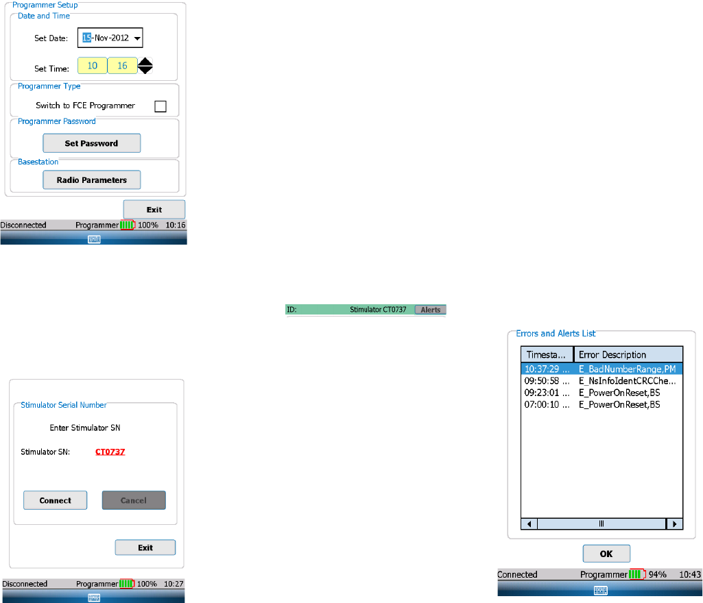
Programmer Setup
Select “Programmer Setup” on the Main Menu to get the
setup screen.
The device is
charging when
the amber light
is on.
7 8
Change the Date and Time
To change the date, select the drop down arrow on the
right side of the “Set Date” box. A calendar will appear
and you can set the month, day and year using your
stylus.
To change the time (24 hour format), rst select the
hour or minute eld that you would like to change.
To change the selected eld, use the “Up” or “Down”
arrows to increase, decrease or toggle the setting.
NOTE: Establishing a connection updates the NS
device’s clock to the newly set time.
Switch to FCE Programmer
By checking this box the Clinical Programmer will get
additional functionality, which should only be used by
Spinal Modulation’s Field Clinical Engineers and Staff.
Set Password
A password may be set to limit access to the
Programmer.
The password is for the Programmer itself and is not
associated with any NS.
Establishing Communication with the NS Device
To change the patient’s stimulation settings, you must
rst establish communication between the Clinical
Programmer and the patient’s NS device.
1. Make sure that the Clinical Programmer is turned on
and the Main Menu screen is displayed
2. Press “Connect to Stimulator” on the Main Menu.
3. Select the text box next to “Stimulator SN:”
4. Enter the serial number using the pop-up keyboard.
If the serial number format is valid for a NS device, the
“Connect” button will be enabled.
5. Press the “Connect” button.
After pressing the “Connect” button, the “Cancel” button
becomes enabled. If the Cancel button is pressed, the
telemetry connection is cancelled.
6. Move the Clinical Programmer magnet over the NS device in a circular motion to connect. The
indicator status bar on the bottom left of the screen will display “Connected” if the connection
attempt is successful. If the Programmer could not communicate with the NS device, an error
message will appear and “Disconnected” will be displayed in the status bar.
NOTE: If after 2 minutes the Clinical Programmer has failed to communicate with the NS device,
the programmer will automatically cancel the connection attempt. Try to communicate with the
NS device by pressing the “Connect” button again moving the magnet symbol on the Clinical
Programmer over the NS device in a circular fashion.
When a successful connection is established, the Programmer chimes and the NS device will be queried.
7. For the duration of the programming session keep the Clinical Programmer within 3 feet of the NS
device. Moving the programmer too far away may cause telemetry connection to be lost.
Back to Main Menu
Located at the bottom right side of the Programmer Connect window, the “Exit” button is used to return to
the Main Menu.
Navigation and Screen elements
Neurostimulator Dashboard
Once the selected NS device is connected to
the Clinical Programmer, the NS Dashboard is
displayed in the screen’s header providing:
• Patient ID: The patient’s ID Number
• Stimulator Serial Number: The NS device’s
serial number
• Alerts Button: The button turns orange when
any of the NS System Alerts become active.
When the “Alerts” button is orange, press the
button to display a window showing details
of all the System Alerts. An example of the
screenshot is shown to the right.
9 10
Programmer Status Bar
Located at the bottom of the Clinical Programmer screen, the Programmer Status Bar displays:
• Programmer-Stimulator Connection Status: Displays the status of the communication between
the Clinical Programmer and the NS device: “Connecting” is displayed when establishing
a connection. “Connected” is displayed when there is communication between the Clinical
Programmer and the NS device. “Disconnected” is displayed when there is no communication
between the Clinical Programmer and the NS device.
• Programmer Battery Level: Displays the Clinical Programmer battery charge level. It is
recommended that the Programmer be plugged in and charging when not in use. Plug in and
charge the Programmer before reaching 30% remaining life.
• Programmer Clock: Displays the time. See User Manual section on Change the Date and Time.
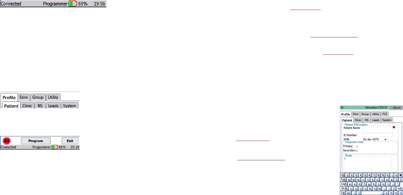
Workspace Navigation
Once the NS is connected, tabs are displayed for
the systems’ four main workspaces (“Prole”, “Stim”,
“Group”, and “Utility”). The Workspaces are used
to view and program the NS therapy settings and
to obtain diagnostic information. A record of the
programmed settings and diagnostic information is generated after every session. A fth Workspace
labeled “FCE” will only appear when FCE mode is ON.
Workspace screens and sub-screens are navigated by selecting the labeled tabs.
Located at the bottom of each of the Workspaces are
the “ALL”, “Program” and “Exit” buttons.
• Exit button: is used to close the current window, end the patient therapy session, and return to
the Main Menu.
• Program button: programs all changes made within the current Workspace.
• ALL button: turns all stimulation off.
NOTE: Returning to the Main Menu or turning off the Programmer will not change any of the
programmed NS settings.
NOTE: When programming is complete, select the “Exit” button to conserve power.
Temporary and Permanent Programming
Whenever a change is made to a parameter value or other data eld while the NS is within telemetry
range, this value immediately becomes temporarily active. The corresponding value or data selection
appears in a red bold underlined font.
NOTE: The “temporarily active” state does not apply to the Group workspace.
Temporary programmed values or text data can be permanently programmed by pressing the program
button. The font color changes from red to black.
NOTE: When leaving a Workspace while values are temporarily active you will be prompted to
either program these values permanently or cancel the pending changes.
NOTE: Parameters can be temporarily active on multiple tabs of the same Workspace.
More on Editing Text Fields
NOTE: Selecting a text eld will pop up a keyboard at the bottom of the screen. To close the
keyboard after modifying the entry, press the keyboard key centered in the blue bar at the bottom
of the screen.
While text elds are being edited, they appear in a black bold
font (no underline). At the same time to the right of the text eld a
red dot indicates that editing is in progress.
Once editing for a eld is complete, tap the red dot to make the
change temporarily active. The red dot disappears and the font
changes from black bold to red bold underlined.
Only upon pressing the programming button does the change
become permanently programmed and the font color changes
from red to black.
Using the Workspaces
Profile Workspace
Press the “Prole” tab to access the Prole Workspace. The Prole Workspace is divided into ve tabs
(“Patient”, “Clinic”, “NS”, “Leads” and “System”) which are used to:
• Enter patient information
• Enter clinician contact information
• Enter NS device information
• Enter lead identication information
• Change basic system parameters
11 12
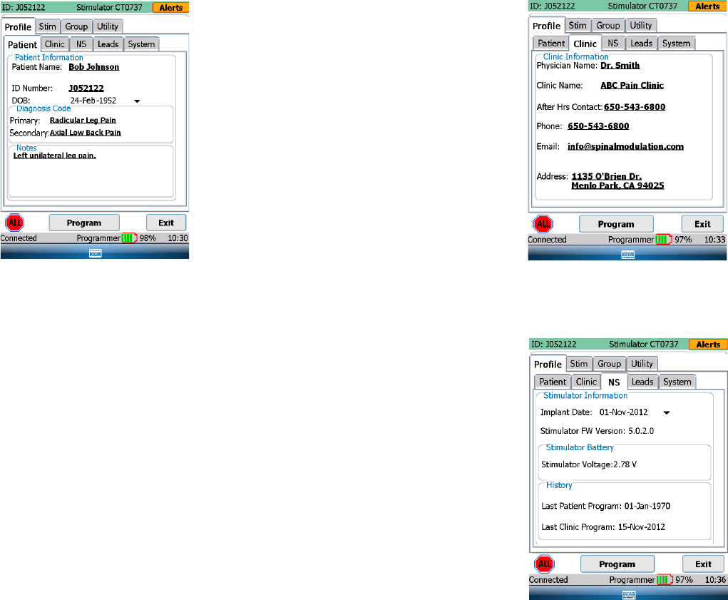
Patient Information Tab [Profile>Patient]
Enter or modify the patient information in the elds
provided:
• Patient Name: Enter the patient’s name using
the on-screen keyboard.
• ID: Enter the patient’s unique identication using
the on-screen keyboard.
• Date of Birth: Enter the patient’s date of birth
using the drop-down calendar.
• Primary and Secondary Diagnosis: Select the
patient’s diagnosis from a drop-down list (Refer
to Appendix I for selection set)
• Notes: Enter notes if needed.
NOTE: Pressing the “áü” button near the space
bar allows the use of accented characters.
Clinic Information Tab [Profile>Clinic]
Enter or modify the physician and clinic information in
the text elds provided:
• Physician Name
• Clinic Name
• Clinic After Hours Contact Phone Number
• Clinic Phone Number
• Clinic Email
• Clinic Address
Stimulator Information Tab [Profile>NS]
The NS tab provides a summary of information related
to the NS.
• Date of Implant: Enter the Stimulator date of
use using the drop-down calendar.
• Implant Battery Voltage: The current battery
voltage is automatically displayed here.
• History: Shows recent programming history.
NOTE: The battery information pertains to an
INS and does not pertain to the TNS.
13 14
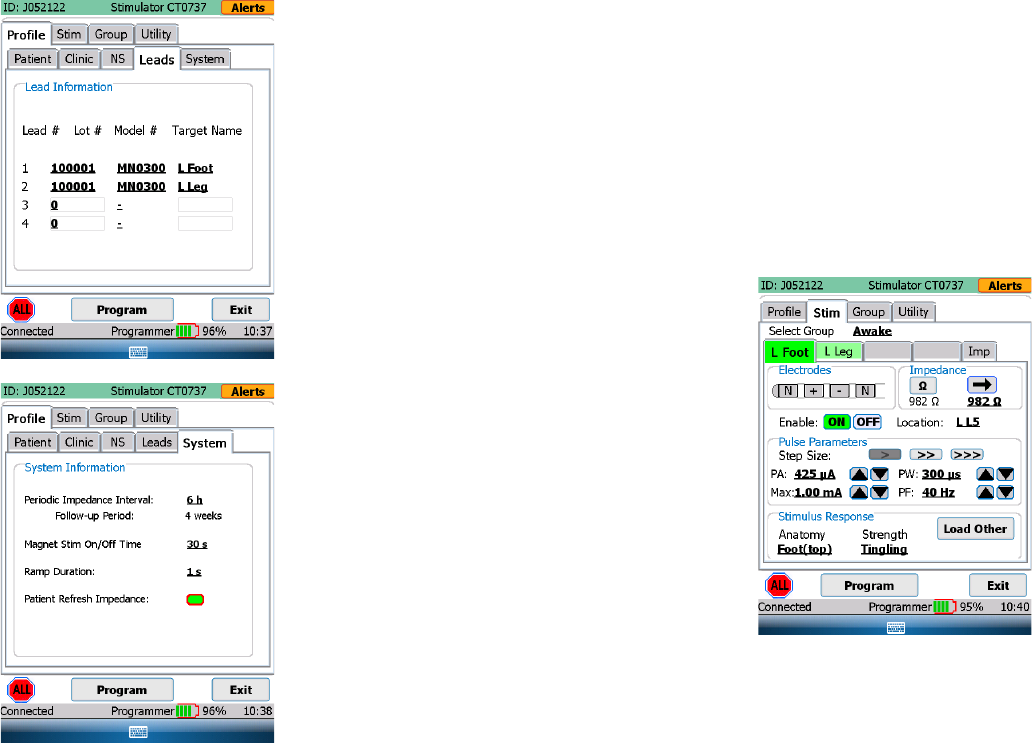
Leads Information Tab [Profile>Leads]
Lead 1 through Lead 4 are the default labels used to
identify the implanted leads in the “Stim” Workspace.
It is recommended that these names be changed into
something more meaningful, for example the body
region it covers.
• Target Name: for each of the implanted leads,
enter the body region covered (text eld).
For each of the leads enter the Lot and Model
number:
• Lot #: Enter the Lot number found on the lead
packaging.
• Model #: Enter the lead Model number.
System Information Tab [Profile>System]
From the system tab the following system parameters
can be managed:
• Periodic Impedance Interval: Set the
periodicity with which you want the system to
measure lead impedance.
• Follow-up Period: A calculated eld which
displays the recommended follow-up time
based on the programmed settings. It is an
indicator of when the programmer will run out
of memory and will begin to overwrite old data
for impedance measurements.
• Ramp Duration: Ramp duration is how long
it takes for the NS to reach the requested
amplitude. If set to 8 seconds, the NS will
take 8 seconds to get from 0 to the requested
amplitude when a lead is switched from not
enabled to enabled. Ramping also occurs when
the step between the current amplitude and the
next amplitude is greater than 100 mV.
• Magnet Magnet Stim On/Off Time: Allows
you to control how long it takes before a
magnet held over the device switches off or
back on delivered therapy.
Stim Workspace
Press the “Stim” tab to access the Stimulation Settings Workspace. The Stimulation Settings Workspace
is divided into ve tabs which are used to:
• Activate (turn on) up to four leads
• Adjust electrode congurations
• Measure impedance
• Set nominal values to begin stimulation
• Perform trial mapping
• Conrm the response and sensation of specic body regions to be stimulated
Stim Tabs [Stim>Target Name]
The Stim tabs are the main tabs from which therapy is
controlled and programmed. This can be done either
temporarily (testing) or permanently.
• Select Group: Select the group for which you
want to change the stimulation settings.
NOTE: in the Group Workspace, up to four
different groups can be dened each with
their own stimulation parameters. A group can
be linked for example to a specic activity or
posture. Refer to the Group Workspace section
in this manual for more information.
• Select the Tab: Labeled with the target
for which you want to adapt stimulation
parameters. (In the sample screen e.g. “L
Foot”)
NOTE: There are up to four tabs that can be
labeled with the body region in which stimulation
with the corresponding lead is targeting (dened
in Prole>Leads). For each body region (lead)
stimulation can be adjusted independently.
• Patient Refresh Impedance: This allows the impedance to be remeasured and used
for therapy on the Patient Programmer whenever the patient turns a Lead Enable from
OFF to ON.
NOTE: the programmed Pulse Amplitude will be adjusted based on the
updated impedance to maintain a constant therapy voltage.
15 16
• Electrode Conguration: Each lead has four
electrodes each of which can be programmed
with a positive or negative polarity, or be
programmed as neutral (off). There must
be at least one positive and one negative
electrode before the Clinical Programmer
allows the amplitude to be adjusted and for
the lead to be enabled.
1. Select one of the four electrodes by
clicking on it using the stylus. Clicking
once will turn the electrode posi tive
(“+”), clicking it twice will turn it negative
(“-“) and clicking it three times will turn
it Neutral (“N”) again. To exit from the
electrode editing mode, click on the
neighboring Impedance box.
2. Continue by setting each of the
implanted leads with at least one
positive and one negative electrode for
each body region to be treated.
• Impedance: Press the “Instant Impedance”
button (“Ω“) to measure the lead’s impedance.
Once pressed, the impedance value will
be displayed underneath the button. If you
want the NS to use this Instant Impedance
value for therapy delivery, press the “Transfer
Instant Impedance” button (“→“).
NOTE: A transferred impedance value is
required before other stimulation parameters
can be selected.
• Enable: Select “ON” to enable the lead so
that it provides stimulation therapy to the
patient. Select “OFF” if the lead is not being
used.
o When Enable is ON, the “ON” button
will turn the color green.
o When Enable is OFF, the “OFF”
button will turn the color black.
o The button border is red if the
activation state is different from the
programmed value.
WARNING: Once Enable is ON for this
target, any parameter change will be
immediately active.
NOTE: When the lead electrode conguration
changes, the lead is disabled and the
amplitude is automatically changed to zero.
The lead electrode conguration must be
valid prior to activating the lead. A valid
lead conguration must include at least one
positive and one negative electrode. Lead
“Enable” must be “ON” before the amplitude
can be increased from 0 µA.
• Location: Enter the spinal level where stimulation therapy is delivered by this lead
• Pulse Parameters: To select and change pulse parameters, rst press the desired increment
level: Fine(>), Medium(>>), Coarse(>>>).
▪ Amplitudes below 2.0 mA (>: 25 µA, >>: 50 µA, >>>: 200 µA)
▪ Amplitudes above 2.0 mA (>: 50 µA, >>: 100 µA, >>>: 400 µA)
▪ Pulse Width (>: 20 µs, >>: 40 µs, >>>: 100 µs)
▪ Frequency (>: 2 Hz, >>: 4 Hz, >>>: 10 Hz)
▪ The UP( Λ ) and Down( V ) buttons next to the specic pulse parameter will allow the user to
change the setting at the desired increments.
The following table lists the pulse parameters, their range, increments and default value:
Specications Range Step Size Default Value
Pulse Amplitude - PA (µA)
(Depending on measured impedance)
0 – 6000 µA 25 µA: 0-2000 µA
50 µA: 2000-6000 µA
0 µA
Maximum Pulse Amplitude - Max
(µA) Programmable by Patient
Same as PA Same as PA 0 µA
Pulse Width – PW (µs) 40 – 720 µs 20 µs 300 µs
Pulse Frequency - PF (Hz) 4 – 80 Hz 2 Hz 2 0 Hz
• Maximum Amplitude: Enter the maximum stimulation amplitude, from the clinically set amplitude
up to 6.0 mA, that the patient is allowed to set for each lead.
WARNING: Unless the stimulation settings are known for a specic patient, start with a
Pulse Amplitude of 0 µA.
• Stimulus Response: Allows you to assign a descriptor to a set of programmed pulse parameters.
The descriptor is composed of a body region where the sensation is felt and a description of the
sensation. (E.g. Upper Back & Massaging → Upper Back Massaging). A Stimulus Response must
be selected in order to Program the set of pulse parameters. The Load Other button pulls down a
drop-down menu and allows the user to load another Stimulus Response that has been previously
saved for that lead.
NOTE: When restarting stimulation, increase the amplitude slowly until the desired effect is
achieved.
17 18
Impedance Tabs
[Stim>Impedance]
The Impedance Button (Ω) initiates impedance
measurements between adjacent electrode couples
in all of the congured leads and displays on the Imp
screen.
Group Workspace
Press the “Group” tab to access Group Workspace.
The Group Workspace is divided into four tabs (Groups)
by default named “Awake”, “Sleeping”, Exercising” and
“Sitting”). Each tab summarizes Group specic settings
for each of the implanted leads. These Groups can be
easily programmed as needed by the patient using the
Patient Programmer.
Lead Tabs [Group>Group Name]
Each Group can be congured by selecting the desired
tab.
• Name: The Group can be renamed here (free-
form text entry)
• For Patient Use: The Group will be displayed
on the Patient Programmer only if this box is
checked. Note that the currently active Group
must be checked/enabled.
• Lead 1 through Lead 4: The Stimulus
Response for each Lead within a Group can be
changed here. Stimulus Responses that have
been previously saved for that Lead will be
shown in the drop-down menu.
Periodic Stimulation
Periodic Stimulation can be toggled On or Off (green button indicates On). When On, the clinician can
program Stimulation On and Off durations independently. Once programmed, therapy will turn on and off
according to the programmed durations when:
• out of session, or
• in session in the Group Workspace (this allows the clinician to evaluate and optimize On/Off durations)
When in session in the Stim Workspace, Periodic Stimulation will be inactive (stimulation will remain ON)
to allow the clinician to optimize pulse parameters.
Rework Tabs
[Utility>Rework]
This screen provides one-button automation of the
normal TNS rework procedure:
The following steps are performed:
1. Impedance Check: Electrode impedances are
measured on all leads and compared against expected
load xture values.
NOTE: the user should connect the standard load
xture prior to this test. If the xture is not available,
this step can be ignored and the remaining two
steps will still occur.
2. Set Nominal values: all patient values are cleared in
the NS and therapy settings are set to nominal.
3. Perform NS self-check: a self-test is started on
the NS. Upon next connection, the Programmer Alert
screen will show any detected NS problems.
Additional: The ‘Exit Hibernate’ and ‘Battery Attach’ dates are provided to assist the user in determining
when the TNS battery should be replaced.
Hibernate Tabs
[Utility>Hibernate]
‘Hibernate’ is used to keep the NS in a low-power state
after manufacturing, while in storage, prior to initial
clinical use. When connecting a Clinical Programmer
to a device in Hibernation, the user will have the option
to exit Hibernation. ‘Hibernate’ is normally not needed
after initial clinical use.
19 20
Stimulator Binding
The Binding process pairs a Patient Programmer to
a single NS. After the mandatory binding, the Patient
Programmer can only connect with that particular
NS. The NS can still communicate with other
Programmers.
To perform Binding from the Patient Programmer’s
Programmer Setup screen, select the desired
language then press the Bind Stimulator button.
Follow the sequence of prompts to enter the target
NS serial number and complete the Binding process.
The Programmer will reboot upon completion.
Stimulator Unbinding
On a bound Patient Programmer, press the Unbind
Stimulator button to remove the binding. This will free
the Patient Programmer to bind to another NS. The
Programmer will reboot upon completion..

21 22
GUIDANCE AND MANUFACTURER’S DECLARATION
Electromagnetic Emissions
The Spinal Modulation Neurostimulator System is intended for use in the electromagnetic environment
specied below. The customer or the user of the Spinal Modulation Neurostimulator System should
assure that it is used in such an environment.
Immunity IEC 60601 Test Level Compliance
Level
Electromagnetic
Environment Guidance
Electrostatic
discharge (ESD) IEC 61000-4-2
± 6 kV contact
± 8 kV air
Floors should be wood,
concrete or ceramic tile.
If oors are covered with
synthetic material, the relative
humidity should be at least
30%.
Electrical fast
transient/burst
IEC 61000-4-4
± 2 kV for power supply lines
± 1 kV for input/output lines Pass
Mains power quality should be
that of a typical commercial or
home environment
Surge
IEC 61000-4-5
± 1 kV line(s) to line(s)
± 2 kV line(s) to earth
Mains power quality should be
that of a typical commercial or
home environment
Voltage dips,
short interruptions
and voltage
variations on
power supply
input lines
IEC 61000-4-11
<5% UT (>95% dip in UT)
for 0.5 cycle
40% UT (60% dip in UT)
for 5 cycles
70% UT (30% dip in UT)
for 25 cycles
<5% UT (>95% dip in UT)
for 5 s
NOTE UT is the a.c. mains
voltage prior to application of
the test level.
Mains power quality should be
that of a typical commercial or
home environment
Power frequency
(50/60 Hz)
magnetic eld
IEC 61000-4-8
3 A/m
Power frequency magnetic
elds should be at levels
characteristic of a typical
location in a typical
commercial, hospital, or home
environment.
Guidance and Manufacturer’s Declarations
GUIDANCE AND MANUFACTURER’S DECLARATION
Electromagnetic Emissions
The Spinal Modulation Neurostimulator System is intended for use in the electromagnetic environment
specied below. The customer or the user of the Spinal Modulation Neurostimulator System should
assure that it is used in such an environment.
Emissions test Compliance Electromagnetic Environment – Guidance
RF Emissions 1 Group 2
The Spinal Modulation Neurostimulator System must emit
electromagnetic energy in order to perform its intended
function. Nearby electronic equipment may be affected.
RF emissions
CISPR 11 Class B
Harmonic emissions
IEC 61000-3-2 Class B
Voltage uctuations/
icker emissions
IEC 61000-3-3
Complies
The Spinal Modulation Neurostimulator System is suitable for
use in all establishments, including domestic establishments
and those directly connected to the public low voltage power
supply network that supplies buildings used for domestic
purposes.
CISPR 14-1 Complies The Clinical Programmer is not intended to be connected to
other equipment except the Programmer Charger.
23 24
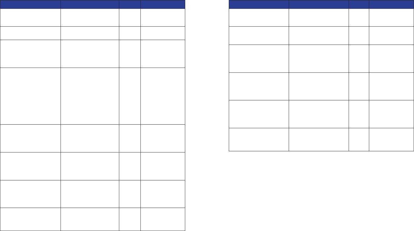
GUIDANCE AND MANUFACTURER’S DECLARATION
Electromagnetic Immunity
The Spinal Modulation Neurostimulation System is intended for use in the electromagnetic
environment specied below. The customer or the user of the Spinal Modulation Neurostimulation
System should assure that it is used in such an environment.
Immunity
Test
IEC 60601 Test
Level
Compliance
Level Electromagnetic Environment Guidance
Conducted RF
IEC 61000-4-6
Radiated RF
IEC 61000-4-3
3 Vrms
150 kHz to 80
MHz
3 V/m
80 MHz to 2.5
GHz
3 V
3 V/m
Portable and mobile RF communications
equipment should be used no closer to any part
of Spinal Modulation Neurostimulation System,
than the recommended separation distance
calculated from the equation applicable to the
frequency of the transmitter.
The recommended separation distance is a
minimum of 0.2 meter for transmitters of 80 MHz
to 2.5 GHz
Interference may occur in the vicinity of
equipment marked with the following symbol:
NOTE 1 At 80 MHz and 800 MHz, the higher frequency range applies.
NOTE 2 These guidelines may not apply in all situations. Electromagnetic propagation is affected by
absorption and reection from structures, objects and people.
Recommended separation distances between portable and mobile RF communications
equipment and the Spinal Modulation Neurostimulation System
The Spinal Modulation Neurostimulation System is intended for use in an electromagnetic environment
in which radiated RF disturbances are controlled. The customer or the user of the Spinal Modulation
Neurostimulation System can help prevent electromagnetic interference by maintaining a minimum
distance between portable and mobile RF communications equipment (transmitters) and the System.
Rated maximum output
power of transmitter
(W)
Separation distance according to frequency of transmitter
(m)
150 kHz to 80 MHz 80 MHz to 800 MHz 800 MHz to 2.5 GHz
0.01 0.12m 0.12m 0.23m
0.1 0.37m 0.37m 0.74m
1 1.17m 1.17m 2.33m
10 3.70m 3.70m 7.37m
100 11.70m 11.70m 23.30m
NOTE 1 At 80 MHz and 800 MHz, the higher frequency range applies.
NOTE 2 These guidelines may not apply in all situations. Electromagnetic propagation is affected by
absorption and reection from structures, objects and people.
25 26
Appendix I: Programmable parameters and values
Parameter Programmable Values Default
Pulse Amplitude 0 – 6000 µA
0-2000 µA (25 µA increments)
2000-6000 µA (50 µA increments)
0 µA
Maximum Pulse Amplitude Same as Pulse Amplitude 0 µA
Pulse Width 40 – 720 µs (20µs increments) 300 µs
Pulse Frequency 4 – 80 Hz (2 Hz increments) 20 Hz
Data Field Selectable Values
Diagnosis
(Primary and Secondary)
Abdominal Pain; Axial Low Back Pain; Axial Neck Pain; CRPS
Type 1; CRPS Type 2; Diabetic Peripheral Neuropathy; FBSS;
FNSS; Lower Extremity Neuropathic Pain; Neuropathic Pain; Other;
Peripheral Neuropathy; Peripheral Vascular Disease; Phantom Pain;
Post-Herpetic Neuralgia; Post Surgical Pain; Radicular Arm Pain;
Radicular Leg Pain; Thoracic Pain; Upper Extremity Neuropathic
Pain; Visceral Pain;
Periodic Impedance Interval Off; 30 s; 1 min; 5 min; 20 min; 30 min; 1 h; 6h; 12 h; 1 days; 3 days;
7 days; 10 days; 30 days
Lead Model Number MN0300; MN0400, MN10350, MN10450, MN20350, MN20450
Stimulus Response Anatomy Off; Neck; Shoulder; Scapula; Upper Back; Middle Back; Lower
Back; Back & Leg; Thigh; Knee; Lower Leg; Ankle; Foot(top);
Foot(bottom); Toes; Chest; Axilla; Ribs; Abdomen; Hip; Groin; Upper
Arm; Elbow; Forearm; Hands; Fingers
Stimulus Response Sensation Off; Burning; Buzzing; Cold; Comforting; Cramping; Heavy;
Massaging; Numb; Other; Pain; Paresthesia; Pressure; Relief;
Soothing; Spasm; Tapping; Tingling; Vibrating; Warm
Spine Location L L1; R L1; L L2; R L2; L L3; R L3; L L4; R L4; L L5; R L5; L T1; R
T1; L T2; R T2; L T3; R T3; L T4; R T4; L T5; R T5; L T6; R T6; L T7;
R T7; L T8; R T8; L T9; R T9; L T10; R T10; L T11; R T11; L T12; R
T12; L S1; R S1; L S2; R S2; L S3; R S3; L S4; R S4; L S5; R S5; L
C1; R C1; L C2; R C2; L C3; R C3; L C4; R C4; L C5; R C5; L C6; R
C6; L C7; R C7; L C8; R C8
Magnet Turnoff Time Off; 1 s; 2 s; 3 s; 4 s; 5 s; 6 s; 7 s; 8 s; 9 s; 10 s; 15 s; 20 s; 25 s;
30 s; 40 s; 50 s; 1 min; 70 s; 80 s; 90 s; 100 s; 110 s; 2 min
Ramp Duration 1 s; 2 s; 3 s; 4 s; 5 s; 6 s; 7 s; 8 s
Appendix II: Troubleshooting
Pop-up Messages Condition Buttons Resolution
All stimulation has been
turned OFF.
All stimulation turned off due to
data corruption.
“OK” Contact your
Spinal Modulation
Representative.
Cancelled Connect
Request
Cancel was pressed with
connecting attempt in progress.
Changes since last
programming were lost
due to loss of connection
with the stimulator. Please
reconnect to stimulator.
Communication was lost prior
to programming attempt.
“OK” Reconnect to stimulator
and re-enter program
changes.
Connected to stimulator.
Communication is poor.
All RF channels have noise
levels above the noise
threshold.
Try moving to an area with
fewer sources of noise.
Connecting to stimulator... “Connect” button on the main
menu was pressed.
Connection Established. Connection attempt was
successful.
“OK”
Connection with
stimulator was lost.
Please reconnect.
Dropped RF connection. “OK”
Do you want to program
changes?
A new Workspace or Exit button
was selected without saving
(programming) changes.
“Yes”
“No”
“Cancel”
Invalid FCE password.
Please try again.
Invalid FCE password was
entered.
“OK” Only Spinal Modulation
representatives should
access the FCE mode.
Lead N detected a
Current Too High
condition.
During an impedance
measurement, the measured
current was too high.
“OK” Repeat measurement. If
problem reoccurs, contact
your Spinal Modulation
representative.
Lead N impedance of
NNN Ω is out of range.
Lead impedance is out of range “OK” Repeat measurement or
accept as is.
Maximum stimulation
output has been reached.
Maximum stimulation output
has been reached (4.6V).
“OK” Investigate lead integrity.
The stimulator is in
hibernation.
Battery Voltage = xxx
Do you want to exit
hibernation?
27 28
Pop-up Messages (Cont.) Condition Buttons Resolution
Please specify a Stimulus
Response before programming
Attempt to program a set of
pulse parameters without a
Stimulus Response Name.
“OK” Select stimulus
response.
Programmer battery is low.
Please recharge.
PDA battery reaches 30%. “OK” Recharge as soon as
possible.
Programmer is booting after
a reset. When you click OK
the Programmer will switch
off. Press the Power button to
restart.
Hardware reset Button
on the PDA was pressed,
Programmer detected an
error or the Programmer is
launched for the rst time.
Press Power button.
Programmer storage space is
low. Please contact your Spinal
Modulation representative for
maintenance.
PDA storage is at full
capacity (log les are stored
on the PDA with each
signicant operation such
as programming). Message
is displayed and le logging
continues by deleting old
log les to make room
for new log les. Normal
operation continues after user
acknowledgement.
“OK” Contact your
Spinal Modulation
Representative.
Stimulation for one or more
leads has been turned OFF.
One or more leads turned off
due to Low Impedance.
“OK” Perform impedance
measurement and re-
enable if within range.
Otherwise, investigate
lead integrity.
Stimulation has been turned
OFF due to a magnet.
Stimulation can be turned
off by applying a magnet for
the duration specied by the
Magnet Stim On/Off Time
programmable parameter.
“OK” Stimulation can be
turned back on by
applying magnet for
the same “Magnet
Stim On/Off Time”.
Stimulation has been turned
OFF.
Stimulation can be turned off,
either by the “All Stim OFF”
software button on the INS
programmer, or the Off switch
on the TNS.
“OK”
Stimulator battery has reached
End of Service (EOS).
Stimulation has been turned
OFF permanently.
Battery has reached EOS
voltage. Stimulation is
disabled in order to preserve
power for RF communication.
“OK” Schedule replacement
of the Stimulator.
Pop-up Messages (Cont.) Condition Buttons Resolution
Stimulator battery has reached
the Elective Replacement
Indicator (ERI).
Battery has reached ERI
voltage.
“OK” Schedule replacement
of the Stimulator.
Stimulator clock is HH:MM. Do
you want to update Stimulator
clock?
The NS internal time is out
of sync with the Programmer
time.
“Yes”
“No”
The stimulator has been set to
default values.
The Programmer has
encountered an NS with
unreadable or invalid data.
Parameters have been set and
programmed to default values.
“OK” Setup device
parameters as
desired.
The stimulator has unreadable
data. Please reconnect with
programmer in FCE mode or
contact your Spinal Modulation
representative
NS has unreadable data (such
as Trim data)
“OK” Contact your
Spinal Modulation
Representative.
The stimulator is in Upgrade
Mode. Please reconnect with
programmer in FCE mode or
contact your Spinal Modulation
representative.
NS in Boot mode. All
stimulation is disabled.
“OK” Contact your
Spinal Modulation
Representative.
Unable to connect to
stimulator. Make sure the
programmer is close to the
stimulator and try again.
Can’t connect to the NS. “OK” Move the programmer
above the Stimulator
in circular motions.
Error messages may contain additional troubleshooting information such as “
Error Code: 04-123,
BadParameterValue
”. This is an aid for Spinal Modulation engineers to debug errors.