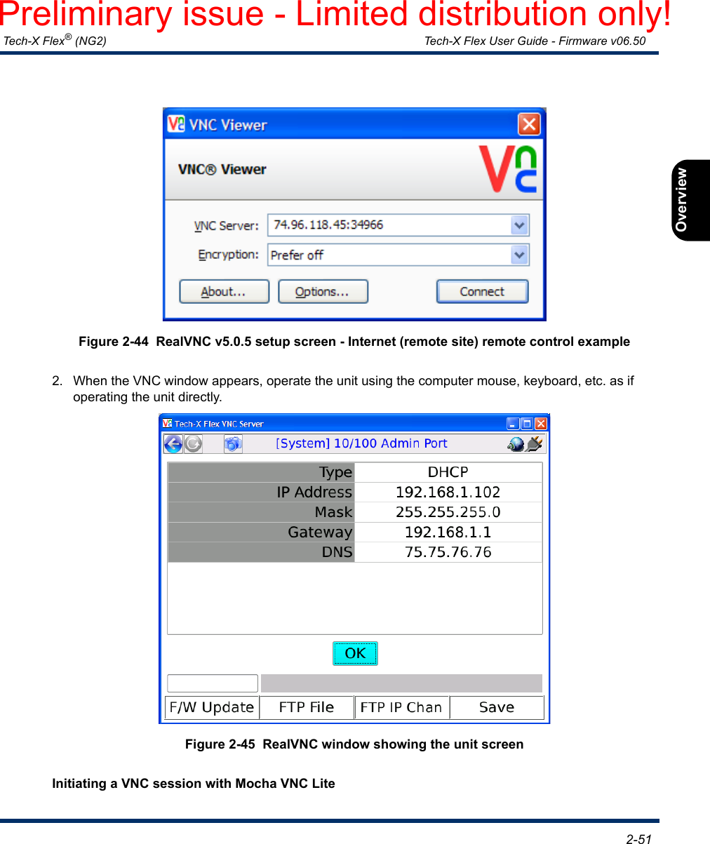
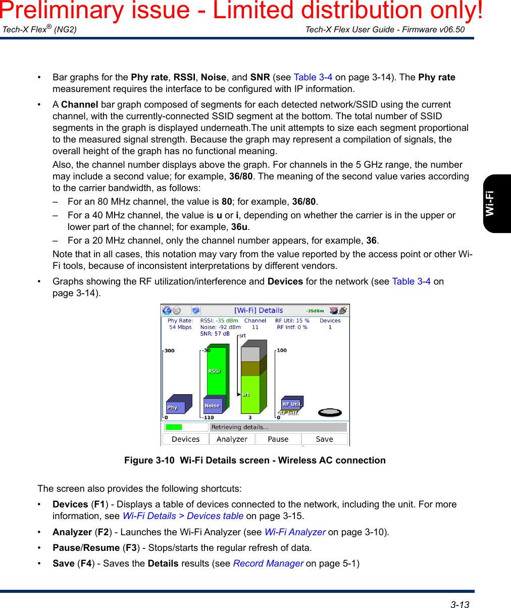
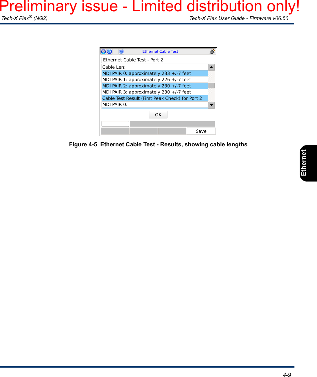
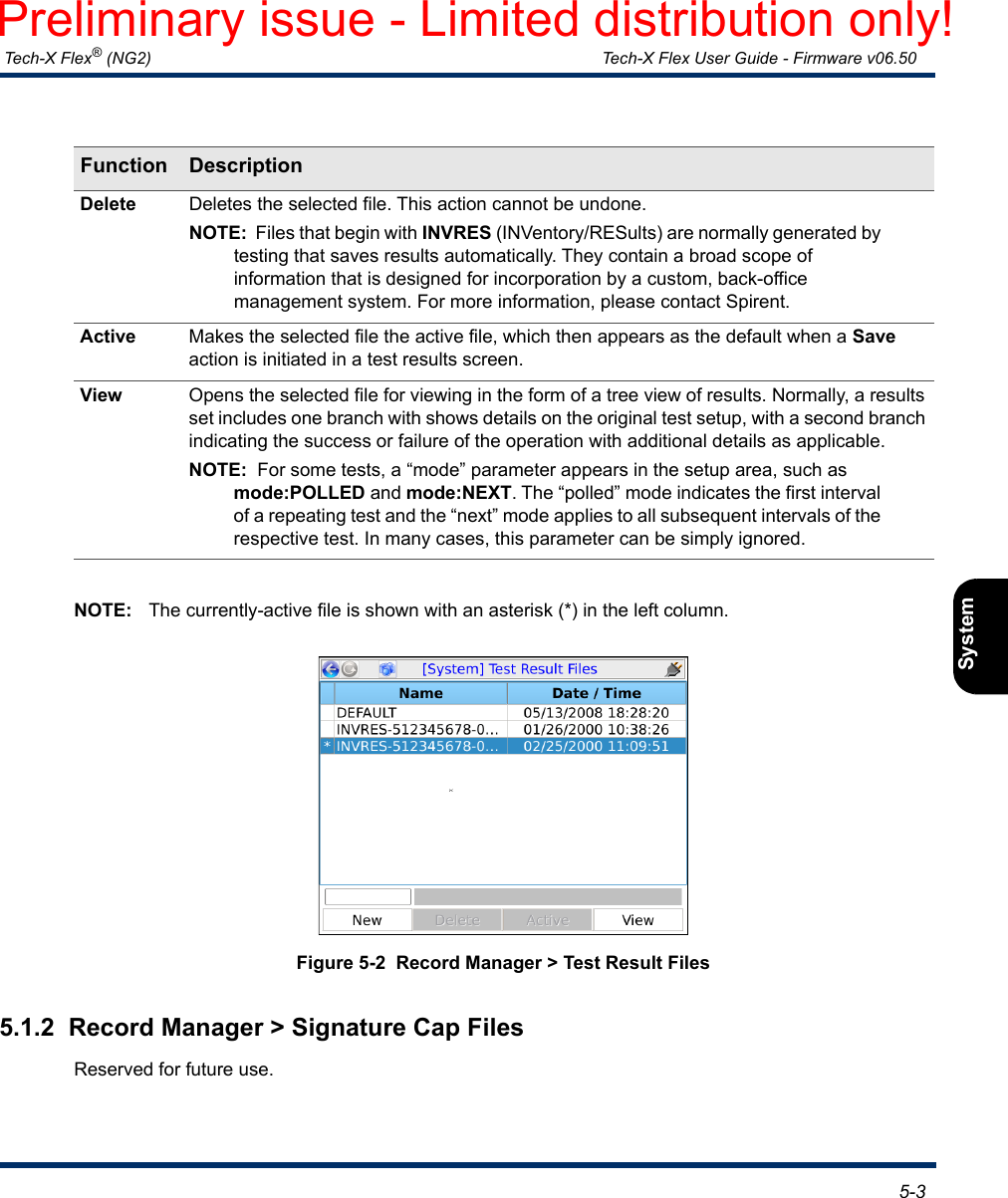
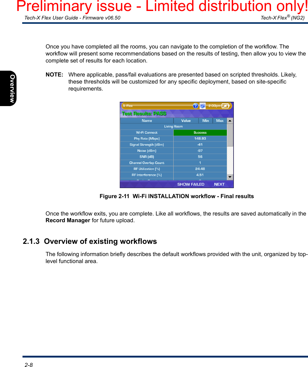
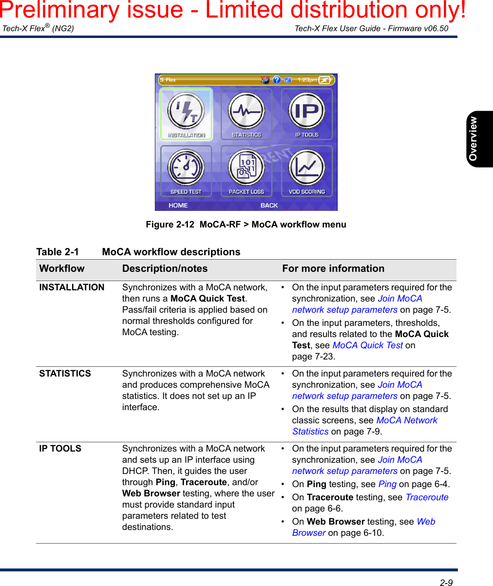
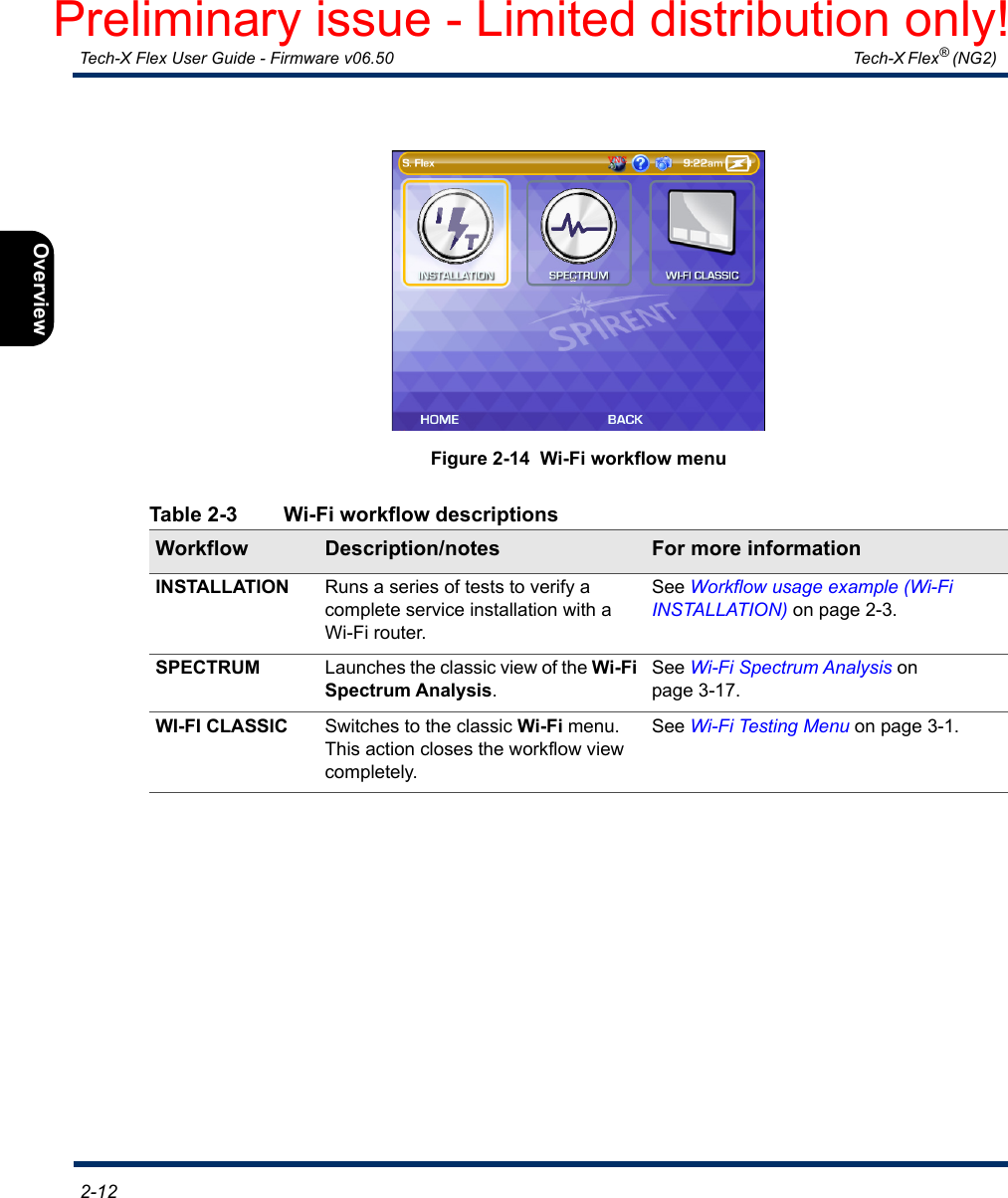
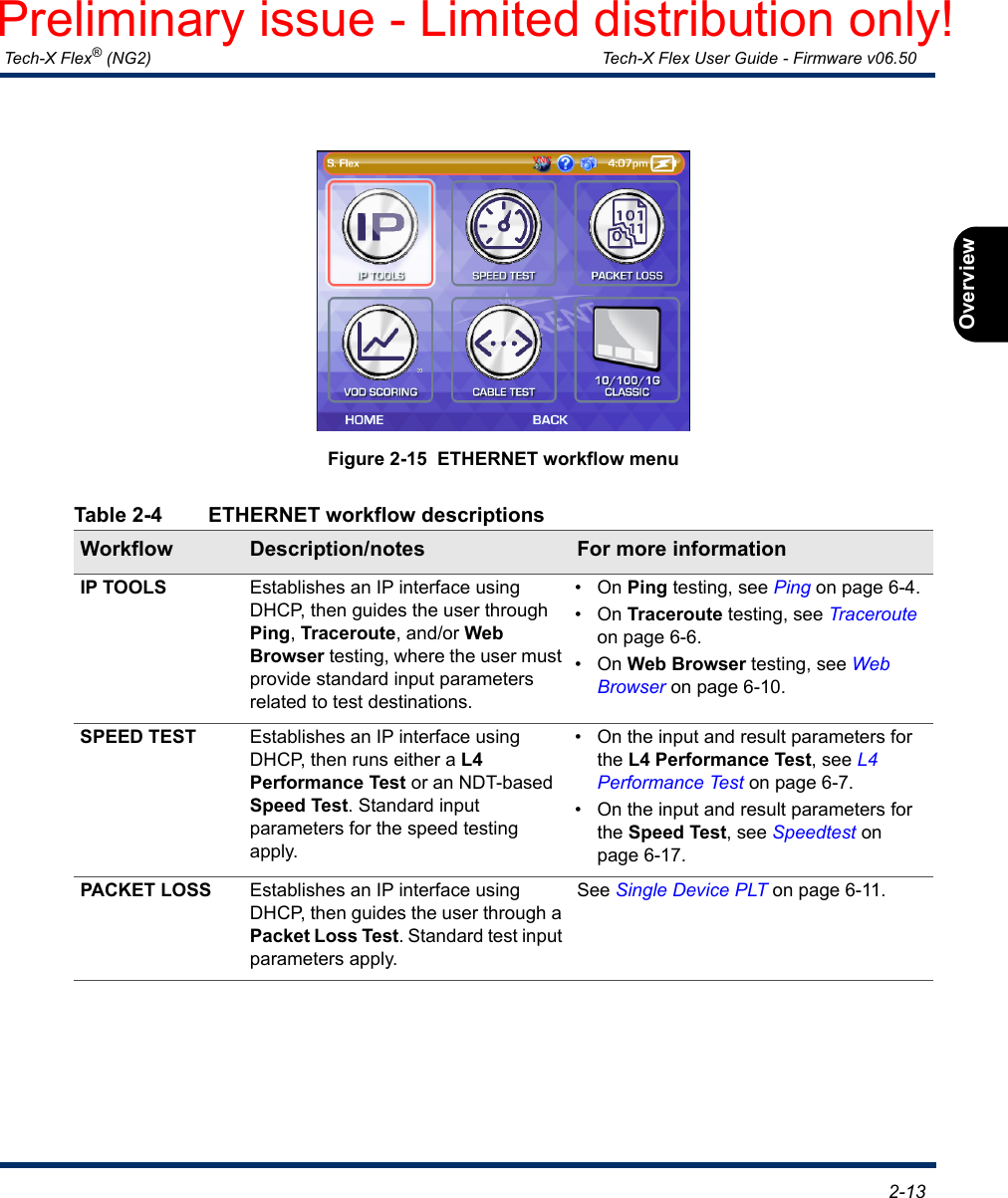
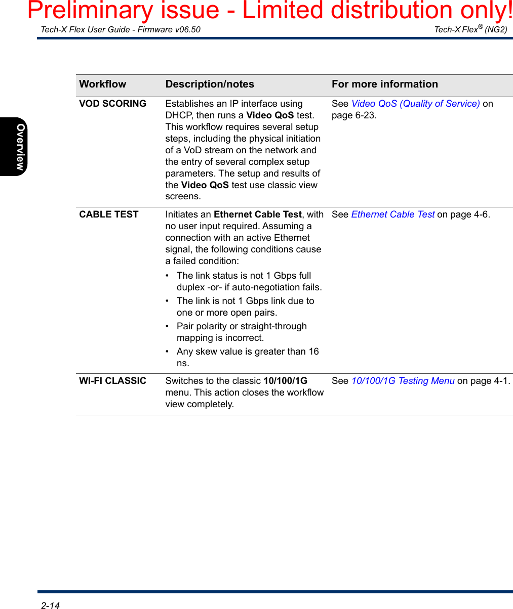
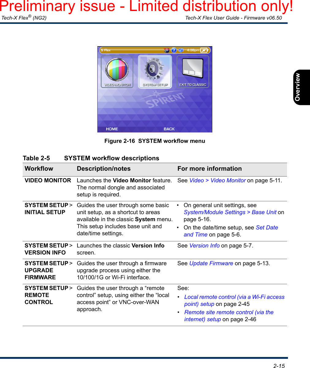
Spirent Communications FLEX-T5300 Tech-X Flex (NG2) User Manual Tech X Flex Manual
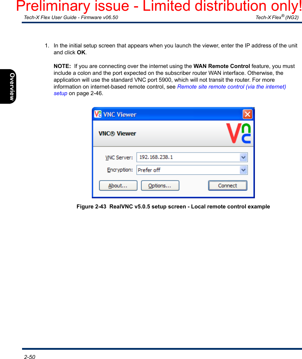
Spirent Communications Inc Tech-X Flex (NG2) Tech X Flex Manual
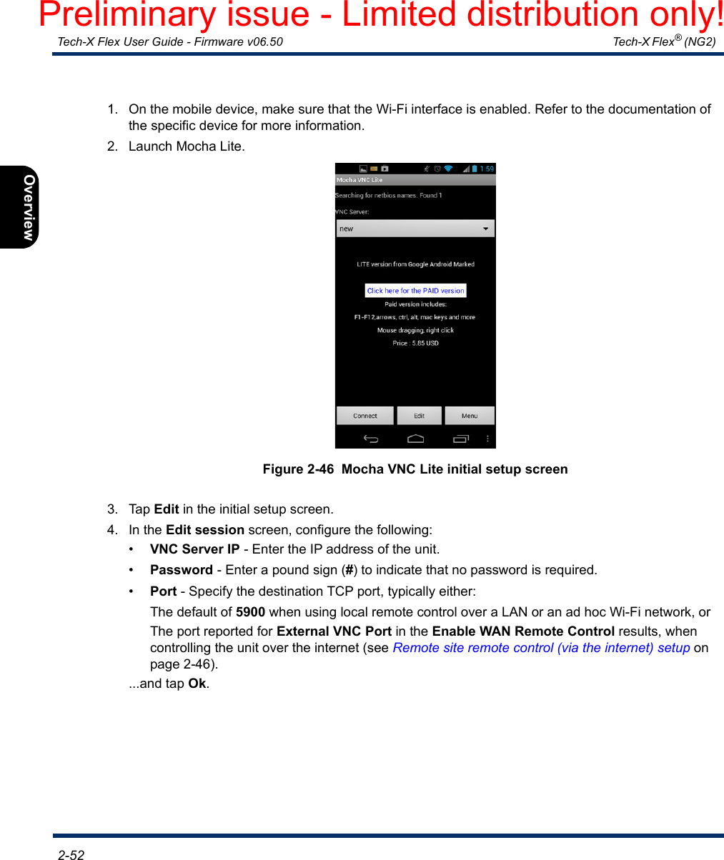
UserManual.wiki
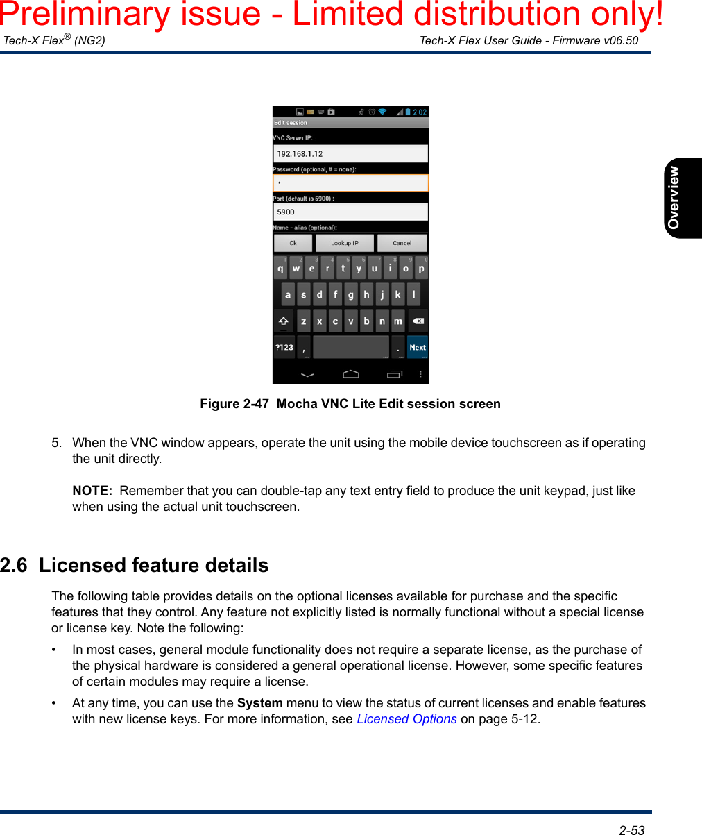
>
Spirent Communications
>
FLEX-T5300 User Manual
>
User Manual Part 1
Contents
1.
User Manual Part 1
2.
User Manual Part 2
User Manual Part 1
Navigation menu
Upload a User Manual
Namespaces
Wiki Guide
HTML
PDF
Info
Views
User Manual
Discussion / Help
Navigation

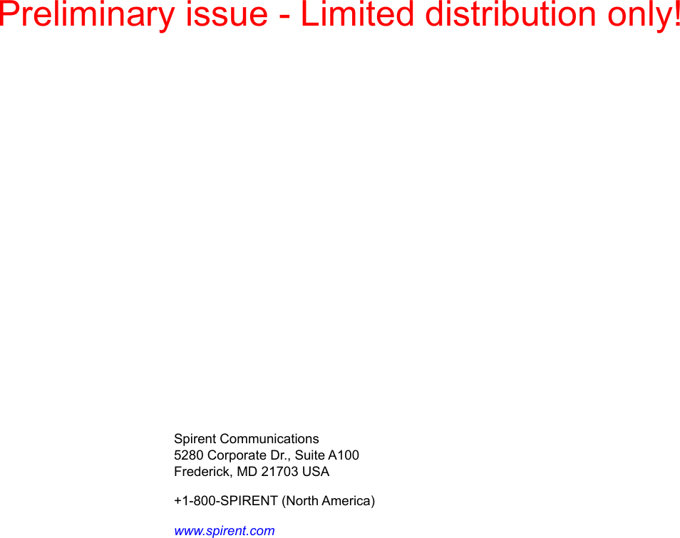


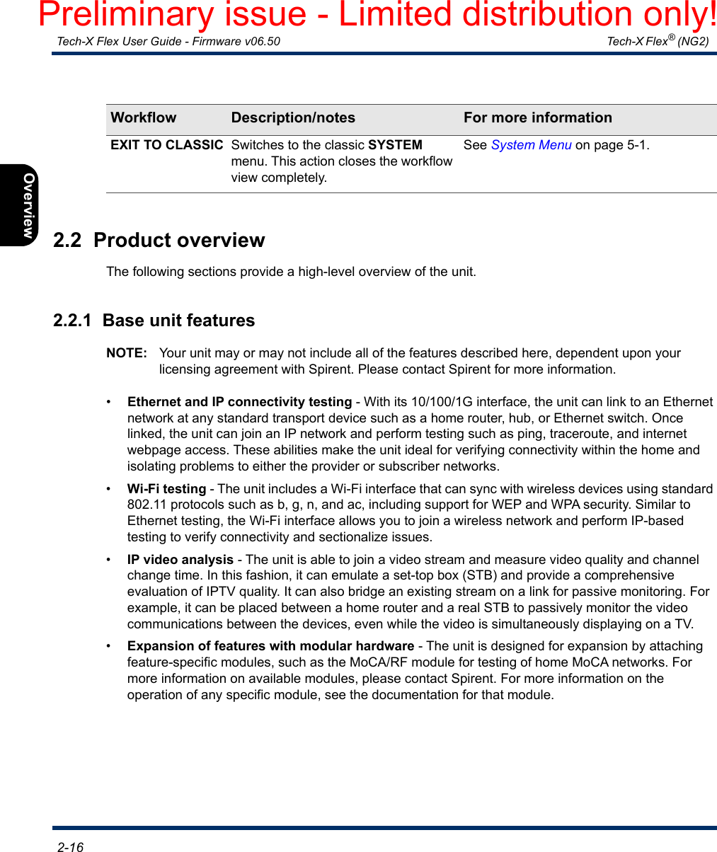
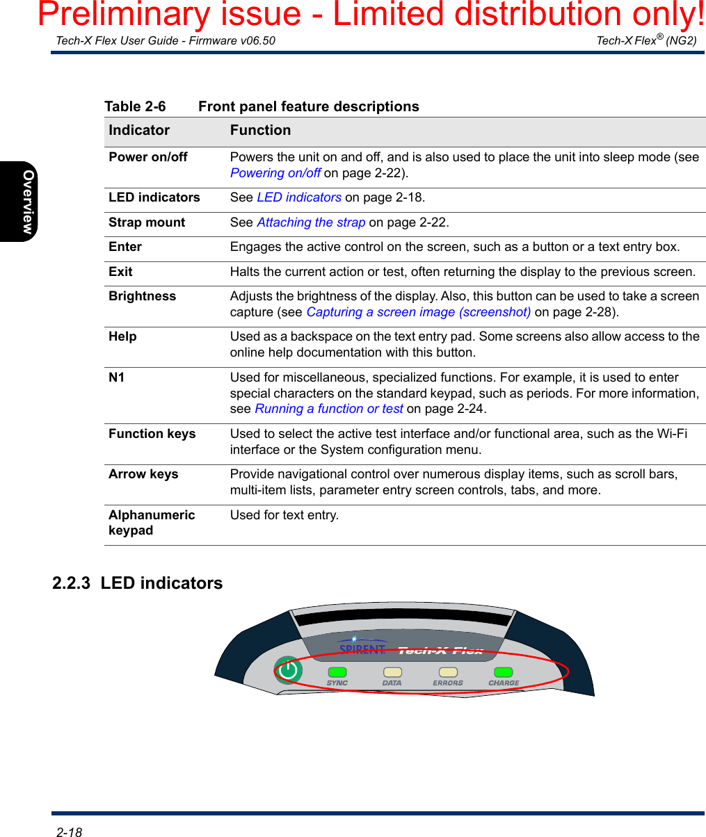
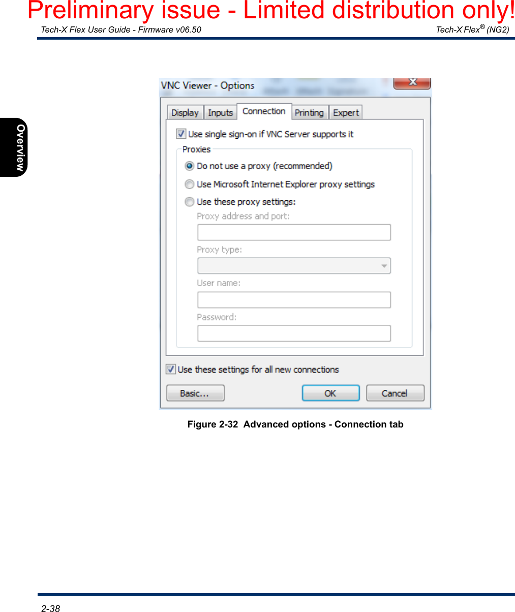
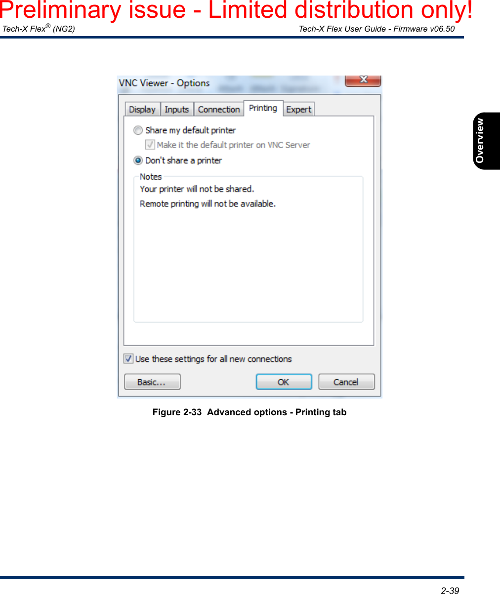
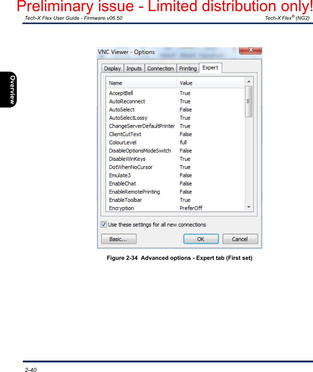
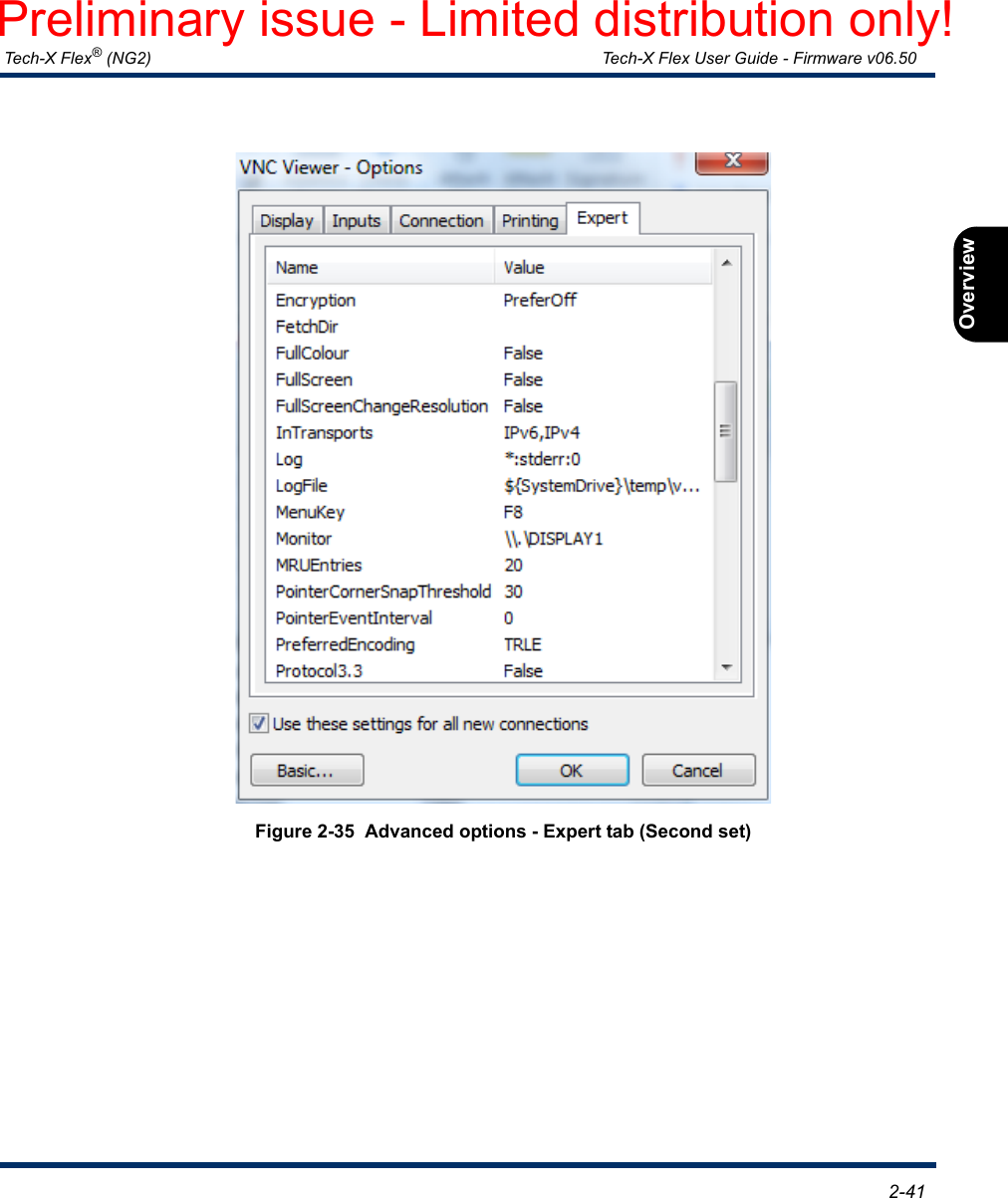
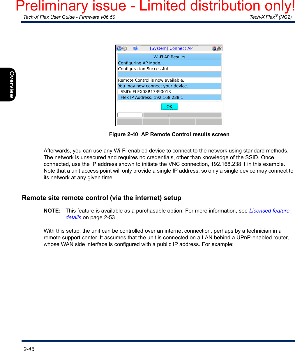
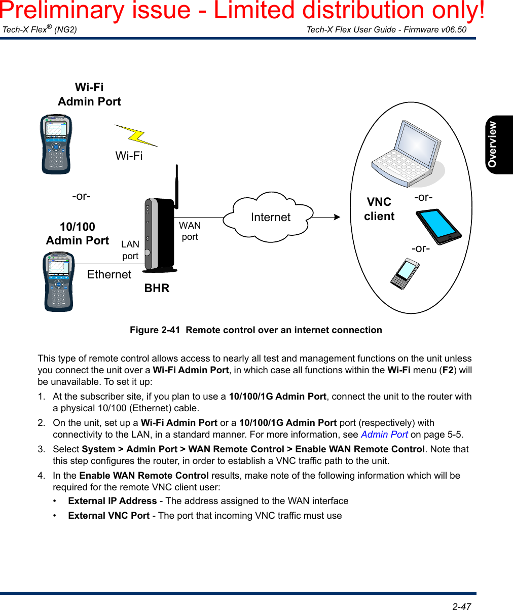
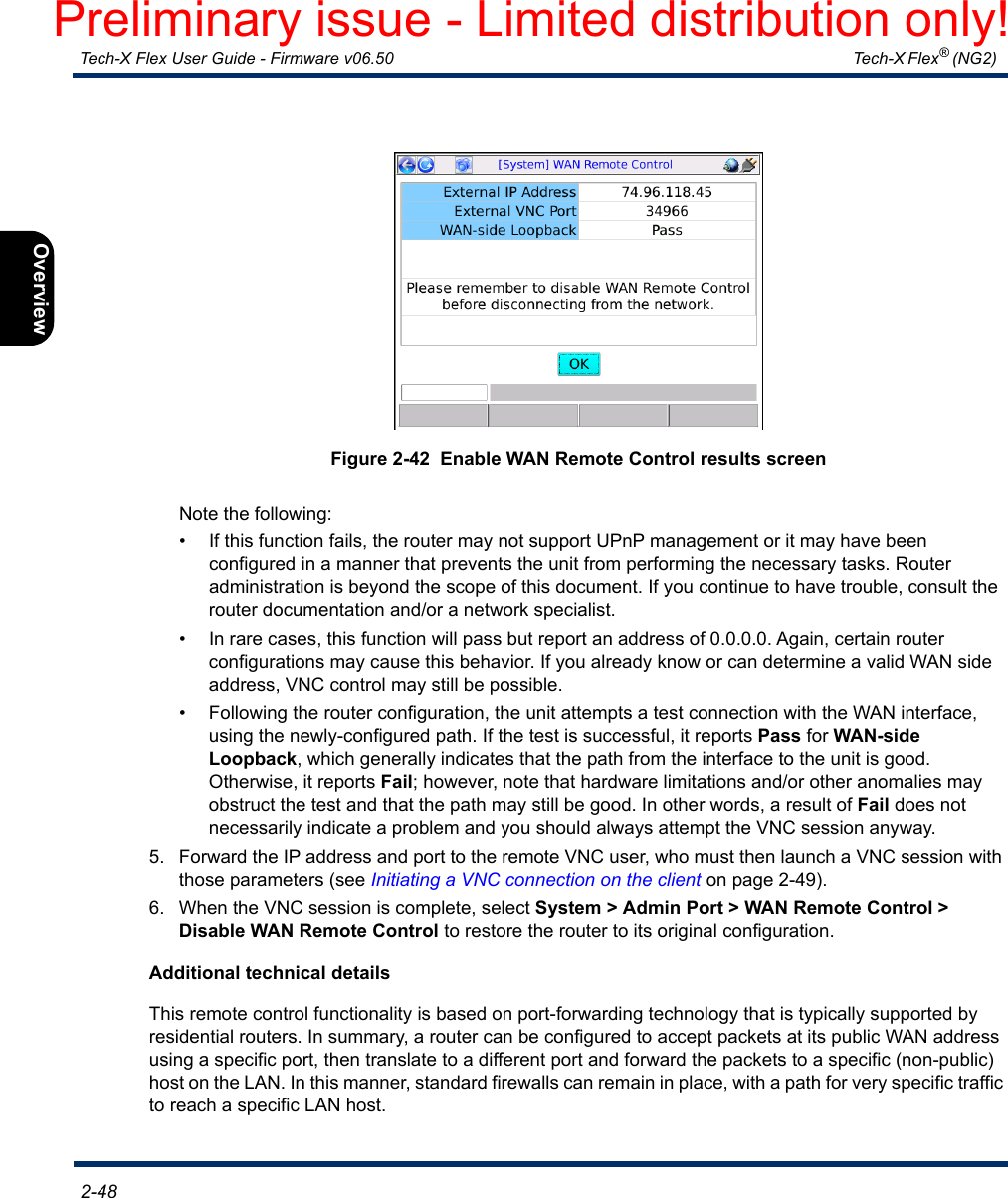
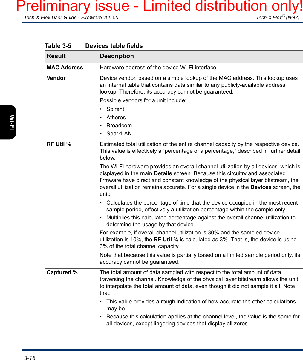
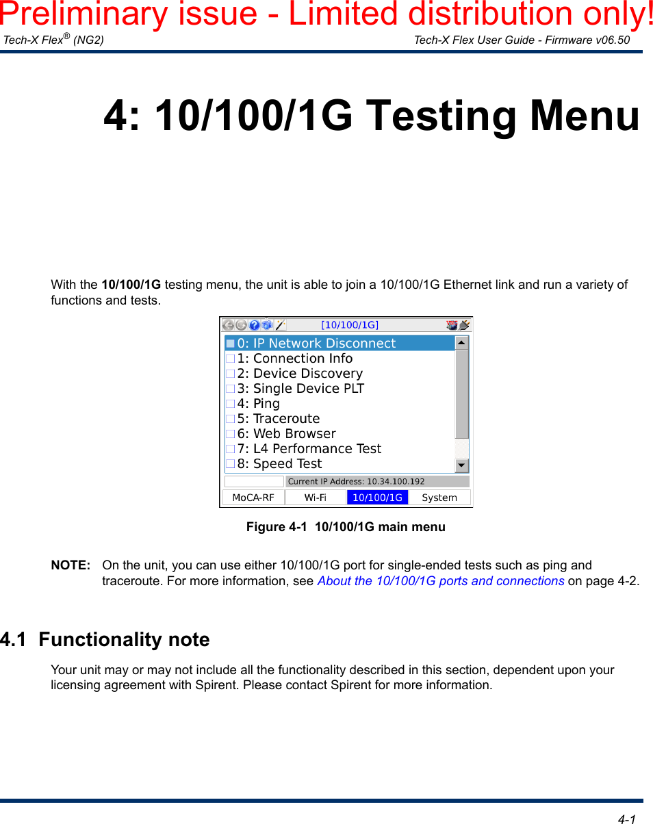
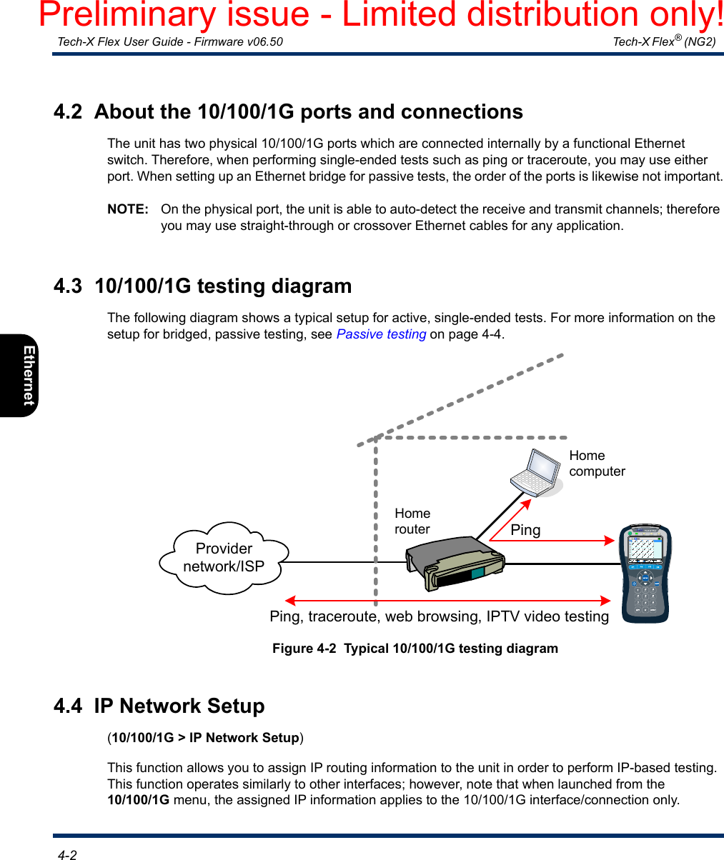
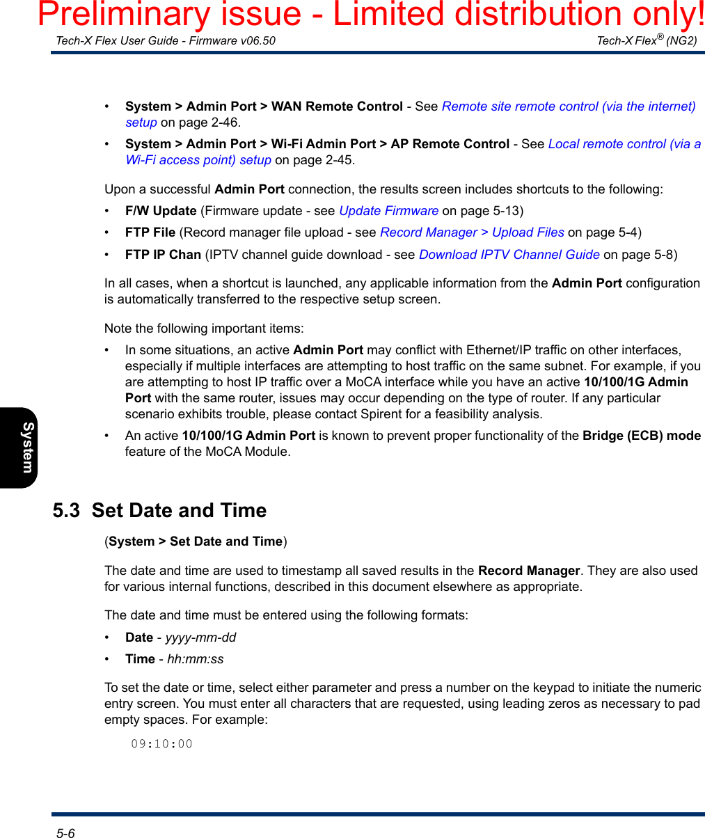
![Tech-X Flex® (NG2) Tech-X Flex User Guide - Firmware v06.50 2-17IntroOverviewWi-FiEthernetSystemIP/VideoMoCARFSpecs2.2.2 Front panel controlsFigure 2-17 Front panel controls6: Web Browser2: IP Network Setup3: Connection Info4: Ping5: Traceroute0: Wi-Fi Setup – 802.11bgnMoCA-RF Wi-Fi 10/100/1G System[Wi-Fi]7: Packet Loss Test8: Throughput1: Wi-Fi Setup – 802.11acTouchscreen displayPower on/off LED indicatorsFunction keysAlphanumeric keypad (physical)EnterExitBrightnessHelpN1Strap mountArrow keysPreliminary issue - Limited distribution only!](https://usermanual.wiki/Spirent-Communications/FLEX-T5300.User-Manual-Part-1/User-Guide-3054218-Page-39.png)