Spirent Communications FLEX-T5300 Tech-X Flex (NG2) User Manual Tech X Flex Manual
Spirent Communications Inc Tech-X Flex (NG2) Tech X Flex Manual
Contents
- 1. User Manual Part 1
- 2. User Manual Part 2
User Manual Part 1
Tech-X Flex® (NG2)
User Guide
June 01, 2016
Includes the base unit and optional MoCA/RF module
Supports firmware version v06.50
Preliminary issue - Limited distribution only!
Spirent Communications, Inc.
5280 Corporate Dr., Suite A100
Frederick, MD 21703
USA
1-800-SPIRENT (North America)
Copyright
© 2016 Spirent Communications, Inc. All Rights Reserved.
All of the company names and/or brand names and/or product names referred to in this document, in particular, the name “Spirent” and its logo device,
are either registered trademarks or trademarks of Spirent plc and its subsidiaries, pending registration in accordance with relevant national laws. All
other registered trademarks or trademarks are the property of their respective owners. The information contained in this document is subject to change
without notice and does not represent a commitment on the part of Spirent Communications. The information in this document is believed to be
accurate and reliable, however, Spirent Communications assumes no responsibility or liability for any errors or inaccuracies that may appear in the
document.
Limited Warranty - Hardware
“Hardware Warranty Period” shall refer to the period beginning upon the applicable Delivery Date of any Spirent Hardware purchased under this
Agreement and ending one (1) year thereafter; except (a) the Hardware Warranty Period for rechargeable batteries shall be ninety (90) days following
the applicable Delivery Date. Subject to the provisions hereof, Spirent warrants the Spirent Hardware during the Hardware Warranty Period against
material defects in material and workmanship and against failure to perform in substantial accordance with the published specifications therefore in the
Documentation (any such failure or defect, a “Hardware Defect”).
Sole Remedies. During the Hardware Warranty Period, as Customer’s sole remedy with respect to any and all Hardware Defects, Spirent will repair
or replace as provided any Spirent Hardware that proves to have a Hardware Defect. To obtain a warranty repair, Spirent Hardware allegedly
containing Hardware Defects must be returned for repair or replacement in accordance with Spirent’s return procedure. Spirent Hardware corrected or
replaced will also be warranted for the remainder of the original Hardware Warranty Period or sixty (60) days, whichever is the longer.. If Spirent
elects not to repair a Hardware Defect and not to replace the item of Spirent Hardware containing the Hardware Defect with respect to an item of
Spirent Hardware under warranty, Spirent will at its sole expense refund to Customer the purchase price of such Spirent Hardware
Reporting Period. The limited warranty set forth is subject to the restrictions set forth below and is contingent upon Customer notifying Spirent in
writing within ten (10) days following Customer’s discovery of any alleged Hardware Defect, and in no event later than ten (10) days after the end of
the Hardware Warranty Period.
Exclusions. The limited warranty set forth herein will not apply with respect to Hardware Defects caused by (a) neglect, accident, fire or other hazard,
damage or scratches to the screen, unauthorized alteration, modification, or repair, including without limitation, installation of unauthorized parts, (b)
improper testing, storage, operation, interconnection, or installation of the Spirent Hardware, (c) damage to the Spirent Hardware after the Delivery
Date, (d) damage to the Spirent Hardware or defects in the Spirent Hardware that was or should have been obvious to Customer upon a visual and
physical inspection thereof within the five-day period after the applicable Delivery Date, unless Customer has notified Spirent thereof during such
five-day period as provided in these Terms and Conditions, or (e) any other cause beyond the range of normal usage of the Spirent Hardware (except,
in all of the foregoing cases, when caused by Spirent or Spirent’s authorized agent). This limited warranty shall terminate upon any transfer or sale of
the Spirent Hardware by Customer. Spirent reserves the right to make changes in the design or construction of any of the Spirent Hardware at any time
without incurring any obligations to make any changes whatever on Spirent Hardware items previously purchased, unless Customer has subscribed for
a Service that requires the same.
Limited Warranty - Software
For a period of 1 year after the applicable Delivery Date, Spirent warrants that the Spirent Software shall perform in all material respects in accordance
with the applicable specifications therefore set forth in the Documentation. The foregoing limited warranty shall not apply to any Software
Malfunction which results from: (a) modification or installation of the Spirent Software by anyone other than Spirent or Spirent’s authorized agent, (b)
use of the Spirent Software for any purpose other than the intended use as reflected in the accompanying Documentation, (c) use of the Spirent
Software in combination with any other software or hardware not approved or expressly contemplated for use with such Spirent Software in the
Documentation if such claim would have been avoided but for such combination, (d) any misuse or incorrect use of the Spirent Software, or (e) any
malfunction in hardware that is not Spirent Hardware. Subject to the foregoing limitations, with respect to Spirent Software containing a Software
Malfunction, provided (A) Customer has notified Spirent in writing of the nature of the Software Malfunction during the applicable warranty period
and within ten (10) days after Customer’s discovery of the Software Malfunction, and (B) Spirent is able to verify such Software Malfunction, Spirent
will, at its expense, (i) correct such Spirent Software’s failure to conform to the warranty, (ii) replace such Spirent Software with Software meeting
Spirent’s then-current published specifications or (iii) terminate the licensed rights granted herein with respect to the applicable Spirent Software and
grant Customer a refund of the applicable license fee, less reasonable depreciation based on usage, which shall in no event be less than the result of a
straight-line computation based upon a three (3) year usable life..
Preliminary issue - Limited distribution only!
Tech-X Flex® (NG2)
Tech-X Flex User Guide -
Firmware v06.50
Preliminary issue - Limited distribution only!


Tech-X Flex® (NG2) Tech-X Flex User Guide - Firmware v06.50
-i
Contents
1: Introduction
1.1 Product purpose . . . . . . . . . . . . . . . . . . . . . . . . . . . . . . . . . . . . . . . . . . . . . . . 1-1
1.2 User prerequisites . . . . . . . . . . . . . . . . . . . . . . . . . . . . . . . . . . . . . . . . . . . . . 1-2
1.3 Documentation notes . . . . . . . . . . . . . . . . . . . . . . . . . . . . . . . . . . . . . . . . . . . 1-2
1.3.1 Firmware version support . . . . . . . . . . . . . . . . . . . . . . . . . . . . . . . . . . . . . . . . . . . . . 1-2
1.3.2 Document purpose and scope . . . . . . . . . . . . . . . . . . . . . . . . . . . . . . . . . . . . . . . . . . 1-2
1.3.3 Definitions of terms and acronyms . . . . . . . . . . . . . . . . . . . . . . . . . . . . . . . . . . . . . . 1-3
1.3.4 Additional documentation . . . . . . . . . . . . . . . . . . . . . . . . . . . . . . . . . . . . . . . . . . . . . 1-5
1.4 About hardware models and variations . . . . . . . . . . . . . . . . . . . . . . . . . . . . 1-5
1.5 Important safety notes . . . . . . . . . . . . . . . . . . . . . . . . . . . . . . . . . . . . . . . . . . 1-5
1.6 Consignes de sécurité importantes . . . . . . . . . . . . . . . . . . . . . . . . . . . . . . . 1-6
1.7 Documentation references. . . . . . . . . . . . . . . . . . . . . . . . . . . . . . . . . . . . . . . 1-6
1.8 Technical support . . . . . . . . . . . . . . . . . . . . . . . . . . . . . . . . . . . . . . . . . . . . . . 1-6
2: Product Overview
2.1 Introduction to the workflow interface . . . . . . . . . . . . . . . . . . . . . . . . . . . . . 2-1
2.1.1 About the workflow interface vs. the “classic” view . . . . . . . . . . . . . . . . . . . . . . . . . . 2-2
2.1.2 Workflow usage example (Wi-Fi INSTALLATION) . . . . . . . . . . . . . . . . . . . . . . . . . . 2-3
2.1.3 Overview of existing workflows . . . . . . . . . . . . . . . . . . . . . . . . . . . . . . . . . . . . . . . . . 2-8
2.2 Product overview . . . . . . . . . . . . . . . . . . . . . . . . . . . . . . . . . . . . . . . . . . . . . 2-16
2.2.1 Base unit features . . . . . . . . . . . . . . . . . . . . . . . . . . . . . . . . . . . . . . . . . . . . . . . . . . 2-16
2.2.2 Front panel controls . . . . . . . . . . . . . . . . . . . . . . . . . . . . . . . . . . . . . . . . . . . . . . . . . 2-17
2.2.3 LED indicators . . . . . . . . . . . . . . . . . . . . . . . . . . . . . . . . . . . . . . . . . . . . . . . . . . . . . 2-18
2.2.4 Base unit physical interfaces (ports) . . . . . . . . . . . . . . . . . . . . . . . . . . . . . . . . . . . . 2-20
Preliminary issue - Limited distribution only!

Tech-X Flex User Guide - Firmware v06.50 Tech-X Flex® (NG2)
-ii
Intro Overview Wi-Fi Ethernet System IP/Video MoCA RF Specs
2.2.5 Unit symbols . . . . . . . . . . . . . . . . . . . . . . . . . . . . . . . . . . . . . . . . . . . . . . . . . . . . . .2-21
2.3 General product handling and operation . . . . . . . . . . . . . . . . . . . . . . . . . . 2-21
2.3.1 Protection from water and dust ingress . . . . . . . . . . . . . . . . . . . . . . . . . . . . . . . . . .2-22
2.3.2 Important battery charging note . . . . . . . . . . . . . . . . . . . . . . . . . . . . . . . . . . . . . . . .2-22
2.3.3 Powering on/off . . . . . . . . . . . . . . . . . . . . . . . . . . . . . . . . . . . . . . . . . . . . . . . . . . . .2-22
2.3.4 Attaching the strap . . . . . . . . . . . . . . . . . . . . . . . . . . . . . . . . . . . . . . . . . . . . . . . . . .2-22
2.3.5 About the touchscreen display . . . . . . . . . . . . . . . . . . . . . . . . . . . . . . . . . . . . . . . . .2-24
2.3.6 Selecting the active interface . . . . . . . . . . . . . . . . . . . . . . . . . . . . . . . . . . . . . . . . . .2-24
2.3.7 Running a function or test . . . . . . . . . . . . . . . . . . . . . . . . . . . . . . . . . . . . . . . . . . . .2-24
2.3.8 Repeating a function or test . . . . . . . . . . . . . . . . . . . . . . . . . . . . . . . . . . . . . . . . . . .2-26
2.3.9 Screen title bar buttons/icons . . . . . . . . . . . . . . . . . . . . . . . . . . . . . . . . . . . . . . . . . .2-26
2.3.10 Capturing a screen image (screenshot) . . . . . . . . . . . . . . . . . . . . . . . . . . . . . . . . .2-28
2.3.11 Stopping a test . . . . . . . . . . . . . . . . . . . . . . . . . . . . . . . . . . . . . . . . . . . . . . . . . . . .2-29
2.3.12 Saving results . . . . . . . . . . . . . . . . . . . . . . . . . . . . . . . . . . . . . . . . . . . . . . . . . . . .2-29
2.3.13 Maximum test duration for continuous tests . . . . . . . . . . . . . . . . . . . . . . . . . . . . .2-29
2.3.14 Interpreting results . . . . . . . . . . . . . . . . . . . . . . . . . . . . . . . . . . . . . . . . . . . . . . . . .2-29
2.4 Handling the MoCA/RF module . . . . . . . . . . . . . . . . . . . . . . . . . . . . . . . . . . 2-30
2.4.1 Attaching, detaching, and handling the module . . . . . . . . . . . . . . . . . . . . . . . . . . . .2-30
2.4.2 Connecting the module to the coax network . . . . . . . . . . . . . . . . . . . . . . . . . . . . . .2-32
2.4.3 How to attach/replace the coax port adapters . . . . . . . . . . . . . . . . . . . . . . . . . . . . .2-32
2.4.4 Which coaxial port to use . . . . . . . . . . . . . . . . . . . . . . . . . . . . . . . . . . . . . . . . . . . . .2-32
2.4.5 SYNC LED behavior . . . . . . . . . . . . . . . . . . . . . . . . . . . . . . . . . . . . . . . . . . . . . . . .2-33
2.4.6 Calibration requirements . . . . . . . . . . . . . . . . . . . . . . . . . . . . . . . . . . . . . . . . . . . . .2-33
2.5 Remote control of the unit . . . . . . . . . . . . . . . . . . . . . . . . . . . . . . . . . . . . . . 2-33
2.5.1 About VNC . . . . . . . . . . . . . . . . . . . . . . . . . . . . . . . . . . . . . . . . . . . . . . . . . . . . . . . .2-34
2.5.2 Installing a VNC client (viewer) . . . . . . . . . . . . . . . . . . . . . . . . . . . . . . . . . . . . . . . .2-34
RealVNC 4.1.3 installation and setup . . . . . . . . . . . . . . . . . . . . . . . . . . . . . . . . . . . . . .2-35
RealVNC 5.0.5 installation and setup . . . . . . . . . . . . . . . . . . . . . . . . . . . . . . . . . . . . . .2-35
2.5.3 Remote control setup scenarios . . . . . . . . . . . . . . . . . . . . . . . . . . . . . . . . . . . . . . .2-43
Local remote control (via a router/LAN) setup . . . . . . . . . . . . . . . . . . . . . . . . . . . . . . .2-44
Local remote control (via a Wi-Fi access point) setup . . . . . . . . . . . . . . . . . . . . . . . . .2-45
Remote site remote control (via the internet) setup . . . . . . . . . . . . . . . . . . . . . . . . . . .2-46
2.5.4 Initiating a VNC connection on the client . . . . . . . . . . . . . . . . . . . . . . . . . . . . . . . . .2-49
2.6 Licensed feature details . . . . . . . . . . . . . . . . . . . . . . . . . . . . . . . . . . . . . . . . 2-53
2.7 Maintenance . . . . . . . . . . . . . . . . . . . . . . . . . . . . . . . . . . . . . . . . . . . . . . . . . . 2-55
Preliminary issue - Limited distribution only!

Tech-X Flex® (NG2) Tech-X Flex User Guide - Firmware v06.50
-iii
Intro
Overview
Wi-Fi
Ethernet
System
IP/Video
MoCA
RF
Specs
2.7.1 Battery installation/replacement . . . . . . . . . . . . . . . . . . . . . . . . . . . . . . . . . . . . . . . 2-55
2.8 FTP information . . . . . . . . . . . . . . . . . . . . . . . . . . . . . . . . . . . . . . . . . . . . . . 2-57
2.8.1 Admin Port setup . . . . . . . . . . . . . . . . . . . . . . . . . . . . . . . . . . . . . . . . . . . . . . . . . . 2-57
2.8.2 FTP server installation and setup . . . . . . . . . . . . . . . . . . . . . . . . . . . . . . . . . . . . . . 2-58
2.8.3 FTP connection parameters . . . . . . . . . . . . . . . . . . . . . . . . . . . . . . . . . . . . . . . . . . 2-59
2.8.4 FTP connection troubleshooting . . . . . . . . . . . . . . . . . . . . . . . . . . . . . . . . . . . . . . . 2-61
2.9 Technical support . . . . . . . . . . . . . . . . . . . . . . . . . . . . . . . . . . . . . . . . . . . . . 2-61
3: Wi-Fi Testing Menu
3.1 Important wireless 802.11ac note (T5100 models only) . . . . . . . . . . . . . . . 3-2
3.2 Functionality note . . . . . . . . . . . . . . . . . . . . . . . . . . . . . . . . . . . . . . . . . . . . . . 3-2
3.3 Wi-Fi overview. . . . . . . . . . . . . . . . . . . . . . . . . . . . . . . . . . . . . . . . . . . . . . . . . 3-2
3.3.1 Wi-Fi support details . . . . . . . . . . . . . . . . . . . . . . . . . . . . . . . . . . . . . . . . . . . . . . . . . 3-2
3.3.2 Wi-Fi testing diagram . . . . . . . . . . . . . . . . . . . . . . . . . . . . . . . . . . . . . . . . . . . . . . . . . 3-3
3.3.3 If you cannot connect (troubleshooting tips) . . . . . . . . . . . . . . . . . . . . . . . . . . . . . . . 3-4
3.3.4 About WPS support . . . . . . . . . . . . . . . . . . . . . . . . . . . . . . . . . . . . . . . . . . . . . . . . . . 3-4
3.4 Wi-Fi Setup . . . . . . . . . . . . . . . . . . . . . . . . . . . . . . . . . . . . . . . . . . . . . . . . . . . 3-5
3.4.1 Wi-Fi Setup > Scan . . . . . . . . . . . . . . . . . . . . . . . . . . . . . . . . . . . . . . . . . . . . . . . . . 3-5
Setup - Scan (Wi-Fi Setup) . . . . . . . . . . . . . . . . . . . . . . . . . . . . . . . . . . . . . . . . . . . . . . 3-5
Results - Scan (Wi-Fi Setup) . . . . . . . . . . . . . . . . . . . . . . . . . . . . . . . . . . . . . . . . . . . . 3-6
3.4.2 Wi-Fi Setup > Connect . . . . . . . . . . . . . . . . . . . . . . . . . . . . . . . . . . . . . . . . . . . . . . 3-7
Setup - Connect (Wi-Fi Setup) . . . . . . . . . . . . . . . . . . . . . . . . . . . . . . . . . . . . . . . . . . . 3-7
Results - Connect (Wi-Fi Setup) . . . . . . . . . . . . . . . . . . . . . . . . . . . . . . . . . . . . . . . . . 3-10
3.4.3 Wi-Fi Analyzer . . . . . . . . . . . . . . . . . . . . . . . . . . . . . . . . . . . . . . . . . . . . . . . . . . . . . 3-10
3.5 Wi-Fi Details . . . . . . . . . . . . . . . . . . . . . . . . . . . . . . . . . . . . . . . . . . . . . . . . . 3-11
3.5.1 Wi-Fi Details > Devices table . . . . . . . . . . . . . . . . . . . . . . . . . . . . . . . . . . . . . . . . . 3-15
3.6 Wi-Fi Spectrum Analysis . . . . . . . . . . . . . . . . . . . . . . . . . . . . . . . . . . . . . . . 3-17
3.7 IP Testing > IP Network Setup . . . . . . . . . . . . . . . . . . . . . . . . . . . . . . . . . . . 3-18
3.8 IP Testing options over Wi-Fi . . . . . . . . . . . . . . . . . . . . . . . . . . . . . . . . . . . 3-18
4: 10/100/1G Testing Menu
4.1 Functionality note . . . . . . . . . . . . . . . . . . . . . . . . . . . . . . . . . . . . . . . . . . . . . . 4-1
4.2 About the 10/100/1G ports and connections . . . . . . . . . . . . . . . . . . . . . . . . 4-2
Preliminary issue - Limited distribution only!

Tech-X Flex User Guide - Firmware v06.50 Tech-X Flex® (NG2)
-iv
Intro Overview Wi-Fi Ethernet System IP/Video MoCA RF Specs
4.3 10/100/1G testing diagram . . . . . . . . . . . . . . . . . . . . . . . . . . . . . . . . . . . . . . . 4-2
4.4 IP Network Setup . . . . . . . . . . . . . . . . . . . . . . . . . . . . . . . . . . . . . . . . . . . . . . . 4-2
4.5 IP testing options over Ethernet . . . . . . . . . . . . . . . . . . . . . . . . . . . . . . . . . . 4-3
4.6 Passive testing. . . . . . . . . . . . . . . . . . . . . . . . . . . . . . . . . . . . . . . . . . . . . . . . . 4-4
4.6.1 Unit setup for passive testing . . . . . . . . . . . . . . . . . . . . . . . . . . . . . . . . . . . . . . . . . . .4-4
4.6.2 Passive Video QoS (Quality of Service) . . . . . . . . . . . . . . . . . . . . . . . . . . . . . . . . . .4-5
4.7 Ethernet Cable Test . . . . . . . . . . . . . . . . . . . . . . . . . . . . . . . . . . . . . . . . . . . . . 4-6
4.7.1 Setup - Ethernet Cable Test . . . . . . . . . . . . . . . . . . . . . . . . . . . . . . . . . . . . . . . . . . .4-6
4.7.2 Results - Ethernet Cable Test . . . . . . . . . . . . . . . . . . . . . . . . . . . . . . . . . . . . . . . . .4-7
5: System Menu
5.1 Record Manager. . . . . . . . . . . . . . . . . . . . . . . . . . . . . . . . . . . . . . . . . . . . . . . . 5-1
5.1.1 Record Manager > Test Result Files . . . . . . . . . . . . . . . . . . . . . . . . . . . . . . . . . . .5-2
5.1.2 Record Manager > Signature Cap Files . . . . . . . . . . . . . . . . . . . . . . . . . . . . . . . . .5-3
5.1.3 Record Manager > Screen Capture Files . . . . . . . . . . . . . . . . . . . . . . . . . . . . . . . .5-4
5.1.4 Record Manager > Upload Files . . . . . . . . . . . . . . . . . . . . . . . . . . . . . . . . . . . . . . .5-4
5.2 Admin Port . . . . . . . . . . . . . . . . . . . . . . . . . . . . . . . . . . . . . . . . . . . . . . . . . . . . 5-5
5.3 Set Date and Time . . . . . . . . . . . . . . . . . . . . . . . . . . . . . . . . . . . . . . . . . . . . . . 5-6
5.4 Version Info . . . . . . . . . . . . . . . . . . . . . . . . . . . . . . . . . . . . . . . . . . . . . . . . . . . 5-7
5.5 Battery Status . . . . . . . . . . . . . . . . . . . . . . . . . . . . . . . . . . . . . . . . . . . . . . . . . 5-8
5.6 Video . . . . . . . . . . . . . . . . . . . . . . . . . . . . . . . . . . . . . . . . . . . . . . . . . . . . . . . . . 5-8
5.6.1 Download IPTV Channel Guide . . . . . . . . . . . . . . . . . . . . . . . . . . . . . . . . . . . . . . .5-8
File preparation and general handling notes . . . . . . . . . . . . . . . . . . . . . . . . . . . . . . . . .5-9
Download procedure . . . . . . . . . . . . . . . . . . . . . . . . . . . . . . . . . . . . . . . . . . . . . . . . . . . .5-9
5.6.2 Video > View/Edit Thresholds . . . . . . . . . . . . . . . . . . . . . . . . . . . . . . . . . . . . . . . . .5-9
5.6.3 Video > Download Thresholds . . . . . . . . . . . . . . . . . . . . . . . . . . . . . . . . . . . . . . .5-10
5.6.4 Video > Video Monitor . . . . . . . . . . . . . . . . . . . . . . . . . . . . . . . . . . . . . . . . . . . . . .5-11
5.7 Cal Touchscreen . . . . . . . . . . . . . . . . . . . . . . . . . . . . . . . . . . . . . . . . . . . . . . 5-12
5.8 Licensed Options. . . . . . . . . . . . . . . . . . . . . . . . . . . . . . . . . . . . . . . . . . . . . . 5-12
5.9 Update Firmware . . . . . . . . . . . . . . . . . . . . . . . . . . . . . . . . . . . . . . . . . . . . . . 5-13
5.10 System/Module Settings . . . . . . . . . . . . . . . . . . . . . . . . . . . . . . . . . . . . . . . 5-15
5.10.1 System/Module Settings > Base Unit . . . . . . . . . . . . . . . . . . . . . . . . . . . . . . . . .5-16
Preliminary issue - Limited distribution only!

Tech-X Flex® (NG2) Tech-X Flex User Guide - Firmware v06.50
-v
Intro
Overview
Wi-Fi
Ethernet
System
IP/Video
MoCA
RF
Specs
5.10.2 System/Module Settings > RF Video Module . . . . . . . . . . . . . . . . . . . . . . . . . . 5-17
5.10.3 System/Module Settings > ADSL/VDSL2 Module . . . . . . . . . . . . . . . . . . . . . . . 5-17
5.10.4 System/Module Settings > Combined Module Default . . . . . . . . . . . . . . . . . . . 5-17
5.10.5 System/Module Settings > MoCA Module . . . . . . . . . . . . . . . . . . . . . . . . . . . . . 5-17
5.10.6 System/Module Settings > DOCSIS Module . . . . . . . . . . . . . . . . . . . . . . . . . . . 5-17
5.10.7 System/Module Settings > CSM Module . . . . . . . . . . . . . . . . . . . . . . . . . . . . . . 5-18
5.10.8 System/Module Settings > MoCA-RF Module . . . . . . . . . . . . . . . . . . . . . . . . . . 5-18
5.10.9 System/Module Settings > Wi-Fi . . . . . . . . . . . . . . . . . . . . . . . . . . . . . . . . . . . . 5-18
5.11 Signature Capture. . . . . . . . . . . . . . . . . . . . . . . . . . . . . . . . . . . . . . . . . . . . 5-18
5.12 Language Selection . . . . . . . . . . . . . . . . . . . . . . . . . . . . . . . . . . . . . . . . . . 5-18
5.13 Help and Support . . . . . . . . . . . . . . . . . . . . . . . . . . . . . . . . . . . . . . . . . . . . 5-18
5.14 System Information . . . . . . . . . . . . . . . . . . . . . . . . . . . . . . . . . . . . . . . . . . 5-19
5.15 Wizard GUI. . . . . . . . . . . . . . . . . . . . . . . . . . . . . . . . . . . . . . . . . . . . . . . . . . 5-19
6: IP and Video Testing
6.1 IP Network Setup . . . . . . . . . . . . . . . . . . . . . . . . . . . . . . . . . . . . . . . . . . . . . . 6-1
6.1.1 Setup - IP Network Setup . . . . . . . . . . . . . . . . . . . . . . . . . . . . . . . . . . . . . . . . . . . . 6-2
6.1.2 Results - IP Network Setup . . . . . . . . . . . . . . . . . . . . . . . . . . . . . . . . . . . . . . . . . . . 6-3
6.1.3 DHCP troubleshooting tips . . . . . . . . . . . . . . . . . . . . . . . . . . . . . . . . . . . . . . . . . . . . 6-4
6.2 Connection Info. . . . . . . . . . . . . . . . . . . . . . . . . . . . . . . . . . . . . . . . . . . . . . . . 6-4
6.3 Ping . . . . . . . . . . . . . . . . . . . . . . . . . . . . . . . . . . . . . . . . . . . . . . . . . . . . . . . . . 6-4
6.3.1 Setup - Ping . . . . . . . . . . . . . . . . . . . . . . . . . . . . . . . . . . . . . . . . . . . . . . . . . . . . . . . 6-5
6.3.2 Results - Ping . . . . . . . . . . . . . . . . . . . . . . . . . . . . . . . . . . . . . . . . . . . . . . . . . . . . . . 6-5
6.4 Traceroute . . . . . . . . . . . . . . . . . . . . . . . . . . . . . . . . . . . . . . . . . . . . . . . . . . . . 6-6
6.4.1 Setup - Traceroute test . . . . . . . . . . . . . . . . . . . . . . . . . . . . . . . . . . . . . . . . . . . . . . . 6-6
6.4.2 Results - Traceroute test . . . . . . . . . . . . . . . . . . . . . . . . . . . . . . . . . . . . . . . . . . . . . 6-6
6.5 L4 Performance Test . . . . . . . . . . . . . . . . . . . . . . . . . . . . . . . . . . . . . . . . . . . 6-7
6.5.1 Setup - L4 Performance Test . . . . . . . . . . . . . . . . . . . . . . . . . . . . . . . . . . . . . . . . . 6-7
6.5.2 Results - L4 Performance Test . . . . . . . . . . . . . . . . . . . . . . . . . . . . . . . . . . . . . . . . 6-8
6.6 Web Browser . . . . . . . . . . . . . . . . . . . . . . . . . . . . . . . . . . . . . . . . . . . . . . . . . 6-10
6.6.1 Setup - Web Browser . . . . . . . . . . . . . . . . . . . . . . . . . . . . . . . . . . . . . . . . . . . . . . . 6-11
6.7 Single Device PLT. . . . . . . . . . . . . . . . . . . . . . . . . . . . . . . . . . . . . . . . . . . . . 6-11
6.7.1 Setup - Single Device PLT . . . . . . . . . . . . . . . . . . . . . . . . . . . . . . . . . . . . . . . . . . . 6-12
Preliminary issue - Limited distribution only!

Tech-X Flex User Guide - Firmware v06.50 Tech-X Flex® (NG2)
-vi
Intro Overview Wi-Fi Ethernet System IP/Video MoCA RF Specs
6.7.2 Results - Single Device PLT . . . . . . . . . . . . . . . . . . . . . . . . . . . . . . . . . . . . . . . . . .6-12
6.8 Throughput. . . . . . . . . . . . . . . . . . . . . . . . . . . . . . . . . . . . . . . . . . . . . . . . . . . 6-14
6.8.1 Setup - Throughput . . . . . . . . . . . . . . . . . . . . . . . . . . . . . . . . . . . . . . . . . . . . . . . .6-14
6.8.2 Results - Throughput . . . . . . . . . . . . . . . . . . . . . . . . . . . . . . . . . . . . . . . . . . . . . . .6-15
6.8.3 Throughput server setup . . . . . . . . . . . . . . . . . . . . . . . . . . . . . . . . . . . . . . . . . . . .6-16
6.9 Speedtest . . . . . . . . . . . . . . . . . . . . . . . . . . . . . . . . . . . . . . . . . . . . . . . . . . . . 6-17
6.9.1 Setup - Speedtest . . . . . . . . . . . . . . . . . . . . . . . . . . . . . . . . . . . . . . . . . . . . . . . . . .6-17
6.9.2 Results - Speedtest . . . . . . . . . . . . . . . . . . . . . . . . . . . . . . . . . . . . . . . . . . . . . . . . .6-18
6.10 All Devices Packet Loss (Device Discovery) . . . . . . . . . . . . . . . . . . . . . . 6-19
6.10.1 Setup - All Devices Packet Loss . . . . . . . . . . . . . . . . . . . . . . . . . . . . . . . . . . . . .6-19
6.10.2 Results - All Devices Packet Loss . . . . . . . . . . . . . . . . . . . . . . . . . . . . . . . . . . . .6-20
6.10.3 Special MoCA BHR considerations - All Devices Packet Loss . . . . . . . . . . . . . .6-21
6.11 IP Video testing . . . . . . . . . . . . . . . . . . . . . . . . . . . . . . . . . . . . . . . . . . . . . . 6-22
6.11.1 Video QoS (Quality of Service) . . . . . . . . . . . . . . . . . . . . . . . . . . . . . . . . . . . . . . .6-23
Setup - Video QoS . . . . . . . . . . . . . . . . . . . . . . . . . . . . . . . . . . . . . . . . . . . . . . . . . . . .6-24
Results - Video QoS (MDI test) . . . . . . . . . . . . . . . . . . . . . . . . . . . . . . . . . . . . . . . . . .6-30
Results - Video QoS (VQM test) . . . . . . . . . . . . . . . . . . . . . . . . . . . . . . . . . . . . . . . . .6-31
Digital video concepts overview . . . . . . . . . . . . . . . . . . . . . . . . . . . . . . . . . . . . . . . . . .6-39
Video quality measurement (VQM) overview and additional results descriptions . . . .6-45
MDI measurement overview . . . . . . . . . . . . . . . . . . . . . . . . . . . . . . . . . . . . . . . . . . . . .6-48
Additional video testing notes . . . . . . . . . . . . . . . . . . . . . . . . . . . . . . . . . . . . . . . . . . . .6-50
6.11.2 Change Channel . . . . . . . . . . . . . . . . . . . . . . . . . . . . . . . . . . . . . . . . . . . . . . . . . .6-51
Setup - Change Channel . . . . . . . . . . . . . . . . . . . . . . . . . . . . . . . . . . . . . . . . . . . . . . .6-51
Results - Change Channel . . . . . . . . . . . . . . . . . . . . . . . . . . . . . . . . . . . . . . . . . . . . .6-52
How channel change time is calculated . . . . . . . . . . . . . . . . . . . . . . . . . . . . . . . . . . . .6-52
6.11.3 Channel Guide Settings . . . . . . . . . . . . . . . . . . . . . . . . . . . . . . . . . . . . . . . . . . .6-53
About channel guides . . . . . . . . . . . . . . . . . . . . . . . . . . . . . . . . . . . . . . . . . . . . . . . . . .6-53
Importing channel guides to the unit . . . . . . . . . . . . . . . . . . . . . . . . . . . . . . . . . . . . . . .6-55
6.12 Packet Capture. . . . . . . . . . . . . . . . . . . . . . . . . . . . . . . . . . . . . . . . . . . . . . . 6-55
6.12.1 Packet Capture setup and launch . . . . . . . . . . . . . . . . . . . . . . . . . . . . . . . . . . . .6-55
6.12.2 Packet Capture results and PCAP file upload . . . . . . . . . . . . . . . . . . . . . . . . . . .6-57
7: MoCA/RF - MoCA Testing
7.1 Important notes on handling the module . . . . . . . . . . . . . . . . . . . . . . . . . . . 7-1
Preliminary issue - Limited distribution only!

Tech-X Flex® (NG2) Tech-X Flex User Guide - Firmware v06.50
-vii
Intro
Overview
Wi-Fi
Ethernet
System
IP/Video
MoCA
RF
Specs
7.2 Overview of testing capabilities and setup . . . . . . . . . . . . . . . . . . . . . . . . . 7-2
7.2.1 Testing scenarios . . . . . . . . . . . . . . . . . . . . . . . . . . . . . . . . . . . . . . . . . . . . . . . . . . . 7-2
7.3 Join MoCA Network (Single-ended testing details). . . . . . . . . . . . . . . . . . . 7-4
7.3.1 Join MoCA network setup parameters . . . . . . . . . . . . . . . . . . . . . . . . . . . . . . . . . . 7-5
Single-ended testing setup for STB troubleshooting . . . . . . . . . . . . . . . . . . . . . . . . . . . 7-7
Single-ended testing setup for router troubleshooting . . . . . . . . . . . . . . . . . . . . . . . . . . 7-8
7.3.2 MoCA Network Statistics . . . . . . . . . . . . . . . . . . . . . . . . . . . . . . . . . . . . . . . . . . . . . . 7-9
Bandwidth page (MoCA Network Statistics) . . . . . . . . . . . . . . . . . . . . . . . . . . . . . . 7-10
MoCA Statistics page (MoCA Network Statistics) . . . . . . . . . . . . . . . . . . . . . . . . . . 7-11
Node Stats page (MoCA Network Statistics) . . . . . . . . . . . . . . . . . . . . . . . . . . . . . . 7-13
7.3.3 IP Network Setup . . . . . . . . . . . . . . . . . . . . . . . . . . . . . . . . . . . . . . . . . . . . . . . . . . 7-17
7.3.4 IP Testing options over MoCA . . . . . . . . . . . . . . . . . . . . . . . . . . . . . . . . . . . . . . . . . 7-17
7.3.5 IP Video Tests . . . . . . . . . . . . . . . . . . . . . . . . . . . . . . . . . . . . . . . . . . . . . . . . . . . . 7-18
7.4 Join MoCA Network In-Line (Bridging and passive testing). . . . . . . . . . . 7-19
7.4.1 Join MoCA Network In-Line setup parameters . . . . . . . . . . . . . . . . . . . . . . . . . . . 7-20
7.4.2 Bridge setup and operational details . . . . . . . . . . . . . . . . . . . . . . . . . . . . . . . . . . . . 7-21
Where to place the unit for bridging . . . . . . . . . . . . . . . . . . . . . . . . . . . . . . . . . . . . . . . 7-21
Bridging a cable with multiple networks . . . . . . . . . . . . . . . . . . . . . . . . . . . . . . . . . . . . 7-22
7.4.3 Passive video testing . . . . . . . . . . . . . . . . . . . . . . . . . . . . . . . . . . . . . . . . . . . . . . . . 7-22
7.4.4 In-line MoCA statistics . . . . . . . . . . . . . . . . . . . . . . . . . . . . . . . . . . . . . . . . . . . . . . . 7-22
7.4.5 About MoCA and 10/100/1G interface bridging (ECB) . . . . . . . . . . . . . . . . . . . . . . 7-23
7.5 MoCA Quick Test . . . . . . . . . . . . . . . . . . . . . . . . . . . . . . . . . . . . . . . . . . . . . 7-23
7.5.1 Testing flow and results (MoCA Quick Test) . . . . . . . . . . . . . . . . . . . . . . . . . . . . . 7-24
7.5.2 About intentional test delays (MoCA Quick Test) . . . . . . . . . . . . . . . . . . . . . . . . . 7-26
7.6 System menu settings/controls (for MoCA) . . . . . . . . . . . . . . . . . . . . . . . . 7-27
7.6.1 Vendor MAC Address . . . . . . . . . . . . . . . . . . . . . . . . . . . . . . . . . . . . . . . . . . . . . . 7-27
7.6.2 Thresholds . . . . . . . . . . . . . . . . . . . . . . . . . . . . . . . . . . . . . . . . . . . . . . . . . . . . . . . 7-28
View/Edit Thresholds . . . . . . . . . . . . . . . . . . . . . . . . . . . . . . . . . . . . . . . . . . . . . . . . . 7-28
Download Thresholds . . . . . . . . . . . . . . . . . . . . . . . . . . . . . . . . . . . . . . . . . . . . . . . . 7-30
7.7 MoCA overview . . . . . . . . . . . . . . . . . . . . . . . . . . . . . . . . . . . . . . . . . . . . . . . 7-31
7.7.1 About MoCA . . . . . . . . . . . . . . . . . . . . . . . . . . . . . . . . . . . . . . . . . . . . . . . . . . . . . . 7-31
7.7.2 Example physical MoCA network . . . . . . . . . . . . . . . . . . . . . . . . . . . . . . . . . . . . . . 7-32
7.7.3 Other MoCA network examples/scenarios . . . . . . . . . . . . . . . . . . . . . . . . . . . . . . . 7-34
7.7.4 MoCA functional overview . . . . . . . . . . . . . . . . . . . . . . . . . . . . . . . . . . . . . . . . . . . . 7-35
MoCA physical layer . . . . . . . . . . . . . . . . . . . . . . . . . . . . . . . . . . . . . . . . . . . . . . . . . . . 7-36
Preliminary issue - Limited distribution only!

Tech-X Flex User Guide - Firmware v06.50 Tech-X Flex® (NG2)
-viii
Intro Overview Wi-Fi Ethernet System IP/Video MoCA RF Specs
MoCA data link layer . . . . . . . . . . . . . . . . . . . . . . . . . . . . . . . . . . . . . . . . . . . . . . . . . . .7-36
7.7.5 Common coaxial cable problems that affect MoCA . . . . . . . . . . . . . . . . . . . . . . . . .7-37
7.7.6 About multiple MoCA versions on a single network . . . . . . . . . . . . . . . . . . . . . . . . .7-38
8: MoCA/RF - RF Testing
8.1 Important notes on handling the module . . . . . . . . . . . . . . . . . . . . . . . . . . . 8-1
8.2 Channel Sweep Test . . . . . . . . . . . . . . . . . . . . . . . . . . . . . . . . . . . . . . . . . . . . 8-2
8.2.1 Channel Sweep Test setup . . . . . . . . . . . . . . . . . . . . . . . . . . . . . . . . . . . . . . . . . . . .8-2
8.2.2 Channel Sweep Test results . . . . . . . . . . . . . . . . . . . . . . . . . . . . . . . . . . . . . . . . . .8-3
8.3 Single Channel Test . . . . . . . . . . . . . . . . . . . . . . . . . . . . . . . . . . . . . . . . . . . . 8-4
8.3.1 Single Channel Test setup . . . . . . . . . . . . . . . . . . . . . . . . . . . . . . . . . . . . . . . . . . . . .8-4
8.3.2 Single Channel Test results . . . . . . . . . . . . . . . . . . . . . . . . . . . . . . . . . . . . . . . . . . . .8-4
8.4 Select Channel Guide . . . . . . . . . . . . . . . . . . . . . . . . . . . . . . . . . . . . . . . . . . . 8-7
8.5 View Channel Listings. . . . . . . . . . . . . . . . . . . . . . . . . . . . . . . . . . . . . . . . . . . 8-7
8.5.1 EIA CATV tab . . . . . . . . . . . . . . . . . . . . . . . . . . . . . . . . . . . . . . . . . . . . . . . . . . . . . . .8-7
8.5.2 Lineup tab . . . . . . . . . . . . . . . . . . . . . . . . . . . . . . . . . . . . . . . . . . . . . . . . . . . . . . . . .8-8
8.6 Close-Out Test Script . . . . . . . . . . . . . . . . . . . . . . . . . . . . . . . . . . . . . . . . . . 8-10
8.6.1 General procedure for running the Close-Out Script . . . . . . . . . . . . . . . . . . . . . . . .8-10
8.6.2 Launching the Close-Out Script . . . . . . . . . . . . . . . . . . . . . . . . . . . . . . . . . . . . . . . .8-10
8.6.3 Close-Out Script results management and transfer . . . . . . . . . . . . . . . . . . . . . . . . .8-12
8.7 Measurement descriptions and theory . . . . . . . . . . . . . . . . . . . . . . . . . . . . 8-12
8.7.1 Channel testing measurements/results . . . . . . . . . . . . . . . . . . . . . . . . . . . . . . . . . .8-12
PASS/FAIL status . . . . . . . . . . . . . . . . . . . . . . . . . . . . . . . . . . . . . . . . . . . . . . . . . . . . .8-13
Bar graph and power measurement notes . . . . . . . . . . . . . . . . . . . . . . . . . . . . . . . . . .8-13
Results screen icons and threshold violations . . . . . . . . . . . . . . . . . . . . . . . . . . . . . . .8-15
Digital channel test results . . . . . . . . . . . . . . . . . . . . . . . . . . . . . . . . . . . . . . . . . . . . . .8-15
8.7.2 About out-of-band (OOB) channel support . . . . . . . . . . . . . . . . . . . . . . . . . . . . . . .8-18
8.7.3 About QAM and the constellation graph . . . . . . . . . . . . . . . . . . . . . . . . . . . . . . . . .8-18
8.8 System menu settings/controls (for RF) . . . . . . . . . . . . . . . . . . . . . . . . . . . 8-22
8.8.1 Download RF Channel Guide(s) . . . . . . . . . . . . . . . . . . . . . . . . . . . . . . . . . . . . . . .8-23
Channel guide file format and general handling notes . . . . . . . . . . . . . . . . . . . . . . . . .8-23
8.8.2 Thresholds . . . . . . . . . . . . . . . . . . . . . . . . . . . . . . . . . . . . . . . . . . . . . . . . . . . . . . . .8-23
View/Edit Thresholds . . . . . . . . . . . . . . . . . . . . . . . . . . . . . . . . . . . . . . . . . . . . . . . . .8-24
Download Thresholds . . . . . . . . . . . . . . . . . . . . . . . . . . . . . . . . . . . . . . . . . . . . . . . .8-25
Preliminary issue - Limited distribution only!

Tech-X Flex® (NG2) Tech-X Flex User Guide - Firmware v06.50
-ix
Intro
Overview
Wi-Fi
Ethernet
System
IP/Video
MoCA
RF
Specs
Supported threshold ranges . . . . . . . . . . . . . . . . . . . . . . . . . . . . . . . . . . . . . . . . . . . . . 8-26
8.8.3 RF Script settings . . . . . . . . . . . . . . . . . . . . . . . . . . . . . . . . . . . . . . . . . . . . . . . . . . 8-26
8.9 Supported channels and frequencies. . . . . . . . . . . . . . . . . . . . . . . . . . . . . 8-27
9: Specifications
9.1 General unit specifications . . . . . . . . . . . . . . . . . . . . . . . . . . . . . . . . . . . . . . 9-1
9.2 Wi-Fi functional area specifications . . . . . . . . . . . . . . . . . . . . . . . . . . . . . . . 9-2
9.3 RF functional area specifications . . . . . . . . . . . . . . . . . . . . . . . . . . . . . . . . . 9-3
9.4 MoCA functional area specifications . . . . . . . . . . . . . . . . . . . . . . . . . . . . . . 9-4
9.5 MoCA/RF module compliance . . . . . . . . . . . . . . . . . . . . . . . . . . . . . . . . . . . . 9-4
9.6 FCC compliance statements . . . . . . . . . . . . . . . . . . . . . . . . . . . . . . . . . . . . . 9-4
9.7 IC compliance statements . . . . . . . . . . . . . . . . . . . . . . . . . . . . . . . . . . . . . . . 9-5
Preliminary issue - Limited distribution only!

Tech-X Flex User Guide - Firmware v06.50 Tech-X Flex® (NG2)
-x
Intro Overview Wi-Fi Ethernet System IP/Video MoCA RF Specs
Preliminary issue - Limited distribution only!

Tech-X Flex® (NG2) Tech-X Flex User Guide - Firmware v06.50
1-1
1: Introduction
The Tech-X Flex is a versatile and modular handheld test set with extensive testing capabilities,
including:
• Ethernet and Wi-Fi connectivity, including 1 Gb Ethernet, Wireless AC, and spectrum analysis.
• MoCA network synchronization with comprehensive statistics reporting.
• RF signal analysis, including digital and analog channels up to 1 GHz.
• A full suite of IP and video testing capabilities over the Wi-Fi, Ethernet, and MoCA interfaces.
• A broad feature set to facilitate the integration of field units with a centralized back-office system.
The remainder of this section provides general information about the product and this document.
1.1 Product purpose
The unit is designed to assist with the setup and troubleshooting of home networks, especially as related
to broadband services delivered by high-speed DSL, cable, and fiber-to-the-premises (FTTP)
architectures. It serves as a small and versatile residential service tester for technicians who are
increasingly required to troubleshoot networking issues from within or nearby the home, including the
isolation of trouble to the provider or subscriber sides of the network.
Primarily, the unit is able to emulate various devices within a home network and perform testing to
sectionalize problems. For example, if a subscriber cannot access the internet, the unit can emulate a
home computer and verify whether ISP connectivity is actually available. The unit can also perform a
variety of other connectivity-related and statistics-gathering functions. Using detachable modules, the
unit can be expanded to support different types of protocols and devices, such as the MoCA/RF module
which provides an interface for in-home RF measurements and MoCA network testing.
Preliminary issue - Limited distribution only!

Tech-X Flex User Guide - Firmware v06.50 Tech-X Flex® (NG2)
1-2
Intro Overview Wi-Fi Ethernet System IP/Video MoCA RF Specs
1.2 User prerequisites
To use the unit and this documentation effectively, you should have some knowledge of network
architectures, especially Ethernet-based networks typically found in the home. While this document
attempts to explain unit functionality in reasonable detail, it cannot substitute for a basic understanding of
networking principles. If you are new to networking and related technologies, consider additional training
before attempting to use the unit and/or understand this document.
1.3 Documentation notes
1.3.1 Firmware version support
This document was issued in support of firmware release 6.50. Note, however, that updates may have
occurred since publication due to hardware and/or firmware upgrades.
The latest version of this document, as well as other documents for this product, may be found in the
Spirent Knowledge Base (http://support.spirent.com/). The Knowledge Base gives you access to tens of
thousands of documents that help answer your network analysis and measurement questions. New
content is added daily by Spirent’s communications and networking experts.
Sign in with your user ID and password to gain access to additional content that is available only to
customers – user manuals, help files, release notes, tech bulletins, and more. When you sign in, you can
also use the Knowledge Base to download software and firmware, and to manage your Service
Requests (SRs).
1.3.2 Document purpose and scope
This document is intended for field technicians and other personnel who use the product for circuit and
network testing. Depending upon your licensing agreement, your unit may not include all the
functionality presented in this document. For more information about licensing arrangements, please
contact a Spirent account manager.
NOTE: A general knowledge of networking, analog and digital cable television, MoCA standards,
Ethernet, and hybrid fiber-coaxial (HFC) networks is required to understand the purpose,
functionality, and documentation for this equipment. If you do not have this prerequisite
knowledge, consider obtaining some training in these areas before attempting to understand
this document and/or use the unit. While this document provides technical data as necessary to
understand how the product operates, it does not attempt to serve as a tutorial for these and
other networking concepts.
Preliminary issue - Limited distribution only!

Tech-X Flex® (NG2) Tech-X Flex User Guide - Firmware v06.50
1-3
Intro
Overview
Wi-Fi
Ethernet
System
IP/Video
MoCA
RF
Specs
1.3.3 Definitions of terms and acronyms
For clarity, the following general terms are defined:
•Unit - A Tech-X Flex device in general, with or without a module attached, as applicable to the
respective context.
•Base Unit - The core handheld component to which modules attach. The base unit has an
independent suite of functionality which is described in this document. The use of modules does not
change base unit functionality.
•Module - A modular hardware component designed to attach and interface with the Tech-X Flex base
unit that provides additional functionality.
•Provider - A broadband service provider, such as a telephone or cable company.
•Subscriber - A customer receiving broadband services from a provider.
Additional MoCA-related terms:
•MoCA - Multimedia over Coax Alliance (see MoCA overview on page 7-31).
•FTTP - Fiber to the Premises, a broadband service architecture where fiberoptic cable carries the
provider service all the way to the residential or business premises, where it may terminate and use
another form of transport and physical media in the premises, such as MoCA/coaxial cable
•CPE - Customer Premises Equipment, a general term used to describe devices in the
customer/subscriber network that interface with the service provider network. Typically, CPE refers to
devices such as personal computers, digital set-top boxes (STBs), and other LAN equipment.
•NT - Network Terminal, a general term for a device that terminates the physical plant owned by the
provider and interfaces with the transport medium inside the premises. An example is an optical
network terminal (ONT) which terminates the broadband access network in an FTTP architecture,
normally just outside the premises. In the case of a residential FTTP/MoCA architecture, the ONT
would provide the interface between the broadband access network and the MoCA over coaxial
cable network within the premises. For more information, see Example physical MoCA network on
page 7-32.
•RG - Residential Gateway, the term used sometimes in this document to indicate the gateway router
device in the residence/subscriber premises. The RG provides the interface between the provider
network (WAN) and the residential network (LAN) and may also incorporate a modem, dependent
upon the architecture. Within the networking industry, this device may also be referred to as a
Broadband Home Router or BHR.
•BHR - Broadband Home Router, another term for an RG.
•LAN - Local Area Network, the term used to describe the network inside the home, “downstream”
from the residential gateway/router, which interconnects the residential equipment. In a MoCA
architecture, the LAN runs on a specific MoCA channel that each device must be able to join.
Preliminary issue - Limited distribution only!

Tech-X Flex User Guide - Firmware v06.50 Tech-X Flex® (NG2)
1-4
Intro Overview Wi-Fi Ethernet System IP/Video MoCA RF Specs
•WAN - Wide Area Network, the term normally used to describe the provider network “upstream” from
the residential gateway/router which delivers the broadband services. In the case where both a LAN
and WAN operate over MoCA on the same cable, the WAN uses a different channel.
•Node - A MoCA-compliant device that is synchronized with and communicating on a MoCA network.
•NC - Network Coordinator, the device (node) in the MoCA network that manages MoCA functionality
such as network admission, media access, and link maintenance. For more information, see
Example physical MoCA network on page 7-32.
•STB - Set-Top Box, a device used to decode analog and digital TV signals for use by a television,
often simply called a “cable box.” The word “set” is short for “television set.”
Additional RF-related terms:
•RF - Radio Frequency, referring to a frequency range of about 3 Hz to 300 GHz, commonly used for
the transmission of a variety of communications signals such as radio and TV. While better known for
over-the-air broadcast, frequencies in the RF range are also used to transport audio and video
services over physical media by cable TV and other providers.
•Analog - In the context of audio and video transmission, refers to the practice of using composite
analog signals to deliver these services. Analog transmission has historically been the dominant
method (versus digital) due to overall reliability and efficiency, and simply because analog
transmission has historically been adequate to deliver the intended services. However, digital
transmission is gradually replacing analog transmission, due to the wide expansion of capabilities
that digital offers.
•Digital - In the context of audio and video transmission, refers to techniques for modulating a digital
signal (that is, a bit stream) over analog carrier RF frequencies. In concept, digital transmission
allows a virtually limitless expansion of services, including a broad range of interactive features
between the subscriber and provider. However, the transition to digital is a gradual process because
it requires substantial changes to infrastructure and operational practice.
•QAM - Quadrature Amplitude Modulation. See About QAM and the constellation graph on page 8-18.
Common acronyms:
•FTTH/FTTP - Fiber To The Home/Fiber To The Premises
•IP - Internet Protocol
•IPTV - IP Television
•VNC - Virtual Network Computing
Symbology:
Preliminary issue - Limited distribution only!

Tech-X Flex® (NG2) Tech-X Flex User Guide - Firmware v06.50
1-5
Intro
Overview
Wi-Fi
Ethernet
System
IP/Video
MoCA
RF
Specs
• - Earth ground, a symbol that may appear on the unit and/or related diagrams indicating a
component that must be grounded to Earth.
• - A symbol which may appear on the module indicating that the outer conductor of a connected
coaxial cable (the “shield”) should be properly grounded to earth.
• - A symbol which may appear on the module indicating that this documentation should be
reviewed thoroughly before using the product.
1.3.4 Additional documentation
Additional documentation (including an electronic version of this document) can be found on Spirent’s
Customer Service Network. Use the URL below to register and gain access:
http://support.spirent.com/
1.4 About hardware models and variations
Two hardware models currently exist for the product:
•T5100 - The original “NG2” (next-generation) unit, with separate internal radios for wireless B/G/N
and wireless AC. Because of the separate circuitry, the Wi-Fi testing menu required separate
commands for the respective functionality (see Wi-Fi Testing Menu on page 3-1).
•T5300 - The next evolution of the NG2 unit, with the following improvements:
– Common circuitry for all Wi-Fi protocols, which allows a corresponding common menu item for all
Wi-Fi connections.
– New circuitry to support the Wi-Fi spectrum analysis feature (see Wi-Fi Spectrum Analysis on
page 3-17).
Both units look identical. Aside from the Wi-Fi differences noted, the functionality is also identical. For
more information on T5100 upgrade options, please contact Spirent.
1.5 Important safety notes
•For operator safety, this equipment is intended to be used on cable communications equipment that
is grounded in accordance with the NEC Articles 800 and 830.
• The maximum input voltage is 42 VDC.
• The coaxial input/output circuitry is classified as CAT-II.
Preliminary issue - Limited distribution only!

Tech-X Flex User Guide - Firmware v06.50 Tech-X Flex® (NG2)
1-6
Intro Overview Wi-Fi Ethernet System IP/Video MoCA RF Specs
• This equipment should be used only by qualified personnel with a strong knowledge of the equipment
and the networks on which it is designed to operate. In all cases, all local safety and operational
protocols should be followed.
• Any usage of the equipment in a manner not specified by the manufacturer may impair features
related to safety and user protection. Additionally, such usage may void certain terms of the warranty.
1.6 Consignes de sécurité importantes
•Pour la sécurité de l'opérateur , cet équipement est destiné à être utilisé sur les équipements de
communications par câble qui est relié à la terre en conformité avec les articles 800 et 830 de NEC.
• La tension d'entrée maximale est de 42 VDC.
• Le circuit d'entrée/sortie coaxiale est classé comme CAT- II.
• Cet équipement doit être utilisé uniquement par un personnel qualifié avec une forte connaissance
de l'équipement et les réseaux sur lesquels il est conçu pour fonctionner. Dans tous les cas, la
sécurité locale et tous les protocoles opérationnels doivent être suivies.
• Toute utilisation de l'équipement d'une manière non spécifiée par le fabricant peut altérer les
fonctions relatives à la sécurité et à la protection de l'utilisateur. En outre, une telle utilisation peut
annuler certains termes de la garantie.
1.7 Documentation references
1. Multimedia over Coax Alliance. 09 Sept. 2008. <http://www.mocalliance.com>.
2. Federal Communications Commission. “Multichannel Video and Cable Television Service.”
Sec.§76.605 “Technical standards.” 18 Dec. 2008. <http://www.fcc.gov/mb/engineering/605.html>
3. National Cable & Telecommunications Association. “NCTA Recommended Practices For
Measurements On Cable Television Systems.” Third Edition. 2002.
4. Electronic Industries Association. “Cable Television Channel Identification Plan.” EIA IS-132. May
1994.
1.8 Technical support
If you need product assistance or want to report problems with the product or the documentation, please
contact us.
E-mail: support@spirent.com
Phone:
Preliminary issue - Limited distribution only!

Tech-X Flex® (NG2) Tech-X Flex User Guide - Firmware v06.50
1-7
Intro
Overview
Wi-Fi
Ethernet
System
IP/Video
MoCA
RF
Specs
North America 1-800-SPIRENT
China +86 (10) 8233 0033
China mainland only +86 (800) 810-9529
France +33 (1) 6137 2270
UK (EMEA TAC) +44 1803 546333
Preliminary issue - Limited distribution only!

Tech-X Flex User Guide - Firmware v06.50 Tech-X Flex® (NG2)
1-8
Intro Overview Wi-Fi Ethernet System IP/Video MoCA RF Specs
Preliminary issue - Limited distribution only!

Tech-X Flex® (NG2) Tech-X Flex User Guide - Firmware v06.50
2-1
2: Product Overview
This section provides an overview of the Tech-X Flex product and includes the following information:
•Introduction to the workflow interface on page 2-1 - Describes the new workflow-based user
interface.
•Product overview on page 2-16 - Describes the physical unit and includes a high-level overview of
system features and capabilities.
•General product handling and operation on page 2-21 - Describes basic procedures for handling and
operating the unit.
•Handling the MoCA/RF module on page 2-30 - Describes basic procedures for handling the
detachable MoCA/RF module.
•Remote control of the unit on page 2-33 - Describes how to operate the unit from another networked
device such as a PC, tablet computer, or smartphone.
•Licensed feature details on page 2-53 - Describes the different licenses available for the unit.
•Maintenance on page 2-55 - Describes maintenance requirements and procedures for the unit.
•FTP information on page 2-57 - Describes FTP-related functions and parameters.
•Technical support on page 2-61 - Provides contact information.
2.1 Introduction to the workflow interface
When the unit initially starts up, it presents the “workflow automation interface,” designed to guide you
through a variety of common tasks in a partially-automated manner. The following figure shows the initial
screen when a MoCA/RF module is connected. Without the module, the screen would be similar, but
missing the MoCA-RF icon.
Preliminary issue - Limited distribution only!

Tech-X Flex User Guide - Firmware v06.50 Tech-X Flex® (NG2)
2-2
Intro Overview Wi-Fi Ethernet System IP/Video MoCA RF Specs
Figure 2-1 Workflow splash screen
The initial screens represent an icon-based menu system, which you can navigate similar to a common
mobile device interface. When you reach an actual workflow, the unit may present instructional videos
and/or request input parameters, then run any variety of testing or administrative functions. For more
information, see:
•About the workflow interface vs. the “classic” view on page 2-2
•Workflow usage example (Wi-Fi INSTALLATION) on page 2-3
•Overview of existing workflows on page 2-8
2.1.1 About the workflow interface vs. the “classic” view
The workflow interface is a modern alternative to the “classic” view which the product has included since
its inception. Driven by text menus, the classic view is designed for single-function activities that require
full manual setup. Generally, the user must know how to set up a particular function and interpret the
results afterwards. Alternatively, workflows provide guided assistance and automation while operating
the unit, including the ability to combine multiple functions in single operation.
To access the classic view from the workflow interface, navigate to SYSTEM > EXIT TO CLASSIC from
the main screen. Once in classic view, you can return to the workflow interface with System > Wizard
GUI or the “magic wand” icon that appears above top-level menus:
Figure 2-2 Magic wand icon
Preliminary issue - Limited distribution only!

Tech-X Flex® (NG2) Tech-X Flex User Guide - Firmware v06.50
2-3
Intro
Overview
Wi-Fi
Ethernet
System
IP/Video
MoCA
RF
Specs
Note the following important items about the two interfaces:
• Workflow scripting covers a focused subset of unit functionality only. The classic view provides
access to all core features and functions. The decision whether to use a particular view may involve:
– The comfort of the user with the view, and
– Whether the view supports the desired task
• All workflow results are saved automatically (see Record Manager on page 5-1).
• Most of this document describes unit functionality from the perspective of the classic view, because
this view presents all functionality in a logical, hierarchical order. Many workflows request input and
present results similar to classic view screens, and some present actual classic screens. When
workflow functionality is described in this document, it includes links to the corresponding classic
view content elsewhere. While some interpretation may be required to correlate the material,
remember that both interfaces invoke the same basic features supported by the unit.
• Internally, workflow scripting is separated from the unit firmware. By default, scripts are automatically
downloaded during a firmware update; however it is possible to implement an architecture where
scripts download independently. This type of architecture allows a more flexible system for updating
workflows. For more information, please contact Spirent.
2.1.2 Workflow usage example (Wi-Fi INSTALLATION)
This section provides a detailed overview of how to run a workflow, using the Wi-Fi INSTALLATION
workflow as an example. This workflow provides a scripted routine to verify a complete service
installation within a residence, where a Wi-Fi router provides connectivity to multiple data and/or video
devices. Key workflow steps and features include:
• Layer 4 or NDT speed testing at the router, to verify the bandwidth provided by the provider WAN.
This testing includes both wired and wireless versions as necessary to rule out problems specific to
Wi-Fi.
• Room-by-room performance testing to verify acceptable service at each location (LAN validation).
This testing includes a detailed analysis of Wi-Fi signal parameters, such as power levels, physical-
layer bit rates, channel overlap, and channel utilization.
• Animations and tips to help set up testing and troubleshoot issues.
Once the overall service is deemed acceptable, the results of a final workflow run may represent a “birth
certificate” record for the account.
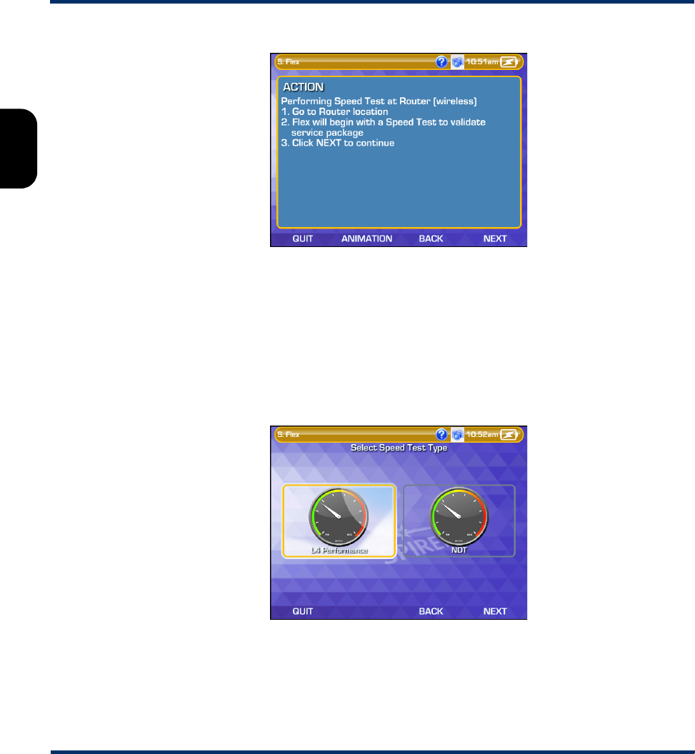
The workflow
The workflow begins with a typical instructional screen. As the first part of this workflow is WAN testing at
the router, the instructions and optional animation guide you to the router location.
Preliminary issue - Limited distribution only!
Tech-X Flex User Guide - Firmware v06.50 Tech-X Flex® (NG2)
2-4
Intro Overview Wi-Fi Ethernet System IP/Video MoCA RF Specs
Figure 2-3 Wi-Fi INSTALLATION workflow - Router testing instructional screen
At the bottom of this screen, you can see the common navigational tools for workflows, including QUIT,
ANIMATION, BACK, and NEXT. These controls are the most intuitive method of navigation, although
some screens provide alternative methods such as buttons and mouse click responses. Any provided
method is acceptable.
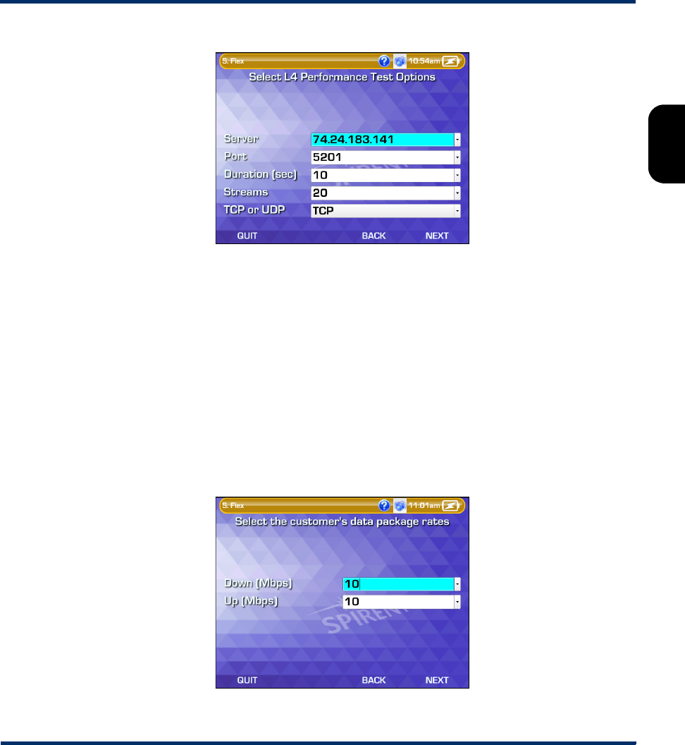
The first testing action of the workflow is a speed test, for which you have the option of a L4
Performance Test or an NDT-based Speed Test. So, the next screen of the workflow requires this
selection:
Figure 2-4 Wi-Fi INSTALLATION workflow - Speed test type selection
After you select the test type, you must enter the applicable setup parameters. For this example, the L4
Performance Test was selected.
Preliminary issue - Limited distribution only!
Tech-X Flex® (NG2) Tech-X Flex User Guide - Firmware v06.50
2-5
Intro
Overview
Wi-Fi
Ethernet
System
IP/Video
MoCA
RF
Specs
Figure 2-5 Wi-Fi INSTALLATION workflow - Speed test setup
At this point, for detailed information on the test setup, you must refer to the applicable part of this
document that describes the underlying test. The tables under Overview of existing workflows on
page 2-8 provide applicable links for all supported workflows. For this workflow specifically, see one of:
•L4 Performance Test on page 6-7
•Speedtest on page 6-17
NOTE: In most circumstances, it is likely that the proper setup parameters are pre-determined by
administrators and/or other subject-matter experts, then provided to testers as some form of
common work instruction.
The workflow then requests the data rates for the customer. The workflow uses these numbers as
pass/fail thresholds for the subsequent speed testing.
Figure 2-6 Wi-Fi INSTALLATION workflow - Data rate selection
Preliminary issue - Limited distribution only!
Tech-X Flex User Guide - Firmware v06.50 Tech-X Flex® (NG2)
2-6
Intro Overview Wi-Fi Ethernet System IP/Video MoCA RF Specs
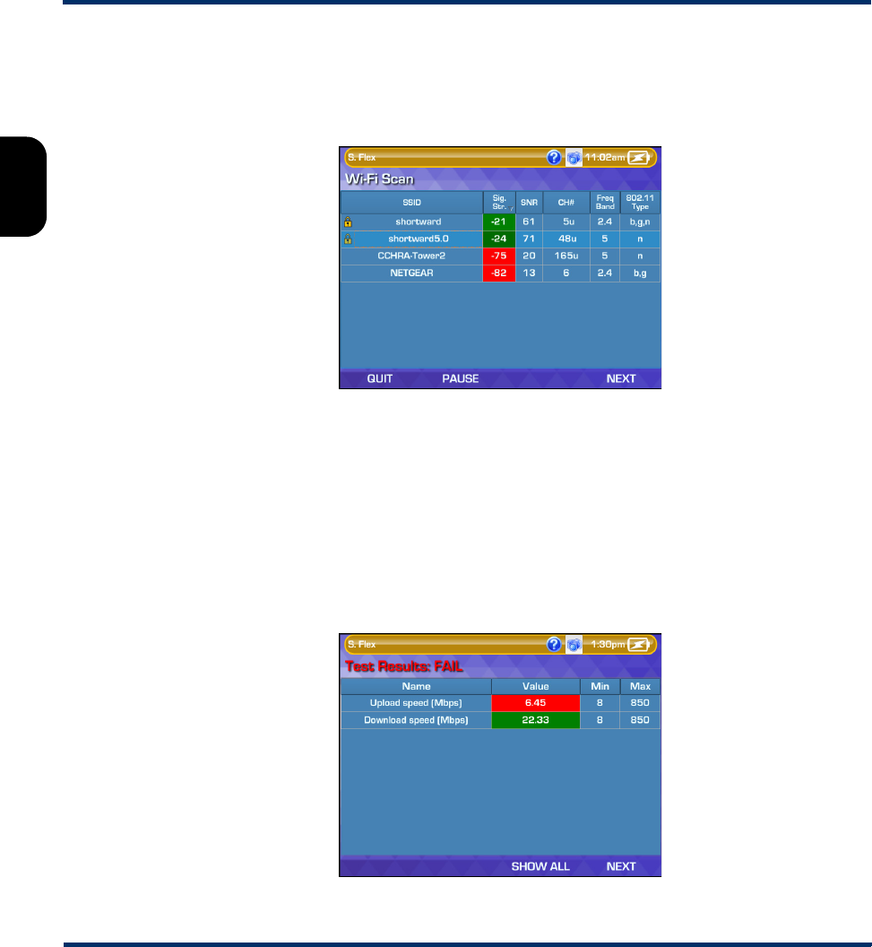
Noting that a Wi-Fi connection has yet to be established, the workflow begins the connection setup. The
first screen is a modification of the classic Wi-Fi Scan, where you can select the proper customer
network. After this screen, the workflow requests the authentication parameters, similar to the classic Wi-
Fi Connect function (see Wi-Fi Setup > Connect on page 3-7).
Figure 2-7 Wi-Fi INSTALLATION workflow - Wi-Fi scan results
Once the connection parameters are submitted, the workflow enters a state of automatic processing
where it attempts to connect to the selected network, obtain an IP address, run the speed testing, and
compare the results with the specified thresholds. At any point, if the process cannot complete, the
workflow provides a warning and begins to exit.
If the testing completes without issue, the workflow presents the results. If the data rates do not meet the
thresholds, the workflow initiates a wired Ethernet speed test to determine whether the issue is
associated with the Wi-Fi connection or the upstream WAN. At this point, if either test reveals issues, you
might decide to terminate the workflow and troubleshoot accordingly.
Figure 2-8 Wi-Fi INSTALLATION workflow - WAN speed testing results
Preliminary issue - Limited distribution only!
Tech-X Flex® (NG2) Tech-X Flex User Guide - Firmware v06.50
2-7
Intro
Overview
Wi-Fi
Ethernet
System
IP/Video
MoCA
RF
Specs
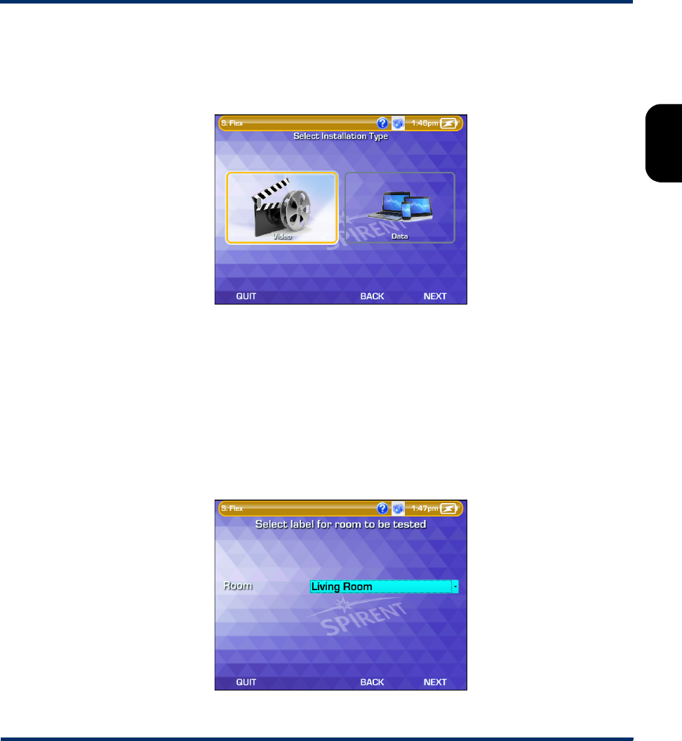
Assuming that WAN throughput is acceptable and you are ready to continue, the workflow moves to its
second major stage, LAN testing. To complete the workflow, independent testing must be run at the
location of each Wi-Fi client (STB, computer, etc.), or any other location where you want to verify the
service. Before this testing proceeds, the workflow requests the selection of either Video or Data:
Figure 2-9 Wi-Fi INSTALLATION workflow - Installation type selection
The primary difference between these options is the pass/fail thresholds applied to the results. The
testing procedure is the same for both, where you should:
1. Move the unit to an appropriate testing location; that is, a place where Wi-Fi performance is
important.
2. In the workflow setup, specify a “name” (Room) for the location, which serves as an identifier within
the results only.
3. Initiate the testing and wait for it to finish.
4. Repeat this procedure for all desired testing locations.
Figure 2-10 Wi-Fi INSTALLATION workflow - Room label selection
Preliminary issue - Limited distribution only!

Tech-X Flex User Guide - Firmware v06.50 Tech-X Flex® (NG2)
2-8
Intro Overview Wi-Fi Ethernet System IP/Video MoCA RF Specs
Once you have completed all the rooms, you can navigate to the completion of the workflow. The
workflow will present some recommendations based on the results of testing, then allow you to view the
complete set of results for each location.
NOTE: Where applicable, pass/fail evaluations are presented based on scripted thresholds. Likely,
these thresholds will be customized for any specific deployment, based on site-specific
requirements.
Figure 2-11 Wi-Fi INSTALLATION workflow - Final results
Once the workflow exits, you are complete. Like all workflows, the results are saved automatically in the
Record Manager for future upload.
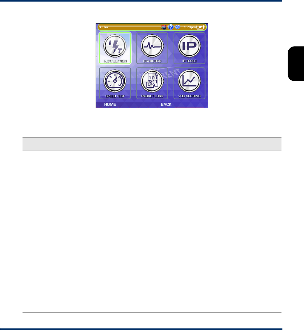
2.1.3 Overview of existing workflows
The following information briefly describes the default workflows provided with the unit, organized by top-
level functional area.
Preliminary issue - Limited distribution only!
Tech-X Flex® (NG2) Tech-X Flex User Guide - Firmware v06.50
2-9
Intro
Overview
Wi-Fi
Ethernet
System
IP/Video
MoCA
RF
Specs
Figure 2-12 MoCA-RF > MoCA workflow menu
Table 2-1 MoCA workflow descriptions
Workflow Description/notes For more information
INSTALLATION Synchronizes with a MoCA network,
then runs a MoCA Quick Test.
Pass/fail criteria is applied based on
normal thresholds configured for
MoCA testing.
• On the input parameters required for the
synchronization, see Join MoCA
network setup parameters on page 7-5.
• On the input parameters, thresholds,
and results related to the MoCA Quick
Test, see MoCA Quick Test on
page 7-23.
STATISTICS Synchronizes with a MoCA network
and produces comprehensive MoCA
statistics. It does not set up an IP
interface.
• On the input parameters required for the
synchronization, see Join MoCA
network setup parameters on page 7-5.
• On the results that display on standard
classic screens, see MoCA Network
Statistics on page 7-9.
IP TOOLS Synchronizes with a MoCA network
and sets up an IP interface using
DHCP. Then, it guides the user
through Ping, Traceroute, and/or
Web Browser testing, where the user
must provide standard input
parameters related to test
destinations.
• On the input parameters required for the
synchronization, see Join MoCA
network setup parameters on page 7-5.
•On Ping testing, see Ping on page 6-4.
•On Traceroute testing, see Traceroute
on page 6-6.
•On Web Browser testing, see Web
Browser on page 6-10.
Preliminary issue - Limited distribution only!

Tech-X Flex User Guide - Firmware v06.50 Tech-X Flex® (NG2)
2-10
Intro Overview Wi-Fi Ethernet System IP/Video MoCA RF Specs
SPEED TEST Synchronizes with a MoCA network
and then runs either a L4
Performance Test or an NDT-based
Speed Test. Standard input
parameters for the speed testing
apply.
• On the input parameters required for the
synchronization, see Join MoCA
network setup parameters on page 7-5.
• On the input and result parameters for
the L4 Performance Test, see L4
Performance Test on page 6-7.
• On the input and result parameters for
the Speed Test, see Speedtest on
page 6-17.
PACKET LOSS Synchronizes with a MoCA network
and then guides the user through a
Packet Loss Test. Standard test input
parameters apply.
• On the input parameters required for the
synchronization, see Join MoCA
network setup parameters on page 7-5.
•On Packet Loss Test testing, see
Single Device PLT on page 6-11.
VOD SCORING Synchronizes “inline” with a MoCA
network and then runs a Video QoS
test. This workflow requires several
setup steps, including the connection
of the unit inline with the network, the
physical initiation of a VoD stream on
the network and the entry of several
complex setup parameters. The setup
and results of the Video QoS test use
classic view screens.
• On the input parameters required for the
synchronization, see Join MoCA
Network In-Line (Bridging and passive
testing) on page 7-19.
• On the setup and results of the Video
QoS test, see Video QoS (Quality of
Service) on page 6-23.
Workflow Description/notes For more information
Preliminary issue - Limited distribution only!
Tech-X Flex® (NG2) Tech-X Flex User Guide - Firmware v06.50
2-11
Intro
Overview
Wi-Fi
Ethernet
System
IP/Video
MoCA
RF
Specs
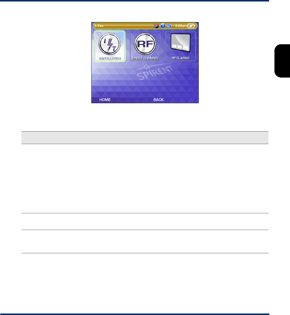
Figure 2-13 MoCA-RF > RF workflow menu
Table 2-2 RF workflow descriptions
Workflow Description/notes For more information
INSTALLATION Runs a Channel Sweep Test on a
series of specified channels. Like the
same test launched from the classic
view, the workflow version requires
you to select a test location, which
determines the set of thresholds to
apply. All setup and results use
customized workflow screens, but
have the same meaning as their
classic view equivalents.
On the setup and results of the Channel
Sweep Test, see Channel Sweep Test on
page 8-2.
SINGLE
CHANNEL
Launches the classic view of the
Single Channel Test.
See Single Channel Test on page 8-4.
RF CLASSIC Switches to the classic RF menu. This
action closes the workflow view
completely.
See MoCA/RF - RF Testing on page 8-1.
Preliminary issue - Limited distribution only!
Tech-X Flex User Guide - Firmware v06.50 Tech-X Flex® (NG2)
2-12
Intro Overview Wi-Fi Ethernet System IP/Video MoCA RF Specs
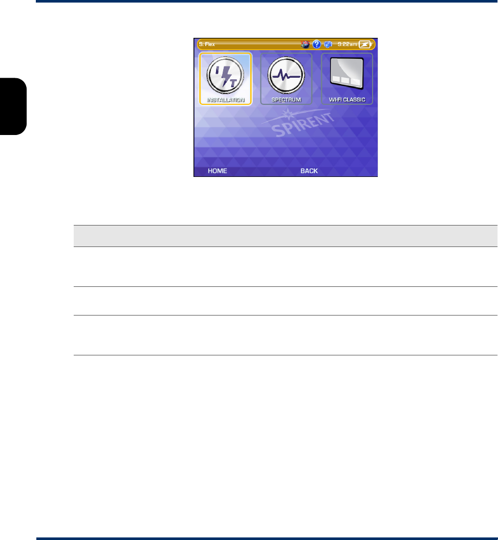
Figure 2-14 Wi-Fi workflow menu
Table 2-3 Wi-Fi workflow descriptions
Workflow Description/notes For more information
INSTALLATION Runs a series of tests to verify a
complete service installation with a
Wi-Fi router.
See Workflow usage example (Wi-Fi
INSTALLATION) on page 2-3.
SPECTRUM Launches the classic view of the Wi-Fi
Spectrum Analysis.
See Wi-Fi Spectrum Analysis on
page 3-17.
WI-FI CLASSIC Switches to the classic Wi-Fi menu.
This action closes the workflow view
completely.
See Wi-Fi Testing Menu on page 3-1.
Preliminary issue - Limited distribution only!
Tech-X Flex® (NG2) Tech-X Flex User Guide - Firmware v06.50
2-13
Intro
Overview
Wi-Fi
Ethernet
System
IP/Video
MoCA
RF
Specs
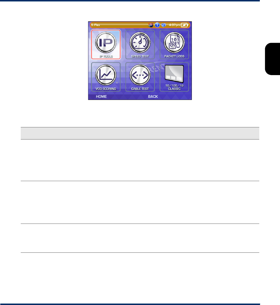
Figure 2-15 ETHERNET workflow menu
Table 2-4 ETHERNET workflow descriptions
Workflow Description/notes For more information
IP TOOLS Establishes an IP interface using
DHCP, then guides the user through
Ping, Traceroute, and/or Web
Browser testing, where the user must
provide standard input parameters
related to test destinations.
•On Ping testing, see Ping on page 6-4.
•On Traceroute testing, see Traceroute
on page 6-6.
•On Web Browser testing, see Web
Browser on page 6-10.
SPEED TEST Establishes an IP interface using
DHCP, then runs either a L4
Performance Test or an NDT-based
Speed Test. Standard input
parameters for the speed testing
apply.
• On the input and result parameters for
the L4 Performance Test, see L4
Performance Test on page 6-7.
• On the input and result parameters for
the Speed Test, see Speedtest on
page 6-17.
PACKET LOSS Establishes an IP interface using
DHCP, then guides the user through a
Packet Loss Test. Standard test input
parameters apply.
See Single Device PLT on page 6-11.
Preliminary issue - Limited distribution only!

Tech-X Flex User Guide - Firmware v06.50 Tech-X Flex® (NG2)
2-14
Intro Overview Wi-Fi Ethernet System IP/Video MoCA RF Specs
VOD SCORING Establishes an IP interface using
DHCP, then runs a Video QoS test.
This workflow requires several setup
steps, including the physical initiation
of a VoD stream on the network and
the entry of several complex setup
parameters. The setup and results of
the Video QoS test use classic view
screens.
See Video QoS (Quality of Service) on
page 6-23.
CABLE TEST Initiates an Ethernet Cable Test, with
no user input required. Assuming a
connection with an active Ethernet
signal, the following conditions cause
a failed condition:
• The link status is not 1 Gbps full
duplex -or- if auto-negotiation fails.
• The link is not 1 Gbps link due to
one or more open pairs.
• Pair polarity or straight-through
mapping is incorrect.
• Any skew value is greater than 16
ns.
See Ethernet Cable Test on page 4-6.
WI-FI CLASSIC Switches to the classic 10/100/1G
menu. This action closes the workflow
view completely.
See 10/100/1G Testing Menu on page 4-1.
Workflow Description/notes For more information
Preliminary issue - Limited distribution only!
Tech-X Flex® (NG2) Tech-X Flex User Guide - Firmware v06.50
2-15
Intro
Overview
Wi-Fi
Ethernet
System
IP/Video
MoCA
RF
Specs
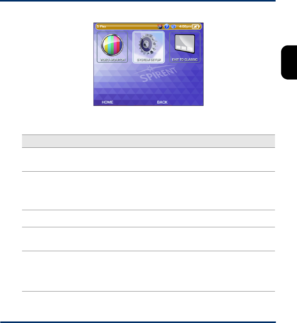
Figure 2-16 SYSTEM workflow menu
Table 2-5 SYSTEM workflow descriptions
Workflow Description/notes For more information
VIDEO MONITOR Launches the Video Monitor feature.
The normal dongle and associated
setup is required.
See Video > Video Monitor on page 5-11.
SYSTEM SETUP >
INITIAL SETUP
Guides the user through some basic
unit setup, as a shortcut to areas
available in the classic System menu.
This setup includes base unit and
date/time settings.
• On general unit settings, see
System/Module Settings > Base Unit on
page 5-16.
• On the date/time setup, see Set Date
and Time on page 5-6.
SYSTEM SETUP >
VERSION INFO
Launches the classic Version Info
screen.
See Version Info on page 5-7.
SYSTEM SETUP >
UPGRADE
FIRMWARE
Guides the user through a firmware
upgrade process using either the
10/100/1G or Wi-Fi interface.
See Update Firmware on page 5-13.
SYSTEM SETUP >
REMOTE
CONTROL
Guides the user through a “remote
control” setup, using either the “local
access point” or VNC-over-WAN
approach.
See:
•Local remote control (via a Wi-Fi access
point) setup on page 2-45
•Remote site remote control (via the
internet) setup on page 2-46
Preliminary issue - Limited distribution only!

Tech-X Flex User Guide - Firmware v06.50 Tech-X Flex® (NG2)
2-16
Intro Overview Wi-Fi Ethernet System IP/Video MoCA RF Specs
2.2 Product overview
The following sections provide a high-level overview of the unit.
2.2.1 Base unit features
NOTE: Your unit may or may not include all of the features described here, dependent upon your
licensing agreement with Spirent. Please contact Spirent for more information.
•Ethernet and IP connectivity testing - With its 10/100/1G interface, the unit can link to an Ethernet
network at any standard transport device such as a home router, hub, or Ethernet switch. Once
linked, the unit can join an IP network and perform testing such as ping, traceroute, and internet
webpage access. These abilities make the unit ideal for verifying connectivity within the home and
isolating problems to either the provider or subscriber networks.
•Wi-Fi testing - The unit includes a Wi-Fi interface that can sync with wireless devices using standard
802.11 protocols such as b, g, n, and ac, including support for WEP and WPA security. Similar to
Ethernet testing, the Wi-Fi interface allows you to join a wireless network and perform IP-based
testing to verify connectivity and sectionalize issues.
•IP video analysis - The unit is able to join a video stream and measure video quality and channel
change time. In this fashion, it can emulate a set-top box (STB) and provide a comprehensive
evaluation of IPTV quality. It can also bridge an existing stream on a link for passive monitoring. For
example, it can be placed between a home router and a real STB to passively monitor the video
communications between the devices, even while the video is simultaneously displaying on a TV.
•Expansion of features with modular hardware - The unit is designed for expansion by attaching
feature-specific modules, such as the MoCA/RF module for testing of home MoCA networks. For
more information on available modules, please contact Spirent. For more information on the
operation of any specific module, see the documentation for that module.
EXIT TO CLASSIC Switches to the classic SYSTEM
menu. This action closes the workflow
view completely.
See System Menu on page 5-1.
Workflow Description/notes For more information
Preliminary issue - Limited distribution only!
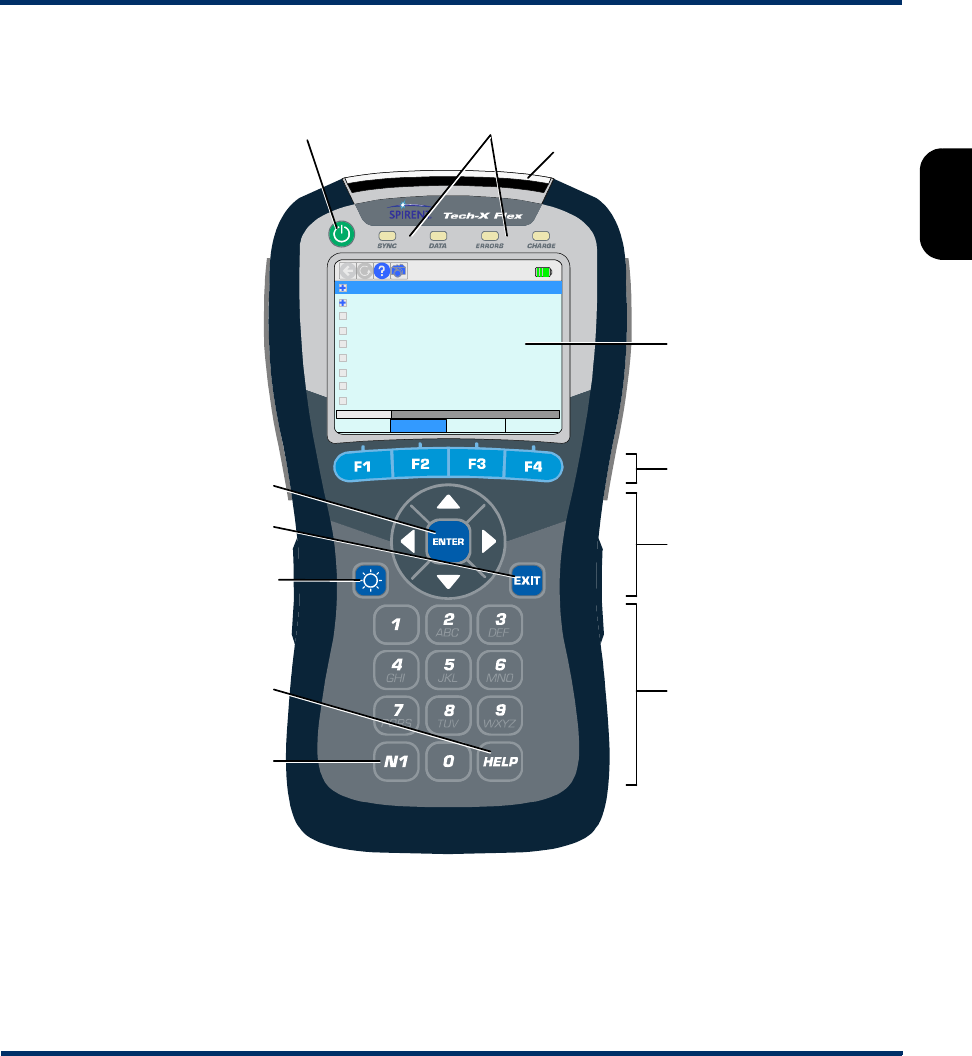
Tech-X Flex® (NG2) Tech-X Flex User Guide - Firmware v06.50
2-17
Intro
Overview
Wi-Fi
Ethernet
System
IP/Video
MoCA
RF
Specs
2.2.2 Front panel controls
Figure 2-17 Front panel controls
6: Web Browser
2: IP Network Setup
3: Connection Info
4: Ping
5: Traceroute
0: Wi-Fi Setup – 802.11bgn
MoCA-RF Wi-Fi 10/100/1G System
[Wi-Fi]
7: Packet Loss Test
8: Throughput
1: Wi-Fi Setup – 802.11ac
Touchscreen
display
Power on/off LED indicators
Function keys
Alphanumeric
keypad
(physical)
Enter
Exit
Brightness
Help
N1
Strap mount
Arrow keys
Preliminary issue - Limited distribution only!

Tech-X Flex User Guide - Firmware v06.50 Tech-X Flex® (NG2)
2-18
Intro Overview Wi-Fi Ethernet System IP/Video MoCA RF Specs
Table 2-6 Front panel feature descriptions
2.2.3 LED indicators
Indicator Function
Power on/off Powers the unit on and off, and is also used to place the unit into sleep mode (see
Powering on/off on page 2-22).
LED indicators See LED indicators on page 2-18.
Strap mount See Attaching the strap on page 2-22.
Enter Engages the active control on the screen, such as a button or a text entry box.
Exit Halts the current action or test, often returning the display to the previous screen.
Brightness Adjusts the brightness of the display. Also, this button can be used to take a screen
capture (see Capturing a screen image (screenshot) on page 2-28).
Help Used as a backspace on the text entry pad. Some screens also allow access to the
online help documentation with this button.
N1 Used for miscellaneous, specialized functions. For example, it is used to enter
special characters on the standard keypad, such as periods. For more information,
see Running a function or test on page 2-24.
Function keys Used to select the active test interface and/or functional area, such as the Wi-Fi
interface or the System configuration menu.
Arrow keys Provide navigational control over numerous display items, such as scroll bars,
multi-item lists, parameter entry screen controls, tabs, and more.
Alphanumeric
keypad
Used for text entry.
Preliminary issue - Limited distribution only!

Tech-X Flex® (NG2) Tech-X Flex User Guide - Firmware v06.50
2-19
Intro
Overview
Wi-Fi
Ethernet
System
IP/Video
MoCA
RF
Specs
Table 2-7 LED indicator description
Indicator Function
SYNC Indicates the status of the link over the active interface. For example, when using the Wi-
Fi interface, the LED indicates the status of the Wi-Fi link. The general behavior is as
follows:
•Solid green - The unit is properly linked and/or synchronized with a comparable far-
end device. For the 10/100/1G interface, the LED is solid green any time the interface
is configured with IP information, but does not necessarily indicate that the information
is valid and routable.
•Red - The unit is attempting to configure the active interface and/or link with a far-end
device.
Note that some module interfaces use the SYNC LED differently. For module-specific
LED behavior, see the respective module documentation.
DATA Flashes when sending or receiving data over the active interface. For example, when
using the 10/100/1G interface, the LED flashes when an Ethernet frame is sent or
received.
ERRORS Indicates errors at the data link level on the active data stream. For example, on the
10/100/1G interface, the LED may indicate Ethernet frame CRC errors.
CHARGE Indicates power source and charging status, as follows:
•Solid red - Unit is connected to an external power source and the battery is charging
•Solid green - Unit is connected to an external power source and the battery is nearly
or fully charged
•Off - Unit is not connect to external power (unit on or off) and/or the unit has no battery
installed
Note that the unit includes a system feature for reporting detailed information about
battery status. For more information, see Battery Status on page 5-8.
Preliminary issue - Limited distribution only!
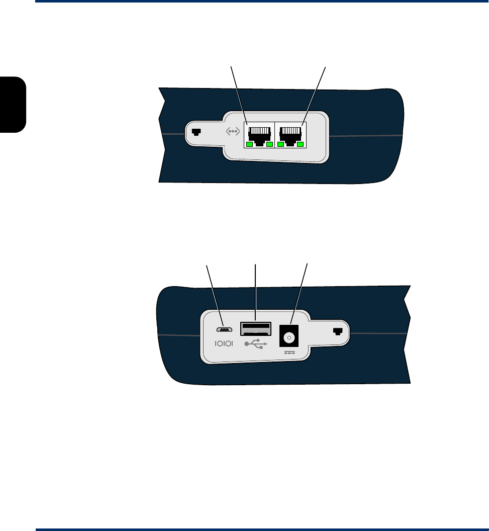
Tech-X Flex User Guide - Firmware v06.50 Tech-X Flex® (NG2)
2-20
Intro Overview Wi-Fi Ethernet System IP/Video MoCA RF Specs
2.2.4 Base unit physical interfaces (ports)
Figure 2-18 Base unit right side
Figure 2-19 Base unit left side
Note the following:
• Modules have their own physical interfaces. See the documentation for the respective module for
more information.
• The two Ethernet interfaces are used for 10/100/1G testing and for administrative functions on the
unit, such as upgrading firmware. LED behavior is as follows:
Ethernet (10/100/1G) port 1
1-2
Ethernet (10/100/1G) port 2
Special use only
Do not connect
unless specifically
instructed!
12V
External power/
charge
Standard
USB port
2A
Preliminary issue - Limited distribution only!
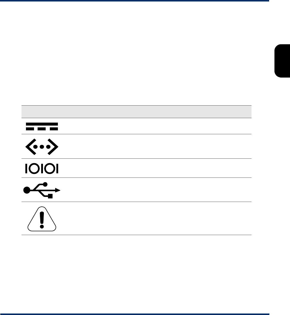
Tech-X Flex® (NG2) Tech-X Flex User Guide - Firmware v06.50
2-21
Intro
Overview
Wi-Fi
Ethernet
System
IP/Video
MoCA
RF
Specs
– When connected to a 10/100 network, the LED towards the bottom of the base unit will illuminate
green and flash when there is data activity
– When connected to a 1G network, the LED towards the top of the base unit will illuminate green
and flash when there is data activity
• The USB port is used for specialized functions related to transferring files to and from the unit. This
port and related functions are described elsewhere in the product documentation as applicable.
2.2.5 Unit symbols
The following table describes symbols that may appear on the physical body of the unit.
Table 2-8 Unit symbols
2.3 General product handling and operation
This section provides basic information for general operation. For most functions and tests, the buttons,
display, and other components operate in a similar fashion. Once you become familiar with general
operation, you should be able to set up and run most functions and tests, referring to this document only
as necessary for specific technical details, contained elsewhere in this document.
Symbol Description
DC power input.
Ethernet port.
Port for special use only. Do not plug anything into this port unless
specifically instructed by Spirent. Improper use could damage the unit.
USB port.
A symbol which may appear on the unit indicating that this documentation
should be reviewed thoroughly before using the product.
Preliminary issue - Limited distribution only!

Tech-X Flex User Guide - Firmware v06.50 Tech-X Flex® (NG2)
2-22
Intro Overview Wi-Fi Ethernet System IP/Video MoCA RF Specs
2.3.1 Protection from water and dust ingress
Although the basic unit provides some protection from water and dust ingress for outdoor use, Spirent
recommends the use of the optional jacket to increase the level of protection. For information about
purchasing the jacket, please contact your account representative.
2.3.2 Important battery charging note
The battery will not charge if its internal temperature is 113° F. (45° C.) or higher. However, upon
connection to external power, the unit may still report that it is charging in the system status and/or the
CHARGE LED may illuminate green. The following paragraphs describe this behavior in more detail.
The Li-Ion battery used in the unit is a “smart” battery that communicates important metrics to the unit
CPU. Included in these metrics is the desired charge current. When the battery exceeds the temperature
limit, it indicates that no charge current is desired, which the unit interprets as fully-charged. Because the
battery does not report the overtemperature condition, the unit must default to indicating a fully-charged
state.
Because of this temperature limit, use caution when leaving the unit in direct sunlight or any other warm
environment. For example, a unit resting on a dashboard in direct sunlight can heat to very high
temperatures in a very short amount of time. If a battery heats up beyond the temperature limit, simply
allow it to cool and charging will resume normally when the temperature reaches an acceptable level.
Note that the battery status screen accurately reports the current battery temperature, whether or not
charging is enabled. For more information, see Battery Status on page 5-8.
2.3.3 Powering on/off
When the unit is off, the power button turns it on. When the unit is on, the power button prompts you
whether to power off the unit.
While on battery power, the unit supports automatic shutdown after a specified amount of idle time. For
more information, see System/Module Settings > Base Unit on page 5-16.
2.3.4 Attaching the strap
A strap with a hook is provided to hang the unit while working. To attach the strap, first make sure that the
buckle is facing up, then slide the open end around and through the strap mount at the top of the unit:
Preliminary issue - Limited distribution only!
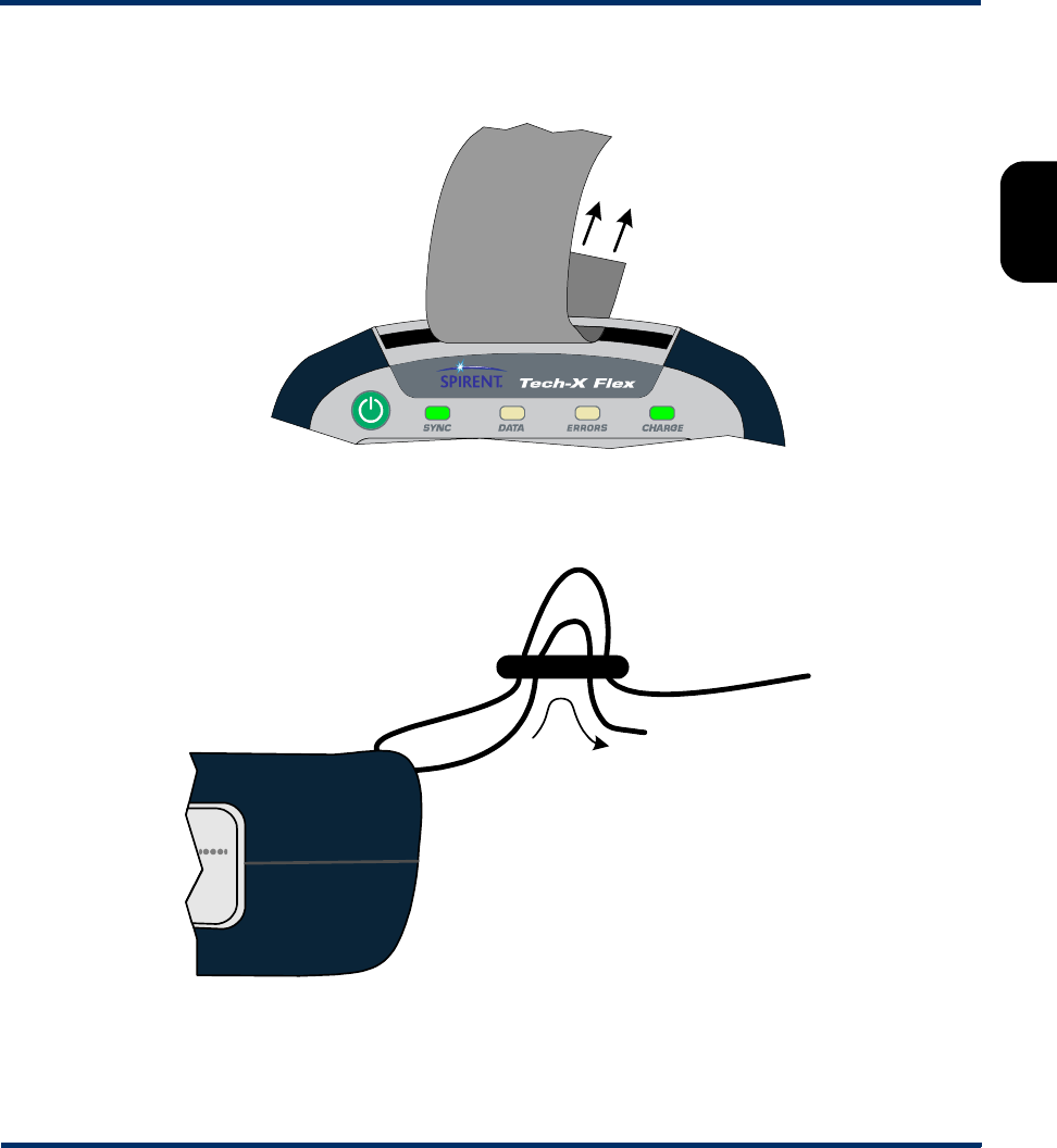
Tech-X Flex® (NG2) Tech-X Flex User Guide - Firmware v06.50
2-23
Intro
Overview
Wi-Fi
Ethernet
System
IP/Video
MoCA
RF
Specs
Figure 2-20 Sliding the open strap end through the strap mount
Next, feed the open end through the bottom of the buckle as shown in the following figure:
Figure 2-21 Feeding the strap through the buckle
(To hook)
Strap end
2
Strap end
(To hook)
Buckle
Preliminary issue - Limited distribution only!

Tech-X Flex User Guide - Firmware v06.50 Tech-X Flex® (NG2)
2-24
Intro Overview Wi-Fi Ethernet System IP/Video MoCA RF Specs
2.3.5 About the touchscreen display
The unit display includes touchscreen functionality which allows you to operate most display controls by
touching the screen. You should use the provided stylus or a similar device. It is recommended to avoid
using your fingers because it is difficult to control selections with precision.
CAUTION: Never use a sharp or metallic object, pen, pencil, or other such instrument
which will mar the screen.
For new units, units with new firmware, or units with a new battery, a calibration of the touchscreen
should be performed. For more information, see Cal Touchscreen on page 5-12.
2.3.6 Selecting the active interface
While testing with the unit, the first step is to select the appropriate interface with one of the function
keys, such as the 10/100/1G or Wi-Fi interface, or perhaps another interface associated with an attached
module. The interface and any associated hardware remain active only while testing in the respective
area continues. If you switch to a different interface, the previous interface shuts down and loses its IP
configuration, if any. For example, if you switch from the Wi-Fi interface to the 10/100/1G interface, the
Wi-Fi interface will shut down and any IP configuration will be lost.
An exception exists with the Wi-Fi interface, which can be optionally configured to remain active all the
time. For more information, see System/Module Settings > Base Unit on page 5-16.
2.3.7 Running a function or test
To run any function or test, the following steps generally apply:
Preliminary issue - Limited distribution only!
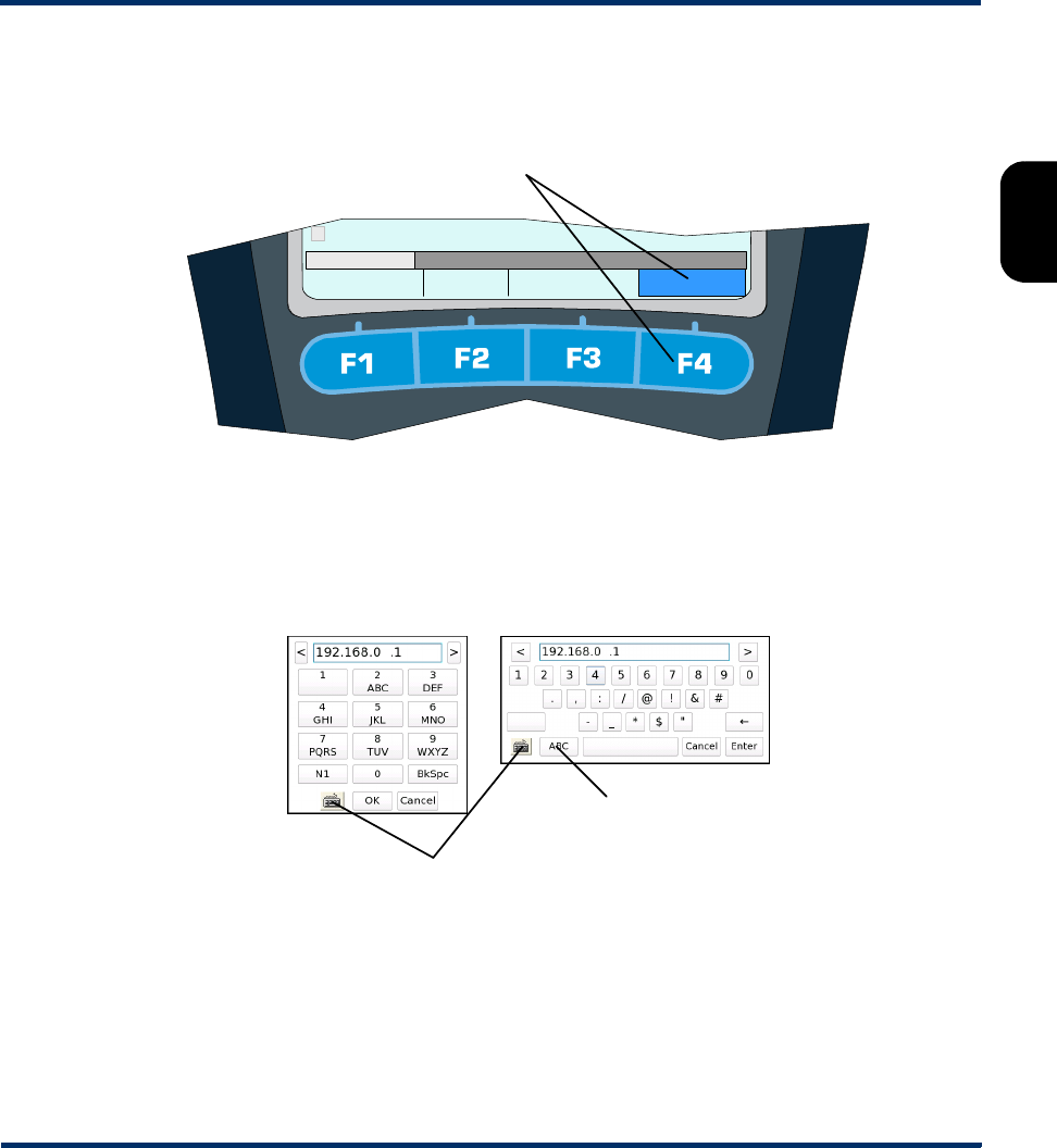
Tech-X Flex® (NG2) Tech-X Flex User Guide - Firmware v06.50
2-25
Intro
Overview
Wi-Fi
Ethernet
System
IP/Video
MoCA
RF
Specs
1. Using the function keys or the touchscreen, select the correct menu/interface.
2. Using the up/down arrows, number pad, and/or touchscreen, select the desired menu item and
possibly submenu items to activate the desired function/test.
3. For tests that require input parameters, adjust those parameters as necessary, using the navigation
arrows and/or touchscreen. For free-form text entries, place the cursor in the field and press any
number key (or “double-tap” the field on the touchscreen) to produce the text entry keypad.
Using the onscreen keypad and/or the physical number keys, enter the desired data. Note the
following:
• The standard keypad is similar to a standard text message device, where you must press a key
multiple times to cycle through the associated letters. For example, to enter a “b”, press the “2”
key three times quickly, then pause.
• On the standard keypad, the N1 key allows you to enter special characters, such as a parenthesis
or angle bracket. On the QWERTY keypad, special characters are entered with the “numeric”
A function key selects the
function/test/menu directly above
Wi-Fi 10/100/1G System
8: Throughput
MoCA-RF
Standard keypad
Toggle keypad type
“QWERTY” keypad
Toggle between
numeric and alphabetic
Preliminary issue - Limited distribution only!
Tech-X Flex User Guide - Firmware v06.50 Tech-X Flex® (NG2)
2-26
Intro Overview Wi-Fi Ethernet System IP/Video MoCA RF Specs
screen and the N1 key has no effect. In all cases, the unit will disallow the entry of an invalid
character, such as illegal characters when entering a file name.
• If you enter a value that is out of range for the underlying entry field, the Enter key on the screen
becomes disabled (grayed out). For example, if the underlying field requires a value from 1-99
and you type “100” into the keypad, the Enter key will become disabled when you type the
second “0”.
• In the System menu, you can set the default keypad type that appears when you initiate text entry
(see System/Module Settings > Base Unit on page 5-16).
•The Help button on the physical keypad acts as a backspace.
4. Press the appropriate button to start the respective action, normally Start or OK.”
NOTE: The unit is designed to be controlled by either the keypad or the touchscreen, or a combination
of both. You should become familiar with both methods of unit control, because you may find
that a combination of the two provides the most efficiency.
2.3.8 Repeating a function or test
See the “retest” button under Screen title bar buttons/icons on page 2-26.
2.3.9 Screen title bar buttons/icons
The following table describes the buttons and icons that may appear in the title bar of menu and testing
screens:
Table 2-9 Title bar buttons
Image Name Description
Back Returns to the previous screen or the most logical previous menu. In many
cases, this button has the same effect as the Back button on the physical
keypad.
Preliminary issue - Limited distribution only!
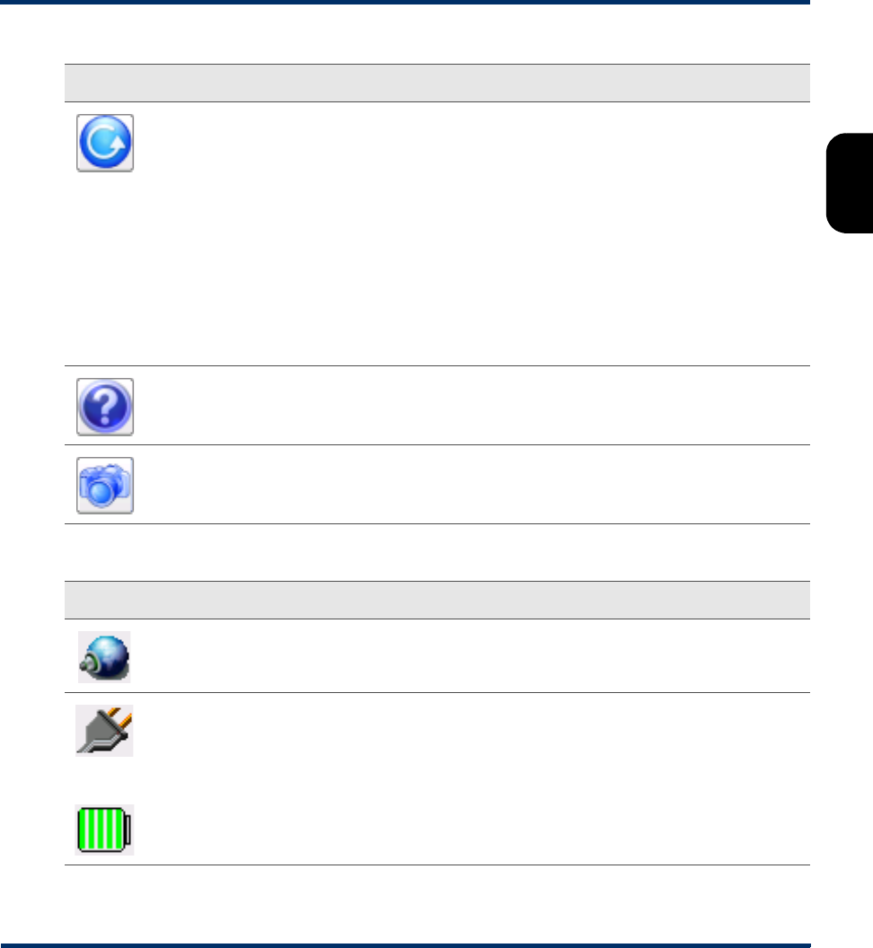
Tech-X Flex® (NG2) Tech-X Flex User Guide - Firmware v06.50
2-27
Intro
Overview
Wi-Fi
Ethernet
System
IP/Video
MoCA
RF
Specs
Table 2-10 Title bar icons
Retest Repeats (reruns) the most recent function/test, using the same setup as the
previous test. Note the following:
• This feature can also be invoked by pressing the N1 key on the physical
keypad.
• Only the most recent test can be repeated. For example, you can’t run a ping
test, then a traceroute, then repeat the ping test.
• Whenever a new test setup screen is entered, the unit automatically disables
this button.
• In any other case, if this button is disabled and the N1 key does nothing, a
retest is not feasible due to technical limitations. For example, if you run a test
with the MoCA-RF module and then switch to the 10/100/1G testing menu, the
MoCA/RF hardware will shut down and prevent a repeat of any previous test.
Help Launches the online help system, which produces an onboard viewer of this
document set.
Capture
screen
Launches a screen capture. For more information, see Capturing a screen image
(screenshot) on page 2-28.
Button Description
Indicates that an Admin Port is currently configured (see Admin Port on page 5-5).
-or-
The unit is plugged into an external power source
-or-
The unit is using battery power. For this icon, the number of green bars provides a rough
indication of remaining charge. For comprehensive details on current battery status, use
System > Battery Status (see Battery Status on page 5-8).
Image Name Description
Preliminary issue - Limited distribution only!
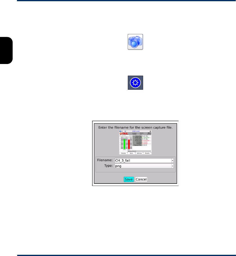
Tech-X Flex User Guide - Firmware v06.50 Tech-X Flex® (NG2)
2-28
Intro Overview Wi-Fi Ethernet System IP/Video MoCA RF Specs
2.3.10 Capturing a screen image (screenshot)
Most screens provide a screen capture feature, invoked with the screen capture button in the title bar:
Figure 2-22 Screen capture button (title bar)
...or by pressing and holding the brightness button on the physical keypad:
Figure 2-23 Brightness button (physical keypad)
Following the initial capture, the unit produces a screen that allows you to specify a filename and image
file type, after which the image is saved to the Record Manager.
Figure 2-24 Screen capture screen
Note the following:
• For more information on managing and downloading screen capture files, see Record Manager on
page 5-1.
• To capture extended drop-down lists, focus indicators, and other field-oriented artifacts, you must use
the brightness button for the capture. The title bar button will remove the focus from the current field,
collapsing any lists, etc.
Preliminary issue - Limited distribution only!

Tech-X Flex® (NG2) Tech-X Flex User Guide - Firmware v06.50
2-29
Intro
Overview
Wi-Fi
Ethernet
System
IP/Video
MoCA
RF
Specs
• When using the brightness button for the capture, the screen brightness will change momentarily,
then return to the original setting once the capture is taken.
• For most screens, the PNG (Portable Network Graphics) format provides the best compromise
between image quality and file size. The BMP (bitmap) format provides lossless quality (that is,
produces an exact replica), but uses a larger file size.
2.3.11 Stopping a test
Some tests provide a “stop” shortcut (typically F3 or F4) which may be required to stop the test. For most
other tests, the EXIT key will stop a test immediately. Also, the “back” button in the upper left corner of
the screen may sometimes be used instead of EXIT. Some tests may require a small amount of
shutdown time before terminating completely.
2.3.12 Saving results
Most tests allow you to save the results using the Save button on the results screen (F4 key). For some
long-running continuous tests, the F4 key shows the command Save Start instead, which causes results
to be saved continuously until the test is stopped or F4 is pressed again. Other continuous tests do not
allow results to be saved until the test is stopped.
When you initiate a Save action, the unit prompts you for the results file to which the results should be
written. You can either select an existing file or type a new filename to create a new file. If you select an
existing file, the unit will prompt you whether to append to or overwrite the file. If you create a new file, it
becomes part of the normal record file collection that can be managed using the Record Manager (see
Record Manager on page 5-1).
NOTE: To account for ranging, custom settings, and other factors, some tests may use different units to
display the same result. For example, a resistance measurement with the WB Copper Module
might display results in ohms, kohms, or MOhms. For consistency, however, saved results
always use the same units, with conversion from the results screen units as necessary.
2.3.13 Maximum test duration for continuous tests
For any test that can run continuously, such as a video quality of service test, the maximum duration is
four hours.
2.3.14 Interpreting results
In some cases, this document and related documents provide results samples and references to industry
standards for pass/fail criteria. None of this information should be construed as a recommendation or
Preliminary issue - Limited distribution only!

Tech-X Flex User Guide - Firmware v06.50 Tech-X Flex® (NG2)
2-30
Intro Overview Wi-Fi Ethernet System IP/Video MoCA RF Specs
mandate on how any given organization should interpret results. In all cases, you should consult local
and corporate protocol for the standards by which you interpret results. This document does not intend in
any way to serve as an authorized or approved standard for the operation and maintenance of any
telecommunications network.
2.4 Handling the MoCA/RF module
The following sections provide important information about attaching, detaching, and connecting the
optional MoCA/RF module. For comprehensive information on module functionality, see:
•MoCA/RF - MoCA Testing on page 7-1
•MoCA/RF - RF Testing on page 8-1
Note that the normal functionality of the base unit (Wi-Fi, 10/100/1G, etc.) remains unchanged while the
module is attached.
2.4.1 Attaching, detaching, and handling the module
CAUTION: Before attaching or detaching a module, the unit must be powered off or
placed into sleep mode. Failure to do this could result in damage to the module
or base unit firmware. For more information on initiating sleep mode, see
Powering on/off on page 2-22.
NOTE: To prevent damage to the module bay and to keep electrical connections clean, you should
keep the module placeholder (the “dummy” module) installed when no module is in use. New
units are shipped with the placeholder attached.
A modules is fastened to the base unit using fastener screws attached to the upper “feet” of the unit. To
remove a module, loosen/disengage the two screws and gently pull the module from its electrical
connection. Likewise, to attach a module, gently press the module into the base unit to seat the electrical
connection, then finger-tighten the screws.
Preliminary issue - Limited distribution only!
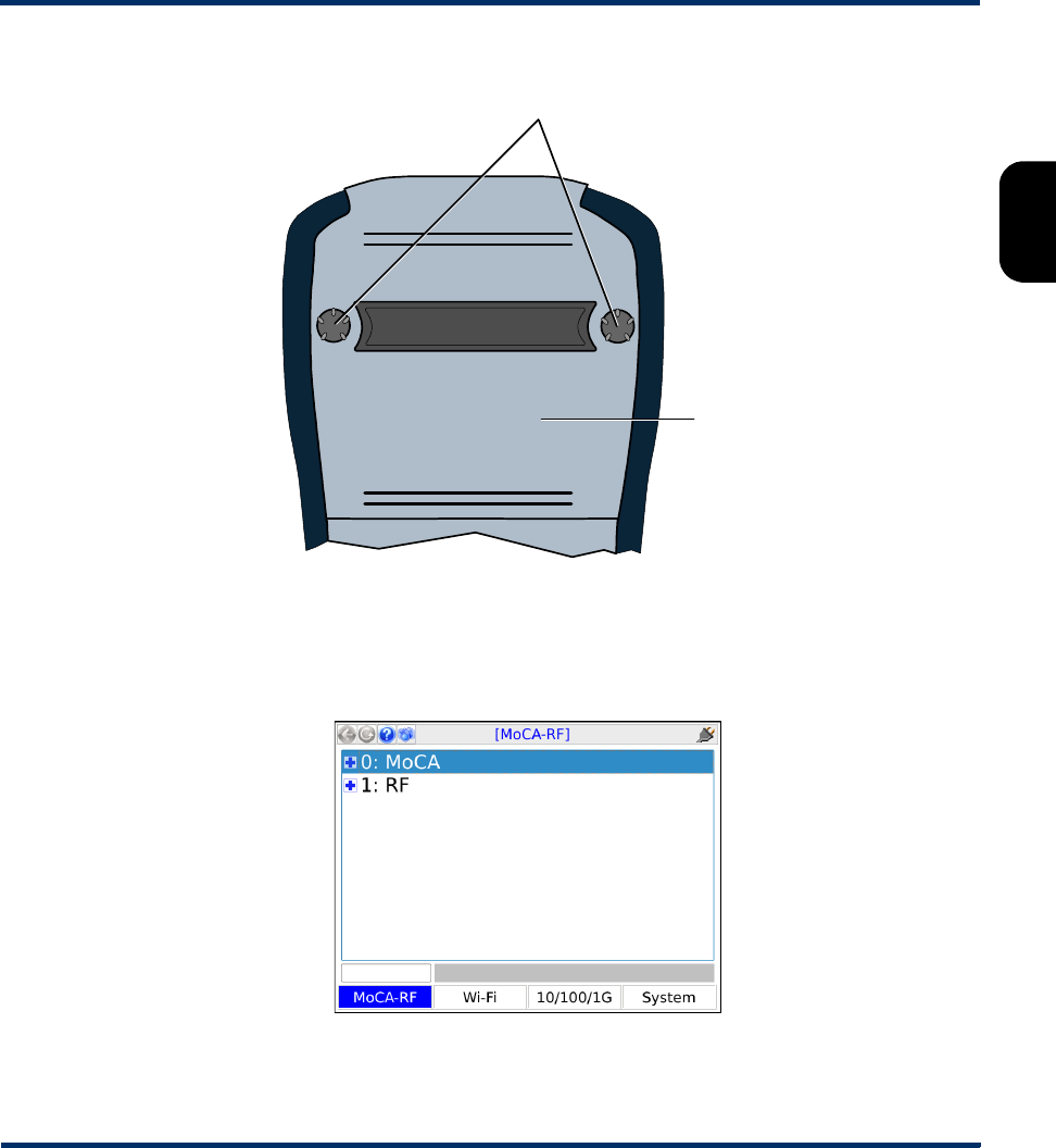
Tech-X Flex® (NG2) Tech-X Flex User Guide - Firmware v06.50
2-31
Intro
Overview
Wi-Fi
Ethernet
System
IP/Video
MoCA
RF
Specs
Figure 2-25 Rear of unit with a module installed, showing the fastener screws
Once a module is attached and has booted up, a menu corresponding to the module functionality will
appear over the F1 function key. For example, when the MoCA/RF module is attached, the F1 menu
shows MoCA-RF. If no module is attached, the F1 key shows no menu.
Figure 2-26 MoCA-RF main menu
Module
Fastener screws
Preliminary issue - Limited distribution only!

Tech-X Flex User Guide - Firmware v06.50 Tech-X Flex® (NG2)
2-32
Intro Overview Wi-Fi Ethernet System IP/Video MoCA RF Specs
2.4.2 Connecting the module to the coax network
The module has two 75 ohm F-type cable connections that can be connected to the coaxial cable
network at any suitable location. Typically, the unit is connected at a location where troubleshooting
and/or verification is specifically required, such as a set-top box (STB) or a LAN router. An adapter is
normally required for the unit connector (see How to attach/replace the coax port adapters on
page 2-32).
2.4.3 How to attach/replace the coax port adapters
Each module has two F-type coax ports which require an adapter to attach a typical coax cable
terminated by another F-type connector. Any necessary adapters are included with the module and are
intended to be replaceable, allowing them to receive the brunt of normal wear and tear rather than the
module hardware itself.
If an adapter is not attached when you receive the module, attach it according to the following diagram.
For best results, insert the “shorter” end into the module. The adapter needs to be tight enough to
prevent it from loosening when cables are removed, but it should not be overtightened. Also, note the
following:
• When tightened, the pre-fastened nut on an adapter may not be flush with the module connector. This
is OK.
• Any additional hardware supplied with an adapter, such as a nut and washer, is not used.
Figure 2-27 Attaching a coax port adapter
2.4.4 Which coaxial port to use
For all RF and single-ended MoCA testing, use the left port as viewed from the front of the unit (port A).
The other port (B) is used as the second connection for MoCA inline testing only.
Pre-fastened nut
Preliminary issue - Limited distribution only!
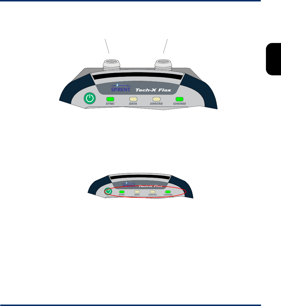
Tech-X Flex® (NG2) Tech-X Flex User Guide - Firmware v06.50
2-33
Intro
Overview
Wi-Fi
Ethernet
System
IP/Video
MoCA
RF
Specs
Figure 2-28 Coaxial port functions
2.4.5 SYNC LED behavior
The SYNC LED generally operates as follows, with respect to activities within the MoCA and RF menus:
•MoCA - Solid green when the unit is actively synchronized to a MoCA network, off otherwise.
•RF - Solid green when locked on a channel, red if a channel lock attempt failed, off otherwise.
Figure 2-29 Unit LEDs, including the SYNC LED
2.4.6 Calibration requirements
No regular calibration is required. If your local protocol dictates calibration anyway, please contact
Spirent for information on calibration options.
2.5 Remote control of the unit
With a VNC client on a PC or mobile device, you can operate the unit remotely over a network
connection, instead of using the actual touchscreen and physical keypad.
All RF testing and
single-ended MoCA testing MoCA in-line testing only
Preliminary issue - Limited distribution only!

Tech-X Flex User Guide - Firmware v06.50 Tech-X Flex® (NG2)
2-34
Intro Overview Wi-Fi Ethernet System IP/Video MoCA RF Specs
2.5.1 About VNC
VNC (Virtual Network Computing) is a technology that allows the graphical interface of one computer
(such as the display screen of the unit) to be rendered on another networked computer, where it can be
operated as if it were the original. In the case of the Tech-X Flex, VNC control means that the screen can
be displayed on a client PC or mobile device, where:
• On a PC, the unit accepts mouse clicks and keyboard entries on the VNC screen as if they were
physical touches on the touchscreen and keypad entries, respectively.
• On a mobile device, the device touchscreen assumes identical functionality to the unit touchscreen,
with respect to taps and other physical interactions.
In all cases, when the screen is manipulated on the PC or mobile device, the actual screen on the unit
responds and changes as if it were being used directly.
Many users may find important uses for VNC remote control, such as:
• A technician who needs to physically connect the unit at some place, then work at other locations
while running tests.
• A technician or manager at a remote location (perhaps a support center) who needs to see and/or
operate a unit currently in use at a subscriber site.
• Any person who might need to render the interface on another computer for training, reporting, and/or
screen capture activities.
In all cases, the PC or mobile device to be used for remote control must have a VNC client (viewer)
application installed. For more information:
• On installing a VNC viewer, see Installing a VNC client (viewer) on page 2-34.
• On VNC as a general technology, visit http://en.wikipedia.org/wiki/Virtual_Network_Computing.
2.5.2 Installing a VNC client (viewer)
From the factory, the unit firmware includes a display driver that is ready to serve the screen to a VNC
client running on another computer. Therefore, the preliminary requirement to VNC control is the
installation of that client. The following table provides some recommendations for clients tested by
Spirent:
Table 2-11 VNC client support/installation
Platform VNC client support/installation
Windows operating
system (PCs and
mobile devices)
VNC control has been tested with the following versions of RealVNC viewer:
•4.1.3 - See RealVNC 4.1.3 installation and setup on page 2-35
•5.0.5 - See RealVNC 5.0.5 installation and setup on page 2-35
Preliminary issue - Limited distribution only!

Tech-X Flex® (NG2) Tech-X Flex User Guide - Firmware v06.50
2-35
Intro
Overview
Wi-Fi
Ethernet
System
IP/Video
MoCA
RF
Specs
Note that other hardware platforms, operating systems, and/or VNC clients may also allow proper remote
control. However, is not feasible for Spirent to track and test all of them. If you would like to use a
different client, etc., you should feel free to test it and implement the solution once you are comfortable
with its reliability.
RealVNC 4.1.3 installation and setup
RealVNC 4.1.3 can be downloaded from:
http://www.filehippo.com/download_realvnc/changelog/4977
Once the EXE file is downloaded, run the file and follow the wizard prompts. Default installation settings
are adequate to establish proper functionality; however, if you have expertise with the software, you may
choose some customizations. For example, you could choose not to install the VNC server component,
as the client component is the only necessary component.
Once installed, RealVNC has a variety of options related to VNC connections, accessible from the setup
screen and from a VNC window. Normally, default settings are adequate, however the following settings
may require attention:
•Colour level (Colour & Encoding tab) - If you notice problems with performance or other display
functionality, consider trying a different setting such as Low or Full.
•Pass special keys directly to server (Inputs tab) - Normally, this setting should be unchecked for
best results. If checked, you may have trouble with operations such as using a PC PrtScn key to
capture a screenshot, because the keyboard input will be passed to the unit, not the PC.
•Rate-limit mouse move events (Inputs tab) - Normally, this setting should be checked for best
results. This setting limits the amount of hover/movement-related events sent to the unit, which are
less critical for proper operation. Without this setting, on fast networks the unit may receive more
input than necessary, causing a processing backlog and thus delays in control.
RealVNC 5.0.5 installation and setup
RealVNC 5.0.5 can be downloaded from:
http://www.realvnc.com/download/viewer/
Android operating
system (mobile
devices)
VNC control has been tested with the Mocha VNC Lite app, v2.1. The app is
free and may be downloaded from the normal app store on the device. Follow
the instructions provided during the download/installation.
Platform VNC client support/installation
Preliminary issue - Limited distribution only!
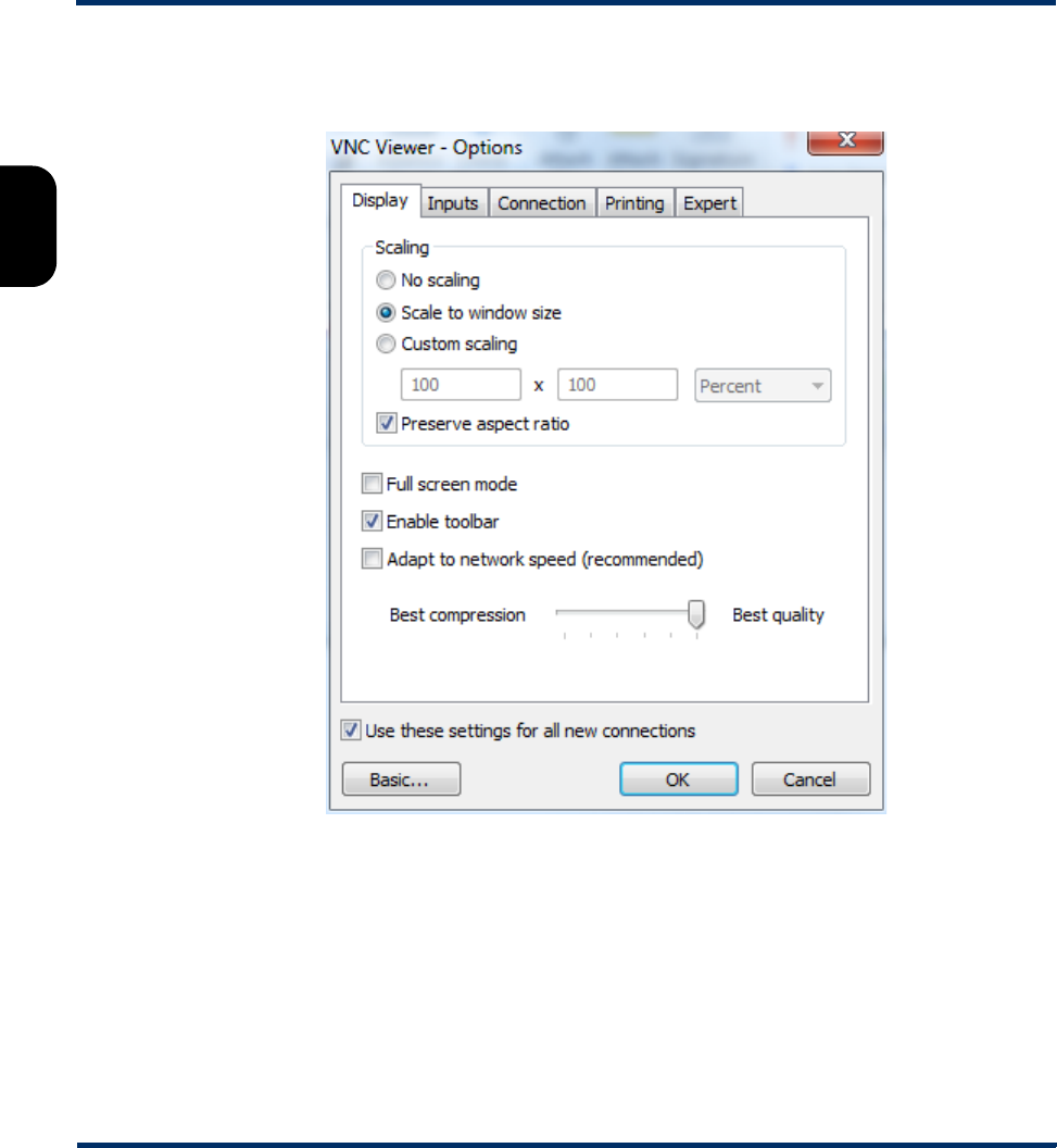
Tech-X Flex User Guide - Firmware v06.50 Tech-X Flex® (NG2)
2-36
Intro Overview Wi-Fi Ethernet System IP/Video MoCA RF Specs
Once installed, the Advanced options (accessible with the Options button) must be configured as
follows:
Figure 2-30 Advanced options - Display tab
Preliminary issue - Limited distribution only!
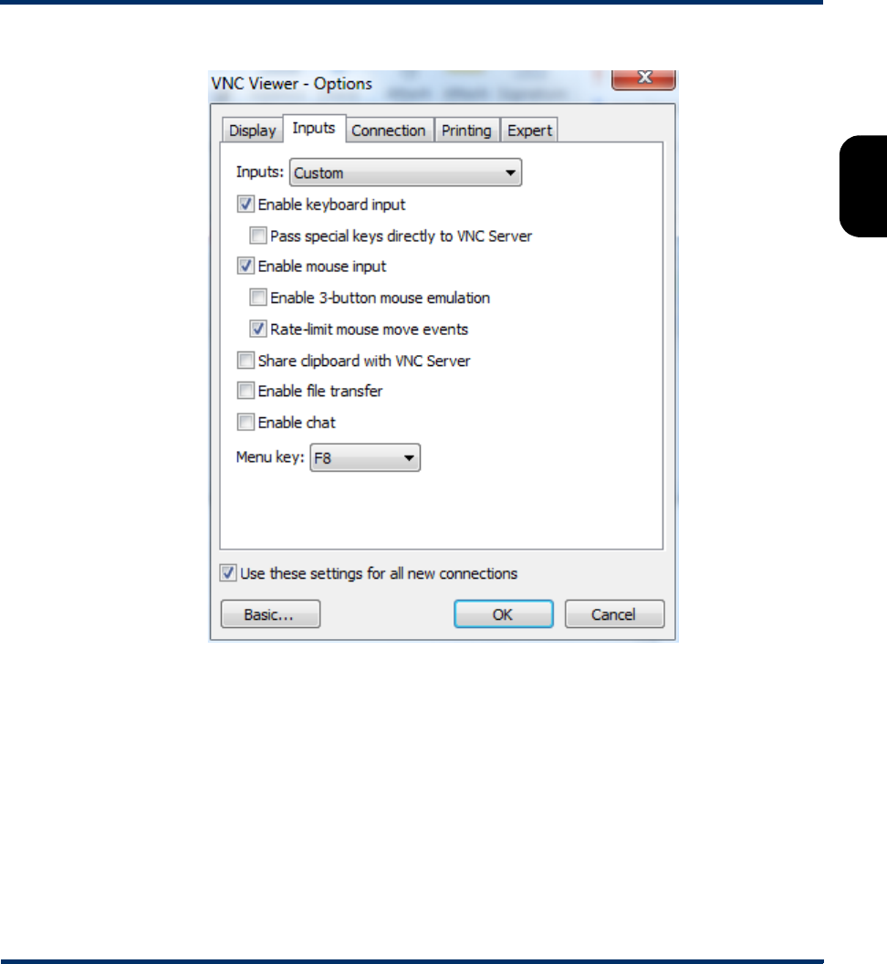
Tech-X Flex® (NG2) Tech-X Flex User Guide - Firmware v06.50
2-37
Intro
Overview
Wi-Fi
Ethernet
System
IP/Video
MoCA
RF
Specs
Figure 2-31 Advanced options - Inputs tab
Preliminary issue - Limited distribution only!
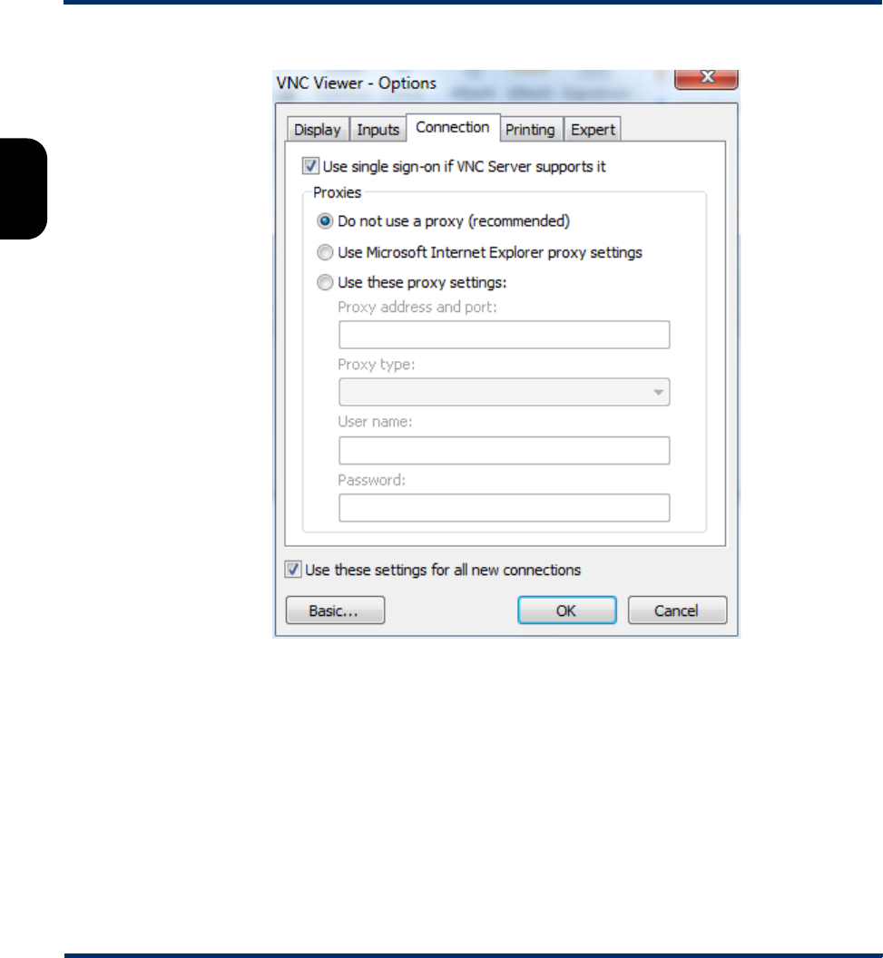
Tech-X Flex User Guide - Firmware v06.50 Tech-X Flex® (NG2)
2-38
Intro Overview Wi-Fi Ethernet System IP/Video MoCA RF Specs
Figure 2-32 Advanced options - Connection tab
Preliminary issue - Limited distribution only!
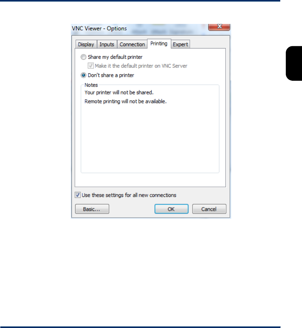
Tech-X Flex® (NG2) Tech-X Flex User Guide - Firmware v06.50
2-39
Intro
Overview
Wi-Fi
Ethernet
System
IP/Video
MoCA
RF
Specs
Figure 2-33 Advanced options - Printing tab
Preliminary issue - Limited distribution only!
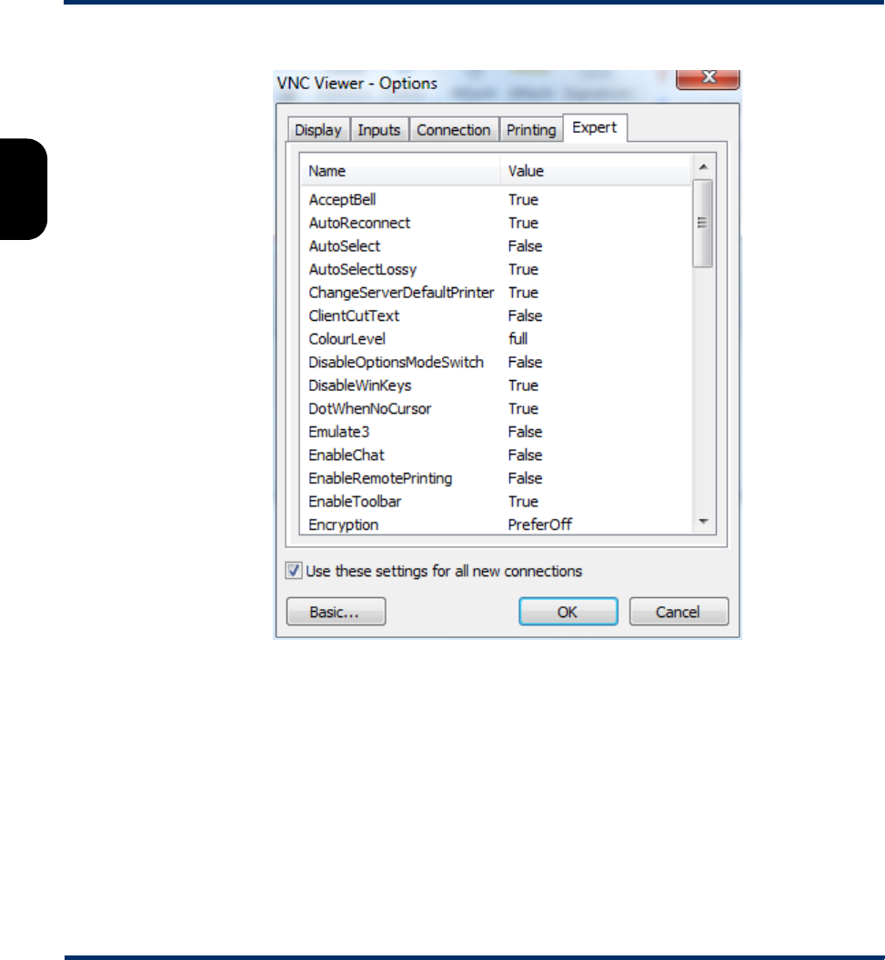
Tech-X Flex User Guide - Firmware v06.50 Tech-X Flex® (NG2)
2-40
Intro Overview Wi-Fi Ethernet System IP/Video MoCA RF Specs
Figure 2-34 Advanced options - Expert tab (First set)
Preliminary issue - Limited distribution only!
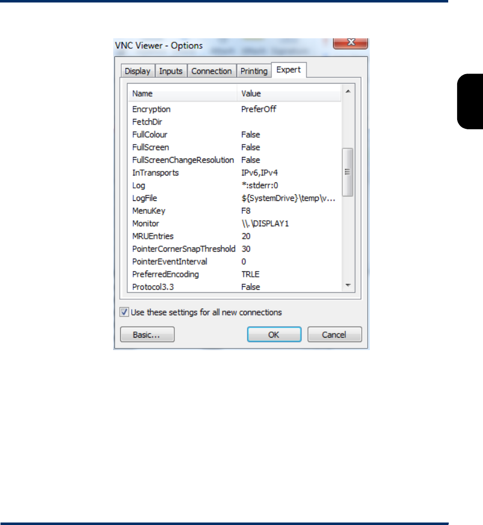
Tech-X Flex® (NG2) Tech-X Flex User Guide - Firmware v06.50
2-41
Intro
Overview
Wi-Fi
Ethernet
System
IP/Video
MoCA
RF
Specs
Figure 2-35 Advanced options - Expert tab (Second set)
Preliminary issue - Limited distribution only!
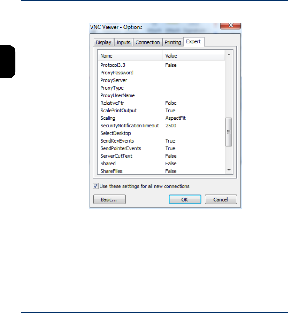
Tech-X Flex User Guide - Firmware v06.50 Tech-X Flex® (NG2)
2-42
Intro Overview Wi-Fi Ethernet System IP/Video MoCA RF Specs
Figure 2-36 Advanced options - Expert tab (Third set)
Preliminary issue - Limited distribution only!
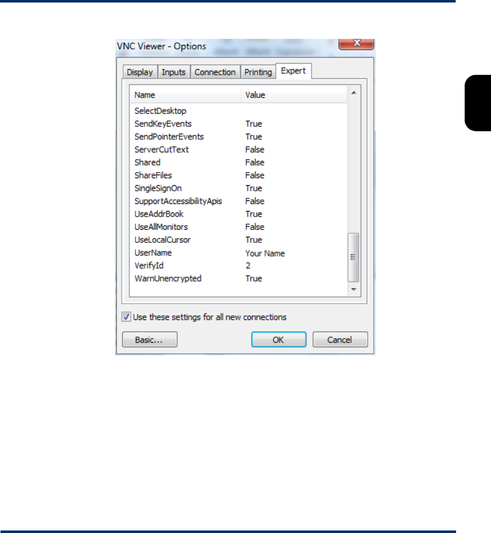
Tech-X Flex® (NG2) Tech-X Flex User Guide - Firmware v06.50
2-43
Intro
Overview
Wi-Fi
Ethernet
System
IP/Video
MoCA
RF
Specs
Figure 2-37 Advanced options - Expert tab (Fourth set)
2.5.3 Remote control setup scenarios
To establish a remote control session over VNC, an IP connection is required between the built-in VNC
server on the unit and a VNC client on a separate PC, tablet, or smartphone device. This IP connection
may be made using one of the following scenarios:
•Local remote control (via a router/LAN) setup on page 2-44
•Local remote control (via a Wi-Fi access point) setup on page 2-45
•Remote site remote control (via the internet) setup on page 2-46
Preliminary issue - Limited distribution only!
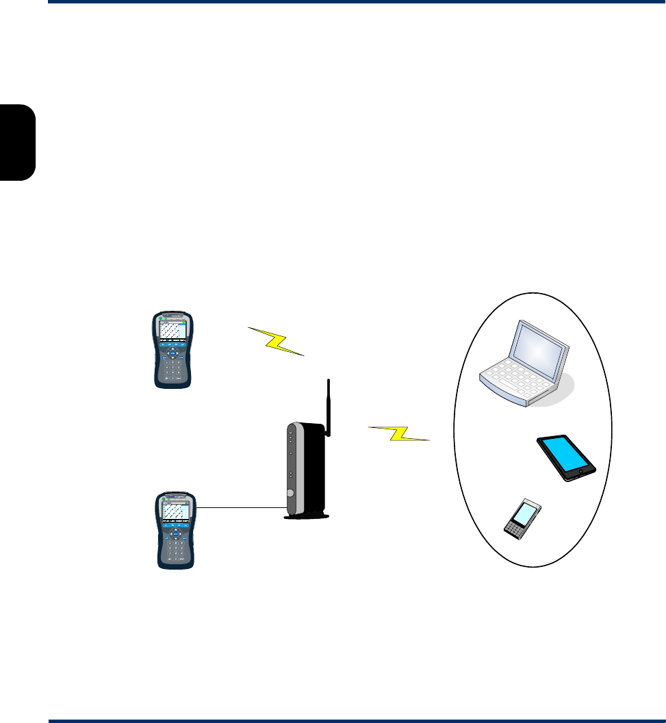
Tech-X Flex User Guide - Firmware v06.50 Tech-X Flex® (NG2)
2-44
Intro Overview Wi-Fi Ethernet System IP/Video MoCA RF Specs
Local remote control (via a router/LAN) setup
This setup is intended to allow local remote control over a residential LAN or similar. For example, it
might be used by a technician who needs to connect the unit at some point on a residential network, then
control the unit from elsewhere in the residence.
With this setup, the unit connects to a switch or router device (such as a BHR) with either:
• A Wi-Fi link, or
• An Ethernet/Cat-5 cable
The VNC client device then connects to same network (often through the same router), typically over a
standard Wi-Fi link. Once both devices are fully networked at the IP level, the VNC client application can
initiate a remote control session. Consider the following diagram which represents a typical residential
configuration with a BHR:
Figure 2-38 Remote control over an Admin Port connection
This type of remote control allows access to nearly all test and management functions on the unit,
including module testing menus. To set it up:
-or-
-or-
Wi-Fi
BHR
Wi-Fi
VNC
client
10/100
Admin Port
Ethernet
Wi-Fi
Admin Port
-or-
Preliminary issue - Limited distribution only!
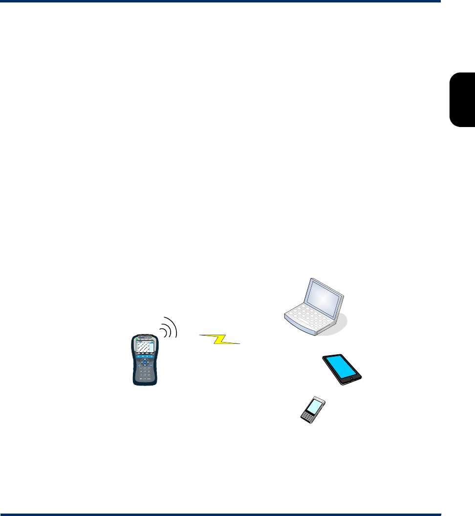
Tech-X Flex® (NG2) Tech-X Flex User Guide - Firmware v06.50
2-45
Intro
Overview
Wi-Fi
Ethernet
System
IP/Video
MoCA
RF
Specs
1. If you plan to use a 10/100/1G Admin Port, connect the unit to the router with a physical 10/100
(Ethernet) cable.
2. Set up a Wi-Fi Admin Port or a 10/100/1G Admin Port on the unit, as applicable (see Admin Port on
page 5-5).
NOTE: Remote control over a Wi-Fi Admin Port will not allow access to functions within the Wi-Fi
menu (F2).
3. Note the IP address that was assigned and then initiate the VNC session on the client device (see
Initiating a VNC connection on the client on page 2-49).
Local remote control (via a Wi-Fi access point) setup
NOTE: This feature is available as a purchasable option. For more information, see Licensed feature
details on page 2-53.
This setup allows local remote control over a direct wireless connection to the unit, where the unit sets up
a small Wi-Fi network to which another device can connect. As an example, it might be used by a
technician who needs to physically connect the unit at some point on a residential network, then control
the unit from elsewhere in the residence. Because the devices connect directly, it may be more
convenient than using the residential LAN to establish connectivity.
Figure 2-39 Remote control via a Wi-Fi access point
To establish the access point, select System > Admin Port > Wi-Fi Admin Port > AP Remote Control.
The process launches immediately and the unit presents a results screen that includes its SSID and IP
address:
-or-
-or-
Normal Wi-Fi VNC
client
Wi-Fi access
point
Preliminary issue - Limited distribution only!
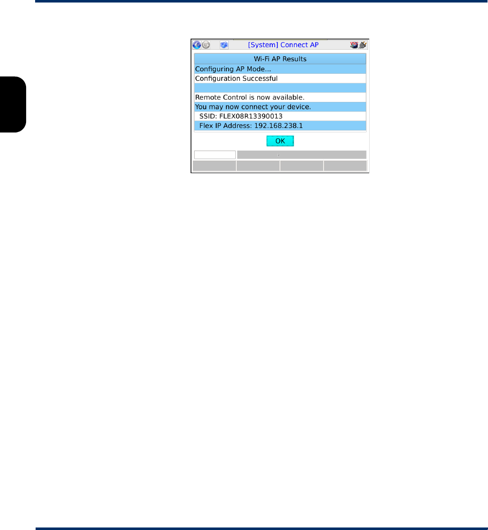
Tech-X Flex User Guide - Firmware v06.50 Tech-X Flex® (NG2)
2-46
Intro Overview Wi-Fi Ethernet System IP/Video MoCA RF Specs
Figure 2-40 AP Remote Control results screen
Afterwards, you can use any Wi-Fi enabled device to connect to the network using standard methods.
The network is unsecured and requires no credentials, other than knowledge of the SSID. Once
connected, use the IP address shown to initiate the VNC connection, 192.168.238.1 in this example.
Note that a unit access point will only provide a single IP address, so only a single device may connect to
its network at any given time.
Remote site remote control (via the internet) setup
NOTE: This feature is available as a purchasable option. For more information, see Licensed feature
details on page 2-53.
With this setup, the unit can be controlled over an internet connection, perhaps by a technician in a
remote support center. It assumes that the unit is connected on a LAN behind a UPnP-enabled router,
whose WAN side interface is configured with a public IP address. For example:
Preliminary issue - Limited distribution only!
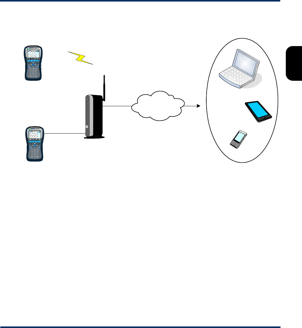
Tech-X Flex® (NG2) Tech-X Flex User Guide - Firmware v06.50
2-47
Intro
Overview
Wi-Fi
Ethernet
System
IP/Video
MoCA
RF
Specs
Figure 2-41 Remote control over an internet connection
This type of remote control allows access to nearly all test and management functions on the unit unless
you connect the unit over a Wi-Fi Admin Port, in which case all functions within the Wi-Fi menu (F2) will
be unavailable. To set it up:
1. At the subscriber site, if you plan to use a 10/100/1G Admin Port, connect the unit to the router with
a physical 10/100 (Ethernet) cable.
2. On the unit, set up a Wi-Fi Admin Port or a 10/100/1G Admin Port port (respectively) with
connectivity to the LAN, in a standard manner. For more information, see Admin Port on page 5-5.
3. Select System > Admin Port > WAN Remote Control > Enable WAN Remote Control. Note that
this step configures the router, in order to establish a VNC traffic path to the unit.
4. In the Enable WAN Remote Control results, make note of the following information which will be
required for the remote VNC client user:
•External IP Address - The address assigned to the WAN interface
•External VNC Port - The port that incoming VNC traffic must use
-or-
-or-
VNC
client
LAN
port
WAN
port
Internet
BHR
Wi-Fi
10/100
Admin Port
Ethernet
Wi-Fi
Admin Port
-or-
Preliminary issue - Limited distribution only!
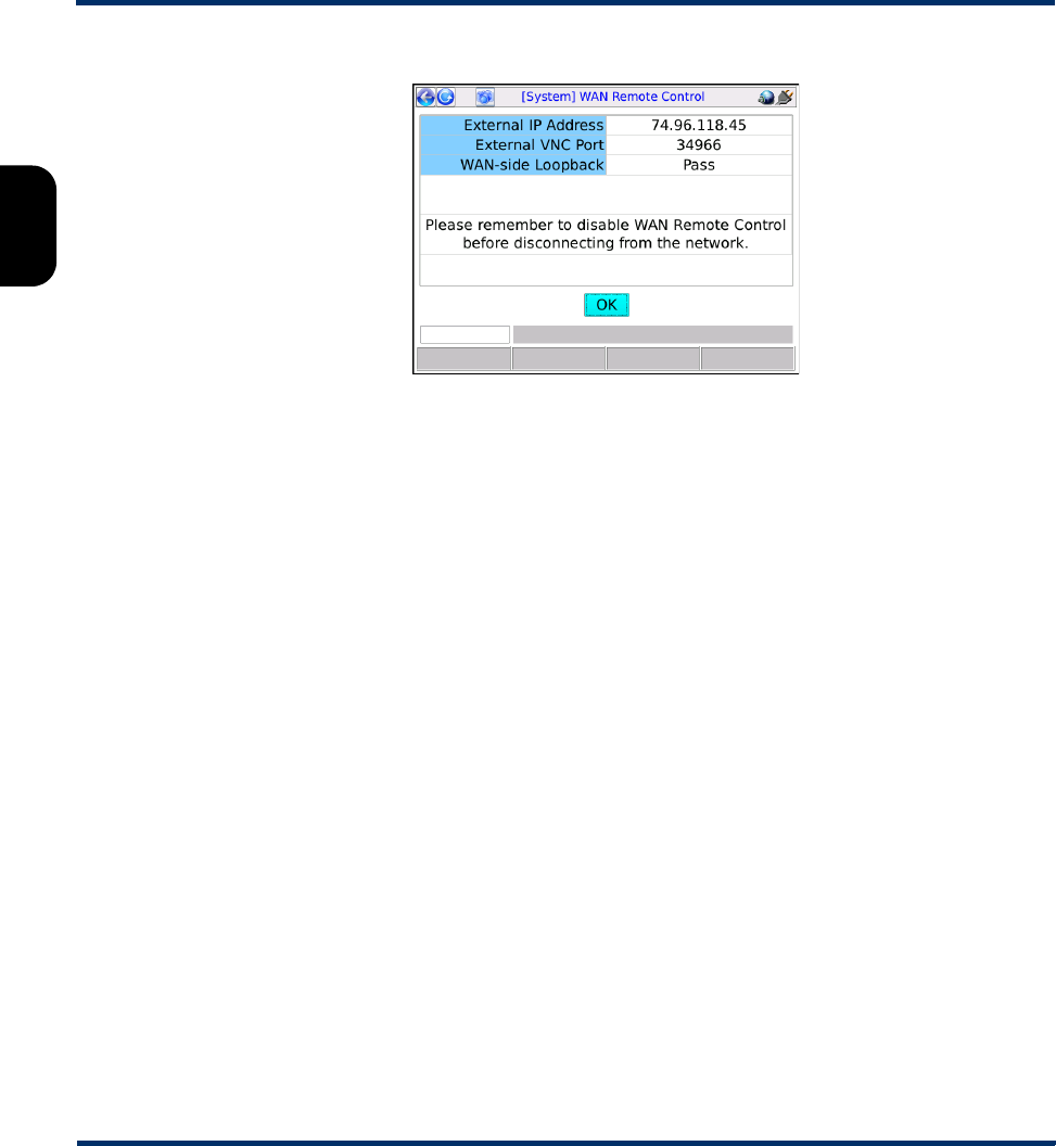
Tech-X Flex User Guide - Firmware v06.50 Tech-X Flex® (NG2)
2-48
Intro Overview Wi-Fi Ethernet System IP/Video MoCA RF Specs
Figure 2-42 Enable WAN Remote Control results screen
Note the following:
• If this function fails, the router may not support UPnP management or it may have been
configured in a manner that prevents the unit from performing the necessary tasks. Router
administration is beyond the scope of this document. If you continue to have trouble, consult the
router documentation and/or a network specialist.
• In rare cases, this function will pass but report an address of 0.0.0.0. Again, certain router
configurations may cause this behavior. If you already know or can determine a valid WAN side
address, VNC control may still be possible.
• Following the router configuration, the unit attempts a test connection with the WAN interface,
using the newly-configured path. If the test is successful, it reports Pass for WAN-side
Loopback, which generally indicates that the path from the interface to the unit is good.
Otherwise, it reports Fail; however, note that hardware limitations and/or other anomalies may
obstruct the test and that the path may still be good. In other words, a result of Fail does not
necessarily indicate a problem and you should always attempt the VNC session anyway.
5. Forward the IP address and port to the remote VNC user, who must then launch a VNC session with
those parameters (see Initiating a VNC connection on the client on page 2-49).
6. When the VNC session is complete, select System > Admin Port > WAN Remote Control >
Disable WAN Remote Control to restore the router to its original configuration.
Additional technical details
This remote control functionality is based on port-forwarding technology that is typically supported by
residential routers. In summary, a router can be configured to accept packets at its public WAN address
using a specific port, then translate to a different port and forward the packets to a specific (non-public)
host on the LAN. In this manner, standard firewalls can remain in place, with a path for very specific traffic
to reach a specific LAN host.
Preliminary issue - Limited distribution only!

Tech-X Flex® (NG2) Tech-X Flex User Guide - Firmware v06.50
2-49
Intro
Overview
Wi-Fi
Ethernet
System
IP/Video
MoCA
RF
Specs
In this case, the traffic is VNC and the host is the unit, whose VNC server expects traffic on port 5900.
During the Enable WAN Remote Control step, the unit configures the router to accept traffic on some
other port (as reported for External VNC Port) and forward the traffic to its LAN address on port 5900. In
this way, the unit appears to the VNC client as any other host on the internet and full VNC functionality is
supported. Note that this general methodology is commonly used by other devices such as internet-
based gaming systems, where non-public hosts must communicate with one another across the internet.
These systems automatically configure their respective routers much like the unit.
With respect to the persistence of the router configuration, note the following:
• If you never manually undo the router configuration (Disable WAN Remote Control), the forwarding
path may remain indefinitely. This may or may not be of concern. While it represents a path through
the firewall that did not exist previously, its scope is limited to traffic on port 5900 reaching the
address that the unit was using during the VNC session. A network administrator should provide
advice and procedures related to this possibility.
•The Disable WAN Remote Control setting is always enabled, in the event that it must be executed
some time in the future, perhaps some time after the end of the VNC session.
• Port forwarding can be manually configured through the administrative interface of a router. If you
use this interface to make changes to settings that were configured by the unit, the Disable WAN
Remote Control function may fail afterwards. Therefore, it is strongly recommended to allow the unit
to perform all router configuration tasks and to use the router interface only if absolutely necessary.
The unit uses UPnP (Universal Plug and Play) technology when configuring the router. UPnP has other
applications as well. For more information, see http://www.upnp.org/.
2.5.4 Initiating a VNC connection on the client
To initiate a VNC connection and thus begin a remote control session, you must first:
1. Be sure that a functional VNC client is properly installed on the client device (see Installing a VNC
client (viewer) on page 2-34).
2. Establish IP connectivity with the unit in a manner suitable for VNC control (see Remote control setup
scenarios on page 2-43).
Once these steps are complete and you know the IP address assigned to the unit, you can initiate a VNC
session as follows:
Initiating a VNC session with RealVNC
Preliminary issue - Limited distribution only!
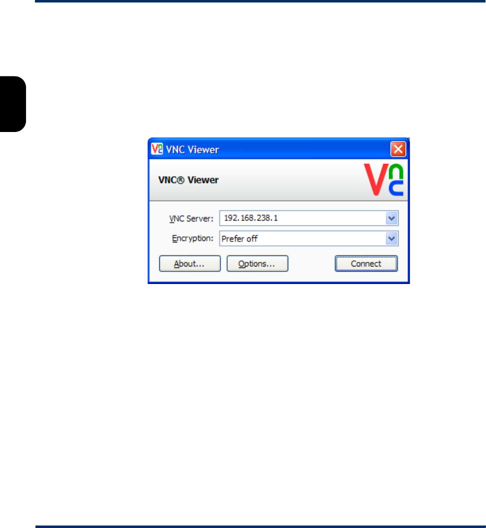
Tech-X Flex User Guide - Firmware v06.50 Tech-X Flex® (NG2)
2-50
Intro Overview Wi-Fi Ethernet System IP/Video MoCA RF Specs
1. In the initial setup screen that appears when you launch the viewer, enter the IP address of the unit
and click OK.
NOTE: If you are connecting over the internet using the WAN Remote Control feature, you must
include a colon and the port expected on the subscriber router WAN interface. Otherwise, the
application will use the standard VNC port 5900, which will not transit the router. For more
information on internet-based remote control, see Remote site remote control (via the internet)
setup on page 2-46.
Figure 2-43 RealVNC v5.0.5 setup screen - Local remote control example
Preliminary issue - Limited distribution only!
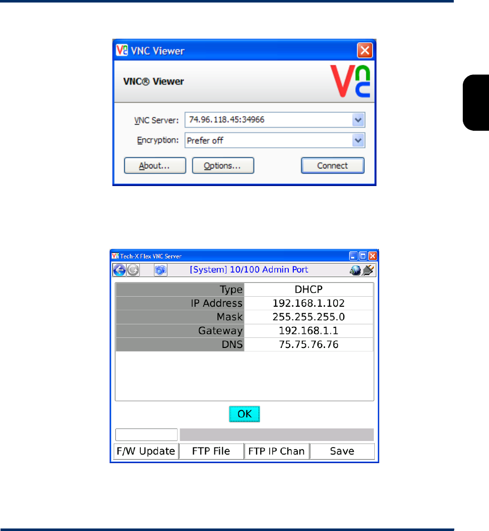
Tech-X Flex® (NG2) Tech-X Flex User Guide - Firmware v06.50
2-51
Intro
Overview
Wi-Fi
Ethernet
System
IP/Video
MoCA
RF
Specs
Figure 2-44 RealVNC v5.0.5 setup screen - Internet (remote site) remote control example
2. When the VNC window appears, operate the unit using the computer mouse, keyboard, etc. as if
operating the unit directly.
Figure 2-45 RealVNC window showing the unit screen
Initiating a VNC session with Mocha VNC Lite
Preliminary issue - Limited distribution only!
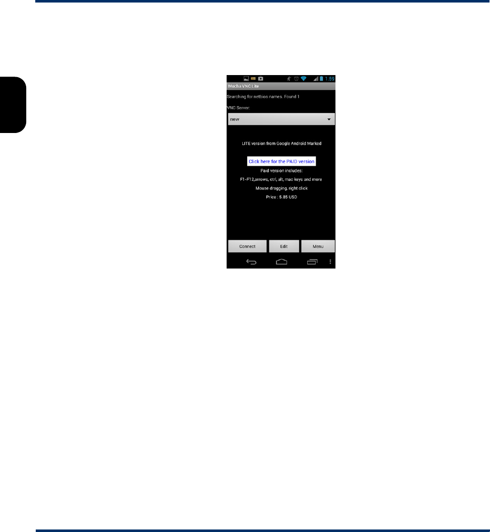
Tech-X Flex User Guide - Firmware v06.50 Tech-X Flex® (NG2)
2-52
Intro Overview Wi-Fi Ethernet System IP/Video MoCA RF Specs
1. On the mobile device, make sure that the Wi-Fi interface is enabled. Refer to the documentation of
the specific device for more information.
2. Launch Mocha Lite.
Figure 2-46 Mocha VNC Lite initial setup screen
3. Tap Edit in the initial setup screen.
4. In the Edit session screen, configure the following:
•VNC Server IP - Enter the IP address of the unit.
•Password - Enter a pound sign (#) to indicate that no password is required.
•Port - Specify the destination TCP port, typically either:
The default of 5900 when using local remote control over a LAN or an ad hoc Wi-Fi network, or
The port reported for External VNC Port in the Enable WAN Remote Control results, when
controlling the unit over the internet (see Remote site remote control (via the internet) setup on
page 2-46).
...and tap Ok.
Preliminary issue - Limited distribution only!
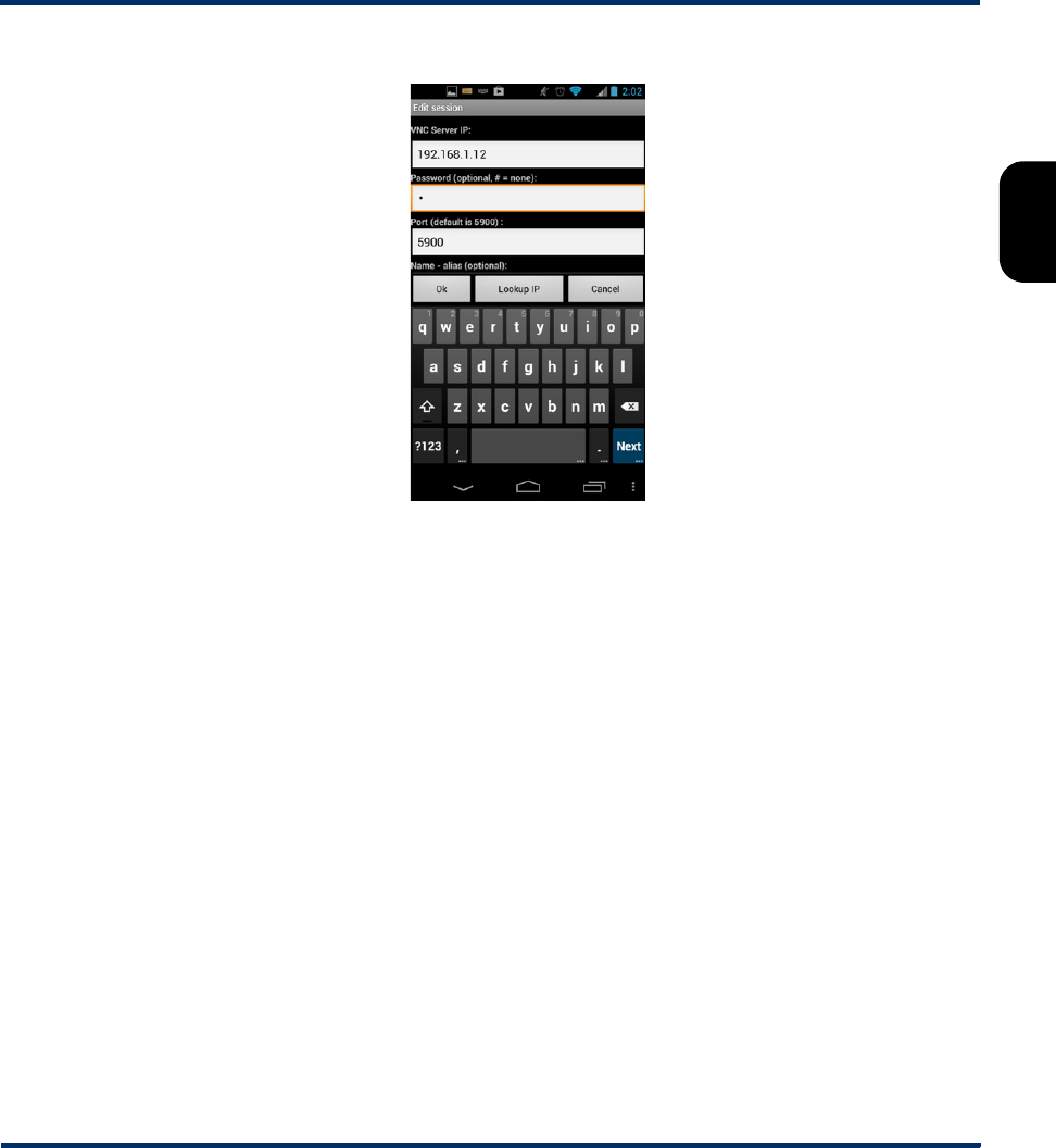
Tech-X Flex® (NG2) Tech-X Flex User Guide - Firmware v06.50
2-53
Intro
Overview
Wi-Fi
Ethernet
System
IP/Video
MoCA
RF
Specs
Figure 2-47 Mocha VNC Lite Edit session screen
5. When the VNC window appears, operate the unit using the mobile device touchscreen as if operating
the unit directly.
NOTE: Remember that you can double-tap any text entry field to produce the unit keypad, just like
when using the actual unit touchscreen.
2.6 Licensed feature details
The following table provides details on the optional licenses available for purchase and the specific
features that they control. Any feature not explicitly listed is normally functional without a special license
or license key. Note the following:
• In most cases, general module functionality does not require a separate license, as the purchase of
the physical hardware is considered a general operational license. However, some specific features
of certain modules may require a license.
• At any time, you can use the System menu to view the status of current licenses and enable features
with new license keys. For more information, see Licensed Options on page 5-12.
Preliminary issue - Limited distribution only!

Tech-X Flex User Guide - Firmware v06.50 Tech-X Flex® (NG2)
2-54
Intro Overview Wi-Fi Ethernet System IP/Video MoCA RF Specs
Table 2-12 License details
License Affected hardware
component Description
Constellation MoCA/RF module Enables the constellation graph for RF testing (see
About QAM and the constellation graph on
page 8-18).
Dual Ethernet Base unit Enables passive testing on the 10/100/1G interface.
More specifically, it allows the unit to be connected
in-line with an existing Ethernet link and mirror traffic
internally for analysis. Without this license, both
10/100/1G ports will operate normally for any other
type of testing, including the ability to bridge an
existing Ethernet link, but without traffic mirroring.
For more information, see Passive testing on
page 4-4.
Dual MoCA MoCA/RF module Allows the MoCA module to synchronize “in-line”
with a MoCA network; that is, act as a bridge for the
purpose of analyzing network traffic and related
testing. Without this option, the unit supports single-
port synchronization in a single direction only and
the Join MoCA Network In-Line menu item is
disabled. For more information, see Join MoCA
Network In-Line (Bridging and passive testing) on
page 7-19.
High Speed Data All Enables the use of the All Devices Packet Loss
test on all applicable IP interfaces. For more
information, see All Devices Packet Loss (Device
Discovery) on page 6-19.
IP Video All Enables IP video quality and channel change testing
on all applicable interfaces. For more information,
see IP Video testing on page 6-22.
L4 Performance
Testing
All Enables iPerf-based TCP testing (see L4
Performance Test on page 6-7).
Preliminary issue - Limited distribution only!

Tech-X Flex® (NG2) Tech-X Flex User Guide - Firmware v06.50
2-55
Intro
Overview
Wi-Fi
Ethernet
System
IP/Video
MoCA
RF
Specs
2.7 Maintenance
The only maintenance task that should be performed by users is battery replacement. For all other
maintenance requirements, return the unit to Spirent. Do not remove the cover of the unit during battery
replacement or at any other time. For more information on battery replacement, see Battery
installation/replacement on page 2-55.
2.7.1 Battery installation/replacement
A new unit may require the battery to be installed before its first use. Additionally, users may perform field
replacement of the battery pack as necessary. No tools are required. Note the following:
Remote Control Base unit Enables the following commands:
•System > Admin Port > Wi-Fi Admin Port > Ad-
Hoc Remote Control
•System > Admin Port > WAN Remote Control
For more information, see Remote control of the unit
on page 2-33.
RF Testing MoCA/RF module Enables overall RF testing (see MoCA/RF - RF
Testing on page 8-1).
Web Browser All Enables the internet web browser on all applicable
interfaces.
Wi-Fi Base unit Enables the Wi-Fi testing menu as well as the ability
to establish a Wi-Fi Admin Port (see Admin Port on
page 5-5).
Wi-Fi Spectrum Base unit Enables the Wi-Fi Spectrum Analysis (see Wi-Fi
Spectrum Analysis on page 3-17).
Any other licenses
listed in the Licensed
Options screen
- - - Related to beta, customer-specific, or in-
development features and are normally not relevant
to general users.
License Affected hardware
component Description
Preliminary issue - Limited distribution only!
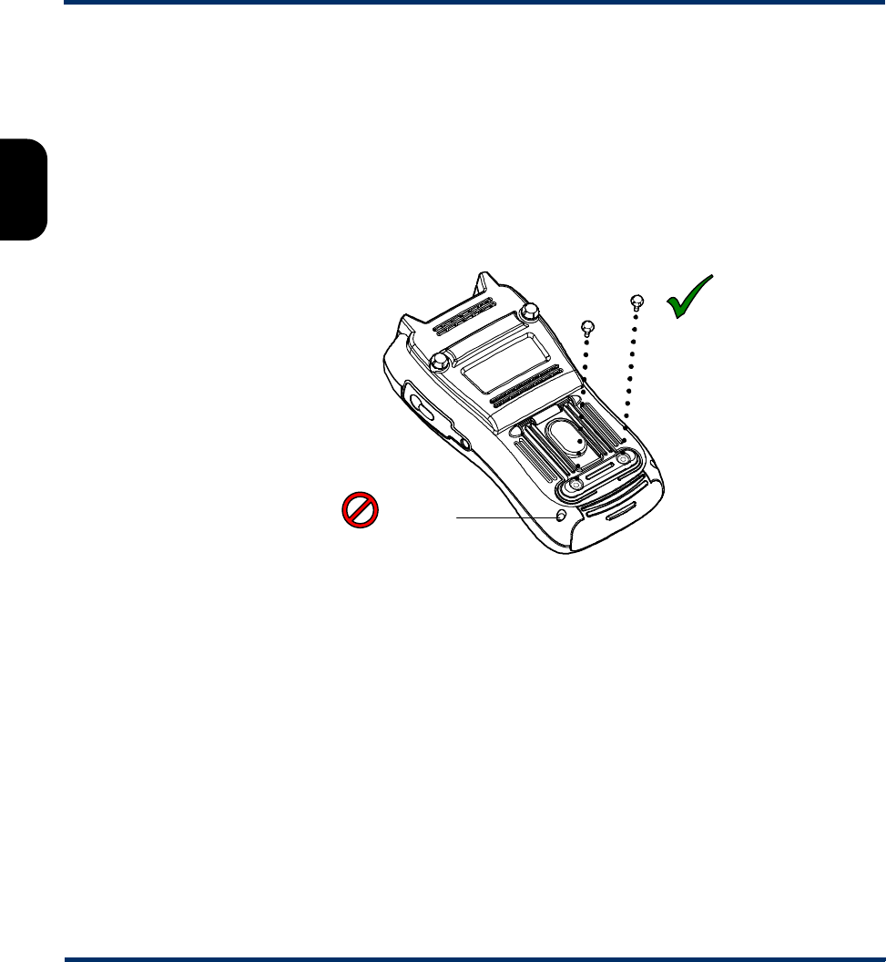
Tech-X Flex User Guide - Firmware v06.50 Tech-X Flex® (NG2)
2-56
Intro Overview Wi-Fi Ethernet System IP/Video MoCA RF Specs
• New battery packs should be ordered from Spirent (MPL# T5411). The use of any other battery
could damage the unit and create a safety hazard for users.
• Batteries contain hazardous contaminants and should be disposed of according to local regulations.
It may be illegal to discard batteries in the general trash.
To replace the battery pack
1. On the back of the unit, remove the two battery pack hand screws at the base of the kickstand. Be
careful not to accidentally remove the unit cover screws which require a screwdriver (see Figure 2-
48).
Figure 2-48 Battery pack screws
2. Gently slide the old battery pack out (with the cradle) from the bottom of the unit and insert the new
battery pack. For new units, the battery chamber may have a placeholder instead which can be
discarded once a battery is installed.
Battery pack
screws
Unit cover
screw
Preliminary issue - Limited distribution only!

Tech-X Flex® (NG2) Tech-X Flex User Guide - Firmware v06.50
2-57
Intro
Overview
Wi-Fi
Ethernet
System
IP/Video
MoCA
RF
Specs
Figure 2-49 Inserting a battery pack
3. Following battery insertion, reinstall the hand screws.
NOTE: Do not overtighten the screws, which could cause the plastic to crack.
2.8 FTP information
The unit has several features that may involve transferring files to and/or from the unit. In most cases,
this transfer is handled by an FTP operation, during which the unit acts as an FTP client, invoking
functions on an external FTP server. Therefore, to complete an FTP exchange, you must have an FTP
server installed, properly configured, and actively running on a computer that is networked to the unit.
This section describes general information associated with FTP server setup. Information about specific
file transfer operations is provided elsewhere in this document as appropriate.
2.8.1 Admin Port setup
Before any FTP action is possible, you must have the Admin Port configured with routable IP
information. This port is effectively the gateway to the “outside world.” For more information, see Admin
Port on page 5-5.
Preliminary issue - Limited distribution only!

Tech-X Flex User Guide - Firmware v06.50 Tech-X Flex® (NG2)
2-58
Intro Overview Wi-Fi Ethernet System IP/Video MoCA RF Specs
2.8.2 FTP server installation and setup
Currently, the only extensively tested and approved FTP server is FileZilla, a free, open-source
application available at http://filezilla-project.org/ at the time of this writing. The FileZilla server runs on
the Windows platform only and may run on any Windows computer. Typically, a networked desktop PC is
the best choice to host the server.
The primary tasks involved with server setup are generally performed one time and include:
• Installation of the server software
• The configuration of one or more user accounts for the server, which the unit will use to log in and
transfer files.
To set up FileZilla on a host computer:
1. Download the FileZilla server installation package (not the client).
2. Launch the package and install according to default settings, unless customization is desired. In the
installation wizard, note that the Port option applies to the server management port, not the FTP
listening port. In most cases, the default of 14147 is adequate.
3. Open the server management interface, normally with a new icon on the desktop or perhaps Start >
FileZilla Server > FileZilla Server Interface. If you are running the server on a local computer, the
default Server Address and Port should be correct. For new installs, you can leave the password
blank.
4. In the interface window, select Edit > Users.
5. In the Users window, click Add to add a new FTP user account, which the unit will use to transfer
files to and/or from the computer.
6. In the Add user account window, specify a user name (such as techFLEX_ALL) and click OK. This
user name will be a required entry when the file transfer is initiated on the unit. It is good practice to
set up separate user accounts for each transfer activity required by the unit, such as channel guide
import versus results export.
7. Back in the Users window, under Page, click the General page link and create a password if desired.
Important! The password is optional. If you create one, it will be required when a file transfer is
initiated on the unit.
8. In the Users window, under Page, click the Shared folders page link, then under Shared folders
click Add to specify a home folder for the user account. When an FTP connection is established for
this account, this is the default folder from which files are transferred.
NOTE: Some unit FTP activities involve the transfer of data from the unit to the FTP server, in
which case you should be sure to click the Write checkbox under Files, for the shared folder you
added. By default, new user accounts have writing disabled, which will cause any export function
from the unit to fail.
Preliminary issue - Limited distribution only!
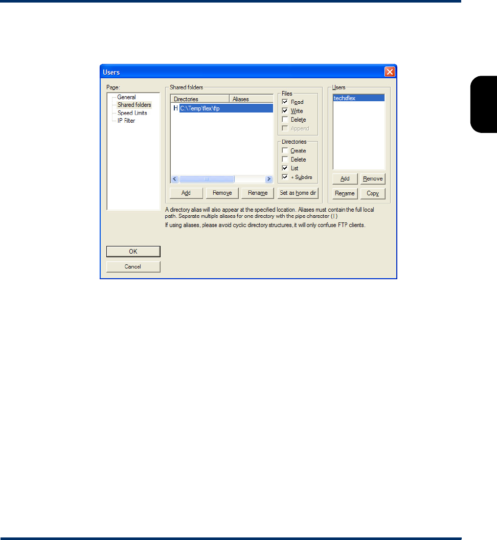
Tech-X Flex® (NG2) Tech-X Flex User Guide - Firmware v06.50
2-59
Intro
Overview
Wi-Fi
Ethernet
System
IP/Video
MoCA
RF
Specs
At this point, the user account should be complete. The dialog box should appear something like the
following:
Figure 2-50 Completed user account in FileZilla
9. In the Users window, click OK to save the new user.
10. Back in the management interface, if necessary select Server > Active to ensure that the server is
actively listening for FTP requests.
NOTE: FileZilla includes a variety of configuration options, including whether to automatically launch
and enable the server upon Windows startup. Further information is beyond the scope of this
document. See the FileZilla documentation for more information.
2.8.3 FTP connection parameters
When an FTP-related operation is invoked, the unit requires standard connection parameters to reach
the FTP server and perform the file transfer. These parameters may include:
Preliminary issue - Limited distribution only!

Tech-X Flex User Guide - Firmware v06.50 Tech-X Flex® (NG2)
2-60
Intro Overview Wi-Fi Ethernet System IP/Video MoCA RF Specs
Server IP address or domain name of the computer where the FTP server is running. This
computer will be the source for any files transferred to the unit and/or the
destination for any files transferred from it. The specific folder on the computer is
generally determined by the user account configured as described under FTP
server installation and setup on page 2-58 and specified below (User ID).
Port TCP port used by the FTP server, typically 21 (standard FTP port). The server port
can be changed in the server management application - see the server
documentation for more information.
User ID
Password
FTP authentication information, valid for a user account currently configured on
the FTP server. This account will be associated with a folder on the server
computer where files will be transferred to or from. For more information, see FTP
server installation and setup on page 2-58.
Server Folder Subfolder where files should be transferred to or from, relative to the user folder
configured as described under FTP server installation and setup on page 2-58.
This parameter is only applicable to some unit functions and may be optional. If it
remains unspecified or does not appear at all, all files will be transferred to or from
the “home directory” associated with the FTP user account (User ID).
Ping Before
Transfer
Runs a ping test to the server computer before the FTP attempt. If all ping
attempts fail, the FTP attempt is aborted. Not all FTP-related operations support
this parameter.
Admin port
information
FTP transaction screens also normally include information about the Admin Port,
which is the interface through which the FTP transaction will occur. If the FTP
action is a “download” action where a file is transferred to the unit, this information
is normally found in a Destination tab. Otherwise, it is found in a Source tab. In
either case, the screen provides:
• IP information about the currently-established Admin Port, if there is one.
-and-
• Buttons to set up an Admin Port which transport you to the standard Admin
Port setup screen, after which you will be returned to the applicable FTP
screen.
In all cases, you must have an Admin Port configured to complete the FTP
transaction, whether you have configured it beforehand or through the shortcuts in
the FTP area.
Preliminary issue - Limited distribution only!

Tech-X Flex® (NG2) Tech-X Flex User Guide - Firmware v06.50
2-61
Intro
Overview
Wi-Fi
Ethernet
System
IP/Video
MoCA
RF
Specs
2.8.4 FTP connection troubleshooting
Following an FTP attempt, the unit will report whether the action was successful. If the attempt fails,
ensure that:
• You are using an approved FTP server and that it is configured correctly.
• You have specified the FTP input parameters exactly right. A single character mistake in any of them
will cause a connection failure.
• The FTP server computer and the unit have IP-level connectivity. Either device should be able to ping
the other.
• The traffic between the unit and the FTP server is not blocked by a firewall. In particular, if the FTP
server is on a Windows computer, it is not uncommon for the default settings of an active Windows
Firewall to prevent the transfer. When a firewall blocks FTP activity, the server administration
interface will show zero activity while the unit is attempting the transfer, because there is ultimately no
connection between the two entities.
Firewall configuration is beyond the scope of this document. For more information, see the Windows
Firewall documentation, the FTP server documentation, and/or contact an IT administrator.
2.9 Technical support
If you need product assistance or want to report problems with the product or the documentation, please
contact us.
E-mail: support@spirent.com
Phone:
North America 1-800-SPIRENT
China +86 (10) 8233 0033
China mainland only +86 (800) 810-9529
France +33 (1) 6137 2270
UK (EMEA TAC) +44 1803 546333
Preliminary issue - Limited distribution only!

Tech-X Flex User Guide - Firmware v06.50 Tech-X Flex® (NG2)
2-62
Intro Overview Wi-Fi Ethernet System IP/Video MoCA RF Specs
Preliminary issue - Limited distribution only!
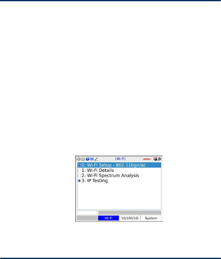
Tech-X Flex® (NG2) Tech-X Flex User Guide - Firmware v06.50
3-1
3: Wi-Fi Testing Menu
Wi-Fi testing on the unit includes:
• Scanning for available wireless access points
• Connecting to an existing network and obtaining IP information
• Basic network-level testing such as ping, traceroute, and web browsing
All Wi-Fi testing is performed from the Wi-Fi menu. When this menu is active, all testing uses the Wi-FI
interface only. That is, no other interface will process test requests.
NOTE: You must have a Wi-Fi connection established before any other Wi-Fi functions become
available. Furthermore, when you leave the Wi-Fi menu, the Wi-Fi interface is shut down and
the existing connection, if any, is dropped unless you have the unit configured to keep the
interface active.
Figure 3-1 Wi-Fi main menu (T5300 units)
Preliminary issue - Limited distribution only!
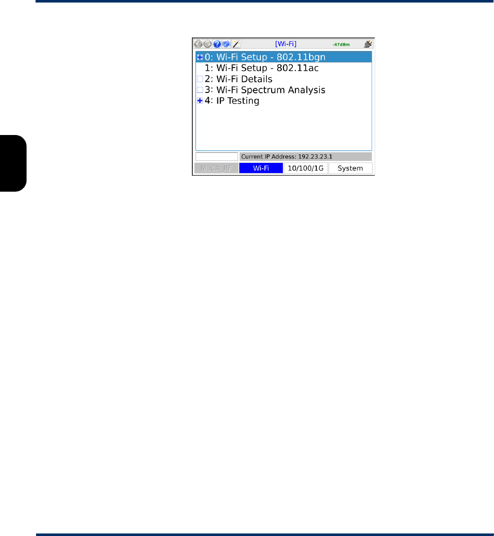
Tech-X Flex User Guide - Firmware v06.50 Tech-X Flex® (NG2)
3-2
Intro Overview Wi-Fi Ethernet System IP/Video MoCA RF Specs
Figure 3-2 Wi-Fi main menu (T5100) units
3.1 Important wireless 802.11ac note (T5100 models only)
For T5100 models only, when the unit is actively transmitting in 802.11ac mode, the unit should
be placed on a horizontal surface with a minimum distance of 20 cm from any part of a human
body. Note that this restriction only applies when the unit is actively connected to a network, not while
scanning for networks. Other modes (for example, 2.4 GHz 802.11b/g/n) do not involve any such
restrictions.
3.2 Functionality note
Wi-Fi connection and testing is a purchasable option. Please contact Spirent for more information.
3.3 Wi-Fi overview
The following sections describe general information about the unit and Wi-Fi.
3.3.1 Wi-Fi support details
The unit supports:
• Connection to IEEE 802.11 standards including b, g, n, and ac.
• Open and secured networks, including:
Preliminary issue - Limited distribution only!
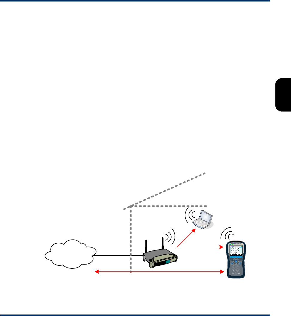
Tech-X Flex® (NG2) Tech-X Flex User Guide - Firmware v06.50
3-3
Intro
Overview
Wi-Fi
Ethernet
System
IP/Video
MoCA
RF
Specs
– Wired Equivalent Privacy (WEP) authentication, both WEP-64 (40-bit key) and WEP-128 (104-bit
key)
– Wi-Fi Protected Access (WPA and WPA2) authentication, using pre-shared key (PSK) mode
NOTE: The unit cannot connect to a network that does not broadcast its SSID. A network such as this
may appear within Scan results; however, the controls related to connection will be disabled.
By emulating a wireless PC in the home, you can perform troubleshooting activities such as:
• Verifying ISP availability and therefore ruling out the provider network as the cause of internet
connectivity problems. If the unit can access the internet but a subscriber PC cannot, it is likely that
the problem resides in the PC and/or its wireless interface.
• Determine whether Wi-Fi “dead zones” exist at the premises and whether they are affecting network
performance. In some cases, wireless network troubles may be caused by equipment that is simply
out-of-range of the source.
Detailed technical information about Wi-Fi and 802.11 is beyond the scope of this document. If you are
having trouble connecting, see If you cannot connect (troubleshooting tips) on page 3-4.
3.3.2 Wi-Fi testing diagram
The following diagram shows a typical setup for Wi-Fi testing.
Figure 3-3 Typical Wi-Fi testing diagram
Ping, traceroute, web browsing
Provider
network/ISP
Wireless
router
Home
computer
Ping
Preliminary issue - Limited distribution only!

Tech-X Flex User Guide - Firmware v06.50 Tech-X Flex® (NG2)
3-4
Intro Overview Wi-Fi Ethernet System IP/Video MoCA RF Specs
3.3.3 If you cannot connect (troubleshooting tips)
If you are in range of a wireless access point but cannot connect, verify the following:
• If entering all information manually, you have properly identified the network. Because this is an error-
prone process, it is recommended that you use the auto-scan feature to find the network and
prepopulate many of the parameters (see Wi-Fi Setup > Scan on page 3-5.)
• The network is not an “ad hoc” network, which the unit does not support within the normal Wi-Fi
menu tools.
• You have identified the proper security protocol in use and have the necessary information for
connection. If the network uses WEP or WPA-PSK, you must have the required authentication
information. If it uses a different protocol that the unit does not support, such as WPA-EAP or MAC
address restrictions, you will not be able to connect.
3.3.4 About WPS support
The unit supports several Wi-Fi Protected Setup (WPS) options for connection. To enable WPS, select
Security Type=WPA-WPS in the connection setup screen, then one of the following for Key Type:
•PUSHBUTTON - This option prepares the unit for normal WPS “pushbutton” mode. When the
connection parameters are submitted, the unit will first prompt you to press the WPS button on the
wireless gateway/router. Once the button is pushed, you should dismiss the prompt and allow the
connection to proceed. Be sure to complete the process before the gateway/router times out and
denies access to the unit.
•PIN - This option assumes that a WPS PIN is pre-configured on the gateway/router, using its
administrative tools. You must know what the PIN is. To connect, enter the PIN in the Key field and
submit the connection request. If the PIN is specified correctly, the gateway/router should allow the
connection. See the gateway/router documentation for more information on configuring WPS PINs.
•GENERATE PIN - This option is similar to the PIN option, except that it assumes that no PIN is
currently configured on the gateway/router for the device. When you submit the connection
parameters, the unit will present a prompt with the PIN to use, which must then be entered into the
gateway/router WPS configuration. Once configured, you should dismiss the prompt on the unit and
allow the connection to proceed. Again, see the gateway/router documentation for more information
on configuring WPS PINs.
Upon a successful WPS connection, the unit attempts to store the underlying WPA authentication
information for the link. Afterwards, the unit can rejoin the network without the WPS step. This feature is
the most useful for pushbutton mode, allowing you to bypass the button push for all subsequent attempts
to join the network.
Note the following:
Preliminary issue - Limited distribution only!

Tech-X Flex® (NG2) Tech-X Flex User Guide - Firmware v06.50
3-5
Intro
Overview
Wi-Fi
Ethernet
System
IP/Video
MoCA
RF
Specs
• For any WPS option to function, the gateway/router must support it. If not, the option is not applicable
to the current network.
• WPS options are available for all supported Wi-Fi protocols.
• For more information on WPS, visit http://en.wikipedia.org/wiki/Wi-Fi_Protected_Setup. Otherwise,
further information on WPS is beyond the scope of this document.
3.4 Wi-Fi Setup
The Wi-Fi Setup menus contain all the functions associated with finding and connecting to Wi-Fi
networks, including:
•Wi-Fi Setup > Scan on page 3-5
•Wi-Fi Setup > Connect on page 3-7
These functions operate generally identically for all wireless protocols.
3.4.1 Wi-Fi Setup > Scan
This function scans for all wireless networks within range of the unit and lists them on the display. Once
the list is produced, you can select the desired network and use the Tests (F1) > Connect shortcut to
connect. This method of connecting to a wireless network is preferred because:
• You can ensure that you are connecting to the correct network on the correct channel. In densely-
populated areas, it is not unusual for multiple wireless networks to be available within any given
residence, including networks with the same SSID (name).
• When the connection action is initiated, the unit prepopulates many of the parameters which would
otherwise need to be entered manually with potential for error.
• Even if the network is familiar and/or you know all the parameters, the Scan function will verify that it
is actually available.
Once you successfully connect to the network through the Scan function, it is added to the history of
networks where it is available for the manual connection process (see Wi-Fi Setup > Connect on
page 3-7).
Setup - Scan (Wi-Fi Setup)
The Wi-Fi Scan requires no setup parameters. The process launches immediately following the menu
selection.
Preliminary issue - Limited distribution only!
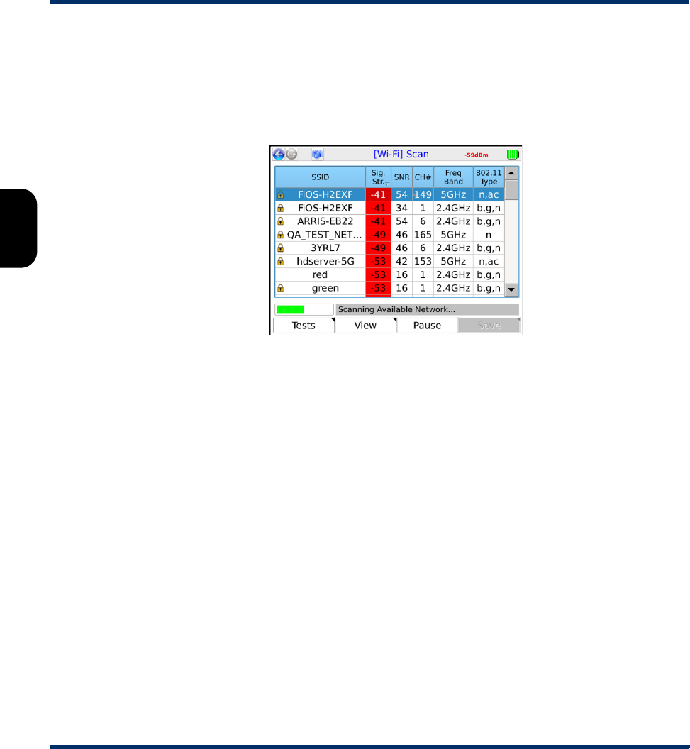
Tech-X Flex User Guide - Firmware v06.50 Tech-X Flex® (NG2)
3-6
Intro Overview Wi-Fi Ethernet System IP/Video MoCA RF Specs
Results - Scan (Wi-Fi Setup)
The scan lists all networks within range of the unit, displaying the SSID (name), an icon that denotes
whether the network is secure (WEP, etc.), and other relevant parameters. The scan reruns periodically
and updates the table. For more information on the fields in the table, see the descriptions under Wi-Fi
Details on page 3-11.
Figure 3-4 Wi-Fi Scan results
Note the following:
• As an option, results may be filtered by geographic region. If you do not see an expected SSID, it
may be due to an applied filter. For more information, see System/Module Settings > Base Unit on
page 5-16.
• A network that does not broadcast its SSID will still be listed, but the SSID value will be blank and the
unit will not allow connection to it.
Results screen shortcuts:
•Tests (F1) - Via a submenu, launches one of:
–Wi-Fi Setup > Connect on page 3-7
–Wi-Fi Analyzer on page 3-10
•SSID Info (F2) - Produces a summary of parameters for the selected network (see Wi-Fi Details on
page 3-11).
•Pause/Resume (F3) - Stops and starts the continuous scan
•Save (F4) - Saves the Scan results (see Record Manager on page 5-1)
Preliminary issue - Limited distribution only!

Tech-X Flex® (NG2) Tech-X Flex User Guide - Firmware v06.50
3-7
Intro
Overview
Wi-Fi
Ethernet
System
IP/Video
MoCA
RF
Specs
3.4.2 Wi-Fi Setup > Connect
The Connect function attempts a connection with a wireless network according to the specified
parameters. If you used the Wi-Fi Setup > Scan function results to launch the Connect, many of the
parameters are automatically populated. For this reason, the Scan function is generally recommended
as a prerequisite.
Once the unit successfully connects, the network parameters are saved in memory under the respective
SSID (name). If you have trouble connecting, see If you cannot connect (troubleshooting tips) on
page 3-4.
Setup - Connect (Wi-Fi Setup)
Table 3-1 Connect (Wi-Fi Setup) - Setup parameters page 1
Parameter Description
SSID (Service Set Identifier) Network name.
Channel Number Network channel, managed automatically by the unit. If the connect request was
initiated from the Scan results screen, it will be populated with the same value from
that screen. Otherwise, it is populated as Auto. In all cases, no user input is
required.
NOTE: Reported channel numbers may deviate from expected values due to
the various methods by which channels are identified. Wi-Fi standards
have concepts of “primary” and “center” channels that represent
different frequencies within the full channel bandwidth. According to their
interpretation of the respective standard, different Wi-Fi devices may
interpret channel numbers differently. A difference between a channel
number configured on another Wi-Fi node and the number reported by
the unit will not affect the ability to connect.
Network Type Type of network:
INFRASTRUCTURE - A centralized network where the unit will negotiate with a
single access point that manages the network overall.
NOTE: Connection to “ad hoc” Wi-Fi networks is currently not supported.
Preliminary issue - Limited distribution only!

Tech-X Flex User Guide - Firmware v06.50 Tech-X Flex® (NG2)
3-8
Intro Overview Wi-Fi Ethernet System IP/Video MoCA RF Specs
Table 3-2 Connect (Wi-Fi Setup) - Setup parameters page 2
Security Type Type of security in use on the network:
•WEP-64 - Wired Equivalent Privacy using a 40-bit key
•WEP-128 - Wired Equivalent Privacy using a 104-bit key
•WPA-PSK or WPA2-PSK - Wi-Fi Protected Access (WPA or WPA2), pre-shared
key mode
•WPA-WPS - Enables the WPS options. The specific WPS option to use should
be specified for Key Type. For more information on WPS, see About WPS
support on page 3-4.
•NONE - No security (open access)
Parameter Description
Key Type and Key Type of key and the key itself, as follows:
•If Security Type=WPA-WPS, see About WPS support on page 3-4 for a
description of options for these fields.
•If Key Type=HEX, the Key must be a hexadecimal number. A hex digit
occupies four bits, so for WEP-64, a hex Key must be 10 digits (40 bits total).
For WEP-128, a hex Key must be 26 digits (104 bits total). For WPA-PSK, the
Key must be 64 digits (256 bits total).
•If Key Type=PASSPHRASE, the key must be the appropriate string that can
be converted to the correct key using the respective algorithms. For WEP-64,
a passphrase Key must be 5 characters/digits. For WEP-128, a passphrase
Key must be 13 characters/digits. For WPA-PSK, a passphrase Key must be
8 to 63 characters.
Also, note that after a successful WPS connection, the unit attempts to store the
underlying WPA authentication for future connection attempts. When successful,
the Key field will show WPS Acquired Key. For more information, see About
WPS support on page 3-4.
Parameter Description
Preliminary issue - Limited distribution only!
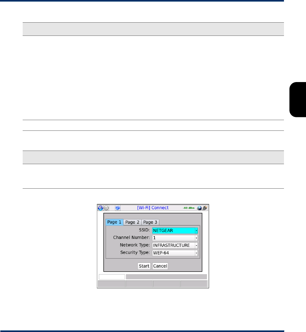
Tech-X Flex® (NG2) Tech-X Flex User Guide - Firmware v06.50
3-9
Intro
Overview
Wi-Fi
Ethernet
System
IP/Video
MoCA
RF
Specs
Table 3-3 Connect (Wi-Fi Setup) - Setup parameters page 3
Figure 3-5 Wi-Fi Connect parameters (Page 1)
WEP Authentication For WEP only, Type of initial authentication used by the wireless access point:
•OPEN - Effectively no authentication to associate and connect; however, all
communications following the connection will be WEP-encrypted and
therefore the unit must still have the correct key specified.
•SHARED - Requires matching keys to establish the initial connection, which
involves a more detailed handshake transaction between the devices.
Afterwards, all communications are WEP-encrypted similar to open
authentication.
NOTE: This setting does not affect how you specify the Key Type and
Key. It controls how the unit attempts initial negotiations only. Both
OPEN and SHARED WEP require a valid key.
WEP Key Slot For WEP only, the slot associated with the specified Key.
Parameter Description
DHCP After
Connect
Causes the unit to attempt a DHCP-based IP network setup if the connection is
successful. Otherwise, IP network setup will be a separate task following the
connection (see IP Testing > IP Network Setup on page 3-18).
Parameter Description
Preliminary issue - Limited distribution only!
Tech-X Flex User Guide - Firmware v06.50 Tech-X Flex® (NG2)
3-10
Intro Overview Wi-Fi Ethernet System IP/Video MoCA RF Specs
Results - Connect (Wi-Fi Setup)
The unit reports whether the connection was successful or not. If the connection is successful, the SYNC
LED lights as solid green. If the connection failed and you don’t know why, see If you cannot connect
(troubleshooting tips) on page 3-4.
While a connection is active, the unit maintains the current signal strength level in the upper right corner:
Additionally, upon a successful connection, the unit proceeds to the Details screen (see Wi-Fi Details on
page 3-11).
NOTE: After connection, you must obtain an IP address if you want to do any IP-based testing, if you
did not request an automatic DHCP request in the connection setup. For more information, see
IP Network Setup on page 6-1.
3.4.3 Wi-Fi Analyzer
The analyzer produces a graphical display of the Wi-Fi channel spectrums within range of the unit. It can
be launched from:
•The Wi-Fi Scan results (see Results - Scan (Wi-Fi Setup) on page 3-6). When launched from this
screen, the analyzer draws a vertical line through the center frequency of the selected channel.
•The Wi-Fi Details screen, following a successful connection (see Wi-Fi Details on page 3-11). When
launched from this screen, the analyzer draws a vertical line through the center frequency of the
connected channel.
The analyzer plots each detected device/SSID within range as a parabolic line, where the height of a plot
indicates the RSSI power level and the width represents the general span of channel usage. The peak of
a plot should generally align with the channel number displayed within other screens; however, variations
may occur depending on bandwidth usage.
The overall frequency range can be set with the Band menu (F1). Additionally, if the Wi-Fi spectrum
feature is licensed, the screen also allows you to set the following with the View menu (F2):
•Spectrum - Toggles a basic overlay of a spectrum power level graph, which updates in real time
similar to the full spectrum display (see Wi-Fi Spectrum Analysis on page 3-17).
•Peak Hold - Toggles an additional peak amplitude graph (see Wi-Fi Spectrum Analysis on
page 3-17).
Preliminary issue - Limited distribution only!
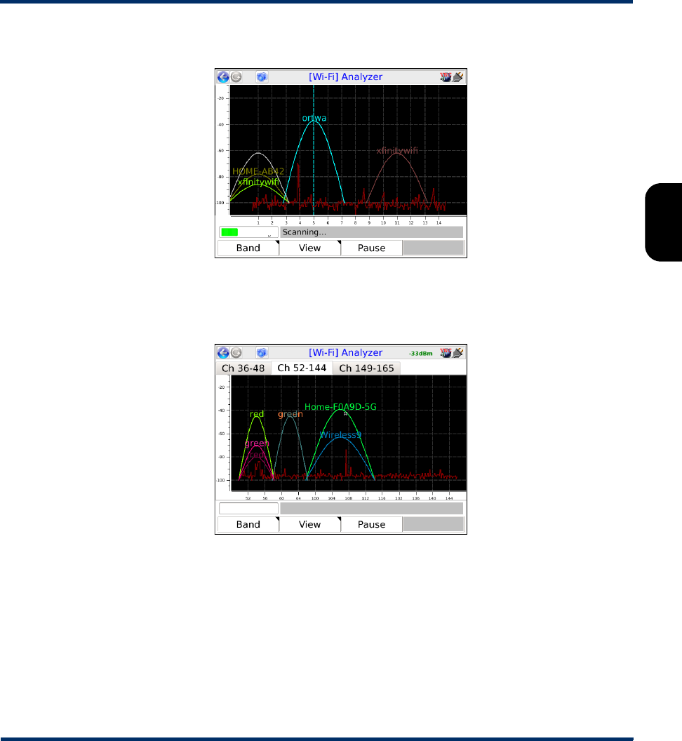
Tech-X Flex® (NG2) Tech-X Flex User Guide - Firmware v06.50
3-11
Intro
Overview
Wi-Fi
Ethernet
System
IP/Video
MoCA
RF
Specs
The following figure shows a sample 2.4 GHz (wireless B and G) analysis:
Figure 3-6 Sample Wi-Fi analyzer screen - 2.4 GHz spectrum
Due to the extent of the 5 GHz spectrum (wireless N and AC), the full graph for this spectrum is spread
over three tabs.
Figure 3-7 Sample Wi-Fi analyzer screen - 5 GHz spectrum
3.5 Wi-Fi Details
The Details function differs according to the area from which it was launched, as follows:
When launched from the Wi-Fi Scan results (Wireless B, G, or N only), the screen shows a basic
table of network parameters, limited to the information available without a connection. See Table 3-4 on
page 3-14 for a description of these parameters.
Preliminary issue - Limited distribution only!
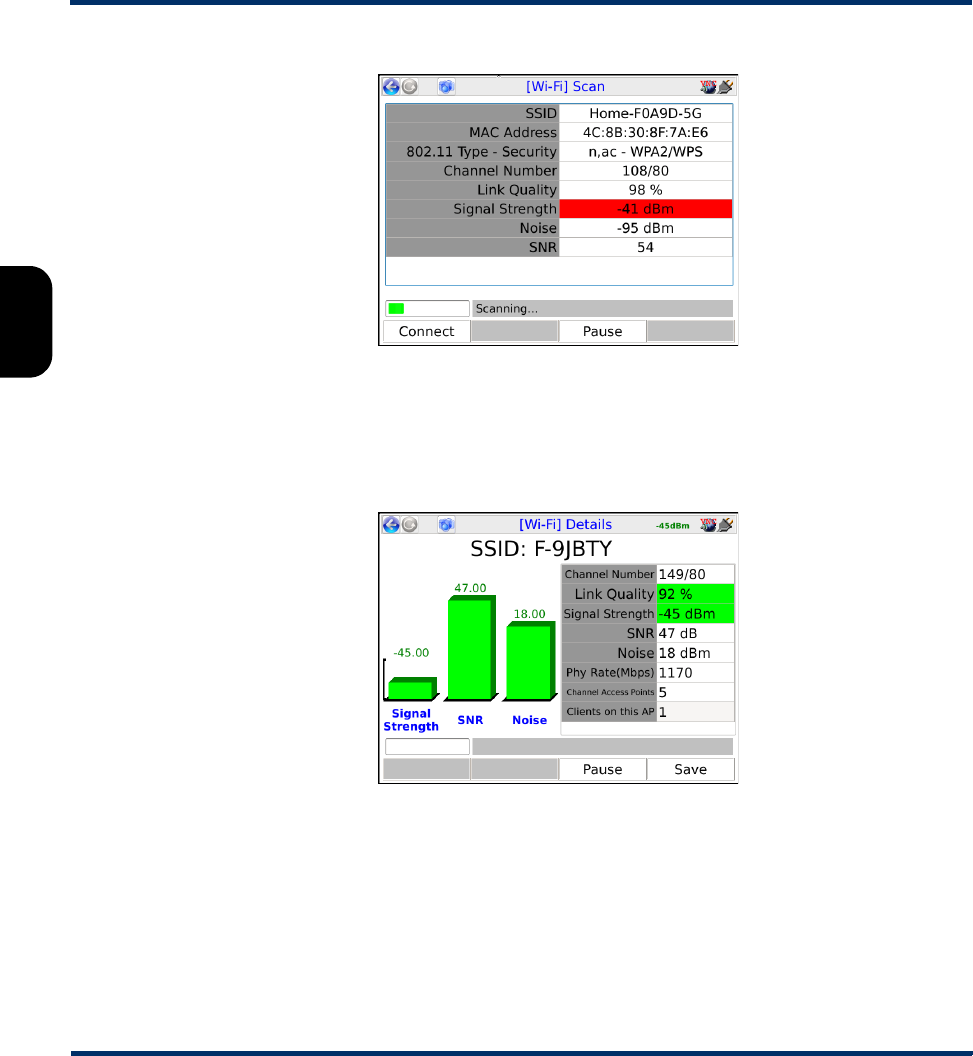
Tech-X Flex User Guide - Firmware v06.50 Tech-X Flex® (NG2)
3-12
Intro Overview Wi-Fi Ethernet System IP/Video MoCA RF Specs
Figure 3-8 Wi-Fi Details screen - Wireless AC connection
When launched from the Details command following a successful Wi-Fi Admin Port connection,
the screen shows similar information in a more graphical format. The screen also includes some
additional information that is only available following the connection. See Table 3-4 on page 3-14 for a
description of these parameters.
Figure 3-9 Wi-Fi Details screen - Wireless AC connection
When launched from the Details command following any other successful connection, the screen
shows the most comprehensive information available, in a mostly graphical format. This information
includes:
Preliminary issue - Limited distribution only!
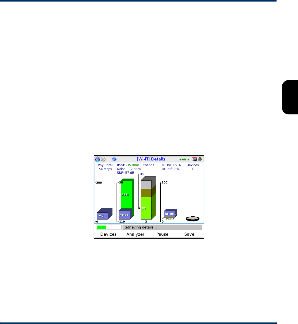
Tech-X Flex® (NG2) Tech-X Flex User Guide - Firmware v06.50
3-13
Intro
Overview
Wi-Fi
Ethernet
System
IP/Video
MoCA
RF
Specs
• Bar graphs for the Phy rate, RSSI, Noise, and SNR (see Table 3-4 on page 3-14). The Phy rate
measurement requires the interface to be configured with IP information.
•A Channel bar graph composed of segments for each detected network/SSID using the current
channel, with the currently-connected SSID segment at the bottom. The total number of SSID
segments in the graph is displayed underneath.The unit attempts to size each segment proportional
to the measured signal strength. Because the graph may represent a compilation of signals, the
overall height of the graph has no functional meaning.
Also, the channel number displays above the graph. For channels in the 5 GHz range, the number
may include a second value; for example, 36/80. The meaning of the second value varies according
to the carrier bandwidth, as follows:
– For an 80 MHz channel, the value is 80; for example, 36/80.
– For a 40 MHz channel, the value is u or i, depending on whether the carrier is in the upper or
lower part of the channel; for example, 36u.
– For a 20 MHz channel, only the channel number appears, for example, 36.
Note that in all cases, this notation may vary from the value reported by the access point or other Wi-
Fi tools, because of inconsistent interpretations by different vendors.
• Graphs showing the RF utilization/interference and Devices for the network (see Table 3-4 on
page 3-14).
Figure 3-10 Wi-Fi Details screen - Wireless AC connection
The screen also provides the following shortcuts:
•Devices (F1) - Displays a table of devices connected to the network, including the unit. For more
information, see Wi-Fi Details > Devices table on page 3-15.
•Analyzer (F2) - Launches the Wi-Fi Analyzer (see Wi-Fi Analyzer on page 3-10).
•Pause/Resume (F3) - Stops/starts the regular refresh of data.
•Save (F4) - Saves the Details results (see Record Manager on page 5-1)
Preliminary issue - Limited distribution only!

Tech-X Flex User Guide - Firmware v06.50 Tech-X Flex® (NG2)
3-14
Intro Overview Wi-Fi Ethernet System IP/Video MoCA RF Specs
The following table describes the Wi-Fi parameters presented in the different screens:
Table 3-4 Details (Wi-Fi Setup) - Results
Result Description
SSID (Service Set Identifier) Network name, as configured in the wireless router.
MAC Address The hardware address of the physical interface at the wireless access point. This
should be a unique identifier of the hardware.
802.11 Type -
Security
The type of Wi-Fi network (b, g, n, or ac) and the type of security implemented, if
any (for example, WPA2).
Channel Number Channel used by the network, typically:
• 1 to 11 for channels in the 2.4 GHz spectrum (Wireless B or G)
• 36 to 165 for channels in the 5 GHz spectrum (Wireless N or AC)
Note that variances are possible based on the country of operation and applicable
regulations. A Wi-Fi connection is based on a single channel which you must have
correctly specified when attempting to connect.
Link Quality General signal quality, as a percentage. This value is based on the measured
signal strength using the following equation, if the signal-to-noise ratio (SNR) is
less than 18:
((<signal_dbm> + 110) / 70) * 100 – (3 * (18 - <snr>))
...otherwise:
((<signal_dbm> + 110) / 70) * 100
...where the value is clipped at 0 or 100 if necessary to remain within the logical 0-
100% range. Note that this value is subjective in nature and provides no positive
indication of whether you can successfully connect, or of the reliability or
throughput following a connection. In many respects, the concept is similar to the
signal strength icons that may appear on other Wi-Fi devices.
Signal Strength Signal power level in dBm.
RSSI (Received Signal Strength Indicator) Overall measured signal power level, in dBm.
Noise Measured noise level, in dBm.
SNR Signal-to-noise ratio of the signal, as the difference between the measured RSSI
and the measured noise.
Preliminary issue - Limited distribution only!

Tech-X Flex® (NG2) Tech-X Flex User Guide - Firmware v06.50
3-15
Intro
Overview
Wi-Fi
Ethernet
System
IP/Video
MoCA
RF
Specs
3.5.1 Wi-Fi Details > Devices table
The Devices table presents a list of devices currently communicating with the same access point on the
connected channel. It is a “best-effort” estimation based on periodic samplings of Wi-Fi packets on the
network. Because the unit cannot monitor all packets continuously, the results are only accurate for the
time periods that it observes. It is possible that connected devices may not appear in the list at all if their
traffic occurs outside of the sampling periods.
All numeric results represent the most recent sampling period only; that is, the unit does not average
previous results. However, a detected device always remains in the table for at least 30 seconds, even if
it is not detected in future samples. When a listed device has no representation in the most recent
sample, all numeric results display as zero (0) because the unit has no data for calculations. Note that
sampling periods correspond with the regular refresh periods of the main Details screen, as all data for
both screens is collected during these times.
The Devices table includes the following columns:
Phy Rate Bit rate of the physical layer bitstream, in Mbps. This value is related to the basic
number of bits that can be transported by the QAM modulation of the analog
waveforms. A stronger signal typically means that QAM symbols can carry more
bits and thus the transport layer data throughput may be higher. Therefore, this
value may provide some indication how well the link can carry digital data.
RF Util
RF Intf
Percentages of time that the channel is occupied with usable wireless packet data
and unusable interference. While measuring, the unit performs a cursory analysis
of all activity on the channel, above a set noise threshold. The utilization rate
represents the percentage of total measurement time that the channel showed
any activity. The interference rate represents a subset of the utilization rate, during
which the channel was occupied with activity that could not be decoded as valid
Wi-Fi traffic (in other words, excessive noise.)
Note that the utilization rate applies to the entire channel and all connected
devices, not just traffic that involves the unit. On any given channel, all devices
must share time using CSMA technology to avoid collisions.
Channel Access
Points
Total number of independent networks/SSIDs broadcasting on the current
channel.
Clients on this AP
-or-
Devices
Estimated total number of hosts connected to the current access point, including
the unit. This count is generated by the same process that populates the Devices
screen and may not be precise. For more information, see Wi-Fi Details > Devices
table on page 3-15.
Result Description
Preliminary issue - Limited distribution only!

Tech-X Flex User Guide - Firmware v06.50 Tech-X Flex® (NG2)
3-16
Intro Overview Wi-Fi Ethernet System IP/Video MoCA RF Specs
Table 3-5 Devices table fields
Result Description
MAC Address Hardware address of the device Wi-Fi interface.
Vendor Device vendor, based on a simple lookup of the MAC address. This lookup uses
an internal table that contains data similar to any publicly-available address
lookup. Therefore, its accuracy cannot be guaranteed.
Possible vendors for a unit include:
• Spirent
• Atheros
• Broadcom
•SparkLAN
RF Util % Estimated total utilization of the entire channel capacity by the respective device.
This value is effectively a “percentage of a percentage,” described in further detail
below.
The Wi-Fi hardware provides an overall channel utilization by all devices, which is
displayed in the main Details screen. Because this circuitry and associated
firmware have direct and constant knowledge of the physical layer bitstream, the
overall utilization remains accurate. For a single device in the Devices screen, the
unit:
• Calculates the percentage of time that the device occupied in the most recent
sample period, effectively a utilization percentage within the sample only.
• Multiplies this calculated percentage against the overall channel utilization to
determine the usage by that device.
For example, if overall channel utilization is 30% and the sampled device
utilization is 10%, the RF Util % is calculated as 3%. That is, the device is using
3% of the total channel capacity.
Note that because this value is partially based on a limited sample period only, its
accuracy cannot be guaranteed.
Captured % The total amount of data sampled with respect to the total amount of data
traversing the channel. Knowledge of the physical layer bitstream allows the unit
to interpolate the total amount of data, even though it did not sample it all. Note
that:
• This value provides a rough indication of how accurate the other calculations
may be.
• Because this calculation applies at the channel level, the value is the same for
all devices, except lingering devices that display all zeros.
Preliminary issue - Limited distribution only!
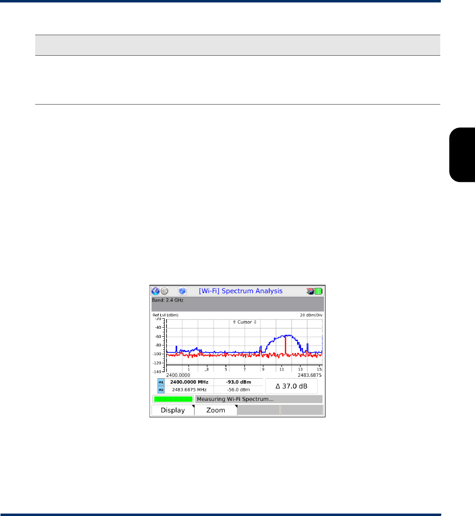
Tech-X Flex® (NG2) Tech-X Flex User Guide - Firmware v06.50
3-17
Intro
Overview
Wi-Fi
Ethernet
System
IP/Video
MoCA
RF
Specs
3.6 Wi-Fi Spectrum Analysis
NOTE: The spectral analyzer is a licensable feature and requires the newer T5300 hardware to
operate. For more information on hardware models, see About hardware models and variations
on page 1-5.
The Wi-Fi Spectrum Analysis tool provides a graph of measured power levels across a set frequency
range within the Wi-Fi spectrum. Its general operation is similar to any common spectral analyzer. In
cases where Wi-Fi quality is poor, the analyzer can help determine whether the spectrum around the
applicable channel has excessive activity and likewise help determine a better channel for connectivity.
The following figure is a sample analysis of the 2.4 GHz band, where the frequencies around channels
10-12 show a significant amount of activity. If connectivity is poor in this channel range, the graph
suggests that a lower channel might be less congested.
Figure 3-11 Sample spectral analysis of the 2.4 GHz range
The Display menu (F1) provides the following commands:
Packet Retries Within the sample for the device, the total number of Wi-Fi packets sent as a
retransmission. Due to the uncertain nature of a wireless connection, each packet
must be acknowledged by the receiver, otherwise a retransmission occurs. The
unit uses the retransmission flag in these packets to produce this count.
Result Description
Preliminary issue - Limited distribution only!

Tech-X Flex User Guide - Firmware v06.50 Tech-X Flex® (NG2)
3-18
Intro Overview Wi-Fi Ethernet System IP/Video MoCA RF Specs
•Running - When toggled, pauses and resumes graph updates.
•Peak Hold - Enables an additional graph that represents the maximum power levels seen at all
points on the spectrum, since the peak hold was activated. To reset the graph, toggle this command.
The blue line on Figure 3-11 is a peak hold plot.
•2.4 GHz and 5 GHz - Toggles the analysis between the two respective spectrum ranges.
•M1 Cursor and M2 Cursor - Toggles the focus on the respective marker. A graph includes two
vertical line markers that may be moved across the graph to update the tables below with specific
values for the respective points. Note that the up/down arrow keys move the active marker, not the
left/right keys.
The Zoom menu allows you to incrementally zoom in to the following frequency spans: 80 MHz, 40 MHz,
and 20 MHz. When zooming in, the center of the graph is established at the active marker (M1 or M2).
3.7 IP Testing > IP Network Setup
This function allows you to assign IP routing information to the unit in order to perform IP-based testing.
This function operates similarly to other interfaces; however, note that when launched from the Wi-Fi
menu, the assigned IP information applies to the wireless interface/connection only.
After a successful setup, the main menu shows an IP Network Disconnect command which will
terminate the IP network connection. If an IP address was obtained via DHCP, it will be released. This
termination will happen automatically if you navigate away from the Wi-Fi menu.
For more information on parameters and results, see IP Network Setup on page 6-1.
NOTE: The unit must have an active wireless connection before this function is available (see Wi-Fi
Setup on page 3-5).
3.8 IP Testing options over Wi-Fi
The Wi-Fi interface provides a suite of IP testing functions that are generally identical to their
counterparts launched from other interfaces. The following table provides links to the central locations in
this document that describe these tests in detail, along with any additional notes that may be relevant to
the Wi-Fi interface.
Preliminary issue - Limited distribution only!

Tech-X Flex® (NG2) Tech-X Flex User Guide - Firmware v06.50
3-19
Intro
Overview
Wi-Fi
Ethernet
System
IP/Video
MoCA
RF
Specs
Table 3-6 IP testing options from the Wi-Fi interface
Test For more information Additional notes
Connection Info Results - IP Network Setup on
page 6-3
This function reports the IP information that is
currently assigned to the 10/100/1G interface
and is identical to the results screen from any
successful IP Network Setup.
Device Discovery All Devices Packet Loss
(Device Discovery) on
page 6-19
The Device Discovery test is the same test
as All Devices Packet Loss, named
differently because its likely purpose is to
discover devices on the current subnet, which
is the initial phase of the All Devices Packet
Loss test. If desired, you can continue with
the packet loss portion of the testing or cancel
the test after the discovery phase.
L4 Performance Test L4 Performance Test on
page 6-7
- - -
Passive Tests Video QoS (Quality of Service)
on page 6-23
- - -
Ping Ping on page 6-4 - - -
Single Device PLT Single Device PLT on
page 6-11
- - -
Speed Test Speedtest on page 6-17 - - -
Traceroute Traceroute on page 6-6 - - -
Web Browser Web Browser on page 6-10 - - -
Preliminary issue - Limited distribution only!

Tech-X Flex User Guide - Firmware v06.50 Tech-X Flex® (NG2)
3-20
Intro Overview Wi-Fi Ethernet System IP/Video MoCA RF Specs
Preliminary issue - Limited distribution only!
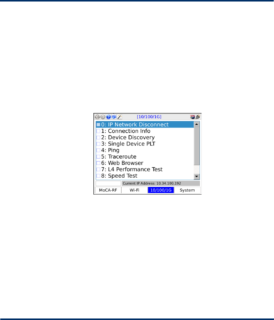
Tech-X Flex® (NG2) Tech-X Flex User Guide - Firmware v06.50
4-1
4: 10/100/1G Testing Menu
With the 10/100/1G testing menu, the unit is able to join a 10/100/1G Ethernet link and run a variety of
functions and tests.
Figure 4-1 10/100/1G main menu
NOTE: On the unit, you can use either 10/100/1G port for single-ended tests such as ping and
traceroute. For more information, see About the 10/100/1G ports and connections on page 4-2.
4.1 Functionality note
Your unit may or may not include all the functionality described in this section, dependent upon your
licensing agreement with Spirent. Please contact Spirent for more information.
Preliminary issue - Limited distribution only!
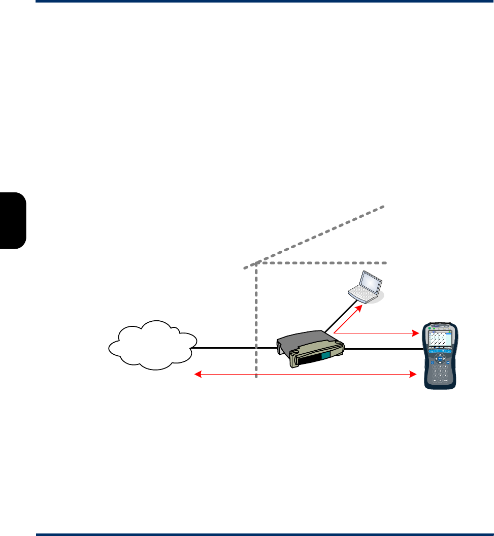
Tech-X Flex User Guide - Firmware v06.50 Tech-X Flex® (NG2)
4-2
Intro Overview Wi-Fi Ethernet System IP/Video MoCA RF Specs
4.2 About the 10/100/1G ports and connections
The unit has two physical 10/100/1G ports which are connected internally by a functional Ethernet
switch. Therefore, when performing single-ended tests such as ping or traceroute, you may use either
port. When setting up an Ethernet bridge for passive tests, the order of the ports is likewise not important.
NOTE: On the physical port, the unit is able to auto-detect the receive and transmit channels; therefore
you may use straight-through or crossover Ethernet cables for any application.
4.3 10/100/1G testing diagram
The following diagram shows a typical setup for active, single-ended tests. For more information on the
setup for bridged, passive testing, see Passive testing on page 4-4.
Figure 4-2 Typical 10/100/1G testing diagram
4.4 IP Network Setup
(10/100/1G > IP Network Setup)
This function allows you to assign IP routing information to the unit in order to perform IP-based testing.
This function operates similarly to other interfaces; however, note that when launched from the
10/100/1G menu, the assigned IP information applies to the 10/100/1G interface/connection only.
Ping, traceroute, web browsing, IPTV video testing
Provider
network/ISP
Home
router
Home
computer
Ping
Preliminary issue - Limited distribution only!

Tech-X Flex® (NG2) Tech-X Flex User Guide - Firmware v06.50
4-3
Intro
Overview
Wi-Fi
Ethernet
System
IP/Video
MoCA
RF
Specs
For more information on parameters and results, see IP Network Setup on page 6-1.
Note the following:
• The unit must be connected to a suitable access device before attempting IP Network Setup (see
10/100/1G testing diagram on page 4-2).
• After a successful setup, the main menu shows an IP Network Disconnect command which will
terminate the IP connection. If an IP address was obtained via DHCP, it will be released. This
termination will happen automatically if you navigate away from the 10/100/1G menu.
4.5 IP testing options over Ethernet
The 10/100/1G interface provides a suite of IP testing functions that are generally identical to their
counterparts launched from other interfaces. The following table provides links to the central locations in
this document that describe these tests in detail, along with any additional notes that may be relevant to
the 10/100/1G interface.
Table 4-1 IP testing options from the 10/100/1G interface
Test For more information Additional notes
Connection Info Results - IP Network Setup on
page 6-3
This function reports the IP information that is
currently assigned to the 10/100/1G interface
and is identical to the results screen from any
successful IP Network Setup.
Device Discovery All Devices Packet Loss
(Device Discovery) on
page 6-19
The Device Discovery test is the same test
as All Devices Packet Loss, named
differently because its likely purpose is to
discover devices on the current subnet, which
is the initial phase of the All Devices Packet
Loss test. If desired, you can continue with
the packet loss portion of the testing or cancel
the test after the discovery phase.
IP Video Tests IP Video testing on page 6-22 - - -
L4 Performance Test L4 Performance Test on
page 6-7
- - -
Packet Capture Packet Capture on page 6-55 - - -
Ping Ping on page 6-4 - - -
Preliminary issue - Limited distribution only!

Tech-X Flex User Guide - Firmware v06.50 Tech-X Flex® (NG2)
4-4
Intro Overview Wi-Fi Ethernet System IP/Video MoCA RF Specs
4.6 Passive testing
NOTE: Passive testing is a purchasable option. Please contact Spirent for more information.
Passive testing allows non-intrusive testing on a bridged Ethernet link. The following sections describe
passive testing and bridge setup in more detail.
4.6.1 Unit setup for passive testing
Because the two 10/100/1G ports are joined internally by a functional Ethernet switch, the unit is
inherently capable of bridging an Ethernet link when placed in the middle. With a bridged link, the unit
can passively monitor traffic between the ports (that is, the traffic flowing across the “bridge”), such as
during a passive measurement of video quality. The ports are always active; therefore, the bridge
capability is always active, with the monitoring feature activated when a passive test is run.
With a passive test, the unit does not send any traffic on the link, nor does it interfere with any traffic
passing through the link. However, an active link will be naturally disrupted when the unit is physically
placed in the middle. For a passive test to run, it is required that the desired traffic is activated or restored
between the bridged endpoints before the testing begins. Using the example of passive video testing,
consider the following typical setup:
Single Device PLT Single Device PLT on
page 6-11
- - -
Speed Test Speedtest on page 6-17 - - -
Traceroute Traceroute on page 6-6 - - -
Video QoS Video QoS (Quality of Service)
on page 6-23
- - -
Web Browser Web Browser on page 6-10 - - -
Test For more information Additional notes
Preliminary issue - Limited distribution only!
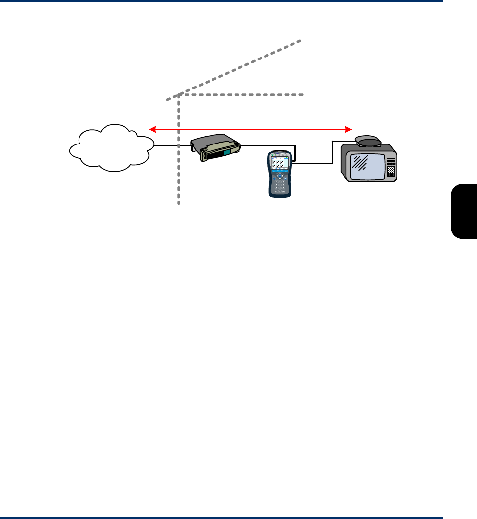
Tech-X Flex® (NG2) Tech-X Flex User Guide - Firmware v06.50
4-5
Intro
Overview
Wi-Fi
Ethernet
System
IP/Video
MoCA
RF
Specs
Figure 4-3 Bridged (passive) video testing
To set up the video test in this example, you should:
1. Connect the physical wires between the endpoints, from router-to-unit and unit-to-STB.
2. Verify that communications between the bridged endpoints are restored. In this example, you should
be able to see the video on the TV.
3. Set up and run the test on the unit.
The following notes apply:
• Following successful IP Network Setup, you can also perform single-ended active tests while the
link is bridged, in either direction. In the previous example, you should be able to ping the STB if you
know its IP address, as well as anywhere upstream, including the internet.
• You can use either crossover or straight-through Ethernet cables for any connections to the unit.
4.6.2 Passive Video QoS (Quality of Service)
(10/100/1G > Passive Tests > Unicast Video QoS)
-or-
(10/100/1G > Passive Tests > Multicast Video QoS > Video QoS)
From a quality analysis standpoint, passive video quality testing is generally identical to active testing,
except that instead of actively joining a video stream, the unit monitors an existing stream on a bridged
Active video stream
ISP / IPTV
video service
Router/
gateway
Set-top box
Passive
monitoring
Ethernet
Preliminary issue - Limited distribution only!

Tech-X Flex User Guide - Firmware v06.50 Tech-X Flex® (NG2)
4-6
Intro Overview Wi-Fi Ethernet System IP/Video MoCA RF Specs
link. Therefore, the video stream must be active between the bridged endpoints before the test can
begin.
For detailed information on the video QoS test parameters and results, see Video QoS (Quality of
Service) on page 6-23.
4.7 Ethernet Cable Test
The Ethernet Cable Test evaluates low-level details about an Ethernet connection and the physical
cable characteristics. It includes TDR capabilities to determine the overall cable length, which may be
useful to detect a short or open on individual pairs.
Note that:
• Some prerequisite knowledge of TDR analysis and Ethernet cable wiring may be required to
understand the results of this test.
• This functionality is driven by native functionality of the onboard Ethernet interface, as an accessory
feature only. It does not involve a dedicated and/or precisely-calibrated test component. Therefore,
the results should be considered general in nature. Furthermore, Spirent firmware can initiate testing
and retrieve results only. It cannot alter the core functionality or accuracy.
4.7.1 Setup - Ethernet Cable Test
The test setup requires the desired physical port to analyze. Refer to the labeling near the 10/100/1G
ports to determine port numbering.
The test may be run on a cable with or without an active signal. With an active signal, the test can
produce a more comprehensive set of results.
Preliminary issue - Limited distribution only!
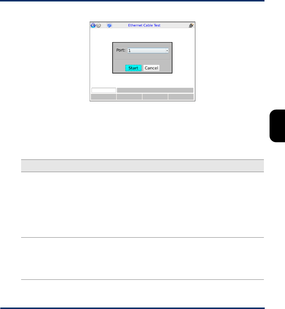
Tech-X Flex® (NG2) Tech-X Flex User Guide - Firmware v06.50
4-7
Intro
Overview
Wi-Fi
Ethernet
System
IP/Video
MoCA
RF
Specs
Figure 4-4 Ethernet Cable Test - Setup
4.7.2 Results - Ethernet Cable Test
The following table describes the full set of possible results. Note that if Ethernet connectivity is not
possible due to a disconnected cable or any other reason, the results contain pair lengths only.
Table 4-2 Ethernet Cable Test - Results
Result Description
Pair Polarity For each MDI pair in a standard cable (4 pairs total out of 8 conductors), indicates
whether the conductors are connected with the proper “polarity,” where:
•Positive - Proper polarity connection
•Negative - Reverse polarity
For each pair, the two pins at each physical port are designated “+” and “-”,
according to Ethernet protocol. With a properly-wired cable, the “+” pin on one end
connects to the “+” pin on the other, and likewise for the “-” pins. Note that although
proper polarity is desired, normally an Ethernet interface can detect a reversed
polarity and internally adjust to allow a connection.
Pair Swap For each pair in the cable, indicates the respective mapping to standard Ethernet
channels (1 or 2 sets of transmit and receive channels). For a properly-wired
straight-through cable, the pairs should map sequentially with channels A through D.
Any other mapping may indicate an improperly-wired cable. It is possible that
improper wiring can support 10/100 Mbps but not 1 Gbps Ethernet, because 1 Gbps
requires all four pairs instead of the two used by 10/100 Mbps.
Preliminary issue - Limited distribution only!

Tech-X Flex User Guide - Firmware v06.50 Tech-X Flex® (NG2)
4-8
Intro Overview Wi-Fi Ethernet System IP/Video MoCA RF Specs
Pair Skew For each pair, the difference in signal propagation time; that is, the time required for
an electrical signal to traverse the respective loop. Ideally, all pairs associated with a
common signal should have identical or very close propagation times, because a
large skew can disrupt high-bandwidth signals with a low tolerance for timing
variations. The primary causes of skew include differing conductor lengths due to
inconsistent twist ratios and differing insulation types.
The skew results are presented in nanoseconds (ns) and are relative to the pair with
the shortest propagation time. The pair with the shortest time shows a skew of zero
(0), while the skew of each other pair represents the additional length of time
required for its respective propagation.
Industry practice varies with regard to the maximum amount of skew that is
acceptable. Additionally, the type of signal, length of cable, and other factors
influence that determination. For these reasons, it is beyond the scope of this
document to provide recommendations on acceptable skew values.
Cable Len For each pair, the estimated 1-way cable length based on a TDR trace. This value
normally indicates the end of the pair, or possibly the first short or open. Note that:
• The maximum measurable cable length is approximately 656 ft. (200 meters).
• At a minimum, the accuracy may deviate by +/-7 ft. (+/-2 meters).
Cable Test
Result
For each pair, a general pass/fail recommendation based on the following two TDR-
related analyses:
•Maximum Peak Check - The TDR trace is analyzed for the highest interim
“peak,” where a peak is analogous to an upward rise in a standard graphical TDR
result. A peak typically occurs when the TDR pulse encounters a point of high
impedance, causing a larger reflection. Internally, the unit applies a threshold to
determine the amplitude necessary to indicate an unacceptable peak.
•First Peak Check - Similar to the maximum peak, the unit sets a different
threshold to determine the first unacceptable peak in the trace. Note that the first
peak is usually the same as the maximum peak, but may differ.
For each case on each pair, if the respective interim peak is not detected, the test
assumes a proper termination of the pair and reports a status of “pass.” Otherwise,
the test reports the approximate location of the associated impedance change with
suggestions of the possible cause.
Result Description
Preliminary issue - Limited distribution only!
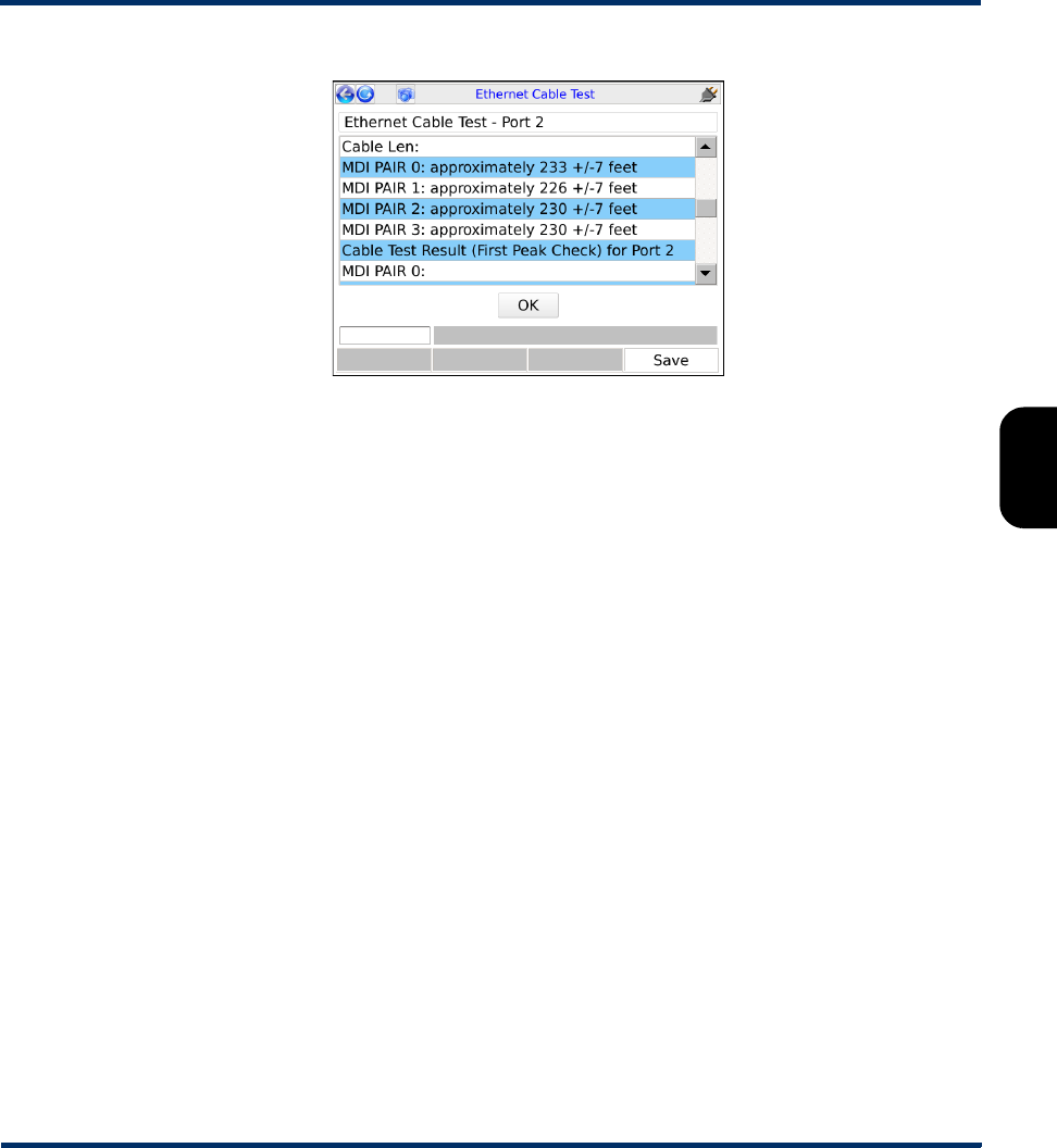
Tech-X Flex® (NG2) Tech-X Flex User Guide - Firmware v06.50
4-9
Intro
Overview
Wi-Fi
Ethernet
System
IP/Video
MoCA
RF
Specs
Figure 4-5 Ethernet Cable Test - Results, showing cable lengths
Preliminary issue - Limited distribution only!

Tech-X Flex User Guide - Firmware v06.50 Tech-X Flex® (NG2)
4-10
Intro Overview Wi-Fi Ethernet System IP/Video MoCA RF Specs
Preliminary issue - Limited distribution only!
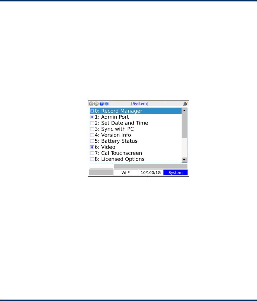
Tech-X Flex® (NG2) Tech-X Flex User Guide - Firmware v06.50
5-1
5: System Menu
The System menu provides access to general system configuration.
Figure 5-1 System main menu
5.1 Record Manager
(System > Record Manager)
The Record Manager is used to manage, view, and transfer record files, which are special files used to
store test results, screen captures, and other related data. When you invoke the Save function in a
results screen, they are saved to a record file. For non-continuous, self-terminating tests, the full results
set is saved at the end of testing. For continuous tests, you can control when saving is active, during
which time a full results set is saved following the end of each reporting interval.
For test results, at any given time a single record file is considered the active file, which is presented as
the default when you manually initiate a Save action in a test results screen (see Saving results on
page 2-29). If you have never created any record files, the unit uses a “DEFAULT” record file until you
Preliminary issue - Limited distribution only!

Tech-X Flex User Guide - Firmware v06.50 Tech-X Flex® (NG2)
5-2
Intro Overview Wi-Fi Ethernet System IP/Video MoCA RF Specs
specify otherwise. If you do not have the need for multiple record files, the default record may be
sufficient for general use.
For screen capture files, each capture is stored in a separate file that is named at the time of the capture.
For more information, see Capturing a screen image (screenshot) on page 2-28).
NOTE: All files in the Record Manager remain on the unit until purposefully deleted. A unit shutdown
will not delete record data.
The unit has no specific maximum number of record files or maximum amount of results that any record
can contain. However, it does have a certain overall limit related to the constraints of physical memory. A
general rule which might be useful is to have no more than 30 general record files on the unit at once,
each with no more than 20 sets of test results. The actual numbers can vary, though, especially
considering the type of results you are saving. For example, the results data set from a video test is many
times larger than a ping test. Additionally, the presence of screen capture files can reduce the space
available for test results.
The following sections describe the individual Record Manager functions in more detail:
•Record Manager > Test Result Files on page 5-2 - Provides a viewer for test result files, along with
file management tools
•Record Manager > Signature Cap Files on page 5-3 - Reserved for future use
•Record Manager > Screen Capture Files on page 5-4 - Provides tools to view and/or delete screen
capture files
•Record Manager > Upload Files on page 5-4 - Provides tools for transferring Record Manager files
from the unit to a remote computer, including test result and screen capture files
5.1.1 Record Manager > Test Result Files
This function allows you to view and manage files currently on the unit. The actions that may be invoked
by the respective function key include:
Table 5-1 Record Manager functions
Function Description
New Creates a new record file. The name can have any alphanumeric name, often reflecting a
work order number or a customer location.
NOTE: Do not begin a record name with a period (N1 key), otherwise it will not
appear in the Record Manager.
Preliminary issue - Limited distribution only!
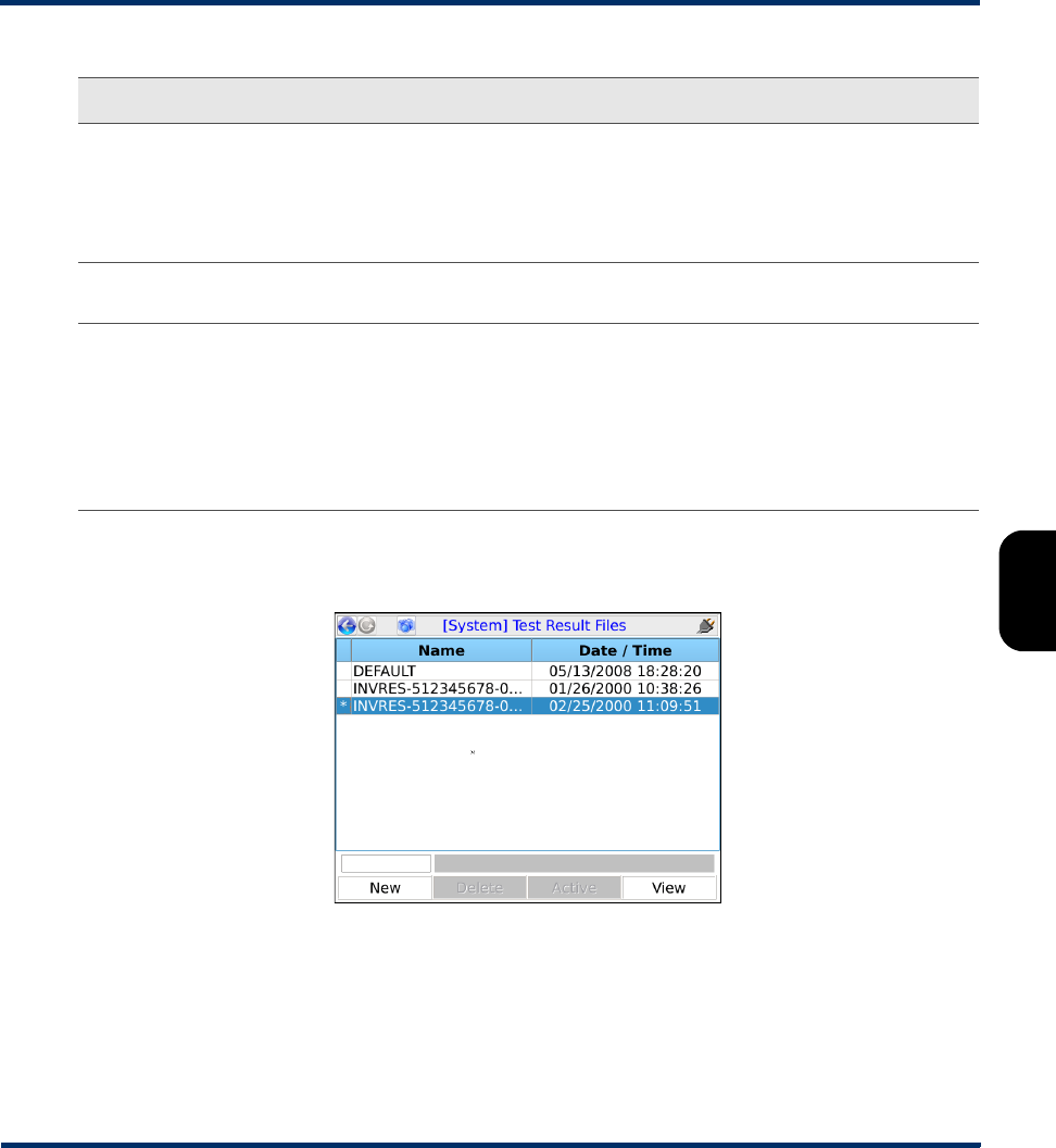
Tech-X Flex® (NG2) Tech-X Flex User Guide - Firmware v06.50
5-3
Intro
Overview
Wi-Fi
Ethernet
System
IP/Video
MoCA
RF
Specs
NOTE: The currently-active file is shown with an asterisk (*) in the left column.
Figure 5-2 Record Manager > Test Result Files
5.1.2 Record Manager > Signature Cap Files
Reserved for future use.
Delete Deletes the selected file. This action cannot be undone.
NOTE: Files that begin with INVRES (INVentory/RESults) are normally generated by
testing that saves results automatically. They contain a broad scope of
information that is designed for incorporation by a custom, back-office
management system. For more information, please contact Spirent.
Active Makes the selected file the active file, which then appears as the default when a Save
action is initiated in a test results screen.
View Opens the selected file for viewing in the form of a tree view of results. Normally, a results
set includes one branch with shows details on the original test setup, with a second branch
indicating the success or failure of the operation with additional details as applicable.
NOTE: For some tests, a “mode” parameter appears in the setup area, such as
mode:POLLED and mode:NEXT. The “polled” mode indicates the first interval
of a repeating test and the “next” mode applies to all subsequent intervals of the
respective test. In many cases, this parameter can be simply ignored.
Function Description
Preliminary issue - Limited distribution only!

Tech-X Flex User Guide - Firmware v06.50 Tech-X Flex® (NG2)
5-4
Intro Overview Wi-Fi Ethernet System IP/Video MoCA RF Specs
5.1.3 Record Manager > Screen Capture Files
This area allows you to preview and/or delete screen capture files currently stored in the Record
Manager (see Capturing a screen image (screenshot) on page 2-28). To upload screen capture files to a
remote computer, see Record Manager > Upload Files on page 5-4.
5.1.4 Record Manager > Upload Files
This function allows you to transfer record files from the unit to a remote computer, using one of the
following:
•FTP - Using one of the interfaces such as the Admin Port, files are transferred to a running FTP
server on a remote computer.
NOTE: FTP server setup is a separate task. For more information, see FTP information on
page 2-57.
•USB - Using the physical USB port on the unit, allows the files to be transferred to a USB storage
device such as a removable flash drive, then transferred from that device to a computer.
NOTE: Do not plug the unit directly into a computer.
At the bottom of the screen, the Start button initiates the transfer. The following table describes the
parameters in the various tabs that should be reviewed carefully before you click Start:
Table 5-2 Record Manager > Upload Files parameters
Tab Description
Destination
tab
Defines the method for the transfer:
•FTP - Requires FTP connection parameters for the remote FTP server. For more
information, see FTP connection parameters on page 2-59.
•USB - Requires a USB storage device, such as a removable flash drive, to be
physically connected to the unit. FTP connection parameters are not applicable.
Source tab For FTP only, defines the interface from which the FTP connection will be attempted. If
the interface is not currently configured with routable IP information, this tab also
provides fields for that information. When the transfer action is initiated, the unit will
attempt to configure the selected interface first.
Files tab Used to select the specific files that should be transferred and whether they should be
deleted from the unit following a successful transfer. Note that the list in this area
includes both test result files and screen capture files, as applicable.
Preliminary issue - Limited distribution only!
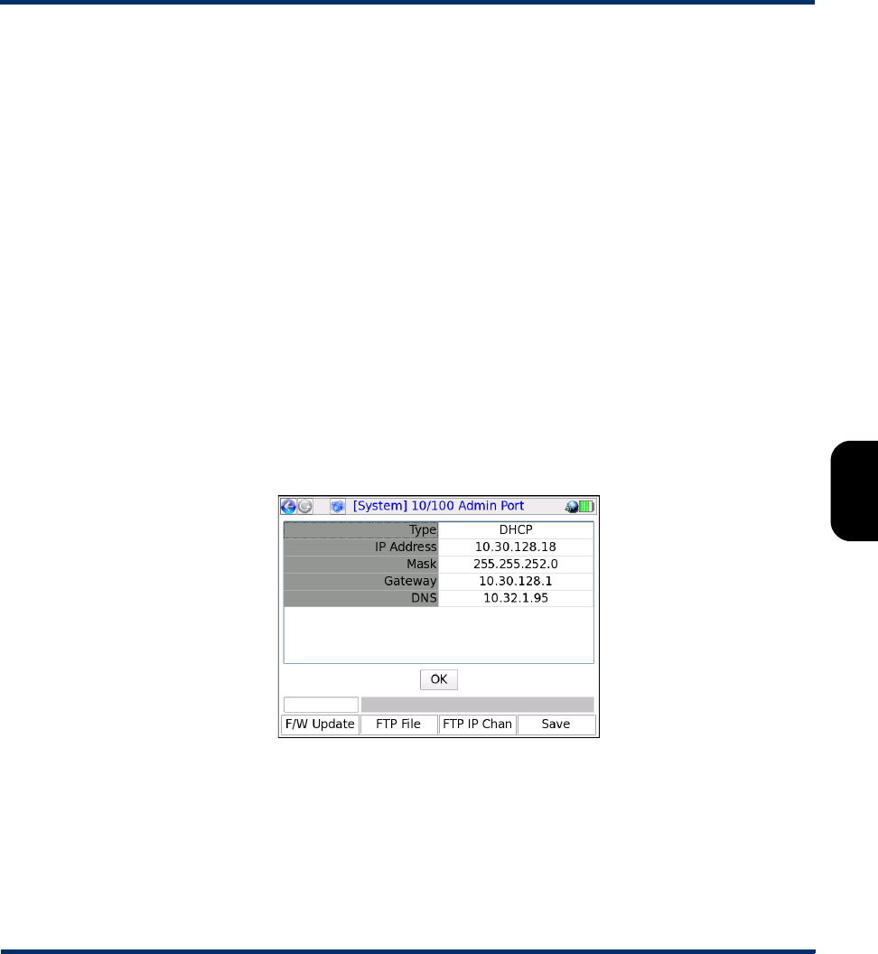
Tech-X Flex® (NG2) Tech-X Flex User Guide - Firmware v06.50
5-5
Intro
Overview
Wi-Fi
Ethernet
System
IP/Video
MoCA
RF
Specs
5.2 Admin Port
(System > Admin Port)
This function assigns IP data to the internal management interface of the unit, a prerequisite connection
step for management activities such as firmware upgrades and other actions requiring an FTP exchange.
In this document, all activities that require an Admin Port connection are specifically indicated as such.
Note that this function does not provide general access to the operating system of the unit.
The Admin Port can be connected via two different interfaces, the choice of which is shown in the initial
Admin Port screen:
•10/100/1G Admin Port - Initiates a connection through the 10/100/1G Ethernet interface. Either
physical 10/100/1G connector may be used. Once in this area, the process of establishing a
connection is very similar to establishing a 10/100/1G connection for testing purposes with the
10/100/1G menu. For more information on behavior and parameters, see IP Network Setup on
page 4-2.
•Wi-Fi Admin Port - Initiates a connection through the Wi-Fi interface. Once in this area, the process
of establishing a connection is very similar to establishing a Wi-Fi connection for testing purposes
with the Wi-Fi menu. Note that all considerations and limitations involved with a test-related Wi-Fi
connection also apply to the Wi-Fi Admin Port. For more information on behavior and parameters,
see Wi-Fi Setup on page 3-5.
Figure 5-3 Admin Port results screen following a successful connection
Once an admin port is established, you can view the IP address and other connection info at any time
under System > Admin Port > Connection Info. The information presented is similar to the connection
parameters available from any IP setup (see Connection Info on page 6-4).
Additionally, this area includes two additional commands related to remote control of the unit (see
Remote control of the unit on page 2-33):
Preliminary issue - Limited distribution only!

Tech-X Flex User Guide - Firmware v06.50 Tech-X Flex® (NG2)
5-6
Intro Overview Wi-Fi Ethernet System IP/Video MoCA RF Specs
•System > Admin Port > WAN Remote Control - See Remote site remote control (via the internet)
setup on page 2-46.
•System > Admin Port > Wi-Fi Admin Port > AP Remote Control - See Local remote control (via a
Wi-Fi access point) setup on page 2-45.
Upon a successful Admin Port connection, the results screen includes shortcuts to the following:
•F/W Update (Firmware update - see Update Firmware on page 5-13)
•FTP File (Record manager file upload - see Record Manager > Upload Files on page 5-4)
•FTP IP Chan (IPTV channel guide download - see Download IPTV Channel Guide on page 5-8)
In all cases, when a shortcut is launched, any applicable information from the Admin Port configuration
is automatically transferred to the respective setup screen.
Note the following important items:
• In some situations, an active Admin Port may conflict with Ethernet/IP traffic on other interfaces,
especially if multiple interfaces are attempting to host traffic on the same subnet. For example, if you
are attempting to host IP traffic over a MoCA interface while you have an active 10/100/1G Admin
Port with the same router, issues may occur depending on the type of router. If any particular
scenario exhibits trouble, please contact Spirent for a feasibility analysis.
•An active 10/100/1G Admin Port is known to prevent proper functionality of the Bridge (ECB) mode
feature of the MoCA Module.
5.3 Set Date and Time
(System > Set Date and Time)
The date and time are used to timestamp all saved results in the Record Manager. They are also used
for various internal functions, described in this document elsewhere as appropriate.
The date and time must be entered using the following formats:
•Date - yyyy-mm-dd
•Time - hh:mm:ss
To set the date or time, select either parameter and press a number on the keypad to initiate the numeric
entry screen. You must enter all characters that are requested, using leading zeros as necessary to pad
empty spaces. For example:
09:10:00
Preliminary issue - Limited distribution only!
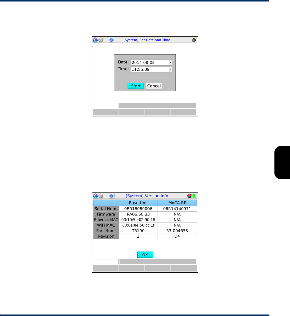
Tech-X Flex® (NG2) Tech-X Flex User Guide - Firmware v06.50
5-7
Intro
Overview
Wi-Fi
Ethernet
System
IP/Video
MoCA
RF
Specs
...would set the time to 9:10 a.m. Note that the unit uses 24 hour time. For example, 9:10 p.m. would be
set as 21:10:00.
Figure 5-4 Set Date and Time screen
5.4 Version Info
(System > Version Info)
This function provides information about hardware and firmware versions currently applicable to the unit,
including the attached module, if any. This information may be required when obtaining technical support
from Spirent. It may also be useful for verification before and/or after firmware upgrades.
Figure 5-5 Version Info
Preliminary issue - Limited distribution only!

Tech-X Flex User Guide - Firmware v06.50 Tech-X Flex® (NG2)
5-8
Intro Overview Wi-Fi Ethernet System IP/Video MoCA RF Specs
5.5 Battery Status
(System > Battery Status)
This function provides detailed information about the battery and current charging conditions. Note the
following:
• The charging information in this screen may not be accurate if the battery is overheated. For more
information, see Important battery charging note on page 2-22.
• The temperature may be displayed in degrees Fahrenheit or Celsius, according to system settings
(see System/Module Settings > Base Unit on page 5-16).
5.6 Video
This area contains various functions and settings related to video testing.
5.6.1 Download IPTV Channel Guide
(System > Download IPTV Channel Guide)
This function is used to transfer video testing channel guide files to the unit using FTP. To transfer files,
you must have:
• A supported FTP server running on a networked computer. For more information, see FTP server
installation and setup on page 2-58.
• The channel guide files in a folder on that networked computer in the proper location (see File
preparation and general handling notes on page 5-9).
• The unit connected to a 10/100/1G Ethernet network that can reach the FTP server computer.
Once these steps are complete, the download may be initiated. For more information, see Download
procedure on page 5-9. For general information about channel guide functionality, see About channel
guides on page 6-53.
NOTE: A working knowledge of FTP is helpful for server setup and successful file transfer.
Preliminary issue - Limited distribution only!

Tech-X Flex® (NG2) Tech-X Flex User Guide - Firmware v06.50
5-9
Intro
Overview
Wi-Fi
Ethernet
System
IP/Video
MoCA
RF
Specs
File preparation and general handling notes
• Every transfer action deletes all existing channel guides from the unit, even if the server folder does
not contain any valid files to replace them.
• On the FTP server computer, the files to transfer must be placed in the “home directory” associated
with the FTP user account that you intend to use. For any given transfer action, only the files in a
single folder are transferred to the unit.
• Channel guides must be in the proper XML format as described under About channel guides on
page 6-53.
• All files with an *.xml extension (case-insensitive) are transferred. Any other files in the designated
folder are ignored.
NOTE: If a file named thresholds.xml exists (case-insensitive), it will also be ignored. For this
reason, a channel guide file cannot use this name.
• Other than general limitations of internal disk space, the unit has no functional limitation on how many
channel guide files it may contain.
Download procedure
1. Connect the unit to a 10/100/1G Ethernet network that can access the computer running the FTP
server.
2. Select System > Download Channel Guide and specify the required parameters for download. If
you do not have a Admin Port currently set up, these parameters information must include Admin
Port configuration information. For more information, see FTP connection parameters on page 2-59.
5.6.2 Video > View/Edit Thresholds
This screen allows you to view thresholds that affect the coloring/shading of results for certain Video
QoS test results (VQM version, see Video QoS (Quality of Service) on page 6-23). Currently-supported
results include the “percent degradation” due to loss, jitter, codec type, and delay.
Thresholds are specified as ranges, where a result will be colored:
•Red, if the metric falls outside the specified range
•Green, if the metric falls within the specified range, inclusive
Along with ranges, each threshold can be individually enabled or disabled. If a threshold is disabled, the
corresponding result receives no coloring regardless of its value.
Additionally, note the following:
Preliminary issue - Limited distribution only!
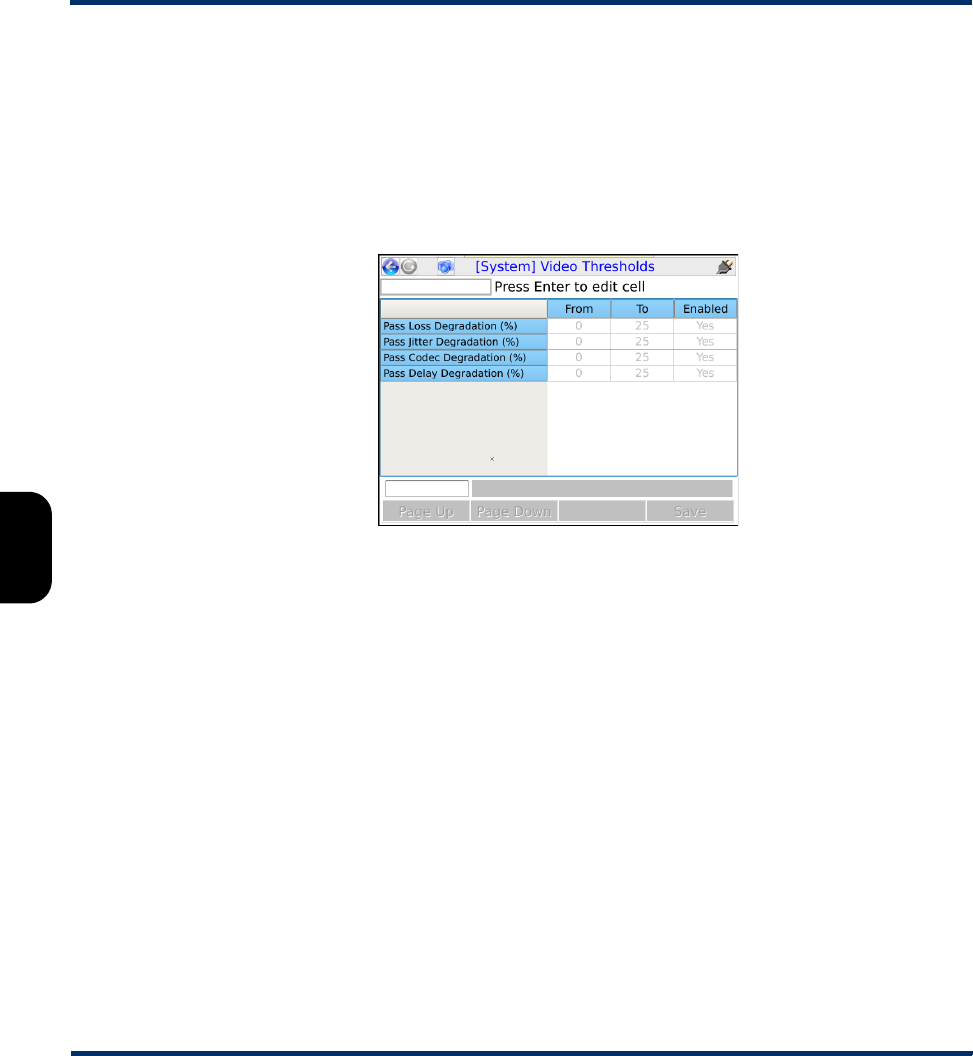
Tech-X Flex User Guide - Firmware v06.50 Tech-X Flex® (NG2)
5-10
Intro Overview Wi-Fi Ethernet System IP/Video MoCA RF Specs
• When specifying thresholds, the unit enforces theoretical/technical limitations. For example, a
percentage cannot be less than zero or greater than 100. In general, if the inherent lower or upper
range of a threshold represents a technical limit, the unit restricts the editing of the field altogether.
• For results that are represented as a percentage, where an increasing percentage normally indicates
a worsening condition, the unit will enforce zero as the lower range limit.
As an example, with the following setup, any related percentage would be colored red if measured
greater than 25%:
Figure 5-6 Video Thresholds screen
5.6.3 Video > Download Thresholds
This function allows you to download a thresholds file to set all video thresholds as a batch. This action
completely overwrites all existing thresholds on the unit.
For more information on the parameters required for the FTP transaction, see FTP connection
parameters on page 2-59. The remainder of this section describes the required threshold file format.
A threshold file uses a simple CSV format with lines in the following syntax:
thld_name,from_value,to_value,enabled
For example:
Pass Loss Degradation (%),--,25,Yes
It must have the following filename:
VideoThresholds.dat
Note the following:
Preliminary issue - Limited distribution only!
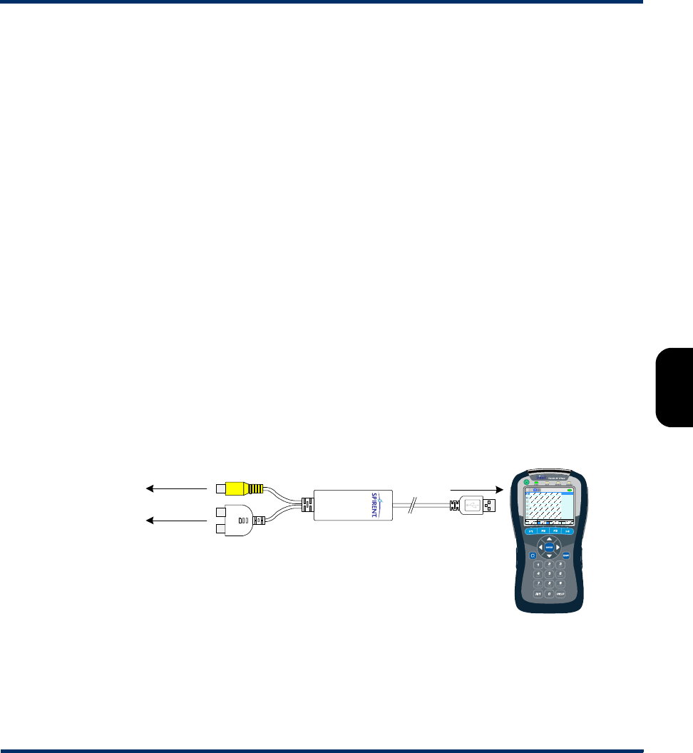
Tech-X Flex® (NG2) Tech-X Flex User Guide - Firmware v06.50
5-11
Intro
Overview
Wi-Fi
Ethernet
System
IP/Video
MoCA
RF
Specs
• The best way to prepare a threshold file is to start with a working sample. Contact Spirent to obtain a
sample.
• You should never change a threshold name (first field), otherwise the threshold will become
unrecognizable and the unit will use a default instead.
• If any value exceeds a theoretical limitation, the unit will reset it to a valid value. For example, if a
percentage value exceeds 100, it will be reset to 100 upon import. For fields that inherently require a
theoretical minimum or maximum, you can specify two hyphens (--) instead of an explicit value.
• You can precede any line with an exclamation point (!) to restrict the setting from editing onboard the
unit, for example:
!Pass Loss Degradation (%),--,25,Yes
In this case, the threshold range will be viewable on the unit, but will not be editable. Note that this
condition cannot be undone except by importing another thresholds file to the unit.
5.6.4 Video > Video Monitor
The Video Monitor feature allows the unit to serve as a basic video display monitor, similar to a
television that is connected to an STB. The primary purpose of this feature is to allow video and STB
verification in the absence of an actual television; however, it may also be used for any situation where a
monitor is required for an analog video feed.
Using a required dongle, the unit accepts a simple analog video signal as provided by tuning devices
such as STBs, DVD players, etc. The dongle must be ordered from Spirent and should be connected as
follows:
Figure 5-7 Video Monitor dongle connection
With the dongle properly connected and a video signal active, the video should begin to display as soon
as you select Video Monitor. Note the following:
USB in
To STB video out
(yellow)
To STB audio out
(red and white)
Preliminary issue - Limited distribution only!

Tech-X Flex User Guide - Firmware v06.50 Tech-X Flex® (NG2)
5-12
Intro Overview Wi-Fi Ethernet System IP/Video MoCA RF Specs
• The unit has no tuning or decoding capabilities. A simple signal feed from a “video out” source is
required.
•The ENTER key on the physical keypad toggles the zoom on and off. When the zoom is on, the arrow
keys allow navigation around the screen.
• The video may lag slightly as compared to a normal television.
• The audio connection is optional. Additionally, certain internal hardware is required for the unit to play
audio, which may not be present in some older units. Please contact Spirent for more information.
• An external VNC viewer cannot render the video and will show a blank screen while the Video
Monitor is active.
5.7 Cal Touchscreen
(System > Cal Touchscreen)
This function calibrates the touchscreen display for optimal response. Calibration should be done after
firmware upgrades, after battery replacement, or if the screen response begins to degrade after heavy
use.
The process requires you to touch the screen in several places with a stylus or other approved device.
Follow the instructions on the screen.
5.8 Licensed Options
(System > Licensed Options)
This function reports which optional features are currently enabled for the base unit and modules (if any),
which may be required when seeking technical support. It also allows you to manually enable features by
entering valid key codes, which is may be required to enable licensed features on a new unit. To enter a
key code, press Update Key (F1) and enter the key exactly as provided by Spirent. Note the following:
• For more information on what the individual licenses do, see Licensed feature details on page 2-53.
• Firmware upgrades include a provision to automatically apply licensing codes if properly configured
in a file and located on the server from which the firmware is retrieved. For more information, see
Update Firmware on page 5-13.
• The unit requires a unique key code for each licensed feature. For example, to enable both the web
browser and IP video testing, you need to enter two different codes.
• For manual code entry, you do not need to enter anything except the code itself. The unit will
recognize the feature to which it applies and then list that feature as enabled.
Preliminary issue - Limited distribution only!

Tech-X Flex® (NG2) Tech-X Flex User Guide - Firmware v06.50
5-13
Intro
Overview
Wi-Fi
Ethernet
System
IP/Video
MoCA
RF
Specs
• A key code is specific to a unit and will not work on any other unit.
• Key codes must be provided by Spirent. In some cases, the codes required for your licensed feature
set are shipped in the package with the unit. If you have trouble with the codes or require new codes
for any reason, please contact Spirent.
5.9 Update Firmware
(System > Update Firmware)
This function initiates the unit firmware upgrade process. The firmware package must reside on a remote
computer with a properly-configured rsync server running and with IP-level connectivity to the unit.
Spirent hosts one such rsync server which may be available for your use, dependent upon your
arrangement with Spirent and preferences as an organization. Alternatively, you may set up your own
server for private, internal use. The remaining information in this section (including Table 5-3, Update
Firmware parameters on page 5-14) assumes the use of the Spirent-hosted server. For more information
on setting up your own server, please contact Spirent for additional documentation.
Before an update may be initiated, you must configure an Admin Port with connectivity to the rsync
server (see Admin Port on page 5-5). Additionally, note the following:
• The unit should not be powered down or lose network connectivity during the update process. For
this reason:
–The use of a 10/100 (versus Wi-Fi) Admin Port is recommended. If you do use a Wi-Fi
connection, it is highly recommended that you connect with Wireless G or higher, as Wireless B
may not be stable enough to reliably handle the volume of firmware data.
– The unit requires external power to be connected before allowing an update.
If an update is interrupted, in most cases you should be able to restart the unit and at least
attempt the update again. However, there is a very short window during the process when an
interruption will render the unit unusable and require it to be returned for repair. For this
reason, all precautions against an interruption are highly recommended.
• Firmware may be updated at any time, especially if you are using the Spirent-hosted server. Regular
updates help ensure that your unit is performing at its peak capacity. Note that you can view the
current firmware version on the unit with the Version Info function (see Version Info on page 5-7).
• You do not need to connect a specific module or any module at all to run a firmware upgrade. All
firmware is installed on the base unit, which then transfers it to modules as necessary. If a
disconnected module component is affected by an upgrade (such as the ADSL/VDSL2 module
modem, which has its own firmware), the unit will warn you and then proceed to upgrade that
component when the module is reconnected.
The Update Firmware setup screen includes the following parameters:
Preliminary issue - Limited distribution only!

Tech-X Flex User Guide - Firmware v06.50 Tech-X Flex® (NG2)
5-14
Intro Overview Wi-Fi Ethernet System IP/Video MoCA RF Specs
NOTE: The middle column indicates the values to use if you are updating from the Spirent-hosted
server. All values should be considered case-sensitive.
Table 5-3 Update Firmware parameters
Parameter Value to use for the
Spirent-hosted server Additional description
Server SPIRENT If you are not using the Spirent-hosted server, this must be
the IP address or domain name of the computer where the
rsync server and firmware files reside. The unit is
provisioned to recognize the SPIRENT keyword to
automatically reach the Spirent server.
Firmware latest This is an alias that designates the desired firmware
package to install, normally latest when using the Spirent-
hosted server unless you have been instructed otherwise.
Aliases must be preconfigured on the server computer in
a specific fashion, which is a topic addressed in the
additional documentation available for custom rsync
server setup.
License File TXH_LICENSE_KEYS The name of the file on the server that contains licensing
information for the unit you are upgrading. Licensing is
always updated during the upgrade process unless one or
more of the following are true, in which case licensing
remains in its original state:
• The file is missing or set up incorrectly
• The unit cannot find its licensing information in the file
For custom rsync server setup, additional documentation
from Spirent is available on the management of this file.
Update
License Only
No This setting specifies whether to do a licensing update
only and skip the firmware upgrade. In most cases, the
two are done concurrently.
Ping Before
Download
Yes (recommended) Indicates whether to perform a ping test to the designated
Server before attempting the upgrade. If the ping fails, the
upgrade action will abort.
Timeout 15 Indicates a maximum amount of time to allow for the
upgrade process, after which it is aborted. An aborted
process leaves the unit in its original functional state.
Preliminary issue - Limited distribution only!
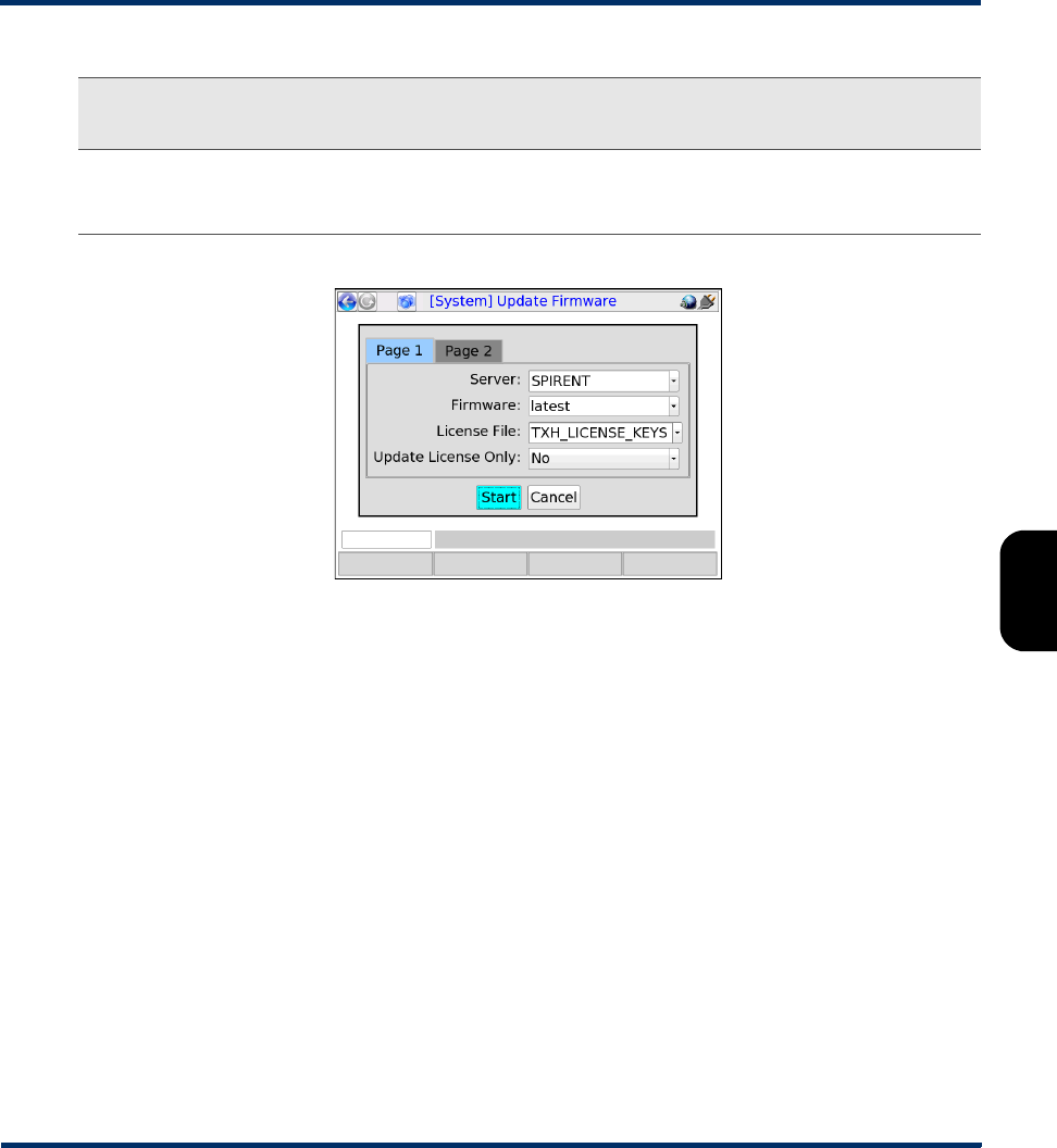
Tech-X Flex® (NG2) Tech-X Flex User Guide - Firmware v06.50
5-15
Intro
Overview
Wi-Fi
Ethernet
System
IP/Video
MoCA
RF
Specs
Figure 5-8 Setup for use of the Spirent-hosted server
5.10 System/Module Settings
(System > System/Module Settings)
This function is used to configure the base unit and/or the attached module and its behavior varies
according to the type of module attached, if any. This section describes the base unit parameters only.
For more information on module settings, see the respective module documentation.
User
Password
(leave blank) Authentication information for the rsync server, configured
when the server is set up. The Spirent-hosted server does
not require authentication.
Parameter Value to use for the
Spirent-hosted server Additional description
Preliminary issue - Limited distribution only!
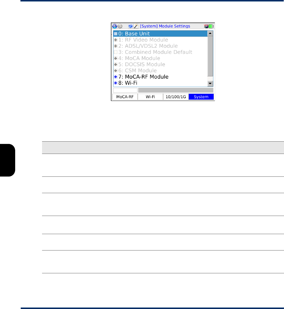
Tech-X Flex User Guide - Firmware v06.50 Tech-X Flex® (NG2)
5-16
Intro Overview Wi-Fi Ethernet System IP/Video MoCA RF Specs
Figure 5-9 Module Settings menu
5.10.1 System/Module Settings > Base Unit
Table 5-4 Base Unit settings
Tab Description
Auto Power Off Sets the maximum amount of idle time after which the unit automatically shuts
down to save battery power. This setting has no effect when the unit is connected
to external power.
Primary Keyboard Selects the default keypad that appears when text entry is initiated. For more
information, see Running a function or test on page 2-24.
Imperial/Metric Selects the global measurement system for the unit, affecting display items such
as the battery temperature, Fahrenheit vs. Celsius (see Battery Status on
page 5-8).
First Name
Last Name
General user information, contained in all results files saved to the Record
Manager.
ID Number A general purpose ID that can be assigned to the unit. This ID is contained in all
results files saved to the Record Manager.
Speed Test Region Default region to use for the Speed Test, including a test launched by any “quick
test” or similar script. Normally, this value may be changed in the respective setup
screen.
Preliminary issue - Limited distribution only!

Tech-X Flex® (NG2) Tech-X Flex User Guide - Firmware v06.50
5-17
Intro
Overview
Wi-Fi
Ethernet
System
IP/Video
MoCA
RF
Specs
5.10.2 System/Module Settings > RF Video Module
See System menu settings/controls (for RF) on page 8-22.
5.10.3 System/Module Settings > ADSL/VDSL2 Module
See the ADSL/VDSL2 Modem Module User Guide.
5.10.4 System/Module Settings > Combined Module Default
Reserved for future use.
5.10.5 System/Module Settings > MoCA Module
See System menu settings/controls (for MoCA) on page 7-27.
5.10.6 System/Module Settings > DOCSIS Module
See the DOCSIS Module User Guide.
WiFi Region Optional filter for Wi-Fi channel tuning. If set to any value other than
International, the unit filters SSIDs during a Wi-Fi Scan according to the valid
spectrum available at the specified region. In other words, the Scan results will
omit any SSIDs that do not fall within the valid spectrum.
Spectral consideration and filtering are based on common industry standards. For
additional explanation of international spectrum usage, visit
https://en.wikipedia.org/wiki/List_of_WLAN_channels.
RF Bandwidth For RF module testing, the expected bandwidth of channels, either 6 MHz or 8
MHz. Channel bandwidth varies in different countries.
If WiFi Region=International, you can set this value manually. Otherwise, it is set
automatically based on the configured WiFi Region.
Tab Description
Preliminary issue - Limited distribution only!

Tech-X Flex User Guide - Firmware v06.50 Tech-X Flex® (NG2)
5-18
Intro Overview Wi-Fi Ethernet System IP/Video MoCA RF Specs
5.10.7 System/Module Settings > CSM Module
See the Cable Services Module User Guide.
5.10.8 System/Module Settings > MoCA-RF Module
See:
•System menu settings/controls (for MoCA) on page 7-27
•System menu settings/controls (for RF) on page 8-22
5.10.9 System/Module Settings > Wi-Fi
These settings are currently not used.
5.11 Signature Capture
This feature allows you to capture a signature using the unit touchscreen. It is generally reserved for
future use.
NOTE: This feature will not function correctly when operating the unit over remote control, even if the
remote device has a touchscreen.
5.12 Language Selection
This function allows you to set the language used by the unit. Note the following:
• Language support is limited. Please contact Spirent for more information.
• On the unit, a language is represented by a special file that contains all the strings associated with
that language. Optionally, you can download another language file to the unit, either to add a new
language or update an existing language. This functionality is recommended for advanced users
only, because the management of language files is complex with many considerations. For more
information, please contact Spirent.
5.13 Help and Support
Launches the onboard help system, similar to pressing Help on the physical keypad.
Preliminary issue - Limited distribution only!

Tech-X Flex® (NG2) Tech-X Flex User Guide - Firmware v06.50
5-19
Intro
Overview
Wi-Fi
Ethernet
System
IP/Video
MoCA
RF
Specs
5.14 System Information
This function provides basic information on current disk space usage. If the available disk space falls
below 10%, the unit will start deleting result files automatically, oldest files first. File deletion occurs
silently during unit shutdown.
5.15 Wizard GUI
Closes the “classic” view and launches the workflow interface. For more information, see Introduction to
the workflow interface on page 2-1.
Preliminary issue - Limited distribution only!

Tech-X Flex User Guide - Firmware v06.50 Tech-X Flex® (NG2)
5-20
Intro Overview Wi-Fi Ethernet System IP/Video MoCA RF Specs
Preliminary issue - Limited distribution only!