Spirent Communications FLEX-T5300 Tech-X Flex (NG2) User Manual Tech X Flex Manual
Spirent Communications Inc Tech-X Flex (NG2) Tech X Flex Manual
Contents
- 1. User Manual Part 1
- 2. User Manual Part 2
User Manual Part 2

Tech-X Flex® (NG2) Tech-X Flex User Guide - Firmware v06.50
6-1
6: IP and Video Testing
This section describes the suite of IP and video (IPTV) functions available on the unit. These tests are
available over various interfaces on the unit, including the Wi-Fi and Ethernet interfaces, and modular
interfaces such as MoCA. Not all tests are available for all interfaces; see the respective documentation
for specific testing support.
Once an interface is correctly configured with routable IP information, testing from that interface should
be generally identical to any other. For example, ping testing from the Wi-Fi interface should be identical
to ping testing from the Ethernet interface, except that it is launched from a different menu. Therefore, the
information is consolidated here and applies generally to any interface that supports the respective test.
To configure an interface with routable IP information, use the IP Network Setup function (see IP Network
Setup on page 6-1). Once setup is successful, the IP testing becomes available, depending upon unit
licensing and the test support of the respective interface:
NOTE: Your unit may or may not include all the functionality described in this section, dependent upon
your licensing agreement with Spirent. Contact an account manager for more information.
6.1 IP Network Setup
This function is used to configure the active interface as necessary to join an IP network. For example, if
you are using the 10/100/1G menu, this function configures the 10/100/1G interface with the IP routing
information required to send and receive IP traffic. For any interface, IP Network Setup is a required
prerequisite to any test that sends and/or receives IP data over that interface.
IP Network Setup must be performed each time the unit is started up, for the interface(s) that you intend
to use. Furthermore, you may need to run the setup again after switching test menus, if the menu change
activates a different interface on the unit. To facilitate frequent setup actions, the unit supports DHCP,
which is the preferred method of configuration if a DHCP server is available. By using DHCP, you can
more easily assure that valid IP routing information is assigned which does not conflict with any other
host on the network.
Preliminary issue - Limited distribution only!

Tech-X Flex User Guide - Firmware v06.50 Tech-X Flex® (NG2)
6-2
Intro Overview Wi-Fi Ethernet System IP/Video MoCA RF Specs
Before attempting IP Network Setup, the unit must be linked up with the proper access device,
according to interface type. For example, if you are performing 10/100/1G testing, the unit should be
connected to a switch or router with an Ethernet cable. Or, for Wi-Fi testing, the unit should be within
range and synchronized with an active Wi-Fi node.
Note the following:
• For DHCP, If you change the active interface, the unit will attempt to release the IP address from the
DHCP server. For example, if you obtain an IP address through the Wi-Fi menu, then switch to the
10/100/1G menu, the IP address will be released.
• If you disconnect the unit and reconnect it to another network, you should rerun the network setup. IP
information for one network may not be routable on another.
6.1.1 Setup - IP Network Setup
Table 6-1 IP Network Setup - Setup parameters
Parameter Description
Type Method for assigning IP information:
•Static - Static assignment. If you select this method, the unit will request the
static address information.
•DHCP - DHCP assignment. If a DHCP server is available, all IP information is
assigned automatically. DHCP is a common method for IP address
assignment within a home network and most home network routers include a
DHCP server.
NOTE: If the unit fails to get an address with DHCP, see Results - IP
Network Setup on page 6-3.
Option 60
(DHCP only)
Class identifier, used for the “option 60” field of the DHCP request as defined by
RFC 1533. The class identifier may be used to send vendor or site-specific
information for use by the DHCP server. If this field is not specified, no value is
sent.
NOTE: Dependent upon licensing, the dropdown list may include one or
more commonly-used IDs.
VLAN ID
(Certain interfaces
only)
802.1ad VLAN tag for all transmitted Ethernet frames, from 1 to 4094. If
unspecified, all transmitted frames are untagged. Note that:
• This specification must match the requirements of the connected network; for
example, a far-end port that is expecting a certain tag is likely to reject any
traffic from the unit that is untagged, and vice-versa.
• Some IP interfaces, such as the Admin Port, do not support VLAN tagging. In
this case, the VLAN ID field does not appear.
Preliminary issue - Limited distribution only!

Tech-X Flex® (NG2) Tech-X Flex User Guide - Firmware v06.50
6-3
Intro
Overview
Wi-Fi
Ethernet
System
IP/Video
MoCA
RF
Specs
If you select static assignment, the unit requires you to manually enter the IP address, subnet mask,
default gateway, and DNS server. The unit will accept any information that you specify and attempt to use
it for active test traffic, whether it is routable or not. Therefore, you should be sure to enter valid
information, otherwise subsequent IP-based testing will fail. In addition, note the following:
• Ensure that you have specified generally valid IP information. For example, the unit cannot assign an
address of 0.0.0.0 because it is not valid for IP communications.
• For static assignment, the DNS server address is optional. However, if you do not specify a valid
server, you must know the target IP address for any IP-based tests. That is, the unit will be unable to
resolve domain names such as www.spirent.com.
6.1.2 Results - IP Network Setup
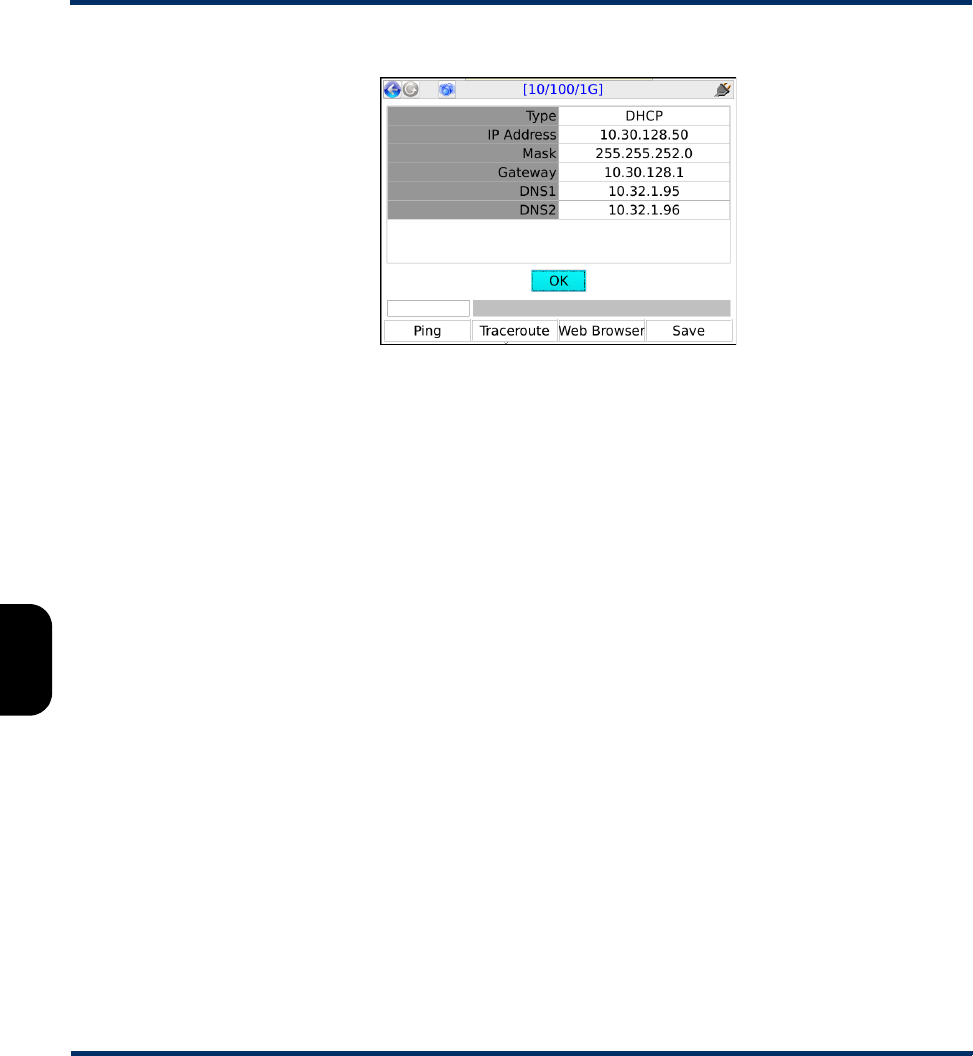
The results screen displays either the assigned IP information, or a failure message if the process failed.
Fields include:
Table 6-2 IP Network Setup - Results
VLAN Priority
(Certain interfaces
only)
If a VLAN ID is specified, the priority to assign with the tag.
Parameter Description
Result Description
Type Method used for address assignment, such as DHCP.
IP Address
Mask
Gateway
IP information assigned to the respective interface.
DNS1
DNS2
DNS address(es) assigned to the interface, for URL lookup. DNS2 only applies
to DHCP transactions where the server returns a second DNS address. In any
other case, this field shows N/A.
Preliminary issue - Limited distribution only!
Tech-X Flex User Guide - Firmware v06.50 Tech-X Flex® (NG2)
6-4
Intro Overview Wi-Fi Ethernet System IP/Video MoCA RF Specs
Figure 6-1 Successful IP Network Setup
6.1.3 DHCP troubleshooting tips
If a DHCP operation fails, check the following:
• The unit is properly connected to an active, networked device. For example, when using the
10/100/1G interface, the Ethernet cable must be properly connected. Or, for the Wi-Fi interface, the
unit must be within range of an active wireless node.
• The target network has an active DHCP server. In a home network, the DHCP server is normally
incorporated with the home router, in which case you may need to log into the router to ensure that
the DHCP server has not been disabled. See the router documentation for more information.
6.2 Connection Info
This function reports the IP information that is currently assigned to the active interface and is identical to
the results screen from a successful IP Network Setup. For more information, see Results - IP Network
Setup on page 6-3.
6.3 Ping
IP Ping is a basic connectivity test that verifies whether a specific IP address can be reached. It sends a
set of ICMP echo requests to an IP address and reports whether replies are successfully received. The
request is sent via the active interface of the unit and requires that routable IP information is assigned to
that interface. For more information, see IP Network Setup on page 6-1.
Preliminary issue - Limited distribution only!

Tech-X Flex® (NG2) Tech-X Flex User Guide - Firmware v06.50
6-5
Intro
Overview
Wi-Fi
Ethernet
System
IP/Video
MoCA
RF
Specs
6.3.1 Setup - Ping
Table 6-3 Ping - Setup parameters
6.3.2 Results - Ping
Along with details about each individual ping request, the unit also reports the following summary
information:
Table 6-4 Ping - Results
Figure 6-2 Successful Ping results
Parameter Description
Destination Target address for the ping request, either a dotted IP address or a URL if a DNS
is available. For example:
208.22.58.142
www.google.com
Result Description
Packets Sent Number of ping requests sent to the address
Packets Received Number of ping requests reported as successfully received
Packets Lost Percentage of ping requests that were lost (Packets Sent - Packets
Received)
Approximate round trip
time in milliseconds
Average time for a ping requests to reach its destination and then for the
unit to receive the success report
Preliminary issue - Limited distribution only!
Tech-X Flex User Guide - Firmware v06.50 Tech-X Flex® (NG2)
6-6
Intro Overview Wi-Fi Ethernet System IP/Video MoCA RF Specs
6.4 Traceroute
Provides a standard ICMP or UDP traceroute function that runs three concurrent traceroute processes
and reports every router “hop” along the path, up to 30 hops. The results provide a topological view of the
route that packets are using to reach the destination.
The request is sent via the active interface and requires that routable IP information is assigned to that
interface. For more information, see IP Network Setup on page 6-1.
6.4.1 Setup - Traceroute test
Table 6-5 Traceroute - Setup parameters
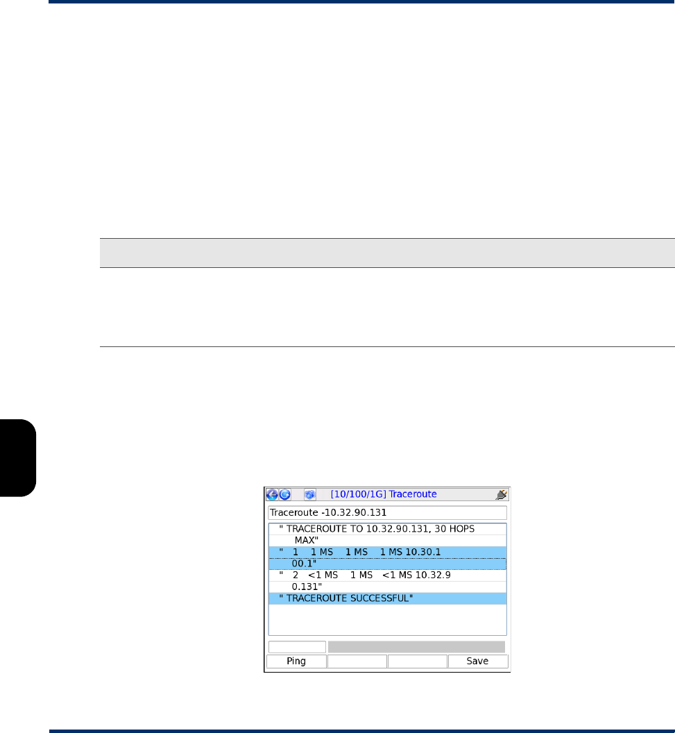
6.4.2 Results - Traceroute test
The unit reports the IP address of each sequential hop along the path to the target, along with the
roundtrip time required for each hop to receive the probe packet and the unit to receive acknowledgment.
Because three independent traceroute processes are run, three topology sets are presented. An asterisk
appears if a time cannot be determined, such as a response timeout when a router cannot or will not
return a response.
Figure 6-3 Successful Traceroute results
Parameters Description
Destination Target address for the traceroute request, either a dotted IP address or a URL if
a DNS is available. For example:
208.22.58.142
www.google.com
Preliminary issue - Limited distribution only!

Tech-X Flex® (NG2) Tech-X Flex User Guide - Firmware v06.50
6-7
Intro
Overview
Wi-Fi
Ethernet
System
IP/Video
MoCA
RF
Specs
6.5 L4 Performance Test
The L4 Performance Test is useful to verify the availability of a certain bandwidth and to determine the
maximum overall throughput. According to the test setup, it can run in either the upstream or
downstream direction.
The test uses iPerf 3.1 as the underlying technology, based in layer 4 (TCP or UDP). Therefore, the
target endpoint must be a compliant iPerf 3.1 server. The unit first establishes a “control plane”
connection with the server over TCP, then negotiates the testing setup. When primary testing begins,
either the unit or the server initiates the requested number of streams to the other endpoint. Both
endpoints analyze the traffic and maintain an identical set of results metrics. Once the primary testing is
complete, the endpoints exchange results information and then terminate all connections.
iPerf 3.1 is principally developed and maintained by third-party Energy Sciences Network (ESNet) /
Lawrence Berkeley National Laboratory. For more information on ESNet and iPerf, visit
http://software.es.net/iperf/.
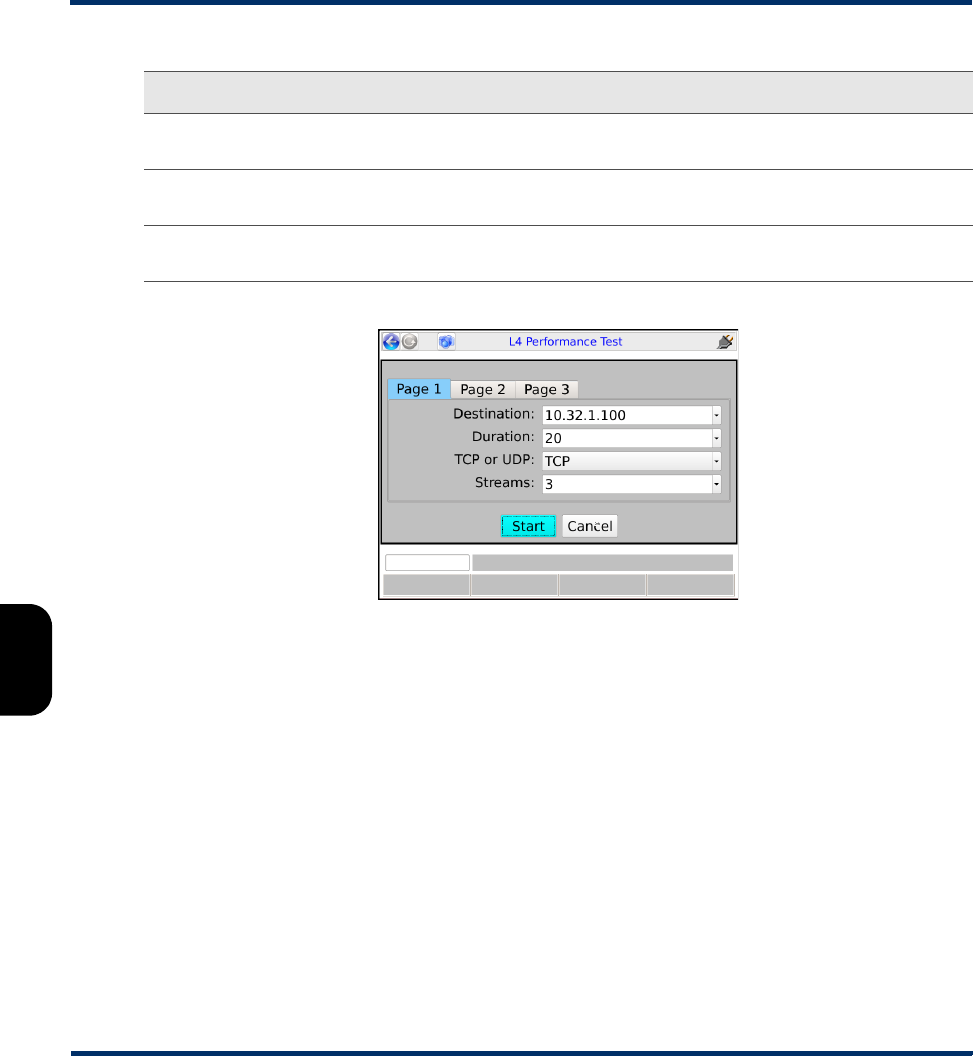
6.5.1 Setup - L4 Performance Test
Table 6-6 L4 Performance Test - Setup
Parameter Description
Destination IP address or URL of the target iPerf server.
Duration Length of time to run the primary testing segment, in seconds.
TCP or UDP Specifies whether to use TCP or UDP encapsulation for the primary test
streams. Typically, TCP is the preferred option.
Streams Number of parallel TCP or UDP streams to initiate and maintain during
the primary testing segment. For a downstream test, traffic streams are
initiated by the server and received by the client, each stream on a unique
destination port. For an upstream test, the unit initiates the streams, each
on a unique source port.
Port TCP port on which the server listens for client communications. All activity
regarding the server occurs on this port; including all control plane
negotiations and test stream activity.
BW Maximum throughput to attempt, in Mbps. For TCP tests only, you can
specify 0 (zero) to test at the maximum throughput possible.
TCP Win Sz
(TCP tests only)
Window size to configure on the TCP interface of each endpoint, in bytes.
Specify 0 (zero) to allow the interfaces to negotiate and use a size based
on default interface settings.
Preliminary issue - Limited distribution only!
Tech-X Flex User Guide - Firmware v06.50 Tech-X Flex® (NG2)
6-8
Intro Overview Wi-Fi Ethernet System IP/Video MoCA RF Specs
Figure 6-4 L4 Performance Test - Setup
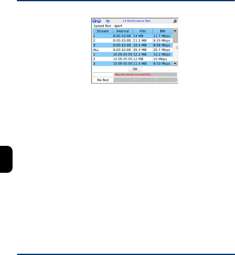
6.5.2 Results - L4 Performance Test
The following table describes the basic metrics produced by the test, noting the following behavior:
• If the test is set up to produce interval results, a full set of results is produced for each interval,
independently for each stream. Additionally, each interval produces a full set of results that reflects
the composite of all streams.
• At the end of the results, the test produces a similar of group of results that reflect the entire testing
period. These results are produced from the perspective of the sender and from the receiver, if
available. For example, a 2-stream test might produce the following rows:
–S1 - Whole-test averages/totals for stream 1, from the perspective of the sender interface.
–R1 - Whole-test averages/totals for stream 1, from the perspective of the receiver interface.
–S2 and R2 - Whole test results for stream 2.
–S_ALL and R_ALL - Whole test results for all streams combined.
Report Interval Interval at which to report interim results, in seconds. Specify 0 (zero) to
produce composite results at the end of the test only.
Direction Test direction; that is, the direction of traffic flow, either Upstream or
Downstream.
Omit Number of initial seconds to exclude from results calculations, normally
used to avoid the impact of the normal TCP slow start algorithm.
Parameter Description
Preliminary issue - Limited distribution only!

Tech-X Flex® (NG2) Tech-X Flex User Guide - Firmware v06.50
6-9
Intro
Overview
Wi-Fi
Ethernet
System
IP/Video
MoCA
RF
Specs
Note that In some cases, “S” and/or “R” results are not available and do not display. In most cases,
server compatibility is the cause.
Table 6-7 L4 Performance Test - Results
Result Description
Stream Stream number for the respective row, or ALL to indicate a composite of
all streams.
Interval Test interval for which the results apply, displayed in seconds. Results
that apply to the entire test show an interval that spans from zero to the
test duration.
Xfer Total amount of TCP or UDP payload data transferred during the interval,
in MB.
BW Average bandwidth seen during the interval, in Mbps.
Retr
(TCP upstream test only)
Amount of data that required retransmission, in bytes.
CWND
(TCP upstream test only)
Congestion window size at the end of the interval in bytes, as maintained
by the sender.
Pkts
(UDP test only)
Total number of packets transmitted during the interval
Jitter
(UDP download test only)
Average jitter measured during the interval, in msec.
Lost
(UDP test only)
Total number of packets that did not reach the destination.
Preliminary issue - Limited distribution only!
Tech-X Flex User Guide - Firmware v06.50 Tech-X Flex® (NG2)
6-10
Intro Overview Wi-Fi Ethernet System IP/Video MoCA RF Specs
Figure 6-5 L4 Performance Test - Results (Downstream TCP Test)
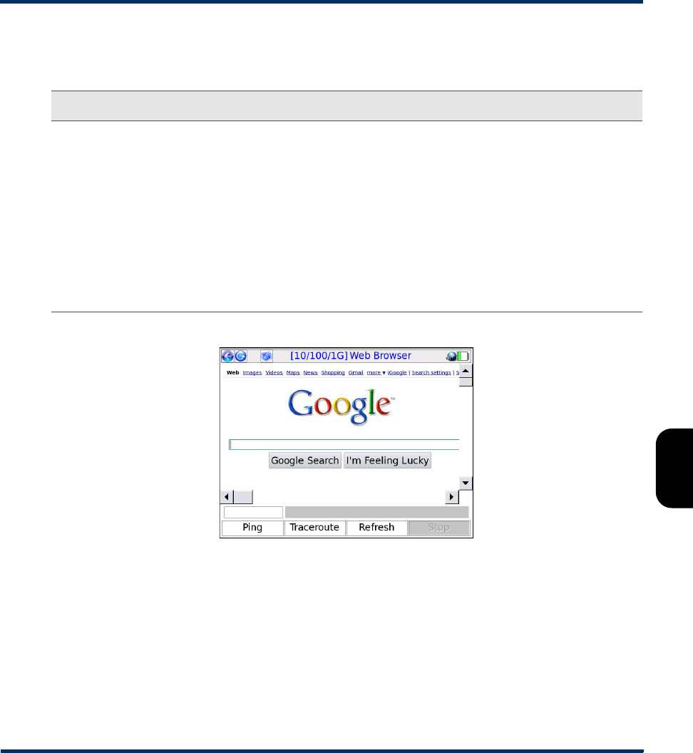
6.6 Web Browser
NOTE: The web browser is a purchasable option. Please contact Spirent for more information.
The Web Browser allows you to access web pages from the internet and view them on the screen. It
may be especially useful for verifying that internet access is available, beyond a simple ping test. If a
residential subscriber cannot view a web page but you can with the unit, you can normally conclude that
the trouble exists with the subscriber’s web browser, computer, or home network configuration. It may
also be used to verify that a DNS is available.
The Web Browser is similar to a browser used on a desktop computer, except that the smaller screen
may require more use of the scroll bars. Furthermore, aside from basic hyperlinks, most webpage
controls may not work correctly. In some cases, complex pages with extensive internal scripting may not
display correctly or at all, so it is recommended that you use simple, fast-loading web pages to perform
tests. In summary, the browser is intended as a testing tool, not as a fully-functional interface to the
internet.
To access the Web Browser, the active interface must be configured with valid, routable IP information.
For more information, see IP Network Setup on page 6-1.
Preliminary issue - Limited distribution only!
Tech-X Flex® (NG2) Tech-X Flex User Guide - Firmware v06.50
6-11
Intro
Overview
Wi-Fi
Ethernet
System
IP/Video
MoCA
RF
Specs
6.6.1 Setup - Web Browser
Table 6-8 Web Browser - Setup parameters
Figure 6-6 Web Browser, showing the Google™ website
6.7 Single Device PLT
The Single Device PLT (Packet Loss Test) runs a continuous series of ping tests to a single destination,
maintaining and presenting a set of cumulative results as testing progresses. These results include the
number of lost ping packets since the beginning of the test.
NOTE: This test is a purchasable option. Please contact Spirent for more information.
Parameters Description
URL Target address of the web page to load, either a dotted IP address or a URL if a
DNS is available. For example:
208.22.58.142
www.google.com
Note the following:
• When entering a URL, case is unimportant because all characters are
converted to lower case when the browser is launched.
• The unit remembers the recent addresses you entered.
• The dropdown list may automatically include one or more commonly-used
websites.
Preliminary issue - Limited distribution only!
Tech-X Flex User Guide - Firmware v06.50 Tech-X Flex® (NG2)
6-12
Intro Overview Wi-Fi Ethernet System IP/Video MoCA RF Specs
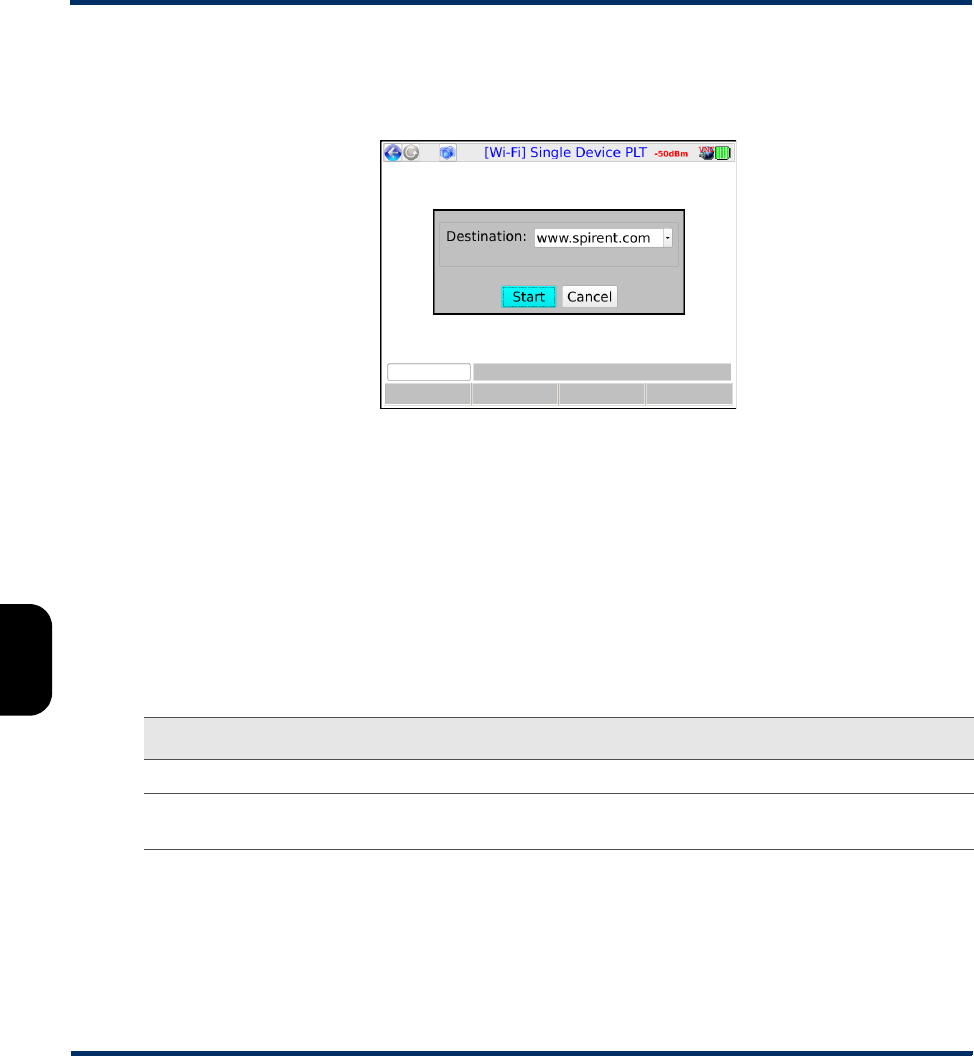
6.7.1 Setup - Single Device PLT
The setup requires only the Destination for the ping tests:
Figure 6-7 Single Device PLT - Setup
CAUTION: You should select the destination for this test carefully. Because it effectively
sends a continuous stream of packets to a single host, it could be construed as
a denial-of-service attack by a third party that does not welcome such traffic.
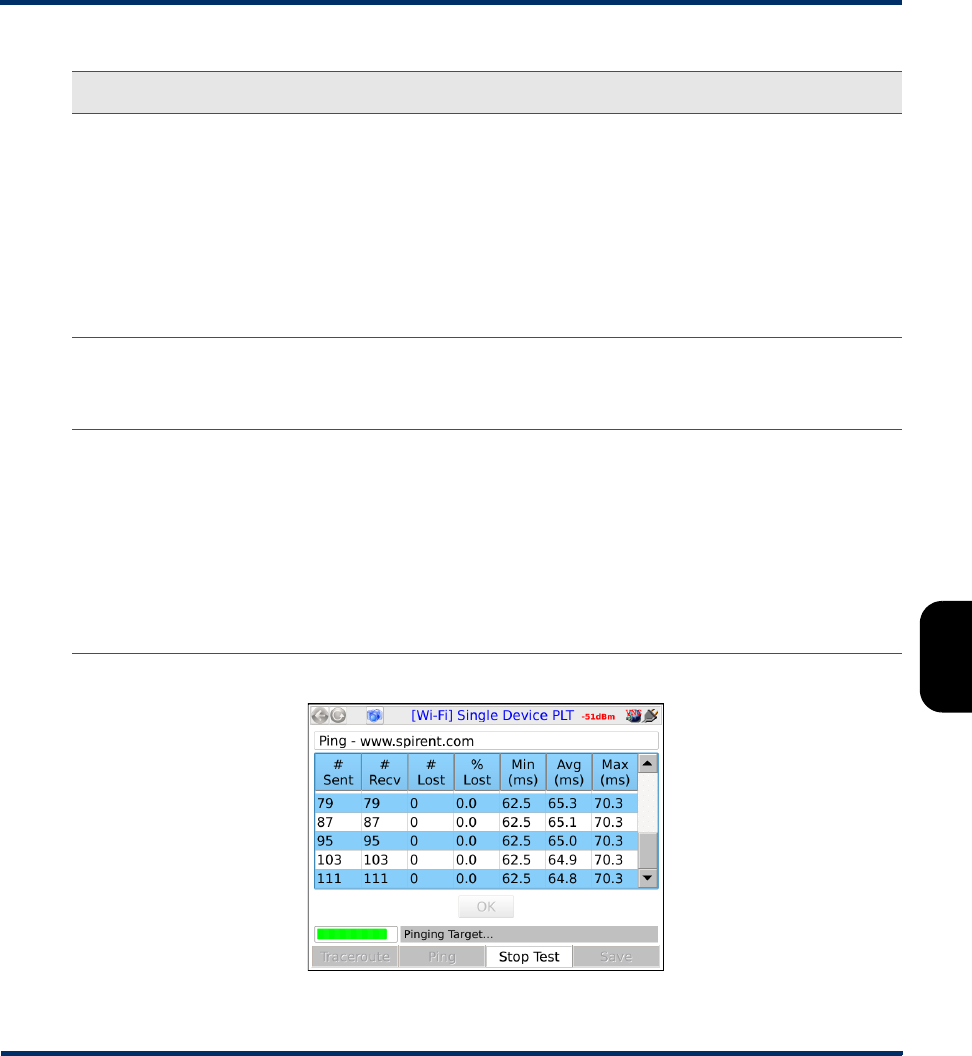
6.7.2 Results - Single Device PLT
The test runs indefinitely until manually stopped. Results are reported at approximately 1-second
intervals and are as follows:
Table 6-9 Single Device PLT results
Measurement Description
# Sent Total number of ping requests sent since the beginning of the test.
# Recv The total number of ping requests that successfully received a reply, as of the end of
the respective reporting interval.
Preliminary issue - Limited distribution only!
Tech-X Flex® (NG2) Tech-X Flex User Guide - Firmware v06.50
6-13
Intro
Overview
Wi-Fi
Ethernet
System
IP/Video
MoCA
RF
Specs
Figure 6-8 Single Device PLT - Results
# Lost The total number of ping requests that have not yet received a reply, calculated as:
# Sent - # Received
Note that this number may fluctuate up and down, as a reply may be received in one
interval for a request sent in a previous interval. Therefore, at any given time during
ongoing testing, this number does not necessary represent a count of positively lost
packets, because some may still be in transit. Once a test is terminated, it will wait a
standard amount of time for any lingering requests to be acknowledged and/or time
out, so the count for the final interval will be an accurate count of loss for the entire
test.
% Lost The percent of packets lost since the beginning of the test, calculated as:
# Lost / # Sent
...using the cumulative counts for the respective interval only.
Min
Avg
Max
The minimum, average, and maximum roundtrip times since the beginning of the
test, not necessarily for the respective interval. Because these counts represent the
entire test, the following notes apply:
•The Min value cannot ever increase from one interval to the next, because new
minimums can only reduce the value.
•The Max value follows a similar logic except that it cannot decrease.
•The Avg value may fluctuate based on changing conditions during the testing
process. The longer the test runs, the more likely this value will stabilize as the
number of data points contributing to the calculations continues to increase.
Measurement Description
Preliminary issue - Limited distribution only!

Tech-X Flex User Guide - Firmware v06.50 Tech-X Flex® (NG2)
6-14
Intro Overview Wi-Fi Ethernet System IP/Video MoCA RF Specs
6.8 Throughput
The Throughput test calculates the maximum data rate to and from a specific endpoint, designed as a
basic upstream/downstream capacity measurement. The target endpoint of the test must be a computer
running a webserver application that is specifically configured for this test. For more information, see
Throughput server setup on page 6-16.
Note the following:
• While running this test, keep in mind that throughput in any direction can never be greater than the
slowest segment in the path. Therefore, for proper interpretation of results, you should have some
awareness of which segment is expected to have the lowest throughput under normal conditions.
• This test is based on a transfer of data over a TCP connection. TCP data rates may vary dynamically
during the course of transmission; therefore, results between different file sizes and different tests
may be inconsistent. In particular:
– Large file sizes may indicate a higher data rate than smaller sizes, because the endpoints will
have more time to optimize the TCP link.
– TCP involves retransmissions of lost data, which can have a varying effect depending on what
stage(s) of the file transfer that the retransmission(s) occur. For example, if loss occurs later in the
transfer when the TCP window size may be allowing larger units of transfer, a retransmission will
be more costly to the overall data rate.
In summary, while this test may be useful for determining a baseline for the user experience, it cannot
provide a precise or consistent data rate measurement at the lower data link layer.
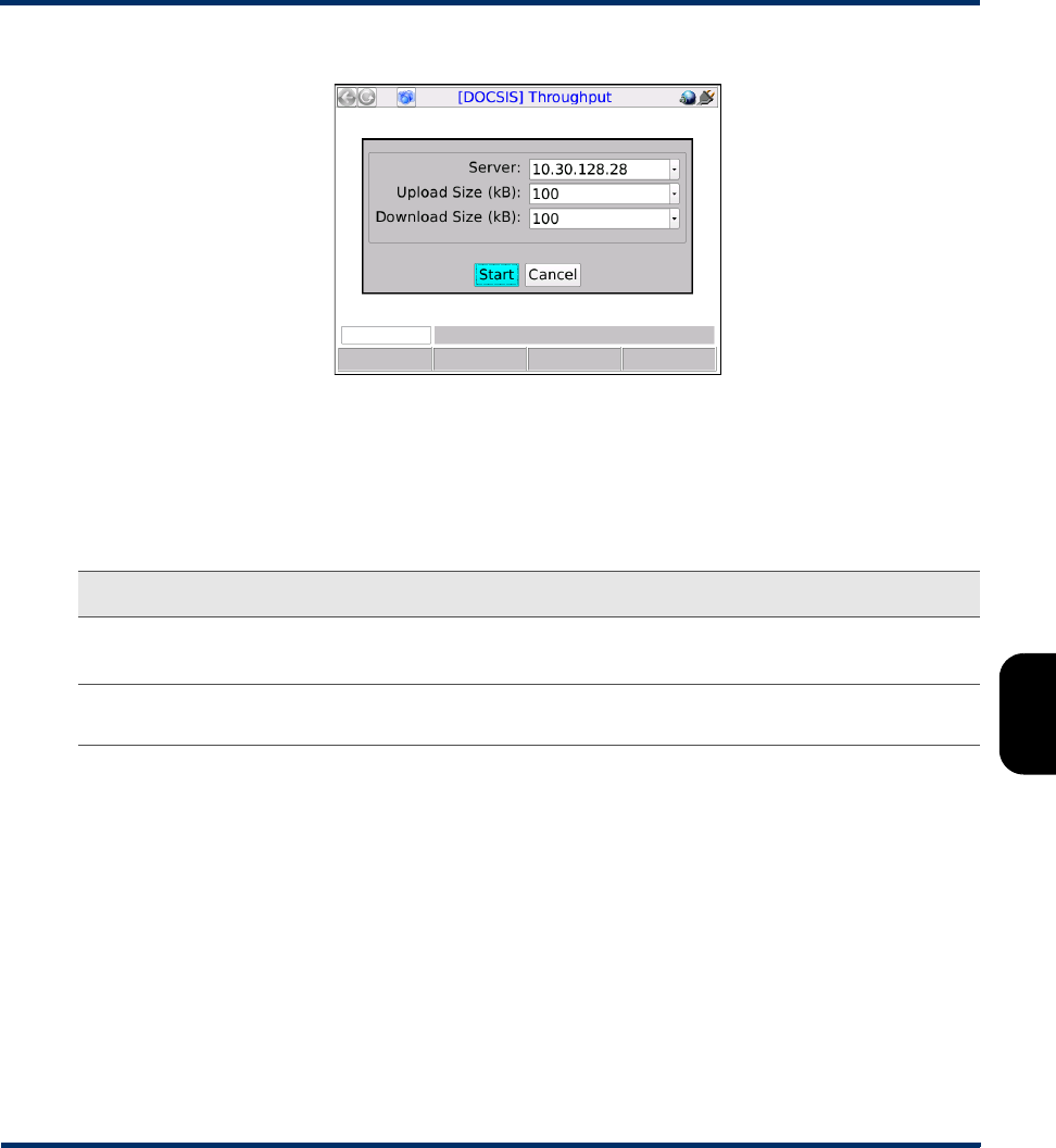
6.8.1 Setup - Throughput
The setup screen requires the following parameters:
Table 6-10 Throughput setup parameters
Measurement Description
Server IP address of a properly-configured throughput server running on port 80 (see
Throughput server setup on page 6-16). A URL is also acceptable if a valid DNS
was assigned during IP Network Setup (see IP Network Setup on page 6-1).
Upload Size (kB)
Download Size (kB)
Total amount of data to send in each direction, up to 100,000 kilobytes each
direction. For each direction, the test measures the amount of time required to
send the respective amount of data and uses that measurement to calculate the
overall data rate. Larger amounts of data facilitate greater accuracy but increase
testing time and bandwidth consumption.
Preliminary issue - Limited distribution only!
Tech-X Flex® (NG2) Tech-X Flex User Guide - Firmware v06.50
6-15
Intro
Overview
Wi-Fi
Ethernet
System
IP/Video
MoCA
RF
Specs
Figure 6-9 Throughput - Setup
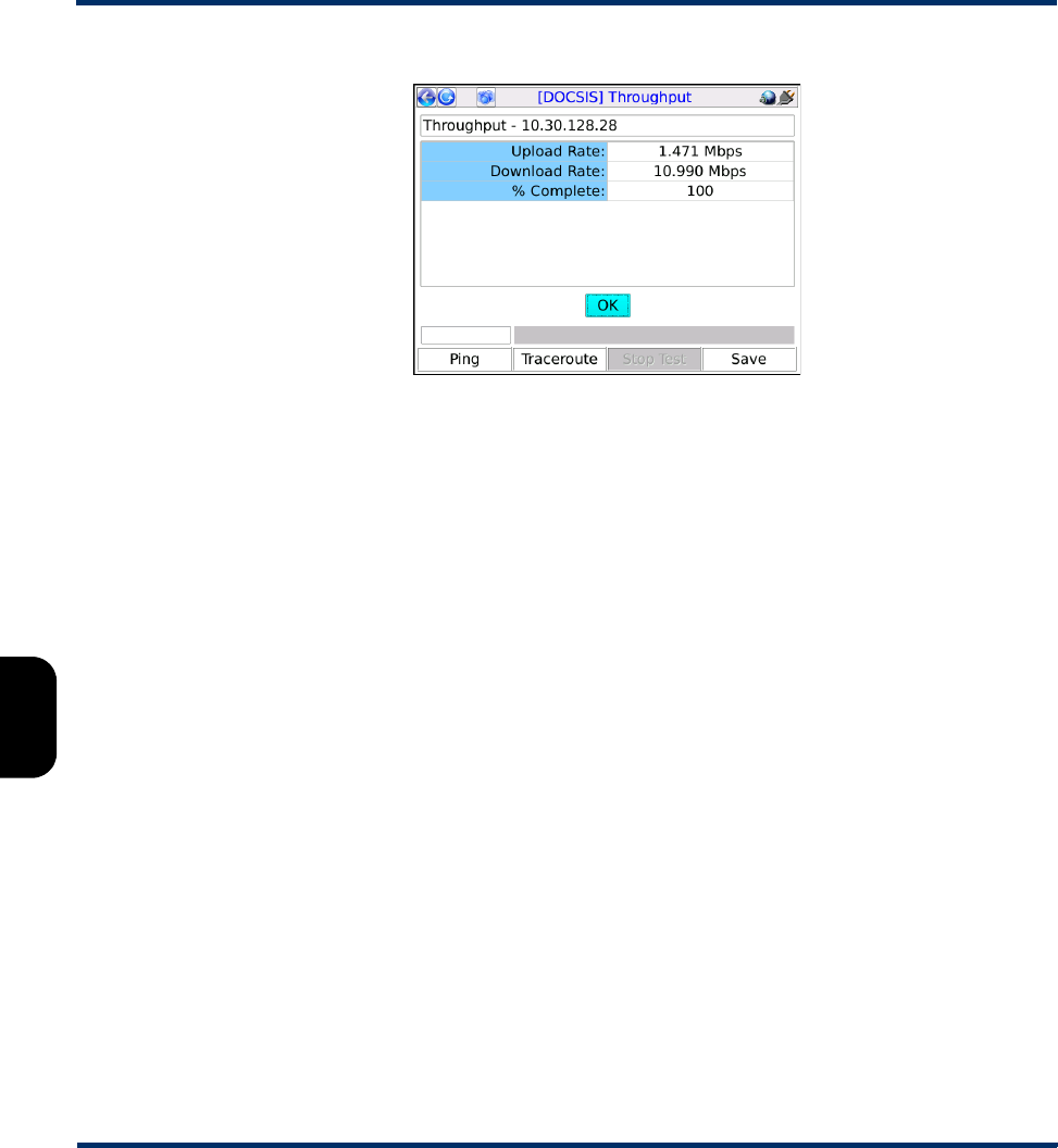
6.8.2 Results - Throughput
The test produces the following results:
Table 6-11 Throughput results
Measurement Description
Upload Rate
Download Rate
Maximum achievable data rates in both directions, averaged across the testing
period.
% Complete A progress counter that increments while the test is running, until it is 100%
complete.
Preliminary issue - Limited distribution only!
Tech-X Flex User Guide - Firmware v06.50 Tech-X Flex® (NG2)
6-16
Intro Overview Wi-Fi Ethernet System IP/Video MoCA RF Specs
Figure 6-10 Throughput - Results
6.8.3 Throughput server setup
The Throughput test requires a testing destination that is specifically designed to recognize and process
throughput exchanges with the unit. This destination must be an HTTP (web) server running on a
networked computer and installed with Spirent-specific components. The following procedure is a broad
overview of server installation and setup.
NOTE: To accomplish this task successfully, a basic knowledge of web server administration and
python scripting is recommended. For assistance with setup and troubleshooting, please
contact Spirent.
1. Download and install the web server - The supported web server is the Apache HTTP Server,
available at the time of this writing at:
http://httpd.apache.org/download.cgi
You should select the most recent stable (alpha) release for your platform (Windows, etc.). Install it
using default parameters except for the requested web administrator email address, which you may
want to change to the real address of an administrator (perhaps yourself). Note the following:
• The server must be set to listen on port 80 for HTTP requests.
• Depending on the platform and installation type, you may need to manually start the server
following installation. See the Apache documentation for more information.
2. Download and install an ActiveState python package - At the time of this writing, the latest stable
python packages are available at:
http://www.activestate.com/activepython/downloads/
Preliminary issue - Limited distribution only!

Tech-X Flex® (NG2) Tech-X Flex User Guide - Firmware v06.50
6-17
Intro
Overview
Wi-Fi
Ethernet
System
IP/Video
MoCA
RF
Specs
Default installation settings are recommended.
3. Retrieve and install the Spirent python scripts - You must place two python scripts (*.py) files in
the cgi-bin directory in the Apache installation area. These files are available from Spirent,
normally from the corporate/customer FTP site at the following address:
ftp.sab.spirentcom.com
For login credentials, please contact your account manager.
6.9 Speedtest
The Speedtest provides a standard internet-based maximum throughput test. By exchanging data with
an internet endpoint, it attempts to determine the maximum data rate supported in both the uplink and
downlink directions. Note that this test may put a temporary strain on the local network, as it is attempting
to exchange the maximum amount of data possible.
This test is a purchasable option. Please contact Spirent for more information.
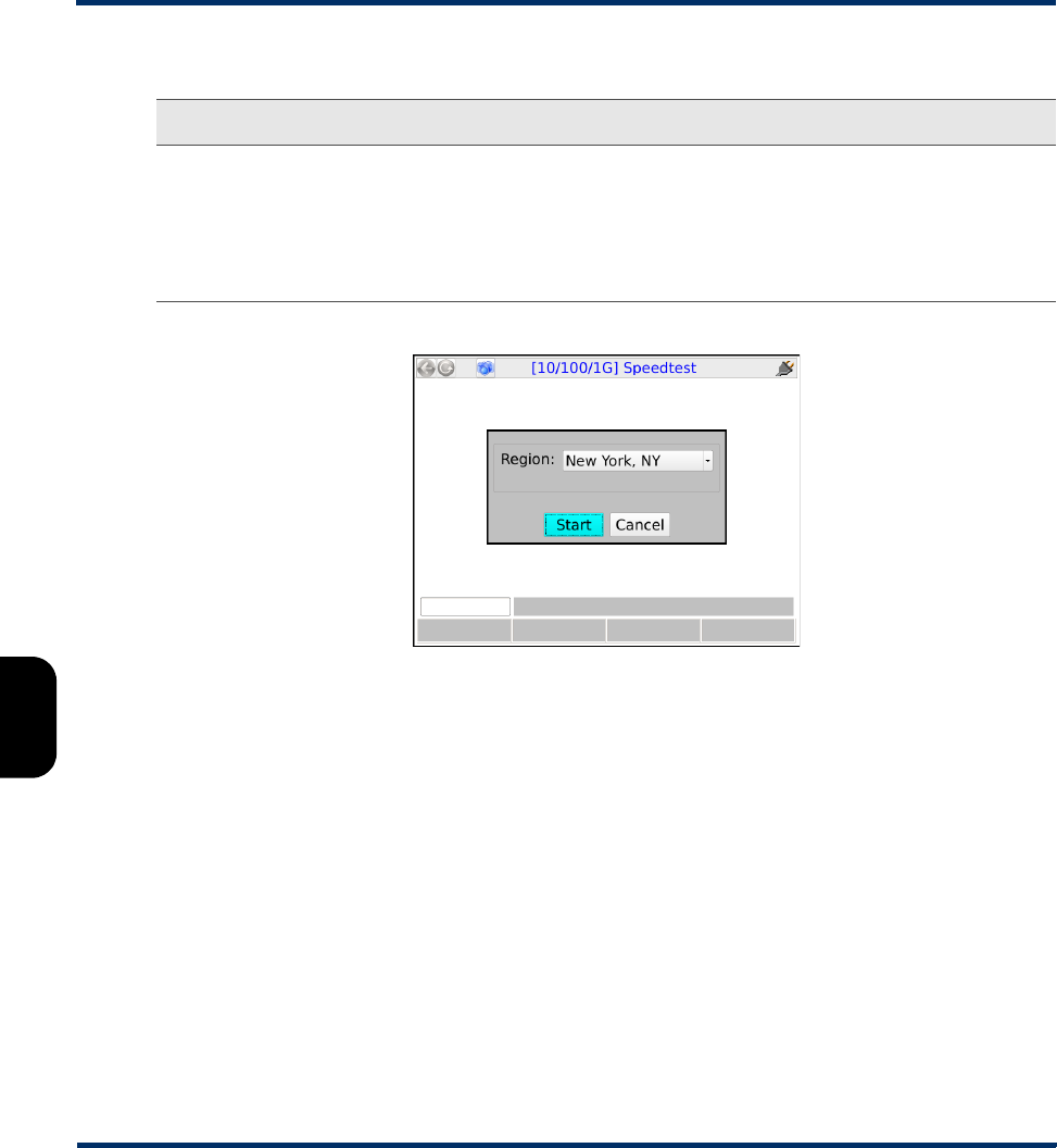
6.9.1 Setup - Speedtest
The setup screen requires the following parameters:
Important note: The python scripts are currently configured for Windows usage only and require
that the system path environment variable contains the path to the python executable. If you are
using Windows, you should ensure that this variable is set correctly.
If you are using Linux or Unix instead, you must adjust the first line of each script to point to the
location of the python interpreter, for example:
#!/usr/bin/python
If the system is unable to locate the python interpreter based on this line, throughput testing will
fail. For more information, see the operating system documentation, python documentation,
and/or contact Spirent.
Preliminary issue - Limited distribution only!
Tech-X Flex User Guide - Firmware v06.50 Tech-X Flex® (NG2)
6-18
Intro Overview Wi-Fi Ethernet System IP/Video MoCA RF Specs
Table 6-12 Speedtest setup parameters
Figure 6-11 Speedtest - Setup
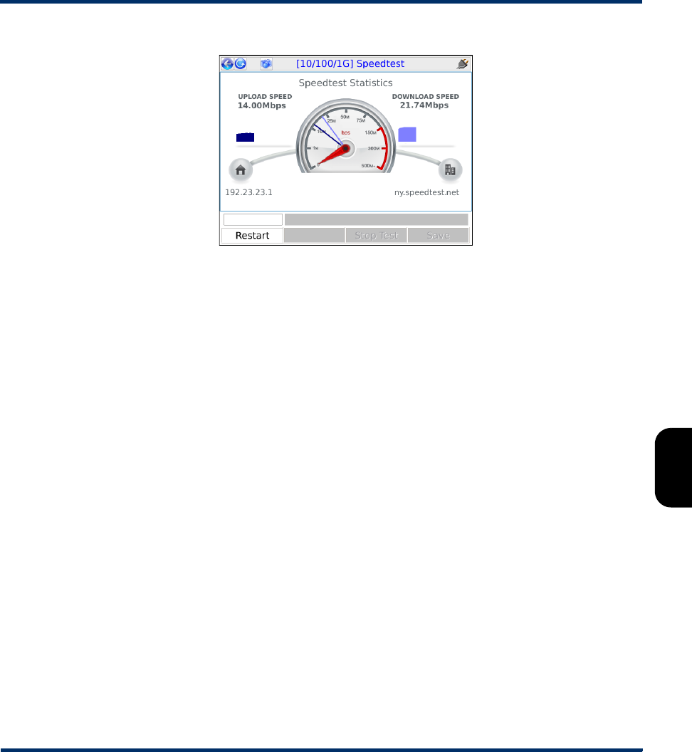
6.9.2 Results - Speedtest
NOTE: While the test is actively sending traffic, the screen presents a “collecting data” message and
does not update further until the traffic exchange is complete. It may take up to a minute to
complete this exchange, after which the final results are presented graphically.
The test produces a simple graphical display of the maximum speeds achieved for upload and download.
Measurement Description
Region General location of the target endpoint. The options in the list represent
designated endpoints that are specifically provided for this test. These locations,
along with the underlying IP addresses, are hardcoded with the unit firmware.
Normally, you should select the geographically closest location. For more
information on these locations, contact a local administrator. For more
information on augmenting this list, please contact Spirent.
Preliminary issue - Limited distribution only!
Tech-X Flex® (NG2) Tech-X Flex User Guide - Firmware v06.50
6-19
Intro
Overview
Wi-Fi
Ethernet
System
IP/Video
MoCA
RF
Specs
Figure 6-12 Speedtest - Results
6.10 All Devices Packet Loss (Device Discovery)
The All Devices Packet Loss test runs a series of ping tests to one or more IP hosts on the LAN,
maintaining and presenting a set of cumulative results as testing progresses. Results are focused on the
number of packets that are lost; that is, for which the unit never receives a reply. Note that:
• Initially, the test automatically detects all IP hosts on the LAN and presents a list of addresses, from
which you can select the specific hosts you want to target with the ping testing stage. Testing to all
selected hosts occurs simultaneously.
• This test is effectively the same as Device Discovery, which appears in some menus instead of All
Devices Packet Loss. The naming difference is due to the likely intended purpose; that is, whether
the test will be used to discover devices only or to continue with packet loss testing. Regardless of
the source menu or test name, you can choose whether or not to continue with packet loss testing.
• For any given host, the ping testing stage is similar to the single-target Packet Loss Test (see Single
Device PLT on page 6-11).
6.10.1 Setup - All Devices Packet Loss
When initiated, the test behaves differently according to the active interface:
•Wi-Fi or 10/100 - The host detection stage starts immediately.
•MoCA - The unit prompts you to select MOCA-specific options related to the BHR. For more
information, see Special MoCA BHR considerations - All Devices Packet Loss on page 6-21.
Preliminary issue - Limited distribution only!
Tech-X Flex User Guide - Firmware v06.50 Tech-X Flex® (NG2)
6-20
Intro Overview Wi-Fi Ethernet System IP/Video MoCA RF Specs
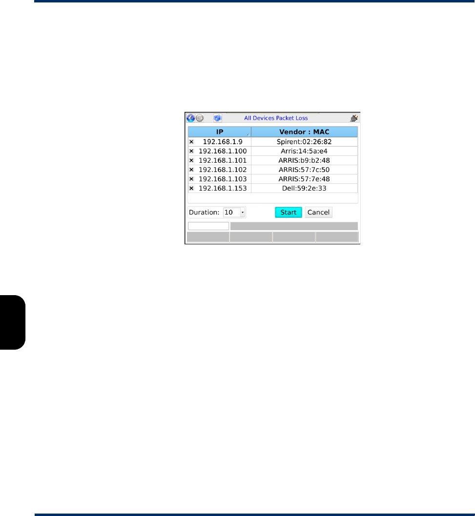
Following host detection, some addresses may be automatically selected and some may not. You should
ensure that the selection(s) are correct for the test, as well as select the testing Duration that applies to
all target hosts.
NOTE: At this point, if device detection was the only original purpose, you can review the results and
safely cancel the packet loss portion of the test.
Figure 6-13 All Devices Packet Loss - Setup following the host detection phase
The duration may be selected from the list or entered manually, up to 60 seconds. Alternatively, you can
select Continuous for a test that runs until manually stopped.
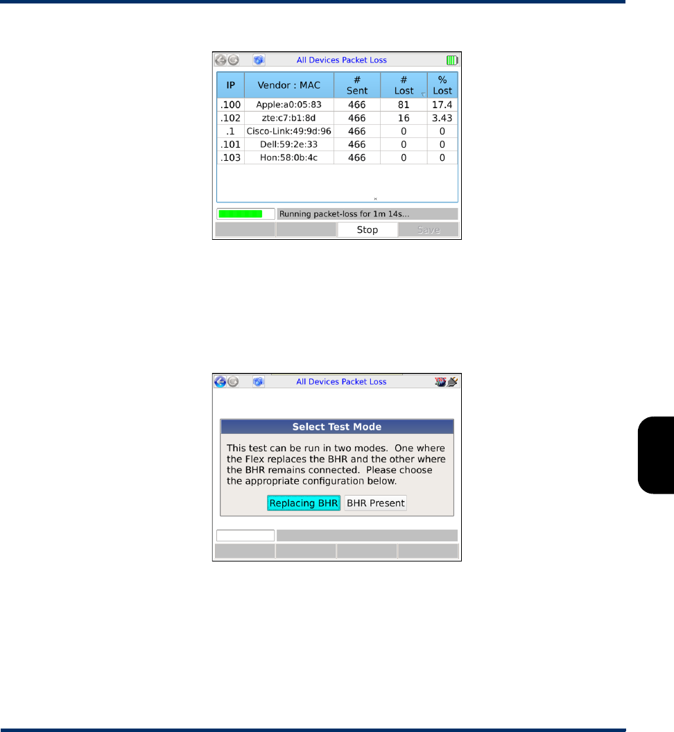
6.10.2 Results - All Devices Packet Loss
The test sends ping packets to all hosts simultaneously and reports a running total of packets sent and
lost:
Preliminary issue - Limited distribution only!
Tech-X Flex® (NG2) Tech-X Flex User Guide - Firmware v06.50
6-21
Intro
Overview
Wi-Fi
Ethernet
System
IP/Video
MoCA
RF
Specs
Figure 6-14 All Devices Packet Loss - Results (Continuous test)
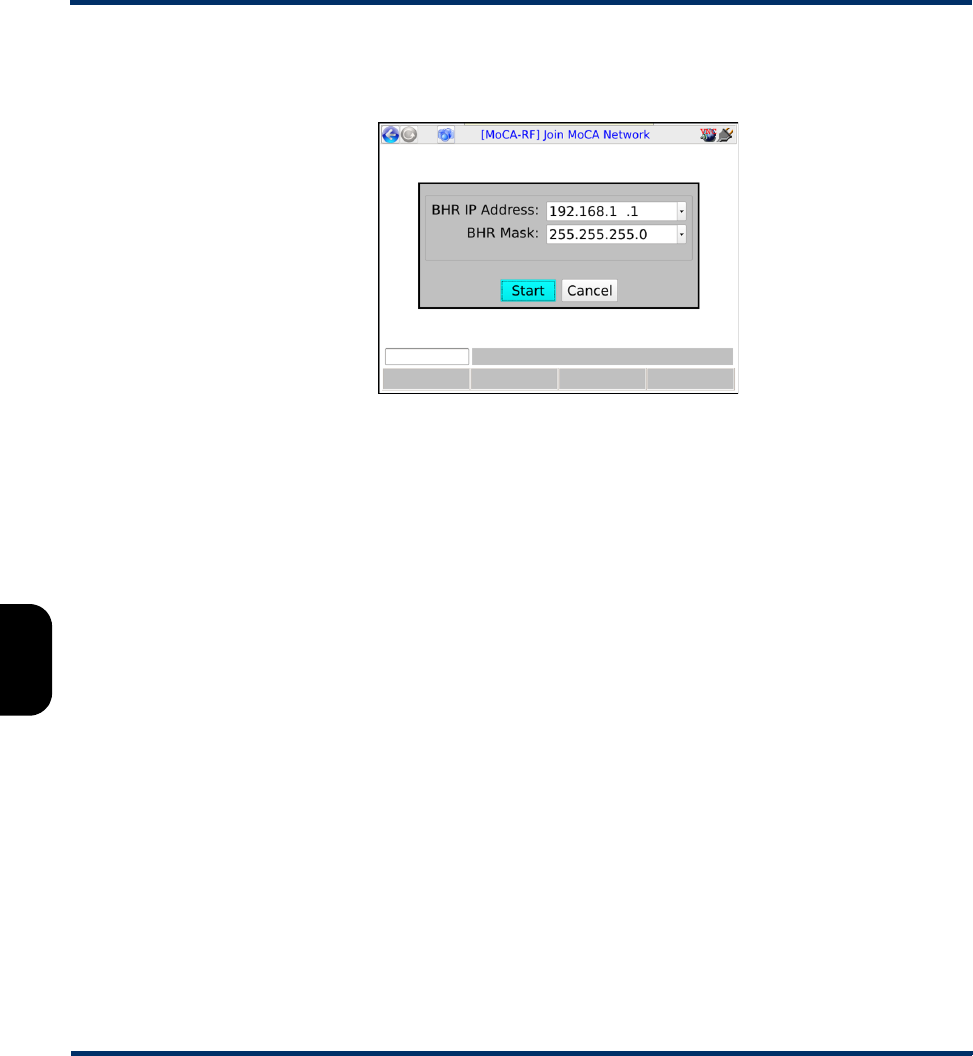
6.10.3 Special MoCA BHR considerations - All Devices Packet Loss
On a MoCA network, the test can run on a LAN with or without an active router (BHR). To support both
scenarios, you must first select one of the following options when the test is launched with the MoCA
interface active:
Figure 6-15 All Devices Packet Loss - MoCA test mode prompt
•Replacing BHR - With this mode, the unit assumes that no router is present and serves as a basic
DHCP server. During the host detection stage, any active devices should receive a short-lease IP
address, suitable for completing the remainder of testing.
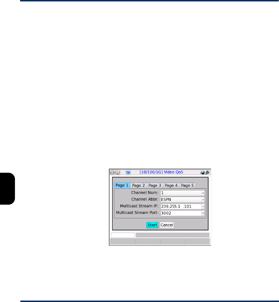
If this option is chosen, the unit produces a subsequent prompt for the BHR IP Address and the BHR
Mask. These settings allow the unit to simulate the router and distribute IP addresses that will be
routable on the normal BHR-hosted LAN. If you specify values that do not represent the normal LAN,
Preliminary issue - Limited distribution only!
Tech-X Flex User Guide - Firmware v06.50 Tech-X Flex® (NG2)
6-22
Intro Overview Wi-Fi Ethernet System IP/Video MoCA RF Specs
a LAN host may receive an address that is not routable once a router is connected; however, testing
may still succeed.
Figure 6-16 All Devices Packet Loss - BHR IP parameters
•BHR Present - This mode assumes that a router is functioning normally on the LAN and no DHCP
server on the unit is required.
After these options are resolved, the remainder of testing follows the normal host detection and ping
testing stages. Note the following:
• When the Replacing BHR option is selected, the unit assumes that the IP information provided will
be used to configure the MoCA IP interface. For this reason, the IP Network Setup function is not a
prerequisite to launch the All Devices Packet Loss test, unlike most other IP-related tests. If it has
already been run, the unit will prompt you to drop the current IP configuration before proceeding with
the All Devices Packet Loss test.
•If the BHR Present option is chosen but IP Network Setup has not been run yet, a DHCP-based
address assignment will occur automatically.
• The concept of replacing the router only applies to the MoCA interface because the unit can connect
to all LAN devices via a single coax, by nature of the MoCA environment. For a 10/100/1G network,
the unit would require a separate port for each device.
6.11 IP Video testing
IP video testing support includes:
Preliminary issue - Limited distribution only!

Tech-X Flex® (NG2) Tech-X Flex User Guide - Firmware v06.50
6-23
Intro
Overview
Wi-Fi
Ethernet
System
IP/Video
MoCA
RF
Specs
• Subjective quality assessment of viewer experience
• Comprehensive statistics on multimedia transport streams
• Video channel change times
Video testing support includes:
• “Active” testing, where the test set emulates a multicast endpoint and performs all actions necessary
to start and/or join the stream. Depending on the location of the test set, this type of testing can
provide the most comprehensive view of the actual subscriber experience.
• “Passive” testing, where the test set is connected between two existing endpoints and passively
monitors the video traffic between them. Passive testing is supported for multicast and unicast
streams.
Briefly, unicast vs. multicast is defined as:
•Unicast - A single stream between two specific endpoints. Unicast video is similar to any
conversation between distinct IP hosts, which in this case normally represent a video server and a
subscriber device such as an STB.
•Multicast - A system designed to transport a single video stream to multiple endpoints, reducing the
demands on network bandwidth due to redundant data. For more information, see About IP multicast
on page 6-43.
For any given interface, note that testing support may vary according to limitations specific to that
interface. Where appropriate, this documentation notes those variations.
Specific video functions include:
•Video QoS (Quality of Service) on page 6-23
•Change Channel on page 6-51
•Channel Guide Settings on page 6-53
6.11.1 Video QoS (Quality of Service)
NOTE: Video testing is a purchasable option. Please contact Spirent for more information.
This test provides subjective no-reference quality scores and MDI calculations on a specific IPTV
channel stream, along with a set of network parameters, picture frame statistics, and other transport
stream information.
For a single-ended, active test, the unit must emulate a video endpoint and initiate/join the stream, after
which it performs the quality assessment on the traffic sent directly to it. Some interfaces, such as the
10/100/1G interface, provide a bridging/mirroring mechanism where the unit can be placed between two
Preliminary issue - Limited distribution only!
Tech-X Flex User Guide - Firmware v06.50 Tech-X Flex® (NG2)
6-24
Intro Overview Wi-Fi Ethernet System IP/Video MoCA RF Specs
devices and passively monitor an existing stream. For more information on how the passive bridging
process works with the Ethernet interface, see Unit setup for passive testing on page 4-4.
For more details on how the quality assessment works, see How the analysis works - An overview on
page 6-45.
NOTE: The analysis focuses primarily on the data captured from the MPEG transport stream. For more
information about MPEG transport, see the information under Digital video concepts overview
on page 6-39, including About MPEG transport on page 6-41.
Setup - Video QoS
Note the following:
• For multicast testing, if the unit has an active channel guide, the display will first present a channel
selection screen when the test setup is initiated. After channel selection, the normal setup screen will
appear, with the certain parameters prepopulated, such as the IP address and port. The use of a
channel guide, if available, is generally recommended. For more information, see Channel Guide
Settings on page 6-53.
• When you run a test, the input parameters are stored as defaults for the next test and persist between
reboots. The defaults are stored separately for each interface that supports Video QoS testing. For
example, the settings used for testing from the 10/100/1G interface would be stored separately from
those used for the modular MoCA interface.
Figure 6-17 Multicast Video QoS Setup - Page 1 (with a channel guide)
Preliminary issue - Limited distribution only!

Tech-X Flex® (NG2) Tech-X Flex User Guide - Firmware v06.50
6-25
Intro
Overview
Wi-Fi
Ethernet
System
IP/Video
MoCA
RF
Specs
Table 6-13 Video QoS test - Setup parameters
Parameter Description
Channel Num
Channel Abbr
For multicast video only, if a channel guide was used, the channel number and
abbreviation that was selected in the previous screen. If no channel guide is
active, these fields do not appear. For more information on channel guides, see
About channel guides on page 6-53.
Multicast Stream IP
-or-
Destination IP Addr
IP address of the video stream. For multicast video, if you selected a channel
from the channel guide, this field is automatically populated.
The IP address specified must reflect the destination IP address for video stream
packets; that is, the first address contained in the IP packet headers. For a
multicast stream, this will be a multicast IP address, not an IP address of a host
on the network under test. For a unicast stream, this must be the IP address of
the destination device on the network, such as an STB. For a discussion on
multicast packet addressing and transport versus unicast, see About IP multicast
on page 6-43.
Multicast Stream
Port
-or-
Destination IP Port
The destination UDP port associated with packets that contain the stream under
test. The unit determines which packets should be included in the audio/video
quality measurement based on the destination IP address and destination UDP
port pair. For multicast video, if you selected a channel from the channel guide,
this field is automatically populated.
As an option, you can select All Ports Open from the drop-down list which
indicates to ignore the port and use the IP address exclusively for identifying
video stream packets. In the case of unicast streams where packets are
addressed to a network device such as an STB, it can be difficult to determine
the UDP port(s) in use. Therefore, this option allows traffic analysis based on IP
address alone. While the STB may be receiving some data that is not part of the
video stream, it is likely that most traffic will be video data that qualifies for
analysis.
NOTE: For the most accurate results with the All Ports Open option, run
the test once to discover the precise port number, then restart the test
using that specific port.
In summary:
• This field indicates the logical port that the unit will monitor for video traffic, for
the specified IP address.
•The All Ports Open option is only applicable to measuring unicast streams
(for example, video-on-demand) using passive mode. The option allows the
unit to determine the destination UDP port of the packets containing the
stream under test dynamically.
Preliminary issue - Limited distribution only!

Tech-X Flex User Guide - Firmware v06.50 Tech-X Flex® (NG2)
6-26
Intro Overview Wi-Fi Ethernet System IP/Video MoCA RF Specs
Duration Duration of the test in seconds, or Continuous to run the test until manually
stopped.
Interval Interval at which to report a full set of current measurement results, applicable to
continuous tests only.
Encapsulation
Method
Encapsulation type of the stream(s) under test.
•RTP
•UDP
Measurement
Method
Measurement method to use, which determines the type of data returned by the
test. For more information, see About MOS and R-factor calculations on
page 6-46 and MDI measurement overview on page 6-48.
•VQM - See Video quality measurement (VQM) overview and additional results
descriptions on page 6-45.
•MDI - See MDI measurement overview on page 6-48.
Note that this selection fundamentally changes the nature of the analysis and the
results that are returned. For the results from a VQM test, see Results - Video
QoS (VQM test) on page 6-31. For the results from an MDI test, see Results -
Video QoS (MDI test) on page 6-30.
IGMP Version Version of IGMP to use for multicast join/leave requests. This must reflect an
IGMP type in use on the network where the request is made.
Options include:
•IGMPV1 - IGMP version 1
•IGMPV2 - IGMP version 2
•IGMPV3 - IGMP version 3
Codec Video codec used for the stream under test.
•MPEG2
•MPEG4
•H264
Parameter Description
Preliminary issue - Limited distribution only!

Tech-X Flex® (NG2) Tech-X Flex User Guide - Firmware v06.50
6-27
Intro
Overview
Wi-Fi
Ethernet
System
IP/Video
MoCA
RF
Specs
Jitter Mode Type of jitter buffer emulation used.
Options include:
•FIXED - The jitter buffer uses a constant fixed delay. The jitter buffer is
bounded by a nominal and maximum delay, where the nominal delay dictates
the actual delay and the maximum delay dictates the maximum number of
packets that can be stored in the jitter buffer.
•ADAPTIVE - The jitter buffer is bounded by a minimum, nominal and
maximum delay, where the minimum delay dictates the minimal accepted jitter
buffer delay, nominal delay dictates the starting delay and the maximum delay
dictates the maximum delay of the jitter buffer. The maximum number of
packets that can be stored in the jitter buffer is a set fraction of the maximum
delay.
GOP Type Video coder group of pictures (GOP) structure, representing the frame sequence
in use on the stream with respect to I, P, and B frames. This value is used only as
a default if the actual frame types and GOP structure cannot be dynamically
detected from the stream.
Options include:
•A - I-frames only, for example:
III…I
•B - One I-frame followed by P-frames, for example:
IPPP...PIPPP...
•C - One I-frame followed by P- and B-frames with two B-frames between each
pair of anchor frames, for example:
IBBPBBP...BBIBBP...
•D - All P-frames, for example:
PPPP...P
•E - One I-frame followed by P- and B-frames with one B-frame between each
pair of anchor pictures, for example:
IBPBP...BIBP...
For more information about MPEG pictures, see About IP multicast on
page 6-43.
Parameter Description
Preliminary issue - Limited distribution only!

Tech-X Flex User Guide - Firmware v06.50 Tech-X Flex® (NG2)
6-28
Intro Overview Wi-Fi Ethernet System IP/Video MoCA RF Specs
GOP Length Number of frames in a group of pictures (GOP) on the stream, related to the
GOP type. This is essentially the I-frame update interval; that is, the number of
frames from one I-frame to the next. This value is used only as a default if the
actual frame types and GOP structure cannot be dynamically detected from the
stream.
Range:
1 - 100
Loss Sensitivity This defines how much the quality assessment should be sensitive towards
packet loss and discards. A higher value indicates the video stream is more
sensitive to packet loss/discard. When set higher, the calculation model will
respond more rapidly to packet loss on the network under test, and packet loss
will have a greater impact on the calculated score. If set lower, the results will be
less affected by packet loss. This setting makes the analysis tunable for different
varieties of encoders and various network environment conditions.
Concealment Level This parameter defines the effectiveness of the packet loss concealment
algorithm use by the encoder. A higher value indicates a better PLC algorithm.
This setting helps compensate for reduced packet loss due to regeneration by
technologies such as forward error correction (FEC). In other words, it affects
how sensitive the quality assessment is to packet loss, with some similarity to the
loss sensitivity setting. A higher setting indicates that overall packet loss will
affect the quality score less. A setting of zero or none indicates no concealment,
meaning that packet loss will have the most impact to video quality, with respect
to this parameter's influence.
Valid values are:
0 to 50
Complexity This parameter defines the video content coding factor. A higher value indicates
the video stream can be encoded using a lower bit rate to achieve a given
quality.
Valid values are:
-50 to 50
Original Quality Original picture quality. This value represents the subjective quality of the video
before encoding, which is the theoretical maximum that the quality ever could be
after encoding, transport, and decoding.
Valid values are:
256 - 1280, proportional to the 1.0 to 5.0 MOS range, scaled by a factor of 256.
For example, a value of 1242 is equivalent to a MOS of 4.85.
Parameter Description
Preliminary issue - Limited distribution only!

Tech-X Flex® (NG2) Tech-X Flex User Guide - Firmware v06.50
6-29
Intro
Overview
Wi-Fi
Ethernet
System
IP/Video
MoCA
RF
Specs
Coder Class Video coder class, which describes the ability of the stream to tolerate packet
loss with respect to perceived quality. The coder class is determined by two
contributing factors:
• Codec - Some codecs, particularly older codecs, are very sensitive to packet
loss and degrade very quickly with small amounts of loss.
• Error correction and concealment - A number of loss mitigation techniques
may be employed to conceal packet loss, typically involving coordination
between the video server and client where checksum and other validation
methods allow missing data to be supplemented.
The specified value determines how heavily the analysis weights the effects of
packet loss. For example, if you specify an operation at high rates of loss, any
detected loss will have less of an effect on final quality scores. This is normally a
static setting on any given network that does not change between tests.
Valid values are:
•A - Stream can operate over networks with up to 20% packet loss
•B - Operation with up to 10% loss
•C - Operation with up to 5% loss
•D - Operation with up to 0.5% loss
International Code Country/continent code, used to adjust quality scores based on cultural
differences in different global regions. For example, subjective human testing
using the same video stream have indicated that MOS scores in Japan are
typically lower than those found in Europe and North America. It should be noted
that this setting is purely subjective based on existing statistical data and cannot
be assured to accurately represent any particular individual.
Valid values are:
•NA - North America
•SA - South America
•EU - Europe
•AF - Africa
•AS - Asia
•JP - Japan
•AUS - Australia
Parameter Description
Preliminary issue - Limited distribution only!
Tech-X Flex User Guide - Firmware v06.50 Tech-X Flex® (NG2)
6-30
Intro Overview Wi-Fi Ethernet System IP/Video MoCA RF Specs
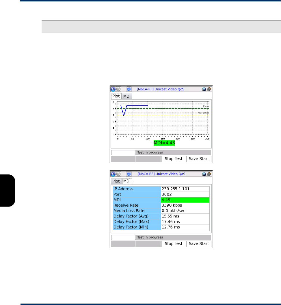
Results - Video QoS (MDI test)
Figure 6-18 Video QoS results - MDI test
Nominal Rate Payload media rate (audio and video) in kbps, used in calculating the MDI delay
factor.
Valid values are:
0 - 20000, where 0 indicates auto-detection of rate.
Parameter Description
Preliminary issue - Limited distribution only!

Tech-X Flex® (NG2) Tech-X Flex User Guide - Firmware v06.50
6-31
Intro
Overview
Wi-Fi
Ethernet
System
IP/Video
MoCA
RF
Specs
Results - Video QoS (VQM test)
Test results are presented in three different screens, each of which has two different pages. Use the
appropriate function key to switch between screens. Note the following:
• All quantitative measurements apply to the reporting period only. No measurements are cumulative.
• Unless indicated otherwise, any reference to “packets” means MPEG packets, not IP packets.
Result Description
IP Address
Port
IP address and port of the media stream, specified at test launch.
Receive Rate Speed of frames received, in kbits/sec. For VQM testing, this is the receive rate
of the video or audio stream, as applicable. For MDI testing, this is the receive
rate of the PCR stream.
MDI
Media Loss Rate
Delay Factor (Avg)
Delay Factor (Max)
Delay Factor (Min)
See MDI measurement overview on page 6-48.
NOTE: The MDI result is colored green or red according to the fixed
pass/fail thresholds shown in the Plot tab.
Preliminary issue - Limited distribution only!
Tech-X Flex User Guide - Firmware v06.50 Tech-X Flex® (NG2)
6-32
Intro Overview Wi-Fi Ethernet System IP/Video MoCA RF Specs
Table 6-14 Video QoS results - Summary results, Plot tab
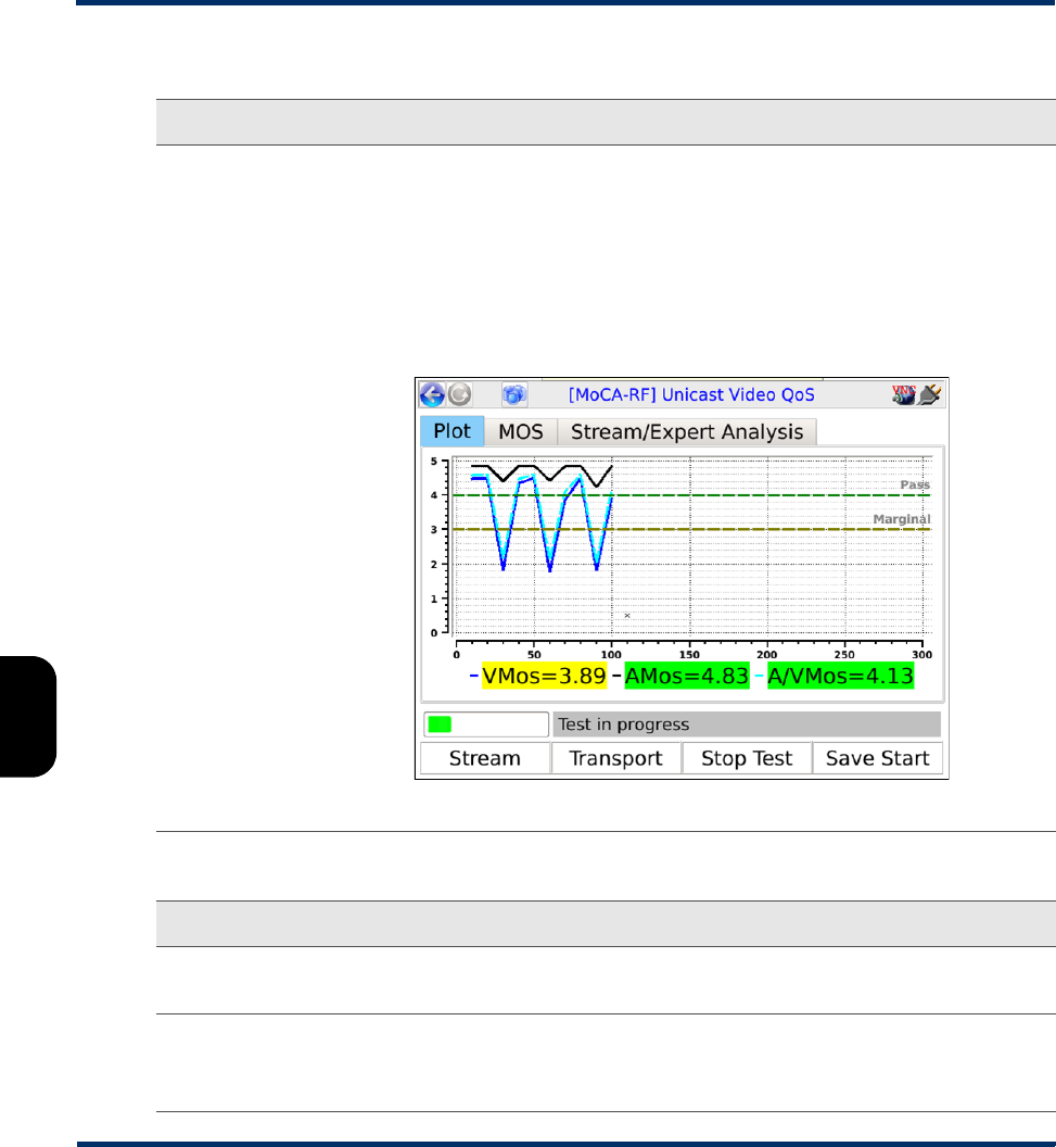
Table 6-15 Video QoS - Summary results, MOS tab
Result Description
MOS graph Displays graph of calculated VMos, AMos, and A/VMos, which updates regularly for
continuous tests. The graph assumes a fixed score of 4.0 as passing and 3.0 as
marginal with coloring as follows:
•Green - Passing (above 4.0)
•Yellow - Marginal (between 3.0 and 4.0)
•Red - Failing (below 3.0)
The standards for any given architecture may differ. For more information on MOS
scoring, see About MOS and R-factor calculations on page 6-46.
Figure 6-19 VQM MOS graph
Result Description
IP Address
Port
IP address and port of the media stream, specified at test launch.
V MOS
A MOS
A/V MOS
See About MOS and R-factor calculations on page 6-46.
NOTE: Results are colored green or red according to the fixed pass/fail
thresholds shown in the Plot tab.
Preliminary issue - Limited distribution only!

Tech-X Flex® (NG2) Tech-X Flex User Guide - Firmware v06.50
6-33
Intro
Overview
Wi-Fi
Ethernet
System
IP/Video
MoCA
RF
Specs
Table 6-16 Video QoS- Summary results, Stream/Expert Analysis tab
Table 6-17 Video QoS - Stream results, Stream Metrics tab
Result Description
Codec Type Stream type, as defined in ITU Spec ISO/IEC 13818-1.
For valid values, see Table 6-24, Other recognized transport streams/PID types on
page 6-38.
Image Size Horizontal resolution, indicating the left-right size of the image, in pixels.
-and-
Vertical resolution, indicating the top-bottom size of the image, in pixels.
Image Type Type of the image.
Valid values are:
•SDTV
•HDTV
Degradation
from Loss
Percentage of the overall quality degradation that can be attributed to network packet
loss.
Degradation
from Jitter
Percentage of the overall quality degradation that can be attributed to jitter buffer
discards.
Degradation
from Codec
Type
Percentage of the overall quality degradation that can be attributed to video
encoder/decoder selection.
Degradation
from Delay
Percentage of the overall quality degradation that can be attributed to delay.
Result Description
Frames Total number of frames received, by type.
Lost Total number of packets lost containing data for the respective frame type; for
example, the total number of packets lost containing I-frame data. These results
are packet counts, not frame counts.
NOTE: If packets for one frame type show an inordinate amount of loss
compared to others, there may be a problem with network congestion
and/or configuration. For example, some NEs may be configured to
discard video B-frame data during periods of heavy congestion.
Preliminary issue - Limited distribution only!

Tech-X Flex User Guide - Firmware v06.50 Tech-X Flex® (NG2)
6-34
Intro Overview Wi-Fi Ethernet System IP/Video MoCA RF Specs
Table 6-18 Video QoS - Stream results, Stream Description tab
Discards Total number of packets discarded by the jitter buffer emulator containing data for
the respective frame type; for example, the total number of packets discarded
containing I-frame data. These results are packet counts, not frame counts.
Impairments Total number of frames errored, by type. A frame is considered errored if a single
packet containing data for it is lost or discarded.
FEC Effect Calculated effectiveness of forward error correction (FEC) if it were applied to the
stream. This value represents the potential effectiveness of applied FEC, not the
effectiveness of previously-applied FEC.
Opt FEC Blk Size Number of packets in an FEC block which is used when calculating the FEC
effectiveness.
Opt FEC Crct Pkts Number of correctable packets in an FEC block which is used when calculating
the FEC effectiveness.
Peak/Mean Rcv
Rate
Ratio of peak packet receive rate to the mean receive rate.
Result Description
GOP Type GOP structure type of the stream. If the structure was detected by the analysis,
this value represents the detected structure. Otherwise, it represents the default
specified at test launch.
For details on possible values, see Setup - Video QoS on page 6-24.
GOP Length GOP length on the stream; that is, the total number pictures in a single GOP. If
the structure was detected by the analysis, this value represents the detected
structure. Otherwise, it represents the default specified at test launch.
Receive Rate Speed of frames received, in kbits/sec. For VQM testing, this is the receive rate
of the video or audio stream, as applicable. For MDI testing, this is the receive
rate of the PCR stream.
Peak Rcv Rate Peak speed of frames received, in kbits/sec. For VQM testing, this is the peak
receive rate of the video stream. For MDI testing, this is the peak receive rate of
the PCR stream.
Result Description
Preliminary issue - Limited distribution only!

Tech-X Flex® (NG2) Tech-X Flex User Guide - Firmware v06.50
6-35
Intro
Overview
Wi-Fi
Ethernet
System
IP/Video
MoCA
RF
Specs
Table 6-19 Video QoS - Stream results, Video Scores tab
Table 6-20 Video QoS - Transport results, Stream Metrics tab
Result Description
VSTQ Video service transmission quality. This is a codec-independent measure related
to the ability of the bearer channel to support reliable video.
Valid values are:
0 - 100
VSPQ Video Service Picture Quality. This is a codec-dependent measure of the
subjective quality of the decoded video stream. It is equivalent to a V-MOS score,
using a different scoring range.
0 - 100
Gap VSPQ Video Service Picture Quality during gap state periods. This is a codec-dependent
measure of the subjective quality of the decoded video stream. It is equivalent to a
V-MOS score, using a different scoring range.
Burst VSPQ Video Service Picture Quality during burst state periods. This is a codec-
dependent measure of the subjective quality of the decoded video stream. It is
equivalent to a V-MOS score, using a different scoring range.
VSMQ Video Service Multimedia Quality. This is a codec-dependent measure of the
subjective quality of the decoded audio and video stream. It is equivalent to an
AV-MOS score, using a different scoring range.
Valid values are:
0 - 100
EPSNR Estimated average peak signal-to-noise ratio value for pictures in the stream, in
dB. This value is derived based on other metrics and is not measured directly.
Result Description
Packets Discarded Number of packets discarded. Packets may be discarded by the jitter buffer
emulator for the following reasons, similar to an actual jitter buffer:
• The buffer is too full to handle all incoming packets
• A packet arrives too late to contribute to the media presentation
OOS Packets Number of video/audio stream packets that arrived out of sequence, as detected
by the jitter buffer emulator.
Preliminary issue - Limited distribution only!

Tech-X Flex User Guide - Firmware v06.50 Tech-X Flex® (NG2)
6-36
Intro Overview Wi-Fi Ethernet System IP/Video MoCA RF Specs
Table 6-21 Video QoS - Transport results, MPEG Stats tab
Burst Loss Rate Average percentage of packets lost and/or discarded during burst periods.
NOTE: For further information about bursts and gaps, see About gap and
burst states on page 6-47.
Burst Length Average burst period length in milliseconds.
Gap Loss Rate Average percentage of packets lost and/or discarded during gap periods.
Gap Length Average gap period length in milliseconds.
Result Description
MPEG Sync Loss Number of times that the sync byte of a packet header was errored or not present
for two consecutive transport stream packets.
MPEG Sync Byte
Err
Number of times that a transport stream sync byte did not appear following a 188-
byte, 204-byte, or 208-byte transport stream packet.
MPEG Cont Err Number of times that the continuity count of a received packet did not increment
by one, as compared to the previous packet. The continuity count is a 4-bit field in
the packet header that increments from 0 - 15 for each transmitted packet,
resetting at zero as necessary. Continuity count errors are normally caused by lost
or out-of-sequence packets.
NOTE: This result may be reported at different granularities. When reported
at the transport stream PID level, it represents errors associated with
packets assigned to that PID. When reported at the elementary stream
level, it represents errors associated with packets for the respective
elementary stream.
MPEG Trnspt Err Number of packets that indicated a transport error, by means of the transport error
bit in the packet header. The transport error bit is set to "1" when at least one
uncorrectable bit error exists in the packet.
NOTE: This result may be reported at different granularities. When reported
at the transport stream PID level, it represents errors associated with
packets assigned to that PID. When reported at the elementary stream
level, it represents errors associated with packets for the respective
elementary stream.
Result Description
Preliminary issue - Limited distribution only!

Tech-X Flex® (NG2) Tech-X Flex User Guide - Firmware v06.50
6-37
Intro
Overview
Wi-Fi
Ethernet
System
IP/Video
MoCA
RF
Specs
Table 6-22 Video QoS - Transport results, Jitter/Delay Stats tab
NOTE: Not all stream types defined in ISO/IEC 13818-1 are supported. Any packets from unsupported
types are discarded and excluded from all test results.
Table 6-23 Supported stream types/names
PCR Repetition Err Number of times that the interval between PCR (program clock reference)
transmissions exceeded 100 ms, if the discontinuity indicator is not set. The PCR
is used as a time synchronization tool between the encoder and decoder. If the
discontinuity indicator is not set, the encoder expects a 100 ms or smaller interval
between PCRs. Both the PCR and discontinuity indicator are part of the packet
header.
PTS Err Number of times that the PTS (presentation time stamp) repetition period
exceeded 700 milliseconds. A PTS is a part of the PES packet header and
indicates the exact moment when a video frame or an audio frame has to be
presented to the user. It is important for synchronization of the audio and video
streams. Note that this parameter is always reported as NA for elementary
streams that do not have presentation time stamps.
Result Description
MAPDV The true average mean-absolute packet delay variation in milliseconds. This type
of measurement is sometimes referred to as jitter.
For more information on MAPDV, see About packet delay variation (PDV) on
page 6-47.
PPDV The packet-to-packet delay variation in milliseconds, according to a calculation
model defined in RFC 3550.
For more information on PPDV, see About packet-to-packet delay variation
(PPDV) on page 6-48.
Stream type value Stream type name
2 or 128 MPEG-2 VIDEO
3 MPEG-1 Layer II AUDIO
4 MPEG-2 AUDIO
Result Description
Preliminary issue - Limited distribution only!

Tech-X Flex User Guide - Firmware v06.50 Tech-X Flex® (NG2)
6-38
Intro Overview Wi-Fi Ethernet System IP/Video MoCA RF Specs
Table 6-24 Other recognized transport streams/PID types
5 MPEG-2 Private
6 (with MPEG descriptor_tag 86) Teletype
6 (with MPEG descriptor_tag 106)
-or-
129
DOLBY AC-3 AUDIO
11 DSM-CC
15 MPEG-2 AAC AUDIO
16 MPEG-4 VIDEO (Part 2)
17 MPEG-4 AAC AUDIO
27 MPEG-4 VIDEO (H.264)
255 UNKNOWN STREAM
Name/abbrev. Stream type
ECM Entitlement Control Messages represent private conditional access
information that specifies control words and possibly other stream-
specific parameters related to scrambling and/or other facets of
access control. When the Conditional Access (CA) descriptor is found
in the TS_program_map_section (table_id=0x02) as specified
in ISO/IEC 13818-1), the CA_PID specifies packets containing
program-related access information such as ECM's. Its presence as
program information indicates that it is applicable to the entire
program. Its presence as extended ES (Elementary Stream)
information indicates it is applicable to the associated program
element.
EMM Entitlement Management Messages represent private conditional
access information that specifies the authorization levels or the
services of specific decoders. They may be addressed to single
decoders or groups of decoders. When the CA descriptor is found in
the CAT section (table_id=0x01) the CA_PID points to packets
containing system-wide and/or access control management
information such as EMMs.
Stream type value Stream type name
Preliminary issue - Limited distribution only!

Tech-X Flex® (NG2) Tech-X Flex User Guide - Firmware v06.50
6-39
Intro
Overview
Wi-Fi
Ethernet
System
IP/Video
MoCA
RF
Specs
Digital video concepts overview
About basic video and audio compression
Compression techniques are vital to allow modern communication networks to handle the transmission
of packetized digital video. For example, without compression, a video stream with pixelized image
frames would require a large amount of data, far too much for efficient transport across networks to
multiple subscribers.
Video compression involves multiple stages, beginning with the removal of spatial similarities from
individual frames using techniques similar to JPEG (Joint Photographic Experts Group) compression.
Then, similarities between adjacent frames are determined and removed from the stream, using complex
algorithms to reuse identical data that was already transmitted and to “predict” data where future
changes can be estimated. These processes serve to reduce the two primary forms of redundancy:
•Spatial redundancy - Within any given video frame, certain data may be redundant, such as large
portions of the same color or geometrical design. In this situation, compression may be employed to
represent portions of the frame as smaller mathematical values, rather than expressing every single
pixel individually, when many pixels are the same.
•Temporal redundancy - Adjacent video frames often have many similarities, especially with video of
still or slow-moving objects. In this case, sequential frames may have redundant information
expressed over time as the video is played.
In the end, the encoders/decoders effectively form a system where the technology is able to interpolate
redundant data, without the need to transmit it. This system allows for more efficient network capacity
utilization when transporting audio/video streams over communications networks.
Frame types
As part of the reduction in redundancy, the video is compressed and reorganized into three different
frame types, serving individual roles as follows:
Preliminary issue - Limited distribution only!

Tech-X Flex User Guide - Firmware v06.50 Tech-X Flex® (NG2)
6-40
Intro Overview Wi-Fi Ethernet System IP/Video MoCA RF Specs
•I-frames (or “Intra pictures”) - I-frames are coded without reference to other pictures. That is, they
contain the full dataset required to render a video frame and do not interpolate based on references
to other frames. Therefore, they may employ compression to reduce spatial redundancy, but cannot
reduce temporal redundancy. I-frames are critically important for providing references to other frames
and serve as access points in the bitstream where decoding can begin. Because other frame types
do reduce temporal redundancy based on a dependence to the I-frames, the loss of I-frames in a
video stream has the most significant impact.
•P-frames (or “Predictive pictures”) - P-frames are interspersed between I-frames and allow a
combination of spatial and temporal redundancy. They can use internal spatial coding like I-frames,
but they can also derive data through references to previous I and P-frames. Through this
referencing, a P-frame can render the picture without a full pixel-by-pixel dataset, using redundant
information presented in preceding frames.
•B-frames (or “Bi-directional predictive pictures”) - B-frames are a further extension of the P-
frame predictive methodology, except that they may reference preceding and/or following I and/or P-
frames. The use of B-frames allows the highest degree of picture quality with the most efficient
compression. When a B-frame references a frame that comes after itself, the decoder must have
received the referenced frame before the B-frame can be decoded, making the frame order different
from the actual display order. Therefore, B-frames can cause a delay in the decoding process,
because the decoder must buffer the input while reordering the frames for display. Of the three, the
loss of a B-frame generally causes the least impact to picture quality.
At the data level, a frame is divided into slices which represent horizontal sections of the frame. Each
slice is further divided into macroblocks which represent rectangular sections of the slice. This
organizational structure is the reason that digital video exhibits “rectangular” errors when data becomes
corrupted, rather than the general fuzz and/or static caused by a poor analog signal. For example:
• If macroblock data is missing or corrupted, the video typically shows rectangles of missing picture on
the screen, amidst an otherwise clear picture. Likewise, if a whole slice can’t be rendered, a larger
rectangular portion is missing.
• If whole frame data is missing or corrupted, the video may freeze on certain pictures altogether,
rendering the last known frame while waiting for new frame data.
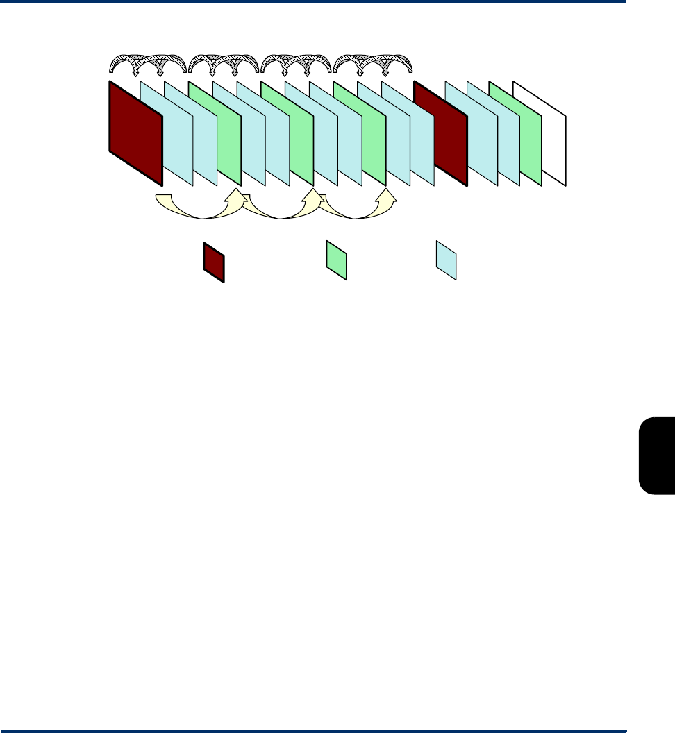
GOP types
For any video stream, a set of frames is called a group of pictures or GOP, with the specific sequence
known as the GOP structure. A common GOP structure would include one I-frame, followed by two B-
frames, then followed by one P-frame, and so on, represented as “IBBPBBP…" The following figure
represents a simplified diagram of frame reference and interpolation, using a typical GOP structure:
Preliminary issue - Limited distribution only!
Tech-X Flex® (NG2) Tech-X Flex User Guide - Firmware v06.50
6-41
Intro
Overview
Wi-Fi
Ethernet
System
IP/Video
MoCA
RF
Specs
Figure 6-20 Compressed video stream frames
Audio compression
Audio compression has some similarity to video compression, in that techniques may be used to
eliminate redundant data. Furthermore, audio exhibits the concept of “masking,” where one frequency
may mask another and the human ear is unable to perceive it. Because it is unnecessary to transmit any
data for sounds that will never be heard, the removal of this data from the original audio stream provides
further possibilities for data reduction.
Additional details of encoding, decoding, and compression algorithms are complex and beyond the
scope of this document.
About MPEG transport
The MPEG standards refer broadly to a set of protocols for transporting compressed audio/video
programs over a communications network, such that a decoder can properly reconstruct the audio/video
programs at the destination. It is overseen by the Moving Picture Experts Group
(http://www.chiariglione.org/mpeg/).
A fundamental concept of MPEG transport is the “program,” the higher-level entity that end users receive
when they select a “channel.” Fully-decoded, an MPEG program is the entire dataset required to present
a single multimedia experience to the user, such as the complete and synchronized audio/video streams
required to watch a single IPTV channel.
The preparation of the audio/video programs has two fundamental stages:
I frames P frames B frames
Preliminary issue - Limited distribution only!

Tech-X Flex User Guide - Firmware v06.50 Tech-X Flex® (NG2)
6-42
Intro Overview Wi-Fi Ethernet System IP/Video MoCA RF Specs
•Elementary stream - The elementary stream is the basic compressed audio or video bitstream. In
the case of a video stream, this is the original content segmented into macroblocks, slices, and
frames, then packetized with header information required to reconstruct the stream at the far end. An
elementary stream is a single stream of video or audio only, relying on the transport stream layer to
associate it with other streams and create the concept of a program.
•Transport stream - Once constructed, one or more elementary streams are packetized into a
transport stream that provides all the instructions necessary to identify the data associated with a full
program, synchronize with the encoder, and reconstruct and present the audio/video program
properly. The transport stream includes the program clock reference or PCR, which provides the
critical data required for the decoder to synchronize its internal clock with that of the encoder. Without
synchronization, the decoder would be unable to recreate the video with the same timing as it was
encoded. Furthermore, the transport stream includes information such as:
–Packet identifiers or PIDs - Used as unique identifiers for individual elementary streams, as well
as program-specific information as described below.
–Program map table or PMT - Lists the elementary streams in the transport stream and identifies
the respective program(s) to which they belong. A program includes one or more elementary
streams, typically one video elementary stream and one or more audio elementary streams.
–Program association table or PAT - Lists all the programs included in the transport stream, as a
high-level list of all programs available to the decoder (or in other words, channels available to the
end user). When a program is selected for decoding, the decoder uses the program identifier in
the PAT to look up the required streams in the PMT.
–Conditional access table or CAT - Includes pointers to the PIDs that contain the entitlement
control/management messages needed to unscramble audio/video content, useful for
subscription-based services where access is limited.
Once completed, a transport stream is a sequence of 188-byte MPEG packets, ready for encapsulation
and transport over a communications network. The header data of transport streams, as well as that of
packetized elementary streams, is extremely useful for performing audio/video quality analysis, and
therefore provides the great majority of data used to calculate quality scores and other metrics.
With respect to degradation that may be caused during transport, the impact on audio/video quality
depends heavily upon the specific portion of the transport stream that is affected. For example, at the
lowest level, a loss of macroblock data may only cause a momentary anomaly in the display, perhaps not
even perceptible by the viewer. At the other extreme, a loss of MPEG transport header data, such as a
loss of synchronization, can cause the complete loss of the video altogether. For this reason, modern
analysis techniques must carefully consider the nature of loss and its respective impact on quality.
Overall, it should be noted that the descriptions here are highly-simplified, provided as a general
overview only. The full architecture of a complete MPEG transport stream is multi-layered and very
complex, beyond the scope of this document to describe.
Preliminary issue - Limited distribution only!
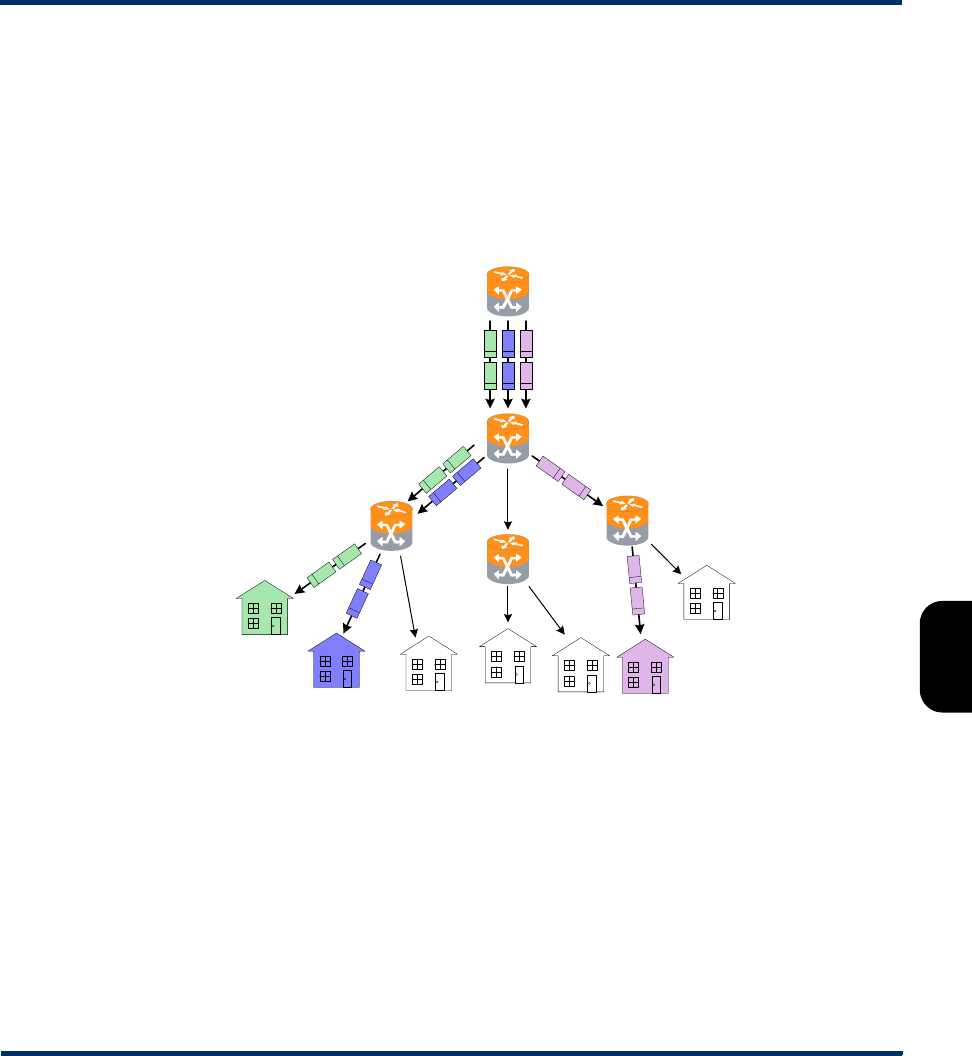
Tech-X Flex® (NG2) Tech-X Flex User Guide - Firmware v06.50
6-43
Intro
Overview
Wi-Fi
Ethernet
System
IP/Video
MoCA
RF
Specs
About IP multicast
IP multicast is a set of protocols that allows a single IP packet to be sent to multiple hosts (that is, “group
members”) without the need to send multiple redundant copies of the same packet from the source. It
serves to alleviate network congestion when multiple hosts need to receive the same traffic, such as the
case where multiple IPTV subscribers are watching the same channel and each will ultimately receive
the exact same data payload.
Consider the following diagram, which represents a small network without multicasting:
Figure 6-21 Hypothetical network without group multicasting
In the previous figure, three subscribers are watching the same channel. The shaded packets represent
the unicast IP streams required to deliver the service. The IP payload in each stream, however, is exactly
the same, resulting in a redundancy that creates congestion and scalability issues.
Alternatively, consider the following figure, which illustrates group multicasting:
R2
R3
R1
R4
R5
Preliminary issue - Limited distribution only!
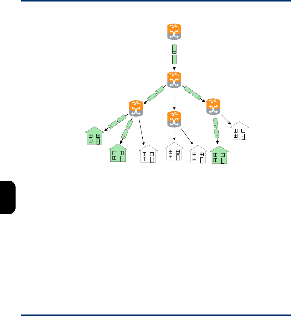
Tech-X Flex User Guide - Firmware v06.50 Tech-X Flex® (NG2)
6-44
Intro Overview Wi-Fi Ethernet System IP/Video MoCA RF Specs
Figure 6-22 Hypothetical multicast network with multicasting and IGMP
In this example, the routers are multicast-aware and can make intelligent decisions about packet
forwarding. The routers control the forwarding of multicast packets, with those routers directly connected
to multicast group members using Internet Group Management Protocol (IGMP) to manage the
duplication and forwarding of packets to individual group members.
In a multicast-enabled network, multicast routers interact and dynamically maintain a logical tree for
routing multicast packets, in order to efficiently deliver the required packets to each subnet that requests
them. If no subscribers on a particular subnet are members of a given multicast group (for example, no
one on a particular subnet is viewing a particular audio/video stream), the network may automatically
adjust to avoid multicasting that stream to that subnet. Similarly, when a host on a subnet successfully
joins a group, the network will dynamically extend a branch of the respective multicast tree to the router
serving the host. In summary, therefore, multicasting improves transport efficiency both by eliminating
redundant packets from the same media source, and by eliminating the indiscriminate broadcast of any
packets to branches in the network that have no hosts requesting them.
Note that multicasting is a form of “selective broadcasting,” where packets from the source are simply
duplicated as necessary and forwarded onto the respective links, all the way down the multicast tree to
each requesting group member. IP multicast routers use specialized multicast routing protocols such as
R2
R3
R1
R4
R5
Preliminary issue - Limited distribution only!

Tech-X Flex® (NG2) Tech-X Flex User Guide - Firmware v06.50
6-45
Intro
Overview
Wi-Fi
Ethernet
System
IP/Video
MoCA
RF
Specs
Protocol Independent Multicast (PIM) to build logical multicast trees and forward packets efficiently
between the multicast source and group members. Once multicast packets reach their destination
subnets, group members "listening" for packets with the specific IP multicast (destination) address will
receive and process the packets accordingly.
The IP address range of 224.0.0.0 - 239.255.255.255 is reserved for multicast packets. It should be
noted that these addresses are likely unroutable in a traditional sense on the destination subnets that
receive the packets. Rather, it is the suite of multicasting protocols that allows packets to be properly
forwarded and ultimately processed by the proper group member device(s). This is distinctly different
from unicast transmission, where IP packets are addressed for a specific source/destination pair and
exchanged exclusively between the two hosts.
Video quality measurement (VQM) overview and additional results descriptions
The following sections describe the quality measurement process in more detail, for the “VQM” mode of
analysis. For more information on MDI, see MDI measurement overview on page 6-48.
How the analysis works - An overview
The following metrics may be used to estimate the overall subjective quality of the audio/video stream,
some of which are also reported in the results:
•Audio/video packet details - Comprehensive metrics describing the number of MPEG packets
received, lost, and discarded.
•General audio/video stream information - Stream characteristics such as audio/video codec,
audio/video stream bit rate, video stream GOP size/structure, and video stream image size.
•Degradation factors - Identification and quantification of the factors which have caused degradation
of the video signal, such as codec, packet loss, and packets discarded due to buffer underrun and/or
overrun.
•General network metrics - Information on the overall packet transport network such as packet delay
variation and packet loss.
Quality is estimated based on general stream, packet, and frame characteristics that are known to have
a predictable impact on user experience. This methodology provides reliable measurements without the
need to decrypt a scrambled video signal. Packet loss is naturally the primary factor involved with
audio/video quality degradation, but the following types of considerations also affect quality calculations:
• Other problems related to network impairments, such as packet delay variation and out-of-sequence
packets.
• The inherent abilities of the codec and associated equipment to conceal network impairments such
as packet loss.
Preliminary issue - Limited distribution only!

Tech-X Flex User Guide - Firmware v06.50 Tech-X Flex® (NG2)
6-46
Intro Overview Wi-Fi Ethernet System IP/Video MoCA RF Specs
• The structure and length of GOPs (MPEG Groups of Pictures), especially with regards to the varied
effects of packet loss on different frame types.
• The bit rate and frame size (or resolution) used at the encoder, as smaller rates and lower resolutions
can degrade the quality of the image even if transport is flawless.
• The impact of recency. Recency is the trend of human viewers to judge audio/video quality to be
lower immediately following a disturbance to the signal, and the subsequent trend for that perception
to improve gradually if time passes with no further disturbance.
• Packet loss distribution. Bursty packet loss events in which consecutive packets are dropped have a
different effect on perceived audio/video quality than packet loss events in which single packets are
dropped and the time (or “distance”) between the single loss events is significant.
• Loss of synchronization between the audio and video signals.
While it does not measure signal-to-noise directly, the analysis does use codec and packet loss/discard
information to calculate an estimated peak signal/noise ratio (EPSNR). The EPSNR is then used as a
key input for quality score calculations.
About MOS and R-factor calculations
MOS (mean opinion score) is a numerical system used to grade the subjective perceptual quality of a
multimedia (audio, video, or both) user experience. Originally based on ITU-T recommendations for the
evaluation of voice quality, it uses a scale of 1 - 5 to indicate user experience with the following typical
benchmarks:
MOS scoring is frequently produced by software algorithms that monitor multimedia streams and attempt
to “emulate” a subjective user experience. Such software is intended to produce results that are similar to
MOS scores that would be recorded by actual human participants consuming and evaluating the media.
Score Quality Human perception of degradation
5Excellent Imperceptible. No degradation of quality can be detected
by a human subject.
4Good Perceptible. Degradation can detected, but does not
adversely impact the user experience.
3Fair Slightly annoying
2Poor Annoying
1Bad Very annoying or no data stream present
Preliminary issue - Limited distribution only!

Tech-X Flex® (NG2) Tech-X Flex User Guide - Firmware v06.50
6-47
Intro
Overview
Wi-Fi
Ethernet
System
IP/Video
MoCA
RF
Specs
The R-factor is a similar concept and is actually the mathematical component by which a MOS is
estimated. It is calculated using what is known as the “E-model” formula. This formula involves a
subjective summation of impairment and “advantage” factors, including the typical packet network
parameters such as jitter, latency, and loss. Like the MOS score, the higher the number, the better. An R-
factor result is presented as a percentage, where 80% loosely corresponds with an MOS score of 4, and
a factor of 50% corresponds with an MOS of 2.6.
While these types of measurement may help you view a snapshot summary of network quality, you
should remember that “real,” quantifiable network conditions are the only reliable means of judging
network integrity. Any means of numerically calculating the quality of the human experience is
necessarily subjective.
About gap and burst states
The software models the distribution of packet loss over the measurement duration, which allows for a
more detailed characterization of the packet loss experienced by the audio/video stream. This is a four-
state model in which two periods of loss exist, gap and burst periods, each of which has two states.
The stream is considered to be in a gap condition of loss when consecutive packet loss is less than or
equal to one packet. If two or more consecutive packets are lost, the stream is considered to be in a burst
condition. Following the entry into a burst period, 128 consecutive packets must be received in order to
return to the gap condition, a number determined though research of quality measurements. Note that
the successfully received packets will be considered to have arrived during a gap period.
Other test results
About packet delay variation (PDV)
Packet delay variation is a calculation based on the variation of a packet’s expected arrival time versus
its actual arrival time. Each packet has its own PDV, which is determined by:
| Expected time - Arrival time |
...noting the use of absolute values. So, if a packet is expected to arrive at time1 but actually arrives at
time2, it has a PDV of | time1 - time2 |. Typically, individual PDVs are used for calculating an average for
multiple packets in a stream, or reporting the maximum PDV experienced during a measurement period.
NOTE: Packet delay variation is sometimes referred to as jitter. However, the use of PDV terminology
is preferred in this documentation due to its more specific definition.
Preliminary issue - Limited distribution only!

Tech-X Flex User Guide - Firmware v06.50 Tech-X Flex® (NG2)
6-48
Intro Overview Wi-Fi Ethernet System IP/Video MoCA RF Specs
About packet-to-packet delay variation (PPDV)
Packet-to-packet delay variation (PPDV) is a statistical calculation of delay variation, based on the
method described by the IETF RFC 3550. It differs from basic packet delay variation (PDV) which looks
at variations in arrival time overall, not necessarily variations between adjacent, sequential packets.
As an example, consider four sequential packets, whose delays in arrival are 40, 42, 38, and 39 msec
respectively. The delay variation of the second packet is 2 msec ( | 40 - 42 | ), the delay variation of the
third packet is 4 msec, and so forth. The measurements continue for all selected packets in the
measurement stream, with all measurements considered in the end for a calculation of statistical
variance.
Note that the usage of PDV versus PPDV is a complex subject and is beyond the scope of this
document.
MDI measurement overview
Media delivery index (MDI), defined by IETF RFC 4445
(http://www.ietf.org/rfc/rfc4445.txt?number=4445), is a technique for evaluating the quality of media
delivered over a packet-based network, including MPEG video. It focuses on the evaluation of delay
variation and packet loss, which are the primary network impairments that impact the delivery of
audio/video and other time-sensitive streaming media. In this respect, it is a packet-level, network-
focused type of evaluation, different from the type of subjective quality analysis that monitors stream
headers for specific transport characteristics. MDI may be used to evaluate voice, video, and other types
of streaming media.
An MDI result consists of two components: the Media Loss Rate (MLR) and the Delay Factor (DF),
typically presented as:
MLR:DF
Before analysis begins, the unit monitors the transport stream to determine the nominal media rate using
the Program Clock Reference (PCR). The unit then monitors the transport stream for the entire testing
interval to determine MLR and DF for that interval.
The MLR is the count of lost or out-of-order media packets over the measurement interval. Every MPEG
transport packet is counted, except for null packets (PID 0x1FFF) or packets with no payload. Note that a
single IP packet may contain multiple media packets, so a single IP packet loss event may cause a
significantly higher media loss.
Because the analysis is not coordinated with the encoding source, the unit cannot know what media
packets were actually sent. Therefore, it must determine lost packets using PID and continuity counter
values from transport stream headers. That is, when a packet arrives, lost packets can be interpolated
based on discrepancies between the current continuity counter and previous arrivals. Due to this method,
Preliminary issue - Limited distribution only!

Tech-X Flex® (NG2) Tech-X Flex User Guide - Firmware v06.50
6-49
Intro
Overview
Wi-Fi
Ethernet
System
IP/Video
MoCA
RF
Specs
measured loss is only accurate when consecutive loss events are smaller than the capacity of the
continuity counter, which is 0-15 (4 bits). In other words, the maximum amount of measurable
consecutive loss is 15 packets. Also, note that a packet with an errored sync byte or a transport error
indicator set will be discarded and considered lost for the purpose of this measurement.
The unit also uses continuity counter values to determine out-of-order packets and the counter range of
0-15 provides a related accuracy limitation. The basic unit behavior is to consider any late packet that
arrives within 7 packets of expected order as out-of-order, otherwise it is considered to be a member of
the next counter “set.” This behavior is best illustrated by an example, as follows...
Assume that all packets are arriving as expected, when packet 2 of a counter set goes missing (that is,
packet 3 arrives after packet 1). At that point, packet 2 is initially considered lost. If packet 2 finally arrives
sometime before packet 9, its status changes to out-of-order and the respective cumulative counts are
adjusted accordingly. However, consider instead a scenario where packet 2 arrives after packet 10. In
this case, the original packet 2 is considered permanently lost and the packet that arrives is considered
to be packet 2 of the next set, at which point the originally-expected packets 11, 12, 13, 14, 15, 0, and 1
are initially considered lost. If these packets then arrive normally, their status changes to out-of-order and
the respective counts are adjusted accordingly. When the “real” packet 2 arrives for the next set, the unit
has two “packet 2’s” in the buffer and must assume that the original packet 2 is out-of-order for some
unknown previous set, so it increments the out-of-order count again and resets the algorithm. In this
scenario, a single late packet has caused the lost count to increment by one and the out-of-order count to
increment by 8.
The DF, presented as a quantity of time, is the maximum observed imbalance in stream flow over the
measurement interval, with respect to the expected media payload rate. That is, it effectively reports how
much buffering would be required to fully compensate for network delay variation at the respective node.
As such, it also indicates the amount of latency that must be introduced in order to properly decode the
stream. To calculate the DF, the software uses a “virtual buffer” concept, using the ingress of packets
versus the expected “drain” rate (that is, the media rate) to determine the variance. In some respects, the
DF provides a high-level view of the delay variation experienced by packets transiting from source to
destination. It may be useful to quantify the performance of the audio/video streams and transport
network over time and to adjust equipment buffers accordingly.
For convenience, Spirent has implemented a proprietary algorithm to convert MLR and DF calculations
into a score that resembles a mean opinion score (MOS), as defined by the ITU-T. This scoring method,
referred to as “MDI-S,” uses a scale of 1 - 5 to indicate perceived viewer experience with the following
typical benchmarks:
Score Quality Human perception of degradation
5Excellent Imperceptible. No degradation of video quality can be
detected by a human viewer.
Preliminary issue - Limited distribution only!

Tech-X Flex User Guide - Firmware v06.50 Tech-X Flex® (NG2)
6-50
Intro Overview Wi-Fi Ethernet System IP/Video MoCA RF Specs
Additional video testing notes
About the IP address specified for testing
The IP address specified must reflect the destination IP address for video stream packets; that is, the first
address contained in the IP packet headers. For a multicast stream, this will be a multicast IP address,
not an IP address of a host on the network under test. For a unicast stream, this must be the IP address
of the destination device on the network, such as a set-top box (STB).
About encrypted (scrambled) signals and frame type recognition
The analysis software does not perform any decryption of scrambled signals. For monitoring a scrambled
stream, this can affect the ability to recognize frame types because the type indicator data may be
encrypted as well. Because perceived effect of packet loss varies widely according to the type of frame
whose data was lost, the frame type is an important component when packet loss is evaluated. Therefore
the software exhibits the following behavior with regards to frame type recognition:
• If the signal is not scrambled, the software should be able to recognize frame types according to
explicit data in the stream and precisely associate lost packets with the respective type.
• If frame type data is encrypted but frame boundaries can be discerned, the software heuristically
attempts to determine frame type based on relative data size and expected patterns.
• If frames cannot determined at all, the software uses default GOP structure and length information
specified when the analysis is launched to interpolate the probabilities of packet loss occurring within
any given frame type. Over time, if the defaults accurately reflect the GOP setup of the stream, the
measurements and estimations should be statistically correct.
While the lack of decryption by the software may appear initially as a limitation, it actually provides much
more flexibility with deployment and ease of maintenance. With the ability to interpolate encrypted frame
types, users are not required to maintain and deploy decryption algorithms that require processing time,
change periodically, and may be expensive and/or difficult to license.
4Good Perceptible. Degradation can detected, but does not
adversely impact the viewing experience.
3Fair Slightly annoying
2Poor Annoying
1Bad Very annoying or no stream present
Score Quality Human perception of degradation
Preliminary issue - Limited distribution only!
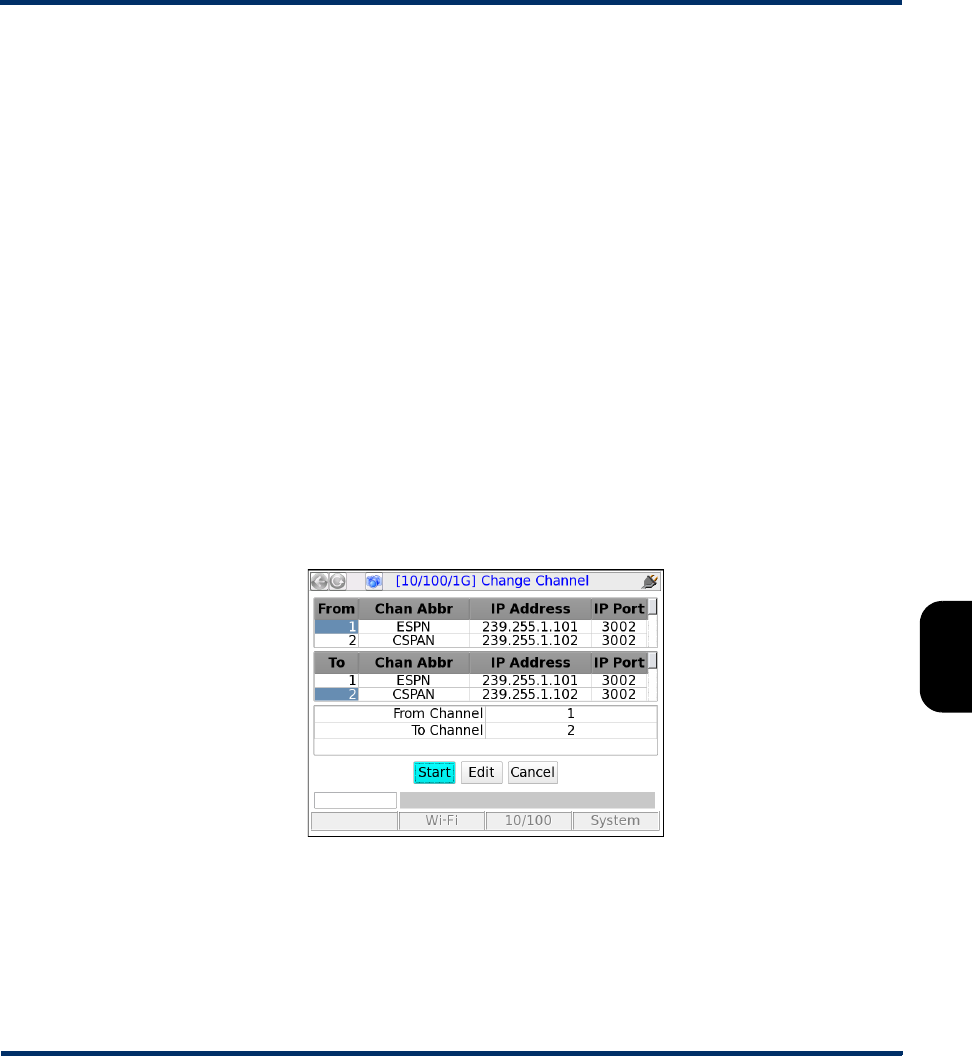
Tech-X Flex® (NG2) Tech-X Flex User Guide - Firmware v06.50
6-51
Intro
Overview
Wi-Fi
Ethernet
System
IP/Video
MoCA
RF
Specs
6.11.2 Change Channel
NOTE: Video testing is a purchasable option. Please contact Spirent for more information.
The IPTV change channel test measures channel change time by measuring the time between IGMP
requests and resulting changes in the packet stream. The unit accomplishes this measurement by joining
a multicast stream and initiating an actual channel change, emulating the behavior of IPTV subscriber
STB equipment.
For more detailed information on the time calculation, see How channel change time is calculated on
page 6-52.
Setup - Change Channel
The Change Channel setup differs whether or not a channel guide is active. For more information on
channel guides, see About channel guides on page 6-53.
With an active channel guide:
The unit presents a table with which you can select the two channels for the test. All other required
information is prepopulated from the channel guide, such as IP addresses and port numbers. For more
information on how the channels are used, see How channel change time is calculated on page 6-52.
Figure 6-23 Change Channel setup - Page 1 (with channel guide)
NOTE: The screen has a small display area and can only show a limited number of channels from the
guide at once. Remember to use the scroll bars on the table and/or the arrow keys on the key
pad to locate the desired channels. Furthermore, be sure that the From Channel and To
Channel at the bottom accurately reflect the channels you want to test.
Preliminary issue - Limited distribution only!
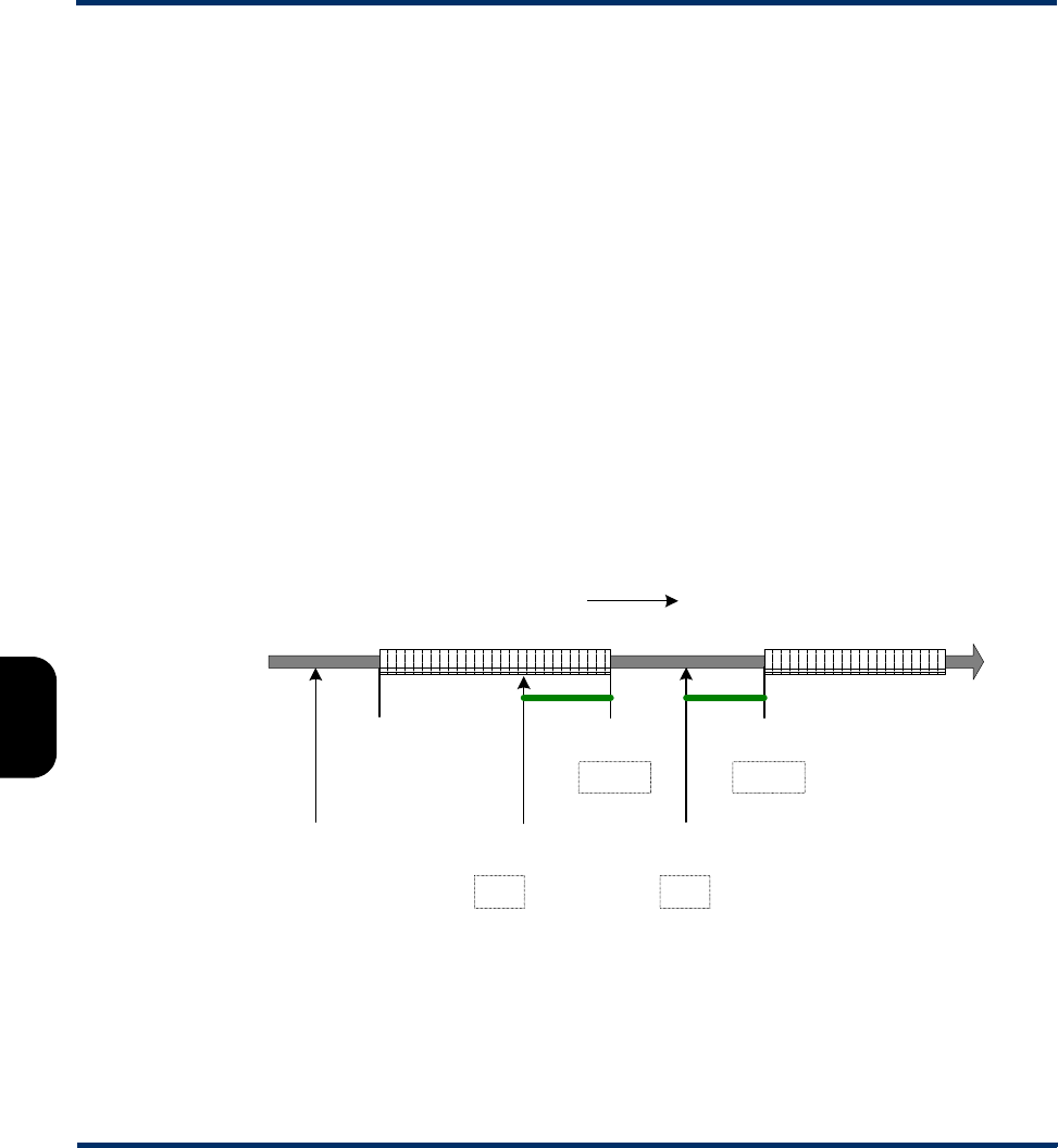
Tech-X Flex User Guide - Firmware v06.50 Tech-X Flex® (NG2)
6-52
Intro Overview Wi-Fi Ethernet System IP/Video MoCA RF Specs
Without an active channel guide:
The unit requires you to manually enter the following information for each channel:
•IP Address - IP address of the multicast stream
•IP Port - UDP or TCP port of the stream, with respect to the Encapsulation Method
•Encapsulation Method - Transport encapsulation used for the stream
•Codec - Video codec type
Results - Change Channel
The test reports the channel change time in msec, along with other parameters used in the calculation.
For more information, see How channel change time is calculated on page 6-52.
How channel change time is calculated
During a channel change test, the unit joins the first specified channel, leaves that channel, and then
joins the second specified channel. During this process, four key events are used for the change time
calculation, as illustrated in the following figure:
Figure 6-24 Channel change calculation timeline
Referring to this figure, if no time periods overlap, the basic formula for change time calculation is:
Time = (LastA - ML) + (FirstB - MJ)
ML
Multicast join
request - Ch. A
First packet -
Ch. A
Multicast leave
request - Ch. A
Last packet -
Ch. A
Multicast join
request - Ch. B
First packet -
Ch. B
LastA
MJ
FirstB
Time
Channel A stream Channel B stream
Preliminary issue - Limited distribution only!

Tech-X Flex® (NG2) Tech-X Flex User Guide - Firmware v06.50
6-53
Intro
Overview
Wi-Fi
Ethernet
System
IP/Video
MoCA
RF
Specs
In these calculations, the individual terms are instances in time, not quantitative amounts of time. In other
words, channel change time equals time it takes to leave the first stream plus the time it takes to join the
second stream, measured from the respective IGMP requests.
For reference, the unit indicates the following test results:
•Leave to Last Time - Equals the (LastA - ML) term.
•Join To First Time - Equals the (FirstB - MJ) term.
6.11.3 Channel Guide Settings
This function allows you to configure the unit for channel guide usage. It is available from multiple menus
associated with active Video QoS testing, but the settings are global to all interfaces. For example, you
can access and configure these settings from the 10/100/1G menu, but all changes will also apply to
video testing on other interfaces, such as the modular MoCA interface. For more information about
channel guides, see About channel guides on page 6-53.
Table 6-25 Channel Guide Settings parameters
About channel guides
A channel guide provides a shortcut for specifying IP video channels during video testing of multicast
streams. When the unit joins and/or monitors a video stream for testing, it requires the IP address and
port of that stream. If you do not have an active channel guide on the unit, you must enter the address
and port manually. However, if you do have an active channel guide that includes the respective channel,
it allows you to select a simple channel number or a more intuitive channel abbreviation, such as CNN or
HBO. The unit then looks up the address and port in the guide instead of requiring a manual entry. A
Parameters Description
Use Channel Guide Indicates whether a channel guide is currently active for video test setup. For
more information, see About channel guides on page 6-53.
Guide Name Name of the active channel guide, only applicable when Use Channel
Guide=Yes. The drop-down list allows you to select from the guides currently on
the unit, if any. If the list is blank, no channel guides have been imported. For
more information, see About channel guides on page 6-53 and Download IPTV
Channel Guide on page 5-8.
Channel Format If Use Channel Guide=Yes, this setting determines how channels from the
guide are initially sorted in a video test setup screen, either by number or
abbreviation. In either case, the number or abbreviation comes directly from the
guide.
Preliminary issue - Limited distribution only!

Tech-X Flex User Guide - Firmware v06.50 Tech-X Flex® (NG2)
6-54
Intro Overview Wi-Fi Ethernet System IP/Video MoCA RF Specs
channel guide also provides a series of other default testing parameters for each channel, such codec
type and media stream information.
NOTE: The channel guide concept does not apply to unicast video. With unicast, the destination IP
address for video packets will be that of the endpoint device (such as an STB), rather than a
predictable multicast address. Therefore, it is not possible to standardize unicast IP information
within a channel guide.
Channel guides are in XML format and must adhere exactly to the format in the following sample (except
for the <!-- comments -->), with regard to tag names, case-sensitivity, and element hierarchy:
<video-channel-info>
<!-- Each channel is defined by a single <channel-info> element -->
<channel-info>
<!-- Channel number, an integer -->
<channel-number>001</channel-number>
<!-- Channel abbreviation, a string -->
<channel-abbreviation>ESPN</channel-abbreviation>
<!-- IP address of the channel stream in xxx.xxx.xxx.xxx format -->
<IP-address>239.255.1.101</IP-address>
<!-- UDP port of the stream, an integer -->
<IP-port>3002</IP-port>
<!-- Encapsulation type, UDP or RTP -->
<encapsulation>UDP</encapsulation>
<!-- Codec, H264, MPEG2, MPEG4, or NA -->
<codec>MPEG2</codec>
<!-- Jitter buffer mode, FIXED or ADAPTIVE -->
<jitter-mode>FIXED</jitter-mode>
<!-- GOP type, GOP_A, GOP_B, GOP_C, GOP_D, or GOP_E -->
<gop-type>GOP_C</gop-type>
<!-- GOP length, 1 - 100 -->
<gop-length>15</gop-length>
<!-- Loss sensitivity, -50 - 50 -->
<loss-sensitivity>0</loss-sensitivity>
<!-- Concealment level, 0 - 50 -->
<packet-loss-concealment-level>2</packet-loss-concealment-level>
<!-- Complexity (content coding factor), -50 - 50 -->
<image-complexity>0</image-complexity>
</channel-info>
<!-- ...additional <channel-info> elements, one for each channel -->
</video-channel-info>
Preliminary issue - Limited distribution only!

Tech-X Flex® (NG2) Tech-X Flex User Guide - Firmware v06.50
6-55
Intro
Overview
Wi-Fi
Ethernet
System
IP/Video
MoCA
RF
Specs
The element names intuitively denote each respective parameter and the comments in the sample above
provide some description of valid values. To ensure that a channel guide conforms to the required
syntax, please contact Spirent for the latest XML schema and use it to validate your file(s).
Importing channel guides to the unit
See Download IPTV Channel Guide on page 5-8
6.12 Packet Capture
Packet Capture provides a basic packet capture utility, where traffic on an interface is recorded in PCAP
format, then the PCAP file can be transferred from the unit for further analysis. This feature may be
especially useful for VoD troubleshooting, as a capture can used to analyze the IGMP activity on the
network.
6.12.1 Packet Capture setup and launch
Packet Capture requires the unit to be established as a traffic bridge, one of:
•Ethernet-to-Ethernet - Two cables are connected at the 10/100/1G interface, where the internal
switch is inherently bridging some traffic flow.
•MoCA-to-MoCA - The unit is connected in standard MoCA “inline” mode (see Join MoCA Network
In-Line (Bridging and passive testing) on page 7-19.
•MoCA-to-Ethernet - The unit is connected in MoCA “ECB” mode (see About MoCA and 10/100/1G
interface bridging (ECB) on page 7-23.
The command to launch a capture is located in the VOD Scoring menu, which itself is located in the IP
testing area for the respective interface (for example, 10/100/1G > VOD Scoring > Packet Capture.
NOTE: Where applicable, capture data is retrieved from the WAN interface of the connection.
The Packet Capture setup includes the following parameters:
Preliminary issue - Limited distribution only!

Tech-X Flex User Guide - Firmware v06.50 Tech-X Flex® (NG2)
6-56
Intro Overview Wi-Fi Ethernet System IP/Video MoCA RF Specs
Table 6-26 Packet Capture - Setup
Parameter Description
Max Test Duration Maximum length of time to run the capture, in seconds. The actual time
may be shorter if:
• The maximum number of frames have been captured, or
• The maximum capture file size is met (100 MBytes), or
• The test is stopped while in progress.
In all cases, a capture file is still produced for the length of time that the
capture ran.
Filter Expression Optional expression to filter traffic for the capture. The expression should
use the “standard” PCAP format, described in detail at the following site:
http://www.tcpdump.org/manpages/pcap-filter.7.html
Note that this syntax may be complex and requires some expertise to
apply properly.
File Name Case-sensitive PCAP filename (minus the extension) that will appear in
the Record Manager for upload, following the capture. The PCAP
extension is appended automatically.
Store pkt Length Maximum amount of each packet (Ethernet frame) to include in the
capture, in bytes. Specify 0 (zero) to store every frame in its entirety. The
overall valid range is 0 - 1499.
Frame Count Maximum number of Ethernet frames to capture, after which the test
stops automatically, where 0 indicates no limit. The overall valid range is
0 - 65535.
Preliminary issue - Limited distribution only!
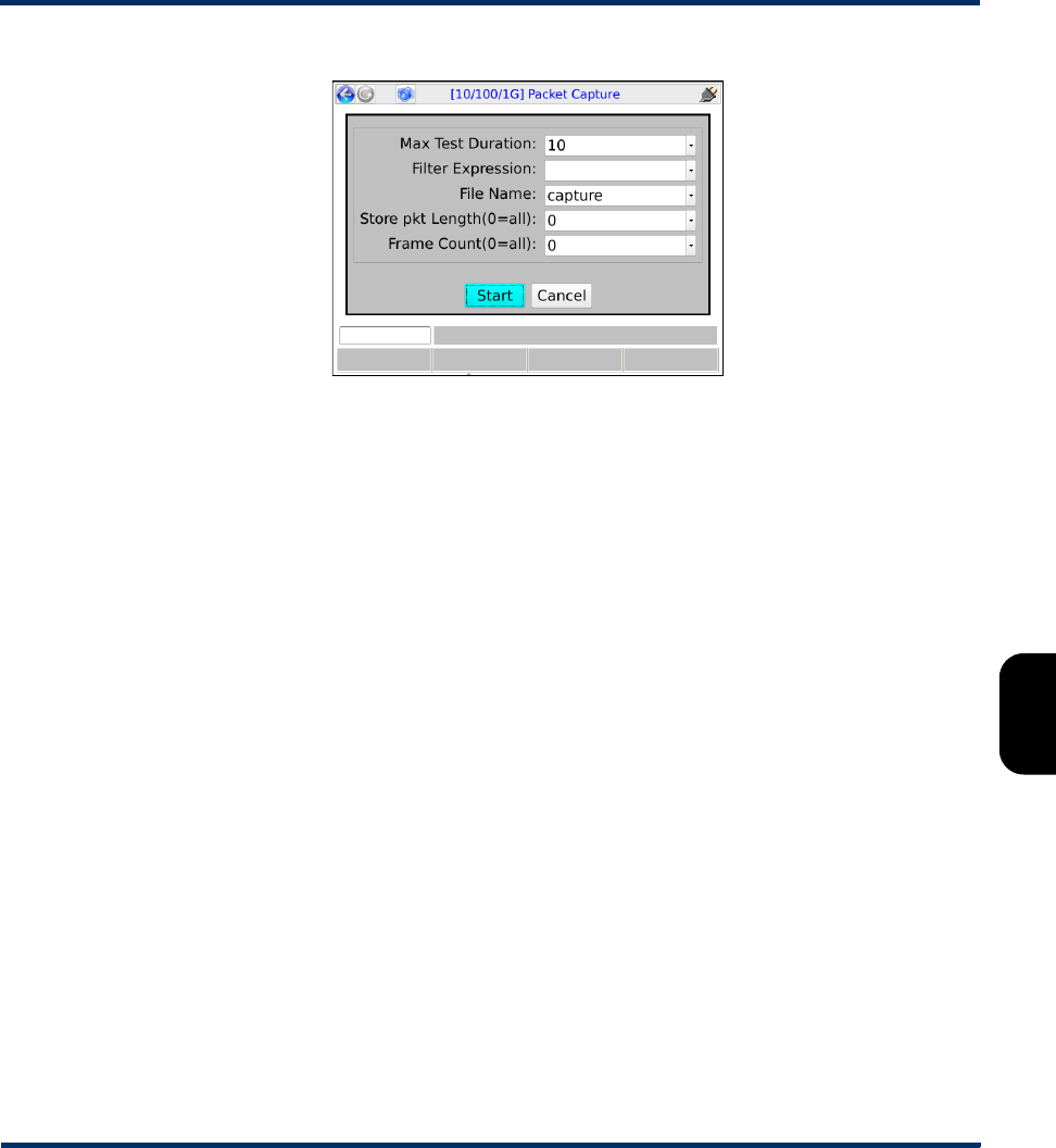
Tech-X Flex® (NG2) Tech-X Flex User Guide - Firmware v06.50
6-57
Intro
Overview
Wi-Fi
Ethernet
System
IP/Video
MoCA
RF
Specs
Figure 6-25 Packet Capture - Setup
6.12.2 Packet Capture results and PCAP file upload
Results include basic statistics about the amount of data captured. Afterwards, the capture file is
available for upload using standard Record Manager tools (see Record Manager > Upload Files on
page 5-4).
Preliminary issue - Limited distribution only!

Tech-X Flex User Guide - Firmware v06.50 Tech-X Flex® (NG2)
6-58
Intro Overview Wi-Fi Ethernet System IP/Video MoCA RF Specs
Preliminary issue - Limited distribution only!
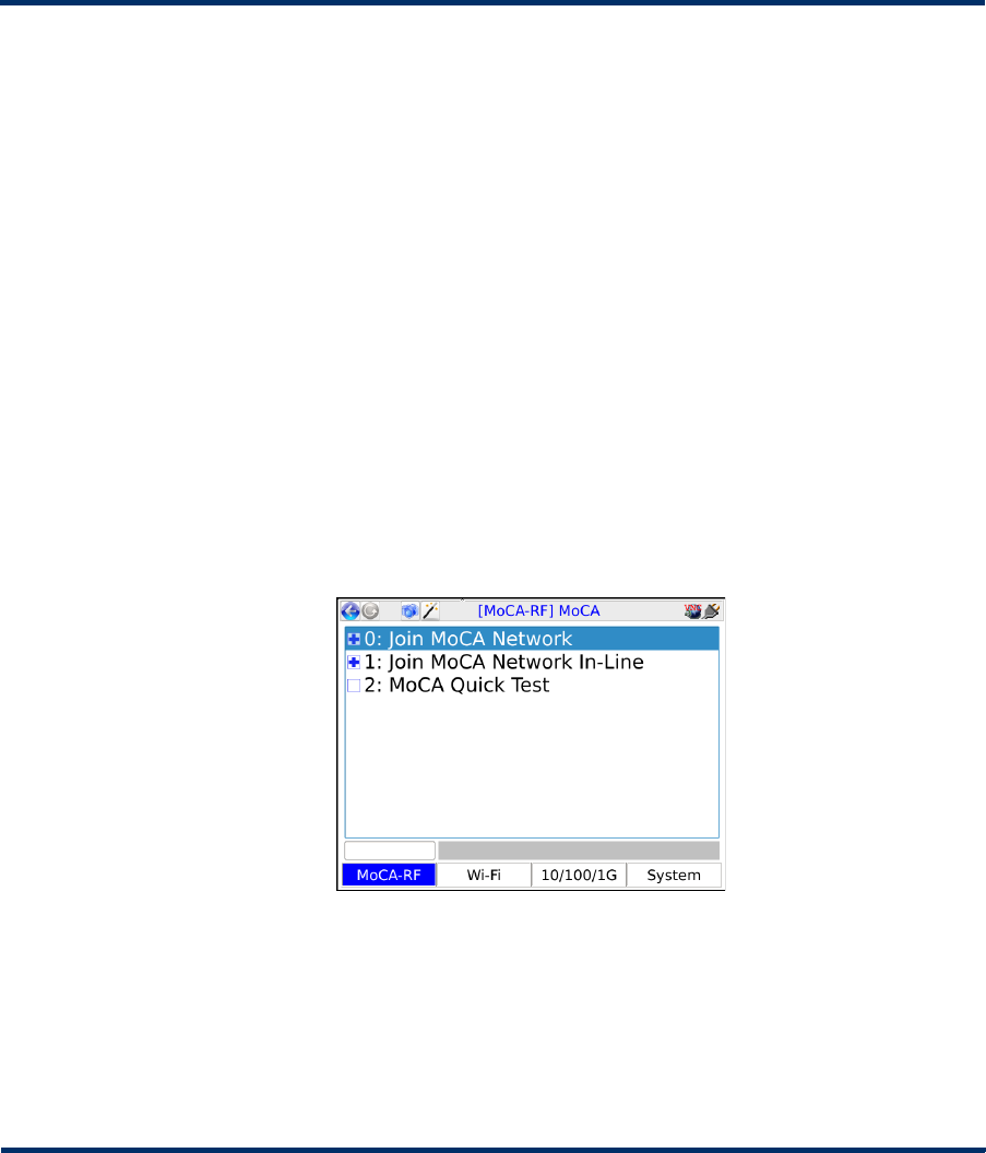
Tech-X Flex® (NG2) Tech-X Flex User Guide - Firmware v06.50
7-1
7: MoCA/RF - MoCA Testing
This section describes the MoCA-specific functions of the combined MoCA/RF module. The unit
supports synchronization with MoCA standards 1.0, 1.1, and 2.0, with full backwards-compatibility
behaviors as dictated by the respective standards. For a brief overview, see Overview of testing
capabilities and setup on page 7-2.
For more information on specific functions, see:
•Join MoCA Network (Single-ended testing details) on page 7-4
•Join MoCA Network In-Line (Bridging and passive testing) on page 7-19
•MoCA Quick Test on page 7-23
Figure 7-1 MoCA main testing menu
7.1 Important notes on handling the module
See Handling the MoCA/RF module on page 2-30.
Preliminary issue - Limited distribution only!

Tech-X Flex User Guide - Firmware v06.50 Tech-X Flex® (NG2)
7-2
Intro Overview Wi-Fi Ethernet System IP/Video MoCA RF Specs
7.2 Overview of testing capabilities and setup
The MoCA module allows the unit to join a MoCA network on a specified channel. After joining the
network, the unit can perform functions such as:
• Retrieval of statistics about itself and other nodes on the network, including the bandwidth between
nodes.
• IP address assignment and basic connectivity tests such as ping and traceroute.
• Video testing, both by actively joining a multicast stream and by passively monitoring an existing
stream.
There are two basic physical setups for the unit:
•Single-ended - A single cable terminated at the unit, where the unit is intended to join the network
similar to any other node and perform stats retrieval and active testing functions (see Join MoCA
Network (Single-ended testing details) on page 7-4)
•Bridged - Two cables terminated at the unit, where the unit is “bridging” a MoCA connection and can
passively monitor traffic, as well as perform active testing in either direction (see Join MoCA Network
In-Line (Bridging and passive testing) on page 7-19)
7.2.1 Testing scenarios
The following table describes certain issues that a technician might encounter, along with suggestions for
how to use the unit for troubleshooting. Your use of the unit may vary according to field conditions and
applicable protocol.
Preliminary issue - Limited distribution only!

Tech-X Flex® (NG2) Tech-X Flex User Guide - Firmware v06.50
7-3
Intro
Overview
Wi-Fi
Ethernet
System
IP/Video
MoCA
RF
Specs
Issue Troubleshooting suggestions
One TV (using
IPTV) in the home
has a poor and/or
intermittent
picture, or no
picture at all
The primary use of the unit is to confirm or rule out the STB as the cause.
Troubleshooting might proceed as follows:
1. Disconnect the cable from the STB, connect the unit directly to the STB, and
attempt a single-ended MoCA synchronization on the LAN channel. This action
effectively creates a small, independent MoCA network between the unit and
the STB. The STB can be considered suspect if:
• If the unit cannot synchronize at all
• MoCA stats show poor bandwidth between the unit and STB, indicating
partially functional but defective MoCA hardware within the STB
2. If the previous step reveals no problems, connect the unit to the cable that
originally fed the STB, then attempt a single-ended synchronization towards the
home network (see Figure 7-4 on page 7-7). If synchronization is not possible
or bandwidth between the unit and router is poor, consider a physical cause on
the cable feeding the STB (see Common coaxial cable problems that affect
MoCA on page 7-37).
3. If the previous step reveals no problems, place the unit in-line with the STB and
perform a passive video quality measurement while watching the poor video on
the TV (see Figure 7-12 on page 7-19). If video quality measures poor, the
problem is likely with the IPTV stream source upstream. If video quality
measures OK, the STB may be suspect.
All IP devices
exhibit poor
performance
If the entire network is slow, the router, provider network terminal (NT), and/or
associated coaxial cable may be suspect. A troubleshooting strategy may start
with disconnecting the router and joining the LAN network at that point to check
the bandwidth between nodes (see Figure 7-6 on page 7-9). If the WAN is also on
the cable, it may be useful to join that network as well to check the bandwidth
between the router and the NT. In all of these cases, the bandwidth reporting may
help isolate problems with certain legs of the cable and perhaps splitter
configurations that are causing degradation.
Preliminary issue - Limited distribution only!

Tech-X Flex User Guide - Firmware v06.50 Tech-X Flex® (NG2)
7-4
Intro Overview Wi-Fi Ethernet System IP/Video MoCA RF Specs
7.3 Join MoCA Network (Single-ended testing details)
(Select MoCA-RF > MoCA > Join MoCA Network)
This command initializes the MoCA hardware and begins the process of joining the MoCA network on the
specified frequency. If this command is successful, the unit has been properly admitted by the network
coordinator (NC) and is prepared to conduct testing on the network.
A single-ended setup allows the unit to operate on the network similar to any other single-channel MoCA
device, such as an STB. The unit can be assigned an IP address, then send and receive traffic to and
from other devices, as well as to and from the internet if connectivity is available.
NOTE: The MoCA specifications allow five minutes for a MoCA network to stabilize and reach optimal
performance. While the unit may not require a full five minutes to synchronize, the network may
not be immediately ready for optimal testing.
When attempting to join a network, it is important that you specify the correct frequency that corresponds
to the desired MoCA channel, especially if a WAN and a LAN coexist on the same cable (see Example
TVs work OK, but
a wired Ethernet-
connected
computer in the
house is slow or
cannot connect
In this case, the MoCA/Ethernet bridge device or the computer itself may be
cause. The first troubleshooting step is normally to replace the bridge device with
the unit, configured to act as a bridge (see Figure 7-16 on page 7-23). If the
computer operates properly afterwards, the bridge device is the problem,
otherwise something is wrong with the computer or the cable that connects it to
the bridge.
Note that a misconfiguration of the bridge device can prevent it from operating
correctly, such as improper MoCA channel and/or security information. To verify
the MoCA channel information, the unit can be connected directly to the bridge
device, then a single-ended MoCA synchronization performed to determine the
channel in use.
The MoCA
network appears
OK (that is,
devices can
synchronize), but
no IP-based
services are
working
If the network uses DHCP to assign IP addresses, synchronize with the LAN
channel and do an IP Network Setup. If the unit cannot obtain an address, the
router may be misconfigured or malfunctioning. If an IP address can be obtained,
try to ping an internet address that you know should be available. If the ping fails,
the problem may exist in the provider network upstream, not in the home.
Issue Troubleshooting suggestions
Preliminary issue - Limited distribution only!

Tech-X Flex® (NG2) Tech-X Flex User Guide - Firmware v06.50
7-5
Intro
Overview
Wi-Fi
Ethernet
System
IP/Video
MoCA
RF
Specs
physical MoCA network on page 7-32). If you intend to join the LAN network but instead join the WAN,
certain testing may still work but the results may be misleading for troubleshooting efforts.
Before attempting these functions, you should be familiar with the following:
•Example physical MoCA network on page 7-32 - Describes the overall MoCA architecture, including
information about how a LAN and WAN operate over coaxial cable.
•Single-ended testing setup for STB troubleshooting on page 7-7 - Provides an illustration of
connecting the unit at an STB location.
•Single-ended testing setup for router troubleshooting on page 7-8 - Provides an illustration of
connecting the unit at a router location.
7.3.1 Join MoCA network setup parameters
The following input parameters are requested to join a network:
NOTE: The unit will automatically synchronize at the MoCA version in use on the network, or if creating
its own network, the highest version that the connected device will support. Therefore, no MoCA
version input is required. However, different MoCA versions may use different frequencies.
Table 7-1 Join MoCA Network - Input parameters
Parameter Description
Frequency
Offset
Center frequency of the channel to join, along with an optional offset that may be
applicable for some frequencies. Note that:
• If you select a WAN frequency; that is, attempt to join the WAN, the unit should
replace either the router or the ONT. A third WAN device on the network may cause
unpredictable behavior.
• Dependent upon licensing, different units may show different options in this field. For
more information on why your unit(s) show any particular option, please contact
Spirent.
Preliminary issue - Limited distribution only!
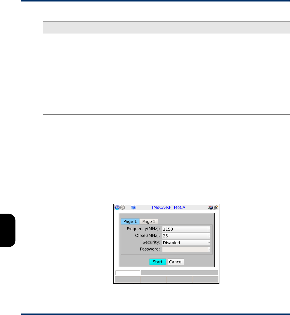
Tech-X Flex User Guide - Firmware v06.50 Tech-X Flex® (NG2)
7-6
Intro Overview Wi-Fi Ethernet System IP/Video MoCA RF Specs
Figure 7-2 Join MoCA network - Input parameters
Security
Password
Security information. If the network requires a password to join, enter that password
and set Security to Enabled. Otherwise, set Security to Disabled and disregard the
password.
Dependent upon licensing, the behavior of these fields may vary, such as:
• Some units may automatically disable security settings upon the selection of a
certain Frequency, under the assumption that target networks will not have related
security features enabled.
• Under Password, some units may provide the option of Auto, allowing the unit to
automatically attempt one or more preconfigured passwords. If your unit displays
this option, please contact a network administrator or Spirent for more information on
the password(s) that would be attempted.
Bridge (ECB)
mode
Enables or disables ECB bridge functionality. If you plan to do video testing, specify
Disabled. For more information, see About MoCA and 10/100/1G interface bridging
(ECB) on page 7-23.
NOTE: This feature will not function correctly if you have an active 10/100/1G
Admin Port established. For more information, see Admin Port on
page 5-5.
Preferred NC If set to Yes, causes the unit to attempt to assume the role of network coordinator (NC)
upon synchronization. Depending on network conditions and the behavior of other
nodes, the unit may not be successful or may lose the NC role at some point
afterwards.
Parameter Description
Preliminary issue - Limited distribution only!
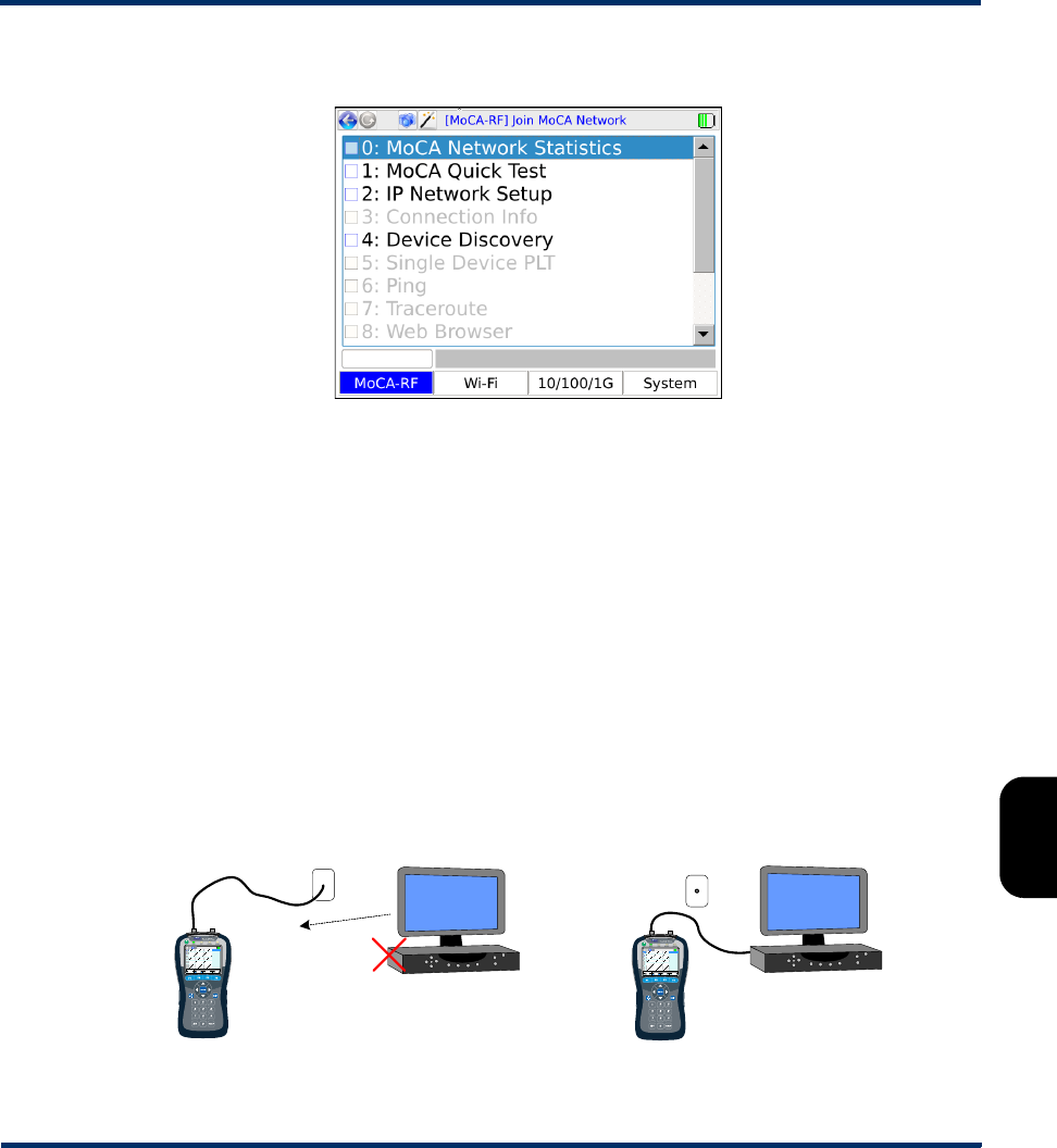
Tech-X Flex® (NG2) Tech-X Flex User Guide - Firmware v06.50
7-7
Intro
Overview
Wi-Fi
Ethernet
System
IP/Video
MoCA
RF
Specs
Once the unit has joined the MoCA network, the main statistics and testing menu becomes available:
Figure 7-3 Join MoCA network - Main menu
Single-ended testing setup for STB troubleshooting
When troubleshooting video issues, a common approach is to test at an STB location to rule out either
the STB or the associated coaxial cable as the cause. Common options for connection include:
•Replace the STB with the unit - In this scenario, the STB is disconnected and the unit is connected
to the main coaxial network for synchronization. This type of configuration can be useful for statistics
retrieval in an effort to isolate coaxial cable problems, as well as logical testing from the network
perspective of the STB.
•Connect directly to the STB - In this scenario, the unit and STB form a small, isolated MoCA
network between themselves which allows the same statistics retrieval as any MoCA
synchronization. If bandwidth between the devices is poor or synchronization cannot be achieved at
all, a likely cause is defective MoCA hardware in the STB.
Figure 7-4 Single-ended testing at an STB - Connection setups
TV/ STB
(disconnected)
Coax jack,
connecting to other
STBs, router, etc.
- or -
Preliminary issue - Limited distribution only!
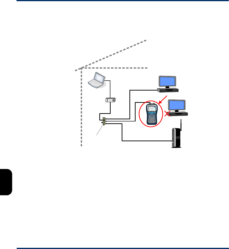
Tech-X Flex User Guide - Firmware v06.50 Tech-X Flex® (NG2)
7-8
Intro Overview Wi-Fi Ethernet System IP/Video MoCA RF Specs
NOTE: You must use the left port (port “A”) for all single-ended testing.
Using a generalization of the example shown in Figure 7-21 on page 7-33, the leftmost configuration
could effectively place the unit as follows:
Figure 7-5 Emulating an STB - Network diagram
Single-ended testing setup for router troubleshooting
When connecting at the router location, common options for connection include:
Coax/
MoCA
Coax splitter
MoCA STB
MoCA router
MoCA to
Ethernet
Cat 5 /
Ethernet
Preliminary issue - Limited distribution only!
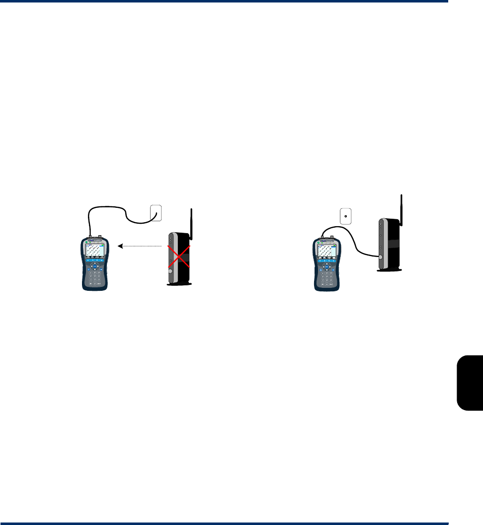
Tech-X Flex® (NG2) Tech-X Flex User Guide - Firmware v06.50
7-9
Intro
Overview
Wi-Fi
Ethernet
System
IP/Video
MoCA
RF
Specs
•Replace the router with the unit - In this scenario, the router is disconnected and the unit is
connected to the coaxial network for synchronization. If both the provider WAN and residential LAN
coexist on the same cable, this type of configuration may be useful for logical testing directly towards
the WAN, perhaps to rule out the router as the cause for connectivity issues. Otherwise, it may be
useful for general bandwidth-related troubleshooting. Note that if you disconnect the router, the LAN
will be isolated from the provider network, and, if the router provides a DHCP service, no IP-based
activity will be possible unless addresses are statically assigned.
•Connect directly to the router - In this scenario, the unit and router form a small, isolated MoCA
network between themselves which allows the same statistics retrieval as any MoCA
synchronization. If bandwidth between the devices is poor or synchronization cannot be achieved at
all, a likely cause is defective MoCA hardware in the router or possibly the cable used for the
connection.
Figure 7-6 Emulating a router - Possible connection setups
Note the following:
• You must use the left port (port “A”) for all single-ended testing.
• When connected directly to another MoCA node with a short cable, an attenuator may be necessary
if the signal is too strong (or “hot”) for proper synchronization. Implementations may vary... please
contact Spirent for recommendations.
7.3.2 MoCA Network Statistics
MoCA Network Statistics provides access to a variety of statistics about the network with which the unit
is synchronized, including packet counts, bandwidth, and bit-loading profiles. When initiated, the results
are presented on several different pages:
MoCA router
(disconnected)
Coax jack, connecting to
STBs, possibly the NT, etc.
- or -
Preliminary issue - Limited distribution only!
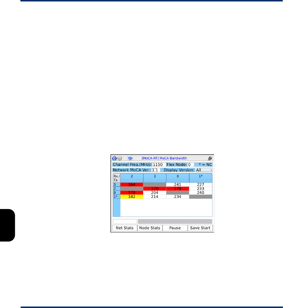
Tech-X Flex User Guide - Firmware v06.50 Tech-X Flex® (NG2)
7-10
Intro Overview Wi-Fi Ethernet System IP/Video MoCA RF Specs
•Bandwidth page (appears first) - Provides details on the available bandwidth between nodes on the
network (see Bandwidth page (MoCA Network Statistics) on page 7-10)
•MoCA Statistics page - Provides general information about the network, including details on
Ethernet traffic (see MoCA Statistics page (MoCA Network Statistics) on page 7-11)
•Node Stats page - Provides details on the links to every other node on the network, including bit-
loading profiles (see Node Stats page (MoCA Network Statistics) on page 7-13)
NOTE: When testing on a coaxial network that carries more than one MoCA network (such as a LAN
and a WAN), it is very important that you have synchronized with the correct network.
Otherwise, the statistics that you retrieve may be misleading. For example, WAN statistics will
not show the same nodes as the LAN, because certain nodes only belong to one or the other
despite the physical interconnectivity. For more information, see Example physical MoCA
network on page 7-32.
Bandwidth page (MoCA Network Statistics)
The Bandwidth page provides a table of the bandwidths between all nodes on the network, including the
unit. The table has a row and a column for each node in the network, with the “To” direction across the
top. For example, consider the following table:
Figure 7-7 Bandwidth page
This table shows that the bandwidth from node 3 to node 0 is 241 Mbps, while the bandwidth from node
0 to node 3 is 204 Mbps, and so forth. While reviewing a Bandwidth page table, note the following:
Preliminary issue - Limited distribution only!

Tech-X Flex® (NG2) Tech-X Flex User Guide - Firmware v06.50
7-11
Intro
Overview
Wi-Fi
Ethernet
System
IP/Video
MoCA
RF
Specs
• The unit arranges the table with the worst performing link shown at the top left, with improving
performance expanding towards the bottom right.
• The top of the screen indicates which node represents the unit (node 9 in this example). In the table
headings below, the network coordinator (NC) is indicated by an asterisk, which may or may not be
the unit.
• You can use the Display Version control to limit the table to nodes running a specific MoCA version.
• Any result shaded in red or yellow has violated a configured threshold (see Thresholds on
page 7-28).
• Gray (blank) table cells appear for the following reasons:
– When the cell would represent a link between a node and itself, which is not applicable.
– When the cell represents a link between two external nodes (neither of which are the unit) and the
network MoCA version is earlier than 1.1. Earlier versions of MoCA only support bandwidth
statistic retrieval for links involving the node from which they were queried (in this case, the unit).
– When the cell represents a link to or from a node that has been removed from the network, while
bandwidth reporting was in progress. If a node is removed, the unit does not remove the row and
column for that node; rather, it simply grays out any applicable cells.
• On the touchscreen, you can press any row or column header cell to jump to the node statistics page
for the respective node (see MoCA Statistics page (MoCA Network Statistics) on page 7-11).
• Real-world bandwidths will vary from the theoretical maximums allowed by the MoCA standards. A
lower bandwidth may indicate an issue with the physical network that is degrading performance, but
may not necessarily prove that the bandwidth reduction is causing any problems itself. As long as the
bandwidth is sufficient for the traffic that must traverse the respective link, a reduced bandwidth
should not exhibit any visible problems with the network.
Furthermore, the actual Ethernet bandwidth carried by a MoCA network is approximately 55% of the
MoCA-level bandwidth. Therefore, a MoCA network must maintain nearly 200 Mbps for a fully-
functional 100 Mbps Ethernet link.
• The bandwidth between two nodes is typically asymmetrical, with a different rate for each direction.
The difference is especially pronounced when the in/out polarity of splitters is reversed between
directions.
MoCA Statistics page (MoCA Network Statistics)
The MoCA Statistics page provides general details of the overall network. Note that unless otherwise
noted, results are cumulative since the time the unit joined the MoCA network. You can rest all counts to
zero by using the Reset command (F3).
Preliminary issue - Limited distribution only!
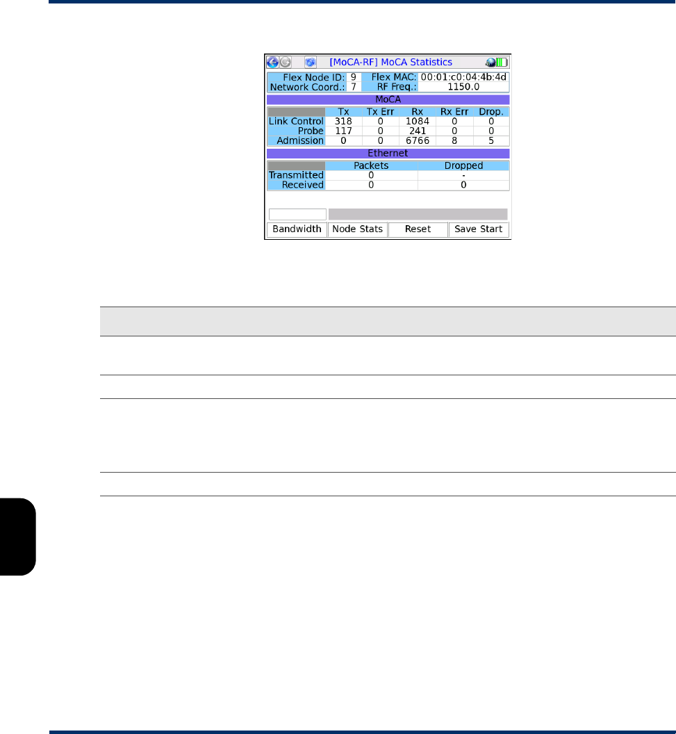
Tech-X Flex User Guide - Firmware v06.50 Tech-X Flex® (NG2)
7-12
Intro Overview Wi-Fi Ethernet System IP/Video MoCA RF Specs
Figure 7-8 MoCA Statistics page
Table 7-2 MoCA Statistics descriptions
Statistic Description
Flex Node ID The node ID assigned to the unit by the network coordinator (NC). All devices receive a
node ID from the NC upon admission.
Flex MAC MAC address of the physical MoCA interface on the unit.
Network
Coord
The node ID of the NC device (see Example physical MoCA network on page 7-32).
NOTE: On the Node Stats page, you can correlate a node ID with the MAC
address of the actual device (see Node Stats page (MoCA Network
Statistics) on page 7-13).
RF Freq Frequency of the MoCA channel in use (see MoCA physical layer on page 7-36).
Preliminary issue - Limited distribution only!

Tech-X Flex® (NG2) Tech-X Flex User Guide - Firmware v06.50
7-13
Intro
Overview
Wi-Fi
Ethernet
System
IP/Video
MoCA
RF
Specs
Node Stats page (MoCA Network Statistics)
The Node Stats page provides an independent set of statistics for each node in the network, including
the unit itself. Each node has its own tab, on which the Tx column represents the link from the unit to the
respective node and the Rx column represents the link to the unit from the respective node. The first tab
always represents the unit itself, with other tabs representing other nodes on the network. Note the
following:
Link Control
Probe
Admission
Details on the count of frames received by and transmitted from the unit, according to
frame type:
•Tx - Frames transmitted from the unit, to any other node.
•Tx Err - Frames transmitted that did not reach the destination and/or contained
errors that could not be corrected by Reed-Solomon algorithms. These errors may
indicate a problem with the physical cable that caused frame corruption or possibly a
problem with the destination node(s).
•Rx - Frames received by the unit, from any other node.
•Rx Err - Frames received that contained uncorrectable errors. These errors
normally indicate frame corruption that occurred during the transit over the coaxial
cable.
•Drop - Received frames that could not be processed due to insufficient buffer space
(that is, too much traffic for the unit to handle) and/or frames that were expected to
be received based on NC scheduling, but never arrived.
Note the following:
• For more information on how Link Control, Probe, and Admission frames operate
on the network, see MoCA functional overview on page 7-35.
• The mechanisms by which a MoCA network manages traffic as related to these
frame counts is complex and beyond the scope of this document. See the respective
MoCA specification for more details.
Ethernet
statistics
Statistics on the Ethernet frames received and transmitted by the unit carrying user
data, such as IP video packets, as follows:
•Packets - Number of frames sent to and received from any other node on the
network
•Dropped - Frames dropped due to insufficient buffer space
These measurements are taken at the Ethernet switch “behind” the MoCA interface, as
frames transit from MoCA to standard Ethernet for internal processing. Note that these
statistics are stored in 16-bit registers and therefore may roll over periodically.
Statistic Description
Preliminary issue - Limited distribution only!
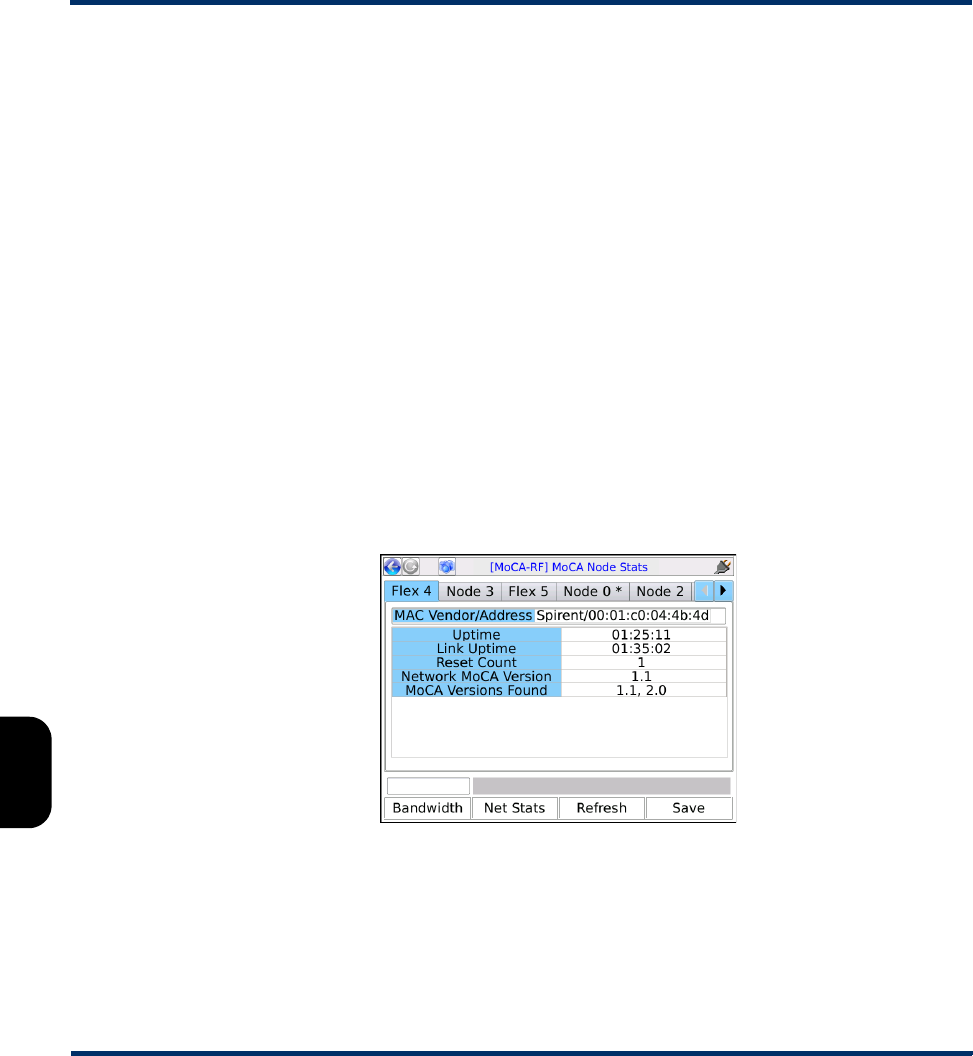
Tech-X Flex User Guide - Firmware v06.50 Tech-X Flex® (NG2)
7-14
Intro Overview Wi-Fi Ethernet System IP/Video MoCA RF Specs
• Another Tech-X Flex unit elsewhere on the network would appear as any other remote node for the
purpose of these screens, except that the tab in the Node Stats page will include the prefix “FLEX”.
• You can set these values to appear in red if specified thresholds are exceeded. For more information,
see Thresholds on page 7-28.
• Some of these results involve complex characteristics of a MoCA network which are beyond the
scope of this document to describe. See the respective MoCA specification for more details.
The first tab (for the unit itself) includes the following information:
•MAC Vendor/Address - The vendor (Spirent) and MAC address of the unit MoCA interface.
•Uptime - Amount of time since the initialization of the module. The module is initialized when a
MoCA-specific function is launched, such as Join MoCA Network, not necessarily the same time
that the MoCA menu is first accessed.
•Link Uptime - Amount of time that the module has been synchronized on a the current network.
•Reset Count - Number of times that the module has been resynchronized.
•Network MoCA Version - The lowest version of the MoCA standard running on the network to which
the unit is synchronized. For example, if a v1.1 node is present on the network, this field will report
1.1, even if the network includes other nodes using v2.0. For more information on multiple MoCA
versions on a single network, see About multiple MoCA versions on a single network on page 7-38.
•MoCA Versions Found - A list of all MoCA versions detected in use on the network.
Figure 7-9 Node Stats page (Unit tab)
All other tabs (for other network nodes) include the following information:
Preliminary issue - Limited distribution only!

Tech-X Flex® (NG2) Tech-X Flex User Guide - Firmware v06.50
7-15
Intro
Overview
Wi-Fi
Ethernet
System
IP/Video
MoCA
RF
Specs
Table 7-3 Node Stats
Statistic Description
Vendor/
MAC
MAC-layer address of the node’s MoCA interface and the vendor name associated with
it. The unit attempts to determine the vendor by using a MAC address lookup table in the
System menu area. If the vendor cannot be determined, it is reported as Unknown. For
more information, see Vendor MAC Address on page 7-27.
Node
Version
Highest level of MoCA supported by the node, but not necessarily the version in use by
the node. For more information, see About multiple MoCA versions on a single network
on page 7-38.
State State of the node, typically one of:
•MAP Active - The node is actively participating on the network in a normal manner.
•Idle - The node is recognized as a valid node but has entered a state of inactivity,
such as a “sleep” mode. All bandwidth to and from the node will be reported as zero.
Bit Rate The physical layer bit rates to and from the node (Tx and Rx) in Mbps, up to the
theoretical MoCA maximum of the respective standard (see MoCA overview on
page 7-31).
CP-LEN
(Cyclic Prefix
Length)
The size of the guard interval applied to MoCA symbols in each direction to protect the
symbols from interference. Larger lengths reduce bit rates and thus reduce the
bandwidth.
Phase
Offset
The phase difference between the MoCA channel’s reference center frequency and the
actual center frequency, in Hz. When phase offset increases, it diminishes the ability of a
MoCA receiver to properly demodulate the channel subcarriers. Large values, such as
47000 or higher, lower the margin for interoperability.
Log Gain
Mean
The average amount of gain required to amplify the MoCA carriers received by the unit.
A higher gain value corresponds with greater attenuation between the unit and the node
under test. The valid range is 0-68 dB. Because this parameter applies to the behavior of
the receiver, it always displays as N/A for the transmit direction.
Power
Adjust
The amount that the unit’s transmit power is reduced from reference power. A lower
value indicates that more power is required and therefore corresponds with greater
attenuation between the unit and the node under test. A larger number indicates more
power reduction, therefore the larger the number, the “cooler” the signal and vice-versa.
The range is 0-30 dB in multiples of 3 dB. Because this parameter applies to the
behavior of the transmitter, it always displays as N/A for the receive direction.
Preliminary issue - Limited distribution only!
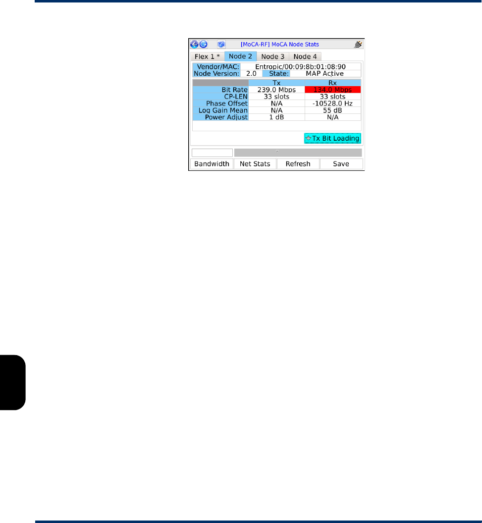
Tech-X Flex User Guide - Firmware v06.50 Tech-X Flex® (NG2)
7-16
Intro Overview Wi-Fi Ethernet System IP/Video MoCA RF Specs
Figure 7-10 Node Stats page (Any node except the unit)
The Node Stats page also includes links to bit-loading graphs which chart the number of bits that
subcarrier frequencies are carrying (per symbol), across the MoCA channel in use. An active network
continuously adjusts the number bits each symbol is expected to carry (that is, adjusts the QAM level),
loading each subcarrier to the maximum amount that probe exchanges have determined is feasible for
reliable transmission. Therefore, a bit-loading graph is essentially a granular view of channel bandwidth.
If the coaxial cable has impairments which cause excessive attenuation, a bit-loading graph should show
large trends of lower bit loading across the channel, causing a degradation of overall bandwidth.
Each tab has two bit-loading graphs, one for transmitting from the unit to the respective node (Tx) and
one for transmitting from that node to the unit (Rx). For the tab representing the unit itself, the graphs
should be blank because transmission to itself is not applicable.
A bit-loading graph presents all available subcarriers on the x-axis and plots the number of bits that each
is carrying on the y-axis (8 bits maximum for 128-QAM, 10 bits for 1024-QAM, see MoCA physical layer
on page 7-36). As a MoCA 1.1 example, the following graph shows an Rx link from Node 7 that is
performing well. All subcarriers are carrying 6 or more bits per symbol:
Preliminary issue - Limited distribution only!
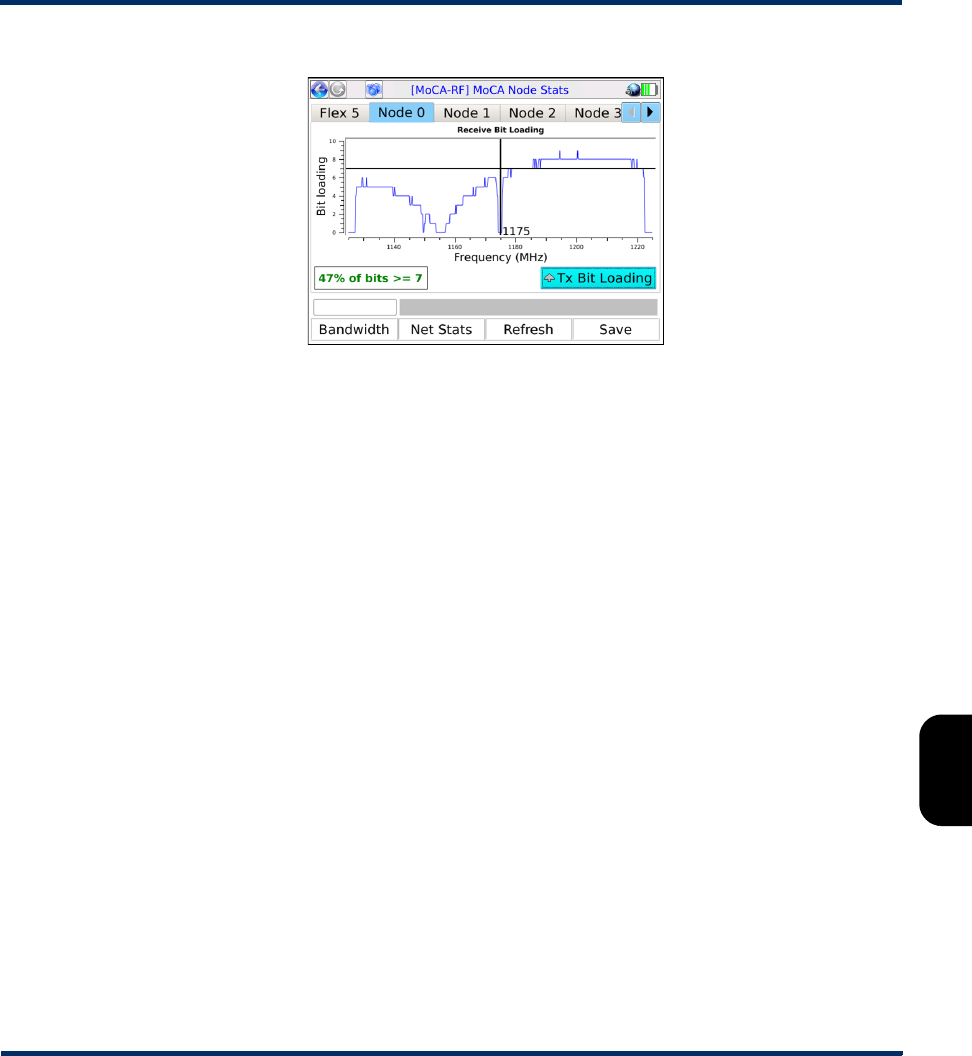
Tech-X Flex® (NG2) Tech-X Flex User Guide - Firmware v06.50
7-17
Intro
Overview
Wi-Fi
Ethernet
System
IP/Video
MoCA
RF
Specs
Figure 7-11 Bit-loading graph
Note the following about bit-loading graphs:
• The graphs indicate the center frequency of the MoCA channel with a red line. The bit-loading “notch”
at this frequency is normal.
• A bit-loading graph is not intended to provide information for precise troubleshooting of the MoCA
physical layer. Rather, it intends to provide an overall view of trends in data capacity over the MoCA
channel to help identify bandwidth issues between the applicable nodes.
7.3.3 IP Network Setup
IP Network Setup allows you to assign IP information to the active MoCA interface, which provides
access to IP-based functions including video testing. The setup operates identically to IP Network Setup
on other interfaces, such as the Wi-Fi and 10/100/1G interfaces. For more information, see IP Network
Setup on page 6-1.
Note that DHCP-based address assignment will only work if the unit is synchronized with a network that
has an active DHCP server. In the case where the unit is in-line on a LAN network, a DCHP server is
likely to be available on one side only (that is, the router side). If the unit is connected directly to an STB
or similar device in a single-ended configuration, no DCHP server is likely to be available.
7.3.4 IP Testing options over MoCA
The MoCA interface provides a suite of IP testing functions that are generally identical to their
counterparts launched from other interfaces. The following table provides links to the central locations in
this document that describe these tests in detail, along with any additional notes that may be relevant to
the MoCA interface.
Preliminary issue - Limited distribution only!

Tech-X Flex User Guide - Firmware v06.50 Tech-X Flex® (NG2)
7-18
Intro Overview Wi-Fi Ethernet System IP/Video MoCA RF Specs
Table 7-4 IP testing options from the MoCA interface
7.3.5 IP Video Tests
Once the MoCA interface is configured with valid IP information, the following IP video tests are
available, assuming the availability or presence of an IP video stream:
Test For more information Additional notes
Connection Info Results - IP Network Setup on
page 6-3
This function reports the IP information that is
currently assigned to the 10/100/1G interface
and is identical to the results screen from any
successful IP Network Setup.
Device Discovery All Devices Packet Loss
(Device Discovery) on
page 6-19
The Device Discovery test is the same test
as All Devices Packet Loss, named
differently because its likely purpose is to
discover devices on the current subnet, which
is the initial phase of the All Devices Packet
Loss test. If desired, you can continue with
the packet loss portion of the testing or cancel
the test after the discovery phase.
IP Video Tests IP Video testing on page 6-22 - - -
L4 Performance Test L4 Performance Test on
page 6-7
- - -
Packet Capture Packet Capture on page 6-55 - - -
Ping Ping on page 6-4 - - -
Single Device PLT Single Device PLT on
page 6-11
- - -
Speed Test Speedtest on page 6-17 - - -
Traceroute Traceroute on page 6-6 - - -
Video QoS Video QoS (Quality of Service)
on page 6-23
- - -
Web Browser Web Browser on page 6-10 - - -
Preliminary issue - Limited distribution only!
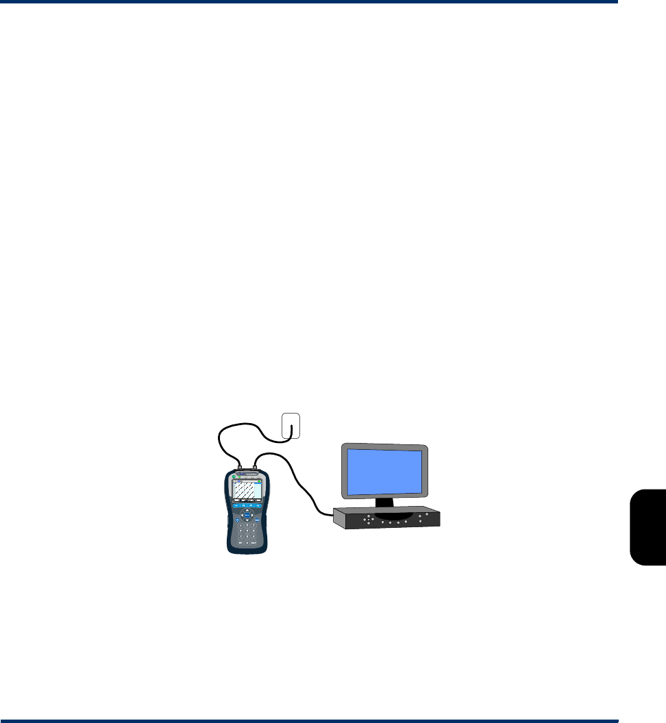
Tech-X Flex® (NG2) Tech-X Flex User Guide - Firmware v06.50
7-19
Intro
Overview
Wi-Fi
Ethernet
System
IP/Video
MoCA
RF
Specs
•Video QoS (Quality of Service) - Actively joins a multicast stream and measures the subjective
video quality. This test operates identically to the Video QoS test on other interfaces, such as the
10/100/1G interface. For more information, see Video QoS (Quality of Service) on page 6-23.
•Change Channel - Actively joins a multicast stream and measures the time required to switch to
another stream (that is, to “change the channel”). This test operates identically to the Channel
Change test on other interfaces, such as the 10/100/1G interface. For more information, see Change
Channel on page 6-51.
•Channel Guide Settings - Allows you to configure the use of a channel guide for IP video testing,
identical to other comparable functions on the unit. For more information, see Channel Guide
Settings on page 6-53.
7.4 Join MoCA Network In-Line (Bridging and passive testing)
(Select MoCA-RF > MoCA > Join MoCA Network In-line)
The MoCA module features dual MoCA interfaces which allow the unit to bridge traffic on a MoCA
network and perform passive monitoring, typically for video quality measurement. For example, the unit
could be placed in-line with an STB to monitor video traffic flowing across the bridge to the STB:
Figure 7-12 Bridged MoCA connection setup - Example
Once a bridge is established, the unit can also perform the full suite of active testing in either direction.
MoCA STB
(connected)
Coax jack,
connecting to other
STBs, router, etc.
Preliminary issue - Limited distribution only!
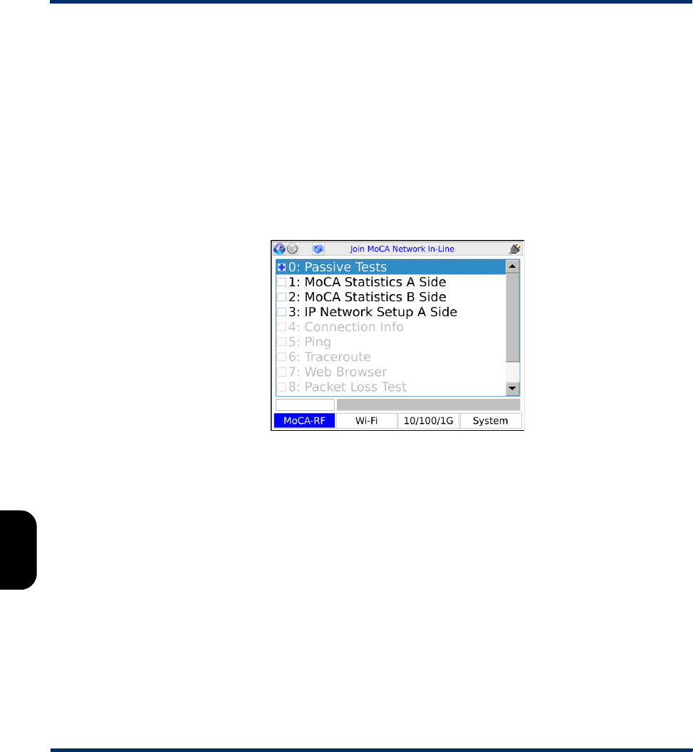
Tech-X Flex User Guide - Firmware v06.50 Tech-X Flex® (NG2)
7-20
Intro Overview Wi-Fi Ethernet System IP/Video MoCA RF Specs
7.4.1 Join MoCA Network In-Line setup parameters
The setup parameters are functionally identical to those in the Join MoCA Network setup screen. For
more information, see Join MoCA network setup parameters on page 7-5.
Additionally, note the following:
• Be sure that the unit is properly connected on the network before attempting the join. For more
information, see Where to place the unit for bridging on page 7-21.
• The specified parameters (Frequency, etc.) are used for each side, under the assumption that you
are bridging two segments of the same network.
• Upon successful synchronization, the main in-line testing menu appears:
Figure 7-13 Main in-line testing menu
• ECB functionality (if enabled) is only available for the “B” side network. For more information, see
About MoCA and 10/100/1G interface bridging (ECB) on page 7-23
• The in-line testing menu provides IP-related functionality for the A side of the connection, which
operates identically to a single-ended connection established with the Join MoCA network
command. See the respective areas of this document for more information, such as IP Network
Setup on page 7-17.
NOTE: The process of obtaining an IP address may temporarily disrupt video-on-demand (VOD)
traffic. If you have a video stream running, you may need to restart it after address retrieval.
• If passive testing is desired afterward, you may need to re-initiate the desired stream (such as a video
stream), because the stream may not be present after the interruption caused by disconnecting the
cable. For example, if you want to perform passive video testing, use the STB to select a channel to
start the stream.
Preliminary issue - Limited distribution only!
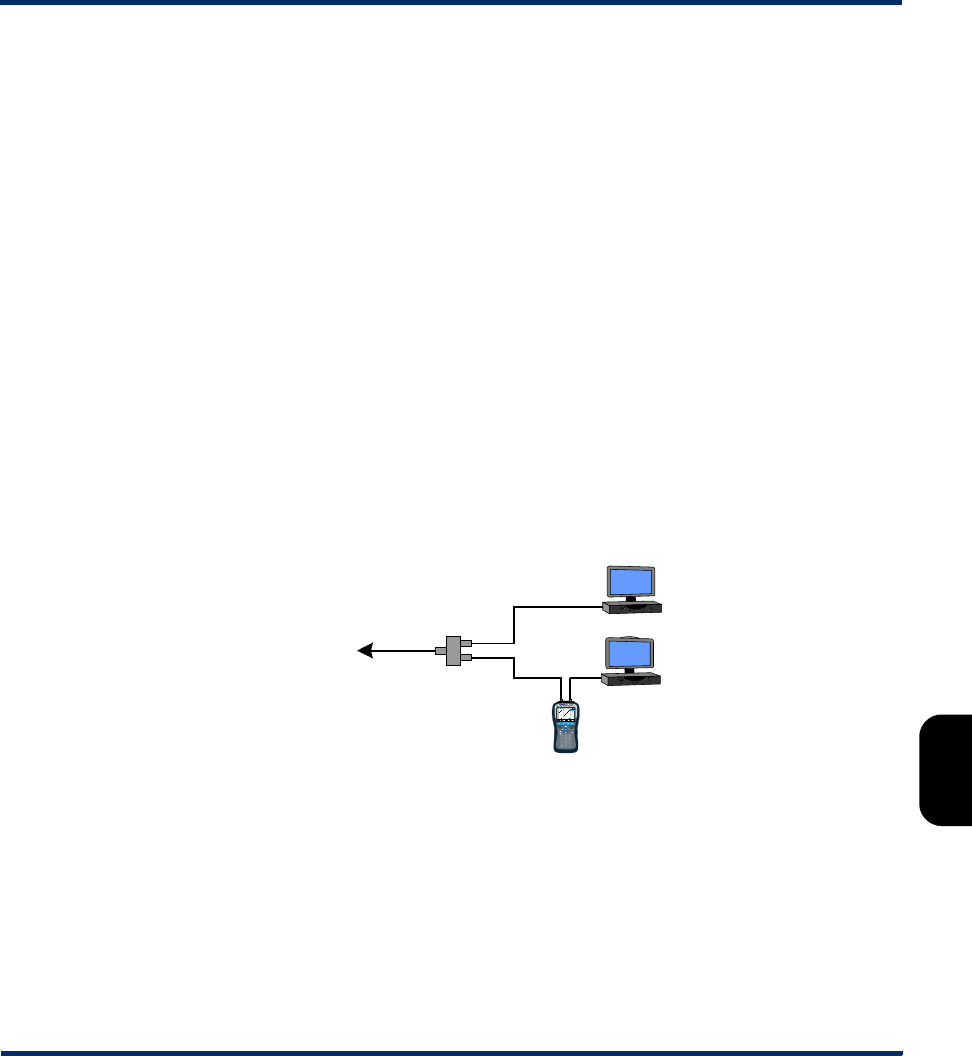
Tech-X Flex® (NG2) Tech-X Flex User Guide - Firmware v06.50
7-21
Intro
Overview
Wi-Fi
Ethernet
System
IP/Video
MoCA
RF
Specs
NOTE: If you have set up the bridge properly, you should be able to view the video channel on a
TV, even while testing the stream for quality. Therefore, a TV may be the best way of ensuring that
the test stream has been started.
7.4.2 Bridge setup and operational details
The following sections describe the bridging process and setup in more detail:
•Where to place the unit for bridging on page 7-21
•Bridging a cable with multiple networks on page 7-22
Where to place the unit for bridging
The primary reason for creating the bridge is to passively monitor traffic. Therefore, you must place the
unit between the router and the device receiving the traffic, such as an STB. For example, the following
setup would allow you to monitor video traffic received by STB 2:
NOTE: Always connect the “A” side port in the direction of the router.
Figure 7-14 Bridging example - Correct
Note that this setup provides visibility to STB 2 traffic only. To monitor STB 1 traffic, the unit would need
to be placed between the router and that STB.
When setting up the bridge, you should be sure that there is no external connectivity between the two
MoCA ports. The unit attempts to join separate MoCA networks with the same channel on each side,
which is not possible if the cable is interconnected. For example:
Splitter
To router
RIGHT STB 1
STB 2
Preliminary issue - Limited distribution only!
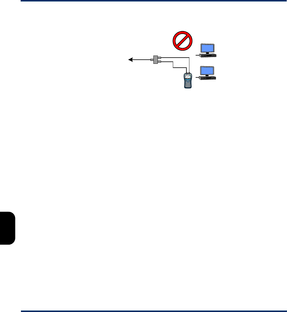
Tech-X Flex User Guide - Firmware v06.50 Tech-X Flex® (NG2)
7-22
Intro Overview Wi-Fi Ethernet System IP/Video MoCA RF Specs
Figure 7-15 Bridging example - Incorrect
NOTE: In the case where a WAN and LAN both operate on the same cable, the unit can bridge a single
channel only. See Bridging a cable with multiple networks on page 7-22 for important details on
this and other operational details.
Bridging a cable with multiple networks
The unit bridges a single MoCA channel only. Therefore, for architectures where a LAN and WAN both
operate on the same cable, one network will be effectively blocked while the unit is synchronized with the
other, at the point where the unit is connected. In most circumstances, this will have no adverse effect on
the network or related testing, as most devices belong to a single network only. If the unit is configured as
recommended in this documentation, no disruption of overall LAN/WAN functionality should occur.
7.4.3 Passive video testing
From the main in-line testing menu (Figure 7-13 on page 7-20) you can select Passive Tests > Unicast
Video QoS or Passive Tests > Multicast Video QoS to launch a passive video quality measurement
test. From the standpoint of input parameters and test results, these tests are identical to their active,
single-ended counterparts except that the unit does not join a video stream. Rather, it uses the specified
IP address and other identifying information to mirror an existing stream to the analysis software, leaving
the original stream unaffected. For more information on general setup for passive video testing, see
Bridge setup and operational details on page 7-21.
7.4.4 In-line MoCA statistics
When you select MoCA Statistics A Side or MoCA Statistics B Side from the main in-line menu, the
unit proceeds to statistics pages for the network on the respective side. All of the functions in these
Splitter
To router
WRONG
Preliminary issue - Limited distribution only!
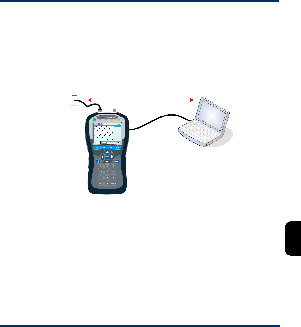
Tech-X Flex® (NG2) Tech-X Flex User Guide - Firmware v06.50
7-23
Intro
Overview
Wi-Fi
Ethernet
System
IP/Video
MoCA
RF
Specs
pages are identical to their single-ended testing counterparts, except that you previously chose which
side (A or B) to test. For more information, see MoCA Network Statistics on page 7-9.
7.4.5 About MoCA and 10/100/1G interface bridging (ECB)
Because the MoCA and 10/100/1G interfaces are logically connected by a common Ethernet switch, the
unit can act as a bridge between MoCA and Cat-5 Ethernet, commonly called an ECB (Ethernet/coax
bridge). For example, the unit can allow a computer to join the MoCA-based LAN or WAN through its
10/100/1G interface:
Figure 7-16 Bridging a computer to the network
ECB functionality must be specifically enabled when you join a MoCA network. Currently, the unit does
not provide any test functions directly related to this bridge setup, but the use of a laptop on the network
may be useful for isolating problems with Ethernet bridging devices and perhaps advanced functions
using the computer itself.
7.5 MoCA Quick Test
(Select MoCA-RF > MoCA > MoCA Quick Test)
-or-
(MoCA-RF > MoCA > Join MoCA Network > MoCA Quick Test)
Coax
10/100/1G
interface
Ethernet
IP traffic
Preliminary issue - Limited distribution only!

Tech-X Flex User Guide - Firmware v06.50 Tech-X Flex® (NG2)
7-24
Intro Overview Wi-Fi Ethernet System IP/Video MoCA RF Specs
The MoCA Quick Test is a set of existing MoCA activities, organized into a single, scripted test for a
quick and comprehensive analysis of a MoCA network.
7.5.1 Testing flow and results (MoCA Quick Test)
The test can be run before or after the unit has joined a MoCA network. If run before, the first step is to
join the network using the parameters specified in the setup screen; otherwise, that step is skipped. Once
the unit is fully synchronized, the remainder of the MoCA Quick Test involves the retrieval and
evaluation of a variety of network statistics. These statistics represent the same data that can be
retrieved manually (see MoCA Network Statistics on page 7-9), except that the MoCA Quick Test
automatically evaluates all applicable thresholds to present a simple pass/fail summary of network
conditions.
NOTE: The unit can apply delays during the initiation of the test that may be essential for producing
meaningful results. For more information, see About intentional test delays (MoCA Quick Test)
on page 7-26.
While the test runs, it produces a running status of events in a Log tab. The following list describes the
general stages of the test and the meaning of the results.
1. Determination of network type and existing nodes - The test reports the MoCA version in use and
a summary of all nodes active on the network, including the unit. All subsequent stages also include
the unit as applicable.
2. Bandwidth evaluation - The test analyzes the bit rates of all paths between all nodes, looking for
any threshold violations. The data analyzed is the same as described under Bandwidth page (MoCA
Network Statistics) on page 7-10.
3. MoCA network statistics evaluation - The test analyzes general MoCA statistics, such as packet
loss and error counts. A single lost or errored packet will fail this stage. The data analyzed is the
same as described under MoCA Statistics page (MoCA Network Statistics) on page 7-11.
4. Ethernet statistics evaluation - The test analyzes general Ethernet statistics, such as packet loss
and error counts. A single lost or errored packet will fail this stage. The data analyzed is the same as
described under MoCA Statistics page (MoCA Network Statistics) on page 7-11.
5. Node stats evaluation - The test analyzes statistics separately for each network node (that is, the
path between the unit and each node), the same data described under Node Stats page (MoCA
Network Statistics) on page 7-13.
6. Bit loading evaluation - Related to the general node stats, the test analyzes the bit loading for the
receive and transmit links for each node, the same bit loading data as described under Node Stats
page (MoCA Network Statistics) on page 7-13.
7. Summary - When the test finishes, it presents a general summary, including an overall evaluation of
the network labeled MoCA network. If any stage has produced a failed result, the entire test receives
Preliminary issue - Limited distribution only!
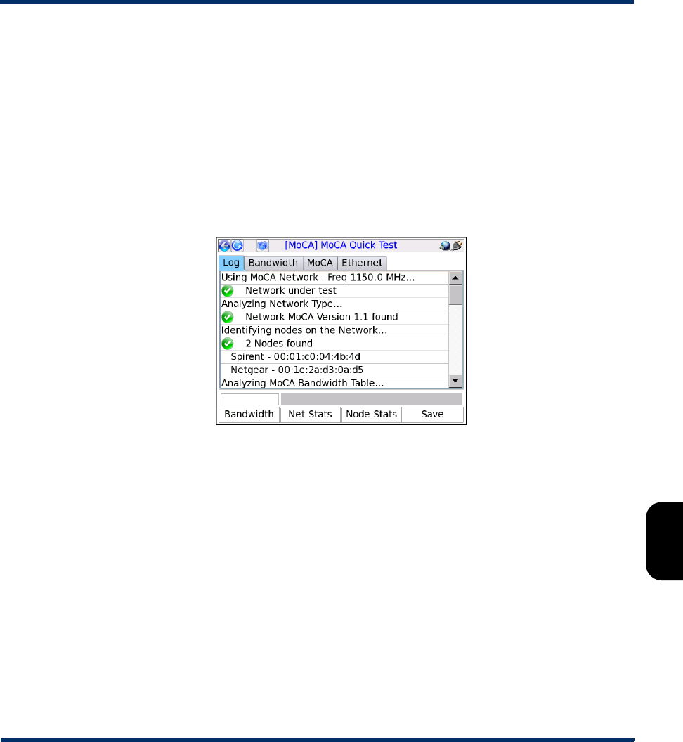
Tech-X Flex® (NG2) Tech-X Flex User Guide - Firmware v06.50
7-25
Intro
Overview
Wi-Fi
Ethernet
System
IP/Video
MoCA
RF
Specs
an evaluation of FAIL. If any stage has produced a marginal result but no stages failed, the network
receives an evaluation of MARGINAL.
In the Log tab, stages are marked using colored icons according to thresholds that were evaluated
during the process. A single failed evaluation causes the respective stage to be marked as such. In the
absence of any failures, a single marginal evaluation causes the respective stage to be marked as such.
Note that a failure does not mean that the testing process could not complete, only that a threshold was
violated. For more information on thresholds and coloring, see View/Edit Thresholds on page 7-28.
NOTE: If a stage is marked as marginal or failing, you can press the respective area on the
touchscreen in the Log tab to jump to those respective results.
Figure 7-17 MoCA Quick Test results - Log tab
In addition to a log of these stages, the test also produces a set of tabs that show much of the actual data
that was measured and analyzed. These tabs have some similarity to the pages produced when
manually retrieving network statistics, except that the MoCA Quick Test displays non-updating
snapshots of the data retrieved during the test only. For any node that produced a metric violation, a
separate tab is also produced showing the applicable details on that specific node:
Preliminary issue - Limited distribution only!
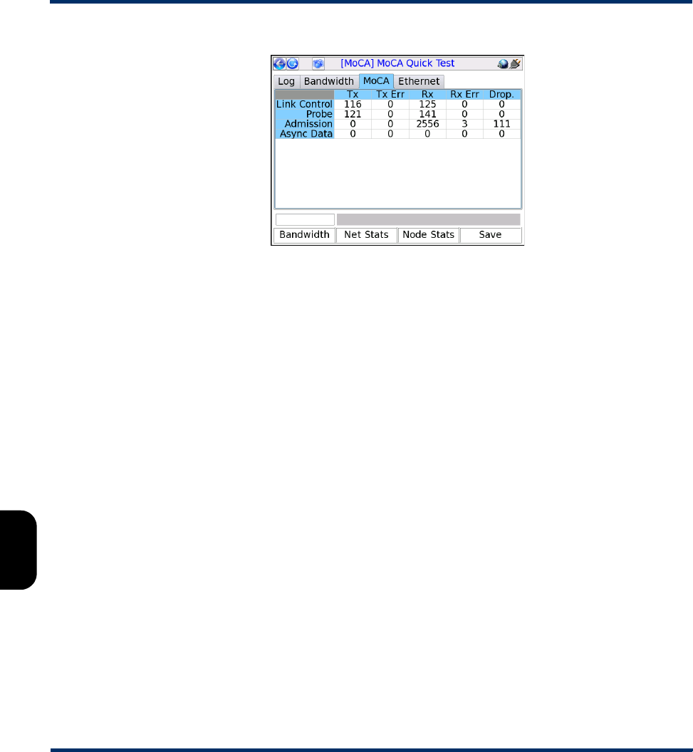
Tech-X Flex User Guide - Firmware v06.50 Tech-X Flex® (NG2)
7-26
Intro Overview Wi-Fi Ethernet System IP/Video MoCA RF Specs
Figure 7-18 MoCA Quick Test results - MoCA tab
7.5.2 About intentional test delays (MoCA Quick Test)
Optionally, you can introduce delays into the MoCA Quick Test process to reduce the possibility that
non-applicable errors will cause the test to fail. These delays are configured in the MoCA thresholds area
(see Thresholds on page 7-28). The following paragraphs explain the purpose of these delays in more
detail.
When a device (such as the unit) joins a MoCA network, some instability is expected as that device
negotiates and forms the link. This instability may include reduced bandwidth and/or dropped packets
such as MoCA admission packets. Therefore, to account for initial network instability and to prevent
spurious failures of the MoCA Quick Test due to normal network behavior, the test provides two
configurable delays:
•“Initialize” delay - A delay between the initial network synchronization and the time when the unit
begins to monitor network traffic. After the expiration of this period, all previous data is discarded and
packet count registers and other results are reset as applicable.
NOTE: In the Thresholds area, you can select a value of Auto for this setting. With this setting,
the unit automatically selects a delay based on the total number of nodes detected on the network
at the time of synchronization, with a higher number producing a longer delay. For example, 8
nodes will cause approximately 1 minute of delay, while 16 nodes will cause approximately 3
minutes. For optimal performance (especially on networks with fewer nodes), Auto is
recommended.
•“Settle” delay - A delay between the expiration of the “initialize delay” and the time that the primary
portions of the analysis begin.
Preliminary issue - Limited distribution only!

Preliminary issue - Limited distribution only!

Tech-X Flex® (NG2) Tech-X Flex User Guide - Firmware v06.50
7-27
Intro
Overview
Wi-Fi
Ethernet
System
IP/Video
MoCA
RF
Specs
In summary, the two delays work together to allow the network to stabilize, then to allow enough traffic to
arrive in order to produce meaningful results. Note that when the MoCA Quick Test is launched while
the unit is currently synchronized to a network, the “initialize” delay is never used; however, packet count
and result registers are always reset before proceeding with any MoCA Quick Test analysis. If a “settle”
delay is configured, it is always implemented regardless of whether the unit was synchronized initially.
The unit is preconfigured with defaults for these settings. If you do not know the precise settings that are
applicable to your testing architecture, Spirent recommends that you maintain the defaults.
7.6 System menu settings/controls (for MoCA)
Under System > System/Module Settings > MoCA-RF Module > MoCA, the following areas are
available that control important module settings:
•Vendor MAC Address on page 7-27
•Thresholds on page 7-28
7.6.1 Vendor MAC Address
(Select System > System/Module Settings > MoCA-RF Module > MoCA > Vendor MAC Address)
The Vendor MAC lookup table associates MAC addresses with equipment manufacturers/vendors, used
to correlate an address with its respective vendor in the Node Stats screens (see Node Stats page
(MoCA Network Statistics) on page 7-13.) That is, the unit is able to determine MAC addresses from the
network, but it may need to use this table to correlate an address with a vendor name. During testing, if
the unit is unable to correlate an address with a vendor in this table, it reports the vendor as Unknown.
Typically, the IEEE issues MAC addresses to a specific vendor in blocks which can be identified by the
first 6 octets (first 6 hexadecimal digits). As such, the lookup table should contain any 6-digit prefixes that
the unit might encounter, along with the vendors to which they apply. From the factory, the table is
prepopulated with a set of known values for current MoCA equipment vendors. If necessary, the screen
allows you to edit and augment the table. Note that the Description is for informational purposes only
within the lookup table.
Preliminary issue - Limited distribution only!
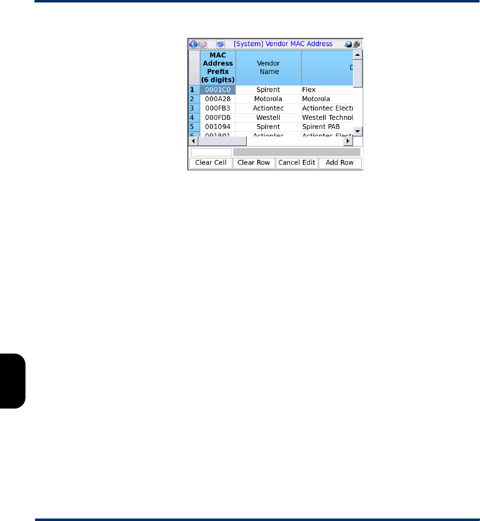
Tech-X Flex User Guide - Firmware v06.50 Tech-X Flex® (NG2)
7-28
Intro Overview Wi-Fi Ethernet System IP/Video MoCA RF Specs
Figure 7-19 Vendor MAC Address lookup table
NOTE: The unit has an additional, internal table that it uses to look up any address not contained in the
Vendor MAC Address table. This internal table contains information similar to any publicly-
available address lookup on the internet. If the unit correlates an address using the internal
table, it may add the corresponding entry to the Vendor MAC Address table. In this manner,
you have the opportunity to edit the vendor information that appears subsequently for that
address range.
7.6.2 Thresholds
(Select System > System/Module Settings > MoCA-RF Module > MoCA > Thresholds)
This screen provides access to:
•View/Edit Thresholds on page 7-28 - Allows you to view and possibly edit individual thresholds on the
unit
•Download Thresholds on page 7-30 - Allows you to set all thresholds as a batch by importing a
threshold settings file
View/Edit Thresholds
(Select System > System/Module Settings > MoCA-RF Module > MoCA > Thresholds > View/Edit
Thresholds)
The threshold table allows you to view and edit values that affect:
Preliminary issue - Limited distribution only!

Tech-X Flex® (NG2) Tech-X Flex User Guide - Firmware v06.50
7-29
Intro
Overview
Wi-Fi
Ethernet
System
IP/Video
MoCA
RF
Specs
• The coloring of results in the network statistics pages (see MoCA Network Statistics on page 7-9)
• Pass/marginal/fail determinations during the MoCA Quick Test (see MoCA Quick Test on page 7-23)
• Certain other behaviors of the MoCA Quick Test
Thresholds are specified as ranges, such as “Pass” ranges and “Fail” ranges. For coloring and
evaluations related to thresholds, the unit uses:
•Red/Fail for a metric that falls within the “Fail” range
-or-
If the respective threshold does not include a “Fail” range, a metric that falls outside the “Pass” range
•Yellow/Marginal for a metric that falls within a “Marginal” range, if the respective threshold includes
such a range
•Green/Pass (or no coloring) for a metric that falls within the “Pass” range
Additionally, note the following:
• When specifying thresholds, the unit enforces theoretical/technical limitations. For example, a bit rate
cannot be less than zero. In general, if the inherent lower or upper range of a threshold represents a
technical limit, the unit restricts the editing of the field altogether.
• For thresholds with pass, marginal, and fail ranges, the unit enforces continuity between the ranges,
normally by disallowing the editing of certain fields. For example, the marginal Bit Rate range is
automatically determined by the lower Pass and upper Fail values and is therefore restricted from
editing.
• In the Enabled column, you can disable any specific threshold which causes the threshold to have no
effect on coloring or pass/fail evaluations. This feature may be useful for situations where testing with
the unit is required but a final determination of appropriate pass/fail criteria has not yet been made.
The following table describes the supported thresholds.
Bit Rate
CP Len
Phase Offset
Log Gain Mean
Power Adjust
Determine the valid range for the respective parameters in the Node Stats
pages and for the corresponding stages during a MoCA Quick Test (see
Node Stats page (MoCA Network Statistics) on page 7-13). Additionally, the
Bit Rate ranges determine the valid ranges for the bit rates between any
two devices during the retrieval of the bandwidth table (see Bandwidth
page (MoCA Network Statistics) on page 7-10).
Bit Loading (%)
Bit Loading (bits)
Together, determine when a bit loading profile is sufficiently robust, used for
pass/fail evaluations during the MoCA Quick Test. If at least the specified
percentage of subcarriers are carrying at least specified number of bits, the
bit loading is considered passing. Otherwise, it is considered a failure.
For general information on bit loading, see Node Stats page (MoCA
Network Statistics) on page 7-13.
Preliminary issue - Limited distribution only!
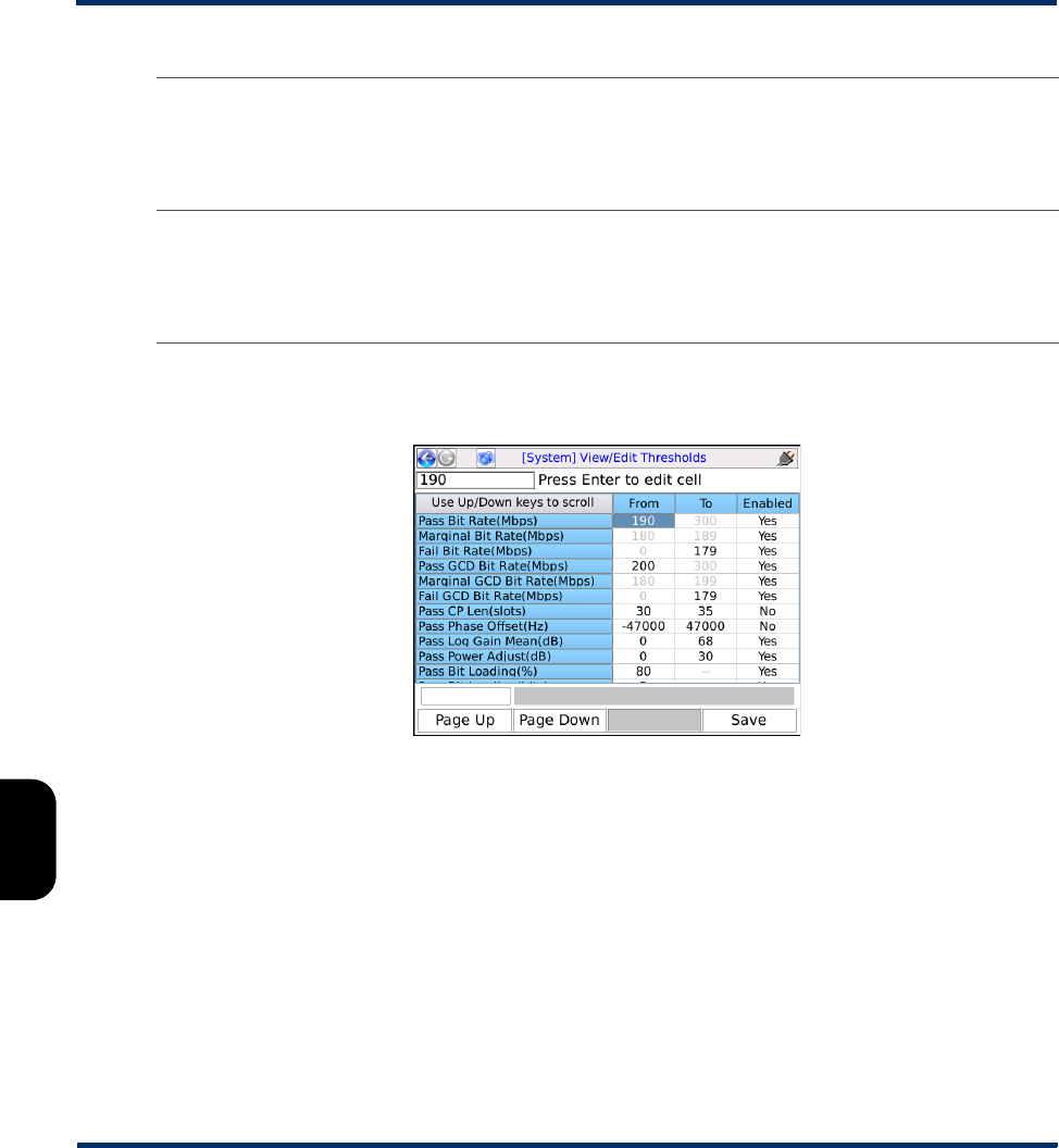
Tech-X Flex User Guide - Firmware v06.50 Tech-X Flex® (NG2)
7-30
Intro Overview Wi-Fi Ethernet System IP/Video MoCA RF Specs
As an example, with the following setup, a Bit Rate value in the Node Stats screen would be colored
yellow if it were between 180 and 189 Mbps and red if it were any higher:
Figure 7-20 Thresholds screen
Download Thresholds
As an alternative to editing thresholds directly on the unit, you can download a thresholds file to set all
thresholds as a batch. This action completely overwrites all existing thresholds on the unit.
For more information on the parameters required for the FTP transaction, see FTP connection
parameters on page 2-59. The remainder of this section describes the required threshold file format.
A threshold file uses a simple CSV format with lines in the following format:
thld_name,from_value,to_value,enabled
For example:
Q. Test Init Delay
Q. Test Settle Delay
Intentional delays to insert into the MoCA Quick Test process, in order to
allow the network time to stabilize. These settings do not represent a range
and therefore the To column is not applicable. Also, for Q. Test Init Delay,
the option of Auto is provided. For more information, see About intentional
test delays (MoCA Quick Test) on page 7-26.
Include Admission
Errors
For the MoCA Quick Test, allows you to prevent threshold evaluations
from considering MoCA admission frame errors (by setting it to No).
Admission frame errors may be normal on a network and you may want to
use this setting to prevent them from causing failure indications during the
test.
Preliminary issue - Limited distribution only!

Tech-X Flex® (NG2) Tech-X Flex User Guide - Firmware v06.50
7-31
Intro
Overview
Wi-Fi
Ethernet
System
IP/Video
MoCA
RF
Specs
Pass Bit Rate(Mbps),190,300,Yes
It must have the following filename:
MoCAThresholds.dat
Note the following:
• You should never change a threshold name (first field), otherwise the threshold will become
unrecognizable and the unit will use a default instead.
• If any value exceeds a theoretical limitation, the unit will reset it to a valid value. For example, if a
percentage value exceeds 100, it will be reset to 100 upon import.
• You can precede any line with an exclamation point (!) to restrict the setting from editing onboard the
unit, for example:
!Pass CP Len(slots),30,35,Yes
In this case, the 30-35 range will be viewable on the unit, but will not be editable. Note that this
condition cannot be undone except by importing another thresholds file to the unit.
7.7 MoCA overview
The following sections provide an overview of MoCA, with a focus on details applicable to testing with the
MoCA module.
7.7.1 About MoCA
MoCA (Multimedia over Coax Alliance) is an “open, standard body promoting networking of multiple
streams of high definition video and entertainment using existing coaxial cable already in the home.”1
MoCA has been formed because of the following two conditions that have recently converged:
• The increasing need for packetized, IP-based protocols to deliver multimedia services, such as IPTV
and video on demand (VOD), and
• The historical lack of an appropriate physical medium to reliably transport high-bandwidth packetized
data within the home
For high-bandwidth packet transport, the ideal physical transport medium would be a network of fiber
and/or Cat-5 copper cabling. However, most homes do not have this infrastructure and the installation of
it can be costly and inconvenient. But most homes do have an existing coaxial cable network due to the
prevalence of cable TV and outdoor antennas, so MoCA is intended to allow service providers to deliver
next-generation, packet-based services over the existing coaxial cable found in the home. While other
media typically exist such as phone lines, electrical wires, and wireless broadcast, coaxial cable is often
favored for the following reasons:
Preliminary issue - Limited distribution only!
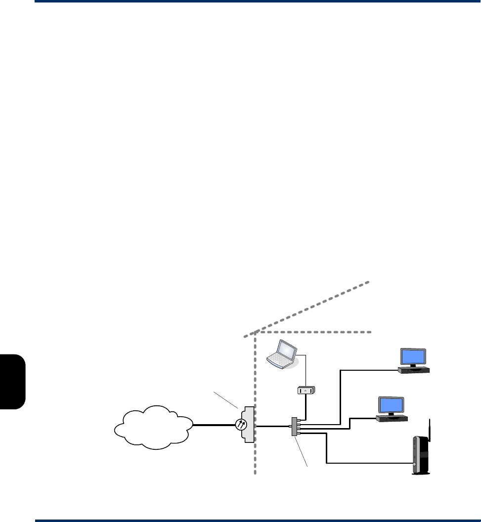
Tech-X Flex User Guide - Firmware v06.50 Tech-X Flex® (NG2)
7-32
Intro Overview Wi-Fi Ethernet System IP/Video MoCA RF Specs
• It is shielded.
• Typically, an existing coaxial network already interconnects the video devices within the home, which
are a primary target for broadband services.
• Compared to wireless networks, wire-based networks are generally faster, more secure, and more
reliable.
The MoCA 1.1 and 2.0 standards allow up to 16 nodes per network. MoCA 1.1 allows a theoretical
maximum data rate of 270 Mbps between devices and MoCA 2.0 allows a theoretical maximum of 800
Mbps, although actual data rates are normally lower due to line attenuation. For more information on how
the network controls data rates, see MoCA physical layer on page 7-36.
Note that the term “MoCA” may be used to describe the organization that promotes the transport
technologies or the technologies themselves. For the remainder of this document, unless otherwise
specified, “MoCA” is used to describe the transport standard, not the organization. For more information
on MoCA as an organization, visit www.mocalliance.org.
7.7.2 Example physical MoCA network
For a brief explanation of MoCA, consider the following figure and the description that follows. This figure
shows a fiber-to-the-premises (FTTP) architecture where an optical network terminal (ONT) terminates
the fiber and converts network traffic to MoCA, where it is fed into the home.
Figure 7-21 Example MoCA network, fed by an FTTP architecture
ONT
(Fiber to MoCA)
Provider
network/ISP Fiber Coax/
MoCA Coax/
MoCA
Coax splitter
MoCA STB
MoCA STB
MoCA router
MoCA to
Ethernet
Cat 5 /
Ethernet
Preliminary issue - Limited distribution only!

Tech-X Flex® (NG2) Tech-X Flex User Guide - Firmware v06.50
7-33
Intro
Overview
Wi-Fi
Ethernet
System
IP/Video
MoCA
RF
Specs
MoCA operates using a hierarchical or “branching tree” physical topology with a “root” at the first coaxial
splitter, with additional devices (or nodes) connected to one or more secondary splitters as “branches”
distributed throughout the premises. The resulting logical network then appears as a mesh of point-to-
point connections established between each of the nodes. This differs from a switched Ethernet network
using twisted pair/Cat-5 copper, which typically uses a hub, switch, or similar device at a junction to
manage traffic flow. In a MoCA network, all nodes are logically interconnected on a single mesh,
including the router.
On a MoCA network, a single node acts as the network coordinator (NC), with all other devices acting as
member nodes. Using time-division multiplexing, the NC manages traffic flow by coordinating data
transmission from all network nodes, including itself. In order to transmit, a node must request a time
slot(s) from the NC which then periodically sends out a “schedule” of what node can transmit and when.
Any MoCA-compliant device can act as the NC and typically a network is configured to automatically
select the NC for optimal performance. Automatic NC selection also ensures that the network continues
to operate if the current NC fails or is removed from the network.
A single coaxial network can carry more than one MoCA network using different frequencies (or
channels) to differentiate the two. A common use of multiple channels is to allow a WAN and a LAN to
exist on the same physical cable. In the Figure 7-21 example, all nodes are interconnected by a single
coaxial tree, with a single cable connected to the router. Therefore, both the provider WAN (wide area
network) and the residential LAN (local area network) must operate on the same cables using different
channels. Each node must be configured to request admission to the proper network, with the router
configured to join both. Note that because the LAN and WAN are separate MoCA networks, they both
have their own NCs, which may be the same node (the router) or may be different nodes.
Despite the physical interconnectivity of this example network, the logical network concept operates
identically to other networks with respect to member nodes. In the Figure 7-21 example, the WAN
consists of the ONT and router only and the LAN consists of the router and all other devices except the
ONT. Even though every node has both the LAN and WAN signals at its coaxial port, only the router is
part of both networks. For example, the ONT will have the LAN signal available at its coaxial port, but it
will be configured to join the WAN only at its respective MoCA channel.
Figure 7-21 also shows an Ethernet-based connection to a computer, linked to the MoCA network by a
MoCA/Ethernet bridge. While set-top boxes (STBs) and other multimedia devices are typically MoCA-
ready and plug directly into the coaxial cable, home computers use twisted pair-based Ethernet or other
protocols for networking. Because an IPTV provider may supply broadband internet access as well, a
computer must interface with the MoCA network via the bridge (or perhaps a wireless connection) in
order to reach the provider WAN.
NOTE: As with any networking technology, there are a wide variety of configurations and devices
available which may differ from this diagram. Consult Other MoCA network examples/scenarios
on page 7-34 or a network engineer for more information about MoCA and the types of
networks you may encounter.
Preliminary issue - Limited distribution only!
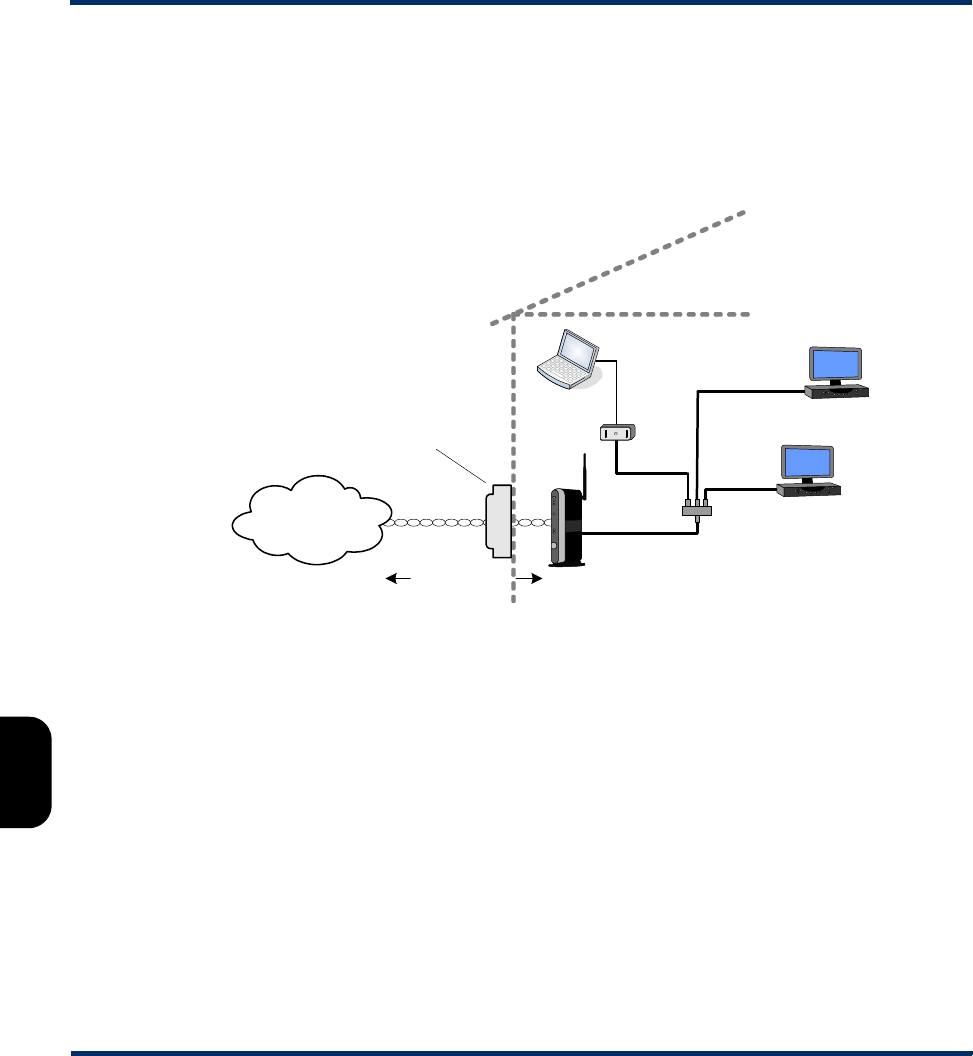
Tech-X Flex User Guide - Firmware v06.50 Tech-X Flex® (NG2)
7-34
Intro Overview Wi-Fi Ethernet System IP/Video MoCA RF Specs
7.7.3 Other MoCA network examples/scenarios
Aside from the FTTP-based architecture shown in Figure 7-21 on page 7-33, MoCA implementations
may take other forms, especially with regard to the type of network used by the provider to deliver
broadband services to the premises. For example, the following figure shows a typical DSL-based MoCA
architecture:
Figure 7-22 Example MoCA network, fed by a DSL architecture
In this case, the residential gateway (RG) is connected directly to the telephone company twisted pair,
where the DSL signal and provider WAN are terminated. The RG has a coaxial port for the residential
LAN side of the network and therefore serves as an interface between DSL and MoCA. With regard to
testing with the unit, the important item to note is that the cable only carries a single MoCA network (the
LAN). While the unit can join a MoCA network on any channel, testing on the WAN in this type of network
is not applicable, as it may be in the architecture shown in Figure 7-21 on page 7-33.
For broadband service architectures delivered by a cable TV provider, the diagram might be similar to
Figure 7-22 on page 7-35, except replaced by a DOCSIS network upstream from the RG. Again, this type
of architecture would use MoCA to transport the LAN, but not the provider WAN.
Note that other alternatives are possible, beyond those presented in this document. Consult a network
engineer or administrator for more information on the type of network(s) you are likely to test with the
unit.
Telco NID
Provider
network/ISP
Twisted pair
Coax/
MoCA
DSL modem /
RG
MoCA STB
MoCA STB
MoCA to
Ethernet
Cat 5 /
Ethernet
DSL
Preliminary issue - Limited distribution only!

Tech-X Flex® (NG2) Tech-X Flex User Guide - Firmware v06.50
7-35
Intro
Overview
Wi-Fi
Ethernet
System
IP/Video
MoCA
RF
Specs
7.7.4 MoCA functional overview
A MoCA network is designed for self-maintenance and dynamic adjustment for optimal performance.
The following sections briefly describe the physical and media access layers (PHY and MAC,
respectively), along with some details on the communications involved with network maintenance,
especially as related to testing with the MoCA module. For more information, including descriptions of
traffic not mentioned here, see the technical specifications related to MoCA.
MoCA physical layer
At the physical layer, a MoCA network operates on one of several available RF channels between 500
and 1650 MHz, with each channel spanning 50 MHz (MoCA 1.1) or 100 MHz (MoCA 2.0) in its spectrum
usage. The available channels are organized into bands, with only one channel per band permitted for
use on any physical network. In some cases, though, two channels from different bands may be active
on the same cable to allow the transport of two different logical networks, such as the case where a WAN
and LAN are operating on the same cable. In this case, there are effectively two different MoCA networks
on the same cable. For more information, see Example physical MoCA network on page 7-32.
MoCA uses the adaptive constellation multi-tone (ACMT) technique to transform layer 2 (MAC) data and
control frames, as well as physical layer probe frames, into QAM symbols. These symbols are modulated
onto a channel's subcarrier frequencies to create a serial bitstream. The MoCA specifications allow a
subcarrier to be modulated using any mode of QAM, up to 256-QAM which carries 8 bits per symbol
(MoCA 1.1) or up to 1024 QAM which carries 10 bits per symbol (MoCA 2.0). The actual maximum bits
per symbol that any given subcarrier can carry, however, depends upon the physical conditions which
affect the ability of the line to reliably transport the subcarrier frequencies.
For any coaxial network, the physical path between any two devices can vary widely due to line length,
reflections, splitter configuration, and other conditions. Aside from overall attenuation, these
characteristics also have a different effect on different frequencies, even subcarrier frequencies that are
close on the spectrum. To account for these variances, member nodes regularly send physical-layer
“probe” messages to each other to evaluate the physical network between them. Using this messaging,
the nodes are able to construct an appropriate “modulation profile” for transmission to each other, which
includes how many bits that each subcarrier should attempt to carry (known as the bit-loading). A profile
may determine that some subcarriers can not reliably carry the maximum number of bits and mandate a
lower number, or even restrict the transmission on certain subcarrier frequencies altogether. In any given
network, each node has a separate profile for communication with each other node, which maximizes
network performance.
With its statistics-gathering features, the MoCA module can produce bit-loading graphs that plot how
effectively subcarriers are carrying data to and from the unit. For more information, see Node Stats page
(MoCA Network Statistics) on page 7-13.
Preliminary issue - Limited distribution only!

Tech-X Flex User Guide - Firmware v06.50 Tech-X Flex® (NG2)
7-36
Intro Overview Wi-Fi Ethernet System IP/Video MoCA RF Specs
MoCA data link layer
MoCA defines a MAC (media access control) protocol that determines how nodes may access the
shared media to transmit/receive Ethernet frames. It specifies two general types of MAC layer frames:
•Control frames - Frames that contain MoCA network management messaging
•Data frames - Frames that contain the end-user application data (internet, IPTV, etc.)
The two primary types of control frames are bandwidth requests and media access plans (MAPs).
Because the meshed nature of the logical network allows only one node to transmit at any given time, the
network coordinator (NC) must coordinate all transmission by all nodes. When a node wants to transmit,
it sends a bandwidth request to the NC. In turn, the NC regularly broadcasts MAPs which are effectively
precise schedules about which node can transmit and when. Not only does a MAP tell a node when it
should transmit, it also allows the target node to know when to expect the transmission.
Another type of media access control is the admission request and associated negotiations. When a new
device is connected to the network, it must request admission to the network from the NC and then
complete a set of qualifying steps. It finds the appropriate channel and the NC location by a mechanism
known as beacons, which the NC also regularly broadcasts. Because admission control is only initiated
by a new device, no admission control frames would be expected on a stable network.
7.7.5 Common coaxial cable problems that affect MoCA
The following cable-related issues can affect MoCA performance:
• A fault in the cable, such as a short circuit or other condition which may affect the electrical continuity.
Because a MoCA network is physically interconnected, a critical short-circuit can prevent the
transport of all MoCA signaling to all devices, including the WAN and the LAN (see Example physical
MoCA network on page 7-32).
• A bad connection, perhaps caused by corrosion, a loose connector, or poor connector crimping.
• Attenuation due to the excessive use of cable splitters or the general splitter configuration. In
particular, the presence of “splitter jumps,” where two nodes communicate through the outputs of one
or more splitters, can have an impact on channel characteristics. For example:
Figure 7-23 Splitter jump, through a single splitter
Splitter jump
In Out
Preliminary issue - Limited distribution only!

Tech-X Flex® (NG2) Tech-X Flex User Guide - Firmware v06.50
7-37
Intro
Overview
Wi-Fi
Ethernet
System
IP/Video
MoCA
RF
Specs
• Excessive cable length
• A powered signal amplifier on the network that restricts the passage of frequencies in the MoCA
spectrum
Ultimately, any condition that increases line attenuation will decrease the reach and performance of
MoCA.
7.7.6 About multiple MoCA versions on a single network
MoCA 2.0 provides backwards compatibility with MoCA 1.1, such that a MoCA 2.0-compliant node can
operate at MoCA 1.1. Furthermore, if a network has both 2.0-compliant and 1.1-compliant nodes, the
2.0-compliant nodes can use 2.0 to communicate with each other, while using 1.1 for the other nodes.
The following notes are applicable to this supported scenario:
• Because of the time-division nature of MoCA transmissions, only a single node transmits at any given
time. Therefore, at any given instant, only a single MoCA protocol is actively in use, which facilitates
the use of multiple versions on a single network.
• If a 2.0 node is transmitting to a another 2.0 node, it uses the 2.0 channel bandwidth of 100 MHz,
along with any other 2.0 characteristics. Otherwise, the 1.1 bandwidth of 50 MHz is used.
• The NC must be a 2.0 node to allow any 2.0 communications. Otherwise, all nodes must use 1.1 at
all times.
Preliminary issue - Limited distribution only!

Tech-X Flex User Guide - Firmware v06.50 Tech-X Flex® (NG2)
7-38
Intro Overview Wi-Fi Ethernet System IP/Video MoCA RF Specs
Preliminary issue - Limited distribution only!
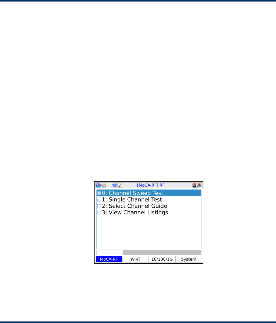
Tech-X Flex® (NG2) Tech-X Flex User Guide - Firmware v06.50
8-1
8: MoCA/RF - RF Testing
This section describes the RF-specific functions of the combined MoCA/RF module. This module adds:
• Signal strength measurements, for both analog and digital (QAM) video channels.
• For digital signals, common measurements such as MER and BER, along with a constellation
diagram analysis tool.
For specific function details, see:
•Channel Sweep Test on page 8-2
•Single Channel Test on page 8-4
•Select Channel Guide on page 8-7
•View Channel Listings on page 8-7
Figure 8-1 RF main testing menu
8.1 Important notes on handling the module
See Handling the MoCA/RF module on page 2-30.
Preliminary issue - Limited distribution only!
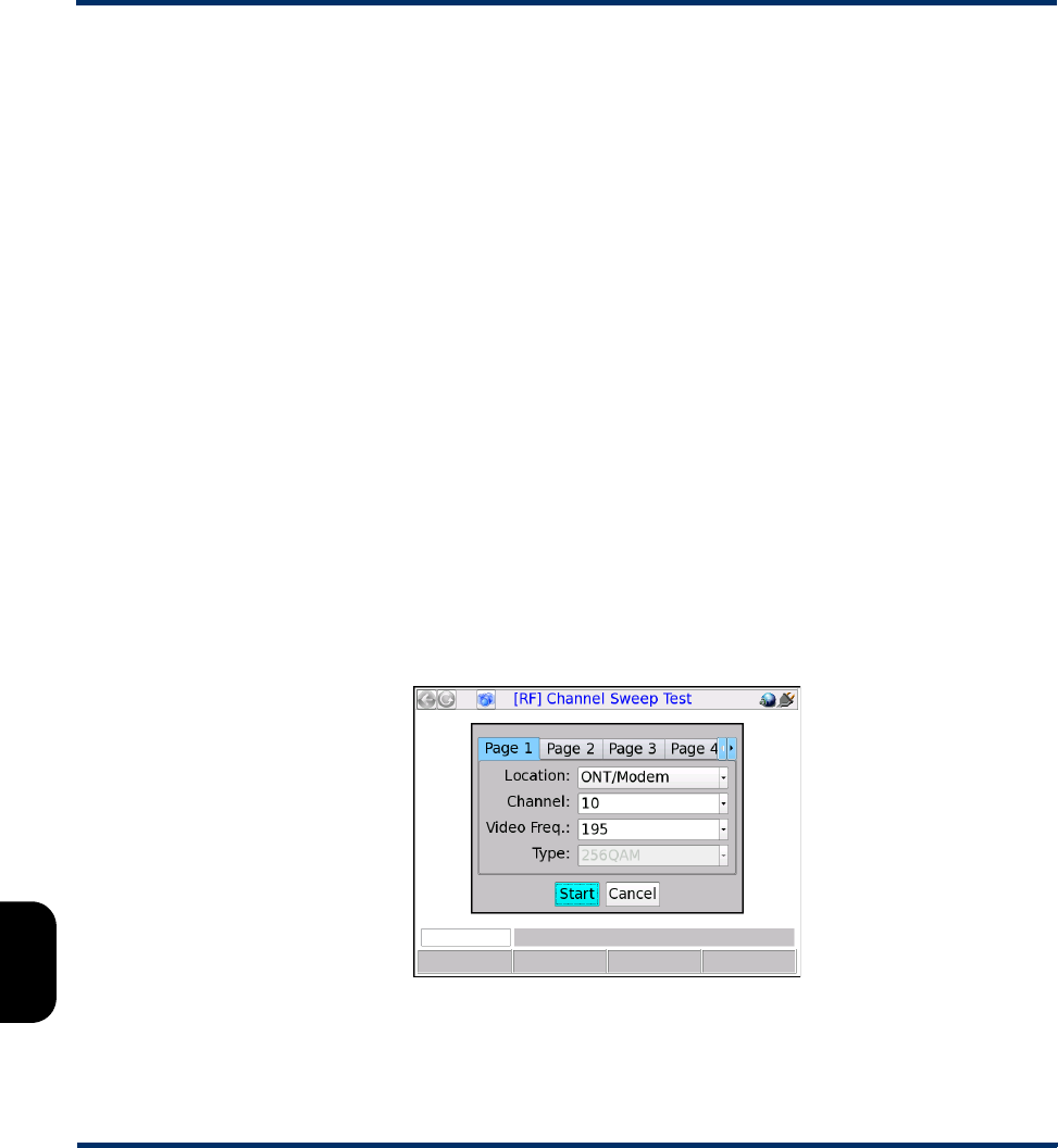
Tech-X Flex User Guide - Firmware v06.50 Tech-X Flex® (NG2)
8-2
Intro Overview Wi-Fi Ethernet System IP/Video MoCA RF Specs
8.2 Channel Sweep Test
The Channel Sweep Test (available from the main RF menu) provides RF measurements for up to 12
channels on the wire, serving as a batch test of a group of channels. The results produced for each
channel are a subset of the information produced when a Single Channel Test is run. For a description
of these results, see Channel testing measurements/results on page 8-12.
8.2.1 Channel Sweep Test setup
In the test setup, each tab represents a single channel to include with the test. Tabs without data
populated are ignored. Note the following:
• All channels share a common Location which determines the set of thresholds to use for flagging
test results. This field must be set in the first tab. For more information, see Thresholds on page 8-23.
• In each tab, you can specify a channel either by channel number or by frequency/type. To select
channels by number, you must have an active channel guide on the unit which allows the unit to
correlate the number with a frequency and type. Otherwise, channel frequencies and types can be
specified directly. In general, the use of a guide is preferred. For more information on channel guides,
see View Channel Listings on page 8-7.
Additionally, note the following about channel selection:
– The unit will reject any frequencies that are not valid according to the current EIA channel table on
the unit.
– If the unit can correlate a frequency with a channel in the active channel guide (if applicable), it
will automatically select the Type and disable the input field.
Figure 8-2 Channel Sweep Test setup
Preliminary issue - Limited distribution only!
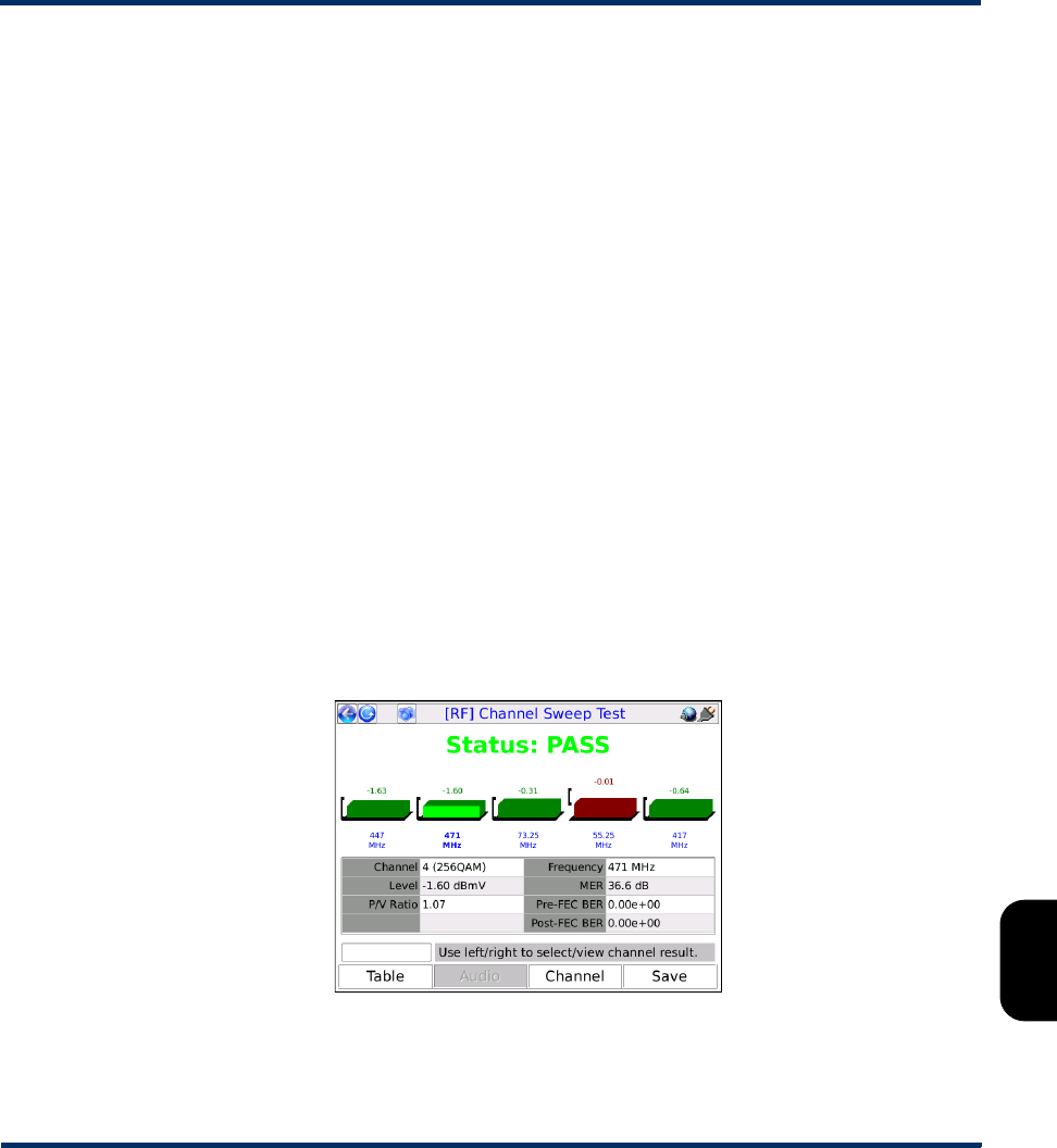
Tech-X Flex® (NG2) Tech-X Flex User Guide - Firmware v06.50
8-3
Intro
Overview
Wi-Fi
Ethernet
System
IP/Video
MoCA
RF
Specs
8.2.2 Channel Sweep Test results
For the results, note the following:
• See Channel testing measurements/results on page 8-12 for detailed results descriptions.
• In the graphical view, the table at the bottom shows details for the selected channel only, identified by
a lighter color on the bar graphs. Use the left/right arrow keys to change the selection.
NOTE: The PASS/FAIL indication also applies to the selected channel only. See Channel testing
measurements/results on page 8-12 for more information on pass vs. fail.
• In the graphs and tables, any result that has violated a configured threshold is colored red. See
Thresholds on page 8-23 for more information.
• Results are presented only for channels to which the unit could successfully synchronize.
• All results for all channels are measured and calculated one time only. The test does not perform
repeated measurements like the Single Channel Test.
• Results for out-of-band (OOB) channels include power measurements only. For more information,
see About out-of-band (OOB) channel support on page 8-18.
•Use the F1 key (Table / Graph) to toggle between the graphical and general tabular views. The
tabular view shows signal power measurements only, for all tested channels.
• While in the graphical view, use the F2 key (Audio / Video) to toggle between audio and video signal
measurements.
•Use the Channel shortcut (F3) to launch the Single Channel Test (see Single Channel Test on
page 8-4).
Figure 8-3 Channel Sweep Test results, with the second channel selected
Preliminary issue - Limited distribution only!

Tech-X Flex User Guide - Firmware v06.50 Tech-X Flex® (NG2)
8-4
Intro Overview Wi-Fi Ethernet System IP/Video MoCA RF Specs
8.3 Single Channel Test
The Single Channel Test (available from the main RF menu) provides measurements on a single
specified channel.
8.3.1 Single Channel Test setup
The test initiates immediately with no setup parameters. All test parameters are configured in the results
screen.
8.3.2 Single Channel Test results
By default, the test runs continuously and operates based on parameters that can be configured in the
results screen. See below for further information on selecting the channel for analysis and other setup
parameters. For more information on the RF-related measurements in this screen, see Channel testing
measurements/results on page 8-12.
Figure 8-4 Single Channel Test results, with a violation related to signal power
Note the following:
• While actively running, the test resamples its measurements periodically with the following effects on
reported results:
– For digital channels, the data used to calculate BER (Pre-FEC and Post-FEC) and MER is added
to all previous data and the results are recalculated, adding to their precision. See Digital channel
test results on page 8-15 for more information.
– All other results reflect the instantaneous values from the most recent measurement interval.
Preliminary issue - Limited distribution only!
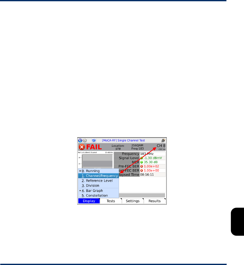
Tech-X Flex® (NG2) Tech-X Flex User Guide - Firmware v06.50
8-5
Intro
Overview
Wi-Fi
Ethernet
System
IP/Video
MoCA
RF
Specs
• If the test cannot synchronize with the channel because the power is too low, it will still produce a
power level reading; however, you should be aware that the channel may not exist and the power
measurement may represent noise only.
• Results for analog channels include power measurements only. Additionally, note that:
– The unit measures the “video” frequency only, not the audio.
– The unit does not tune or lock onto the channel by any method. It simply measures power at the
video frequency.
• Results for out-of-band (OOB) channels include power measurements only. For more information,
see About out-of-band (OOB) channel support on page 8-18.
• In the graph and table, any result that has violated a configured threshold is colored red.
Furthermore, if a single results parameter violates a threshold, the test status is reported as FAIL.
See Channel testing measurements/results on page 8-12 for more information.
The screen provides a set of important setup controls that can be operated while a test is ongoing, either
by:
•Using the Display menu (F1), or
• Using the arrow keys on the unit keypad. When using the arrow keys, use the:
– Left and right arrows to shuffle between controls
– Up and down arrows to change the current setting
Figure 8-5 Display menu
On the display, only a single control can have the focus at any given time. Therefore, for reliable behavior
when you use the arrow keys, you should remain aware of which control has the current focus. The
following table describes these controls.
Preliminary issue - Limited distribution only!

Tech-X Flex User Guide - Firmware v06.50 Tech-X Flex® (NG2)
8-6
Intro Overview Wi-Fi Ethernet System IP/Video MoCA RF Specs
Table 8-1 Test display controls
Additionally:
•The Tests menu (F2) provides quick access to any other top-level test supported by the module.
•The Settings menu (F3) provides quick access to the module settings areas normally found under
the System menu.
Display control Function
Running (Display > Running) Pauses and restarts a continuously-running test.
Channel/Frequency (Display > Channel/Frequency) Sets the channel for analysis. You should
specify:
A Channel number or designation, which refers to a channel in the active
channel guide (see View Channel Listings on page 8-7).
-or-
The frequency and type of a valid EIA channel. These fields available to test
channels that are not in the active channel guide and/or to run tests without a
guide imported to the unit. Generally, the use of a guide is preferred, when
feasible. If the unit locates the frequency in the active guide, it will automatically
populate the Channel field. Additionally, note the following:
• The unit will reject any frequencies that are not valid according to the current
EIA channel table on the unit.
• If the unit can correlate a frequency with a channel in the active channel
guide (as applicable), it will automatically select the Type and disable the
input field.
Location (Not available in the Display menu) Specifies the threshold set to apply. The
thresholds control pass/fail and coloring aspects, but otherwise do not affect
how measurements are calculated. For more information, see Thresholds on
page 8-23.
Reference Level
Division
(Display > Reference Level and Display > Division) Control the layout of bar
graphs (see Bar graph and power measurement notes on page 8-13).
Bar
Graph/Constellation
(Display > Bar Graph and Display > Constellation) Toggles between the bar
graph display and the constellation diagram., for digital channels only For more
information on the constellation diagram, see About QAM and the constellation
graph on page 8-18).
Preliminary issue - Limited distribution only!

Tech-X Flex® (NG2) Tech-X Flex User Guide - Firmware v06.50
8-7
Intro
Overview
Wi-Fi
Ethernet
System
IP/Video
MoCA
RF
Specs
8.4 Select Channel Guide
This function allows you to select the active channel guide, if multiple guides are present on the unit. The
unit uses the channel guide to verify valid frequencies and to correlate frequencies with channel
numbers, in various areas of testing.
Note that:
• Only one guide may be active at any given time.
• You can view the channel listings in the active guide at any time with the View Channel Listings
function (see View Channel Listings on page 8-7).
• You can download new and/or updated guides to the unit as required (see Download RF Channel
Guide(s) on page 8-23).
8.5 View Channel Listings
From the main RF menu, View Channel Listings allows you to view two channel tables on the unit:
• The standard listing of TV channels and their associated frequencies (see EIA CATV tab on
page 8-7)
• The channel guide currently active on the unit, which should reflect the architecture under test (see
Lineup tab on page 8-8)
8.5.1 EIA CATV tab
This tab displays a list of channel numbers/designations and their associated frequencies supported by
the module tuner, according to EIA standards[4]. Channels in the active channel guide (see Lineup tab on
page 8-8) should each reference a channel from this list, which is how the unit determines the
frequency(ies) for testing. The information in this tab is fixed according to the firmware package on the
unit and cannot be changed by end users. For a listing of these channels, see Supported channels and
frequencies on page 8-27.
Column Description
CH Channel number or designation. Note the following:
• This is not the number displayed in test setup and results screens.
Rather, it is the number that should be referenced by a channel in
the active channel guide (Lineup tab on page 8-8), as applicable.
• Out-of-band (OOB) channels, if present, typically appear with an
OOB designation rather than a number.
Preliminary issue - Limited distribution only!
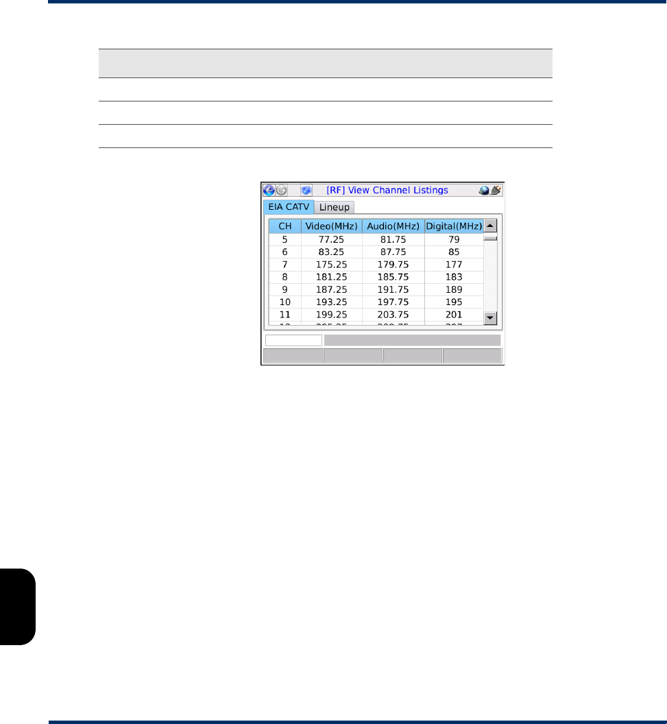
Tech-X Flex User Guide - Firmware v06.50 Tech-X Flex® (NG2)
8-8
Intro Overview Wi-Fi Ethernet System IP/Video MoCA RF Specs
Figure 8-6 EIA CATV tab
8.5.2 Lineup tab
This tab displays the customer-specific channel lineup configured for the unit, as found in the active
channel guide. During testing, when a channel is selected by number, the unit looks up that number in
this lineup, then uses the remaining information in the channel entry to complete the testing request.
Note that:
• If the unit has multiple guides imported, you can select the active guide with the Select Channel
Guide function (see Select Channel Guide on page 8-7).
• You can download new and/or updated guides to the unit as required (see Download RF Channel
Guide(s) on page 8-23).
• If no channel guide is present or the active channel guide is not correctly formatted, this function will
fail. For more information on the required file format, see Channel guide file format and general
handling notes on page 8-23.
Video Video carrier frequency, for analog channels.
Audio Audio carrier frequency, for analog channels.
Digital Center carrier frequency for digital channels.
Column Description
Preliminary issue - Limited distribution only!
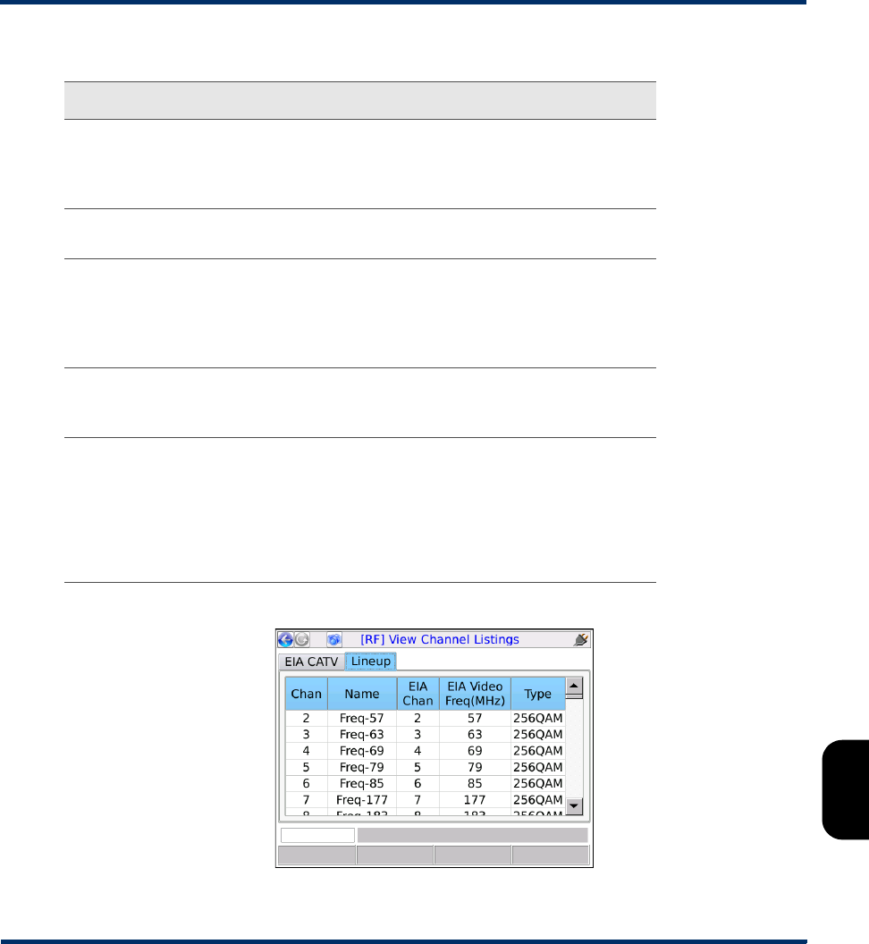
Tech-X Flex® (NG2) Tech-X Flex User Guide - Firmware v06.50
8-9
Intro
Overview
Wi-Fi
Ethernet
System
IP/Video
MoCA
RF
Specs
Figure 8-7 Lineup tab
Column Description
Chan Channel number or designation for the lineup. This
number/designation is used in test setup and results screens, as
applicable. For example, when you specify a channel for a Single
Channel Test, you should specify this value.
Name Channel name or abbreviation, for informational purposes within
the unit testing and results screens.
EIA Chan Channel number/designation from the standard list (see EIA CATV
tab on page 8-7) that this lineup number references. During
testing, the unit looks up frequency and channel type information
for the channel using this number. It must be specified exactly as it
appears in the configured EIA list.
EIA Video
Freq
Channel frequency (or video frequency, for analog channels),
drawn from the standard list based on the EIA Chan number (see
EIA CATV tab on page 8-7).
Type Channel type, which the unit uses to determine how testing should
be conducted on the channel. Valid values include:
•64QAM (digital)
•256QAM (digital)
•Analog
•QPSK (required for out-of-band (OOB) channels
Preliminary issue - Limited distribution only!

Tech-X Flex User Guide - Firmware v06.50 Tech-X Flex® (NG2)
8-10
Intro Overview Wi-Fi Ethernet System IP/Video MoCA RF Specs
8.6 Close-Out Test Script
The Close-Out Test Script is a tool for running a series of Channel Sweep tests at various locations
within a subscriber premises, recording the results in a single file that can be transferred from the unit
following the testing. The intent is to produce a composite collection of results representing the service at
a single subscriber location.
The specific channels to test during the sweep are specified in the System menu. For more information,
see RF Script settings on page 8-26.
8.6.1 General procedure for running the Close-Out Script
The transfer of a results file requires configuration of the Admin Port on the base unit. Because it is
normally not feasible to maintain this configuration while moving between rooms to test the RF network,
the following general sequence of events should be followed:
• Launch the script and perform measurements in all desired locations (see Launching the Close-Out
Script on page 8-10).
• Exit the script. If presented with results handling options, select the option to keep or preserve results.
• Connect the Admin Port to a network that is able reach the computer to which the results should be
transferred. (System > Admin Port, see Admin Port on page 5-5 for more information).
• Launch the script again, selecting the option to FTP results, rather than to run the script again. When
untransferred results are remaining on the unit from a previous script run, the unit will produce a
prompt with the FTP option the next time the script is launched.
For more information on results handling and FTP, see RF Script settings on page 8-26 and Close-Out
Script results management and transfer on page 8-12.
8.6.2 Launching the Close-Out Script
NOTE: Before running the script, you should be sure that the primary script settings are configured
correctly (see RF Script settings on page 8-26).
When the script is launched, the unit may present a screen with options for handling results from a
previous script run, if it detects results from a previous run that have not been transferred yet. Until
successfully transferred from the unit or otherwise purged, the results from a previous script remain on
the unit and cause this prompt to appear, providing the following options:
Preliminary issue - Limited distribution only!
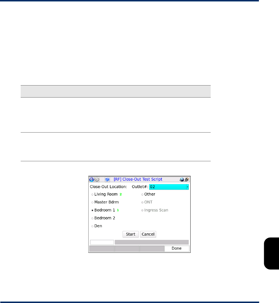
Tech-X Flex® (NG2) Tech-X Flex User Guide - Firmware v06.50
8-11
Intro
Overview
Wi-Fi
Ethernet
System
IP/Video
MoCA
RF
Specs
•Purge - Removes all results from the previous script run and proceeds to the script page.
•Keep - Proceeds to the script page to run a new Close-Out Script and appends any new results to the
previous results set.
•Proceed to FTP - Skips the script testing functions and proceeds directly to the FTP page (see
Close-Out Script results management and transfer on page 8-12).
Note that similar options are presented when you exit the script.
Once the script is fully launched, the setup screen allows you to select the following:
Figure 8-8 Close-Out Script setup
When you click Start, the test runs according to the configured settings and displays a results screen
similar to the Channel Sweep test (see Channel Sweep Test results on page 8-3). At this point, you can:
Setting Description
Close-Out
Location
The room within the premises where the current iteration of testing
should occur. It is assumed that the unit has been physically
connected to a coaxial outlet within that location. Note that each
location will display the total number of outlets tested for that
location as testing progresses.
Outlet The outlet number, within the selected location. This field may be
useful if a room has multiple outlets which require testing. During
the testing process, the unit only permits a single test run at any
given outlet number for a specific room.
Preliminary issue - Limited distribution only!

Tech-X Flex User Guide - Firmware v06.50 Tech-X Flex® (NG2)
8-12
Intro Overview Wi-Fi Ethernet System IP/Video MoCA RF Specs
•Select Next Test to return to the setup screen and run another iteration at a different location.
•Select Done to exit the test and prepare for the transfer of the results (see Close-Out Script results
management and transfer on page 8-12).
8.6.3 Close-Out Script results management and transfer
The script is designed to store results from the previous script run, ready for transfer via FTP to an
external computer after testing is complete. Normally, the FTP process is performed independently
following script testing. For more information on general testing flow, see General procedure for running
the Close-Out Script on page 8-10
Once initiated, the onscreen prompts lead you through the FTP steps, noting the following:
•An Admin Port should be configured with valid, routable IP information before attempting the
transfer. The FTP action requires the unit to be properly networked with the target server via this port.
• If a target server is unavailable, the script allows you to exit with the option whether or not to discard
saved results. If you choose to retain results, you will have the option to attempt the transfer again
when the script is launched the next time.
• Results files contain a complete set of measurement results for each channel measured during each
interval. In a results file, each set of results is preceded by a header that indicates the location and
outlet number for the respective test.
• Once a results file is successfully transferred, the unit no longer produces any prompts related to
those results, such as purge and transfer prompts. The next test begins a new set of results. Note
that all results files remain on the unit indefinitely where they can be viewed, deleted, and/or
transferred with the Record Manager. For more information on the Record Manager, see Record
Manager on page 5-1.
• During the FTP action, any file on the server with the same name as a file on the unit will be
overwritten.
• For more information on setting up an FTP server on a remote computer, see FTP server installation
and setup on page 2-58.
8.7 Measurement descriptions and theory
8.7.1 Channel testing measurements/results
The following information describes the measurements that are produced by the Single Channel Test
and the Channel Sweep Test. Note that these descriptions include common industry standards which
may or may not be applicable to your environment.
Preliminary issue - Limited distribution only!
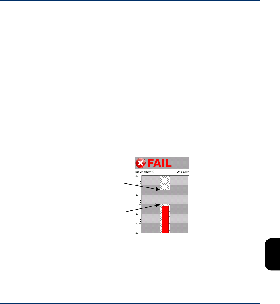
Tech-X Flex® (NG2) Tech-X Flex User Guide - Firmware v06.50
8-13
Intro
Overview
Wi-Fi
Ethernet
System
IP/Video
MoCA
RF
Specs
NOTE: Any individual result that appears in red (including a bar graph) has violated a threshold
configured for the unit. For more information on configuring thresholds, see Thresholds on
page 8-23.
PASS/FAIL status
If any measurement for a channel violates the respective configured threshold, the channel is reported
as FAIL. For the Channel Sweep Test specifically, note that the PASS/FAIL indication refers to the
selected channel only.
For more information on configuring thresholds, see Thresholds on page 8-23.
Bar graph and power measurement notes
Bar graphs are provided for a simple graphical representation of certain measurements, such as power
levels. RF testing includes two basic types of bar graphs.
The first type uses a chart format, with the currently-active thresholds shown as shaded areas. For
example, the following graph shows a power measurement of -1.30 dBmV, slightly below the lower
threshold of 0.0 dBmV and therefore shown as a violation:
Figure 8-9 Bar graph notations
Other important notes about this type of bar graph include:
Lower threshold
(0 dBmV)
Upper threshold
(15 dBmV)
Preliminary issue - Limited distribution only!
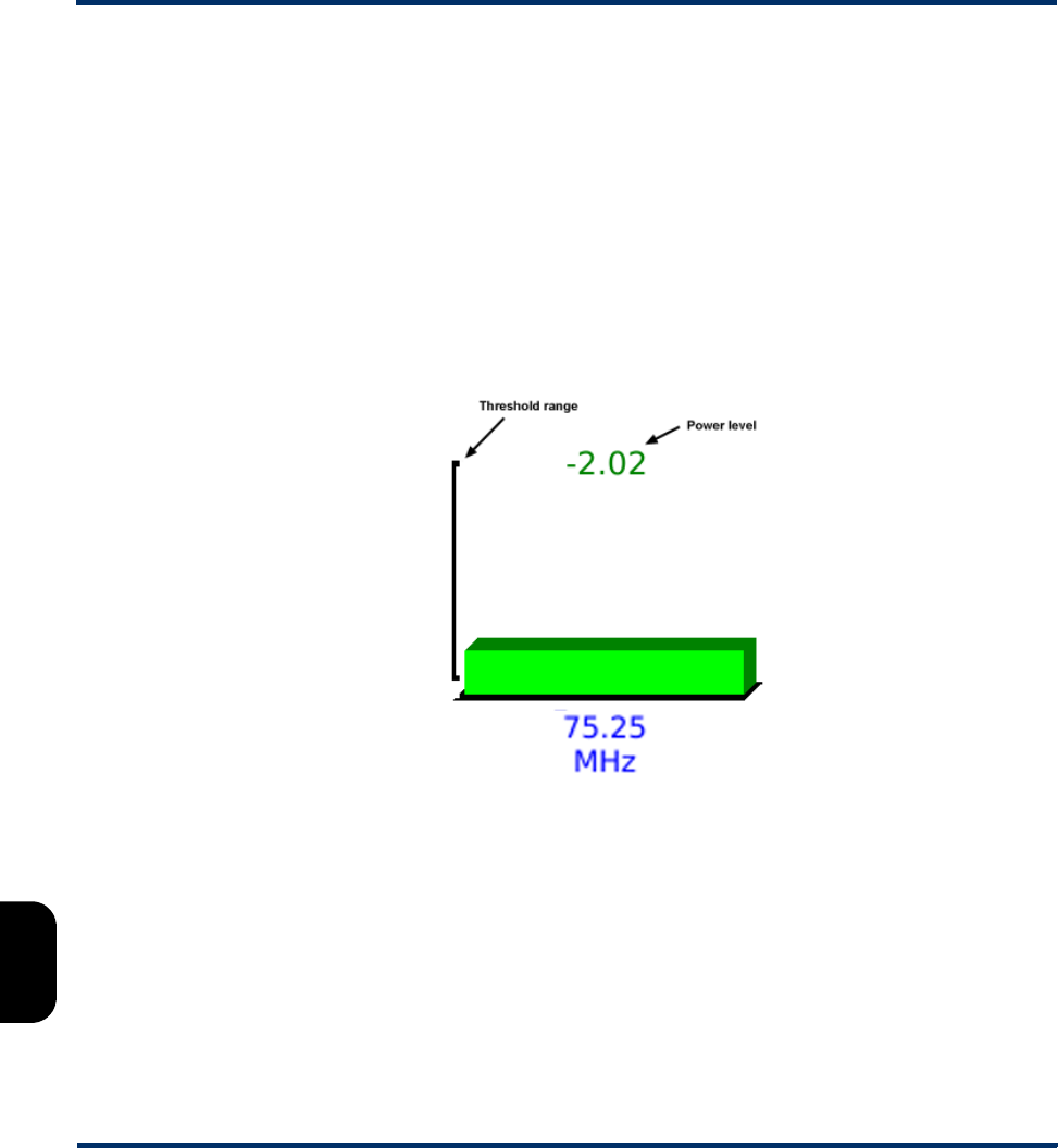
Tech-X Flex User Guide - Firmware v06.50 Tech-X Flex® (NG2)
8-14
Intro Overview Wi-Fi Ethernet System IP/Video MoCA RF Specs
• These graphs include a configurable Reference Level, shown as Ref Lvl (dBmV) in the previous
example. This value sets largest value for the y-axis and allows you to shift the range up and down to
get a better view of the measurement data. In some results screens, the reference level includes the
choice of Auto, with which the unit attempts to center the data automatically.
• Some graphs also include a configurable Division setting, indicated by the 10 dB/div label in the
previous example. This setting indicates the number of respective units in each shaded division on
the graph. In the previous example, the graph contains 6 divisions of 10 dB each, allowing the graph
to span 60 dB. A different Division setting would increase or reduce that span.
The other type of bar graph provides a simple graphical representation of power levels. Above a bar, the
measured power (in dBmV) for the respective signal is displayed. On each bar, a “bracket” provides a
rough estimation of the threshold range configured for the respective power level (see Thresholds on
page 8-23).
Figure 8-10 Bar graph notations
Note that in all cases, the unit is designed to accurately measure power down to -30 dBmV. In some
cases, if a signal below this level is detected and can be measured, the unit will display a value below -
30. If this occurs, it should be noted that the measurement may not be accurate. Furthermore, for very
low measurements, it is possible that the unit is measuring noise on the line, rather than a broadcast
video signal.
Preliminary issue - Limited distribution only!
Tech-X Flex® (NG2) Tech-X Flex User Guide - Firmware v06.50
8-15
Intro
Overview
Wi-Fi
Ethernet
System
IP/Video
MoCA
RF
Specs
Results screen icons and threshold violations
In some results screens where individual results are compared against thresholds, the unit presents
icons that more precisely indicate the outcome of those comparisons. The following table describes
these icons. For more information on thresholds, see Thresholds on page 8-23.
Digital channel test results
Pass.
Indicates a result that exceeded a maximum threshold.
Indicates a result that was lower than a minimum threshold.
Indicates a general failure condition, possibly but not necessarily related to a specific
threshold comparison.
Measurement Description
Frequency Center carrier frequency for the channel.
Preliminary issue - Limited distribution only!

Tech-X Flex User Guide - Firmware v06.50 Tech-X Flex® (NG2)
8-16
Intro Overview Wi-Fi Ethernet System IP/Video MoCA RF Specs
MER
(Modulation error
ratio)
A performance metric for a digitally-modulated signal, typically
used to gauge the reliability of signal transmission. Sometimes
(perhaps erroneously) referred to as a digital carrier-to-noise
measurement, MER is the ratio of the carrier's average symbol
power to the carrier's average error power. A higher number
indicates a better quality of service (that is, less influence from
noise, linear/non-linear distortions, and ingress). Actual
minimums for reliable digital transport may vary according to
architectures and other conditions, but suggested minimums
for an equalized measurement are 23-27 dB for 64-QAM and
28-31 dB for 256-QAM.
The calculation of MER is directly related to the placement of
points on a constellation graph. An “ideal” symbol arrives in the
center of its respective “cell” on the graph, so graphs that
display plots close to their respective centers correspond with
a higher MER. Symbols displayed further from the center
and/or forming “fuzzy” patterns correspond with a lower MER.
Because MER is calculated from sampled bits, the precision
increases with the sample size. Therefore, tests that run
repeated measurements can keep a cumulative data set and
continue to increase the precision of the MER calculation.
For more information about constellation graphs, see About
QAM and the constellation graph on page 8-18.
P/V Ratio or
Peak/Valley
Peak-to-valley ratio, the difference between the highest and
lowest power levels across the frequency band tested, in dB. It
is effectively the highest versus the lowest power level
detected across the bandwidth of a digital channel. On a power
level spectrum graph, a perfect digital signal should appear
“flat” across the frequency band in use by the channel.
However, portions of the bandwidth are normally received at
higher power levels than others due to distortions and
impairments.
Ideally, this number should be as low as possible, with 3 dB
commonly recommended as a maximum. Significant
differences in power levels across the band interfere with the
ability of receiving equipment to decode the modulated signal.
Measurement Description
Preliminary issue - Limited distribution only!

Tech-X Flex® (NG2) Tech-X Flex User Guide - Firmware v06.50
8-17
Intro
Overview
Wi-Fi
Ethernet
System
IP/Video
MoCA
RF
Specs
Pre-FEC
Post-FEC
(Pre- and post-
FEC BER - Bit
error ratio)
The ratio of errored bits to total bits, before and after the unit
applies forward error correction (FEC) with Viterbi and Reed-
Solomon algorithms. The two measurements are intended to
show the signal as it exists on the wire and the signal after a
typical receiver applies FEC, the latter of which more
accurately represents the signal that will be decoded and
processed.
Because BER is calculated from sampled bits, the precision
increases with the sample size. Therefore, tests that run
repeated measurements can keep a cumulative data set and
continue to increase the precision of the BER calculation.
BER measurements may be presented in scientific notation.
For example, a measurement of 1.2e-5 equals 1.2 x 10⁻⁵ or
0.000012, which is equivalent to 12 errored bits per 1,000,000
(1 million) transmitted.
FEC operates using redundant information that is intentionally
transmitted with a digital signal that provides two primary
functions:
• A means of determining when bit errors occur, similar to a
checksum
• A limited ability to reconstruct the original bitstream in the
event of bit errors
Ideally, the post-FEC ratio should be very small, such as zero
to one error per billion bits transmitted (1.0e-9). Small
increases in bit errors can have a rapidly deteriorating effect on
digital video quality, depending on where the errors occur.
Important note about BER and configured thresholds: The
“lower” a BER threshold, the longer it takes the unit to
accumulate enough sample data to accurately display a BER
calculation and indicate threshold violations. For example, if a
BER threshold is set to 1.0e-9, the unit technically requires a
sample set of at least a billion bits to properly detect a
threshold violation and therefore may introduce significant
delay with the presentation of the result.
Measurement Description
Preliminary issue - Limited distribution only!

Tech-X Flex User Guide - Firmware v06.50 Tech-X Flex® (NG2)
8-18
Intro Overview Wi-Fi Ethernet System IP/Video MoCA RF Specs
8.7.2 About out-of-band (OOB) channel support
The unit supports power measurements on OOB channels using the Single Channel Test and the
Channel Sweep Test. An OOB channel is a provider-specific channel typically used for the transfer of
data between a set-top box (STB) and provider equipment, such as the interaction with an on-screen
channel guide. An OOB channel normally uses a non-standard single frequency chosen specifically to
serve the desired purpose without interfering with normal channel frequencies.
To enable testing on OOB channels, you must:
• Have the channel(s) configured in the main channel list (EIA, etc.). The main channel list is fixed on
the unit according to the installed firmware package. For more information, see EIA CATV tab on
page 8-7.
• Have the channel(s) configured in the active channel guide, such that they may be specified for the
Single Channel Test and/or Channel Sweep Test setup. Like any channel, they must be specified
exactly as shown in the active channel guide. For more information, see Lineup tab on page 8-8 and
Download RF Channel Guide(s) on page 8-23.
Only power level measurements are performed on OOB channels. When an OOB channel is tested, no
other results will appear. Furthermore, the unit supports separate pass/fail thresholds for OOB channels,
up to a maximum of two separate channels. For more information, see About out-of-band (OOB) channel
support on page 8-18.
8.7.3 About QAM and the constellation graph
QAM (Quadrature Amplitude Modulation) is one of many methods for transporting digital data over
analog waveforms such as RF sine waves. With QAM, the fundamental technique of representing digital
bits is through amplitude modulation of the analog waves, where a prescribed set of amplitudes are
assigned to different binary digits.
As an example of amplitude modulation, consider an amplitude scheme that is segmented into four
different levels. This type of scheme can present one of four digits (that is, two bits) with each wave cycle,
with the following hypothetical wave modulated with a binary “10”:
Figure 8-11 Hypothetical RF waveform representing a binary 10 (decimal 3)
00
01
10
11
Preliminary issue - Limited distribution only!

Tech-X Flex® (NG2) Tech-X Flex User Guide - Firmware v06.50
8-19
Intro
Overview
Wi-Fi
Ethernet
System
IP/Video
MoCA
RF
Specs
With this method of modulation, the strength and consistency of the carrier frequency are critical for
reliable data transmission. For any given scheme, a weaker signal forces the data points closer together,
which decreases the tolerance for error if the waveform peaks do not fall exactly at the expected level.
Conversely, an increase in amplitude “space” with stronger signals allows the use of schemes with a
greater number of data points, increasing the amount of binary data that can be modulated on each wave
cycle.
QAM uses this technique of modulation with one variation: the addition of a second waveform in order to
double the amount of data that can be sent with each cycle. The two waves, known as the “I” and “Q”
signals, travel at a fixed 90 degrees out-of-phase. With each cycle, both waves represent amplitude-
modulated binary numbers which collectively represent a larger set of bits. Continuing with the previous
example of four data points per cycle, the following QAM cycle might represent a binary “1011”:
Figure 8-12 16-QAM cycle showing a 1011-modulated symbol
This particular scheme is known as “16-QAM,” as each modulated cycle (also known as a symbol)
transports a total of four bits, allowing one of 16 different binary numbers to be modulated (0000 - 1111).
Other QAM schemes such as 64-QAM and 256-QAM operate in a similar fashion, except that they
contain more amplitude data points. For example, 64-QAM defines eight data points which allows each
wave to individually carry a binary number between 000 - 111 (three bits) per cycle. Collectively, then, the
I and Q signals transport six bits per symbol, a binary 000000 - 111111 (0 - 63 in decimal notation).
A constellation diagram is a common means of graphically representing a QAM scheme. These
diagrams use a grid to indicate each potential binary number possible per symbol, using the x- and y-
axes to represent the amplitude data points of the I and Q signals, respectively. For example, the
following constellation diagram represents 16-QAM:
00
01
10
11
I-signal
(10)
Q-signal
(11)
Preliminary issue - Limited distribution only!

Tech-X Flex User Guide - Firmware v06.50 Tech-X Flex® (NG2)
8-20
Intro Overview Wi-Fi Ethernet System IP/Video MoCA RF Specs
Figure 8-13 16-QAM constellation diagram
Aside from a basic chart of binary numbers supported by a QAM scheme, a constellation graph is also a
useful means of visually presenting the quality of an actual QAM signal, especially with respect to the
consistency of amplitude measurements and their intended binary representations. Using a graph in this
manner, the exact center of each “square” is designated as the point where the I and Q signals fall
exactly upon a prescribed data point (that is, an expected amplitude), when the symbol is sampled and
demodulated. For example, the following figure shows a “perfect” symbol that would be plotted as follows
in the “1011” square:
Figure 8-14 The plot of a “perfectly” modulated symbol
Consider, however, a symbol that appears as follows at the point of demodulation:
Figure 8-15 Imperfect amplitude levels
0000 0100 1100 1000
0001 0101 1101 1001
0011 0111 1111 1011
0010 0110 1110 1010
Q
I
00
01
10
11
I-signal
(10)
Q-signal
(11)
Preliminary issue - Limited distribution only!
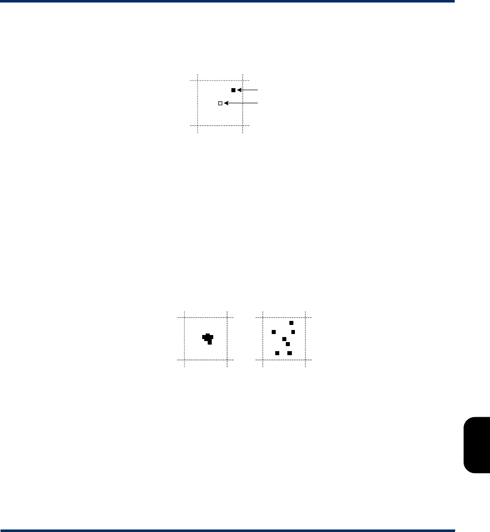
Tech-X Flex® (NG2) Tech-X Flex User Guide - Firmware v06.50
8-21
Intro
Overview
Wi-Fi
Ethernet
System
IP/Video
MoCA
RF
Specs
In this case, the variation of the actual amplitudes from the expected levels for perfect modulation would
cause the symbol to be plotted off-center. Because the I and Q signals both deviate from the expected
amplitude, the plot is pushed away from center on both axes:
Figure 8-16 Imperfect symbol plot
When the unit draws the constellation graph, it samples a small subset of symbols on the selected
channel and plots them in the respective square. In summary, then:
• The more closely the symbol plots are clustered at the center of each square, the better the
performance of the QAM signal overall. As real-world perfection is not possible, a tight cluster close
to the center generally represents the best performance possible.
• If the amplitude of one or both signals deviates so much the original binary number is misinterpreted
as another, bit errors occur. A constellation diagram that shows widely dispersed points indicates a
signal where this is more likely to occur. A diagram with closely-clustered points indicates the
opposite, where the reliability of the signal is strong and bit errors/ambiguities are less likely.
• The overall amount of deviation from the ideal is a key factor in the calculation of MER. An MER
measurement, therefore, is fundamentally a numerical summarization of a constellation graph.
Figure 8-17 Symbol plot examples
Any nature of impairment (such as noise) can cause degradation of an amplitude-modulated symbol and
cause scattered plots on a constellation graph. Certain types of impairments tend to show a recognizable
signature on the graph. The following figures show some of these common impairments:
Actual plot
Ideal location
Symbol cluster
on a good signal
Symbol cluster
on a poor signal
Preliminary issue - Limited distribution only!
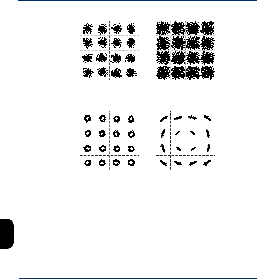
Tech-X Flex User Guide - Firmware v06.50 Tech-X Flex® (NG2)
8-22
Intro Overview Wi-Fi Ethernet System IP/Video MoCA RF Specs
Figure 8-18 Common impairment signatures on the constellation graph
The first three normally indicate outside interference on the physical medium. A phase disturbance or
mismatch between the I and Q signals is usually caused by a malfunction of the modulation equipment.
8.8 System menu settings/controls (for RF)
Under System > System/Module Settings > MoCA-RF Module > RF, the following areas are available
that control RF module settings:
•Download RF Channel Guide(s) on page 8-23
•Thresholds on page 8-23
•RF Script settings on page 8-26
Moderate noise impairment Severe noise impairment
RF interference I/Q signal phase disturbance
Preliminary issue - Limited distribution only!

Tech-X Flex® (NG2) Tech-X Flex User Guide - Firmware v06.50
8-23
Intro
Overview
Wi-Fi
Ethernet
System
IP/Video
MoCA
RF
Specs
8.8.1 Download RF Channel Guide(s)
(Select System > System/Module Settings > MoCA-RF Module > RF > Download RF Channel
Guide(s))
This function is used to transfer channel guide files from a remote computer to the unit using FTP. For
more information, see:
•Channel guide file format and general handling notes on page 8-23 for file format information
•FTP connection parameters on page 2-59 for general tips on preparing for the FTP transaction
For general information about channel guide functionality, see Lineup tab on page 8-8.
Channel guide file format and general handling notes
A channel guide file must be in text-based comma-separated values (CSV) format, with four fields on
each line representing the four columns shown in the Lineup tab (see Lineup tab on page 8-8). The
following example shows the four supported types of entries for analog and digital channels, including
out-of-band (OOB) channels:
10,ABC,35,Analog
11,NBC,36,64QAM
12,CBS,37,256QAM
OOB1,OutOfBand,OOB,QPSK
Note that:
• The fourth field (channel type) is case-sensitive and must be formatted exactly as shown.
• The file must have a *.txt extension.
For a sample channel guide file, please contact Spirent. Additionally, note the following about channel
guide transfer:
• On the FTP server computer, the file(s) to transfer must be placed in the folder associated with the
FTP user account that you intend to use.
• The FTP operation will transfer any file in the server folder with a *.txt extension. Therefore, any
file you want to transfer must use that extension. If any filename in the server folder matches a file
already on the unit, the file on the unit will be overwritten.
8.8.2 Thresholds
(Select System > System/Module Settings > MoCA-RF Module > RF > Thresholds)
This screen provides access to:
Preliminary issue - Limited distribution only!
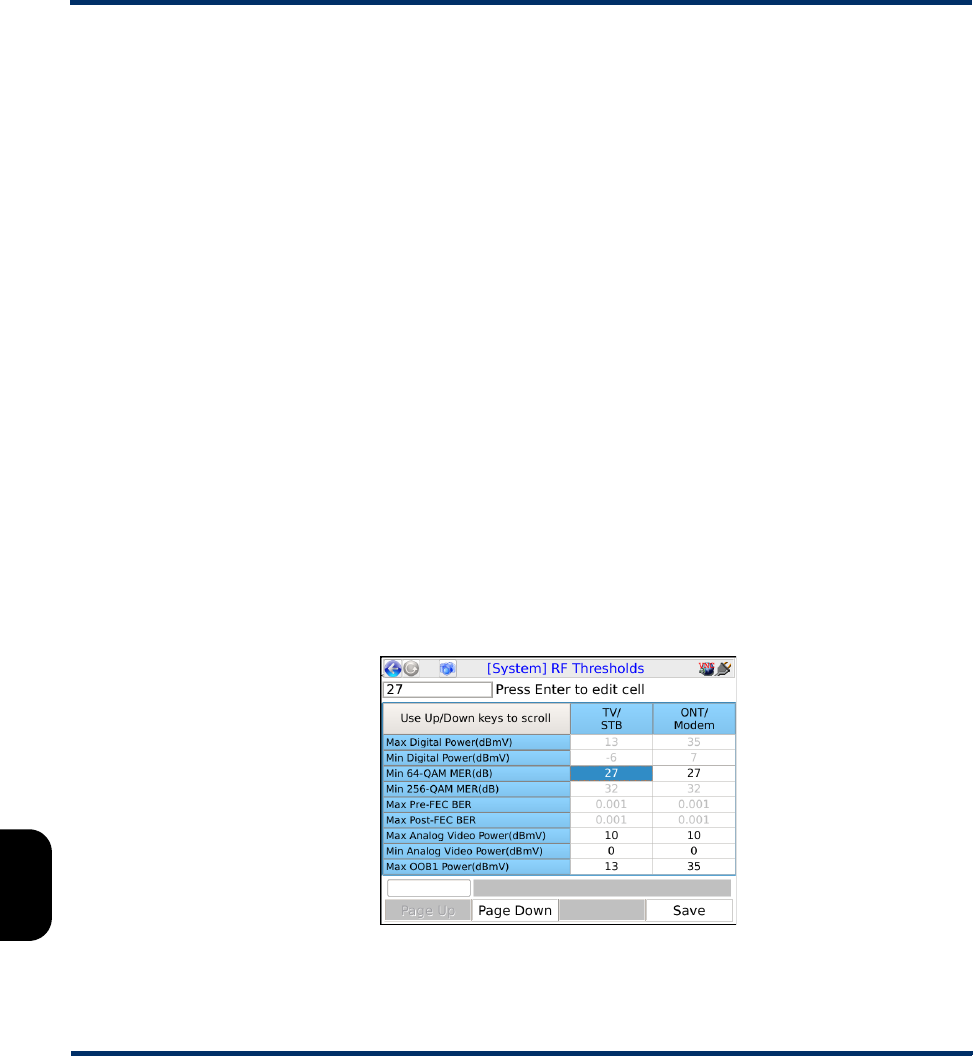
Tech-X Flex User Guide - Firmware v06.50 Tech-X Flex® (NG2)
8-24
Intro Overview Wi-Fi Ethernet System IP/Video MoCA RF Specs
•View/Edit Thresholds on page 8-24 - Allows you to view and edit individual thresholds on the unit
•Download Thresholds on page 8-25 - Allows you to set all thresholds as a batch by importing a
threshold settings file
View/Edit Thresholds
(Select System > System/Module Settings > MoCA-RF Module > RF > Thresholds > View/Edit
Thresholds)
The settings in the Thresholds screen control the following:
•The coloring of test results - Any individual result that violates its respective threshold is colored
red
•The overall pass/fail evaluation for a channel - For any channel tested, if any result threshold is
violated, the channel test is considered a failure overall
The Thresholds screen allows two independent set of thresholds to be configured, labeled “TV/STB”
and “ONT/Modem.” These labels are intended as a convenience for the common practice of maintaining
two different threshold sets for testing at the respective locations. However, you may specify any
applicable thresholds for either set and test with them at any location. For more information on specifying
the threshold set to use during testing, see Channel Sweep Test setup on page 8-2 and Single Channel
Test setup on page 8-4.
For out-of-band (OOB) channels, the unit supports thresholds for minimum and maximum power levels
only. For more information on OOB channels, see About out-of-band (OOB) channel support on
page 8-18.
Figure 8-19 Threshold screen
Preliminary issue - Limited distribution only!

Tech-X Flex® (NG2) Tech-X Flex User Guide - Firmware v06.50
8-25
Intro
Overview
Wi-Fi
Ethernet
System
IP/Video
MoCA
RF
Specs
Some thresholds include both a minimum and maximum setting, while others a minimum or maximum
only. For example, a BER threshold requires a maximum only, as the minimum value (that is, a “perfect”
condition) is always zero.
NOTE: If a threshold is not editable, it has been configured as such in the threshold file imported to the
unit. For more information, see Download Thresholds on page 8-25.
Download Thresholds
As an alternative to editing thresholds directly on the unit, you can download a thresholds file to set all
thresholds as a batch. This action completely overwrites all existing thresholds on the unit.
For more information on the parameters required for the FTP transaction, see FTP connection
parameters on page 2-59. The remainder of this section describes the required threshold file format.
A threshold file uses a simple CSV format with lines in the following format:
thld_name,TV_STB_value,ONT_Modem_value
For example:
Max Digital Power(dBmV),13,30
Min Digital Power(dBmV),-6,7
It must have the following filename:
RFThresholds.dat
Note the following:
• You should never change a threshold name (first field), otherwise the threshold will become
unrecognizable and the unit will use a default instead.
• You can precede any line with an exclamation point (!) to restrict the setting from editing onboard the
unit, for example:
!Min Digital Power(dBmV),13,30
In this case, the minimum digital power will be viewable on the unit, but will not be editable. Note that
this condition cannot be undone except by importing another thresholds file to the unit.
Preliminary issue - Limited distribution only!

Tech-X Flex User Guide - Firmware v06.50 Tech-X Flex® (NG2)
8-26
Intro Overview Wi-Fi Ethernet System IP/Video MoCA RF Specs
Supported threshold ranges
8.8.3 RF Script settings
(Select System > System/Module Settings > RF Video Module > RF Script Settings)
The settings in this area apply to the Close-Out Test Script (see Close-Out Test Script on page 8-10)
and include:
Table 8-2 General tab
Threshold Range
Max Digital Power
Min Digital Power
-30 to 30 dBmV
Min 64-QAM MER 24 to 29 dB
Min 256-QAM MER 28 to 33 dB
Max Pre-FEC BER
Max Post-FEC BER
0.0000000010 to 0.001
Max Analog Video Power
Min Analog Video Power
-30 to 30 dBmV
Minimum and maximum OOB channel
power levels
-35 to 35 dBmV
Setting Description
Close-Out
Saved
Results
Format
Controls the format of the results file to be transferred from the
unit, as follows:
•XML-1 - Produces a results file in XML format that adheres to a
Spirent-provided schema.
•TXT - Produces a results file in a general text format without
XML markup.
Close-Out
Test
Channels
Channels to test during each iteration of the script. Up to five
channels may be specified and each channel must match a
channel configured in the active channel guide, similar to the
normal Channel Sweep test (see Lineup tab on page 8-8 and
Download RF Channel Guide(s) on page 8-23).
Preliminary issue - Limited distribution only!

Tech-X Flex® (NG2) Tech-X Flex User Guide - Firmware v06.50
8-27
Intro
Overview
Wi-Fi
Ethernet
System
IP/Video
MoCA
RF
Specs
Table 8-3 FTP tab
8.9 Supported channels and frequencies
The module tuner supports the following EIA cable TV channels. Note that OOB channels are not listed:
Setting Description
System
Name
A name under which all other FTP settings will be stored when you
select Save. This feature is a convenience that allows you to store
the profiles of multiple target servers and retrieve them later by
selecting the name. To create a new profile, select [Create New]
from the list and follow the prompts.
Server IP
Port
User ID
Pswd
Ping Before
Transfer
Information about the FTP server on the target computer, to which
results are transferred following a script run. For more information,
see FTP connection parameters on page 2-59.
Ch. # A. video
(MHz)
A. audio
(Mhz)
Digital
(MHz) Ch. # A. video
(MHz)
A. audio
(Mhz)
Digital
(MHz)
255.2500 59.7500 57.0000 81 565.2500 569.7500 567.0000
361.2500 65.7500 63.0000 82 571.2500 575.7500 573.0000
467.2500 71.7500 69.0000 83 577.2500 581.7500 579.0000
577.2500 81.7500 79.0000 84 583.2500 587.7500 585.0000
683.2500 87.7500 85.0000 85 589.2500 593.7500 591.0000
7175.2500 179.7500 177.0000 86 595.2500 599.7500 597.0000
8181.2500 185.7500 183.0000 87 601.2500 605.7500 603.0000
9187.2500 191.7500 189.0000 88 607.2500 611.7500 609.0000
10 193.2500 197.7500 195.0000 89 613.2500 617.7500 615.0000
11 199.2500 203.7500 201.0000 90 619.2500 623.7500 621.0000
12 205.2500 209.7500 207.0000 91 625.2500 629.7500 627.0000
13 211.2500 215.7500 213.0000 92 631.2500 635.7500 633.0000
Preliminary issue - Limited distribution only!

Tech-X Flex User Guide - Firmware v06.50 Tech-X Flex® (NG2)
8-28
Intro Overview Wi-Fi Ethernet System IP/Video MoCA RF Specs
14 121.2625 125.7625 123.0000 93 637.2500 641.7500 639.0000
15 127.2625 131.7625 129.0000 94 643.2500 647.7500 645.0000
16 133.2625 137.7625 135.0000 95 91.2500 95.7500 93.0000
17 139.2500 143.7500 141.0000 96 97.2500 101.7500 99.0000
18 145.2500 149.7500 147.0000 97 103.2500 107.7500 105.0000
19 151.2500 155.7500 153.0000 98 109.2750 113.7750 111.0000
20 157.2500 161.7500 159.0000 99 115.2750 119.7750 117.0000
21 163.2500 167.7500 165.0000 100 649.2500 653.7500 651.0000
22 169.2500 173.7500 171.0000 101 655.2500 659.7500 657.0000
23 217.2500 221.7500 219.0000 102 661.2500 665.7500 663.0000
24 223.2500 227.7500 225.0000 103 667.2500 671.7500 669.0000
25 229.2625 233.7625 231.0000 104 673.2500 677.7500 675.0000
26 235.2625 239.7625 237.0000 105 679.2500 683.7500 681.0000
27 241.2625 245.7625 243.0000 106 685.2500 689.7500 687.0000
28 247.2625 251.7625 249.0000 107 691.2500 695.7500 693.0000
29 253.2625 257.7625 255.0000 108 697.2500 701.7500 699.0000
30 259.2625 263.7625 261.0000 109 703.2500 707.7500 705.0000
31 265.2625 269.7652 267.0000 110 709.2500 713.7500 711.0000
32 271.2625 275.7625 273.0000 111 715.2500 719.7500 717.0000
33 277.2625 281.7625 279.0000 112 721.2500 725.7500 723.0000
34 283.2625 287.7625 285.0000 113 727.2500 731.7500 729.0000
35 289.2625 293.7625 291.0000 114 733.2500 737.7500 735.0000
36 295.2625 299.7625 297.0000 115 739.2500 743.7500 741.0000
37 301.2625 305.7625 303.0000 116 745.2500 749.7500 747.0000
38 307.2625 311.7625 309.0000 117 751.2500 755.7500 753.0000
39 313.2625 317.7625 315.0000 118757.2500 761.7500 759.0000
40 319.2625 323.7625 321.0000 119 763.2500 767.7500 765.0000
Ch. # A. video
(MHz)
A. audio
(Mhz)
Digital
(MHz) Ch. # A. video
(MHz)
A. audio
(Mhz)
Digital
(MHz)
Preliminary issue - Limited distribution only!

Tech-X Flex® (NG2) Tech-X Flex User Guide - Firmware v06.50
8-29
Intro
Overview
Wi-Fi
Ethernet
System
IP/Video
MoCA
RF
Specs
41 325.2625 329.7625 327.0000 120 769.2500 773.7500 771.0000
42 331.2750 335.7750 333.0000 121 775.2500 779.7500 777.0000
43 337.2625 341.7625 339.0000 122 781.2500 785.7500 783.0000
44 343.2625 347.7625 345.0000 123 787.2500 791.7500 789.0000
45 349.2625 353.7625 351.0000 124 793.2500 797.7500 795.0000
46 355.2625 359.7625 357.0000 125 799.2500 803.7500 801.0000
47 361.2625 365.7625 363.0000 126 805.2500 809.7500 807.0000
48 367.2625 371.7625 369.0000 127 811.2500 815.7500 813.0000
49 373.2625 377.7625 375.0000 128 817.2500 821.7500 819.0000
50 379.2625 383.7625 381.0000 129 823.2500 827.7500 825.0000
51 385.2625 389.7625 387.0000 130 829.2500 833.7500 831.0000
52 391.2625 395.7625 393.0000 131 835.2500 839.7500 837.0000
53 397.2625 401.7625 399.0000 132 841.2500 845.7500 843.0000
54 403.2500 407.7500 405.0000 133 847.2500 851.7500 849.0000
55 409.2500 413.7500 411.0000 134 853.2500 857.7500 855.0000
56 415.2500 419.7500 417.0000 135 859.2500 863.7500 861.0000
57 421.2500 425.7500 423.0000 136 865.2500 869.7500 867.0000
58 427.2500 431.7500 429.0000 137 871.2500 875.7500 873.0000
59 433.2500 437.7500 435.0000 138 877.2500 881.7500 879.0000
60 439.2500 443.7500 441.0000 139 883.2500 887.7500 885.0000
61 445.2500 449.7500 447.0000 140 889.2500 893.7500 891.0000
62 451.2500 455.7500 453.0000 141 895.2500 899.7500 897.0000
63 457.2500 461.7500 459.0000 142 901.2500 905.7500 903.0000
64 463.2500 467.7500 465.0000 143 907.2500 911.7500 909.0000
65 469.2500 473.7500 471.0000 144 913.2500 917.7500 915.0000
66 475.2500 479.7500 477.0000 145 919.2500 923.7500 921.0000
67 481.2500 485.7500 483.0000 146 925.2500 929.7500 927.0000
Ch. # A. video
(MHz)
A. audio
(Mhz)
Digital
(MHz) Ch. # A. video
(MHz)
A. audio
(Mhz)
Digital
(MHz)
Preliminary issue - Limited distribution only!

Tech-X Flex User Guide - Firmware v06.50 Tech-X Flex® (NG2)
8-30
Intro Overview Wi-Fi Ethernet System IP/Video MoCA RF Specs
68 487.2500 491.7500 489.0000 147 931.2500 935.7500 933.0000
69 493.2500 497.7500 495.0000 148 937.2500 941.7500 939.0000
70 499.2500 503.7500 501.0000 149 943.2500 947.7500 945.0000
71 505.2500 510.7500 508.0000 150 949.2500 953.7500 951.0000
72 511.2500 515.7500 513.0000 151 955.2500 959.7500 957.0000
73 517.2500 521.7500 519.0000 152 961.2500 965.7500 963.0000
74 523.2500 527.7500 525.0000 153 967.2500 971.7500 969.0000
75 529.2500 533.7500 531.0000 154 973.2500 977.7500 975.0000
76 535.2500 539.7500 537.0000 155 979.2500 983.7500 981.0000
77 541.2500 545.7500 543.0000 156 985.2500 989.7500 987.0000
78 547.2500 551.7500 549.0000 157 991.2500 995.7500 993.0000
79 553.2500 557.7500 555.0000 158 997.2500 1001.750
0
999.0000
80 559.2500 563.7500 561.0000
Ch. # A. video
(MHz)
A. audio
(Mhz)
Digital
(MHz) Ch. # A. video
(MHz)
A. audio
(Mhz)
Digital
(MHz)
Preliminary issue - Limited distribution only!

Tech-X Flex® (NG2) Tech-X Flex User Guide - Firmware v06.50
9-1
9: Specifications
This section provides detailed information on physical components and specifications of the Tech-X Flex
base unit and modules. Note that:
• Specifications are subject to change.
• If the unit produces a measurement that is beyond a range shown in these specifications, it should be
considered generally valid but not necessarily within the stated accuracy.
9.1 General unit specifications
Table 9-1 Physical specifications
Dimensions (H x W x D) • 8.964 in x 4.208 in x 2.524 in
• 22.77 cm x 10.69 cm x 6.41 cm
Weight 2.0 lb. (0.91 kg)
Display Color LCD with adjustable backlight. 640x480 pixels (VGA)
Case material BAYBLEND FR-3000 HI ABS + PC (POLYCARBONATE)
Rubber components TPU (DESMOPAN 9370A)
LED indicators Sync, Data, Errors, Charge
Communications
interfaces
• 10/100/1G Base-T Ethernet
• IEEE 802.11b/g/n/ac (“Wireless B”, “Wireless G”, “Wireless N”, and
“Wireless AC”) Wi-Fi
• USB 2.0
Test interfaces • 10/100/1G Base-T (x2)
• 802.11b/g/n/ac (wireless)
Preliminary issue - Limited distribution only!

Tech-X Flex User Guide - Firmware v06.50 Tech-X Flex® (NG2)
9-2
Intro Overview Wi-Fi Ethernet System IP/Video MoCA RF Specs
Table 9-2 Power specifications
Table 9-3 Environmental requirements
9.2 Wi-Fi functional area specifications
Table 9-4 Wi-Fi specifications
AC operations Requires external AC adapter/charger. Adapter will charge battery while
unit is in use. Adapter specifications:
•Input - 100 to 240 VAC, 50/60 Hz, 0.8 amps
•Output - 12 VDC, 2.0 amps
Battery type Lithium-ion rechargeable, replacements available from Spirent
Battery life 3-10 hours, depending on use and type of module attached
Battery recharge time 3-4 hours
Maximum power usage 24 watts
Maximum heat
dissipation
9 watts
Operating temperature -0.4 to 131°F (-18 to 55°C)
Storage temperature -4 to 158°F (-20 to 70°C)
Humidity tolerance 5 to 85% RH at +104°F (40°C)
Drop IEC 60068, 68-2-32
Protocol support 802.11b/g/n/ac with WEP, WPS, WPA, or WPA2 security.
Antennas •T5200 - Two internal 802.11b/g/n antennas and three internal 802.11ac
antennas.
•T5300 - Three internal antennas for all Wi-Fi testing (b/g/n/ac), one internal
antenna for Wi-Fi admin, and one internal antenna reserved for spectrum
testing.
Preliminary issue - Limited distribution only!

Tech-X Flex® (NG2) Tech-X Flex User Guide - Firmware v06.50
9-3
Intro
Overview
Wi-Fi
Ethernet
System
IP/Video
MoCA
RF
Specs
9.3 RF functional area specifications
Table 9-5 RF functional area specifications
Frequency (with
latest hardware)
For ATSC 6 GHz channels:
•Tuning range: 50 to 1002 MHz
•Tuning resolution: 62.5 kHz
•Channel bandwidth: 6 MHz
For 8 GHz channels:
•Tuning range: 50 to 860 MHz
•Tuning resolution: 62.5 kHz
•Channel bandwidth: 8 MHz
Analog
measurements
•Power measurement range: -30 to +30 dBmV. For additional information, see
Bar graph and power measurement notes on page 8-13.
•Power level accuracy (audio and video): +/-1.5 dB
•Channel support: EIA/NTSC channels 2 through 135
•Other supported measurements:
– Carrier-to-noise ratio
– Audio-to-video ratio
Digital
measurements
•Power measurement range: -30 to +30 dBmV. For additional information, see
Bar graph and power measurement notes on page 8-13.
•Power level accuracy (multiplex): +/-2.0 dB
•QAM support: 64-QAM and 256-QAM
•MER range
–64-QAM: 15 to 40 dB
–256-QAM: 21 to 40 dB
•MER accuracy: +/-2.0 dB
•BER resolution: Up to 10e-05 (1 error per 100,000 bits) for a single
measurement interval. For tests that make repeated measurements, this
resolution increases indefinitely as the data from additional sample periods is
added.
•Other supported measurements:
– Peak-to-valley ratio
– Constellation diagram
Preliminary issue - Limited distribution only!

Tech-X Flex User Guide - Firmware v06.50 Tech-X Flex® (NG2)
9-4
Intro Overview Wi-Fi Ethernet System IP/Video MoCA RF Specs
9.4 MoCA functional area specifications
Table 9-6 MoCA functional area specifications
9.5 MoCA/RF module compliance
UL® /CSA®61010-1 - Safety Requirements For Electrical Equipment For Measurement, Control, and
Laboratory Use
9.6 FCC compliance statements
•RF exposure - This equipment complies with the FCC RF radiation exposure limits set forth for an
uncontrolled environment. For wireless 802.11b/g/n operation, the highest specific absorption rate
(SAR) value is 0.787 W/kg. Special considerations for 802.11ac transmission apply - see Important
wireless 802.11ac note (T5100 models only) on page 3-2.
•Co-location - This transmitter must not be co-located or operated in conjunction with any other
antenna or transmitter.
•Compliance - This device complies with Part 15 of FCC rules. Operation is subject to the following
two conditions:
1 This device may not cause harmful interference and,
2 This device must accept any interference received, including interference that may cause
undesired operation.
•Operation and installation - This equipment has been tested and found to comply with limits defined
by part 15 of FCC Rules. These limits are designed to provide reasonable protection against harmful
interference when the equipment is operated in a commercial environment. This equipment
generates, uses, and can radiate radio frequency energy and, if not installed and used in accordance
with the manufacturer documentation, may cause harmful interference to radio communications.
Operation of this equipment in a residential area is likely to cause harmful interference in which case
the user will be required to correct the interference at his/her own expense.
•Modifications - Changes or modifications not expressly approved by the party responsible for
compliance could void the user’s authority to operate the equipment.
MoCA standard support MoCA 1.0, 1.1, and 2.0
Preliminary issue - Limited distribution only!

Tech-X Flex® (NG2) Tech-X Flex User Guide - Firmware v06.50
9-5
Intro
Overview
Wi-Fi
Ethernet
System
IP/Video
MoCA
RF
Specs
9.7 IC compliance statements
This device complies with Industry Canada license-exempt RSS standard(s). Operation is subject to the
following two conditions: (1) this device may not cause interference, and (2) this device must accept any
interference, including interference that may cause undesired operation of the device.
Le présent appareil est conforme aux CNR d'Industrie Canada applicables aux appareils radio exempts
de licence. L'exploitation est autorisée aux deux conditions suivantes : (1) l'appareil ne doit pas produire
de brouillage, et (2) l'utilisateur de l'appareil doit accepter tout brouillage radioélectrique subi, même si le
brouillage est susceptible d'en compromettre le fonctionnement.
Preliminary issue - Limited distribution only!

Tech-X Flex User Guide - Firmware v06.50 Tech-X Flex® (NG2)
9-6
Intro Overview Wi-Fi Ethernet System IP/Video MoCA RF Specs
Preliminary issue - Limited distribution only!

Preliminary issue - Limited distribution only!