Spirent Communications FLEX-T5300 Tech-X Flex (NG2) User Manual Tech X Flex Manual
Spirent Communications Inc Tech-X Flex (NG2) Tech X Flex Manual
UserManual.wiki
>
Spirent Communications
>
FLEX-T5300 User Manual
>
User Manual Part 2
Contents
1.
User Manual Part 1
2.
User Manual Part 2
User Manual Part 2
Navigation menu
Upload a User Manual
Namespaces
Wiki Guide
HTML
PDF
Info
Views
User Manual
Discussion / Help
Navigation

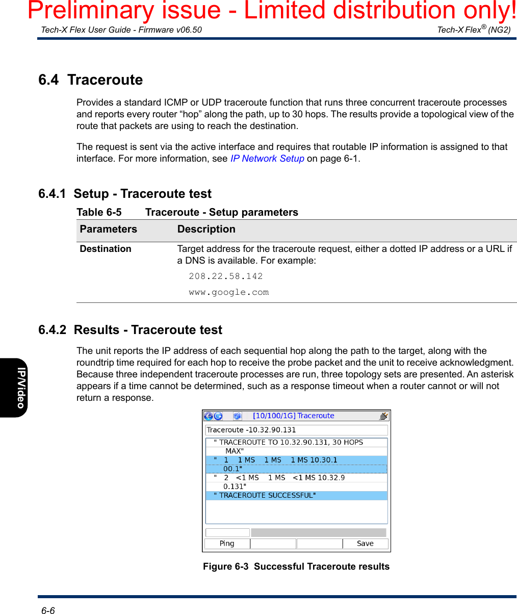

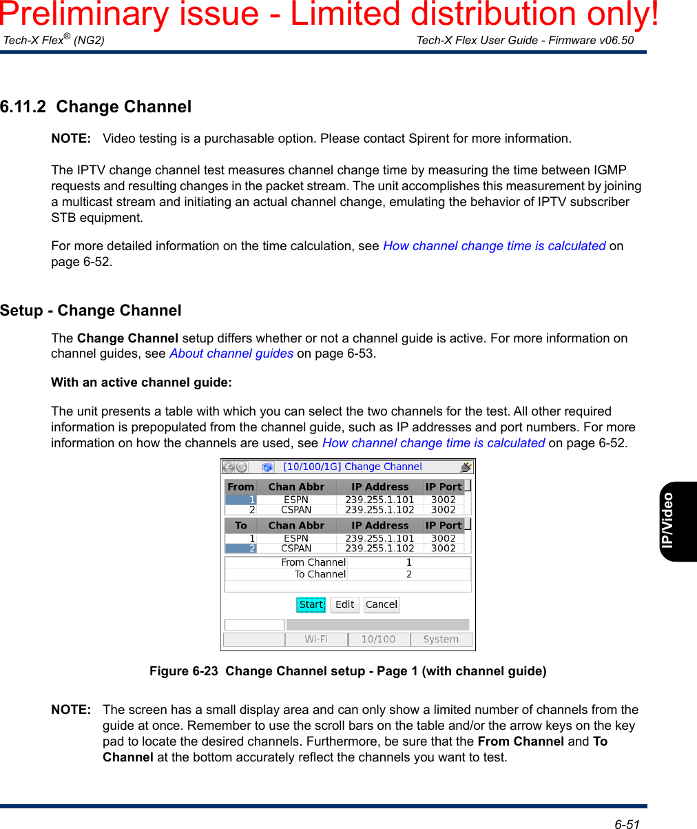
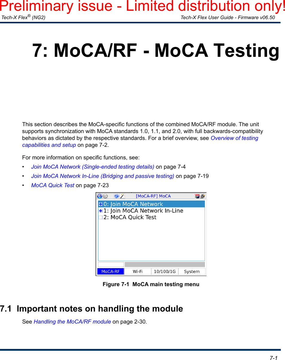
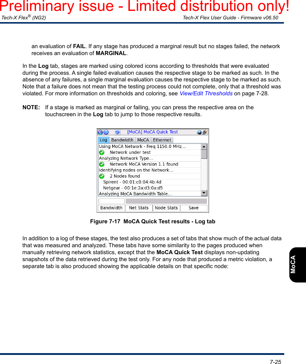
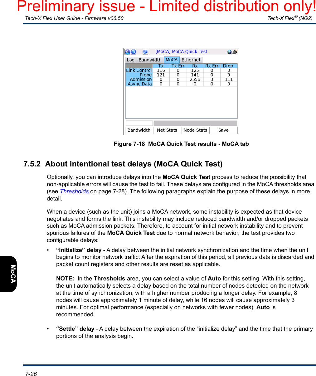
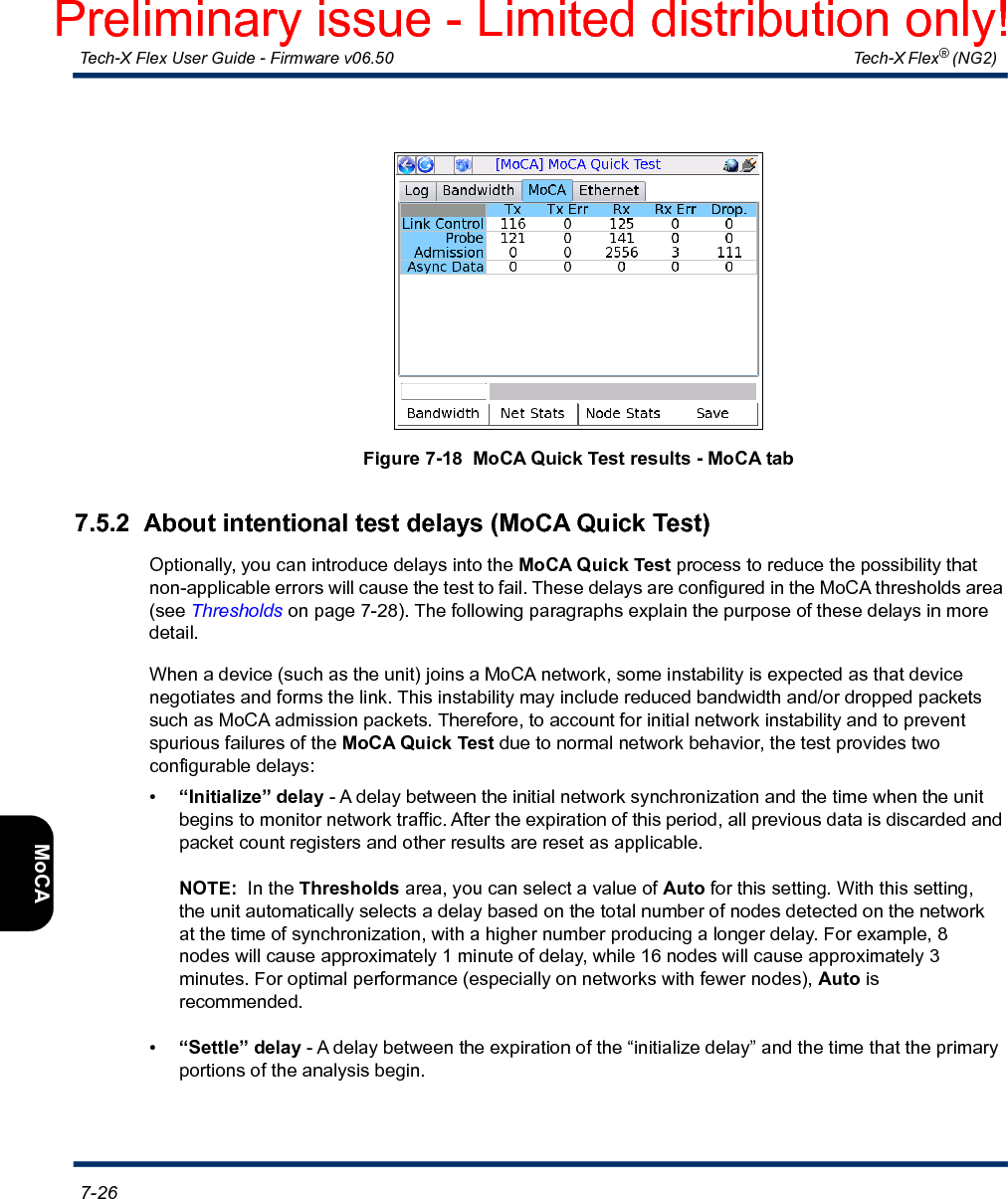
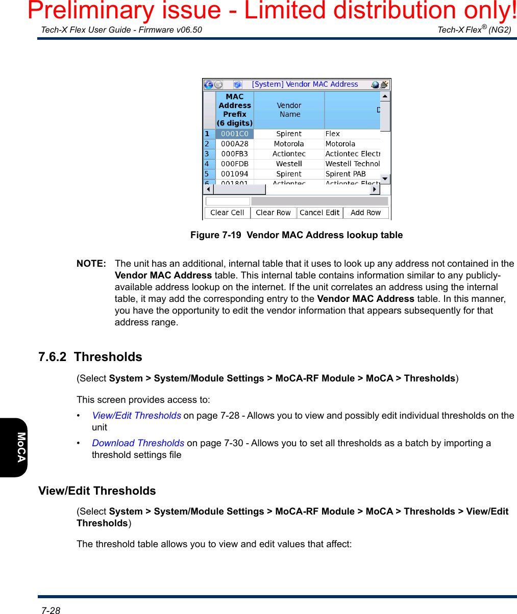
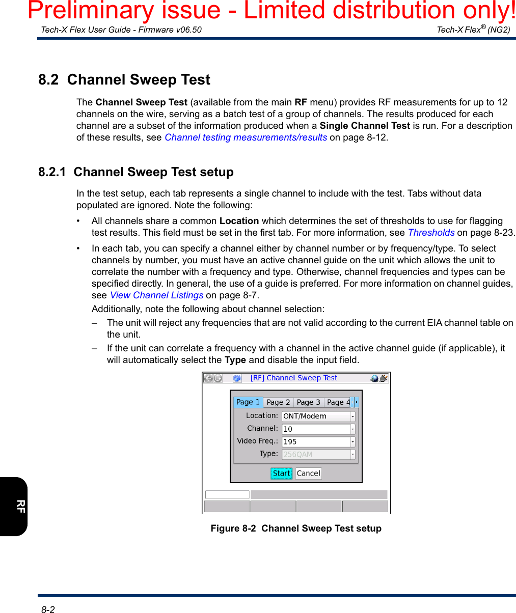
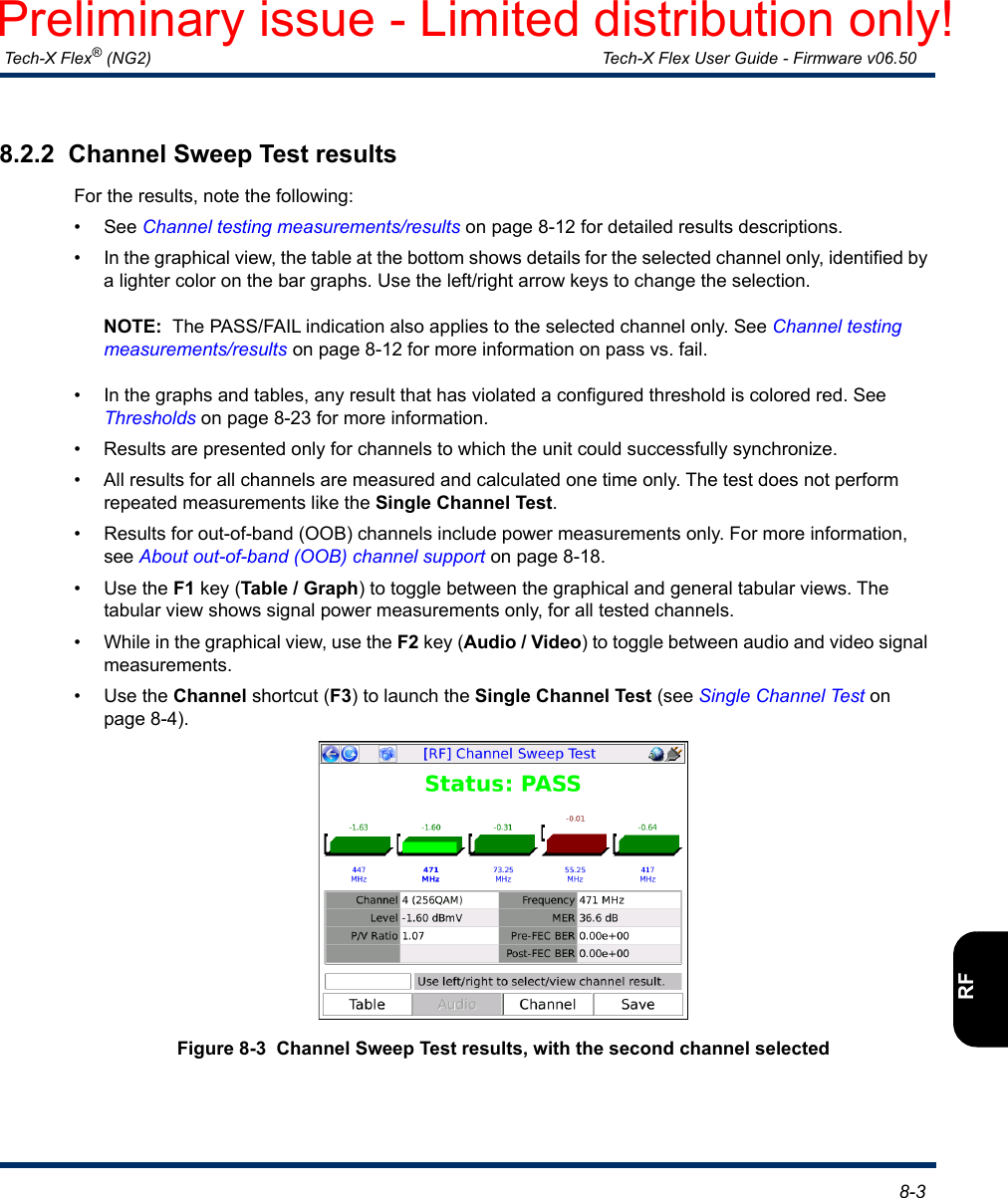
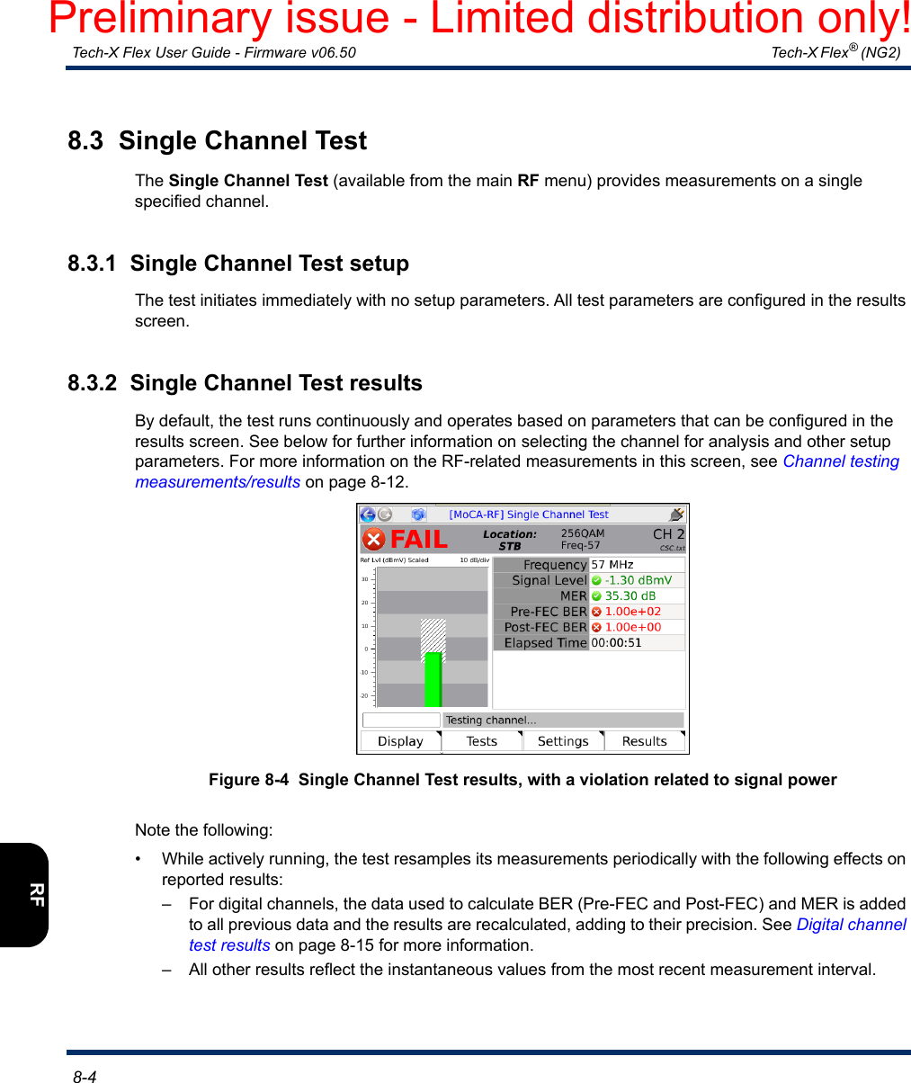
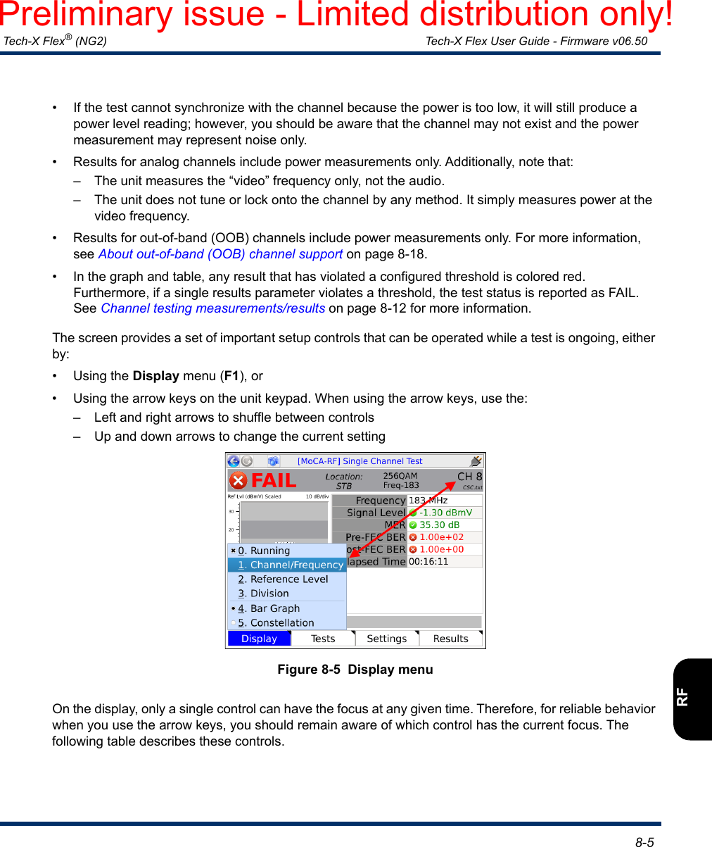
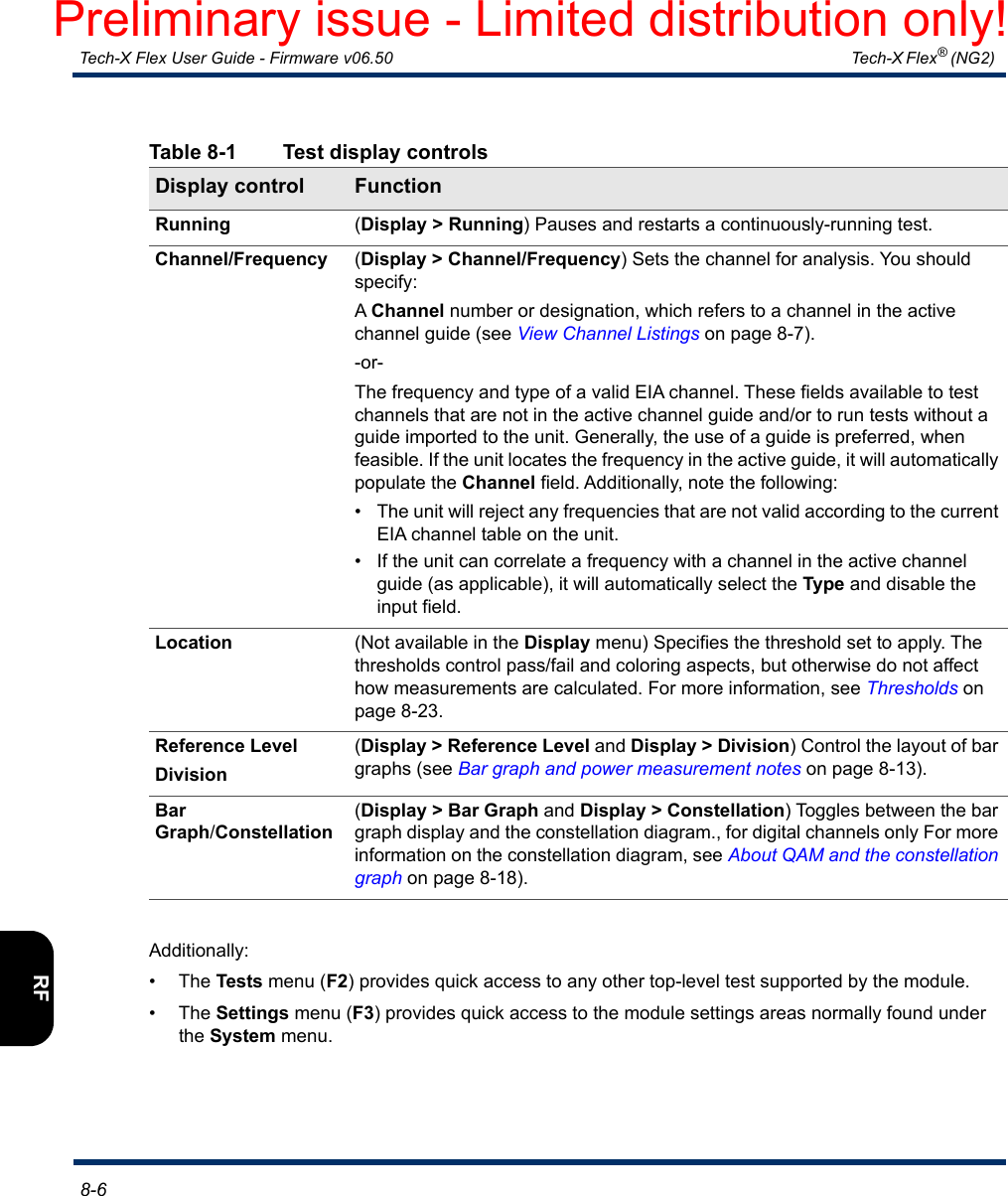
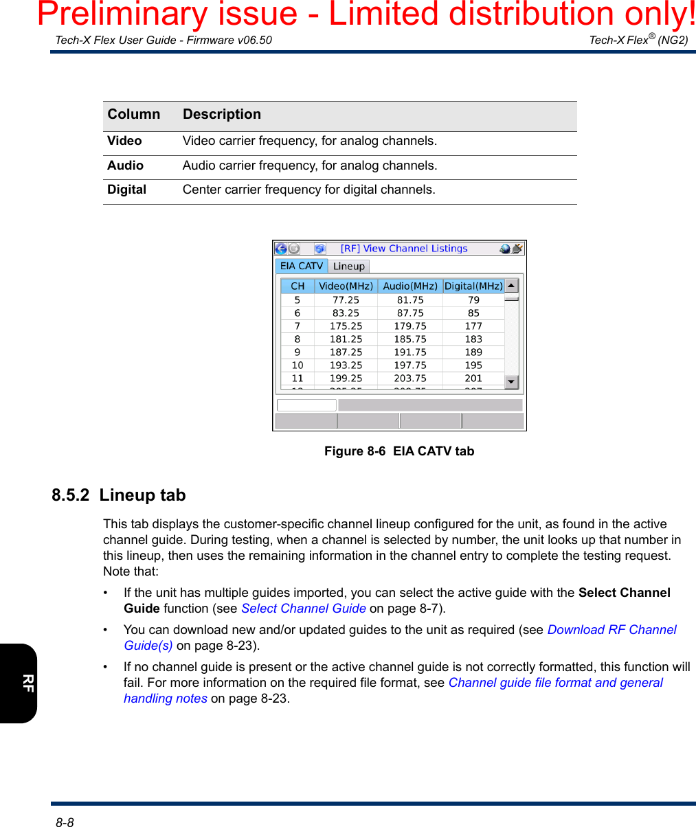
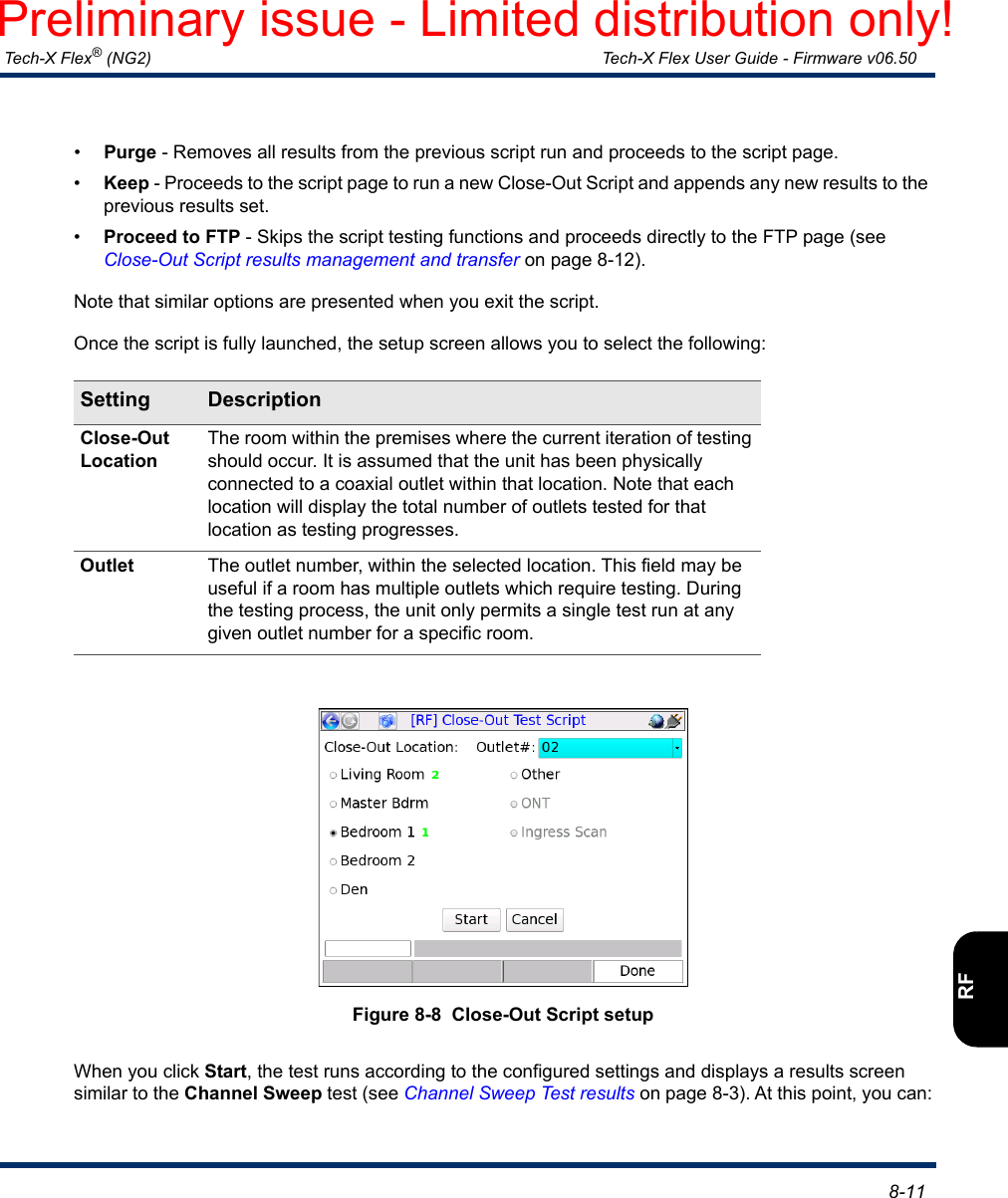
![Tech-X Flex® (NG2) Tech-X Flex User Guide - Firmware v06.50 8-7IntroOverviewWi-FiEthernetSystemIP/VideoMoCARFSpecs8.4 Select Channel GuideThis function allows you to select the active channel guide, if multiple guides are present on the unit. The unit uses the channel guide to verify valid frequencies and to correlate frequencies with channel numbers, in various areas of testing.Note that:• Only one guide may be active at any given time.• You can view the channel listings in the active guide at any time with the View Channel Listings function (see View Channel Listings on page 8-7).• You can download new and/or updated guides to the unit as required (see Download RF Channel Guide(s) on page 8-23).8.5 View Channel ListingsFrom the main RF menu, View Channel Listings allows you to view two channel tables on the unit:• The standard listing of TV channels and their associated frequencies (see EIA CATV tab on page 8-7)• The channel guide currently active on the unit, which should reflect the architecture under test (see Lineup tab on page 8-8)8.5.1 EIA CATV tabThis tab displays a list of channel numbers/designations and their associated frequencies supported by the module tuner, according to EIA standards[4]. Channels in the active channel guide (see Lineup tab on page 8-8) should each reference a channel from this list, which is how the unit determines the frequency(ies) for testing. The information in this tab is fixed according to the firmware package on the unit and cannot be changed by end users. For a listing of these channels, see Supported channels and frequencies on page 8-27.Column DescriptionCH Channel number or designation. Note the following:• This is not the number displayed in test setup and results screens. Rather, it is the number that should be referenced by a channel in the active channel guide (Lineup tab on page 8-8), as applicable.• Out-of-band (OOB) channels, if present, typically appear with an OOB designation rather than a number.Preliminary issue - Limited distribution only!](https://usermanual.wiki/Spirent-Communications/FLEX-T5300.User-Manual-Part-2/User-Guide-3054221-Page-104.png)
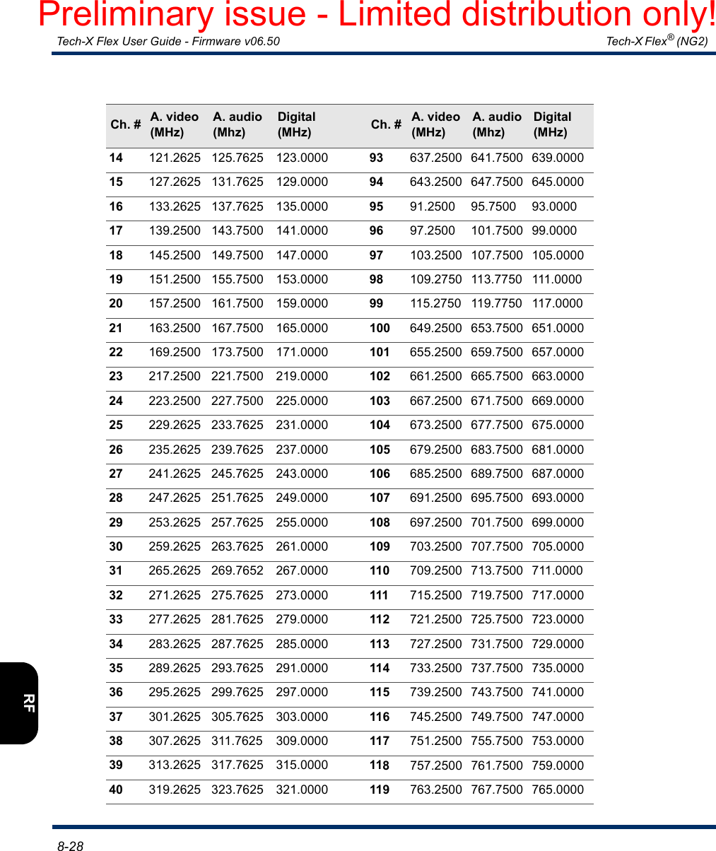
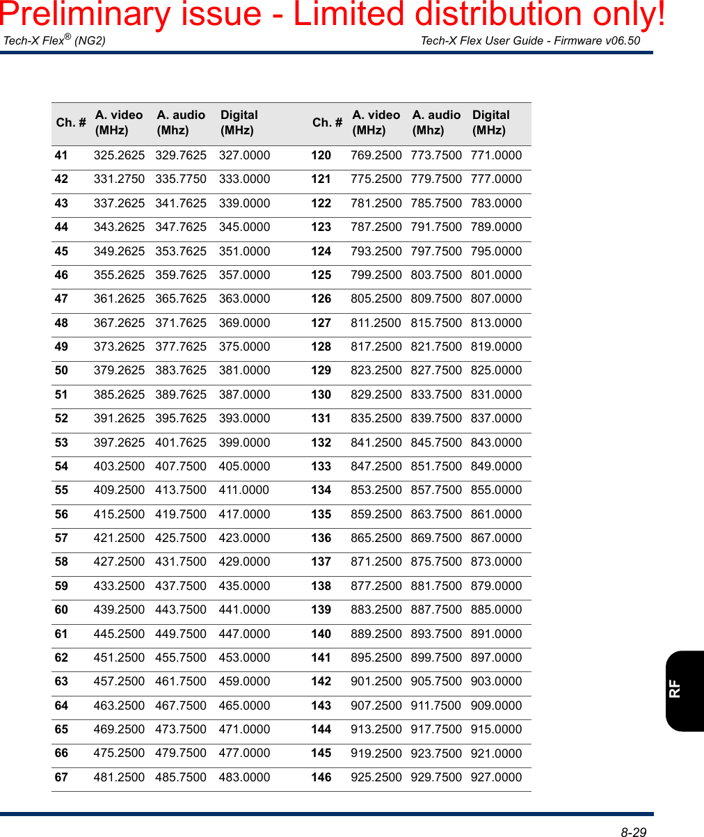
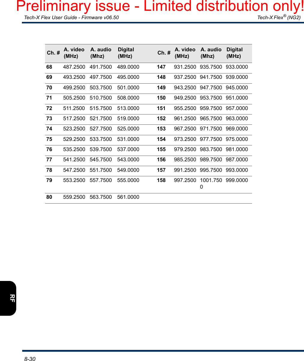
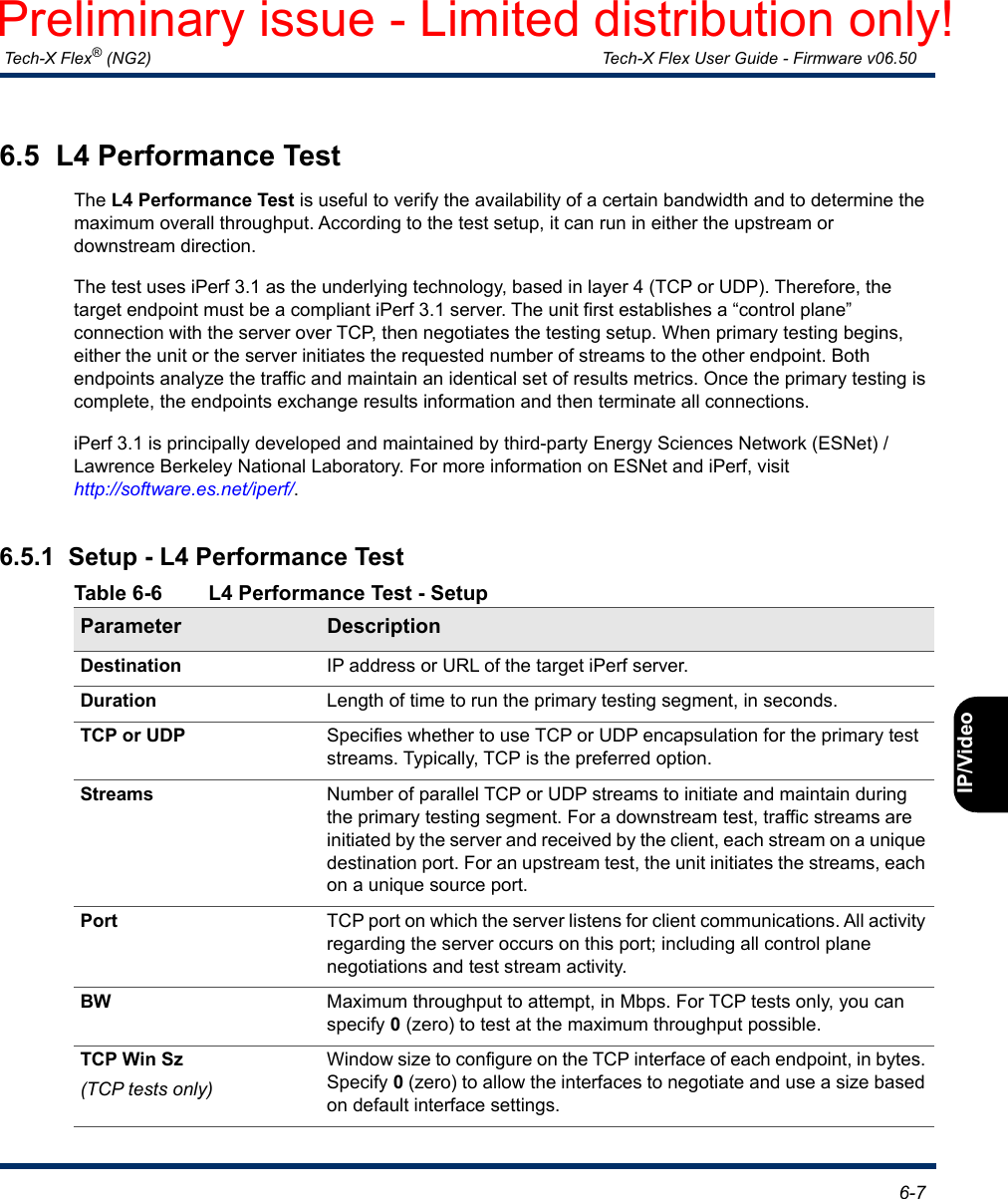
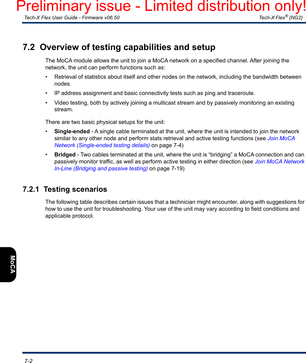
![Tech-X Flex® (NG2) Tech-X Flex User Guide - Firmware v06.50 8-27IntroOverviewWi-FiEthernetSystemIP/VideoMoCARFSpecsTable 8-3 FTP tab8.9 Supported channels and frequenciesThe module tuner supports the following EIA cable TV channels. Note that OOB channels are not listed:Setting DescriptionSystem NameA name under which all other FTP settings will be stored when you select Save. This feature is a convenience that allows you to store the profiles of multiple target servers and retrieve them later by selecting the name. To create a new profile, select [Create New] from the list and follow the prompts.Server IPPortUser IDPswdPing Before TransferInformation about the FTP server on the target computer, to which results are transferred following a script run. For more information, see FTP connection parameters on page 2-59.Ch. # A. video (MHz)A. audio (Mhz)Digital (MHz) Ch. # A. video (MHz)A. audio (Mhz)Digital (MHz)255.2500 59.7500 57.0000 81 565.2500 569.7500 567.0000361.2500 65.7500 63.0000 82 571.2500 575.7500 573.0000467.2500 71.7500 69.0000 83 577.2500 581.7500 579.0000577.2500 81.7500 79.0000 84 583.2500 587.7500 585.0000683.2500 87.7500 85.0000 85 589.2500 593.7500 591.00007175.2500 179.7500 177.0000 86 595.2500 599.7500 597.00008181.2500 185.7500 183.0000 87 601.2500 605.7500 603.00009187.2500 191.7500 189.0000 88 607.2500 611.7500 609.000010 193.2500 197.7500 195.0000 89 613.2500 617.7500 615.000011 199.2500 203.7500 201.0000 90 619.2500 623.7500 621.000012 205.2500 209.7500 207.0000 91 625.2500 629.7500 627.000013 211.2500 215.7500 213.0000 92 631.2500 635.7500 633.0000Preliminary issue - Limited distribution only!](https://usermanual.wiki/Spirent-Communications/FLEX-T5300.User-Manual-Part-2/User-Guide-3054221-Page-124.png)