Spirent Communications TXFLEX-NG2 Portable Communications Tester User Manual Tech X Flex Manual
Spirent Communications Inc Portable Communications Tester Tech X Flex Manual
UserManual.wiki
>
Spirent Communications
>
TXFLEX NG2 User Manual
Manual
Navigation menu
Upload a User Manual
Namespaces
Wiki Guide
HTML
PDF
Info
Views
User Manual
Discussion / Help
Navigation
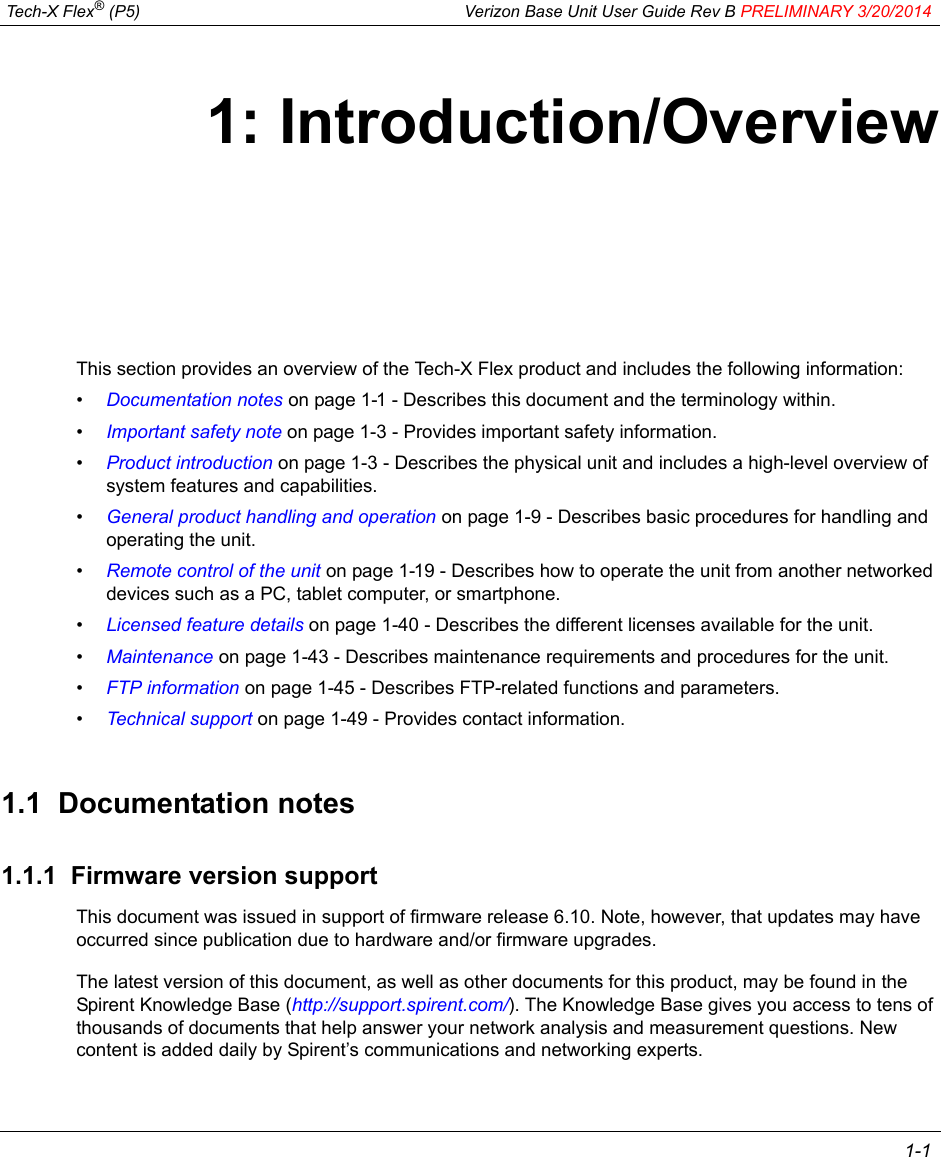
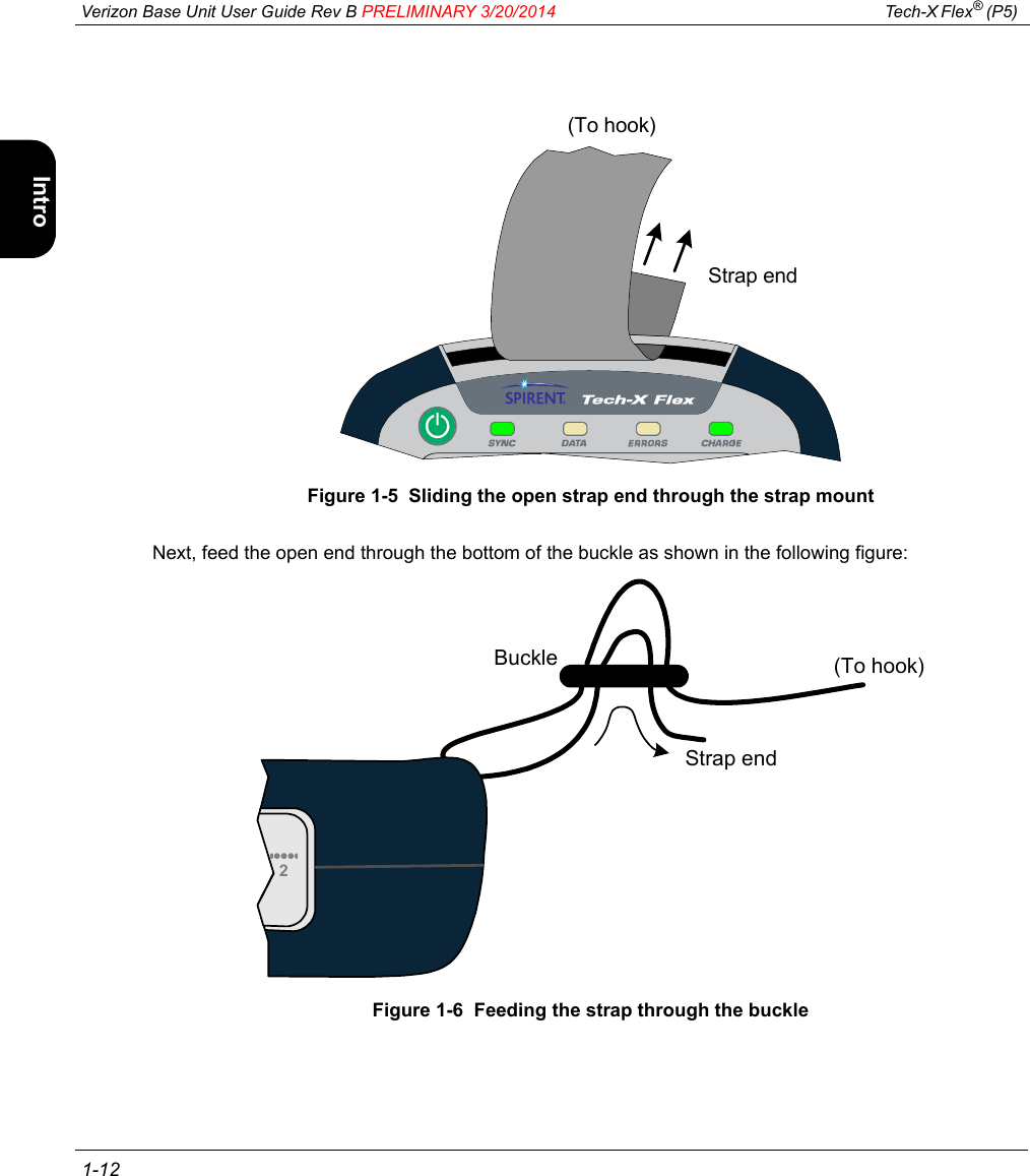
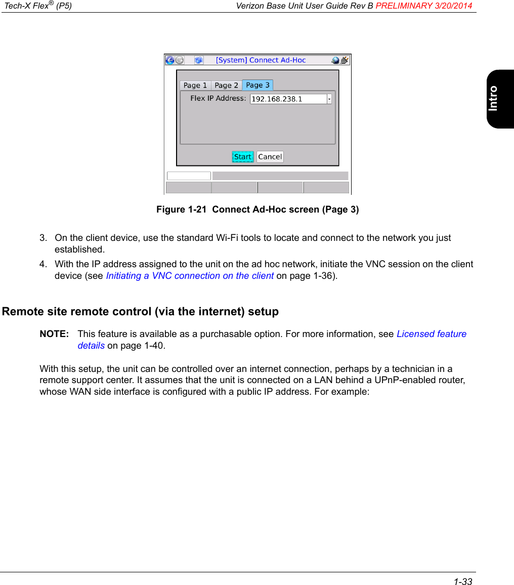
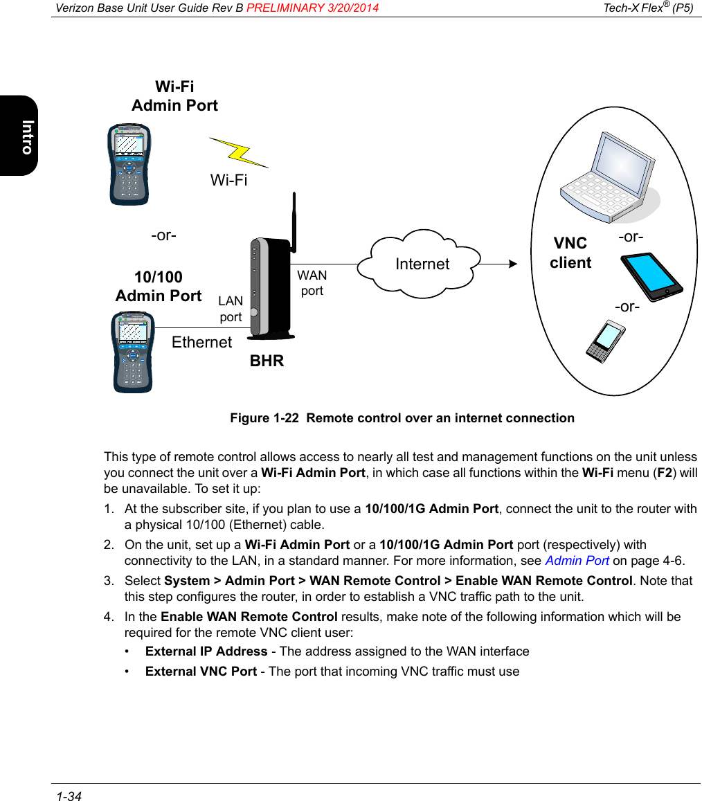
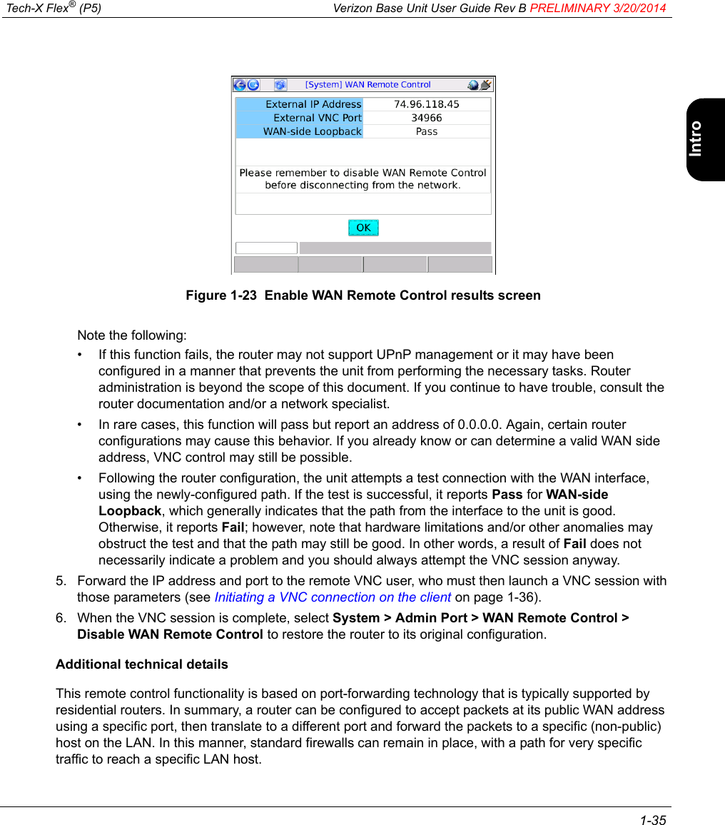
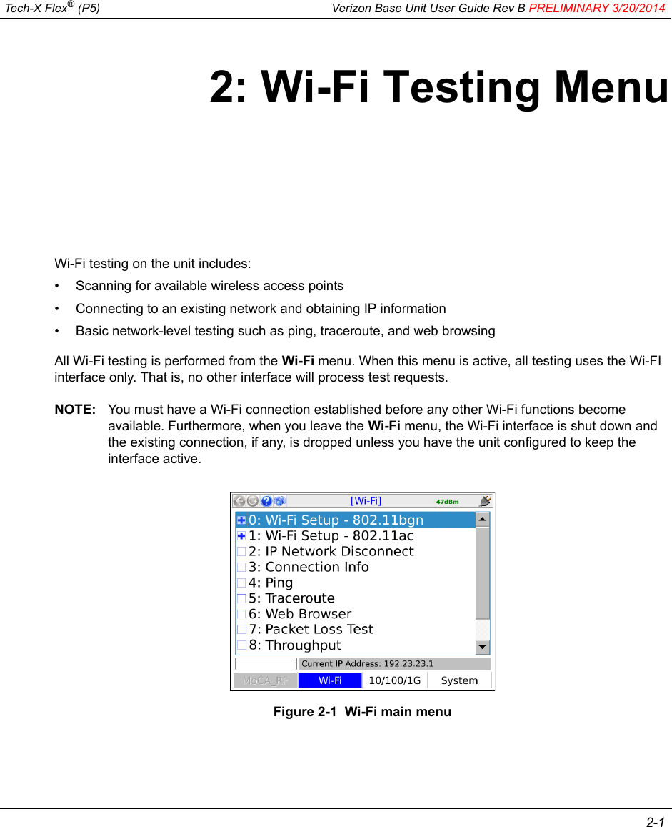
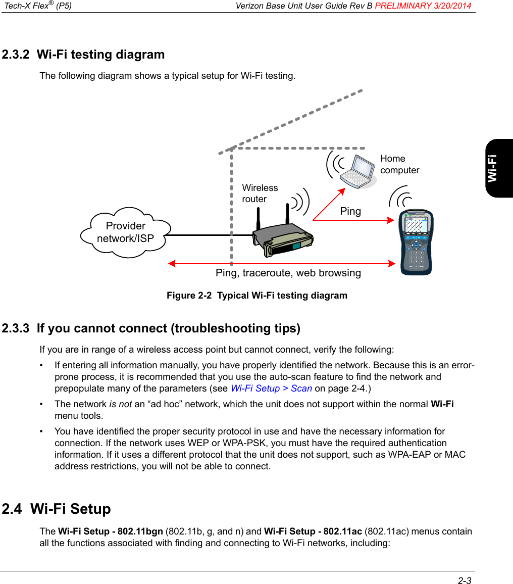
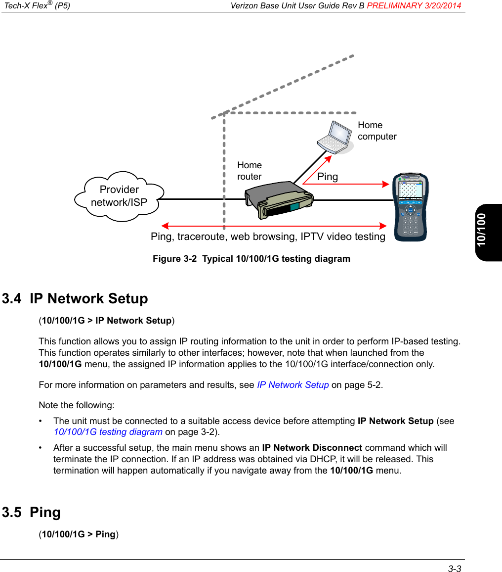
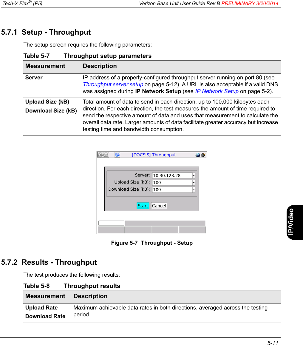
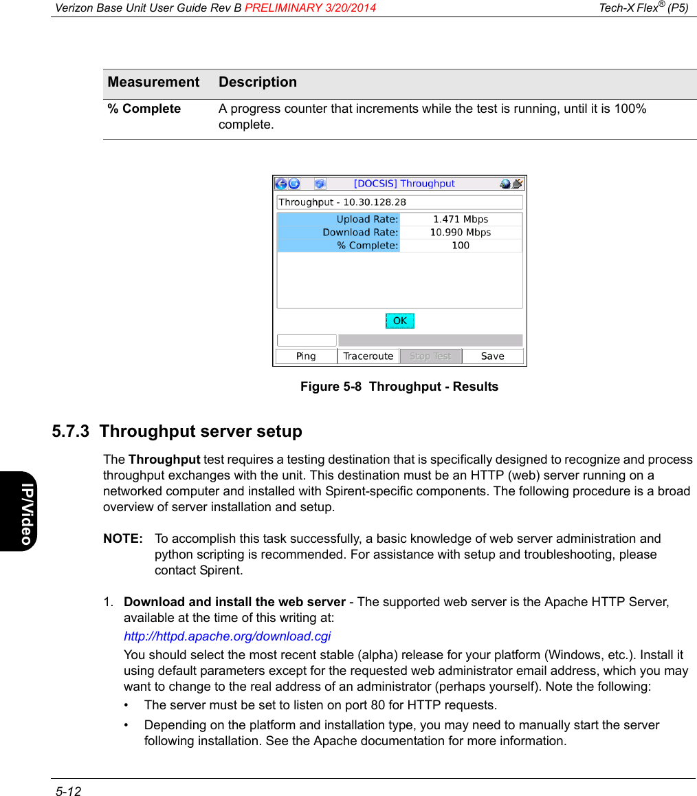
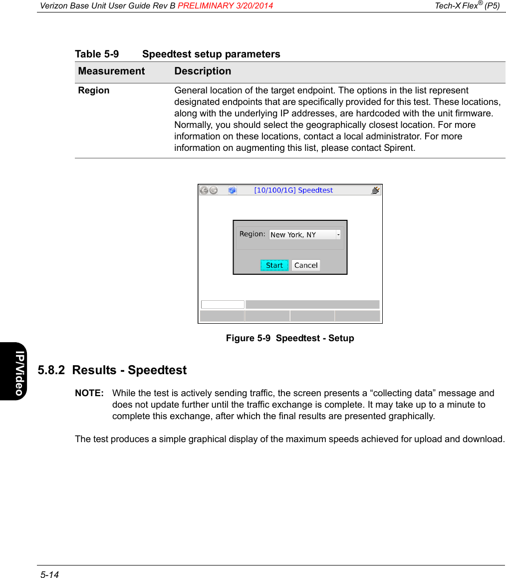
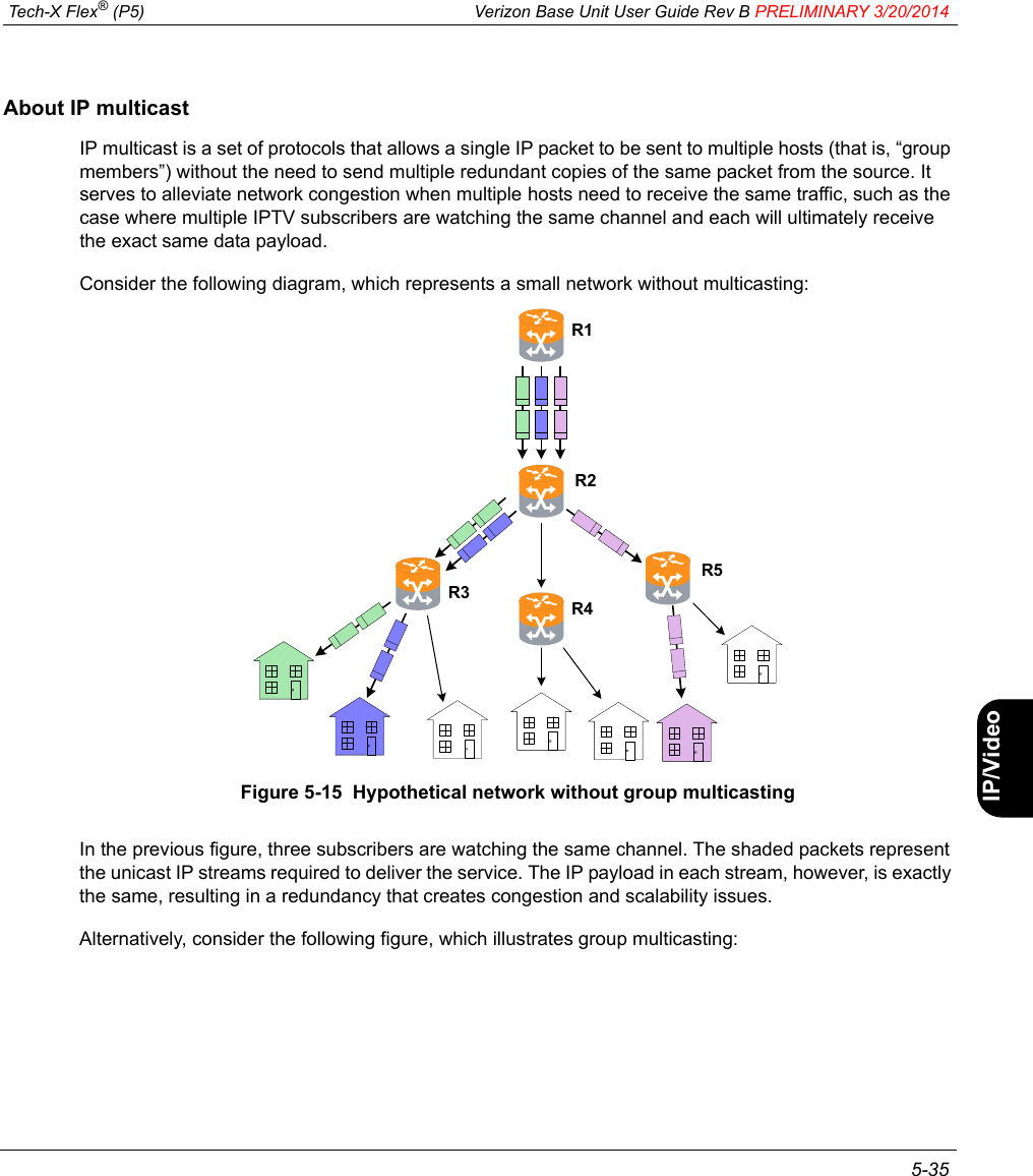
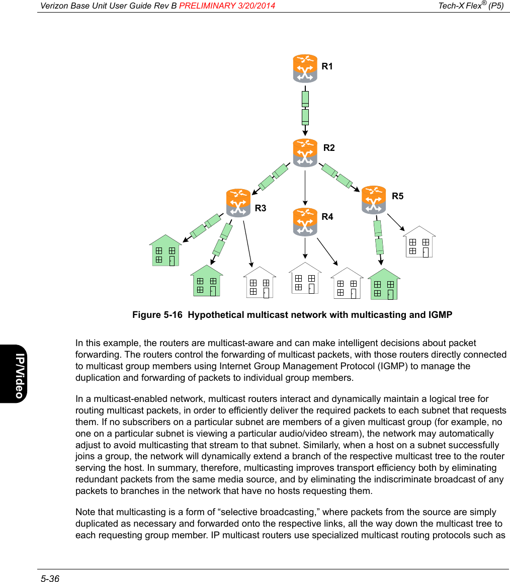
![Tech-X Flex® (P5) Verizon Base Unit User Guide Rev B PRELIMINARY 3/20/2014 1-5IntroWi-Fi10/100SystemIP/VideoSpecs1.3.4 Front panel controlsFigure 1-1 Front panel controls6: Web Browser2: IP Network Setup3: Connection Info4: Ping5: Traceroute0: Wi-Fi Setup – 802.11bgnMoCA-RF Wi-Fi 10/100/1G System[Wi-Fi]7: Packet Loss Test8: Throughput1: Wi-Fi Setup – 802.11acTouchscreen displayPower on/off LED indicatorsFunction keysAlphanumeric keypad (physical)EnterExitBrightnessHelpN1Strap mountArrow keys](https://usermanual.wiki/Spirent-Communications/TXFLEX-NG2/User-Guide-2223559-Page-15.png)