Spirent Communications TXFLEX-NG2 Portable Communications Tester User Manual Tech X Flex Manual
Spirent Communications Inc Portable Communications Tester Tech X Flex Manual
Manual
Tech-X Flex® (P5)
Base Unit User Guide
IMPORTANT NOTE: This is
a preliminary, draft
document for lab use only.
It is not intended for general
distribution.
March 20, 2014
Supports firmware version 06.10
REVISION A PRELIMINARY
Spirent Communications, Inc.
20324 Seneca Meadows Parkway
Germantown, MD 20876
USA
1-800-SPIRENT (North America)
Copyright
© 2013 Spirent Communications, Inc. All Rights Reserved.
All of the company names and/or brand names and/or product names referred to in this document, in particular, the name “Spirent” and its logo device,
are either registered trademarks or trademarks of Spirent plc and its subsidiaries, pending registration in accordance with relevant national laws. All
other registered trademarks or trademarks are the property of their respective owners. The information contained in this document is subject to change
without notice and does not represent a commitment on the part of Spirent Communications. The information in this document is believed to be
accurate and reliable, however, Spirent Communications assumes no responsibility or liability for any errors or inaccuracies that may appear in the
document.
Limited Warranty - Hardware
“Hardware Warranty Period” shall refer to the period beginning upon the applicable Delivery Date of any Spirent Hardware purchased under this
Agreement and ending one (1) year thereafter; except (a) the Hardware Warranty Period for rechargeable batteries shall be ninety (90) days following
the applicable Delivery Date. Subject to the provisions hereof, Spirent warrants the Spirent Hardware during the Hardware Warranty Period against
material defects in material and workmanship and against failure to perform in substantial accordance with the published specifications therefore in the
Documentation (any such failure or defect, a “Hardware Defect”).
Sole Remedies. During the Hardware Warranty Period, as Customer’s sole remedy with respect to any and all Hardware Defects, Spirent will repair or
replace as provided any Spirent Hardware that proves to have a Hardware Defect. To obtain a warranty repair, Spirent Hardware allegedly containing
Hardware Defects must be returned for repair or replacement in accordance with Spirent’s return procedure. Spirent Hardware corrected or replaced
will also be warranted for the remainder of the original Hardware Warranty Period or sixty (60) days, whichever is the longer.. If Spirent elects not to
repair a Hardware Defect and not to replace the item of Spirent Hardware containing the Hardware Defect with respect to an item of Spirent Hardware
under warranty, Spirent will at its sole expense refund to Customer the purchase price of such Spirent Hardware
Reporting Period. The limited warranty set forth is subject to the restrictions set forth below and is contingent upon Customer notifying Spirent in
writing within ten (10) days following Customer’s discovery of any alleged Hardware Defect, and in no event later than ten (10) days after the end of
the Hardware Warranty Period.
Exclusions. The limited warranty set forth herein will not apply with respect to Hardware Defects caused by (a) neglect, accident, fire or other hazard,
damage or scratches to the screen, unauthorized alteration, modification, or repair, including without limitation, installation of unauthorized parts, (b)
improper testing, storage, operation, interconnection, or installation of the Spirent Hardware, (c) damage to the Spirent Hardware after the Delivery
Date, (d) damage to the Spirent Hardware or defects in the Spirent Hardware that was or should have been obvious to Customer upon a visual and
physical inspection thereof within the five-day period after the applicable Delivery Date, unless Customer has notified Spirent thereof during such
five-day period as provided in these Terms and Conditions, or (e) any other cause beyond the range of normal usage of the Spirent Hardware (except,
in all of the foregoing cases, when caused by Spirent or Spirent’s authorized agent). This limited warranty shall terminate upon any transfer or sale of
the Spirent Hardware by Customer. Spirent reserves the right to make changes in the design or construction of any of the Spirent Hardware at any time
without incurring any obligations to make any changes whatever on Spirent Hardware items previously purchased, unless Customer has subscribed for
a Service that requires the same.
Limited Warranty - Software
For a period of 1 year after the applicable Delivery Date, Spirent warrants that the Spirent Software shall perform in all material respects in accordance
with the applicable specifications therefore set forth in the Documentation. The foregoing limited warranty shall not apply to any Software
Malfunction which results from: (a) modification or installation of the Spirent Software by anyone other than Spirent or Spirent’s authorized agent, (b)
use of the Spirent Software for any purpose other than the intended use as reflected in the accompanying Documentation, (c) use of the Spirent
Software in combination with any other software or hardware not approved or expressly contemplated for use with such Spirent Software in the
Documentation if such claim would have been avoided but for such combination, (d) any misuse or incorrect use of the Spirent Software, or (e) any
malfunction in hardware that is not Spirent Hardware. Subject to the foregoing limitations, with respect to Spirent Software containing a Software
Malfunction, provided (A) Customer has notified Spirent in writing of the nature of the Software Malfunction during the applicable warranty period
and within ten (10) days after Customer’s discovery of the Software Malfunction, and (B) Spirent is able to verify such Software Malfunction, Spirent
will, at its expense, (i) correct such Spirent Software’s failure to conform to the warranty, (ii) replace such Spirent Software with Software meeting
Spirent’s then-current published specifications or (iii) terminate the licensed rights granted herein with respect to the applicable Spirent Software and
grant Customer a refund of the applicable license fee, less reasonable depreciation based on usage, which shall in no event be less than the result of a
straight-line computation based upon a three (3) year usable life..
Tech-X Flex® (P5)
Verizon Base Unit User
Guide


Tech-X Flex® (P5) Verizon Base Unit User Guide Rev B PRELIMINARY 3/20/2014
-i
Contents
1: Introduction/Overview
1.1 Documentation notes . . . . . . . . . . . . . . . . . . . . . . . . . . . . . . . . . . . . . . . . . . . 1-1
1.1.1 Firmware version support . . . . . . . . . . . . . . . . . . . . . . . . . . . . . . . . . . . . . . . . . . . . . 1-1
1.1.2 Document purpose and scope . . . . . . . . . . . . . . . . . . . . . . . . . . . . . . . . . . . . . . . . . . 1-2
1.1.3 Definitions of terms and acronyms . . . . . . . . . . . . . . . . . . . . . . . . . . . . . . . . . . . . . . 1-2
1.1.4 Additional documentation . . . . . . . . . . . . . . . . . . . . . . . . . . . . . . . . . . . . . . . . . . . . . 1-3
1.2 Important safety note . . . . . . . . . . . . . . . . . . . . . . . . . . . . . . . . . . . . . . . . . . . 1-3
1.3 Product introduction . . . . . . . . . . . . . . . . . . . . . . . . . . . . . . . . . . . . . . . . . . . 1-3
1.3.1 Product purpose . . . . . . . . . . . . . . . . . . . . . . . . . . . . . . . . . . . . . . . . . . . . . . . . . . . . 1-3
1.3.2 User prerequisites . . . . . . . . . . . . . . . . . . . . . . . . . . . . . . . . . . . . . . . . . . . . . . . . . . . 1-3
1.3.3 Base unit features . . . . . . . . . . . . . . . . . . . . . . . . . . . . . . . . . . . . . . . . . . . . . . . . . . .1-4
1.3.4 Front panel controls . . . . . . . . . . . . . . . . . . . . . . . . . . . . . . . . . . . . . . . . . . . . . . . . . . 1-5
1.3.5 LED indicators . . . . . . . . . . . . . . . . . . . . . . . . . . . . . . . . . . . . . . . . . . . . . . . . . . . . . .1-6
1.3.6 Base unit physical interfaces (ports) . . . . . . . . . . . . . . . . . . . . . . . . . . . . . . . . . . . . . 1-8
1.3.7 Unit symbols . . . . . . . . . . . . . . . . . . . . . . . . . . . . . . . . . . . . . . . . . . . . . . . . . . . . . . .1-9
1.4 General product handling and operation . . . . . . . . . . . . . . . . . . . . . . . . . . . 1-9
1.4.1 Protection from water and dust ingress . . . . . . . . . . . . . . . . . . . . . . . . . . . . . . . . . . 1-10
1.4.2 Powering on/off and sleep mode . . . . . . . . . . . . . . . . . . . . . . . . . . . . . . . . . . . . . . . 1-10
1.4.3 Attaching, detaching, and handling modules . . . . . . . . . . . . . . . . . . . . . . . . . . . . . . 1-10
1.4.4 Attaching the strap . . . . . . . . . . . . . . . . . . . . . . . . . . . . . . . . . . . . . . . . . . . . . . . . . . 1-11
1.4.5 About the touchscreen display . . . . . . . . . . . . . . . . . . . . . . . . . . . . . . . . . . . . . . . . 1-13
1.4.6 Selecting the active interface . . . . . . . . . . . . . . . . . . . . . . . . . . . . . . . . . . . . . . . . . . 1-13
1.4.7 Running a function or test . . . . . . . . . . . . . . . . . . . . . . . . . . . . . . . . . . . . . . . . . . . . 1-13
1.4.8 Repeating a function or test . . . . . . . . . . . . . . . . . . . . . . . . . . . . . . . . . . . . . . . . . . . 1-15
1.4.9 Screen title bar buttons/icons . . . . . . . . . . . . . . . . . . . . . . . . . . . . . . . . . . . . . . . . . 1-15

Verizon Base Unit User Guide Rev B PRELIMINARY 3/20/2014 Tech-X Flex® (P5)
-ii
Intro Wi-Fi 10/100 System IP/Video Specs
1.4.10 Capturing a screen image (screenshot) . . . . . . . . . . . . . . . . . . . . . . . . . . . . . . . . .1-17
1.4.11 Stopping a test . . . . . . . . . . . . . . . . . . . . . . . . . . . . . . . . . . . . . . . . . . . . . . . . . . . .1-18
1.4.12 Saving results . . . . . . . . . . . . . . . . . . . . . . . . . . . . . . . . . . . . . . . . . . . . . . . . . . . .1-18
1.4.13 Maximum test duration for continuous tests . . . . . . . . . . . . . . . . . . . . . . . . . . . . .1-18
1.4.14 Interpreting results . . . . . . . . . . . . . . . . . . . . . . . . . . . . . . . . . . . . . . . . . . . . . . . . .1-18
1.4.15 Important MoCA module compatibility note . . . . . . . . . . . . . . . . . . . . . . . . . . . . . .1-19
1.5 Remote control of the unit . . . . . . . . . . . . . . . . . . . . . . . . . . . . . . . . . . . . . . 1-19
1.5.1 About VNC . . . . . . . . . . . . . . . . . . . . . . . . . . . . . . . . . . . . . . . . . . . . . . . . . . . . . . . .1-19
1.5.2 Installing a VNC client (viewer) . . . . . . . . . . . . . . . . . . . . . . . . . . . . . . . . . . . . . . . .1-20
RealVNC 4.1.3 installation and setup . . . . . . . . . . . . . . . . . . . . . . . . . . . . . . . . . . . . . .1-20
RealVNC 5.0.5 installation and setup . . . . . . . . . . . . . . . . . . . . . . . . . . . . . . . . . . . . . .1-21
1.5.3 Remote control setup scenarios . . . . . . . . . . . . . . . . . . . . . . . . . . . . . . . . . . . . . . .1-29
Local remote control (via a router/LAN) setup . . . . . . . . . . . . . . . . . . . . . . . . . . . . . . .1-30
Local remote control (via ad hoc Wi-Fi) setup . . . . . . . . . . . . . . . . . . . . . . . . . . . . . . .1-31
Remote site remote control (via the internet) setup . . . . . . . . . . . . . . . . . . . . . . . . . . .1-33
1.5.4 Initiating a VNC connection on the client . . . . . . . . . . . . . . . . . . . . . . . . . . . . . . . . .1-36
1.6 Licensed feature details . . . . . . . . . . . . . . . . . . . . . . . . . . . . . . . . . . . . . . . . 1-40
1.7 Maintenance . . . . . . . . . . . . . . . . . . . . . . . . . . . . . . . . . . . . . . . . . . . . . . . . . . 1-43
1.7.1 Battery installation/replacement . . . . . . . . . . . . . . . . . . . . . . . . . . . . . . . . . . . . . . . .1-44
1.8 FTP information . . . . . . . . . . . . . . . . . . . . . . . . . . . . . . . . . . . . . . . . . . . . . . . 1-45
1.8.1 Admin Port setup . . . . . . . . . . . . . . . . . . . . . . . . . . . . . . . . . . . . . . . . . . . . . . . . . .1-45
1.8.2 FTP server installation and setup . . . . . . . . . . . . . . . . . . . . . . . . . . . . . . . . . . . . . .1-46
1.8.3 FTP connection parameters . . . . . . . . . . . . . . . . . . . . . . . . . . . . . . . . . . . . . . . . . . .1-47
1.8.4 FTP connection troubleshooting . . . . . . . . . . . . . . . . . . . . . . . . . . . . . . . . . . . . . . .1-49
1.9 Technical support . . . . . . . . . . . . . . . . . . . . . . . . . . . . . . . . . . . . . . . . . . . . . 1-49
2: Wi-Fi Testing Menu
2.1 Important wireless 802.11ac note . . . . . . . . . . . . . . . . . . . . . . . . . . . . . . . . . 2-2
2.2 Functionality note . . . . . . . . . . . . . . . . . . . . . . . . . . . . . . . . . . . . . . . . . . . . . . 2-2
2.3 Wi-Fi overview . . . . . . . . . . . . . . . . . . . . . . . . . . . . . . . . . . . . . . . . . . . . . . . . . 2-2
2.3.1 Wi-Fi support details . . . . . . . . . . . . . . . . . . . . . . . . . . . . . . . . . . . . . . . . . . . . . . . . .2-2
2.3.2 Wi-Fi testing diagram . . . . . . . . . . . . . . . . . . . . . . . . . . . . . . . . . . . . . . . . . . . . . . . . .2-3
2.3.3 If you cannot connect (troubleshooting tips) . . . . . . . . . . . . . . . . . . . . . . . . . . . . . . .2-3
2.4 Wi-Fi Setup . . . . . . . . . . . . . . . . . . . . . . . . . . . . . . . . . . . . . . . . . . . . . . . . . . . . 2-3

Tech-X Flex® (P5) Verizon Base Unit User Guide Rev B PRELIMINARY 3/20/2014
-iii
Intro
Wi-Fi
10/100
System
IP/Video
Specs
2.4.1 Wi-Fi Setup > Scan . . . . . . . . . . . . . . . . . . . . . . . . . . . . . . . . . . . . . . . . . . . . . . . . . 2-4
Setup - Scan (Wi-Fi Setup) . . . . . . . . . . . . . . . . . . . . . . . . . . . . . . . . . . . . . . . . . . . . . . 2-4
Results - Scan (Wi-Fi Setup) . . . . . . . . . . . . . . . . . . . . . . . . . . . . . . . . . . . . . . . . . . . . 2-4
2.4.2 Wi-Fi Setup > Connect . . . . . . . . . . . . . . . . . . . . . . . . . . . . . . . . . . . . . . . . . . . . . . 2-5
Setup - Connect (Wi-Fi Setup) . . . . . . . . . . . . . . . . . . . . . . . . . . . . . . . . . . . . . . . . . . . 2-6
Results - Connect (Wi-Fi Setup) . . . . . . . . . . . . . . . . . . . . . . . . . . . . . . . . . . . . . . . . . . 2-8
2.4.3 Wi-Fi Setup > Wi-Fi Quick Test . . . . . . . . . . . . . . . . . . . . . . . . . . . . . . . . . . . . . . . . 2-8
2.4.4 Wi-Fi Setup > Details . . . . . . . . . . . . . . . . . . . . . . . . . . . . . . . . . . . . . . . . . . . . . . . 2-10
2.5 IP Network Setup . . . . . . . . . . . . . . . . . . . . . . . . . . . . . . . . . . . . . . . . . . . . . 2-11
2.6 Ping . . . . . . . . . . . . . . . . . . . . . . . . . . . . . . . . . . . . . . . . . . . . . . . . . . . . . . . . 2-11
2.7 Traceroute . . . . . . . . . . . . . . . . . . . . . . . . . . . . . . . . . . . . . . . . . . . . . . . . . . . 2-11
2.8 Web Browser . . . . . . . . . . . . . . . . . . . . . . . . . . . . . . . . . . . . . . . . . . . . . . . . . 2-11
2.9 Packet Loss Test. . . . . . . . . . . . . . . . . . . . . . . . . . . . . . . . . . . . . . . . . . . . . . 2-11
2.10 Throughput . . . . . . . . . . . . . . . . . . . . . . . . . . . . . . . . . . . . . . . . . . . . . . . . . 2-12
2.11 Speedtest. . . . . . . . . . . . . . . . . . . . . . . . . . . . . . . . . . . . . . . . . . . . . . . . . . . 2-12
3: 10/100/1G Testing Menu
3.1 Functionality note . . . . . . . . . . . . . . . . . . . . . . . . . . . . . . . . . . . . . . . . . . . . . . 3-2
3.2 About the 10/100/1G ports and connections . . . . . . . . . . . . . . . . . . . . . . . . 3-2
3.3 10/100/1G testing diagram . . . . . . . . . . . . . . . . . . . . . . . . . . . . . . . . . . . . . . . 3-2
3.4 IP Network Setup . . . . . . . . . . . . . . . . . . . . . . . . . . . . . . . . . . . . . . . . . . . . . . 3-3
3.5 Ping . . . . . . . . . . . . . . . . . . . . . . . . . . . . . . . . . . . . . . . . . . . . . . . . . . . . . . . . . 3-3
3.6 Traceroute . . . . . . . . . . . . . . . . . . . . . . . . . . . . . . . . . . . . . . . . . . . . . . . . . . . . 3-4
3.7 Web Browser . . . . . . . . . . . . . . . . . . . . . . . . . . . . . . . . . . . . . . . . . . . . . . . . . . 3-4
3.8 Packet Loss Test. . . . . . . . . . . . . . . . . . . . . . . . . . . . . . . . . . . . . . . . . . . . . . . 3-4
3.9 Throughput . . . . . . . . . . . . . . . . . . . . . . . . . . . . . . . . . . . . . . . . . . . . . . . . . . . 3-4
3.10 Speedtest. . . . . . . . . . . . . . . . . . . . . . . . . . . . . . . . . . . . . . . . . . . . . . . . . . . . 3-5
3.11 IP Video Tests . . . . . . . . . . . . . . . . . . . . . . . . . . . . . . . . . . . . . . . . . . . . . . . . 3-5
3.12 Passive testing . . . . . . . . . . . . . . . . . . . . . . . . . . . . . . . . . . . . . . . . . . . . . . . 3-5
3.12.1 Unit setup for passive testing . . . . . . . . . . . . . . . . . . . . . . . . . . . . . . . . . . . . . . . . . 3-5
3.12.2 Passive Video QoS (Quality of Service) . . . . . . . . . . . . . . . . . . . . . . . . . . . . . . . . . 3-6

Verizon Base Unit User Guide Rev B PRELIMINARY 3/20/2014 Tech-X Flex® (P5)
-iv
Intro Wi-Fi 10/100 System IP/Video Specs
4: System Menu
4.1 Record Manager. . . . . . . . . . . . . . . . . . . . . . . . . . . . . . . . . . . . . . . . . . . . . . . . 4-1
4.1.1 About automatic result file upload . . . . . . . . . . . . . . . . . . . . . . . . . . . . . . . . . . . . . . .4-2
4.1.2 Record Manager > Test Result Files . . . . . . . . . . . . . . . . . . . . . . . . . . . . . . . . . . .4-3
4.1.3 Record Manager > Signature Cap Files . . . . . . . . . . . . . . . . . . . . . . . . . . . . . . . . .4-5
4.1.4 Record Manager > Screen Capture Files . . . . . . . . . . . . . . . . . . . . . . . . . . . . . . . .4-5
4.1.5 Record Manager > Upload Files . . . . . . . . . . . . . . . . . . . . . . . . . . . . . . . . . . . . . . .4-5
4.1.6 Record Manager > Inventory Upload Verizon . . . . . . . . . . . . . . . . . . . . . . . . . . . .4-5
4.1.7 Record Manager > Download System Settings . . . . . . . . . . . . . . . . . . . . . . . . . . .4-6
4.2 Admin Port . . . . . . . . . . . . . . . . . . . . . . . . . . . . . . . . . . . . . . . . . . . . . . . . . . . . 4-6
4.3 Set Date and Time . . . . . . . . . . . . . . . . . . . . . . . . . . . . . . . . . . . . . . . . . . . . . . 4-8
4.4 Sync with PC . . . . . . . . . . . . . . . . . . . . . . . . . . . . . . . . . . . . . . . . . . . . . . . . . . 4-8
4.5 Version Info . . . . . . . . . . . . . . . . . . . . . . . . . . . . . . . . . . . . . . . . . . . . . . . . . . . 4-9
4.6 Battery Status . . . . . . . . . . . . . . . . . . . . . . . . . . . . . . . . . . . . . . . . . . . . . . . . . 4-9
4.7 Download IPTV Channel Guide . . . . . . . . . . . . . . . . . . . . . . . . . . . . . . . . . . . 4-9
4.7.1 File preparation and general handling notes . . . . . . . . . . . . . . . . . . . . . . . . . . . . . .4-10
4.7.2 Download procedure . . . . . . . . . . . . . . . . . . . . . . . . . . . . . . . . . . . . . . . . . . . . . . . .4-10
4.8 Cal Touchscreen . . . . . . . . . . . . . . . . . . . . . . . . . . . . . . . . . . . . . . . . . . . . . . 4-10
4.9 Licensed Options. . . . . . . . . . . . . . . . . . . . . . . . . . . . . . . . . . . . . . . . . . . . . . 4-11
4.10 Update Firmware . . . . . . . . . . . . . . . . . . . . . . . . . . . . . . . . . . . . . . . . . . . . . 4-11
4.11 System/Module Settings . . . . . . . . . . . . . . . . . . . . . . . . . . . . . . . . . . . . . . . 4-14
4.11.1 System/Module Settings > Base Unit . . . . . . . . . . . . . . . . . . . . . . . . . . . . . . . . .4-15
4.11.2 System/Module Settings > RF Video Module . . . . . . . . . . . . . . . . . . . . . . . . . .4-15
4.11.3 System/Module Settings > ADSL/VDSL2 Module . . . . . . . . . . . . . . . . . . . . . . .4-15
4.11.4 System/Module Settings > Combined Module Default . . . . . . . . . . . . . . . . . . .4-15
4.11.5 System/Module Settings > MoCA Module . . . . . . . . . . . . . . . . . . . . . . . . . . . . .4-15
4.11.6 System/Module Settings > DOCSIS Module . . . . . . . . . . . . . . . . . . . . . . . . . . .4-15
4.11.7 System/Module Settings > CSM Module . . . . . . . . . . . . . . . . . . . . . . . . . . . . . .4-16
4.11.8 System/Module Settings > MoCA-RF Module . . . . . . . . . . . . . . . . . . . . . . . . . .4-16
4.11.9 System/Module Settings > Wi-Fi . . . . . . . . . . . . . . . . . . . . . . . . . . . . . . . . . . . . .4-16
System/Module Settings > Wi-Fi > View/Edit Thresholds . . . . . . . . . . . . . . . . . . . .4-16
System/Module Settings > Wi-Fi > Download Thresholds . . . . . . . . . . . . . . . . . . .4-17
System/Module Settings > Wi-Fi > Quick Test Region . . . . . . . . . . . . . . . . . . . . . .4-18

Tech-X Flex® (P5) Verizon Base Unit User Guide Rev B PRELIMINARY 3/20/2014
-v
Intro
Wi-Fi
10/100
System
IP/Video
Specs
4.12 Taskforce . . . . . . . . . . . . . . . . . . . . . . . . . . . . . . . . . . . . . . . . . . . . . . . . . . . 4-18
4.13 Signature Capture. . . . . . . . . . . . . . . . . . . . . . . . . . . . . . . . . . . . . . . . . . . . 4-19
4.14 Language Selection . . . . . . . . . . . . . . . . . . . . . . . . . . . . . . . . . . . . . . . . . . 4-19
4.15 Help and Support . . . . . . . . . . . . . . . . . . . . . . . . . . . . . . . . . . . . . . . . . . . . 4-19
5: IP and Video Testing
5.1 IP Network Setup . . . . . . . . . . . . . . . . . . . . . . . . . . . . . . . . . . . . . . . . . . . . . . 5-2
5.1.1 Setup - IP Network Setup . . . . . . . . . . . . . . . . . . . . . . . . . . . . . . . . . . . . . . . . . . . . 5-2
5.1.2 Results - IP Network Setup . . . . . . . . . . . . . . . . . . . . . . . . . . . . . . . . . . . . . . . . . . . 5-3
5.2 Connection Info. . . . . . . . . . . . . . . . . . . . . . . . . . . . . . . . . . . . . . . . . . . . . . . . 5-4
5.3 Ping . . . . . . . . . . . . . . . . . . . . . . . . . . . . . . . . . . . . . . . . . . . . . . . . . . . . . . . . . 5-4
5.3.1 Setup - Ping . . . . . . . . . . . . . . . . . . . . . . . . . . . . . . . . . . . . . . . . . . . . . . . . . . . . . . . 5-5
5.3.2 Results - Ping . . . . . . . . . . . . . . . . . . . . . . . . . . . . . . . . . . . . . . . . . . . . . . . . . . . . . . 5-5
5.4 Traceroute . . . . . . . . . . . . . . . . . . . . . . . . . . . . . . . . . . . . . . . . . . . . . . . . . . . . 5-6
5.4.1 Setup - Traceroute test . . . . . . . . . . . . . . . . . . . . . . . . . . . . . . . . . . . . . . . . . . . . . . . 5-6
5.4.2 Results - Traceroute test . . . . . . . . . . . . . . . . . . . . . . . . . . . . . . . . . . . . . . . . . . . . . 5-6
5.5 Web Browser . . . . . . . . . . . . . . . . . . . . . . . . . . . . . . . . . . . . . . . . . . . . . . . . . . 5-7
5.5.1 Setup - Web Browser . . . . . . . . . . . . . . . . . . . . . . . . . . . . . . . . . . . . . . . . . . . . . . . . 5-7
5.6 Packet Loss Test. . . . . . . . . . . . . . . . . . . . . . . . . . . . . . . . . . . . . . . . . . . . . . . 5-8
5.6.1 Setup - Packet Loss Test . . . . . . . . . . . . . . . . . . . . . . . . . . . . . . . . . . . . . . . . . . . . . 5-8
5.6.2 Results - Packet Loss Test . . . . . . . . . . . . . . . . . . . . . . . . . . . . . . . . . . . . . . . . . . . 5-9
5.7 Throughput . . . . . . . . . . . . . . . . . . . . . . . . . . . . . . . . . . . . . . . . . . . . . . . . . . 5-10
5.7.1 Setup - Throughput . . . . . . . . . . . . . . . . . . . . . . . . . . . . . . . . . . . . . . . . . . . . . . . . 5-11
5.7.2 Results - Throughput . . . . . . . . . . . . . . . . . . . . . . . . . . . . . . . . . . . . . . . . . . . . . . . 5-11
5.7.3 Throughput server setup . . . . . . . . . . . . . . . . . . . . . . . . . . . . . . . . . . . . . . . . . . . . 5-12
5.8 Speedtest. . . . . . . . . . . . . . . . . . . . . . . . . . . . . . . . . . . . . . . . . . . . . . . . . . . . 5-13
5.8.1 Setup - Speedtest . . . . . . . . . . . . . . . . . . . . . . . . . . . . . . . . . . . . . . . . . . . . . . . . . . 5-13
5.8.2 Results - Speedtest . . . . . . . . . . . . . . . . . . . . . . . . . . . . . . . . . . . . . . . . . . . . . . . . 5-14
5.9 IP Video testing . . . . . . . . . . . . . . . . . . . . . . . . . . . . . . . . . . . . . . . . . . . . . . . 5-15
5.9.1 Video QoS (Quality of Service) . . . . . . . . . . . . . . . . . . . . . . . . . . . . . . . . . . . . . . . . 5-16
Setup - Video QoS . . . . . . . . . . . . . . . . . . . . . . . . . . . . . . . . . . . . . . . . . . . . . . . . . . . . 5-16
Results - Video QoS (MDI test) . . . . . . . . . . . . . . . . . . . . . . . . . . . . . . . . . . . . . . . . . . 5-23
Results - Video QoS (VQM test) . . . . . . . . . . . . . . . . . . . . . . . . . . . . . . . . . . . . . . . . . 5-24

Verizon Base Unit User Guide Rev B PRELIMINARY 3/20/2014 Tech-X Flex® (P5)
-vi
Intro Wi-Fi 10/100 System IP/Video Specs
Digital video concepts overview . . . . . . . . . . . . . . . . . . . . . . . . . . . . . . . . . . . . . . . . . .5-31
Video quality measurement (VQM) overview and additional results descriptions . . . .5-37
MDI measurement overview . . . . . . . . . . . . . . . . . . . . . . . . . . . . . . . . . . . . . . . . . . . . .5-40
Additional video testing notes . . . . . . . . . . . . . . . . . . . . . . . . . . . . . . . . . . . . . . . . . . . .5-42
5.9.2 Change Channel . . . . . . . . . . . . . . . . . . . . . . . . . . . . . . . . . . . . . . . . . . . . . . . . . . .5-43
Setup - Change Channel . . . . . . . . . . . . . . . . . . . . . . . . . . . . . . . . . . . . . . . . . . . . . . .5-43
Results - Change Channel . . . . . . . . . . . . . . . . . . . . . . . . . . . . . . . . . . . . . . . . . . . . .5-44
How channel change time is calculated . . . . . . . . . . . . . . . . . . . . . . . . . . . . . . . . . . . .5-44
5.9.3 Channel Guide Settings . . . . . . . . . . . . . . . . . . . . . . . . . . . . . . . . . . . . . . . . . . . .5-45
About channel guides . . . . . . . . . . . . . . . . . . . . . . . . . . . . . . . . . . . . . . . . . . . . . . . . . .5-45
Importing channel guides to the unit . . . . . . . . . . . . . . . . . . . . . . . . . . . . . . . . . . . . . . .5-47
6: Specifications
6.1 General specifications . . . . . . . . . . . . . . . . . . . . . . . . . . . . . . . . . . . . . . . . . . 6-1
6.2 Wi-Fi specifications . . . . . . . . . . . . . . . . . . . . . . . . . . . . . . . . . . . . . . . . . . . . . 6-2
6.3 FCC compliance statements. . . . . . . . . . . . . . . . . . . . . . . . . . . . . . . . . . . . . . 6-2

Tech-X Flex® (P5) Verizon Base Unit User Guide Rev B PRELIMINARY 3/20/2014
1-1
1: Introduction/Overview
This section provides an overview of the Tech-X Flex product and includes the following information:
•Documentation notes on page 1-1 - Describes this document and the terminology within.
•Important safety note on page 1-3 - Provides important safety information.
•Product introduction on page 1-3 - Describes the physical unit and includes a high-level overview of
system features and capabilities.
•General product handling and operation on page 1-9 - Describes basic procedures for handling and
operating the unit.
•Remote control of the unit on page 1-19 - Describes how to operate the unit from another networked
devices such as a PC, tablet computer, or smartphone.
•Licensed feature details on page 1-40 - Describes the different licenses available for the unit.
•Maintenance on page 1-43 - Describes maintenance requirements and procedures for the unit.
•FTP information on page 1-45 - Describes FTP-related functions and parameters.
•Technical support on page 1-49 - Provides contact information.
1.1 Documentation notes
1.1.1 Firmware version support
This document was issued in support of firmware release 6.10. Note, however, that updates may have
occurred since publication due to hardware and/or firmware upgrades.
The latest version of this document, as well as other documents for this product, may be found in the
Spirent Knowledge Base (http://support.spirent.com/). The Knowledge Base gives you access to tens of
thousands of documents that help answer your network analysis and measurement questions. New
content is added daily by Spirent’s communications and networking experts.

Verizon Base Unit User Guide Rev B PRELIMINARY 3/20/2014 Tech-X Flex® (P5)
1-2
Intro Wi-Fi 10/100 System IP/Video Specs
Sign in with your user ID and password to gain access to additional content that is available only to
customers – user manuals, help files, release notes, tech bulletins, and more. When you sign in, you can
also use the Knowledge Base to download software and firmware, and to manage your Service
Requests (SRs).
1.1.2 Document purpose and scope
This document is intended for field technicians and other personnel who use the product for circuit and
network testing. Depending upon your licensing agreement, your unit may not include all the
functionality presented in this document. For more information about licensing arrangements, please
contact a Spirent account manager.
1.1.3 Definitions of terms and acronyms
For clarity, the following terms are defined:
•Unit - A Tech-X Flex device in general, with or without a module attached, as applicable to the
respective context.
•Base Unit - The core handheld component to which modules attach. The base unit has an
independent suite of functionality which is described in this document. The use of modules does not
change base unit functionality.
•Module - A modular hardware component designed to attach and interface with the Tech-X Flex base
unit that provides additional functionality. Documentation for modules is provided separately from this
document.
•Provider - A broadband service provider, such as a telephone or cable company.
•Subscriber - A customer receiving broadband services from a provider.
Additionally, note the following common acronyms:
•FTTH/FTTP - Fiber To The Home/Fiber To The Premises
•IP - Internet Protocol
•IPTV - IP Television
•LAN - Local Area Network
•MoCA® - Multimedia over Coax Alliance
•BHR - Broadband Home Router
•STB - Set-Top Box
•WAN - Wide Area Network
•VNC - Virtual Network Computing

Tech-X Flex® (P5) Verizon Base Unit User Guide Rev B PRELIMINARY 3/20/2014
1-3
Intro
Wi-Fi
10/100
System
IP/Video
Specs
1.1.4 Additional documentation
Additional documentation (including an electronic version of this document) can be found on Spirent’s
Customer Service Network. Use the URL below to register and gain access:
http://support.spirent.com/
1.2 Important safety note
Any usage of the equipment in a manner not specified by the manufacturer may impair features related
to safety and user protection.
1.3 Product introduction
The following sections provide a high-level overview of the unit.
1.3.1 Product purpose
The unit is designed to assist with the setup and troubleshooting of home networks, especially as related
to broadband services delivered by high-speed DSL, cable, and fiber-to-the-premises (FTTP)
architectures. It serves as a small and versatile residential service tester for technicians who are
increasingly required to troubleshoot networking issues from within or nearby the home, including the
isolation of trouble to the provider or subscriber sides of the network.
Primarily, the unit is able to emulate various devices within a home network and perform testing to
sectionalize problems. For example, if a subscriber cannot access the internet, the unit can emulate a
home computer and verify whether ISP connectivity is actually available. The unit can also perform a
variety of other connectivity-related and statistics-gathering functions. Using detachable modules, the
unit can be expanded to support different types of protocols and devices, such as the MoCA/RF module
which provides an interface for in-home RF measurements and MoCA network testing.
1.3.2 User prerequisites
To use the unit and this documentation effectively, you should have some knowledge of network
architectures, especially Ethernet-based networks typically found in the home. While this document
attempts to explain unit functionality in reasonable detail, it cannot substitute for a basic understanding of
networking principles. If you are new to networking and related technologies, consider additional training
before attempting to use the unit and/or understand this document.

Verizon Base Unit User Guide Rev B PRELIMINARY 3/20/2014 Tech-X Flex® (P5)
1-4
Intro Wi-Fi 10/100 System IP/Video Specs
1.3.3 Base unit features
NOTE: Your unit may or may not include all of the features described here, dependent upon your
licensing agreement with Spirent. Please contact Spirent for more information.
•Ethernet and IP connectivity testing - With its 10/100/1G interface, the unit can link to an Ethernet
network at any standard transport device such as a home router, hub, or Ethernet switch. Once
linked, the unit can join an IP network and perform testing such as ping, traceroute, and internet
webpage access. These abilities make the unit ideal for verifying connectivity within the home and
isolating problems to either the provider or subscriber networks.
•Wi-Fi testing - The unit includes a Wi-Fi interface that can sync with wireless devices using standard
802.11 protocols such as b, g, n, and ac, including support for WEP and WPA security. Similar to
Ethernet testing, the Wi-Fi interface allows you to join a wireless network and perform IP-based
testing to verify connectivity and sectionalize issues.
•IP video analysis - The unit is able to join a video stream and measure video quality and channel
change time. In this fashion, it can emulate a set-top box (STB) and provide a comprehensive
evaluation of IPTV quality. It can also bridge an existing stream on a link for passive monitoring. For
example, it can be placed between a home router and a real STB to passively monitor the video
communications between the devices, even while the video is simultaneously displaying on a TV.
•Expansion of features with modular hardware - The unit is designed for expansion by attaching
feature-specific modules, such as the MoCA/RF module for testing of home MoCA networks. For
more information on available modules, please contact Spirent. For more information on the
operation of any specific module, see the documentation for that module.
Tech-X Flex® (P5) Verizon Base Unit User Guide Rev B PRELIMINARY 3/20/2014
1-5
Intro
Wi-Fi
10/100
System
IP/Video
Specs
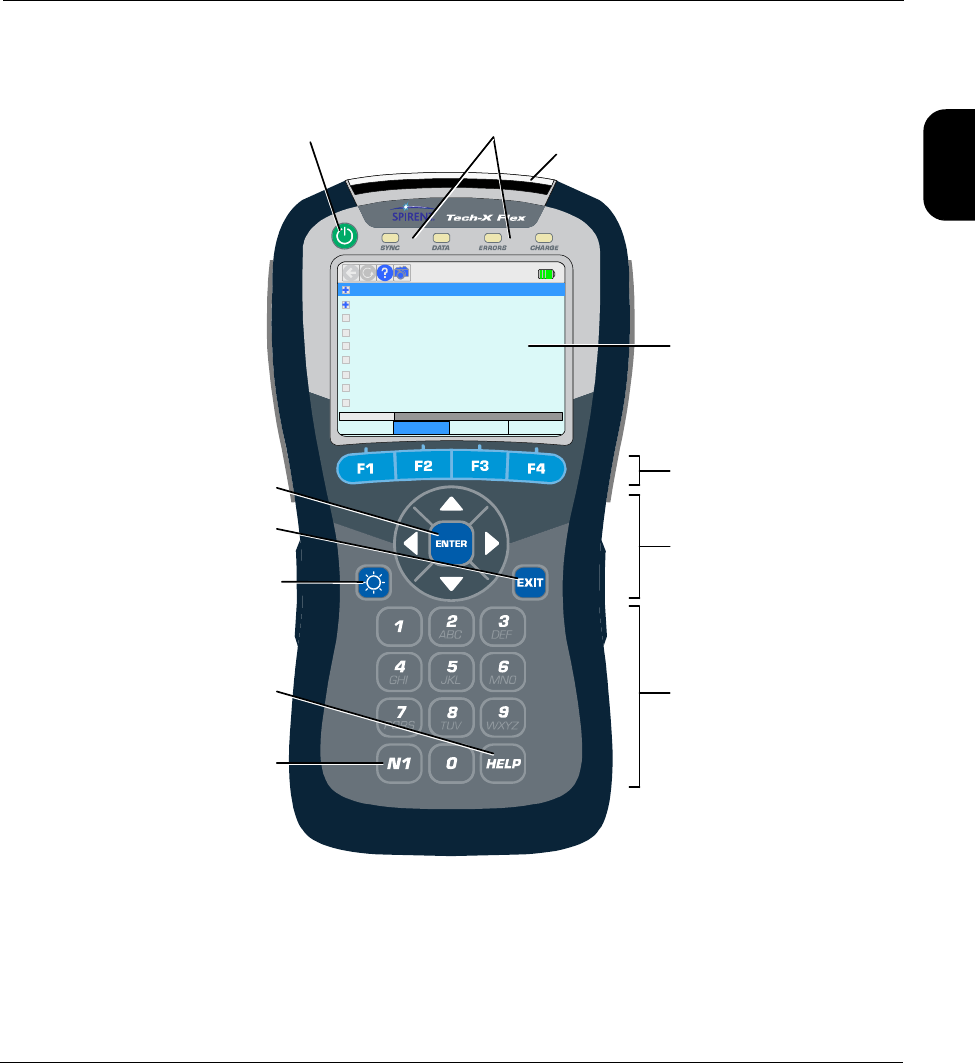
1.3.4 Front panel controls
Figure 1-1 Front panel controls
6: Web Browser
2: IP Network Setup
3: Connection Info
4: Ping
5: Traceroute
0: Wi-Fi Setup – 802.11bgn
MoCA-RF Wi-Fi 10/100/1G System
[Wi-Fi]
7: Packet Loss Test
8: Throughput
1: Wi-Fi Setup – 802.11ac
Touchscreen
display
Power on/off LED indicators
Function keys
Alphanumeric
keypad
(physical)
Enter
Exit
Brightness
Help
N1
Strap mount
Arrow keys

Verizon Base Unit User Guide Rev B PRELIMINARY 3/20/2014 Tech-X Flex® (P5)
1-6
Intro Wi-Fi 10/100 System IP/Video Specs
Table 1-1 Front panel feature descriptions
1.3.5 LED indicators
Indicator Function
Power on/off Powers the unit on and off, and is also used to place the unit into sleep mode (see
Powering on/off and sleep mode on page 1-10).
LED indicators See LED indicators on page 1-6.
Strap mount See Attaching the strap on page 1-11.
Enter Engages the active control on the screen, such as a button or a text entry box.
Exit Halts the current action or test, often returning the display to the previous screen.
Brightness Adjusts the brightness of the display. Also, this button can be used to take a screen
capture (see Capturing a screen image (screenshot) on page 1-17).
Help Used as a backspace on the text entry pad. Future versions will include onscreen
help launched with this button.
N1 Used for miscellaneous, specialized functions. For example, it is used to enter
special characters on the standard keypad, such as periods. For more information,
see Running a function or test on page 1-13.
Function keys Used to select the active test interface and/or functional area, such as the Wi-Fi
interface or the System configuration menu.
Arrow keys Provide navigational control over numerous display items, such as scroll bars,
multi-item lists, parameter entry screen controls, tabs, and more.
Alphanumeric
keypad
Used for text entry.

Tech-X Flex® (P5) Verizon Base Unit User Guide Rev B PRELIMINARY 3/20/2014
1-7
Intro
Wi-Fi
10/100
System
IP/Video
Specs
Table 1-2 LED indicator description
Indicator Function
SYNC Indicates the status of the link over the active interface. For example, when using the Wi-
Fi interface, the LED indicates the status of the Wi-Fi link. The general behavior is as
follows:
•Solid green - The unit is properly linked and/or synchronized with a comparable far-
end device. For the 10/100/1G interface, the LED is solid green any time the interface
is configured with IP information, but does not necessarily indicate that the information
is valid and routable.
•Red - The unit is attempting to configure the active interface and/or link with a far-end
device.
Note that some module interfaces use the SYNC LED differently. For module-specific
LED behavior, see the respective module documentation.
DATA Flashes when sending or receiving data over the active interface. For example, when
using the 10/100/1G interface, the LED flashes when an Ethernet frame is sent or
received.
ERRORS Indicates errors at the data link level on the active data stream. For example, on the
10/100/1G interface, the LED may indicate Ethernet frame CRC errors.
CHARGE Indicates power source and charging status, as follows:
•Solid red - Unit is connected to an external power source and the battery is charging
•Solid green - Unit is connected to an external power source and the battery is nearly
or fully charged
•Off - Unit is not connect to external power (unit on or off) and/or the unit has no battery
installed
Note that the unit includes a system feature for reporting detailed information about
battery status. For more information, see Battery Status on page 4-9.
Verizon Base Unit User Guide Rev B PRELIMINARY 3/20/2014 Tech-X Flex® (P5)
1-8
Intro Wi-Fi 10/100 System IP/Video Specs
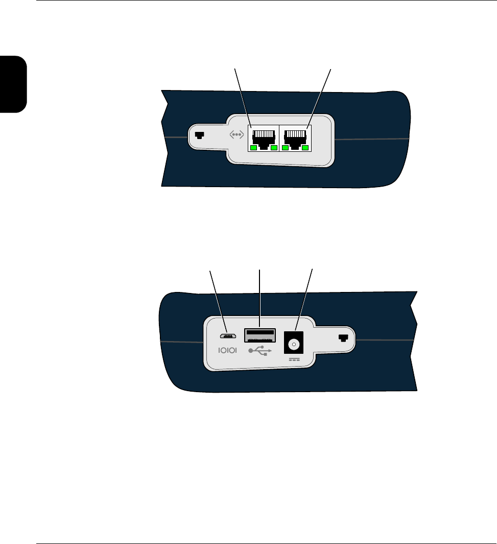
1.3.6 Base unit physical interfaces (ports)
Figure 1-2 Base unit right side
Figure 1-3 Base unit left side
Note the following:
• Modules have their own physical interfaces. See the documentation for the respective module for
more information.
• The two Ethernet interfaces are used for 10/100/1G testing and for administrative functions on the
unit, such as upgrading firmware. LED behavior is as follows:
Ethernet (10/100/1G) port 1
1-2
Ethernet (10/100/1G) port 2
Special use only
Do not connect
unless specifically
instructed!
12V
External power/
charge
Standard
USB port
2A

Tech-X Flex® (P5) Verizon Base Unit User Guide Rev B PRELIMINARY 3/20/2014
1-9
Intro
Wi-Fi
10/100
System
IP/Video
Specs
– When connected to a 10/100 network, the LED towards the bottom of the base unit will illuminate
green and flash when there is data activity
– When connected to a 1G network, the LED towards the top of the base unit will illuminate green
and flash when there is data activity
• The USB port is used for specialized functions related to transferring files to and from the unit. This
port and related functions are described elsewhere in the product documentation as applicable.
1.3.7 Unit symbols
The following table describes symbols that may appear on the physical body of the unit.
Table 1-3 Unit symbols
1.4 General product handling and operation
This section provides basic information for general operation. For most functions and tests, the buttons,
display, and other components operate in a similar fashion. Once you become familiar with general
operation, you should be able to set up and run most functions and tests, referring to this document only
as necessary for specific technical details, contained elsewhere in this document.
Symbol Description
DC power input.
Ethernet port.
Port for special use only. Do not plug anything into this port unless
specifically instructed by Spirent. Improper use could damage the unit.
USB port.
A symbol which may appear on the unit indicating that this documentation
should be reviewed thoroughly before using the product.

Verizon Base Unit User Guide Rev B PRELIMINARY 3/20/2014 Tech-X Flex® (P5)
1-10
Intro Wi-Fi 10/100 System IP/Video Specs
1.4.1 Protection from water and dust ingress
Although the basic unit provides some protection from water and dust ingress for outdoor use, Spirent
recommends the use of the optional jacket to increase the level of protection. For information about
purchasing the jacket, please contact your account representative.
1.4.2 Powering on/off and sleep mode
When the unit is off, the power button turns it on. When the unit is on, the power button prompts you
whether to power off the unit or to place it into sleep mode. Sleep mode allows the unit to save power but
return to active testing more quickly than a full boot up. To restore the unit from sleep mode, press the
power button once again. Note that the restoration process causes the unit to recheck module and
licensing status, after which it returns the screen to the default menu, not necessarily the menu that was
active when sleep mode was activated.
The unit supports automatic sleep mode activation after a specified amount of idle time. For more
information, see System/Module Settings > Base Unit on page 4-15.
1.4.3 Attaching, detaching, and handling modules
CAUTION: Before attaching or detaching a module, the unit must be powered off or
placed into sleep mode. Failure to do this could result in damage to the module
or base unit firmware. For more information on initiating sleep mode, see
Powering on/off and sleep mode on page 1-10.
NOTE: To prevent damage to the module bay and to keep electrical connections clean, you should
keep the module placeholder (the “dummy” module) installed when no module is in use. New
units are shipped with the placeholder attached.
Modules are fastened to the base unit using fastener screws attached to the upper “feet” of the unit. To
remove a module, loosen/disengage the two screws and gently pull the module from its electrical
connection. Likewise, to attach a module, gently press the module into the base unit to seat the electrical
connection, then finger-tighten the screws.

Tech-X Flex® (P5) Verizon Base Unit User Guide Rev B PRELIMINARY 3/20/2014
1-11
Intro
Wi-Fi
10/100
System
IP/Video
Specs
Figure 1-4 Rear of unit with a module installed, showing the fastener screws
Once a module is attached and has booted up, a menu corresponding to the module functionality will
appear over the F1 function key. For example, when the MoCA/RF module is attached, the F1 menu
shows “MoCA-RF.” If no module is attached, the F1 key shows no menu.
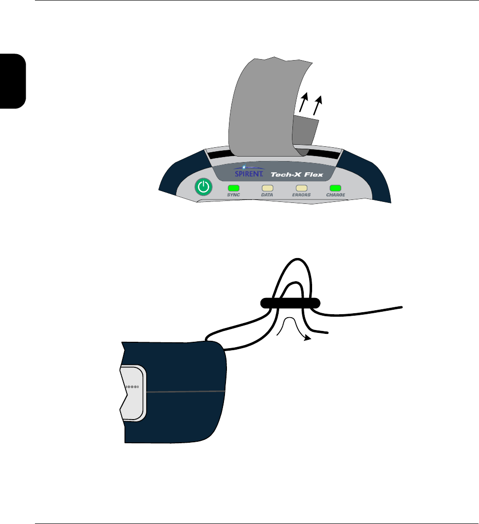
1.4.4 Attaching the strap
A strap with a hook is provided to hang the unit while working. To attach the strap, first make sure that the
buckle is facing up, then slide the open end around and through the strap mount at the top of the unit:
Module
Fastener screws
Verizon Base Unit User Guide Rev B PRELIMINARY 3/20/2014 Tech-X Flex® (P5)
1-12
Intro Wi-Fi 10/100 System IP/Video Specs
Figure 1-5 Sliding the open strap end through the strap mount
Next, feed the open end through the bottom of the buckle as shown in the following figure:
Figure 1-6 Feeding the strap through the buckle
(To hook)
Strap end
2
Strap end
(To hook)
Buckle

Tech-X Flex® (P5) Verizon Base Unit User Guide Rev B PRELIMINARY 3/20/2014
1-13
Intro
Wi-Fi
10/100
System
IP/Video
Specs
1.4.5 About the touchscreen display
The unit display includes touchscreen functionality which allows you to operate most display controls by
touching the screen. You should use the provided stylus or a similar device. It is recommended to avoid
using your fingers because it is difficult to control selections with precision.
CAUTION: Never use a sharp or metallic object, pen, pencil, or other such instrument
which will mar the screen.
For new units, units with new firmware, or units with a new battery, a calibration of the touchscreen
should be performed. For more information, see Cal Touchscreen on page 4-10.
1.4.6 Selecting the active interface
While testing with the unit, the first step is to select the appropriate interface with one of the function
keys, such as the 10/100/1G or Wi-Fi interface, or perhaps another interface associated with an attached
module. The interface and any associated hardware remain active only while testing in the respective
area continues. If you switch to a different interface, the previous interface shuts down and loses its IP
configuration, if any. For example, if you switch from the Wi-Fi interface to the 10/100/1G interface, the
Wi-Fi interface will shut down and any IP configuration will be lost.
An exception exists with the Wi-Fi interface, which can be optionally configured to remain active all the
time. For more information, see System/Module Settings > Base Unit on page 4-15.
1.4.7 Running a function or test
To run any function or test, the following steps generally apply:

Verizon Base Unit User Guide Rev B PRELIMINARY 3/20/2014 Tech-X Flex® (P5)
1-14
Intro Wi-Fi 10/100 System IP/Video Specs
1. Using the function keys or the touchscreen, select the correct menu/interface.
2. Using the up/down arrows, number pad, and/or touchscreen, select the desired menu item and
possibly submenu items to activate the desired function/test.
3. For tests that require input parameters, adjust those parameters as necessary, using the navigation
arrows and/or touchscreen. For free-form text entries, place the cursor in the field and press any
number key (or “double-tap” the field on the touchscreen) to produce the text entry keypad.
Using the onscreen keypad and/or the physical number keys, enter the desired data. Note the
following:
• The standard keypad is similar to a standard text message device, where you must press a key
multiple times to cycle through the associated letters. For example, to enter a “b”, press the “2”
key three times quickly, then pause.
• On the standard keypad, the N1 key allows you to enter special characters, such as a period. On
the QWERTY keypad, the N1 key has no effect, as all special characters are entered directly from
the “numeric screen” of the QWERTY keypad.
A function key selects the
function/test/menu directly above
Wi-Fi 10/100/1G System
8: Throughput
MoCA-RF
Standard keypad
Toggle keypad type
“QWERTY” keypad
Toggle between
numeric and alphabetic

Tech-X Flex® (P5) Verizon Base Unit User Guide Rev B PRELIMINARY 3/20/2014
1-15
Intro
Wi-Fi
10/100
System
IP/Video
Specs
• If you enter a value that is out of range for the underlying entry field, the Enter key on the screen
becomes disabled (grayed out). For example, if the underlying field requires a value from 1-99
and you type “100” into the keypad, the Enter key will become disabled when you type the
second “0”.
• In the System menu, you can set the default keypad type that appears when you initiate text
entry (see System/Module Settings > Base Unit on page 4-15).
•The Help button on the physical keypad acts as a backspace.
4. Press the appropriate button to start the respective action, normally Start or OK.”
NOTE: The unit is designed to be controlled by either the keypad or the touchscreen, or a combination
of both. You should become familiar with both methods of unit control, because you may find
that a combination of the two provides the most efficiency.
1.4.8 Repeating a function or test
See the “retest” button under Screen title bar buttons/icons on page 1-15.
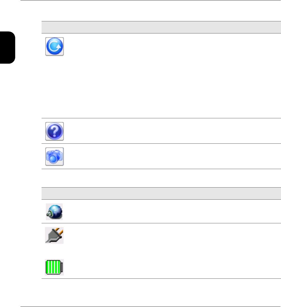
1.4.9 Screen title bar buttons/icons
The following table describes the buttons and icons that may appear in the title bar of menu and testing
screens:
Table 1-4 Title bar buttons
Image Name Description
Back Returns to the previous screen or the most logical previous menu. In many
cases, this button has the same effect as the Back button on the physical
keypad.
Verizon Base Unit User Guide Rev B PRELIMINARY 3/20/2014 Tech-X Flex® (P5)
1-16
Intro Wi-Fi 10/100 System IP/Video Specs
Table 1-5 Title bar icons
Retest Repeats (reruns) the most recent function/test, using the same setup as the
previous test. Note the following:
• This feature can also be invoked by pressing the N1 key on the physical
keypad.
• Only the most recent test can be repeated. For example, you can’t run a ping
test, then a traceroute, then repeat the ping test.
• Whenever a new test setup screen is entered, the unit automatically disables
this button.
• In any other case, if this button is disabled and the N1 key does nothing, a
retest is not feasible due to technical limitations. For example, if you run a test
with the MoCA-RF module and then switch to the 10/100/1G testing menu, the
MoCA/RF hardware will shut down and prevent a repeat of any previous test.
Help Launches the online help system, which produces an onboard viewer of this
document set.
Capture
screen
Launches a screen capture. For more information, see Capturing a screen image
(screenshot) on page 1-17.
Button Description
Indicates that an Admin Port is currently configured (see Admin Port on page 4-6).
-or-
The unit is plugged into an external power source
-or-
The unit is using battery power. For this icon, the number of green bars provides a rough
indication of remaining charge. For comprehensive details on current battery status, use
System > Battery Status (see Battery Status on page 4-9).
Image Name Description
Tech-X Flex® (P5) Verizon Base Unit User Guide Rev B PRELIMINARY 3/20/2014
1-17
Intro
Wi-Fi
10/100
System
IP/Video
Specs
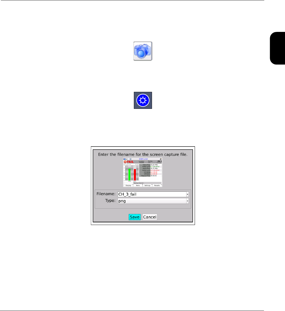
1.4.10 Capturing a screen image (screenshot)
Most screens provide a screen capture feature, invoked with the screen capture button in the title bar:
Figure 1-7 Screen capture button (title bar)
...or by pressing and holding the brightness button on the physical keypad:
Figure 1-8 Brightness button (physical keypad)
Following the initial capture, the unit produces a screen that allows you to specify a filename and image
file type, after which the image is saved to the Record Manager.
Figure 1-9 Screen capture screen
Note the following:
• For more information on managing and downloading screen capture files, see Record Manager on
page 4-1.
• To capture extended drop-down lists, focus indicators, and other field-oriented artifacts, you must use
the brightness button for the capture. The title bar button will remove the focus from the current field,
collapsing any lists, etc.

Verizon Base Unit User Guide Rev B PRELIMINARY 3/20/2014 Tech-X Flex® (P5)
1-18
Intro Wi-Fi 10/100 System IP/Video Specs
• When using the brightness button for the capture, the screen brightness will change momentarily,
then return to the original setting once the capture is taken.
• For most screens, the PNG (Portable Network Graphics) format provides the best compromise
between image quality and file size. The BMP (bitmap) format provides lossless quality (that is,
produces an exact replica), but uses a larger file size.
1.4.11 Stopping a test
Some tests provide a “stop” shortcut (typically F3 or F4) which may be required to stop the test. For most
other tests, the EXIT key will stop a test immediately. Also, the “back” button in the upper left corner of
the screen may sometimes be used instead of EXIT. Some tests may require a small amount of
shutdown time before terminating completely.
1.4.12 Saving results
Most tests allow you to save the results using the Save button on the results screen (F4 key). For some
long-running continuous tests, the F4 key shows the command Save Start instead, which causes results
to be saved continuously until the test is stopped or F4 is pressed again. Other continuous tests do not
allow results to be saved until the test is stopped.
When you initiate a Save action, the unit prompts you for the results file to which the results should be
written. You can either select an existing file or type a new filename to create a new file. If you select an
existing file, the unit will prompt you whether to append to or overwrite the file. If you create a new file, it
becomes part of the normal record file collection that can be managed using the Record Manager (see
Record Manager on page 4-1).
NOTE: To account for ranging, custom settings, and other factors, some tests may use different units to
display the same result. For example, a resistance measurement with the WB Copper Module
might display results in ohms, kohms, or MOhms. For consistency, however, saved results
always use the same units, with conversion from the results screen units as necessary.
1.4.13 Maximum test duration for continuous tests
For any test that can run continuously, such as a video quality of service test, the maximum duration is
four hours.
1.4.14 Interpreting results
In some cases, this document and related documents provide results samples and references to industry
standards for pass/fail criteria. None of this information should be construed as a recommendation or

Tech-X Flex® (P5) Verizon Base Unit User Guide Rev B PRELIMINARY 3/20/2014
1-19
Intro
Wi-Fi
10/100
System
IP/Video
Specs
mandate on how any given organization should interpret results. In all cases, you should consult local
and corporate protocol for the standards by which you interpret results. This document does not intend in
any way to serve as an authorized or approved standard for the operation and maintenance of any
telecommunications network.
1.4.15 Important MoCA module compatibility note
The “next generation” (P5) base unit is designed for use with the newer combined MoCA/RF module.
The older, standalone MoCA module may be used with this base unit; however, some anomalies may be
present due to the older feature set supported by that module. Most notably, the standalone module
supports the MoCA standard up to v1.1 only, which may result in the following behavior:
• On a bandwidth table, the bandwidth between any v2.0 nodes will display as zero, because it cannot
be read.
• For v2.0 nodes, the bit loading graphs on the statistics pages will be inaccurate.
Other behavioral aberrations may occur. Therefore, it is recommended to use the combined module
whenever possible.
1.5 Remote control of the unit
With a VNC client on a PC or mobile device, you can operate the unit remotely over a network
connection, instead of using the actual touchscreen and physical keypad.
1.5.1 About VNC
VNC (Virtual Network Computing) is a technology that allows the graphical interface of one computer
(such as the display screen of the unit) to be rendered on another networked computer, where it can be
operated as if it were the original. In the case of the Tech-X Flex, VNC control means that the screen can
be displayed on a client PC or mobile device, where:
• On a PC, the unit accepts mouse clicks and keyboard entries on the VNC screen as if they were
physical touches on the touchscreen and keypad entries, respectively.
• On a mobile device, the device touchscreen assumes identical functionality to the unit touchscreen,
with respect to taps and other physical interactions.
In all cases, when the screen is manipulated on the PC or mobile device, the actual screen on the unit
responds and changes as if it were being used directly.
Many users may find important uses for VNC remote control, such as:

Verizon Base Unit User Guide Rev B PRELIMINARY 3/20/2014 Tech-X Flex® (P5)
1-20
Intro Wi-Fi 10/100 System IP/Video Specs
• A technician who needs to physically connect the unit at some place, then work at other locations
while running tests.
• A technician or manager at a remote location (perhaps a support center) who needs to see and/or
operate a unit currently in use at a subscriber site.
• Any person who might need to render the interface on another computer for training, reporting, and/or
screen capture activities.
In all cases, the PC or mobile device to be used for remote control must have a VNC client (viewer)
application installed. For more information:
• On installing a VNC viewer, see Installing a VNC client (viewer) on page 1-20.
• On VNC as a general technology, visit http://en.wikipedia.org/wiki/Virtual_Network_Computing.
1.5.2 Installing a VNC client (viewer)
From the factory, the unit firmware includes a display driver that is ready to serve the screen to a VNC
client running on another computer. Therefore, the preliminary requirement to VNC control is the
installation of that client. The following table provides some recommendations for clients tested by
Spirent:
Table 1-6 VNC client support/installation
Note that other hardware platforms, operating systems, and/or VNC clients may also allow proper remote
control. However, is not feasible for Spirent to track and test all of them. If you would like to use a different
client, etc., you should feel free to test it and implement the solution once you are comfortable with its
reliability.
RealVNC 4.1.3 installation and setup
RealVNC 4.1.3 can be downloaded from:
Platform VNC client support/installation
Windows operating
system (PCs and
mobile devices)
VNC control has been tested with the following versions of RealVNC viewer:
•4.1.3 - See RealVNC 4.1.3 installation and setup on page 1-20
•5.0.5 - See RealVNC 5.0.5 installation and setup on page 1-21
Android operating
system (mobile
devices)
VNC control has been tested with the Mocha VNC Lite app, v2.1. The app is
free and may be downloaded from the normal app store on the device. Follow
the instructions provided during the download/installation.

Tech-X Flex® (P5) Verizon Base Unit User Guide Rev B PRELIMINARY 3/20/2014
1-21
Intro
Wi-Fi
10/100
System
IP/Video
Specs
http://www.filehippo.com/download_realvnc/changelog/4977
Once the EXE file is downloaded, run the file and follow the wizard prompts. Default installation settings
are adequate to establish proper functionality; however, if you have expertise with the software, you may
choose some customizations. For example, you could choose not to install the VNC server component,
as the client component is the only necessary component.
Once installed, RealVNC has a variety of options related to VNC connections, accessible from the setup
screen and from a VNC window. Normally, default settings are adequate, however the following settings
may require attention:
•Colour level (Colour & Encoding tab) - If you notice problems with performance or other display
functionality, consider trying a different setting such as Low or Full.
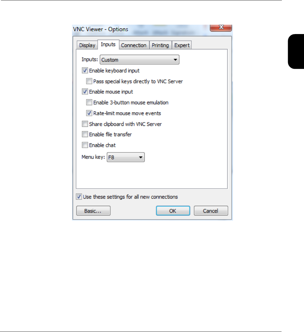
•Pass special keys directly to server (Inputs tab) - Normally, this setting should be unchecked for
best results. If checked, you may have trouble with operations such as using a PC PrtScn key to
capture a screenshot, because the keyboard input will be passed to the unit, not the PC.
•Rate-limit mouse move events (Inputs tab) - Normally, this setting should be checked for best
results. This setting limits the amount of hover/movement-related events sent to the unit, which are
less critical for proper operation. Without this setting, on fast networks the unit may receive more
input than necessary, causing a processing backlog and thus delays in control.
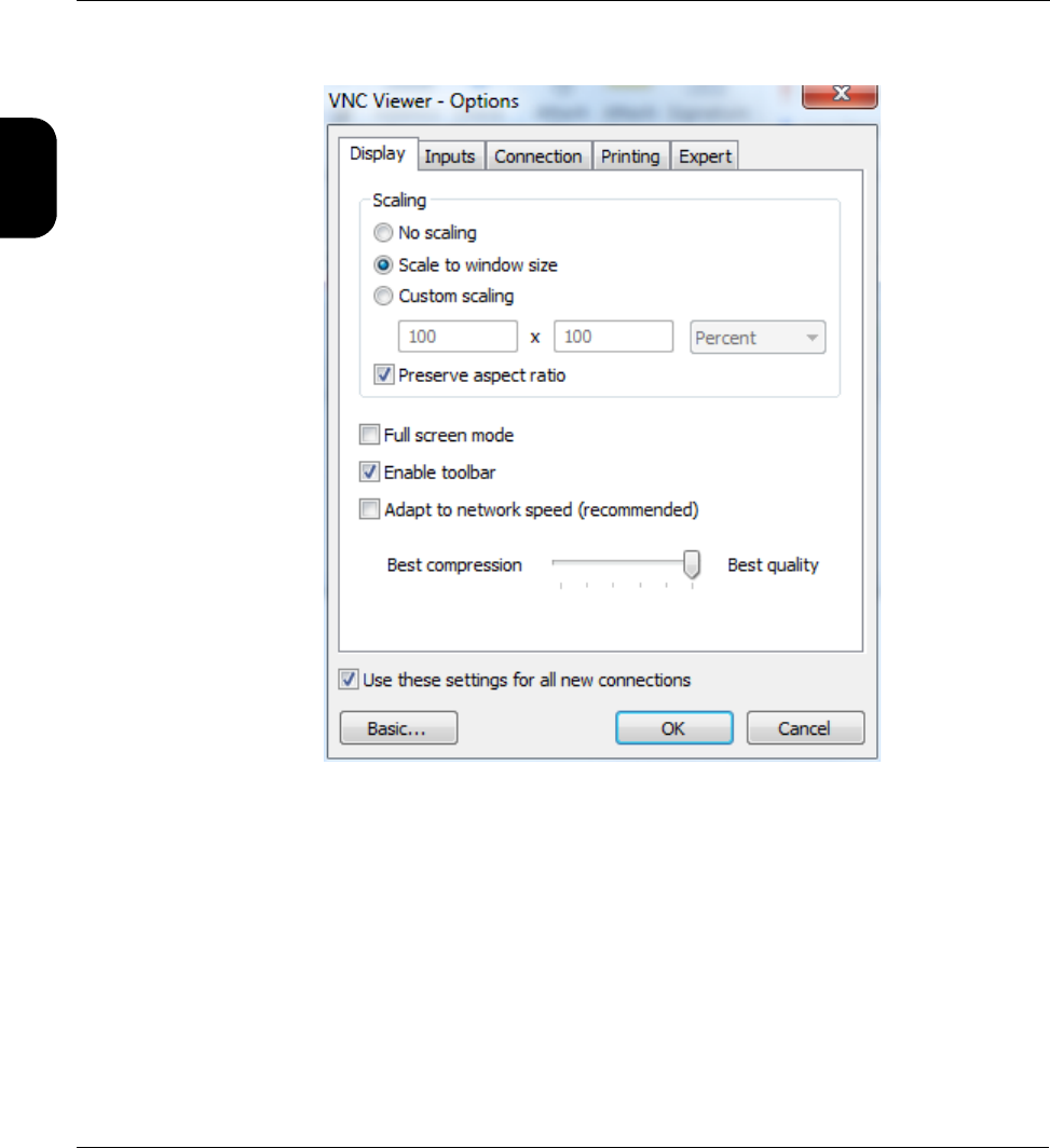
RealVNC 5.0.5 installation and setup
RealVNC 5.0.5 can be downloaded from:
http://www.realvnc.com/download/viewer/
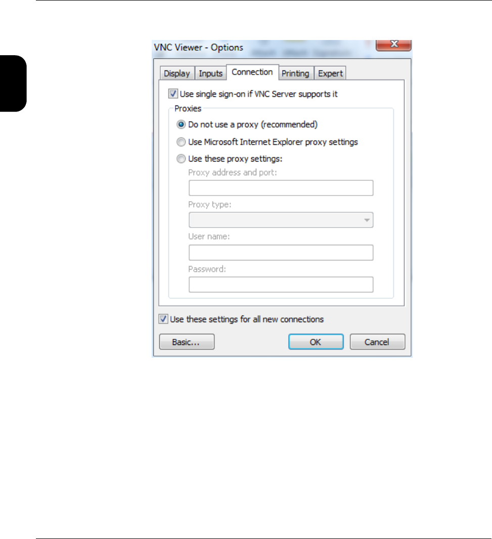
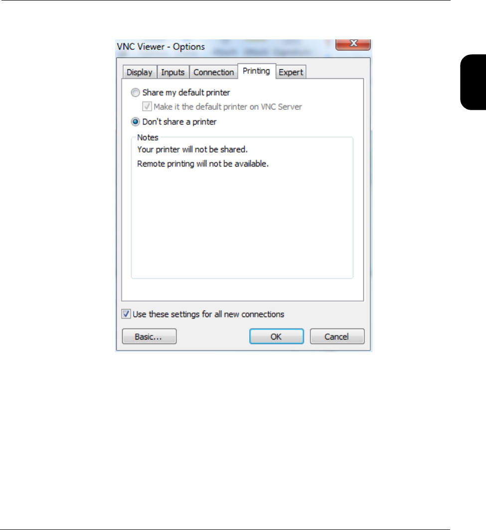
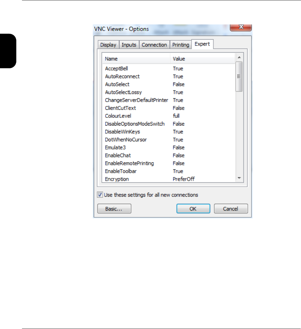
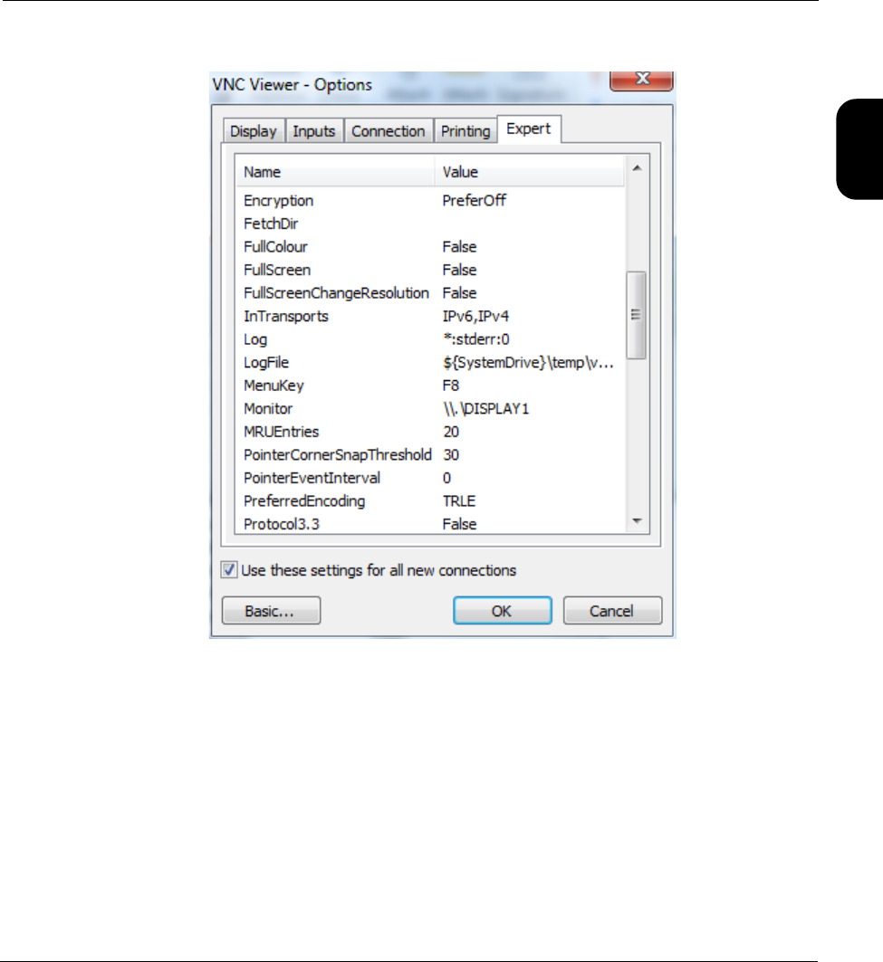
Once installed, the Advanced options (accessible with the Options button) must be configured as
follows:
Verizon Base Unit User Guide Rev B PRELIMINARY 3/20/2014 Tech-X Flex® (P5)
1-22
Intro Wi-Fi 10/100 System IP/Video Specs
Figure 1-10 Advanced options - Display tab
Tech-X Flex® (P5) Verizon Base Unit User Guide Rev B PRELIMINARY 3/20/2014
1-23
Intro
Wi-Fi
10/100
System
IP/Video
Specs
Figure 1-11 Advanced options - Inputs tab
Verizon Base Unit User Guide Rev B PRELIMINARY 3/20/2014 Tech-X Flex® (P5)
1-24
Intro Wi-Fi 10/100 System IP/Video Specs
Figure 1-12 Advanced options - Connection tab
Tech-X Flex® (P5) Verizon Base Unit User Guide Rev B PRELIMINARY 3/20/2014
1-25
Intro
Wi-Fi
10/100
System
IP/Video
Specs
Figure 1-13 Advanced options - Printing tab
Verizon Base Unit User Guide Rev B PRELIMINARY 3/20/2014 Tech-X Flex® (P5)
1-26
Intro Wi-Fi 10/100 System IP/Video Specs
Figure 1-14 Advanced options - Expert tab (First set)
Tech-X Flex® (P5) Verizon Base Unit User Guide Rev B PRELIMINARY 3/20/2014
1-27
Intro
Wi-Fi
10/100
System
IP/Video
Specs
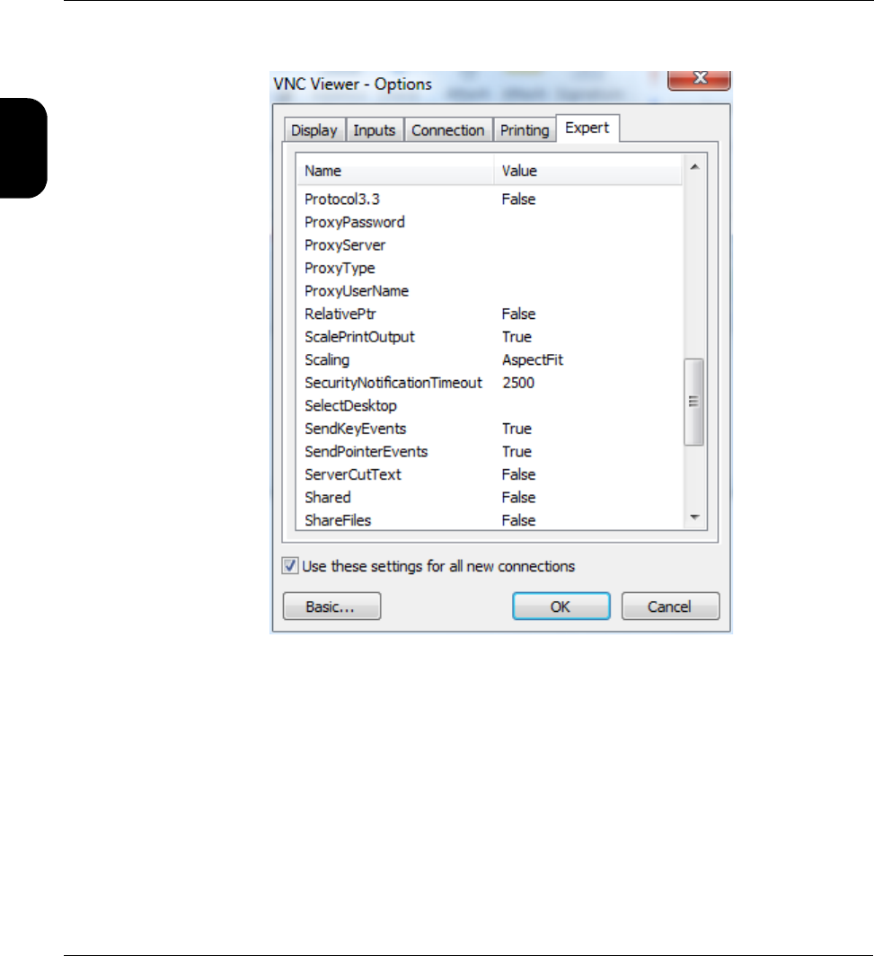
Figure 1-15 Advanced options - Expert tab (Second set)
Verizon Base Unit User Guide Rev B PRELIMINARY 3/20/2014 Tech-X Flex® (P5)
1-28
Intro Wi-Fi 10/100 System IP/Video Specs
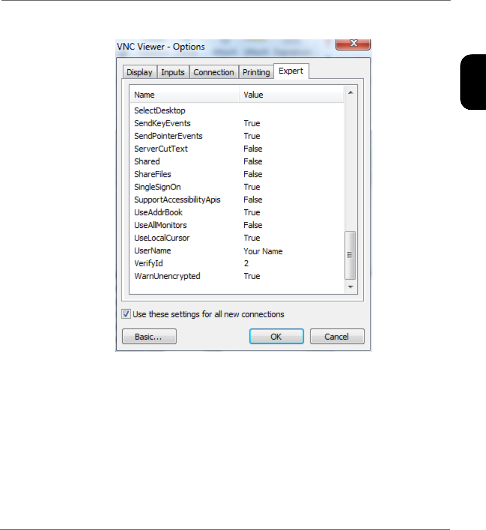
Figure 1-16 Advanced options - Expert tab (Third set)
Tech-X Flex® (P5) Verizon Base Unit User Guide Rev B PRELIMINARY 3/20/2014
1-29
Intro
Wi-Fi
10/100
System
IP/Video
Specs
Figure 1-17 Advanced options - Expert tab (Fourth set)
1.5.3 Remote control setup scenarios
To establish a remote control session over VNC, an IP connection is required between the built-in VNC
server on the unit and a VNC client on a separate PC, tablet, or smartphone device. This IP connection
may be made using one of the following scenarios:
•Local remote control (via a router/LAN) setup on page 1-30
•Local remote control (via ad hoc Wi-Fi) setup on page 1-31
•Remote site remote control (via the internet) setup on page 1-33
Verizon Base Unit User Guide Rev B PRELIMINARY 3/20/2014 Tech-X Flex® (P5)
1-30
Intro Wi-Fi 10/100 System IP/Video Specs
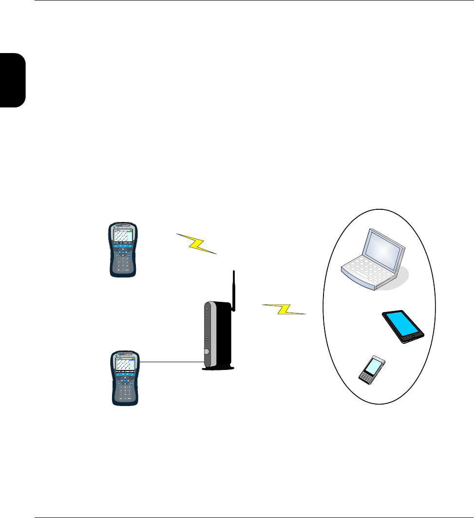
Local remote control (via a router/LAN) setup
This setup is intended to allow local remote control over a residential LAN or similar. For example, it
might be used by a technician who needs to connect the unit at some point on a residential network, then
control the unit from elsewhere in the residence.
With this setup, the unit connects to a switch or router device (such as a BHR) with either:
• A Wi-Fi link, or
• An Ethernet/Cat-5 cable
The VNC client device then connects to same network (often through the same router), typically over a
standard Wi-Fi link. Once both devices are fully networked at the IP level, the VNC client application can
initiate a remote control session. Consider the following diagram. which represents a typical residential
configuration with a BHR:
Figure 1-18 Remote control over an Admin Port connection
This type of remote control allows access to nearly all test and management functions on the unit,
including module testing menus. To set it up:
-or-
-or-
Wi-Fi
BHR
Wi-Fi
VNC
client
10/100
Admin Port
Ethernet
Wi-Fi
Admin Port
-or-

Tech-X Flex® (P5) Verizon Base Unit User Guide Rev B PRELIMINARY 3/20/2014
1-31
Intro
Wi-Fi
10/100
System
IP/Video
Specs
1. If you plan to use a 10/100/1G Admin Port, connect the unit to the router with a physical 10/100
(Ethernet) cable.
2. Set up a Wi-Fi Admin Port or a 10/100/1G Admin Port on the unit, as applicable (see Admin Port on
page 4-6).
NOTE: Remote control over a Wi-Fi Admin Port will not allow access to functions within the Wi-Fi
menu (F2).
3. Note the IP address that was assigned and then initiate the VNC session on the client device (see
Initiating a VNC connection on the client on page 1-36).
Local remote control (via ad hoc Wi-Fi) setup
NOTE: This feature is available as a purchasable option. For more information, see Licensed feature
details on page 1-40.
This setup is intended to allow local remote control over a direct connection to the unit. For example, it
might be used by a technician who needs to physically connect the unit at some point on a residential
network, then control the unit from elsewhere in the residence. Because the devices connect directly, it
may be more convenient than using the residential LAN to establish connectivity.
This setup uses an “ad hoc” Wi-Fi network to connect the unit and the VNC client device. The unit
establishes itself as the network source and the client device then joins that network. For this method to
work, the client device must support the capability to join an ad-hoc Wi-Fi network. Consider the following
diagram:
Figure 1-19 Remote control over an ad-hoc Wi-Fi connection
-or-
-or-
Ad hoc Wi-Fi VNC
client
Verizon Base Unit User Guide Rev B PRELIMINARY 3/20/2014 Tech-X Flex® (P5)
1-32
Intro Wi-Fi 10/100 System IP/Video Specs
NOTE: An ad hoc network is a special type of decentralized network where devices form IP connectivity
directly with one another. No external routing devices are used and therefore the network does
not provide any direct access to any larger network. Further technical information on ad hoc
networks is beyond the scope of this document. For more information, visit
http://en.wikipedia.org/wiki/Wireless_ad_hoc_network.
This type of remote control allows access to nearly all test and management functions on the unit except
testing within the Wi-Fi menu (F2). To set it up:
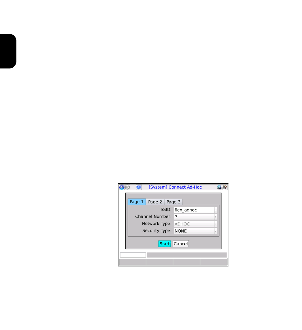
1. Select System > Admin Port > Wi-Fi Admin Port > Ad-Hoc Remote Control to begin setting up
the unit as an ad hoc network source.
2. In the Connect Ad-Hoc setup screen, configure standard Wi-Fi parameters, noting the following:
• You are creating a network, not connecting to one. Therefore, you decide what the SSID and
Channel Number should be, along with any kind of security you want to add, if any. Later, when
you connect to the network with the VNC client device, you will have to account for whatever
parameters you established. Normally, the primary concern is to establish a network with
parameters that do not interfere with any other Wi-Fi networks in the area.
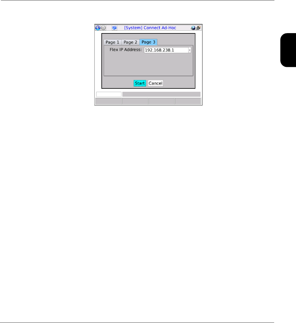
•On Page 3, you can specify a Flex IP Address which will be the address that the VNC client
device will use when sending traffic to the unit. Aside from this screen, the management of IP
addresses at both endpoints is transparent. Normally, the specific address is unimportant to
establishing connectivity and therefore the default address is adequate. However, be sure to note
the address that is specified, because you will need it when you initiate the VNC session on the
client device.
Figure 1-20 Connect Ad-Hoc screen (Page 1)
Tech-X Flex® (P5) Verizon Base Unit User Guide Rev B PRELIMINARY 3/20/2014
1-33
Intro
Wi-Fi
10/100
System
IP/Video
Specs
Figure 1-21 Connect Ad-Hoc screen (Page 3)
3. On the client device, use the standard Wi-Fi tools to locate and connect to the network you just
established.
4. With the IP address assigned to the unit on the ad hoc network, initiate the VNC session on the client
device (see Initiating a VNC connection on the client on page 1-36).
Remote site remote control (via the internet) setup
NOTE: This feature is available as a purchasable option. For more information, see Licensed feature
details on page 1-40.
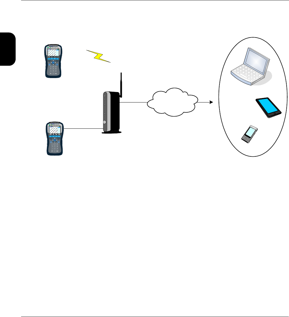
With this setup, the unit can be controlled over an internet connection, perhaps by a technician in a
remote support center. It assumes that the unit is connected on a LAN behind a UPnP-enabled router,
whose WAN side interface is configured with a public IP address. For example:
Verizon Base Unit User Guide Rev B PRELIMINARY 3/20/2014 Tech-X Flex® (P5)
1-34
Intro Wi-Fi 10/100 System IP/Video Specs
Figure 1-22 Remote control over an internet connection
This type of remote control allows access to nearly all test and management functions on the unit unless
you connect the unit over a Wi-Fi Admin Port, in which case all functions within the Wi-Fi menu (F2) will
be unavailable. To set it up:
1. At the subscriber site, if you plan to use a 10/100/1G Admin Port, connect the unit to the router with
a physical 10/100 (Ethernet) cable.
2. On the unit, set up a Wi-Fi Admin Port or a 10/100/1G Admin Port port (respectively) with
connectivity to the LAN, in a standard manner. For more information, see Admin Port on page 4-6.
3. Select System > Admin Port > WAN Remote Control > Enable WAN Remote Control. Note that
this step configures the router, in order to establish a VNC traffic path to the unit.
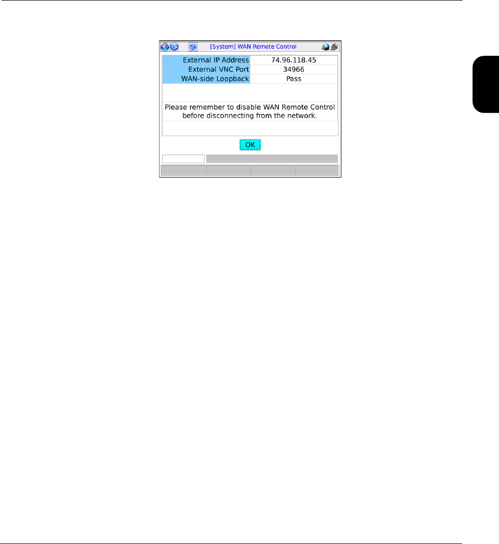
4. In the Enable WAN Remote Control results, make note of the following information which will be
required for the remote VNC client user:
•External IP Address - The address assigned to the WAN interface
•External VNC Port - The port that incoming VNC traffic must use
-or-
-or-
VNC
client
LAN
port
WAN
port
Internet
BHR
Wi-Fi
10/100
Admin Port
Ethernet
Wi-Fi
Admin Port
-or-
Tech-X Flex® (P5) Verizon Base Unit User Guide Rev B PRELIMINARY 3/20/2014
1-35
Intro
Wi-Fi
10/100
System
IP/Video
Specs
Figure 1-23 Enable WAN Remote Control results screen
Note the following:
• If this function fails, the router may not support UPnP management or it may have been
configured in a manner that prevents the unit from performing the necessary tasks. Router
administration is beyond the scope of this document. If you continue to have trouble, consult the
router documentation and/or a network specialist.
• In rare cases, this function will pass but report an address of 0.0.0.0. Again, certain router
configurations may cause this behavior. If you already know or can determine a valid WAN side
address, VNC control may still be possible.
• Following the router configuration, the unit attempts a test connection with the WAN interface,
using the newly-configured path. If the test is successful, it reports Pass for WAN-side
Loopback, which generally indicates that the path from the interface to the unit is good.
Otherwise, it reports Fail; however, note that hardware limitations and/or other anomalies may
obstruct the test and that the path may still be good. In other words, a result of Fail does not
necessarily indicate a problem and you should always attempt the VNC session anyway.
5. Forward the IP address and port to the remote VNC user, who must then launch a VNC session with
those parameters (see Initiating a VNC connection on the client on page 1-36).
6. When the VNC session is complete, select System > Admin Port > WAN Remote Control >
Disable WAN Remote Control to restore the router to its original configuration.
Additional technical details
This remote control functionality is based on port-forwarding technology that is typically supported by
residential routers. In summary, a router can be configured to accept packets at its public WAN address
using a specific port, then translate to a different port and forward the packets to a specific (non-public)
host on the LAN. In this manner, standard firewalls can remain in place, with a path for very specific
traffic to reach a specific LAN host.

Verizon Base Unit User Guide Rev B PRELIMINARY 3/20/2014 Tech-X Flex® (P5)
1-36
Intro Wi-Fi 10/100 System IP/Video Specs
In this case, the traffic is VNC and the host is the unit, whose VNC server expects traffic on port 5900.
During the Enable WAN Remote Control step, the unit configures the router to accept traffic on some
other port (as reported for External VNC Port) and forward the traffic to its LAN address on port 5900. In
this way, the unit appears to the VNC client as any other host on the internet and full VNC functionality is
supported. Note that this general methodology is commonly used by other devices such as internet-
based gaming systems, where non-public hosts must communicate with one another across the internet.
These systems automatically configure their respective routers much like the unit.
With respect to the persistence of the router configuration, note the following:
• If you never manually undo the router configuration (Disable WAN Remote Control), the forwarding
path may remain indefinitely. This may or may not be of concern. While it represents a path through
the firewall that did not exist previously, its scope is limited to traffic on port 5900 reaching the
address that the unit was using during the VNC session. A network administrator should provide
advice and procedures related to this possibility.
•The Disable WAN Remote Control setting is always enabled, in the event that it must be executed
some time in the future, perhaps some time after the end of the VNC session.
• Port forwarding can be manually configured through the administrative interface of a router. If you use
this interface to make changes to settings that were configured by the unit, the Disable WAN
Remote Control function may fail afterwards. Therefore, it is strongly recommended to allow the unit
to perform all router configuration tasks and to use the router interface only if absolutely necessary.
The unit uses UPnP (Universal Plug and Play) technology when configuring the router. UPnP has other
applications as well. For more information, see http://www.upnp.org/.
1.5.4 Initiating a VNC connection on the client
To initiate a VNC connection and thus begin a remote control session, you must first:
1. Be sure that a functional VNC client is properly installed on the client device (see Installing a VNC
client (viewer) on page 1-20).
2. Establish IP connectivity with the unit in a manner suitable for VNC control (see Remote control setup
scenarios on page 1-29).
Once these steps are complete and you know the IP address assigned to the unit, you can initiate a VNC
session as follows:
Initiating a VNC session with RealVNC
Tech-X Flex® (P5) Verizon Base Unit User Guide Rev B PRELIMINARY 3/20/2014
1-37
Intro
Wi-Fi
10/100
System
IP/Video
Specs
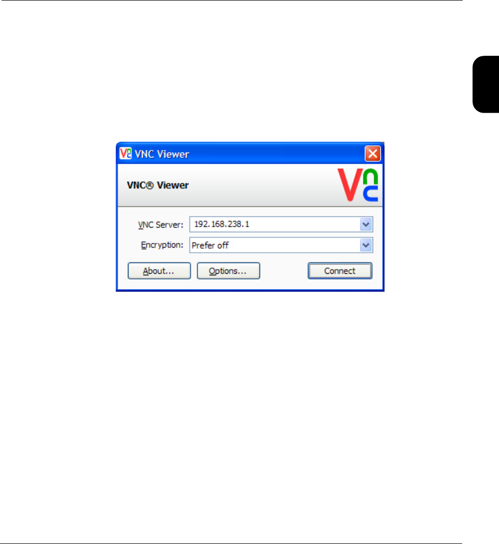
1. In the initial setup screen that appears when you launch the viewer, enter the IP address of the unit
and click OK.
NOTE: If you are connecting over the internet using the WAN Remote Control feature, you must
include a colon and the port expected on the subscriber router WAN interface. Otherwise, the
application will use the standard VNC port 5900, which will not transit the router. For more
information on internet-based remote control, see Remote site remote control (via the internet)
setup on page 1-33.
Figure 1-24 RealVNC v5.0.5 setup screen - Local remote control example
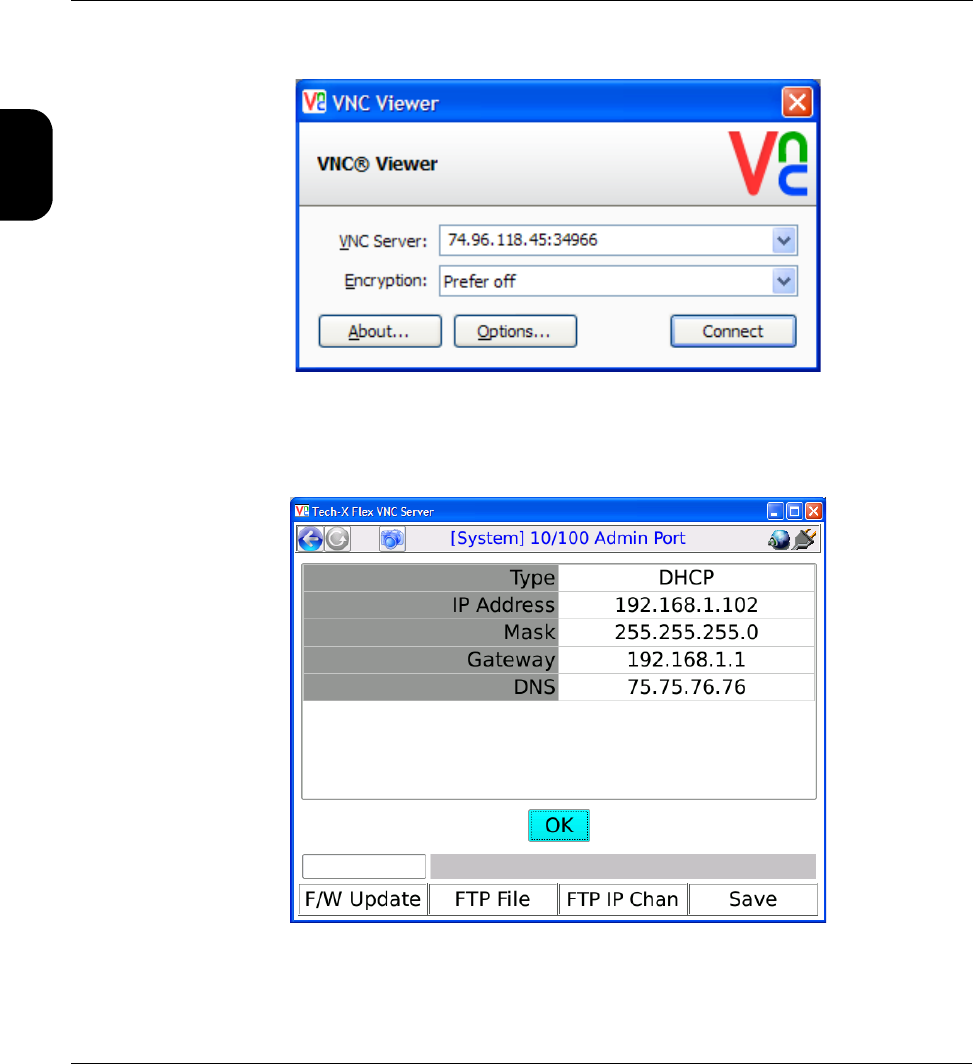
Verizon Base Unit User Guide Rev B PRELIMINARY 3/20/2014 Tech-X Flex® (P5)
1-38
Intro Wi-Fi 10/100 System IP/Video Specs
Figure 1-25 RealVNC v5.0.5 setup screen - Internet (remote site) remote control example
2. When the VNC window appears, operate the unit using the computer mouse, keyboard, etc. as if
operating the unit directly.
Figure 1-26 RealVNC window showing the unit screen
Initiating a VNC session with Mocha VNC Lite
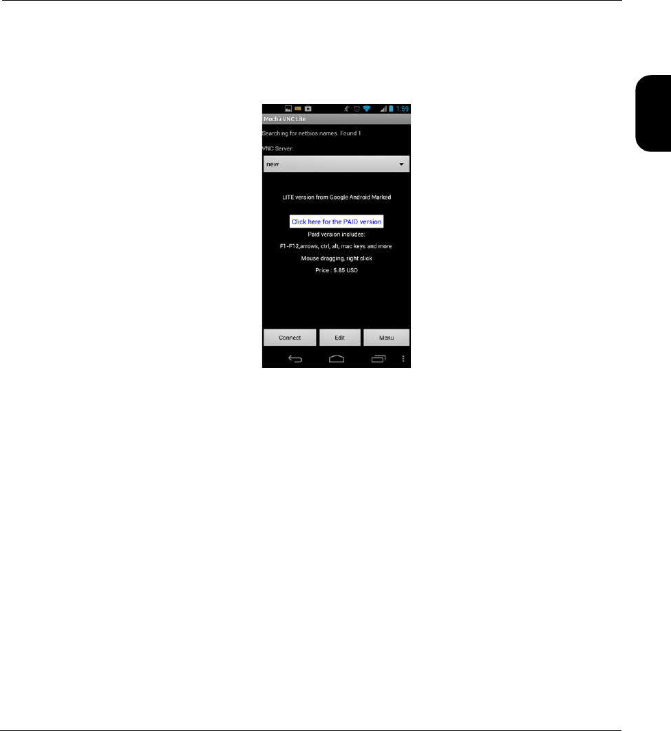
Tech-X Flex® (P5) Verizon Base Unit User Guide Rev B PRELIMINARY 3/20/2014
1-39
Intro
Wi-Fi
10/100
System
IP/Video
Specs
1. On the mobile device, make sure that the Wi-Fi interface is enabled. Refer to the documentation of
the specific device for more information.
2. Launch Mocha Lite.
Figure 1-27 Mocha VNC Lite initial setup screen
3. Tap Edit in the initial setup screen.
4. In the Edit session screen, configure the following:
•VNC Server IP - Enter the IP address of the unit.
•Password - Enter a pound sign (#) to indicate that no password is required.
•Port - Specify the destination TCP port, typically either:
The default of 5900 when using local remote control over a LAN or an ad hoc Wi-Fi network, or
The port reported for External VNC Port in the Enable WAN Remote Control results, when
controlling the unit over the internet (see Remote site remote control (via the internet) setup on
page 1-33).
...and tap Ok.
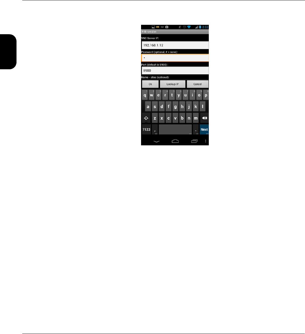
Verizon Base Unit User Guide Rev B PRELIMINARY 3/20/2014 Tech-X Flex® (P5)
1-40
Intro Wi-Fi 10/100 System IP/Video Specs
Figure 1-28 Mocha VNC Lite Edit session screen
5. When the VNC window appears, operate the unit using the mobile device touchscreen as if operating
the unit directly.
NOTE: Remember that you can double-tap any text entry field to produce the unit keypad, just like
when using the actual unit touchscreen.
1.6 Licensed feature details
The following table provides details on the optional licenses available for purchase and the specific
features that they control. Any feature not explicitly listed is normally functional without a special license
or license key. Note the following:
• In most cases, general module functionality does not require a separate license, as the purchase of
the physical hardware is considered a general operational license. However, some specific features
of certain modules may require a license. For details on any of the specific features listed in the table,
see the respective user guide.
• At any time, you can use the System menu to view the status of current licenses and enable features
with new license keys. For more information, see Licensed Options on page 4-11.

Tech-X Flex® (P5) Verizon Base Unit User Guide Rev B PRELIMINARY 3/20/2014
1-41
Intro
Wi-Fi
10/100
System
IP/Video
Specs
Table 1-7 License details
License Affected hardware
component Description
Bonded xDSL ADSL/VDSL2 Modem
module
Enables the Bonded xDSL feature, for use in only in
conjunction with the Custom DSL which does not
natively include Bonded xDSL.
CSM Constellation CSM module Enables the use of the Constellation graph, part of
the Level test results.
CSM Spectrum CSM module Enables the use of the Spectrum test (spectrum
analyzer).
CSM Home
Qualification
CSM module Enables the use of the Home Qualification test.
Note that this license:
• Also controls access to the separate Field
Management System (FMS).
• Enables the high-speed data portions of the test,
regardless of whether the separate High Speed
Data license is active.
CSM Return Path CSM module
DOCSIS module
Enables the use of the Return QAM Generator and
Return Path Generator (CSM only) tests.
Custom DSL ADSL/VDSL2 Modem
module
Provides a basic ADSLx synchronization license
towards the DSLAM only (Sync with DSLAM). It
does not allow Bonded xDSL or VDSL
synchronization, unless combined with the Bonded
xDSL and/or VDSL licenses.
DSL Auto ATM-PTM ADSL/VDSL2 Modem
module
Allows the unit to automatically detect ATM or PTM
mode on a synchronized ADSLx link and adjust IP
authentication routines accordingly. Without this
option, the basic ADSL synchronization step is not
limited, but IP authentication will not be possible if
the link is using PTM.
DSL Expert ADSL/VDSL2 Modem
module
Enables the specific DSL Expert Analysis feature.
Without this license, the DSL Expert Analysis menu
item is disabled.

Verizon Base Unit User Guide Rev B PRELIMINARY 3/20/2014 Tech-X Flex® (P5)
1-42
Intro Wi-Fi 10/100 System IP/Video Specs
Dual Ethernet Base unit Enables passive testing on the 10/100/1G interface.
More specifically, it allows the unit to be connected
in-line with an existing Ethernet link and mirror traffic
internally for analysis. Without this license, both
10/100/1G ports will operate normally for any other
type of testing, including the ability to bridge an
existing Ethernet link, but without traffic mirroring.
Dual MoCA MoCA module Allows the MoCA module to synchronize “in-line”
with a MoCA network; that is, act as a bridge for the
purpose of analyzing network traffic and related
testing. Without this option, the unit supports single-
port synchronization in a single direction only and
the Join MoCA Network In-Line menu item is
disabled.
High Speed Data Multiple, see
description
Enables the use of the Packet Loss Test and
Throughput tests, supported on the following IP
interfaces:
• Base unit 10/100/1G interface
• Base unit Wi-Fi interface
• ADSL/VDSL2 Modem module
• MoCA module
• DOCSIS module
NOTE: For DOCSIS, high-speed data tests are
available for the Home Qualification
Test without this license, if the separate
Home Qualification Test license is
active.
IP Video Multiple, see
description
Enables IP video quality and channel change testing
on all applicable interfaces, including the:
• Base unit 10/100/1G interface
• ADSL/VDSL2 Modem module.
• MoCA module
License Affected hardware
component Description

Tech-X Flex® (P5) Verizon Base Unit User Guide Rev B PRELIMINARY 3/20/2014
1-43
Intro
Wi-Fi
10/100
System
IP/Video
Specs
1.7 Maintenance
The only maintenance task that should be performed by users is battery replacement. For all other
maintenance requirements, return the unit to Spirent. Do not remove the cover of the unit during battery
replacement or at any other time. For more information on battery replacement, see Battery
installation/replacement on page 1-44.
Remote Control Base unit Enables the following commands:
•System > Admin Port > Wi-Fi Admin Port > Ad-
Hoc Remote Control
•System > Admin Port > WAN Remote Control
For more information, see Remote control of the unit
on page 1-19.
VDSL ADSL/VDSL2 Modem
module
Enables VDSL synchronization towards the DSLAM
(Sync with DSLAM), for use in only in conjunction
with the Custom DSL which does not natively
include VDSL synchronization.
Web Browser Multiple, see
description
Enables the internet web browser on all supported
interfaces, including the:
• Base unit 10/100/1G and Wi-Fi interfaces
• ADSL/VDSL2 Modem module.
• DOCSIS module.
• MoCA module
Wi-Fi Base unit Enables the Wi-Fi testing menu as well as the ability
to establish a Wi-Fi Admin Port (see Admin Port on
page 4-6).
xTU-C Emulation ADSL/VDSL2 Modem
module
Allows the unit to emulate a DSLAM modem and
synchronize towards a subscriber modem. Without
this license, the Sync with CPE menu item is
disabled.
Any other licenses
listed in the Licensed
Options screen
- - - Related to beta, customer-specific, or in-
development features and are normally not relevant
to general users.
License Affected hardware
component Description
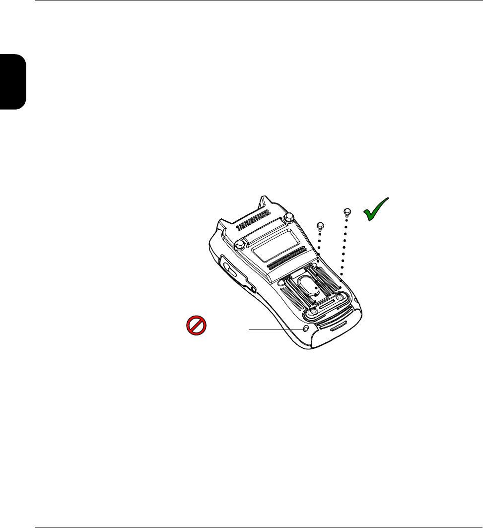
Verizon Base Unit User Guide Rev B PRELIMINARY 3/20/2014 Tech-X Flex® (P5)
1-44
Intro Wi-Fi 10/100 System IP/Video Specs
1.7.1 Battery installation/replacement
A new unit may require the battery to be installed before its first use. Additionally, users may perform field
replacement of the battery pack as necessary. No tools are required. Note the following:
• New battery packs should be ordered from Spirent (MPL# T5411). The use of any other battery
could damage the unit and create a safety hazard for users.
• Batteries contain hazardous contaminants and should be disposed of according to local regulations.
It may be illegal to discard batteries in the general trash.
To replace the battery pack
1. On the back of the unit, remove the two battery pack hand screws at the base of the kickstand. Be
careful not to accidentally remove the unit cover screws which require a screwdriver (see Figure 1-
29).
Figure 1-29 Battery pack screws
2. Gently slide the old battery pack out (with the cradle) from the bottom of the unit and insert the new
battery pack. For new units, the battery chamber may have a placeholder instead which can be
discarded once a battery is installed.
Battery pack
screws
Unit cover
screw

Tech-X Flex® (P5) Verizon Base Unit User Guide Rev B PRELIMINARY 3/20/2014
1-45
Intro
Wi-Fi
10/100
System
IP/Video
Specs
Figure 1-30 Inserting a battery pack
3. Following battery insertion, reinstall the hand screws.
NOTE: Do not overtighten the screws, which could cause the plastic to crack.
1.8 FTP information
The unit has several features that may involve transferring files to and/or from the unit. In most cases,
this transfer is handled by an FTP operation, during which the unit acts as an FTP client, invoking
functions on an external FTP server. Therefore, to complete an FTP exchange, you must have an FTP
server installed, properly configured, and actively running on a computer that is networked to the unit.
This section describes general information associated with FTP server setup. Information about specific
file transfer operations is provided elsewhere in this document as appropriate.
1.8.1 Admin Port setup
Before any FTP action is possible, you must have the Admin Port configured with routable IP
information. This port is effectively the gateway to the “outside world.” For more information, see Admin
Port on page 4-6.

Verizon Base Unit User Guide Rev B PRELIMINARY 3/20/2014 Tech-X Flex® (P5)
1-46
Intro Wi-Fi 10/100 System IP/Video Specs
1.8.2 FTP server installation and setup
Currently, the only extensively tested and approved FTP server is FileZilla, a free, open-source
application available at http://filezilla-project.org/ at the time of this writing. The FileZilla server runs on
the Windows platform only and may run on any Windows computer. Typically, a networked desktop PC is
the best choice to host the server.
The primary tasks involved with server setup are generally performed one time and include:
• Installation of the server software
• The configuration of one or more user accounts for the server, which the unit will use to log in and
transfer files.
To set up FileZilla on a host computer:
1. Download the FileZilla server installation package (not the client).
2. Launch the package and install according to default settings, unless customization is desired. In the
installation wizard, note that the Port option applies to the server management port, not the FTP
listening port. In most cases, the default of 14147 is adequate.
3. Open the server management interface, normally with a new icon on the desktop or perhaps Start >
FileZilla Server > FileZilla Server Interface. If you are running the server on a local computer, the
default Server Address and Port should be correct. For new installs, you can leave the password
blank.
4. In the interface window, select Edit > Users.
5. In the Users window, click Add to add a new FTP user account, which the unit will use to transfer
files to and/or from the computer.
6. In the Add user account window, specify a user name (such as techFLEX_ALL) and click OK. This
user name will be a required entry when the file transfer is initiated on the unit. It is good practice to
set up separate user accounts for each transfer activity required by the unit, such as channel guide
import versus results export.
7. Back in the Users window, under Page, click the General page link and create a password if desired.
Important! The password is optional. If you create one, it will be required when a file transfer is
initiated on the unit.
8. In the Users window, under Page, click the Shared folders page link, then under Shared folders
click Add to specify a home folder for the user account. When an FTP connection is established for
this account, this is the default folder from which files are transferred.
NOTE: Some unit FTP activities involve the transfer of data from the unit to the FTP server, in
which case you should be sure to click the Write checkbox under Files, for the shared folder you
added. By default, new user accounts have writing disabled, which will cause any export function
from the unit to fail.
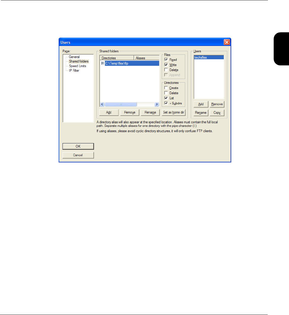
Tech-X Flex® (P5) Verizon Base Unit User Guide Rev B PRELIMINARY 3/20/2014
1-47
Intro
Wi-Fi
10/100
System
IP/Video
Specs
At this point, the user account should be complete. The dialog box should appear something like the
following:
Figure 1-31 Completed user account in FileZilla
9. In the Users window, click OK to save the new user.
10. Back in the management interface, if necessary select Server > Active to ensure that the server is
actively listening for FTP requests.
NOTE: FileZilla includes a variety of configuration options, including whether to automatically launch
and enable the server upon Windows startup. Further information is beyond the scope of this
document. See the FileZilla documentation for more information.
1.8.3 FTP connection parameters
When an FTP-related operation is invoked, the unit requires standard connection parameters to reach
the FTP server and perform the file transfer. These parameters may include:

Verizon Base Unit User Guide Rev B PRELIMINARY 3/20/2014 Tech-X Flex® (P5)
1-48
Intro Wi-Fi 10/100 System IP/Video Specs
Server IP address or domain name of the computer where the FTP server is running. This
computer will be the source for any files transferred to the unit and/or the
destination for any files transferred from it. The specific folder on the computer is
generally determined by the user account configured as described under FTP
server installation and setup on page 1-46 and specified below (User ID).
Port TCP port used by the FTP server, typically 21 (standard FTP port). The server port
can be changed in the server management application - see the server
documentation for more information.
User ID
Password
FTP authentication information, valid for a user account currently configured on
the FTP server. This account will be associated with a folder on the server
computer where files will be transferred to or from. For more information, see FTP
server installation and setup on page 1-46.
Server Folder Subfolder where files should be transferred to or from, relative to the user folder
configured as described under FTP server installation and setup on page 1-46.
This parameter is only applicable to some unit functions and may be optional. If it
remains unspecified or does not appear at all, all files will be transferred to or from
the “home directory” associated with the FTP user account (User ID).
Ping Before
Transfer
Runs a ping test to the server computer before the FTP attempt. If all ping
attempts fail, the FTP attempt is aborted. Not all FTP-related operations support
this parameter.
Admin port
information
FTP transaction screens also normally include information about the Admin Port,
which is the interface through which the FTP transaction will occur. If the FTP
action is a “download” action where a file is transferred to the unit, this information
is normally found in a Destination tab. Otherwise, it is found in a Source tab. In
either case, the screen provides:
• IP information about the currently-established Admin Port, if there is one.
-and-
• Buttons to set up an Admin Port which transport you to the standard Admin
Port setup screen, after which you will be returned to the applicable FTP
screen.
In all cases, you must have an Admin Port configured to complete the FTP
transaction, whether you have configured it beforehand or through the shortcuts in
the FTP area.

Tech-X Flex® (P5) Verizon Base Unit User Guide Rev B PRELIMINARY 3/20/2014
1-49
Intro
Wi-Fi
10/100
System
IP/Video
Specs
1.8.4 FTP connection troubleshooting
Following an FTP attempt, the unit will report whether the action was successful. If the attempt fails,
ensure that:
• You are using an approved FTP server and that it is configured correctly.
• You have specified the FTP input parameters exactly right. A single character mistake in any of them
will cause a connection failure.
• The FTP server computer and the unit have IP-level connectivity. Either device should be able to ping
the other.
• The traffic between the unit and the FTP server is not blocked by a firewall. In particular, if the FTP
server is on a Windows computer, it is not uncommon for the default settings of an active Windows
Firewall to prevent the transfer. When a firewall blocks FTP activity, the server administration
interface will show zero activity while the unit is attempting the transfer, because there is ultimately no
connection between the two entities.
Firewall configuration is beyond the scope of this document. For more information, see the Windows
Firewall documentation, the FTP server documentation, and/or contact an IT administrator.
1.9 Technical support
If you need product assistance or want to report problems with the product or the documentation, please
contact us.
E-mail: support@spirent.com
Phone:
North America 1-800-SPIRENT
China +86 (10) 8233 0033
China mainland only +86 (800) 810-9529
France +33 (1) 6137 2270
UK (EMEA TAC) +44 1803 546333

Verizon Base Unit User Guide Rev B PRELIMINARY 3/20/2014 Tech-X Flex® (P5)
1-50
Intro Wi-Fi 10/100 System IP/Video Specs
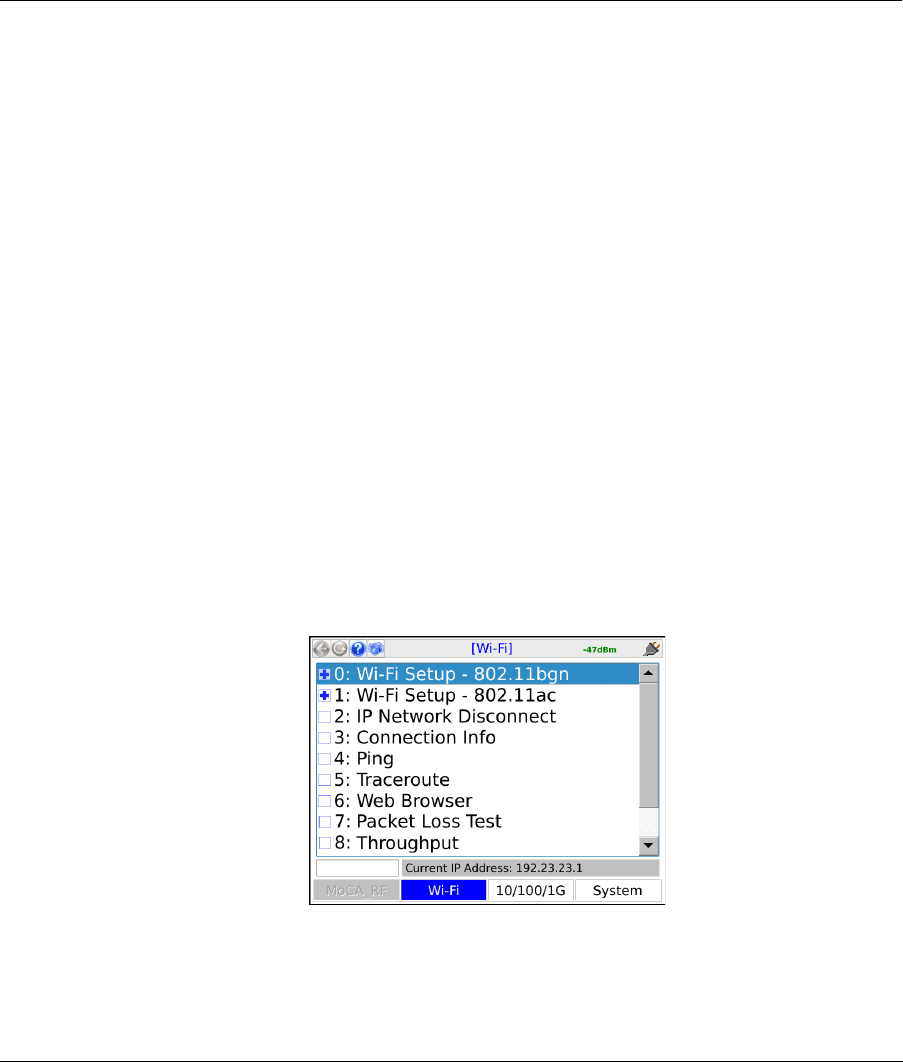
Tech-X Flex® (P5) Verizon Base Unit User Guide Rev B PRELIMINARY 3/20/2014
2-1
2: Wi-Fi Testing Menu
Wi-Fi testing on the unit includes:
• Scanning for available wireless access points
• Connecting to an existing network and obtaining IP information
• Basic network-level testing such as ping, traceroute, and web browsing
All Wi-Fi testing is performed from the Wi-Fi menu. When this menu is active, all testing uses the Wi-FI
interface only. That is, no other interface will process test requests.
NOTE: You must have a Wi-Fi connection established before any other Wi-Fi functions become
available. Furthermore, when you leave the Wi-Fi menu, the Wi-Fi interface is shut down and
the existing connection, if any, is dropped unless you have the unit configured to keep the
interface active.
Figure 2-1 Wi-Fi main menu

Verizon Base Unit User Guide Rev B PRELIMINARY 3/20/2014 Tech-X Flex® (P5)
2-2
Intro Wi-Fi 10/100 System IP/Video Specs
2.1 Important wireless 802.11ac note
When the unit is actively transmitting in 802.11ac mode, the unit should be placed on a horizontal
surface with a minimum distance of 20 cm from any part of a human body. Note that this restriction
only applies when the unit is actively connected to a network, not while scanning for networks. Other
modes (for example, 2.4 GHz 802.11b/g/n) do not involve any such restrictions.
2.2 Functionality note
Wi-Fi connection and testing is a purchasable option. Please contact Spirent for more information.
2.3 Wi-Fi overview
The following sections describe general information about the unit and Wi-Fi.
2.3.1 Wi-Fi support details
The unit supports:
• Connection to IEEE 802.11 standards including b, g, n, and ac.
• Open and secured networks, including:
– Wired Equivalent Privacy (WEP) authentication, both WEP-64 (40-bit key) and WEP-128 (104-bit
key)
– Wi-Fi Protected Access (WPA and WPA2) authentication, using pre-shared key (PSK) mode
NOTE: The unit cannot connect to a network that does not broadcast its SSID. A network such as this
may appear within Scan results; however, the controls related to connection will be disabled.
By emulating a wireless PC in the home, you can perform troubleshooting activities such as:
• Verifying ISP availability and therefore ruling out the provider network as the cause of internet
connectivity problems. If the unit can access the internet but a subscriber PC cannot, it is likely that
the problem resides in the PC and/or its wireless interface.
• Determine whether Wi-Fi “dead zones” exist at the premises and whether they are affecting network
performance. In some cases, wireless network troubles may be caused by equipment that is simply
out-of-range of the source.
Detailed technical information about Wi-Fi and 802.11 is beyond the scope of this document. If you are
having trouble connecting, see If you cannot connect (troubleshooting tips) on page 2-3.
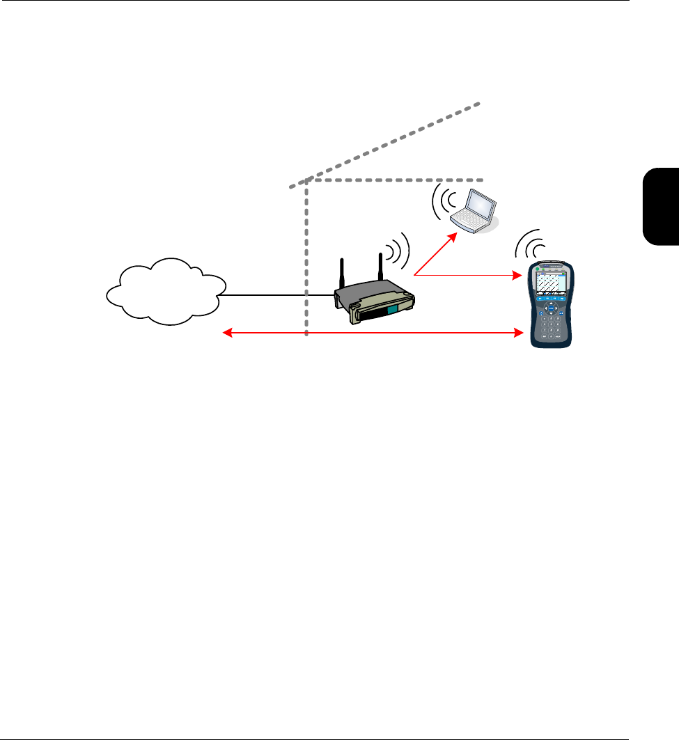
Tech-X Flex® (P5) Verizon Base Unit User Guide Rev B PRELIMINARY 3/20/2014
2-3
Intro
Wi-Fi
10/100
System
IP/Video
Specs
2.3.2 Wi-Fi testing diagram
The following diagram shows a typical setup for Wi-Fi testing.
Figure 2-2 Typical Wi-Fi testing diagram
2.3.3 If you cannot connect (troubleshooting tips)
If you are in range of a wireless access point but cannot connect, verify the following:
• If entering all information manually, you have properly identified the network. Because this is an error-
prone process, it is recommended that you use the auto-scan feature to find the network and
prepopulate many of the parameters (see Wi-Fi Setup > Scan on page 2-4.)
• The network is not an “ad hoc” network, which the unit does not support within the normal Wi-Fi
menu tools.
• You have identified the proper security protocol in use and have the necessary information for
connection. If the network uses WEP or WPA-PSK, you must have the required authentication
information. If it uses a different protocol that the unit does not support, such as WPA-EAP or MAC
address restrictions, you will not be able to connect.
2.4 Wi-Fi Setup
The Wi-Fi Setup - 802.11bgn (802.11b, g, and n) and Wi-Fi Setup - 802.11ac (802.11ac) menus contain
all the functions associated with finding and connecting to Wi-Fi networks, including:
Ping, traceroute, web browsing
Provider
network/ISP
Wireless
router
Home
computer
Ping

Verizon Base Unit User Guide Rev B PRELIMINARY 3/20/2014 Tech-X Flex® (P5)
2-4
Intro Wi-Fi 10/100 System IP/Video Specs
•Wi-Fi Setup > Scan on page 2-4
•Wi-Fi Setup > Connect on page 2-5
•Wi-Fi Setup > Wi-Fi Quick Test on page 2-8
•Wi-Fi Setup > Details on page 2-10
These functions operate generally identically for all wireless protocols.
2.4.1 Wi-Fi Setup > Scan
This function scans for all wireless networks within range of the unit and lists them on the display. Once
the list is produced, you can select the desired network and use the Connect shortcut to connect. This
method of connecting to a wireless network is preferred because:
• You can ensure that you are connecting to the correct network on the correct channel. In densely-
populated areas, it is not unusual for multiple wireless networks to be available within any given
residence, including networks with the same SSID (name).
• When the connection action is initiated, the unit prepopulates many of the parameters which would
otherwise need to be entered manually with potential for error.
• Even if the network is familiar and/or you know all the parameters, the Scan function will verify that it
is actually available.
Once you successfully connect to the network through the Scan function, it is added to the history of
networks where it is available for the manual connection process (see Wi-Fi Setup > Connect on
page 2-5).
Setup - Scan (Wi-Fi Setup)
The Wi-Fi Scan requires no setup parameters. The process launches immediately following the menu
selection.
Results - Scan (Wi-Fi Setup)
The scan lists up to 12 networks within range of the unit, displaying the SSID (name), an icon that
denotes whether the network is secure (WEP, etc.), and other relevant parameters. The scan reruns
periodically and updates the table. For more information on the fields in the table, see the descriptions
under Wi-Fi Setup > Details on page 2-10.
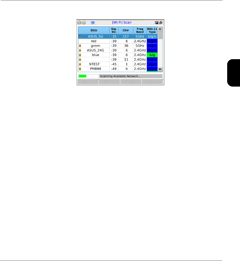
Tech-X Flex® (P5) Verizon Base Unit User Guide Rev B PRELIMINARY 3/20/2014
2-5
Intro
Wi-Fi
10/100
System
IP/Video
Specs
Figure 2-3 Wi-Fi Scan results
Note the following:
• The unit only displays the first 12 networks detected. If more networks are available, they will not
display, even if the unit is currently connected to one of them.
• A network that does not broadcast its SSID will still be listed, but the SSID value will be blank and the
unit will not allow connection to it.
Results screen shortcuts:
•Connect - Launches the Wi-Fi connection function for the selected network (see Wi-Fi Setup >
Connect on page 2-5)
•Details - Displays details of the selected network, similar to those displayed when you request the
details of a currently-connected network (see Wi-Fi Setup > Details on page 2-10)
•Pause/Resume - Stops and starts the continuous scan
•Save - Saves the Scan results (see Record Manager on page 4-1)
2.4.2 Wi-Fi Setup > Connect
The Connect function attempts a connection with a wireless network according to the specified
parameters. If you used the Wi-Fi Setup > Scan function results to launch the Connect, many of the
parameters are automatically populated. For this reason, the Scan function is generally recommended
as a prerequisite.
Once the unit successfully connects, the network parameters are saved in memory under the respective
SSID (name).
NOTE: If you have trouble connecting, see If you cannot connect (troubleshooting tips) on page 2-3.

Verizon Base Unit User Guide Rev B PRELIMINARY 3/20/2014 Tech-X Flex® (P5)
2-6
Intro Wi-Fi 10/100 System IP/Video Specs
Setup - Connect (Wi-Fi Setup)
Table 2-1 Connect (Wi-Fi Setup) - Setup parameters page 1
Parameter Description
SSID (Service Set Identifier) Network name.
Channel Number Network channel, managed automatically by the unit. If the connect request was
initiated from the Scan results screen, it will be populated with the same value from
that screen. Otherwise, it is populated as Auto. In all cases, no user input is
required.
NOTE: Reported channel numbers may deviate from expected values due to
the various methods by which channels are identified. Wi-Fi standards
have concepts of “primary” and “center” channels that represent
different frequencies within the full channel bandwidth. According to their
interpretation of the respective standard, different Wi-Fi devices may
interpret channel numbers differently. A difference between a channel
number configured on another Wi-Fi node and the number reported by
the unit will not affect the ability to connect.
Network Type Type of network:
INFRASTRUCTURE - A centralized network where the unit will negotiate with a
single access point that manages the network overall.
NOTE: Connection to “ad hoc” Wi-Fi networks is currently not supported.
Security Type Type of security in use on the network:
•WEP-64 - Wired Equivalent Privacy using a 40-bit key
•WEP-128 - Wired Equivalent Privacy using a 104-bit key
•WPA-PSK or WPA2-PSK - Wi-Fi Protected Access (WPA or WPA2), pre-shared
key mode
•NONE - No security (open access)

Tech-X Flex® (P5) Verizon Base Unit User Guide Rev B PRELIMINARY 3/20/2014
2-7
Intro
Wi-Fi
10/100
System
IP/Video
Specs
Table 2-2 Connect (Wi-Fi Setup) - Setup parameters page 2
Table 2-3 Connect (Wi-Fi Setup) - Setup parameters page 3
Parameter Description
Key Type and Key Type of key and the key itself, as follows:
•If Key Type=HEX, the Key must be a hexadecimal number. A hex digit
occupies four bits, so for WEP-64, a hex Key must be 10 digits (40 bits total).
For WEP-128, a hex Key must be 26 digits (104 bits total). For WPA-PSK, the
Key must be 64 digits (256 bits total).
•If Key Type=PASSPHRASE, the key must be the appropriate string that can
be converted to the correct key using the respective algorithms. For WEP-64,
a passphrase Key must be 5 characters/digits. For WEP-128, a passphrase
Key must be 13 characters/digits. For WPA-PSK, a passphrase Key must be
8 to 63 characters.
WEP Authentication For WEP only, Type of initial authentication used by the wireless access point:
•OPEN - Effectively no authentication to associate and connect; however, all
communications following the connection will be WEP-encrypted and
therefore the unit must still have the correct key specified.
•SHARED - Requires matching keys to establish the initial connection, which
involves a more detailed handshake transaction between the devices.
Afterwards, all communications are WEP-encrypted similar to open
authentication.
NOTE: This setting does not affect how you specify the Key Type and
Key. It controls how the unit attempts initial negotiations only. Both
OPEN and SHARED WEP require a valid key.
WEP Key Slot For WEP only, the slot associated with the specified Key.
Parameter Description
DHCP After
Connect
Causes the unit to attempt a DHCP-based IP network setup if the connection is
successful. Otherwise, IP network setup will be a separate task following the
connection (see IP Network Setup on page 2-11).
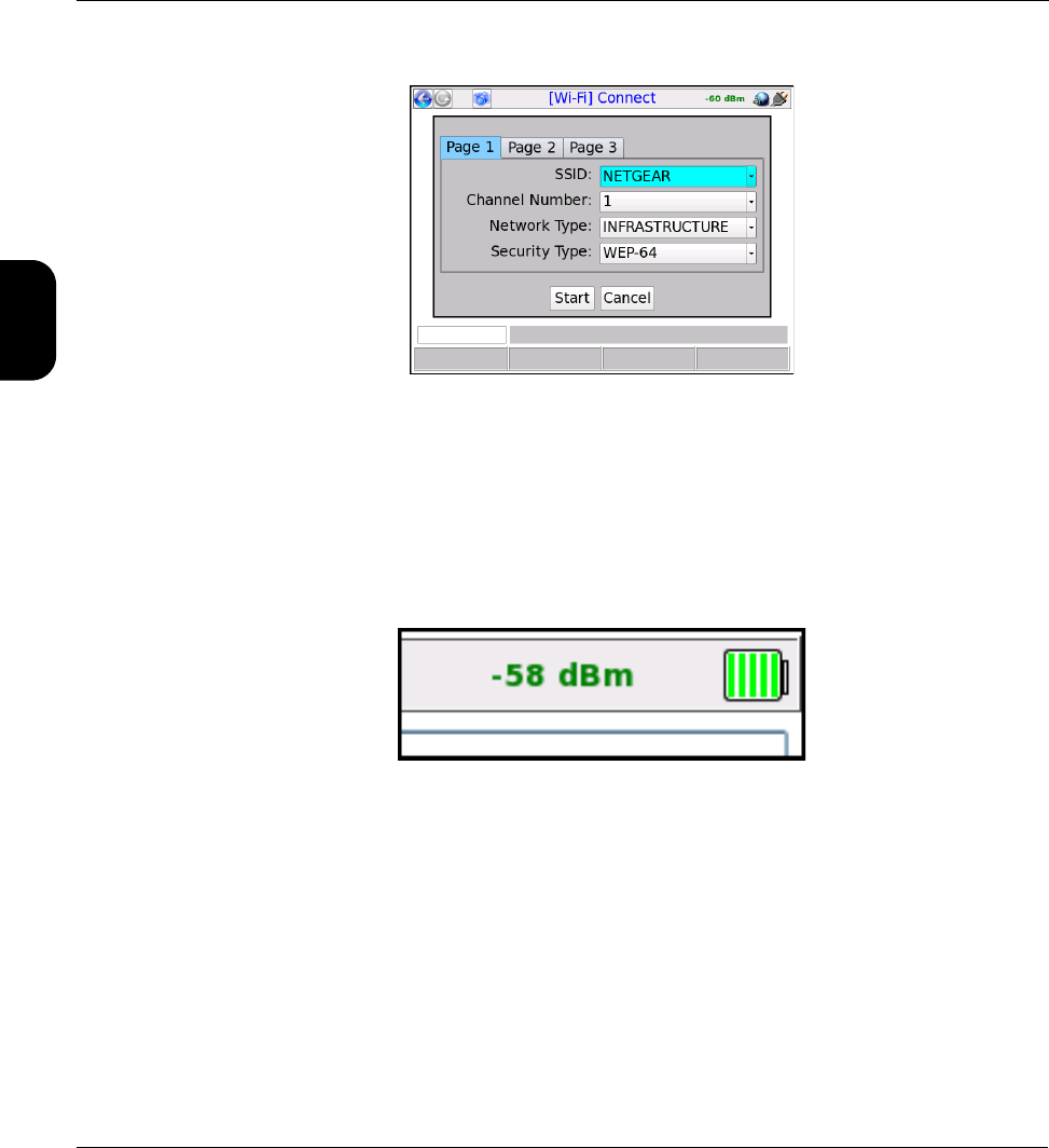
Verizon Base Unit User Guide Rev B PRELIMINARY 3/20/2014 Tech-X Flex® (P5)
2-8
Intro Wi-Fi 10/100 System IP/Video Specs
Figure 2-4 Wi-Fi Connect parameters (Page 1)
Results - Connect (Wi-Fi Setup)
The unit reports whether the connection was successful or not. If the connection is successful, the SYNC
LED lights as solid green. If the connection failed and you don’t know why, see If you cannot connect
(troubleshooting tips) on page 2-3.
While a connection is active, the unit maintains the current signal strength level in the upper right corner:
NOTE: After connection, you must obtain an IP address if you want to do any IP-based testing, if you
did not request an automatic DHCP request in the connection setup. For more information, see
IP Network Setup on page 5-2.
2.4.3 Wi-Fi Setup > Wi-Fi Quick Test
The Wi-Fi test runs a brief set of tests on a wireless network as quick, high-level evaluation. If the unit is
already connected to a network, the Wi-Fi Quick Test runs on that network. Otherwise, the test will
prompt you for the desired network, noting that:

Tech-X Flex® (P5) Verizon Base Unit User Guide Rev B PRELIMINARY 3/20/2014
2-9
Intro
Wi-Fi
10/100
System
IP/Video
Specs
• For wireless B, G, and N networks, the scope of testing does not require a full connection; therefore
only an SSID is required.
• For wireless AC networks, a full connection is required to complete all tests; therefore the full set of
connection parameters are required (see Setup - Connect (Wi-Fi Setup) on page 2-6).
The testing involves the following stages and produces a running status of events in a Log tab:
1. Signal strength and quality measurements (all networks) - The test reports strength and quality
measurements. For more information on these values, see Wi-Fi Setup > Details on page 2-10.
2. Network connection and IP address configuration (Wireless AC only) - If the unit is not currently
connected to the specified network, a connection attempt is made. A valid connection is required to
complete the remainder of the stages. The IP address configuration uses DHCP.
3. Packet Loss Test (Wireless AC only) - The unit runs a standard Packet Loss Test for a duration
specified in the Wi-Fi thresholds area (see System/Module Settings > Wi-Fi > View/Edit Thresholds
on page 4-16). The test automatically targets the default gateway as returned from the DHCP
request, expected to be the residential router or BHR. For general information on the Packet Loss
Test, see Packet Loss Test on page 5-8.
4. Speedtest (Wireless AC only) - The unit runs a standard Speedtest using the destination region
specified in the Wi-Fi thresholds area (see System/Module Settings > Wi-Fi > View/Edit Thresholds
on page 4-16). For general information on the Speedtest, see Speedtest on page 5-13.
5. Summary (all networks) - When the test finishes, it presents a general summary, including an
overall evaluation of the network labeled Wi-Fi network. If any stage has produced a failed result,
the entire test receives an evaluation of FAIL. If any stage has produced a marginal result but no
stages failed, the network receives an evaluation of MARGINAL.
Most of the results produced by the test are evaluated against configured thresholds and
colored/annotated appropriately (see System/Module Settings > Wi-Fi > View/Edit Thresholds on
page 4-16). In the Log tab, stages are marked using colored icons according to thresholds that were
evaluated during the process. A single failed or marginal evaluation causes the respective stage to be
marked as such, with a failure taking precedence. Likewise, individual results in the Details tab are
colored as appropriate. Note that a failure does not mean that the testing process could not complete,
only that a threshold was violated.
NOTE: All results are saved automatically and uploaded whenever an IP connection becomes
available, perhaps as a part of this testing (see About automatic result file upload on page 4-2).
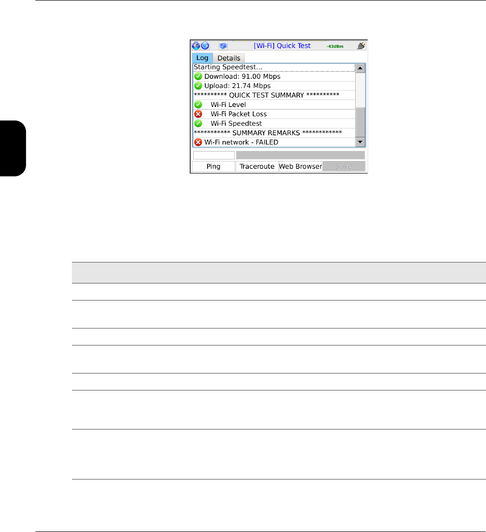
Verizon Base Unit User Guide Rev B PRELIMINARY 3/20/2014 Tech-X Flex® (P5)
2-10
Intro Wi-Fi 10/100 System IP/Video Specs
Figure 2-5 Wi-Fi Quick Test results - Log tab
2.4.4 Wi-Fi Setup > Details
This function reports the details of the currently-active Wi-Fi connection. Results include:
Table 2-4 Details (Wi-Fi Setup) - Results
Result Description
SSID (Service Set Identifier) Network name, as configured in the wireless router.
MAC Address The hardware address of the physical interface at the wireless access point. This
should be a unique identifier of the hardware.
Security Type of security in use by the network.
Security Key The key or passphrase used to authenticate with the network, as specified when
the connection was made.
Signal Strength Signal power level.
Quality Signal quality, as a percentage. This value is reported by the Wi-Fi software and
represents a general assessment only. It does not necessarily provide a
conclusive indication of network bandwidth or reliability.
Channel Number Channel used by the network, typically 1 to 11 with variances possible based on
the country of operation and applicable regulations. A Wi-Fi connection is based
on a single channel which you must have correctly specified when attempting to
connect.

Tech-X Flex® (P5) Verizon Base Unit User Guide Rev B PRELIMINARY 3/20/2014
2-11
Intro
Wi-Fi
10/100
System
IP/Video
Specs
2.5 IP Network Setup
This function allows you to assign IP routing information to the unit in order to perform IP-based testing.
This function operates similarly to other interfaces; however, note that when launched from the Wi-Fi
menu, the assigned IP information applies to the wireless interface/connection only.
After a successful setup, the main menu shows an IP Network Disconnect command which will
terminate the IP network connection. If an IP address was obtained via DHCP, it will be released. This
termination will happen automatically if you navigate away from the Wi-Fi menu.
For more information on parameters and results, see IP Network Setup on page 5-2.
NOTE: The unit must have an active wireless connection before this function is available (see Wi-Fi
Setup on page 2-3).
2.6 Ping
Ping testing over the Wi-Fi interface is similar to other interfaces. For more information, see Ping on
page 5-4.
2.7 Traceroute
Traceroute testing over the Wi-Fi interface is similar to other interfaces. For more information, see
Traceroute on page 5-6.
2.8 Web Browser
NOTE: The Web Browser is a purchasable option. Please contact Spirent for more information.
Use of the Web Browser over the Wi-Fi interface is similar to other interfaces. For more information, see
Web Browser on page 5-7.
2.9 Packet Loss Test
NOTE: The Packet Loss Test is a purchasable option. Please contact Spirent for more information.

Verizon Base Unit User Guide Rev B PRELIMINARY 3/20/2014 Tech-X Flex® (P5)
2-12
Intro Wi-Fi 10/100 System IP/Video Specs
Use of the Packet Loss Test over the Wi-Fi interface is similar to other interfaces. For more information,
see Packet Loss Test on page 5-8.
2.10 Throughput
NOTE: The Throughput test is a purchasable option. Please contact Spirent for more information.
Use of the Throughput test over the Wi-Fi interface is similar to other interfaces. For more information,
see Throughput on page 5-10.
2.11 Speedtest
NOTE: The Speedtest test is a purchasable option. Please contact Spirent for more information.
Use of the Speedtest test over the Wi-Fi interface is similar to other interfaces. For more information, see
Speedtest on page 5-13.

Tech-X Flex® (P5) Verizon Base Unit User Guide Rev B PRELIMINARY 3/20/2014
3-1
3: 10/100/1G Testing Menu
With the 10/100/1G testing menu, the unit is able to join a 10/100/1G Ethernet link and perform the
following functions and tests:
• IP address retrieval/assignment (see IP Network Setup on page 5-2)
• IP ping (see Ping on page 5-4)
• Traceroute (see Traceroute on page 5-6)
• Internet web page request (see Web Browser on page 5-7)
• Packet loss testing (see Packet Loss Test on page 5-8)
• Throughput testing (see Throughput on page 5-10)
• Speedtest testing (see Speedtest on page 5-13)
• IP video testing (see IP Video testing on page 5-15)
• Ethernet bridging and passive testing (see Passive testing on page 3-5)
Figure 3-1 10/100/1G main menu

Verizon Base Unit User Guide Rev B PRELIMINARY 3/20/2014 Tech-X Flex® (P5)
3-2
Intro Wi-Fi 10/100 System IP/Video Specs
NOTE: On the unit, you can use either 10/100/1G port for single-ended tests such as ping and
traceroute. For more information, see About the 10/100/1G ports and connections on page 3-2.
3.1 Functionality note
Your unit may or may not include all the functionality described in this section, dependent upon your
licensing agreement with Spirent. Please contact Spirent for more information.
3.2 About the 10/100/1G ports and connections
The unit has two physical 10/100/1G ports which are connected internally by a functional Ethernet
switch. Therefore, when performing single-ended tests such as ping or traceroute, you may use either
port. When setting up an Ethernet bridge for passive tests, the order of the ports is likewise not important.
NOTE: On the physical port, the unit is able to auto-detect the receive and transmit channels; therefore
you may use straight-through or crossover Ethernet cables for any application.
3.3 10/100/1G testing diagram
The following diagram shows a typical setup for active, single-ended tests. For more information on the
setup for bridged, passive testing, see Passive testing on page 3-5.
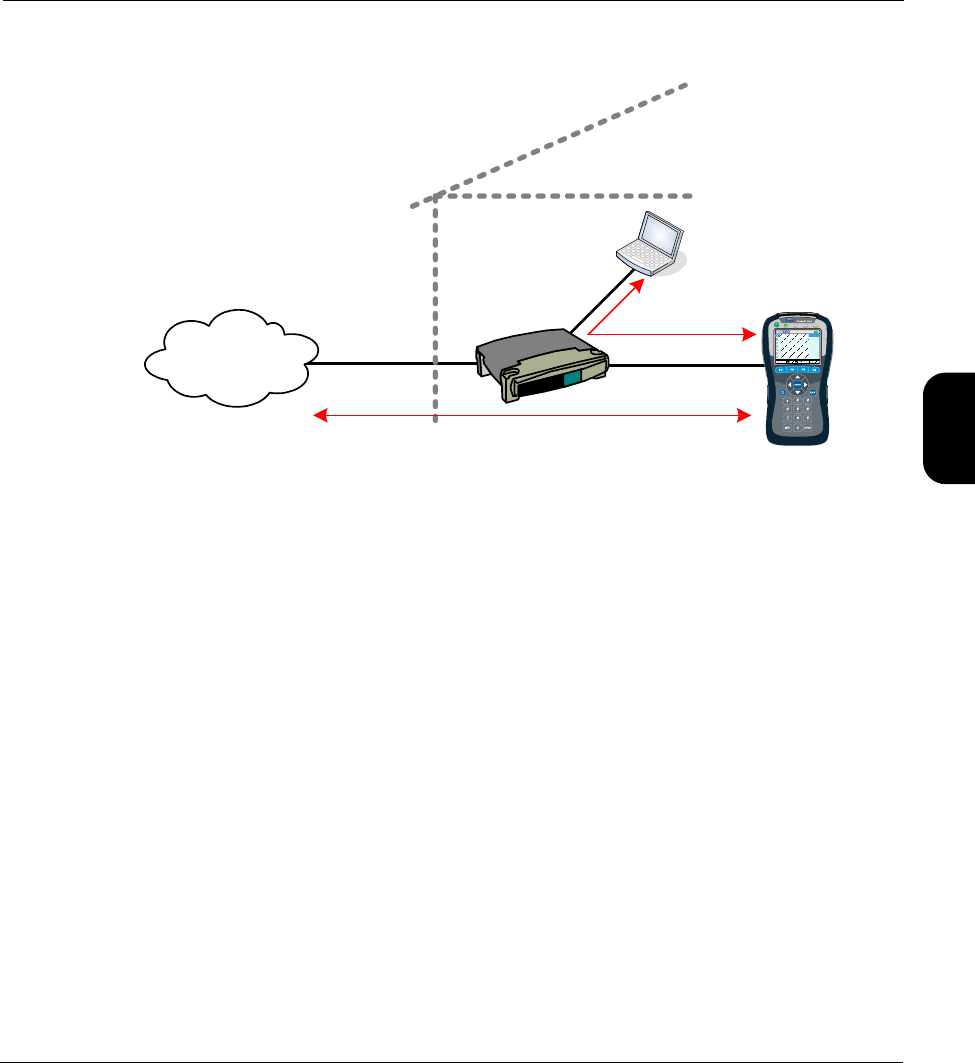
Tech-X Flex® (P5) Verizon Base Unit User Guide Rev B PRELIMINARY 3/20/2014
3-3
Intro
Wi-Fi
10/100
System
IP/Video
Specs
Figure 3-2 Typical 10/100/1G testing diagram
3.4 IP Network Setup
(10/100/1G > IP Network Setup)
This function allows you to assign IP routing information to the unit in order to perform IP-based testing.
This function operates similarly to other interfaces; however, note that when launched from the
10/100/1G menu, the assigned IP information applies to the 10/100/1G interface/connection only.
For more information on parameters and results, see IP Network Setup on page 5-2.
Note the following:
• The unit must be connected to a suitable access device before attempting IP Network Setup (see
10/100/1G testing diagram on page 3-2).
• After a successful setup, the main menu shows an IP Network Disconnect command which will
terminate the IP connection. If an IP address was obtained via DHCP, it will be released. This
termination will happen automatically if you navigate away from the 10/100/1G menu.
3.5 Ping
(10/100/1G > Ping)
Ping, traceroute, web browsing, IPTV video testing
Provider
network/ISP
Home
router
Home
computer
Ping

Verizon Base Unit User Guide Rev B PRELIMINARY 3/20/2014 Tech-X Flex® (P5)
3-4
Intro Wi-Fi 10/100 System IP/Video Specs
Ping testing over the 10/100/1G interface is similar to other interfaces. For more information, see Ping on
page 5-4.
3.6 Traceroute
(10/100/1G > Traceroute)
Traceroute testing over the 10/100/1G interface is similar to other interfaces. For more information, see
Traceroute on page 5-6.
3.7 Web Browser
(10/100/1G > Web Browser)
NOTE: The web browser is a purchasable option. Please contact Spirent for more information.
Use of the web browser over the 10/100/1G interface is similar to other interfaces. For more information,
see Web Browser on page 5-7.
3.8 Packet Loss Test
(10/100/1G > Packet Loss Test)
NOTE: The Packet Loss Test is a purchasable option. Please contact Spirent for more information.
Use of the Packet Loss Test over the 10/100/1G interface is similar to other interfaces. For more
information, see Packet Loss Test on page 5-8.
3.9 Throughput
(10/100/1G > Throughput)
NOTE: The Throughput test is a purchasable option. Please contact Spirent for more information.
Use of the Throughput test over the 10/100/1G interface is similar to other interfaces. For more
information, see Packet Loss Test on page 5-8.

Tech-X Flex® (P5) Verizon Base Unit User Guide Rev B PRELIMINARY 3/20/2014
3-5
Intro
Wi-Fi
10/100
System
IP/Video
Specs
3.10 Speedtest
NOTE: The Speedtest test is a purchasable option. Please contact Spirent for more information.
Use of the Speedtest test over the 10/100/1G interface is similar to other interfaces. For more
information, see Speedtest on page 5-13.
3.11 IP Video Tests
NOTE: Video testing is a purchasable option. Please contact Spirent for more information.
Active IP video testing on the 10/100/1G interface is similar to other interfaces. For more information, see
IP Video testing on page 5-15.
3.12 Passive testing
NOTE: Passive testing is a purchasable option. Please contact Spirent for more information.
Passive testing allows non-intrusive testing on a bridged Ethernet link. The following sections describe
passive testing and bridge setup in more detail.
3.12.1 Unit setup for passive testing
Because the two 10/100/1G ports are joined internally by a functional Ethernet switch, the unit is
inherently capable of bridging an Ethernet link when placed in the middle. With a bridged link, the unit
can passively monitor traffic between the ports (that is, the traffic flowing across the “bridge”), such as
during a passive measurement of video quality. The ports are always active; therefore, the bridge
capability is always active, with the monitoring feature activated when a passive test is run.
With a passive test, the unit does not send any traffic on the link, nor does it interfere with any traffic
passing through the link. However, an active link will be naturally disrupted when the unit is physically
placed in the middle. For a passive test to run, it is required that the desired traffic is activated or restored
between the bridged endpoints before the testing begins. Using the example of passive video testing,
consider the following typical setup:
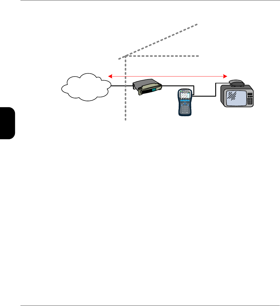
Verizon Base Unit User Guide Rev B PRELIMINARY 3/20/2014 Tech-X Flex® (P5)
3-6
Intro Wi-Fi 10/100 System IP/Video Specs
Figure 3-3 Bridged (passive) video testing
To set up the video test in this example, you should:
1. Connect the physical wires between the endpoints, from router-to-unit and unit-to-STB.
2. Verify that communications between the bridged endpoints are restored. In this example, you should
be able to see the video on the TV.
3. Set up and run the desired test on the unit.
The following notes apply:
• Following successful IP Network Setup, you can also perform single-ended active tests while the link
is bridged, in either direction. In the previous example, you should be able to ping the STB if you
know its IP address, as well as anywhere upstream, including the internet.
• You can use either crossover or straight-through Ethernet cables for any connections to the unit.
3.12.2 Passive Video QoS (Quality of Service)
(10/100/1G > Passive Tests > Unicast Video QoS)
-or-
(10/100/1G > Passive Tests > Multicast Video QoS > Video QoS)
From a quality analysis standpoint, passive video quality testing is generally identical to active testing,
except that instead of actively joining a video stream, the unit monitors an existing stream on a bridged
Active video stream
ISP / IPTV
video service
Router/
gateway
Set-top box
Passive
monitoring
Ethernet

Tech-X Flex® (P5) Verizon Base Unit User Guide Rev B PRELIMINARY 3/20/2014
3-7
Intro
Wi-Fi
10/100
System
IP/Video
Specs
link. Therefore, the video stream must be active between the bridged endpoints before the test can
begin.
For detailed information on the video QoS test parameters and results, see Video QoS (Quality of
Service) on page 5-16.

Verizon Base Unit User Guide Rev B PRELIMINARY 3/20/2014 Tech-X Flex® (P5)
3-8
Intro Wi-Fi 10/100 System IP/Video Specs
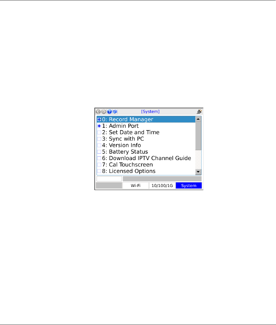
Tech-X Flex® (P5) Verizon Base Unit User Guide Rev B PRELIMINARY 3/20/2014
4-1
4: System Menu
The System menu provides access to general system configuration.
Figure 4-1 System main menu
4.1 Record Manager
(System > Record Manager)
The Record Manager is used to manage, view, and transfer record files, which are special files used to
store test results, screen captures, and other related data. When you invoke the Save function in a
results screen, they are saved to a record file. For non-continuous, self-terminating tests, the full results
set is saved at the end of testing. For continuous tests, you can control when saving is active, during
which time a full results set is saved following the end of each reporting interval.
For test results, at any given time a single record file is considered the active file, which is presented as
the default when you initiate a Save action in a test results screen (see Saving results on page 1-18). If
you have never created any record files, the unit uses a “DEFAULT” record file until you specify

Verizon Base Unit User Guide Rev B PRELIMINARY 3/20/2014 Tech-X Flex® (P5)
4-2
Intro Wi-Fi 10/100 System IP/Video Specs
otherwise. If you do not have the need for multiple record files, the default record may be sufficient for
general use.
For screen capture files, each capture is stored in a separate file that is named at the time of the capture.
For more information, see Capturing a screen image (screenshot) on page 1-17).
NOTE: All files in the Record Manager remain on the unit until purposefully deleted. A unit shutdown
will not delete record data.
The unit has no specific maximum number of record files or maximum amount of results that any record
can contain. However, it does have a certain overall limit related to the constraints of physical memory. A
general rule which might be useful is to have no more than 30 general record files on the unit at once,
each with no more than 20 sets of test results. The actual numbers can vary, though, especially
considering the type of results you are saving. For example, the results data set from a video test is many
times larger than a ping test. Additionally, the presence of screen capture files can reduce the space
available for test results.
NOTE: Verizon units have special functionality related to the automatic upload of results files. For more
information, see About automatic result file upload on page 4-2.
The following sections describe the individual Record Manager functions in more detail:
•Record Manager > Test Result Files on page 4-3 - Provides a viewer for test result files, along with
file management tools
•Record Manager > Signature Cap Files on page 4-5 - Reserved for future use
•Record Manager > Screen Capture Files on page 4-5 - Provides tools to view and/or delete screen
capture files
•Record Manager > Upload Files on page 4-5 - Provides tools for transferring Record Manager files
from the unit to a remote computer, including test result and screen capture files
•Record Manager > Inventory Upload Verizon on page 4-5 - Allows you to upload inventory data to a
Verizon field management system
•Record Manager > Download System Settings on page 4-6 - Allows you to download settings that
control the automatic upload feature for Verizon units
4.1.1 About automatic result file upload
Verizon units are designed to automatically upload certain result files to an internally-configured location,
any time an IP interface is configured by one of the following methods:

Tech-X Flex® (P5) Verizon Base Unit User Guide Rev B PRELIMINARY 3/20/2014
4-3
Intro
Wi-Fi
10/100
System
IP/Video
Specs
• With an Admin Port (see Admin Port on page 4-6).
• Through the Wi-Fi or 10/100/1G testing menu.
• Through an active MoCA synchronization with a MoCA-capable module.
This functionality is designed to facilitate the maintenance of an external field management system that
may be used to track unit inventory and testing results. When the feature is active, the unit immediately
begins the upload of any record files that begin with the following prefix, as soon as an IP interface is
configured:
INVRES
Note the following important aspects regarding this functionality:
• The unit will prohibit any user activity while an upload is in progress. If the unit detects a lack of
progress for a period of time, it will abort the process and try again the next time an IP interface is
configured.
• A file is automatically deleted following a successful upload.
• Files with an INVRES prefix may be viewed on the unit, but cannot be manually deleted.
• Between periods of IP connectivity, files with an INVRES prefix will collect on the unit as testing is
conducted. If the amount of data begins to exceed internal limitations, the unit may start deleting
older files automatically.
• Some tests on the unit automatically save results without user intervention, in which case the
filename will always begin with INVRES and thus qualify the file for automatic upload.
• The location to which files are transferred is fixed internally and cannot be changed, except to
download a new set of “system settings.” These settings include a switch that may be used to disable
the feature entirely. For more information, see Record Manager > Download System Settings on
page 4-6.
•Any Record Manager files that do not begin with INVRES may be managed on the unit with the
standard toolset; however, they cannot be transferred from the unit with FTP. If transfer is desired, a
USB device must be used (see Record Manager > Upload Files on page 4-5).
• All result files include additional important information about the unit and the user. Alternatively, you
can manually invoke the transfer of this data at any time. For more information, see Record Manager
> Inventory Upload Verizon on page 4-5.
4.1.2 Record Manager > Test Result Files
This function allows you to view and manage files currently on the unit. The actions that may be invoked
by the respective function key include:
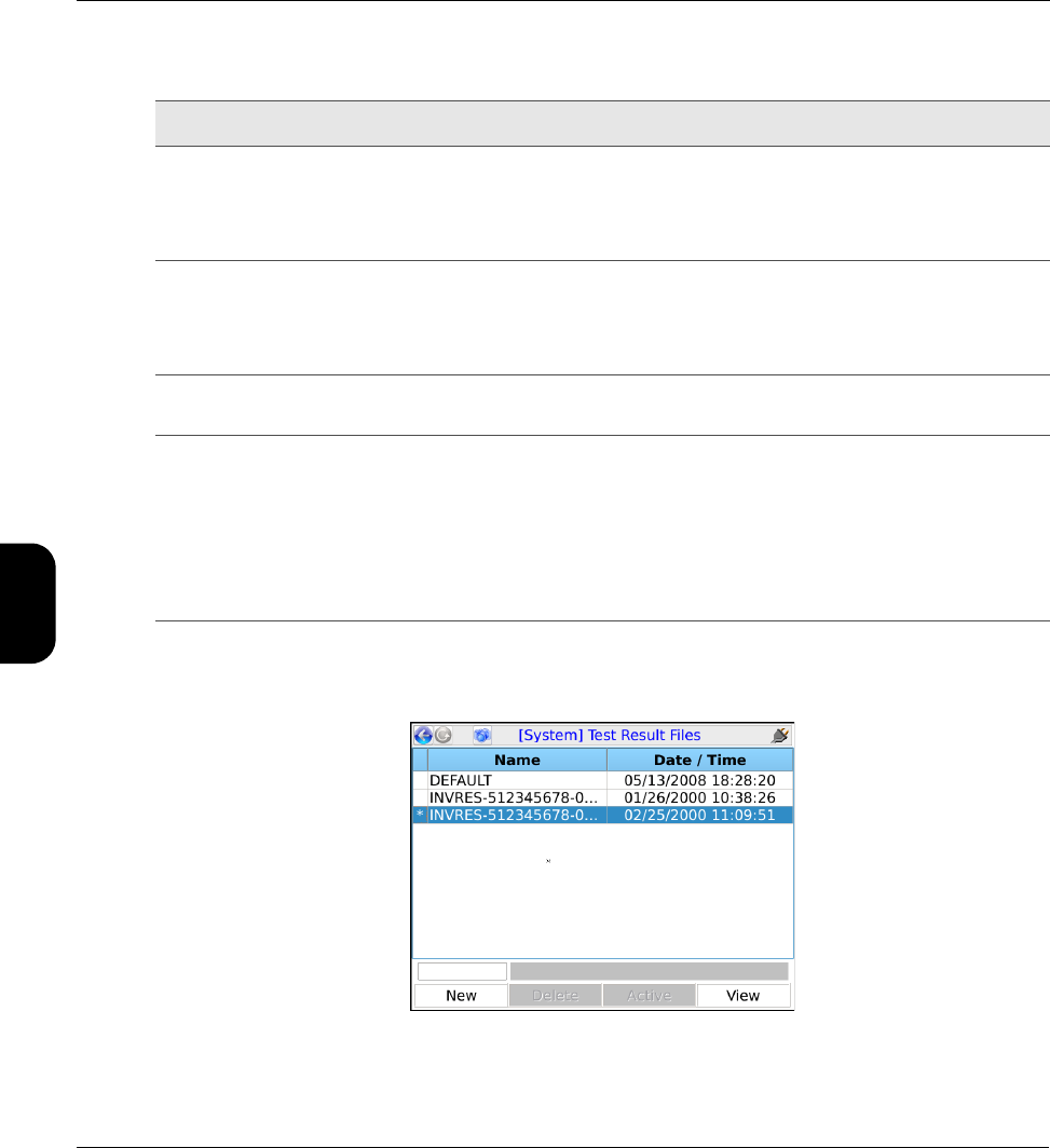
Verizon Base Unit User Guide Rev B PRELIMINARY 3/20/2014 Tech-X Flex® (P5)
4-4
Intro Wi-Fi 10/100 System IP/Video Specs
Table 4-1 Record Manager functions
NOTE: The currently-active file is shown with an asterisk (*) in the left column.
Figure 4-2 Record Manager > Test Result Files
Function Description
New Creates a new record file. The name can have any alphanumeric name, often reflecting a
work order number or a customer location.
NOTE: Do not begin a record name with a period (N1 key), otherwise it will not
appear in the Record Manager.
Delete Deletes the selected file. This action cannot be undone.
NOTE: On Verizon units, files that begin with INVRES are staged for automatic
upload and cannot be manually deleted. For more information, see About
automatic result file upload on page 4-2.
Active Makes the selected file the active file, which then appears as the default when a Save
action is initiated in a test results screen.
View Opens the selected file for viewing in the form of a tree view of results. Normally, a results
set includes one branch with shows details on the original test setup, with a second branch
indicating the success or failure of the operation with additional details as applicable.
NOTE: For some tests, a “mode” parameter appears in the setup area, such as
mode:POLLED and mode:NEXT. The “polled” mode indicates the first interval
of a repeating test and the “next” mode applies to all subsequent intervals of the
respective test. In many cases, this parameter can be simply ignored.

Tech-X Flex® (P5) Verizon Base Unit User Guide Rev B PRELIMINARY 3/20/2014
4-5
Intro
Wi-Fi
10/100
System
IP/Video
Specs
4.1.3 Record Manager > Signature Cap Files
Reserved for future use.
4.1.4 Record Manager > Screen Capture Files
This area allows you to preview and/or delete screen capture files currently stored in the Record
Manager (see Capturing a screen image (screenshot) on page 1-17). To transfer files from the unit, you
must use a USB device (see Record Manager > Upload Files on page 4-5).
4.1.5 Record Manager > Upload Files
This function allows you to transfer record files from the unit to a remote computer, using one of the
following:
•FTP - Not permitted on Verizon devices. Other than automatic uploads, all transfers from the unit
must use a USB device.
•USB - Using the physical USB port on the unit, allows the files to be transferred to a USB storage
device such as a removable flash drive, then transferred from that device to a computer.
NOTE: Do not plug the unit directly into a computer.
At the bottom of the screen, the Start button initiates the transfer. The following table describes the
parameters in the screen:
Table 4-2 Record Manager > Upload Files parameters
4.1.6 Record Manager > Inventory Upload Verizon
This function automatically generates a result file with user and inventory information only, then
automatically uploads it. An active Admin Port is required (see Admin Port on page 4-6). Note the
following:
Tab Description
Files tab Used to select the specific files that should be transferred and whether they should be
deleted from the unit following a successful transfer. Note that the list in this area
includes both test result files and screen capture files, as applicable.

Verizon Base Unit User Guide Rev B PRELIMINARY 3/20/2014 Tech-X Flex® (P5)
4-6
Intro Wi-Fi 10/100 System IP/Video Specs
• This function is part of the automatic file upload feature for Verizon units. For more information, see
About automatic result file upload on page 4-2.
• The same user and inventory data is included with every normal result file as well. This function is
reserved for special cases where this data is required by the server before a result file may be ready
for upload.
4.1.7 Record Manager > Download System Settings
This function allows the download of a configuration file that controls the following settings, related to the
Verizon automatic file upload feature (see About automatic result file upload on page 4-2):
• The location to which result files are automatically uploaded.
• Credentials for the upload, such as FTP/SFTP login information.
• Whether the automatic upload feature is enabled at all.
This function is designed to provide some configuration control over the automatic upload feature,
without exposing the settings to direct manipulation. A standard Admin Port is required and the setup
screen will provide the options to configure it if necessary. Note that:
• Settings cannot be altered during or after the download.
• If the server where the configuration file resides is hosted by Spirent, please contact Spirent for
assistance with an update.
4.2 Admin Port
(System > Admin Port)
This function assigns IP data to the internal management interface of the unit, a prerequisite connection
step for management activities such as firmware upgrades and other actions requiring an FTP exchange.
In this document, all activities that require an Admin Port connection are specifically indicated as such.
Note that this function does not provide general access to the operating system of the unit.
The Admin Port can be connected via two different interfaces, the choice of which is shown in the initial
Admin Port screen:
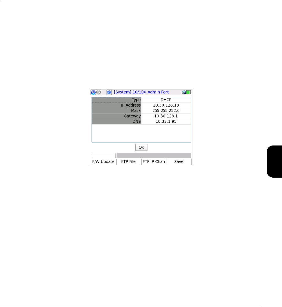
Tech-X Flex® (P5) Verizon Base Unit User Guide Rev B PRELIMINARY 3/20/2014
4-7
Intro
Wi-Fi
10/100
System
IP/Video
Specs
•10/100/1G Admin Port - Initiates a connection through the 10/100/1G Ethernet interface. Either
physical 10/100/1G connector may be used. Once in this area, the process of establishing a
connection is very similar to establishing a 10/100/1G connection for testing purposes with the
10/100/1G menu. For more information on behavior and parameters, see IP Network Setup on
page 3-3.
•Wi-Fi Admin Port - Initiates a connection through the Wi-Fi interface. Once in this area, the process
of establishing a connection is very similar to establishing a Wi-Fi connection for testing purposes
with the Wi-Fi menu. Note that all considerations and limitations involved with a test-related Wi-Fi
connection also apply to the Wi-Fi Admin Port. For more information on behavior and parameters,
see Wi-Fi Setup on page 2-3.
Figure 4-3 Admin Port results screen following a successful connection
Additionally, this area includes two additional commands related to remote control of the unit (see
Remote control of the unit on page 1-19):
•System > Admin Port > WAN Remote Control - See Remote site remote control (via the internet)
setup on page 1-33.
•System > Admin Port > Wi-Fi Admin Port > Ad-Hoc Remote Control - See Local remote control
(via ad hoc Wi-Fi) setup on page 1-31.
Upon a successful Admin Port connection, the results screen includes shortcuts to the following:
•F/W Update (Firmware update - see Update Firmware on page 4-11)
•FTP File (Record manager file upload - see Record Manager > Upload Files on page 4-5)
•FTP IP Chan (IPTV channel guide download - see Download IPTV Channel Guide on page 4-9)
In all cases, when a shortcut is launched, any applicable information from the Admin Port configuration
is automatically transferred to the respective setup screen.
Note the following important items:
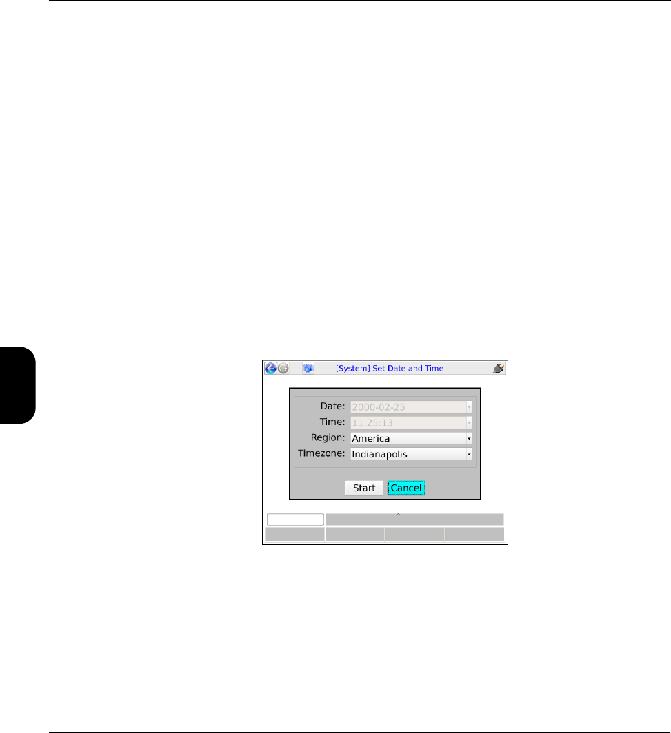
Verizon Base Unit User Guide Rev B PRELIMINARY 3/20/2014 Tech-X Flex® (P5)
4-8
Intro Wi-Fi 10/100 System IP/Video Specs
• In some situations, an active Admin Port may conflict with Ethernet/IP traffic on other interfaces,
especially if multiple interfaces are attempting to host traffic on the same subnet. For example, if you
are attempting to host IP traffic over a MoCA interface while you have an active 10/100/1G Admin
Port with the same router, issues may occur depending on the type of router. If any particular
scenario exhibits trouble, please contact Spirent for a feasibility analysis.
• An active 10/100/1G Admin Port is known to prevent proper functionality of the Bridge (ECB) mode
feature of the MoCA Module.
• An active Admin Port is known to prevent proper functionality of the Router Replacement feature of
the ADSL/VDSL2 Modem Module.
4.3 Set Date and Time
(System > Set Date and Time)
The date and time are used to timestamp all saved results in the Record Manager. They are also used
for various internal functions, described in this document elsewhere as appropriate. Note that on Verizon
units, the date and time are automatically retrieved from the internet whenever a connection becomes
available. They cannot be manually configured.
Figure 4-4 Set Date and Time screen
4.4 Sync with PC
Reserved for future use.
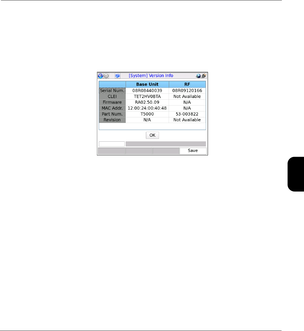
Tech-X Flex® (P5) Verizon Base Unit User Guide Rev B PRELIMINARY 3/20/2014
4-9
Intro
Wi-Fi
10/100
System
IP/Video
Specs
4.5 Version Info
(System > Version Info)
This function provides information about hardware and firmware versions currently applicable to the unit,
including the attached module, if any. This information may be required when obtaining technical support
from Spirent. It may also be useful for verification before and/or after firmware upgrades.
Figure 4-5 Version Info
4.6 Battery Status
(System > Battery Status)
This function provides detailed information about the battery and current charging conditions.
4.7 Download IPTV Channel Guide
(System > Download IPTV Channel Guide)
This function is used to transfer video testing channel guide files to the unit using FTP. To transfer files,
you must have:
• A supported FTP server running on a networked computer. For more information, see FTP server
installation and setup on page 1-46.
• The channel guide files in a folder on that networked computer in the proper location (see File
preparation and general handling notes on page 4-10).
• The unit connected to a 10/100/1G Ethernet network that can reach the FTP server computer.

Verizon Base Unit User Guide Rev B PRELIMINARY 3/20/2014 Tech-X Flex® (P5)
4-10
Intro Wi-Fi 10/100 System IP/Video Specs
Once these steps are complete, the download may be initiated. For more information, see Download
procedure on page 4-10. For general information about channel guide functionality, see About channel
guides on page 5-45.
NOTE: A working knowledge of FTP is helpful for server setup and successful file transfer.
4.7.1 File preparation and general handling notes
• Every transfer action deletes all existing channel guides from the unit, even if the server folder does
not contain any valid files to replace them.
• On the FTP server computer, the files to transfer must be placed in the “home directory” associated
with the FTP user account that you intend to use. For any given transfer action, only the files in a
single folder are transferred to the unit.
• Channel guides must be in the proper XML format as described under About channel guides on
page 5-45.
• All files with an *.xml extension (case-insensitive) are transferred. Any other files in the designated
folder are ignored.
NOTE: If a file named thresholds.xml exists (case-insensitive), it will also be ignored. For this
reason, a channel guide file cannot use this name.
• Other than general limitations of internal disk space, the unit has no functional limitation on how many
channel guide files it may contain.
4.7.2 Download procedure
1. Connect the unit to a 10/100/1G Ethernet network that can access the computer running the FTP
server.
2. Select System > Download Channel Guide and specify the required parameters for download. If
you do not have a Admin Port currently set up, these parameters information must include Admin
Port configuration information. For more information, see FTP connection parameters on page 1-47.
4.8 Cal Touchscreen
(System > Cal Touchscreen)
This function calibrates the touchscreen display for optimal response. Calibration should be done after
firmware upgrades, after battery replacement, or if the screen response begins to degrade after heavy
use.

Tech-X Flex® (P5) Verizon Base Unit User Guide Rev B PRELIMINARY 3/20/2014
4-11
Intro
Wi-Fi
10/100
System
IP/Video
Specs
The process requires you to touch the screen in several places with a stylus or other approved device.
Follow the instructions on the screen.
4.9 Licensed Options
(System > Licensed Options)
This function reports which optional features are currently enabled for the base unit and modules (if any),
which may be required when seeking technical support. It also allows you to manually enable features by
entering valid key codes, which is may be required to enable licensed features on a new unit. To enter a
key code, press Update Key (F1) and enter the key exactly as provided by Spirent. Note the following:
• For more information on what the individual licenses do, see Licensed feature details on page 1-40.
• Firmware upgrades include a provision to automatically apply licensing codes if properly configured
in a file and located on the server from which the firmware is retrieved. For more information, see
Update Firmware on page 4-11.
• The unit requires a unique key code for each licensed feature. For example, to enable both the web
browser and IP video testing, you need to enter two different codes.
• For manual code entry, you do not need to enter anything except the code itself. The unit will
recognize the feature to which it applies and then list that feature as enabled.
• A key code is specific to a unit and will not work on any other unit.
• Key codes must be provided by Spirent. In some cases, the codes required for your licensed feature
set are shipped in the package with the unit. If you have trouble with the codes or require new codes
for any reason, please contact Spirent.
4.10 Update Firmware
(System > Update Firmware)
This function initiates the unit firmware upgrade process. The firmware package must reside on a remote
computer with a properly-configured rsync server running and with IP-level connectivity to the unit.
Spirent hosts one such rsync server which may be available for your use, dependent upon your
arrangement with Spirent and preferences as an organization. Alternatively, you may set up your own
server for private, internal use. The remaining information in this section (including Table 4-3, Update
Firmware parameters on page 4-12) assumes the use of the Spirent-hosted server. For more information
on setting up your own server, please contact Spirent for additional documentation.
Before an update may be initiated, you must configure an Admin Port with connectivity to the rsync
server (see Admin Port on page 4-6). Additionally, note the following:

Verizon Base Unit User Guide Rev B PRELIMINARY 3/20/2014 Tech-X Flex® (P5)
4-12
Intro Wi-Fi 10/100 System IP/Video Specs
• The unit should not be powered down or lose network connectivity during the update process. For
this reason:
–The use of a 10/100 (versus Wi-Fi) Admin Port is recommended. If you do use a Wi-Fi
connection, it is highly recommended that you connect with Wireless G or higher, as Wireless B
may not be stable enough to reliably handle the volume of firmware data.
– The unit requires external power to be connected before allowing an update.
If an update is interrupted, in most cases you should be able to restart the unit and at least
attempt the update again. However, there is a very short window during the process when an
interruption will render the unit unusable and require it to be returned for repair. For this
reason, all precautions against an interruption are highly recommended.
• Firmware may be updated at any time, especially if you are using the Spirent-hosted server. Regular
updates help ensure that your unit is performing at its peak capacity. Note that you can view the
current firmware version on the unit with the Version Info function (see Version Info on page 4-9).
• You do not need to connect a specific module or any module at all to run a firmware upgrade. All
firmware is installed on the base unit, which then transfers it to modules as necessary. If a
disconnected module component is affected by an upgrade (such as the ADSL/VDSL2 module
modem, which has its own firmware), the unit will warn you and then proceed to upgrade that
component when the module is reconnected.
The Update Firmware setup screen includes the following parameters:
NOTE: The middle column indicates the values to use if you are updating from the Spirent-hosted
server. All values should be considered case-sensitive.
Table 4-3 Update Firmware parameters
Parameter Value to use for the
Spirent-hosted server Additional description
Server SPIRENT If you are not using the Spirent-hosted server, this must be
the IP address or domain name of the computer where the
rsync server and firmware files reside. The unit is
provisioned to recognize the SPIRENT keyword to
automatically reach the Spirent server.
Firmware verizon This is an alias that designates the desired firmware
package to install, normally verizon when using the
Spirent-hosted server unless you have been instructed
otherwise. Aliases must be preconfigured on the server
computer in a specific fashion, which is a topic addressed
in the additional documentation available for custom rsync
server setup.

Tech-X Flex® (P5) Verizon Base Unit User Guide Rev B PRELIMINARY 3/20/2014
4-13
Intro
Wi-Fi
10/100
System
IP/Video
Specs
License File TXH_LICENSE_KEYS The name of the file on the server that contains licensing
information for the unit you are upgrading. Licensing is
always updated during the upgrade process unless one or
more of the following are true, in which case licensing
remains in its original state:
• The file is missing or set up incorrectly
• The unit cannot find its licensing information in the file
For custom rsync server setup, additional documentation
from Spirent is available on the management of this file.
Update
License Only
No This setting specifies whether to do a licensing update
only and skip the firmware upgrade. In most cases, the
two are done concurrently.
Ping Before
Download
Yes (recommended) Indicates whether to perform a ping test to the designated
Server before attempting the upgrade. If the ping fails, the
upgrade action will abort.
Timeout 15 Indicates a maximum amount of time to allow for the
upgrade process, after which it is aborted. An aborted
process leaves the unit in its original functional state.
User
Password
(leave blank) Authentication information for the rsync server, configured
when the server is set up. The Spirent-hosted server does
not require authentication.
Parameter Value to use for the
Spirent-hosted server Additional description
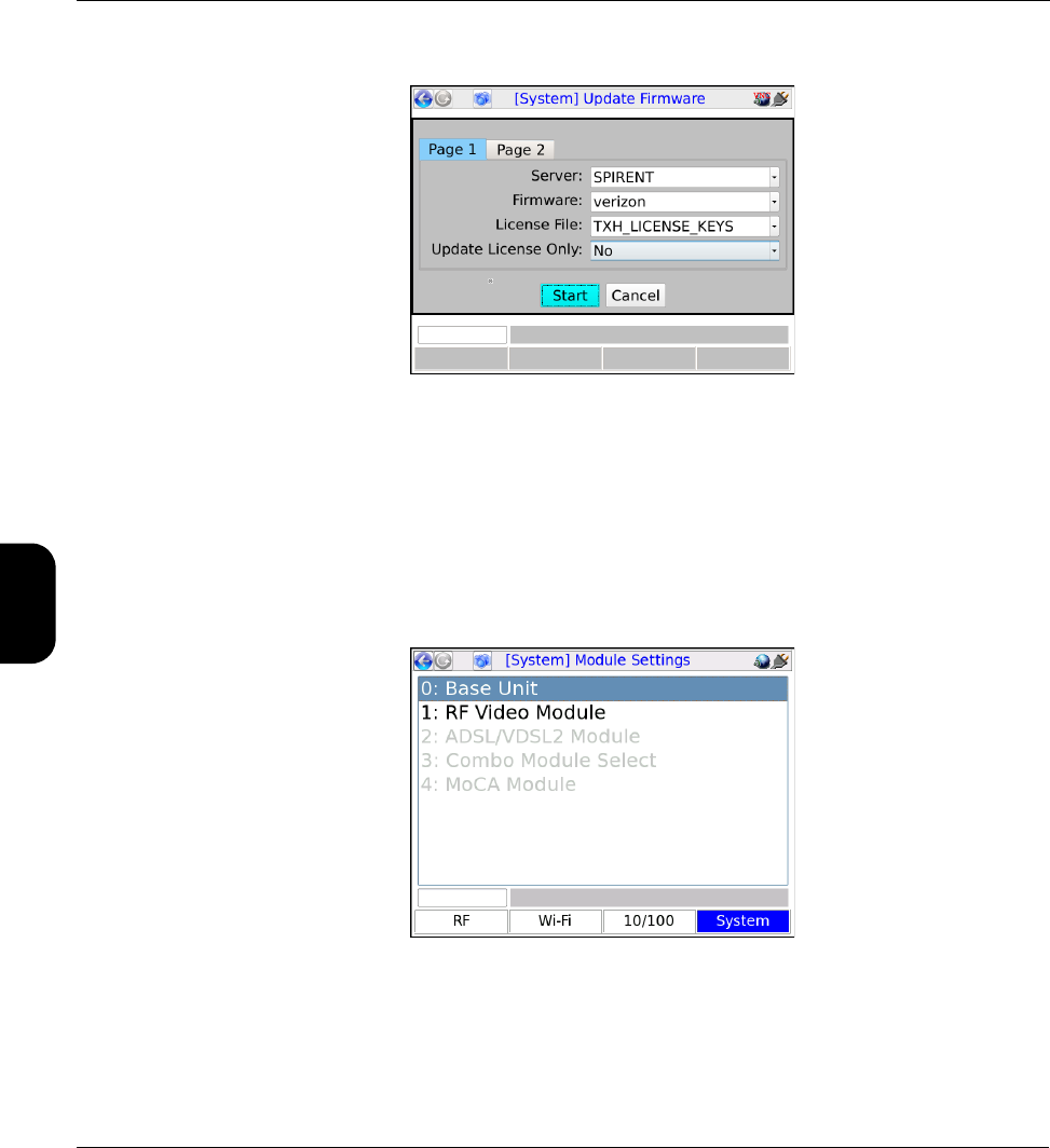
Verizon Base Unit User Guide Rev B PRELIMINARY 3/20/2014 Tech-X Flex® (P5)
4-14
Intro Wi-Fi 10/100 System IP/Video Specs
Figure 4-6 Setup for use of the Spirent-hosted server
4.11 System/Module Settings
(System > System/Module Settings)
This function is used to configure the base unit and/or the attached module and its behavior varies
according to the type of module attached, if any. This section describes the base unit parameters only.
For more information on module settings, see the respective module documentation.
Figure 4-7 Module Settings menu

Tech-X Flex® (P5) Verizon Base Unit User Guide Rev B PRELIMINARY 3/20/2014
4-15
Intro
Wi-Fi
10/100
System
IP/Video
Specs
4.11.1 System/Module Settings > Base Unit
Table 4-4 Base Unit settings
4.11.2 System/Module Settings > RF Video Module
See the RF Module User Guide.
4.11.3 System/Module Settings > ADSL/VDSL2 Module
See the ADSL/VDSL2 Modem Module User Guide.
4.11.4 System/Module Settings > Combined Module Default
Reserved for future use.
4.11.5 System/Module Settings > MoCA Module
See the MoCA Module User Guide.
4.11.6 System/Module Settings > DOCSIS Module
See the DOCSIS Module User Guide.
Tab Description
Auto Sleep
Mode
Sets the maximum amount of idle time after which the unit automatically enters “sleep
mode” in order to save battery power. This setting has no effect when the unit is
powered by an external source. For more information on sleep mode, see Powering
on/off and sleep mode on page 1-10.
Primary
Keyboard
Selects the default keypad that appears when text entry is initiated. For more
information, see Running a function or test on page 1-13.
Asset
Number
Asset identifier for unit inventory control purposes. This value is included in all results
files uploaded from the unit. Otherwise, it has no effect on unit functionality.
This value is preconfigured from the factory and cannot be changed.
Enterprise ID An organization-specific identifier, included in all results files. It may be used to identify
the technician assigned to the unit.

Verizon Base Unit User Guide Rev B PRELIMINARY 3/20/2014 Tech-X Flex® (P5)
4-16
Intro Wi-Fi 10/100 System IP/Video Specs
4.11.7 System/Module Settings > CSM Module
See the Cable Services Module User Guide.
4.11.8 System/Module Settings > MoCA-RF Module
See the MoCA-RF Module User Guide.
4.11.9 System/Module Settings > Wi-Fi
This area includes settings related to the Wi-Fi interface (see Wi-Fi Testing Menu on page 2-1).
System/Module Settings > Wi-Fi > View/Edit Thresholds
This screen allows you to view values that affect the coloring/shading of results for the Wi-Fi Quick Test
(see Wi-Fi Setup > Wi-Fi Quick Test on page 2-8). Thresholds are specified as ranges, such as “Pass”
ranges and “Fail” ranges. For coloring and evaluations related to thresholds, the unit uses:
•Red/Fail for a metric that falls within the “Fail” range
-or-
If the respective threshold does not include a “Fail” range, a metric that falls outside the “Pass” range
•Yellow/Marginal for a metric that falls within a “Marginal” range, if the respective threshold includes
such a range
•Green/Pass (or no coloring) for a metric that falls within the “Pass” range
Additionally, note the following:
• On Verizon units, thresholds cannot be edited with this screen. Any threshold change requires a file
download. For more information, see System/Module Settings > Wi-Fi > Download Thresholds on
page 4-17.
• When specifying thresholds, the unit enforces theoretical/technical limitations. For example, a
percentage cannot be less than zero or greater than 100. In general, if the inherent lower or upper
range of a threshold represents a technical limit, the unit restricts the editing of the field altogether.
• For thresholds with pass, marginal, and fail ranges, the unit enforces continuity between the ranges,
normally by disallowing the editing of certain fields. For example, a marginal Signal Strength range
is automatically determined by the lower Pass and upper Fail values and is therefore restricted from
editing.
•In the Enabled column, you can disable any specific threshold which causes the threshold to have no
effect on coloring or pass/fail evaluations. This feature may be useful for situations where testing with
the unit is required but a final determination of appropriate pass/fail criteria has not yet been made.
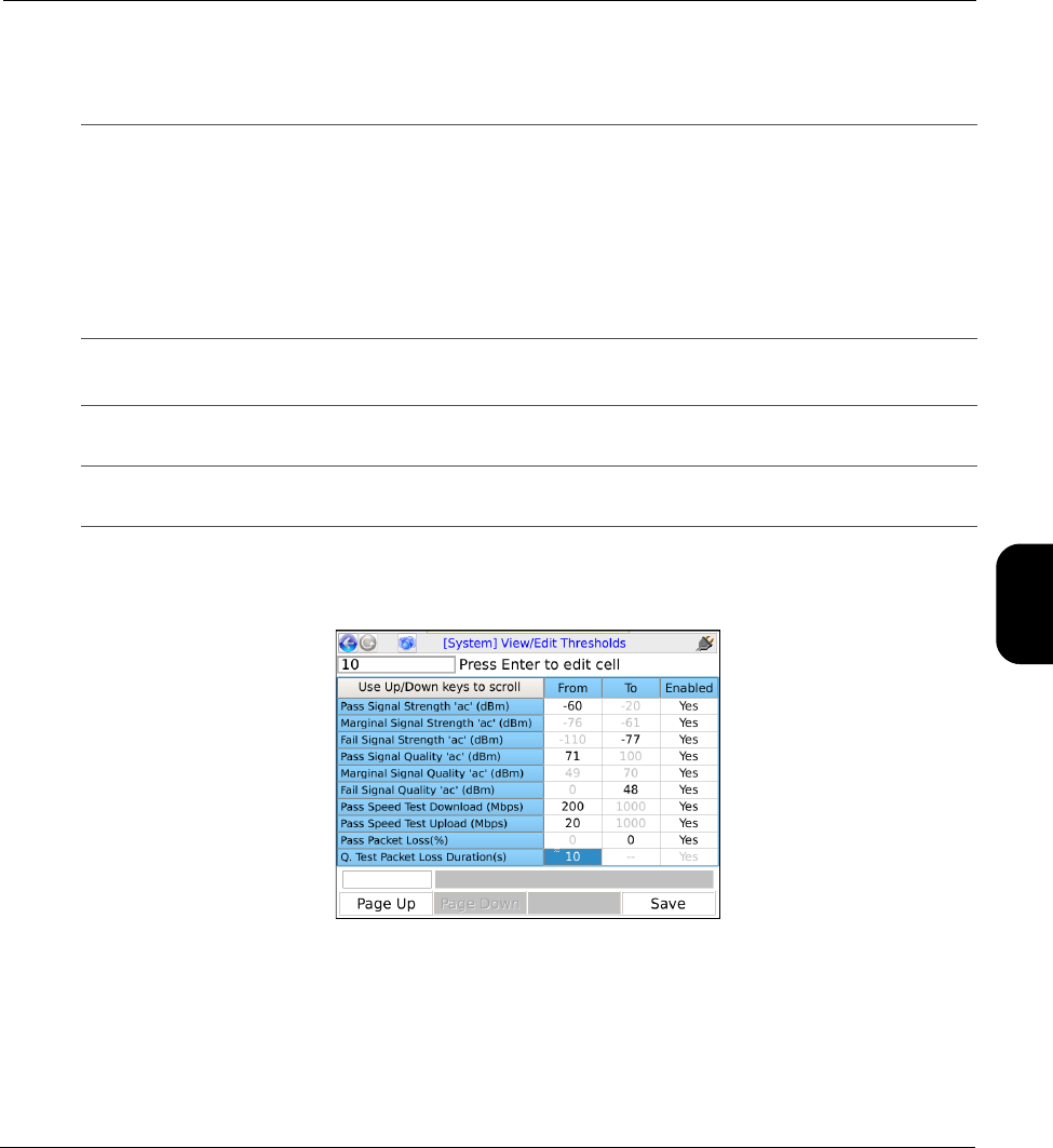
Tech-X Flex® (P5) Verizon Base Unit User Guide Rev B PRELIMINARY 3/20/2014
4-17
Intro
Wi-Fi
10/100
System
IP/Video
Specs
The following table describes the supported thresholds.
As an example, with the following setup, a Signal Strength value for a wireless B network would be
colored yellow if it were between -76 and -71 dB, and red if it were any lower:
Figure 4-8 View/Edit Thresholds screen
System/Module Settings > Wi-Fi > Download Thresholds
As an alternative to editing thresholds directly on the unit, you can download a thresholds file to set all
thresholds as a batch. This action completely overwrites all existing thresholds on the unit.
Signal Strength and Signal
Quality thresholds
Valid ranges for Signal Strength and Signal Quality results, with
independent thresholds for wireless B, G, and N networks versus
wireless AC. With these thresholds, note that:
• Theoretical minimums and maximums are applicable to these
results and therefore the corresponding values are not editable for
these thresholds.
• Marginal thresholds are calculated automatically based on pass/fail
ranges and therefore cannot be edited.
Pass Speed Test Download
Pass Speed Test Upload
Passing ranges for the Speedtest stage of the Wi-Fi Quick Test, for
both the download and upload directions, in Mbps.
Pass Packet Loss Passing ranges for the Packet Loss Test stage of the Wi-Fi Quick
Test, in percent.
Q. Test Packet Loss Duration Duration of the Packet Loss Test stage of the Wi-Fi Quick Test, in
seconds.

Verizon Base Unit User Guide Rev B PRELIMINARY 3/20/2014 Tech-X Flex® (P5)
4-18
Intro Wi-Fi 10/100 System IP/Video Specs
For more information on the parameters required for the FTP transaction, see FTP parameters and
troubleshooting tips on page 1-10. The remainder of this section describes the required threshold file
format.
A threshold file uses a simple CSV format with lines in the following format:
thld_name,from_value,to_value,enabled
For example:
Pass Signal Strength 'bgn' (dBm),-76,--,Yes
It must have the following filename:
WiFiThresholds.dat
Note the following:
• The best way to prepare a threshold file is to start with a working sample. Contact Spirent to obtain a
sample.
• You should never change a threshold name (first field), otherwise the threshold will become
unrecognizable and the unit will use a default instead.
• If any value exceeds a theoretical limitation, the unit will reset it to a valid value. For example, if a
percentage value exceeds 100, it will be reset to 100 upon import. For fields that inherently require a
theoretical maximum, you can specify two hyphens (--) instead of an explicit value.
• You can precede any line with an exclamation point (!) to restrict the setting from editing onboard the
unit, for example:
!Pass Signal Strength 'bgn' (dBm),-76,--,Yes
In this case, the threshold range will be viewable on the unit, but will not be editable. Note that this
condition cannot be undone except by importing another thresholds file to the unit.
NOTE: Verizon units automatically add this character upon file download if not originally specified.
Therefore, thresholds are never editable on the unit itself.
System/Module Settings > Wi-Fi > Quick Test Region
This screen specifies the region to use for the Speedtest stage of the Wi-Fi Quick Test. For more
information, see Wi-Fi Setup > Wi-Fi Quick Test on page 2-8.
4.12 Taskforce
Reserved for future use.

Tech-X Flex® (P5) Verizon Base Unit User Guide Rev B PRELIMINARY 3/20/2014
4-19
Intro
Wi-Fi
10/100
System
IP/Video
Specs
4.13 Signature Capture
This feature allows you to capture a signature using the unit touchscreen. It is generally reserved for
future use.
NOTE: This feature will not function correctly when operating the unit over remote control, even if the
remote device has a touchscreen.
4.14 Language Selection
This function allows you to set the language used by the unit. Note the following:
• Language support is limited. Please contact Spirent for more information.
• On the unit, a language is represented by a special file that contains all the strings associated with
that language. Optionally, you can download another language file to the unit, either to add a new
language or update an existing language. This functionality is recommended for advanced users
only, because the management of language files is complex with many considerations. For more
information, please contact Spirent.
4.15 Help and Support
Launches the onboard help system, similar to pressing Help on the physical keypad.

Verizon Base Unit User Guide Rev B PRELIMINARY 3/20/2014 Tech-X Flex® (P5)
4-20
Intro Wi-Fi 10/100 System IP/Video Specs

Tech-X Flex® (P5) Verizon Base Unit User Guide Rev B PRELIMINARY 3/20/2014
5-1
5: IP and Video Testing
This section describes the suite of IP and video (IPTV) functions available on the unit. These tests are
available over various interfaces on the unit, including the Wi-Fi and Ethernet interfaces, and modular
interfaces such as MoCA. Not all tests are available for all interfaces; see the respective documentation
for specific testing support.
Once an interface is correctly configured with routable IP information, testing from that interface should
be generally identical to any other. For example, ping testing from the Wi-Fi interface should be identical
to ping testing from the Ethernet interface, except that it is launched from a different menu. Therefore, the
information is consolidated here and applies generally to any interface that supports the respective test.
To configure an interface with routable IP information, use the IP Network Setup function (see IP Network
Setup on page 5-2). Once setup is successful, the following tests may be available, depending upon test
support of the respective interface:
•IP Network Setup on page 5-2
•Connection Info on page 5-4
•Ping on page 5-4
•Traceroute on page 5-6
•Web Browser on page 5-7
•Packet Loss Test on page 5-8
•Throughput on page 5-10
•Speedtest on page 5-13
•IP Video testing on page 5-15
NOTE: Your unit may or may not include all the functionality described in this section, dependent
upon your licensing agreement with Spirent. Contact an account manager for more information.

Verizon Base Unit User Guide Rev B PRELIMINARY 3/20/2014 Tech-X Flex® (P5)
5-2
Intro Wi-Fi 10/100 System IP/Video Specs
5.1 IP Network Setup
This function is used to configure the active interface as necessary to join an IP network. For example, if
you are using the 10/100/1G menu, this function configures the 10/100/1G interface with the IP routing
information required to send and receive IP traffic. For any interface, IP Network Setup is a required
prerequisite to any test that sends and/or receives IP data over that interface.
IP Network Setup must be performed each time the unit is started up, for the interface(s) that you intend
to use. Furthermore, you may need to run the setup again after switching test menus, if the menu change
activates a different interface on the unit. To facilitate frequent setup actions, the unit supports DHCP,
which is the preferred method of configuration if a DHCP server is available. By using DHCP, you can
more easily assure that valid IP routing information is assigned which does not conflict with any other
host on the network.
Before attempting IP Network Setup, the unit must be linked up with the proper access device,
according to interface type. For example, if you are performing 10/100/1G testing, the unit should be
connected to a switch or router with an Ethernet cable. Or, for Wi-Fi testing, the unit should be within
range and synchronized with an active Wi-Fi node.
Note the following:
• For DHCP, If you change the active interface, the unit will attempt to release the IP address from the
DHCP server. For example, if you obtain an IP address through the Wi-Fi menu, then switch to the
10/100/1G menu, the IP address will be released.
• If you disconnect the unit and reconnect it to another network, you should rerun the network setup. IP
information for one network may not be routable on another.
5.1.1 Setup - IP Network Setup
Table 5-1 IP Network Setup - Setup parameters
Parameter Description
Type Method for assigning IP information:
•Static - Static assignment. If you select this method, the unit will request the
static address information.
•DHCP - DHCP assignment. If a DHCP server is available, all IP information is
assigned automatically. DHCP is a common method for IP address
assignment within a home network and most home network routers include a
DHCP server.
NOTE: If the unit fails to get an address with DHCP, see Results - IP
Network Setup on page 5-3.

Tech-X Flex® (P5) Verizon Base Unit User Guide Rev B PRELIMINARY 3/20/2014
5-3
Intro
Wi-Fi
10/100
System
IP/Video
Specs
If you select static assignment, the unit requires you to manually enter the IP address, subnet mask,
default gateway, and DNS server. The unit will accept any information that you specify and attempt to use
it for active test traffic, whether it is routable or not. Therefore, you should be sure to enter valid
information, otherwise subsequent IP-based testing will fail. In addition, note the following:
• Ensure that you have specified generally valid IP information. For example, the unit cannot assign an
address of 0.0.0.0 because it is not valid for IP communications.
• For static assignment, the DNS server address is optional. However, if you do not specify a valid
server, you must know the target IP address for any IP-based tests. That is, the unit will be unable to
resolve domain names such as www.spirent.com.
5.1.2 Results - IP Network Setup
The results screen displays either the assigned IP information, or a failure message if the process failed.
If a DHCP operation fails, check the following:
Option 60
(DHCP only)
Class identifier, used for the “option 60” field of the DHCP request as defined by
RFC 1533. The class identifier may be used to send vendor or site-specific
information for use by the DHCP server. If this field is not specified, no value is
sent.
NOTE: Dependent upon licensing, the dropdown list may include one or
more commonly-used IDs.
VLAN ID
(Certain interfaces
only)
802.1ad VLAN tag for all transmitted Ethernet frames, from 1 to 4094. If
unspecified, all transmitted frames are untagged. Note that:
• This specification must match the requirements of the connected network; for
example, a far-end port that is expecting a certain tag is likely to reject any
traffic from the unit that is untagged, and vice-versa.
• Some IP interfaces, such as the Admin Port, do not support VLAN tagging. In
this case, the VLAN ID field does not appear.
VLAN Priority
(Certain interfaces
only)
If a VLAN ID is specified, the priority to assign with the tag.
Parameter Description
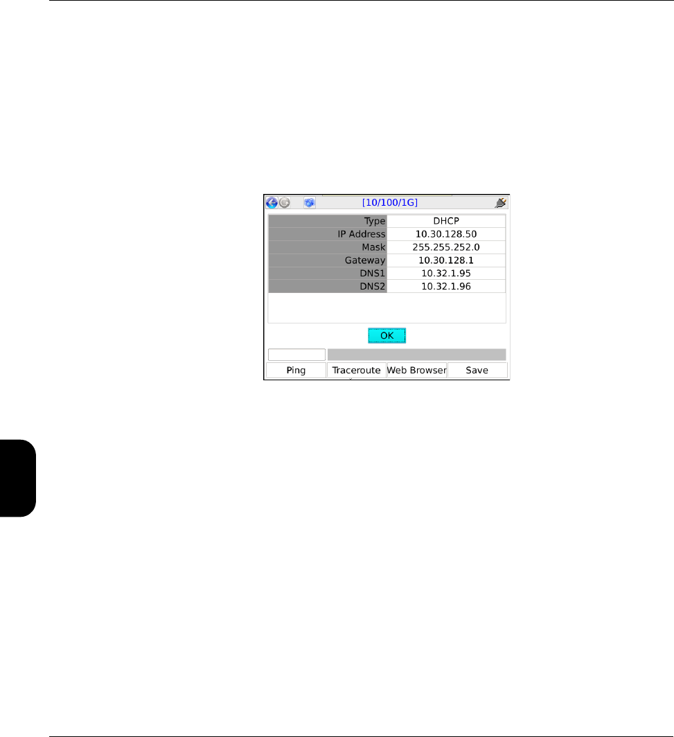
Verizon Base Unit User Guide Rev B PRELIMINARY 3/20/2014 Tech-X Flex® (P5)
5-4
Intro Wi-Fi 10/100 System IP/Video Specs
• The unit is properly connected to an active, networked device. For example, when using the
10/100/1G interface, the Ethernet cable must be properly connected. Or, for the Wi-Fi interface, the
unit must be within range of an active wireless node.
• The target network has an active DHCP server. In a home network, the DHCP server is normally
incorporated with the home router, in which case you may need to log into the router to ensure that
the DHCP server has not been disabled. See the router documentation for more information.
For DHCP operations, the server may return a second DNS address, which is shown for DNS2.
Otherwise, this field displays NA.
Figure 5-1 Successful IP Network Setup
5.2 Connection Info
This function reports the IP information that is currently assigned to the active interface and is identical to
the results screen from a successful IP Network Setup. For more information, see IP Network Setup on
page 5-2.
5.3 Ping
IP Ping is a basic connectivity test that verifies whether a specific IP address can be reached. It sends a
set of ICMP echo requests to an IP address and reports whether replies are successfully received. The
request is sent via the active interface of the unit and requires that routable IP information is assigned to
that interface. For more information, see IP Network Setup on page 5-2.
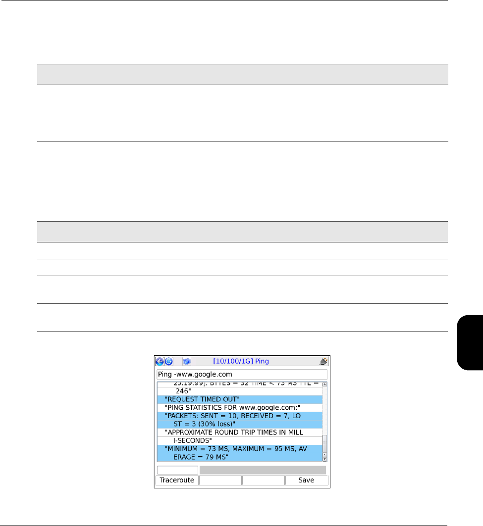
Tech-X Flex® (P5) Verizon Base Unit User Guide Rev B PRELIMINARY 3/20/2014
5-5
Intro
Wi-Fi
10/100
System
IP/Video
Specs
5.3.1 Setup - Ping
Table 5-2 Ping - Setup parameters
5.3.2 Results - Ping
Along with details about each individual ping request, the unit also reports the following summary
information:
Table 5-3 Ping - Results
Figure 5-2 Successful Ping results
Parameter Description
Destination Target address for the ping request, either a dotted IP address or a URL if a DNS
is available. For example:
208.22.58.142
www.google.com
Result Description
Packets Sent Number of ping requests sent to the address
Packets Received Number of ping requests reported as successfully received
Packets Lost Percentage of ping requests that were lost (Packets Sent - Packets
Received)
Approximate round trip
time in milliseconds
Average time for a ping requests to reach its destination and then for the
unit to receive the success report
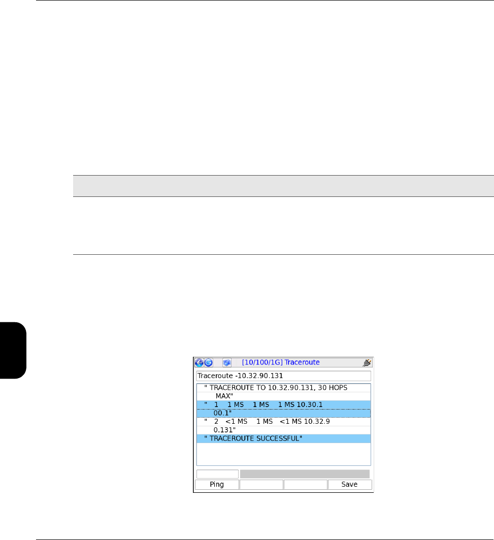
Verizon Base Unit User Guide Rev B PRELIMINARY 3/20/2014 Tech-X Flex® (P5)
5-6
Intro Wi-Fi 10/100 System IP/Video Specs
5.4 Traceroute
Provides a standard ICMP or UDP traceroute function that runs three concurrent traceroute processes
and reports every router “hop” along the path, up to 30 hops. The results provide a topological view of the
route that packets are using to reach the destination.
The request is sent via the active interface and requires that routable IP information is assigned to that
interface. For more information, see IP Network Setup on page 5-2.
5.4.1 Setup - Traceroute test
Table 5-4 Traceroute - Setup parameters
5.4.2 Results - Traceroute test
The unit reports the IP address of each sequential hop along the path to the target, along with the
roundtrip time required for each hop to receive the probe packet and the unit to receive
acknowledgement. Because three independent traceroute processes are run, three topology sets are
presented. An asterisk appears if a time cannot be determined, such as a response timeout when a
router cannot or will not return a response.
Figure 5-3 Successful Traceroute results
Parameters Description
Destination Target address for the traceroute request, either a dotted IP address or a URL if
a DNS is available. For example:
208.22.58.142
www.google.com

Tech-X Flex® (P5) Verizon Base Unit User Guide Rev B PRELIMINARY 3/20/2014
5-7
Intro
Wi-Fi
10/100
System
IP/Video
Specs
5.5 Web Browser
NOTE: The web browser is a purchasable option. Please contact Spirent for more information.
The Web Browser allows you to access web pages from the internet and view them on the screen. It
may be especially useful for verifying that internet access is available, beyond a simple ping test. If a
residential subscriber cannot view a web page but you can with the unit, you can normally conclude that
the trouble exists with the subscriber’s web browser, computer, or home network configuration. It may
also be used to verify that a DNS is available.
The Web Browser is similar to a browser used on a desktop computer, except that the smaller screen
may require more use of the scroll bars. Furthermore, aside from basic hyperlinks, most webpage
controls may not work correctly. In some cases, complex pages with extensive internal scripting may not
display correctly or at all, so it is recommended that you use simple, fast-loading web pages to perform
tests. In summary, the browser is intended as a testing tool, not as a fully-functional interface to the
internet.
To access the Web Browser, the active interface must be configured with valid, routable IP information.
For more information, see IP Network Setup on page 5-2.
5.5.1 Setup - Web Browser
Table 5-5 Web Browser - Setup parameters
Parameters Description
URL Target address of the web page to load, either a dotted IP address or a URL if a
DNS is available. For example:
208.22.58.142
www.google.com
Note the following:
• When entering a URL, case is unimportant because all characters are
converted to lower case when the browser is launched.
• The unit remembers the recent addresses you entered.
• The dropdown list may automatically include one or more commonly-used
websites.
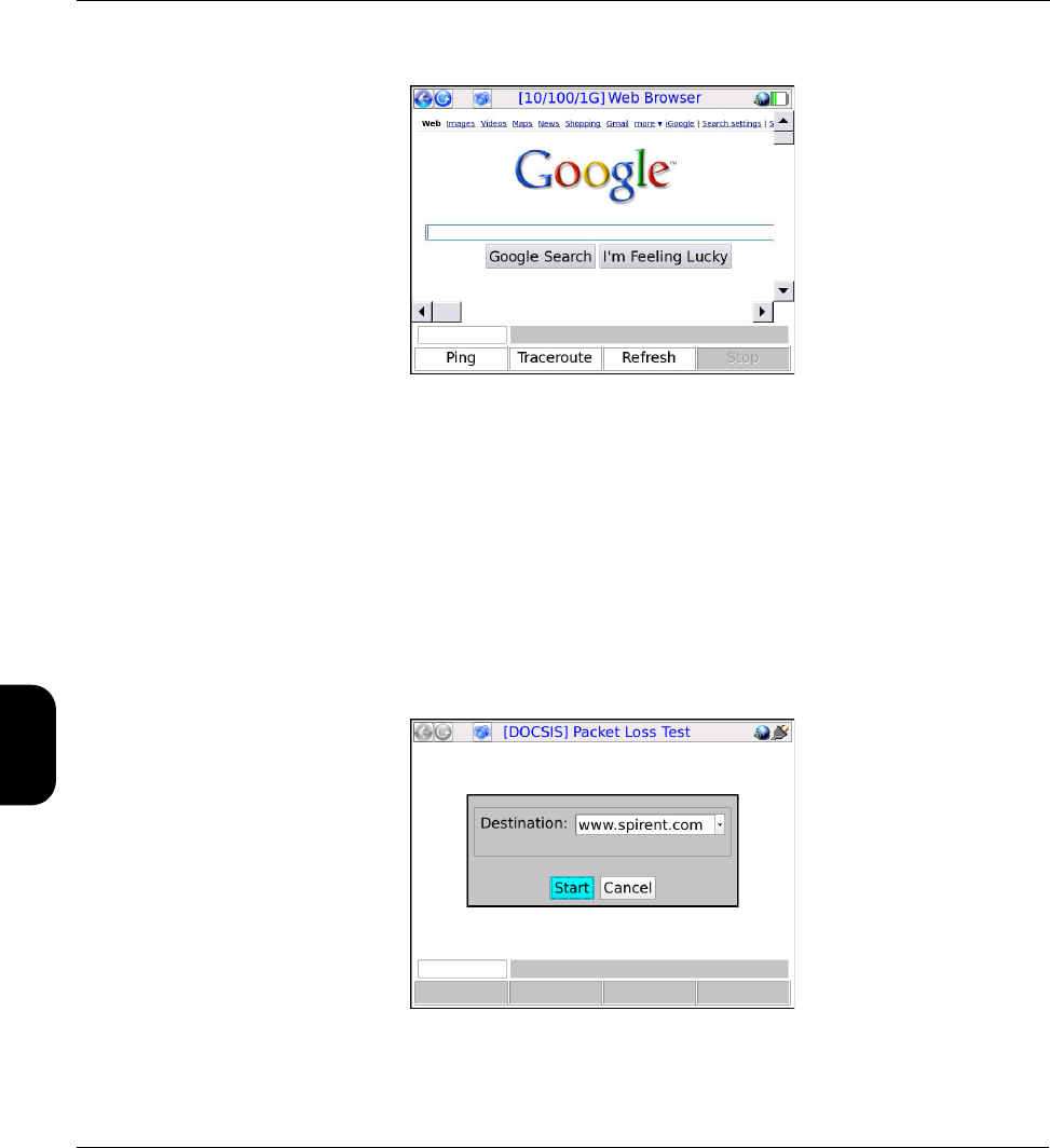
Verizon Base Unit User Guide Rev B PRELIMINARY 3/20/2014 Tech-X Flex® (P5)
5-8
Intro Wi-Fi 10/100 System IP/Video Specs
Figure 5-4 Web Browser, showing the Google™ website
5.6 Packet Loss Test
The Packet Loss Test runs a continuous series of ping tests, maintaining and presenting a set of
cumulative results as testing progresses. These results include the number of lost ping packets since the
beginning of the test.
5.6.1 Setup - Packet Loss Test
The setup requires only the Destination for the ping tests:
Figure 5-5 Packet Loss Test - Setup

Tech-X Flex® (P5) Verizon Base Unit User Guide Rev B PRELIMINARY 3/20/2014
5-9
Intro
Wi-Fi
10/100
System
IP/Video
Specs
CAUTION: You should select the destination for this test carefully. Because it effectively
sends a continuous stream of packets to a single host, it could be construed as
a denial-of-service attack by a third party that does not welcome such traffic.
5.6.2 Results - Packet Loss Test
The test runs indefinitely until manually stopped. Results are reported at approximately 1-second
intervals and are as follows:
Table 5-6 Packet Loss Test results
Measurement Description
# Sent Total number of ping requests sent since the beginning of the test.
# Recv The total number of ping requests that successfully received a reply, as of the end of
the respective reporting interval.
# Lost The total number of ping requests that have not yet received a reply, calculated as:
# Sent - # Received
Note that this number may fluctuate up and down, as a reply may be received in one
interval for a request sent in a previous interval. Therefore, at any given time during
ongoing testing, this number does not necessary represent a count of positively lost
packets, because some may still be in transit. Once a test is terminated, it will wait a
standard amount of time for any lingering requests to be acknowledged and/or time
out, so the count for the final interval will be an accurate count of loss for the entire
test.
% Lost The percent of packets lost since the beginning of the test, calculated as:
# Lost / # Sent
...using the cumulative counts for the respective interval only.
Min
Avg
Max
The minimum, average, and maximum roundtrip times since the beginning of the
test, not necessarily for the respective interval. Because these counts represent the
entire test, the following notes apply:
•The Min value cannot ever increase from one interval to the next, because new
minimums can only reduce the value.
•The Max value follows a similar logic except that it cannot decrease.
•The Avg value may fluctuate based on changing conditions during the testing
process. The longer the test runs, the more likely this value will stabilize as the
number of data points contributing to the calculations continues to increase.
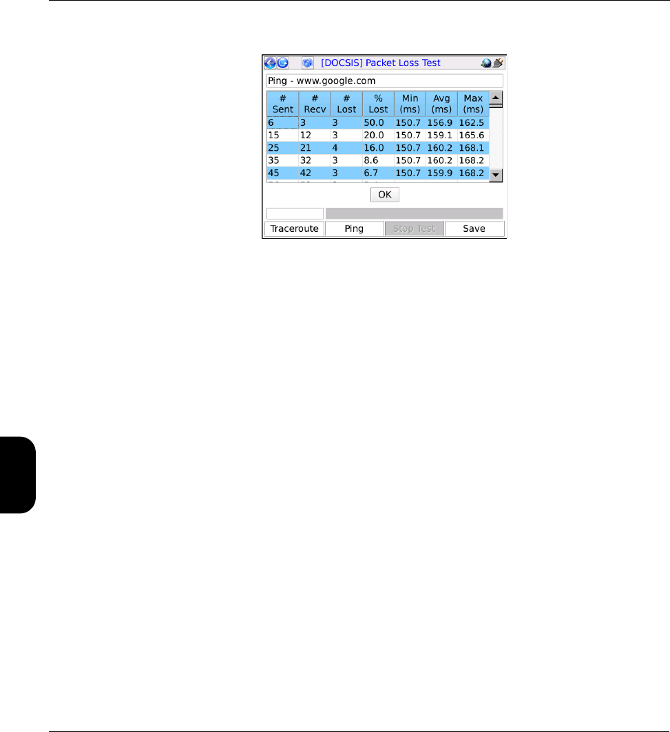
Verizon Base Unit User Guide Rev B PRELIMINARY 3/20/2014 Tech-X Flex® (P5)
5-10
Intro Wi-Fi 10/100 System IP/Video Specs
Figure 5-6 Packet Loss Test - Results
5.7 Throughput
The Throughput test calculates the maximum data rate to and from a specific endpoint, designed as a
basic upstream/downstream capacity measurement. The target endpoint of the test must be a computer
running a webserver application that is specifically configured for this test. For more information, see
Throughput server setup on page 5-12.
Note the following:
• While running this test, keep in mind that throughput in any direction can never be greater than the
slowest segment in the path. Therefore, for proper interpretation of results, you should have some
awareness of which segment is expected to have the lowest throughput under normal conditions.
• This test is based on a transfer of data over a TCP connection. TCP data rates may vary dynamically
during the course of transmission; therefore, results between different file sizes and different tests
may be inconsistent. In particular:
– Large file sizes may indicate a higher data rate than smaller sizes, because the endpoints will
have more time to optimize the TCP link.
– TCP involves retransmissions of lost data, which can have a varying effect depending on what
stage(s) of the file transfer that the retransmission(s) occur. For example, if loss occurs later in the
transfer when the TCP window size may be allowing larger units of transfer, a retransmission will
be more costly to the overall data rate.
In summary, while this test may be useful for determining a baseline for the user experience, it cannot
provide a precise or consistent data rate measurement at the lower data link layer.
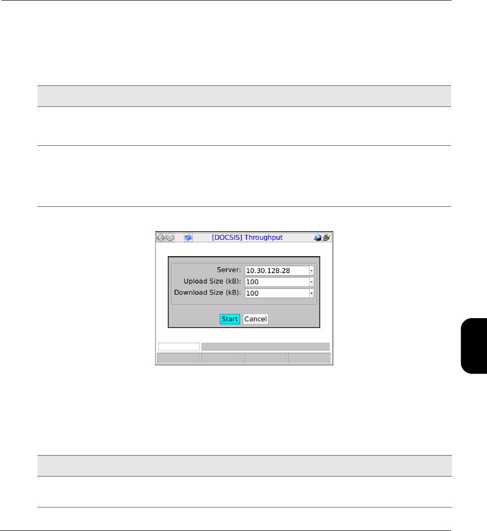
Tech-X Flex® (P5) Verizon Base Unit User Guide Rev B PRELIMINARY 3/20/2014
5-11
Intro
Wi-Fi
10/100
System
IP/Video
Specs
5.7.1 Setup - Throughput
The setup screen requires the following parameters:
Table 5-7 Throughput setup parameters
Figure 5-7 Throughput - Setup
5.7.2 Results - Throughput
The test produces the following results:
Table 5-8 Throughput results
Measurement Description
Server IP address of a properly-configured throughput server running on port 80 (see
Throughput server setup on page 5-12). A URL is also acceptable if a valid DNS
was assigned during IP Network Setup (see IP Network Setup on page 5-2).
Upload Size (kB)
Download Size (kB)
Total amount of data to send in each direction, up to 100,000 kilobytes each
direction. For each direction, the test measures the amount of time required to
send the respective amount of data and uses that measurement to calculate the
overall data rate. Larger amounts of data facilitate greater accuracy but increase
testing time and bandwidth consumption.
Measurement Description
Upload Rate
Download Rate
Maximum achievable data rates in both directions, averaged across the testing
period.
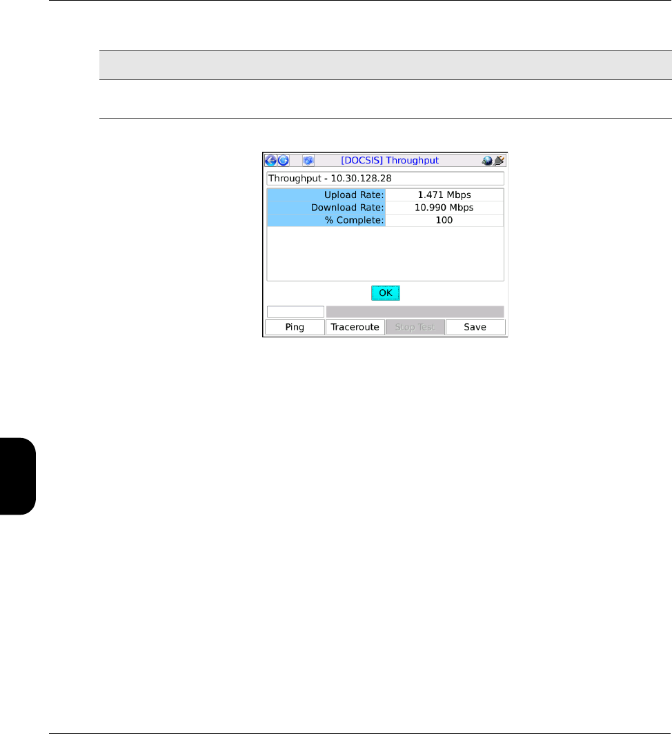
Verizon Base Unit User Guide Rev B PRELIMINARY 3/20/2014 Tech-X Flex® (P5)
5-12
Intro Wi-Fi 10/100 System IP/Video Specs
Figure 5-8 Throughput - Results
5.7.3 Throughput server setup
The Throughput test requires a testing destination that is specifically designed to recognize and process
throughput exchanges with the unit. This destination must be an HTTP (web) server running on a
networked computer and installed with Spirent-specific components. The following procedure is a broad
overview of server installation and setup.
NOTE: To accomplish this task successfully, a basic knowledge of web server administration and
python scripting is recommended. For assistance with setup and troubleshooting, please
contact Spirent.
1. Download and install the web server - The supported web server is the Apache HTTP Server,
available at the time of this writing at:
http://httpd.apache.org/download.cgi
You should select the most recent stable (alpha) release for your platform (Windows, etc.). Install it
using default parameters except for the requested web administrator email address, which you may
want to change to the real address of an administrator (perhaps yourself). Note the following:
• The server must be set to listen on port 80 for HTTP requests.
• Depending on the platform and installation type, you may need to manually start the server
following installation. See the Apache documentation for more information.
% Complete A progress counter that increments while the test is running, until it is 100%
complete.
Measurement Description

Tech-X Flex® (P5) Verizon Base Unit User Guide Rev B PRELIMINARY 3/20/2014
5-13
Intro
Wi-Fi
10/100
System
IP/Video
Specs
2. Download and install an ActiveState python package - At the time of this writing, the latest stable
python packages are available at:
http://www.activestate.com/activepython/downloads/
Default installation settings are recommended.
3. Retrieve and install the Spirent python scripts - You must place two python scripts (*.py) files in
the cgi-bin directory in the Apache installation area. These files are available from Spirent,
normally from the corporate/customer FTP site at the following address:
ftp.sab.spirentcom.com
For login credentials, please contact your account manager.
5.8 Speedtest
The Speedtest provides a standard internet-based maximum throughput test. By exchanging data with
an internet endpoint, it attempts to determine the maximum data rate supported in both the uplink and
downlink directions. Note that this test may put a temporary strain on the local network, as it is attempting
to exchange the maximum amount of data possible.
NOTE: Speedtest results are saved automatically following the completion of the test, using a system-
generated filename. This file is then staged for automatic upload to the Verizon field
management system. For more information, see About automatic result file upload on page 4-2.
5.8.1 Setup - Speedtest
The setup screen requires the following parameters:
Important note: The python scripts are currently configured for Windows usage only and require
that the system path environment variable contains the path to the python executable. If you are
using Windows, you should ensure that this variable is set correctly.
If you are using Linux or Unix instead, you must adjust the first line of each script to point to the
location of the python interpreter, for example:
#!/usr/bin/python
If the system is unable to locate the python interpreter based on this line, throughput testing will
fail. For more information, see the operating system documentation, python documentation,
and/or contact Spirent.
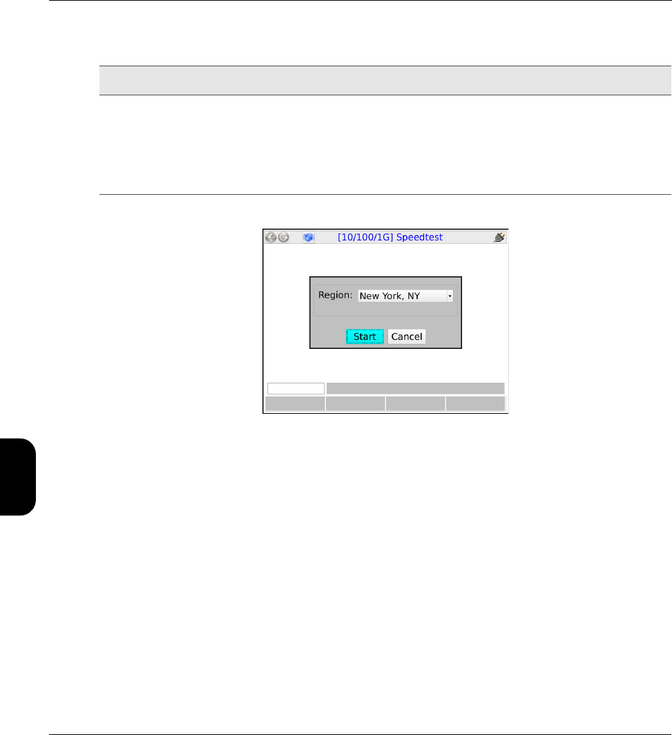
Verizon Base Unit User Guide Rev B PRELIMINARY 3/20/2014 Tech-X Flex® (P5)
5-14
Intro Wi-Fi 10/100 System IP/Video Specs
Table 5-9 Speedtest setup parameters
Figure 5-9 Speedtest - Setup
5.8.2 Results - Speedtest
NOTE: While the test is actively sending traffic, the screen presents a “collecting data” message and
does not update further until the traffic exchange is complete. It may take up to a minute to
complete this exchange, after which the final results are presented graphically.
The test produces a simple graphical display of the maximum speeds achieved for upload and download.
Measurement Description
Region General location of the target endpoint. The options in the list represent
designated endpoints that are specifically provided for this test. These locations,
along with the underlying IP addresses, are hardcoded with the unit firmware.
Normally, you should select the geographically closest location. For more
information on these locations, contact a local administrator. For more
information on augmenting this list, please contact Spirent.
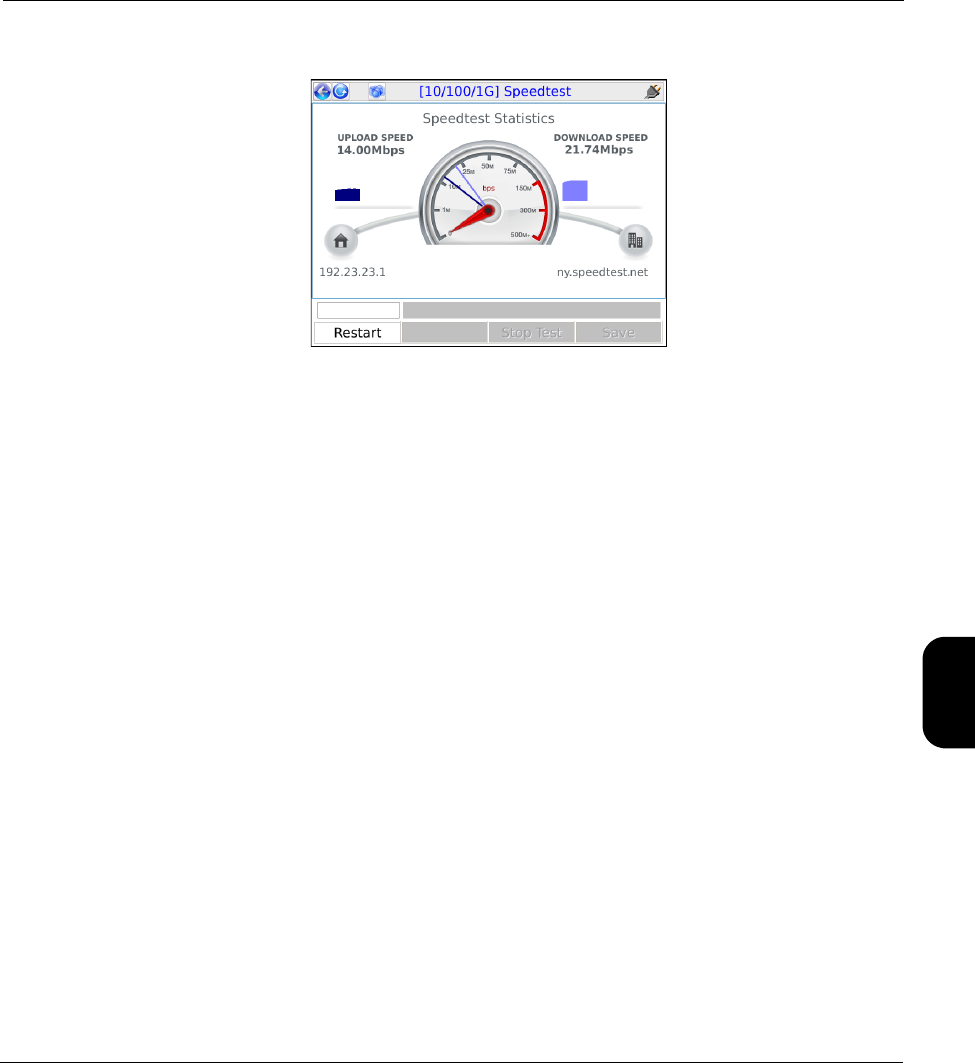
Tech-X Flex® (P5) Verizon Base Unit User Guide Rev B PRELIMINARY 3/20/2014
5-15
Intro
Wi-Fi
10/100
System
IP/Video
Specs
Figure 5-10 Speedtest - Results
5.9 IP Video testing
IP video testing support includes:
• Subjective quality assessment of viewer experience
• Comprehensive statistics on multimedia transport streams
• Video channel change times
Video testing support includes:
• “Active” testing, where the test set emulates a multicast endpoint and performs all actions necessary
to start and/or join the stream. Depending on the location of the test set, this type of testing can
provide the most comprehensive view of the actual subscriber experience.
• “Passive” testing, where the test set is connected between two existing endpoints and passively
monitors the video traffic between them. Passive testing is supported for multicast and unicast
streams.
Briefly, unicast vs. multicast is defined as:
•Unicast - A single stream between two specific endpoints. Unicast video is similar to any
conversation between distinct IP hosts, which in this case normally represent a video server and a
subscriber device such as an STB.
•Multicast - A system designed to transport a single video stream to multiple endpoints, reducing the
demands on network bandwidth due to redundant data. For more information, see About IP multicast
on page 5-35.

Verizon Base Unit User Guide Rev B PRELIMINARY 3/20/2014 Tech-X Flex® (P5)
5-16
Intro Wi-Fi 10/100 System IP/Video Specs
For any given interface, note that testing support may vary according to limitations specific to that
interface. Where appropriate, this documentation notes those variations.
Specific video functions include:
•Video QoS (Quality of Service) on page 5-16
•Change Channel on page 5-43
•Channel Guide Settings on page 5-45
5.9.1 Video QoS (Quality of Service)
NOTE: Video testing is a purchasable option. Please contact Spirent for more information.
This test provides subjective no-reference quality scores and MDI calculations on a specific IPTV
channel stream, along with a set of network parameters, picture frame statistics, and other transport
stream information.
For a single-ended, active test, the unit must emulate a video endpoint and initiate/join the stream, after
which it performs the quality assessment on the traffic sent directly to it. Some interfaces, such as the
10/100/1G interface, provide a bridging/mirroring mechanism where the unit can be placed between two
devices and passively monitor an existing stream. For more information on how the passive bridging
process works with the Ethernet interface, see Unit setup for passive testing on page 3-5.
For more details on how the quality assessment works, see How the analysis works - An overview on
page 5-37.
NOTE: The analysis focuses primarily on the data captured from the MPEG transport stream. For more
information about MPEG transport, see the information under Digital video concepts overview
on page 5-31, including About MPEG transport on page 5-33.
Setup - Video QoS
Note the following:
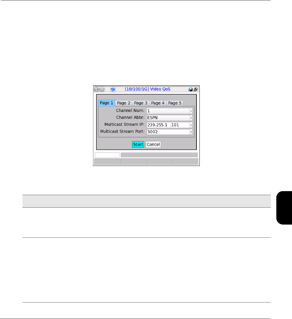
Tech-X Flex® (P5) Verizon Base Unit User Guide Rev B PRELIMINARY 3/20/2014
5-17
Intro
Wi-Fi
10/100
System
IP/Video
Specs
• For multicast testing, if the unit has an active channel guide, the display will first present a channel
selection screen when the test setup is initiated. After channel selection, the normal setup screen will
appear, with the certain parameters prepopulated, such as the IP address and port. The use of a
channel guide, if available, is generally recommended. For more information, see Channel Guide
Settings on page 5-45.
• When you run a test, the input parameters are stored as defaults for the next test and persist
between reboots. The defaults are stored separately for each interface that supports Video QoS
testing. For example, the settings used for testing from the 10/100/1G interface would be stored
separately from those used for the modular MoCA interface.
Figure 5-11 Multicast Video QoS Setup - Page 1 (with a channel guide)
Table 5-10 Video QoS test - Setup parameters
Parameter Description
Channel Num
Channel Abbr
For multicast video only, if a channel guide was used, the channel number and
abbreviation that was selected in the previous screen. If no channel guide is
active, these fields do not appear. For more information on channel guides, see
About channel guides on page 5-45.
Multicast Stream IP
-or-
Destination IP Addr
IP address of the video stream. For multicast video, if you selected a channel
from the channel guide, this field is automatically populated.
The IP address specified must reflect the destination IP address for video stream
packets; that is, the first address contained in the IP packet headers. For a
multicast stream, this will be a multicast IP address, not an IP address of a host
on the network under test. For a unicast stream, this must be the IP address of
the destination device on the network, such as an STB. For a discussion on
multicast packet addressing and transport versus unicast, see About IP multicast
on page 5-35.

Verizon Base Unit User Guide Rev B PRELIMINARY 3/20/2014 Tech-X Flex® (P5)
5-18
Intro Wi-Fi 10/100 System IP/Video Specs
Multicast Stream
Port
Destination IP Port
The destination UDP port associated with packets that contain the stream under
test. The unit determines which packets should be included in the audio/video
quality measurement based on the destination IP address and destination UDP
port pair. For multicast video, if you selected a channel from the channel guide,
this field is automatically populated.
As an option, you can select All Ports Open from the drop-down list which
indicates to ignore the port and use the IP address exclusively for identifying
video stream packets. In the case of unicast streams where packets are
addressed to a network device such as an STB, it can be difficult to determine
the UDP port(s) in use. Therefore, this option allows traffic analysis based on IP
address alone. While the STB may be receiving some data that is not part of the
video stream, it is likely that most traffic will be video data that qualifies for
analysis.
NOTE: For the most accurate results with the All Ports Open option, run
the test once to discover the precise port number, then restart the test
using that specific port.
In summary:
• This field indicates the logical port that the unit will monitor for video traffic, for
the specified IP address.
•The All Ports Open option is only applicable to measuring unicast streams
(for example, video-on-demand) using passive mode. The option allows the
unit to determine the destination UDP port of the packets containing the
stream under test dynamically.
Duration Duration of the test in seconds, or Continuous to run the test until manually
stopped.
Interval Interval at which to report a full set of current measurement results, applicable to
continuous tests only.
Encapsulation
Method
Encapsulation type of the stream(s) under test.
•RTP
•UDP
Parameter Description

Tech-X Flex® (P5) Verizon Base Unit User Guide Rev B PRELIMINARY 3/20/2014
5-19
Intro
Wi-Fi
10/100
System
IP/Video
Specs
Measurement
Method
Measurement method to use, which determines the type of data returned by the
test. For more information, see About MOS and R-factor calculations on
page 5-38 and MDI measurement overview on page 5-40.
•VQM - See Video quality measurement (VQM) overview and additional results
descriptions on page 5-37.
•MDI - See MDI measurement overview on page 5-40.
Note that this selection fundamentally changes the nature of the analysis and the
results that are returned. For the results from a VQM test, see Results - Video
QoS (VQM test) on page 5-24. For the results from an MDI test, see Results -
Video QoS (MDI test) on page 5-23.
IGMP Version Version of IGMP to use for multicast join/leave requests. This must reflect an
IGMP type in use on the network where the request is made.
Options include:
•IGMPV1 - IGMP version 1
•IGMPV2 - IGMP version 2
•IGMPV3 - IGMP version 3
Codec Video codec used for the stream under test.
•MPEG2
•MPEG4
•H264
Jitter Mode Type of jitter buffer emulation used.
Options include:
•FIXED - The jitter buffer uses a constant fixed delay. The jitter buffer is
bounded by a nominal and maximum delay, where the nominal delay dictates
the actual delay and the maximum delay dictates the maximum number of
packets that can be stored in the jitter buffer.
•ADAPTIVE - The jitter buffer is bounded by a minimum, nominal and
maximum delay, where the minimum delay dictates the minimal accepted jitter
buffer delay, nominal delay dictates the starting delay and the maximum delay
dictates the maximum delay of the jitter buffer. The maximum number of
packets that can be stored in the jitter buffer is a set fraction of the maximum
delay.
Parameter Description

Verizon Base Unit User Guide Rev B PRELIMINARY 3/20/2014 Tech-X Flex® (P5)
5-20
Intro Wi-Fi 10/100 System IP/Video Specs
GOP Type Video coder group of pictures (GOP) structure, representing the frame sequence
in use on the stream with respect to I, P, and B frames. This value is used only as
a default if the actual frame types and GOP structure cannot be dynamically
detected from the stream.
Options include:
•A - I-frames only, for example:
III…I
•B - One I-frame followed by P-frames, for example:
IPPP...PIPPP...
•C - One I-frame followed by P- and B-frames with two B-frames between each
pair of anchor frames, for example:
IBBPBBP...BBIBBP...
•D - All P-frames, for example:
PPPP...P
•E - One I-frame followed by P- and B-frames with one B-frame between each
pair of anchor pictures, for example:
IBPBP...BIBP...
For more information about MPEG pictures, see About IP multicast on
page 5-35.
GOP Length Number of frames in a group of pictures (GOP) on the stream, related to the
GOP type. This is essentially the I-frame update interval; that is, the number of
frames from one I-frame to the next. This value is used only as a default if the
actual frame types and GOP structure cannot be dynamically detected from the
stream.
Range:
1 - 100
Loss Sensitivity This defines how much the quality assessment should be sensitive towards
packet loss and discards. A higher value indicates the video stream is more
sensitive to packet loss/discard. When set higher, the calculation model will
respond more rapidly to packet loss on the network under test, and packet loss
will have a greater impact on the calculated score. If set lower, the results will be
less affected by packet loss. This setting makes the analysis tunable for different
varieties of encoders and various network environment conditions.
Parameter Description

Tech-X Flex® (P5) Verizon Base Unit User Guide Rev B PRELIMINARY 3/20/2014
5-21
Intro
Wi-Fi
10/100
System
IP/Video
Specs
Concealment Level This parameter defines the effectiveness of the packet loss concealment
algorithm use by the encoder. A higher value indicates a better PLC algorithm.
This setting helps compensate for reduced packet loss due to regeneration by
technologies such as forward error correction (FEC). In other words, it affects
how sensitive the quality assessment is to packet loss, with some similarity to the
loss sensitivity setting. A higher setting indicates that overall packet loss will
affect the quality score less. A setting of zero or none indicates no concealment,
meaning that packet loss will have the most impact to video quality, with respect
to this parameter's influence.
Valid values are:
0 to 50
Complexity This parameter defines the video content coding factor. A higher value indicates
the video stream can be encoded using a lower bit rate to achieve a given
quality.
Valid values are:
-50 to 50
Original Quality Original picture quality. This value represents the subjective quality of the video
before encoding, which is the theoretical maximum that the quality ever could be
after encoding, transport, and decoding.
Valid values are:
256 - 1280, proportional to the 1.0 to 5.0 MOS range, scaled by a factor of 256.
For example, a value of 1242 is equivalent to a MOS of 4.85.
Parameter Description

Verizon Base Unit User Guide Rev B PRELIMINARY 3/20/2014 Tech-X Flex® (P5)
5-22
Intro Wi-Fi 10/100 System IP/Video Specs
Coder Class Video coder class, which describes the ability of the stream to tolerate packet
loss with respect to perceived quality. The coder class is determined by two
contributing factors:
• Codec - Some codecs, particularly older codecs, are very sensitive to packet
loss and degrade very quickly with small amounts of loss.
• Error correction and concealment - A number of loss mitigation techniques
may be employed to conceal packet loss, typically involving coordination
between the video server and client where checksum and other validation
methods allow missing data to be supplemented.
The specified value determines how heavily the analysis weights the effects of
packet loss. For example, if you specify an operation at high rates of loss, any
detected loss will have less of an effect on final quality scores. This is normally a
static setting on any given network that does not change between tests.
Valid values are:
•A - Stream can operate over networks with up to 20% packet loss
•B - Operation with up to 10% loss
•C - Operation with up to 5% loss
•D - Operation with up to 0.5% loss
International Code Country/continent code, used to adjust quality scores based on cultural
differences in different global regions. For example, subjective human testing
using the same video stream have indicated that MOS scores in Japan are
typically lower than those found in Europe and North America. It should be noted
that this setting is purely subjective based on existing statistical data and cannot
be assured to accurately represent any particular individual.
Valid values are:
•NA - North America
•SA - South America
•EU - Europe
•AF - Africa
•AS - Asia
•JP - Japan
•AUS - Australia
Parameter Description
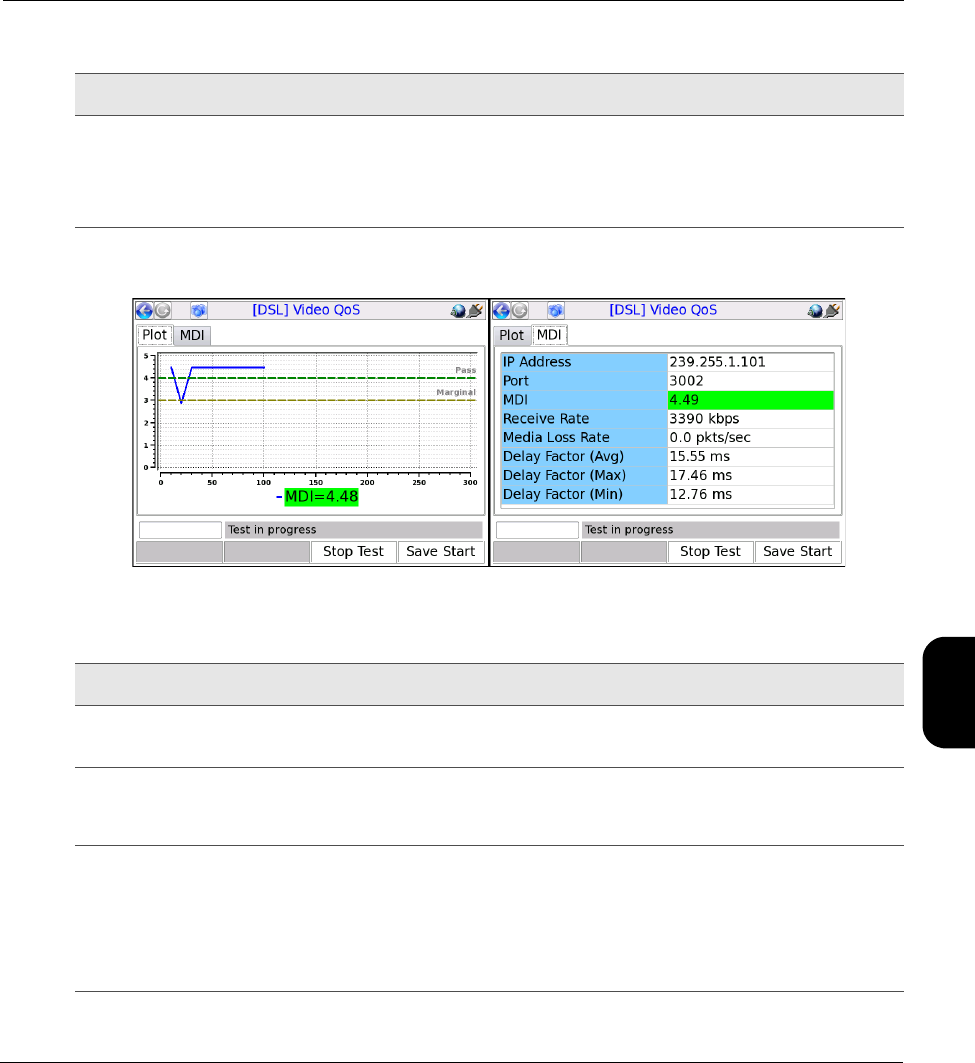
Tech-X Flex® (P5) Verizon Base Unit User Guide Rev B PRELIMINARY 3/20/2014
5-23
Intro
Wi-Fi
10/100
System
IP/Video
Specs
Results - Video QoS (MDI test)
Figure 5-12 Video QoS results - MDI test
Nominal Rate Payload media rate (audio and video) in kbps, used in calculating the MDI delay
factor.
Valid values are:
0 - 20000, where 0 indicates auto-detection of rate.
Parameter Description
Result Description
IP Address
Port
IP address and port of the media stream, specified at test launch.
Receive Rate Speed of frames received, in kbits/sec. For VQM testing, this is the receive rate
of the video or audio stream, as applicable. For MDI testing, this is the receive
rate of the PCR stream.
MDI
Media Loss Rate
Delay Factor (Avg)
Delay Factor (Max)
Delay Factor (Min)
See MDI measurement overview on page 5-40.
NOTE: The MDI result is colored green or red according to the fixed
pass/fail thresholds shown in the Plot tab.
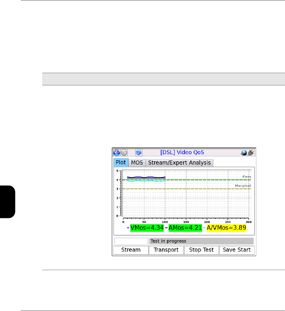
Verizon Base Unit User Guide Rev B PRELIMINARY 3/20/2014 Tech-X Flex® (P5)
5-24
Intro Wi-Fi 10/100 System IP/Video Specs
Results - Video QoS (VQM test)
Test results are presented in three different screens, each of which has two different pages. Use the
appropriate function key to switch between screens. Note the following:
• All quantitative measurements apply to the reporting period only. No measurements are cumulative.
• Unless indicated otherwise, any reference to “packets” means MPEG packets, not IP packets.
Table 5-11 Video QoS results - Summary results, Plot tab
Result Description
MOS graph Displays graph of calculated VMos, AMos, and A/VMos, which updates regularly for
continuous tests. The graph assumes a fixed score of 4.0 as passing and 3.0 as
marginal with coloring as follows:
•Green - Passing (above 4.0)
•Yellow - Marginal (between 3.0 and 4.0)
•Red - Failing (below 3.0)
The standards for any given architecture may differ. For more information on MOS
scoring, see About MOS and R-factor calculations on page 5-38.
Figure 5-13 VQM MOS graph

Tech-X Flex® (P5) Verizon Base Unit User Guide Rev B PRELIMINARY 3/20/2014
5-25
Intro
Wi-Fi
10/100
System
IP/Video
Specs
Table 5-12 Video QoS - Summary results, MOS tab
Table 5-13 Video QoS - Summary results, Stream/Expert Analysis tab
Result Description
IP Address
Port
IP address and port of the media stream, specified at test launch.
V MOS
A MOS
A/V MOS
See About MOS and R-factor calculations on page 5-38.
NOTE: Results are colored green or red according to the fixed pass/fail
thresholds shown in the Plot tab.
Result Description
Codec Type Stream type, as defined in ITU Spec ISO/IEC 13818-1.
For valid values, see Table 5-21, Other recognized transport streams/PID types on
page 5-30.
Image Size Horizontal resolution, indicating the left-right size of the image, in pixels.
-and-
Vertical resolution, indicating the top-bottom size of the image, in pixels.
Image Type Type of the image.
Valid values are:
•SDTV
•HDTV
Degradation
from Loss
Percentage of the overall quality degradation that can be attributed to network packet
loss.
Degradation
from Jitter
Percentage of the overall quality degradation that can be attributed to jitter buffer
discards.
Degradation
from Codec
Type
Percentage of the overall quality degradation that can be attributed to video
encoder/decoder selection.
Degradation
from Delay
Percentage of the overall quality degradation that can be attributed to delay.

Verizon Base Unit User Guide Rev B PRELIMINARY 3/20/2014 Tech-X Flex® (P5)
5-26
Intro Wi-Fi 10/100 System IP/Video Specs
Table 5-14 Video QoS - Stream results, Stream Metrics tab
Table 5-15 Video QoS - Stream results, Stream Description tab
Result Description
Frames Total number of frames received, by type.
Lost Total number of packets lost containing data for the respective frame type; for
example, the total number of packets lost containing I-frame data. These results
are packet counts, not frame counts.
NOTE: If packets for one frame type show an inordinate amount of loss
compared to others, there may be a problem with network congestion
and/or configuration. For example, some NEs may be configured to
discard video B-frame data during periods of heavy congestion.
Discards Total number of packets discarded by the jitter buffer emulator containing data for
the respective frame type; for example, the total number of packets discarded
containing I-frame data. These results are packet counts, not frame counts.
Impairments Total number of frames errored, by type. A frame is considered errored if a single
packet containing data for it is lost or discarded.
FEC Effect Calculated effectiveness of forward error correction (FEC) if it were applied to the
stream. This value represents the potential effectiveness of applied FEC, not the
effectiveness of previously-applied FEC.
Opt FEC Blk Size Number of packets in an FEC block which is used when calculating the FEC
effectiveness.
Opt FEC Crct Pkts Number of correctable packets in an FEC block which is used when calculating
the FEC effectiveness.
Peak/Mean Rcv
Rate
Ratio of peak packet receive rate to the mean receive rate.
Result Description
GOP Type GOP structure type of the stream. If the structure was detected by the analysis,
this value represents the detected structure. Otherwise, it represents the default
specified at test launch.
For details on possible values, see Setup - Video QoS on page 5-16.
GOP Length GOP length on the stream; that is, the total number pictures in a single GOP. If
the structure was detected by the analysis, this value represents the detected
structure. Otherwise, it represents the default specified at test launch.

Tech-X Flex® (P5) Verizon Base Unit User Guide Rev B PRELIMINARY 3/20/2014
5-27
Intro
Wi-Fi
10/100
System
IP/Video
Specs
Table 5-16 Video QoS - Stream results, Video Scores tab
Receive Rate Speed of frames received, in kbits/sec. For VQM testing, this is the receive rate
of the video or audio stream, as applicable. For MDI testing, this is the receive
rate of the PCR stream.
Peak Rcv Rate Peak speed of frames received, in kbits/sec. For VQM testing, this is the peak
receive rate of the video stream. For MDI testing, this is the peak receive rate of
the PCR stream.
Result Description
VSTQ Video service transmission quality. This is a codec-independent measure related
to the ability of the bearer channel to support reliable video.
Valid values are:
0 - 100
VSPQ Video Service Picture Quality. This is a codec-dependent measure of the
subjective quality of the decoded video stream. It is equivalent to a V-MOS score,
using a different scoring range.
0 - 100
Gap VSPQ Video Service Picture Quality during gap state periods. This is a codec-dependent
measure of the subjective quality of the decoded video stream. It is equivalent to a
V-MOS score, using a different scoring range.
Burst VSPQ Video Service Picture Quality during burst state periods. This is a codec-
dependent measure of the subjective quality of the decoded video stream. It is
equivalent to a V-MOS score, using a different scoring range.
VSMQ Video Service Multimedia Quality. This is a codec-dependent measure of the
subjective quality of the decoded audio and video stream. It is equivalent to an
AV-MOS score, using a different scoring range.
Valid values are:
0 - 100
EPSNR Estimated average peak signal-to-noise ratio value for pictures in the stream, in
dB. This value is derived based on other metrics and is not measured directly.
Result Description

Verizon Base Unit User Guide Rev B PRELIMINARY 3/20/2014 Tech-X Flex® (P5)
5-28
Intro Wi-Fi 10/100 System IP/Video Specs
Table 5-17 Video QoS - Transport results, Stream Metrics tab
Table 5-18 Video QoS - Transport results, MPEG Stats tab
Result Description
Packets Discarded Number of packets discarded. Packets may be discarded by the jitter buffer
emulator for the following reasons, similar to an actual jitter buffer:
• The buffer is too full to handle all incoming packets
• A packet arrives too late to contribute to the media presentation
OOS Packets Number of video/audio stream packets that arrived out of sequence, as detected
by the jitter buffer emulator.
Burst Loss Rate Average percentage of packets lost and/or discarded during burst periods.
NOTE: For further information about bursts and gaps, see About gap and
burst states on page 5-39.
Burst Length Average burst period length in milliseconds.
Gap Loss Rate Average percentage of packets lost and/or discarded during gap periods.
Gap Length Average gap period length in milliseconds.
Result Description
MPEG Sync Loss Number of times that the sync byte of a packet header was errored or not present
for two consecutive transport stream packets.
MPEG Sync Byte
Err
Number of times that a transport stream sync byte did not appear following a 188-
byte, 204-byte, or 208-byte transport stream packet.
MPEG Cont Err Number of times that the continuity count of a received packet did not increment
by one, as compared to the previous packet. The continuity count is a 4-bit field in
the packet header that increments from 0 - 15 for each transmitted packet,
resetting at zero as necessary. Continuity count errors are normally caused by lost
or out-of-sequence packets.
NOTE: This result may be reported at different granularities. When reported
at the transport stream PID level, it represents errors associated with
packets assigned to that PID. When reported at the elementary stream
level, it represents errors associated with packets for the respective
elementary stream.

Tech-X Flex® (P5) Verizon Base Unit User Guide Rev B PRELIMINARY 3/20/2014
5-29
Intro
Wi-Fi
10/100
System
IP/Video
Specs
Table 5-19 Video QoS - Transport results, Jitter/Delay Stats tab
NOTE: Not all stream types defined in ISO/IEC 13818-1 are supported. Any packets from unsupported
types are discarded and excluded from all test results.
MPEG Trnspt Err Number of packets that indicated a transport error, by means of the transport error
bit in the packet header. The transport error bit is set to "1" when at least one
uncorrectable bit error exists in the packet.
NOTE: This result may be reported at different granularities. When reported
at the transport stream PID level, it represents errors associated with
packets assigned to that PID. When reported at the elementary stream
level, it represents errors associated with packets for the respective
elementary stream.
PCR Repetition Err Number of times that the interval between PCR (program clock reference)
transmissions exceeded 100 ms, if the discontinuity indicator is not set. The PCR
is used as a time synchronization tool between the encoder and decoder. If the
discontinuity indicator is not set, the encoder expects a 100 ms or smaller interval
between PCRs. Both the PCR and discontinuity indicator are part of the packet
header.
PTS Err Number of times that the PTS (presentation time stamp) repetition period
exceeded 700 milliseconds. A PTS is a part of the PES packet header and
indicates the exact moment when a video frame or an audio frame has to be
presented to the user. It is important for synchronization of the audio and video
streams. Note that this parameter is always reported as NA for elementary
streams that do not have presentation time stamps.
Result Description
MAPDV The true average mean-absolute packet delay variation in milliseconds. This type
of measurement is sometimes referred to as jitter.
For more information on MAPDV, see About packet delay variation (PDV) on
page 5-39.
PPDV The packet-to-packet delay variation in milliseconds, according to a calculation
model defined in RFC 3550.
For more information on PPDV, see About packet-to-packet delay variation
(PPDV) on page 5-40.
Result Description

Verizon Base Unit User Guide Rev B PRELIMINARY 3/20/2014 Tech-X Flex® (P5)
5-30
Intro Wi-Fi 10/100 System IP/Video Specs
Table 5-20 Supported stream types/names
Table 5-21 Other recognized transport streams/PID types
Stream type value Stream type name
2 or 128 MPEG-2 VIDEO
3 MPEG-1 Layer II AUDIO
4 MPEG-2 AUDIO
5 MPEG-2 Private
6 (with MPEG descriptor_tag 86) Teletype
6 (with MPEG descriptor_tag 106)
-or-
129
DOLBY AC-3 AUDIO
11 DSM-CC
15 MPEG-2 AAC AUDIO
16 MPEG-4 VIDEO (Part 2)
17 MPEG-4 AAC AUDIO
27 MPEG-4 VIDEO (H.264)
255 UNKNOWN STREAM
Name/abbrev. Stream type
ECM Entitlement Control Messages represent private conditional access
information that specifies control words and possibly other stream-
specific parameters related to scrambling and/or other facets of
access control. When the Conditional Access (CA) descriptor is found
in the TS_program_map_section (table_id=0x02) as specified
in ISO/IEC 13818-1), the CA_PID specifies packets containing
program-related access information such as ECM's. Its presence as
program information indicates that it is applicable to the entire
program. Its presence as extended ES (Elementary Stream)
information indicates it is applicable to the associated program
element.

Tech-X Flex® (P5) Verizon Base Unit User Guide Rev B PRELIMINARY 3/20/2014
5-31
Intro
Wi-Fi
10/100
System
IP/Video
Specs
Digital video concepts overview
About basic video and audio compression
Compression techniques are vital to allow modern communication networks to handle the transmission
of packetized digital video. For example, without compression, a video stream with pixelized image
frames would require a large amount of data, far too much for efficient transport across networks to
multiple subscribers.
Video compression involves multiple stages, beginning with the removal of spatial similarities from
individual frames using techniques similar to JPEG (Joint Photographic Experts Group) compression.
Then, similarities between adjacent frames are determined and removed from the stream, using complex
algorithms to reuse identical data that was already transmitted and to “predict” data where future
changes can be estimated. These processes serve to reduce the two primary forms of redundancy:
•Spatial redundancy - Within any given video frame, certain data may be redundant, such as large
portions of the same color or geometrical design. In this situation, compression may be employed to
represent portions of the frame as smaller mathematical values, rather than expressing every single
pixel individually, when many pixels are the same.
•Temporal redundancy - Adjacent video frames often have many similarities, especially with video of
still or slow-moving objects. In this case, sequential frames may have redundant information
expressed over time as the video is played.
In the end, the encoders/decoders effectively form a system where the technology is able to interpolate
redundant data, without the need to transmit it. This system allows for more efficient network capacity
utilization when transporting audio/video streams over communications networks.
Frame types
As part of the reduction in redundancy, the video is compressed and reorganized into three different
frame types, serving individual roles as follows:
EMM Entitlement Management Messages represent private conditional
access information that specifies the authorization levels or the
services of specific decoders. They may be addressed to single
decoders or groups of decoders. When the CA descriptor is found in
the CAT section (table_id=0x01) the CA_PID points to packets
containing system-wide and/or access control management
information such as EMMs.
Name/abbrev. Stream type

Verizon Base Unit User Guide Rev B PRELIMINARY 3/20/2014 Tech-X Flex® (P5)
5-32
Intro Wi-Fi 10/100 System IP/Video Specs
•I-frames (or “Intra pictures”) - I-frames are coded without reference to other pictures. That is, they
contain the full dataset required to render a video frame and do not interpolate based on references
to other frames. Therefore, they may employ compression to reduce spatial redundancy, but cannot
reduce temporal redundancy. I-frames are critically important for providing references to other frames
and serve as access points in the bitstream where decoding can begin. Because other frame types
do reduce temporal redundancy based on a dependence to the I-frames, the loss of I-frames in a
video stream has the most significant impact.
•P-frames (or “Predictive pictures”) - P-frames are interspersed between I-frames and allow a
combination of spatial and temporal redundancy. They can use internal spatial coding like I-frames,
but they can also derive data through references to previous I and P-frames. Through this
referencing, a P-frame can render the picture without a full pixel-by-pixel dataset, using redundant
information presented in preceding frames.
•B-frames (or “Bi-directional predictive pictures”) - B-frames are a further extension of the P-
frame predictive methodology, except that they may reference preceding and/or following I and/or P-
frames. The use of B-frames allows the highest degree of picture quality with the most efficient
compression. When a B-frame references a frame that comes after itself, the decoder must have
received the referenced frame before the B-frame can be decoded, making the frame order different
from the actual display order. Therefore, B-frames can cause a delay in the decoding process,
because the decoder must buffer the input while reordering the frames for display. Of the three, the
loss of a B-frame generally causes the least impact to picture quality.
At the data level, a frame is divided into slices which represent horizontal sections of the frame. Each
slice is further divided into macroblocks which represent rectangular sections of the slice. This
organizational structure is the reason that digital video exhibits “rectangular” errors when data becomes
corrupted, rather than the general fuzz and/or static caused by a poor analog signal. For example:
• If macroblock data is missing or corrupted, the video typically shows rectangles of missing picture on
the screen, amidst an otherwise clear picture. Likewise, if a whole slice can’t be rendered, a larger
rectangular portion is missing.
• If whole frame data is missing or corrupted, the video may freeze on certain pictures altogether,
rendering the last known frame while waiting for new frame data.
GOP types
For any video stream, a set of frames is called a group of pictures or GOP, with the specific sequence
known as the GOP structure. A common GOP structure would include one I-frame, followed by two B-
frames, then followed by one P-frame, and so on, represented as “IBBPBBP…" The following figure
represents a simplified diagram of frame reference and interpolation, using a typical GOP structure:
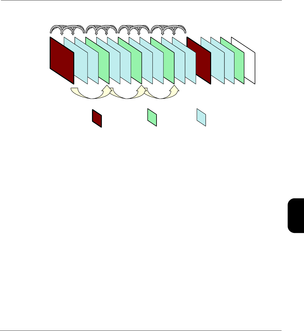
Tech-X Flex® (P5) Verizon Base Unit User Guide Rev B PRELIMINARY 3/20/2014
5-33
Intro
Wi-Fi
10/100
System
IP/Video
Specs
Figure 5-14 Compressed video stream frames
Audio compression
Audio compression has some similarity to video compression, in that techniques may be used to
eliminate redundant data. Furthermore, audio exhibits the concept of “masking,” where one frequency
may mask another and the human ear is unable to perceive it. Because it is unnecessary to transmit any
data for sounds that will never be heard, the removal of this data from the original audio stream provides
further possibilities for data reduction.
Additional details of encoding, decoding, and compression algorithms are complex and beyond the
scope of this document.
About MPEG transport
The MPEG standards refer broadly to a set of protocols for transporting compressed audio/video
programs over a communications network, such that a decoder can properly reconstruct the audio/video
programs at the destination. It is overseen by the Moving Picture Experts Group
(http://www.chiariglione.org/mpeg/).
A fundamental concept of MPEG transport is the “program,” the higher-level entity that end users receive
when they select a “channel.” Fully-decoded, an MPEG program is the entire dataset required to present
a single multimedia experience to the user, such as the complete and synchronized audio/video streams
required to watch a single IPTV channel.
The preparation of the audio/video programs has two fundamental stages:
I frames P frames B frames

Verizon Base Unit User Guide Rev B PRELIMINARY 3/20/2014 Tech-X Flex® (P5)
5-34
Intro Wi-Fi 10/100 System IP/Video Specs
•Elementary stream - The elementary stream is the basic compressed audio or video bitstream. In
the case of a video stream, this is the original content segmented into macroblocks, slices, and
frames, then packetized with header information required to reconstruct the stream at the far end. An
elementary stream is a single stream of video or audio only, relying on the transport stream layer to
associate it with other streams and create the concept of a program.
•Transport stream - Once constructed, one or more elementary streams are packetized into a
transport stream that provides all the instructions necessary to identify the data associated with a full
program, synchronize with the encoder, and reconstruct and present the audio/video program
properly. The transport stream includes the program clock reference or PCR, which provides the
critical data required for the decoder to synchronize its internal clock with that of the encoder. Without
synchronization, the decoder would be unable to recreate the video with the same timing as it was
encoded. Furthermore, the transport stream includes information such as:
–Packet identifiers or PIDs - Used as unique identifiers for individual elementary streams, as well
as program-specific information as described below.
–Program map table or PMT - Lists the elementary streams in the transport stream and identifies
the respective program(s) to which they belong. A program includes one or more elementary
streams, typically one video elementary stream and one or more audio elementary streams.
–Program association table or PAT - Lists all the programs included in the transport stream, as a
high-level list of all programs available to the decoder (or in other words, channels available to the
end user). When a program is selected for decoding, the decoder uses the program identifier in
the PAT to look up the required streams in the PMT.
–Conditional access table or CAT - Includes pointers to the PIDs that contain the entitlement
control/management messages needed to unscramble audio/video content, useful for
subscription-based services where access is limited.
Once completed, a transport stream is a sequence of 188-byte MPEG packets, ready for encapsulation
and transport over a communications network. The header data of transport streams, as well as that of
packetized elementary streams, is extremely useful for performing audio/video quality analysis, and
therefore provides the great majority of data used to calculate quality scores and other metrics.
With respect to degradation that may be caused during transport, the impact on audio/video quality
depends heavily upon the specific portion of the transport stream that is affected. For example, at the
lowest level, a loss of macroblock data may only cause a momentary anomaly in the display, perhaps not
even perceptible by the viewer. At the other extreme, a loss of MPEG transport header data, such as a
loss of synchronization, can cause the complete loss of the video altogether. For this reason, modern
analysis techniques must carefully consider the nature of loss and its respective impact on quality.
Overall, it should be noted that the descriptions here are highly-simplified, provided as a general
overview only. The full architecture of a complete MPEG transport stream is multi-layered and very
complex, beyond the scope of this document to describe.
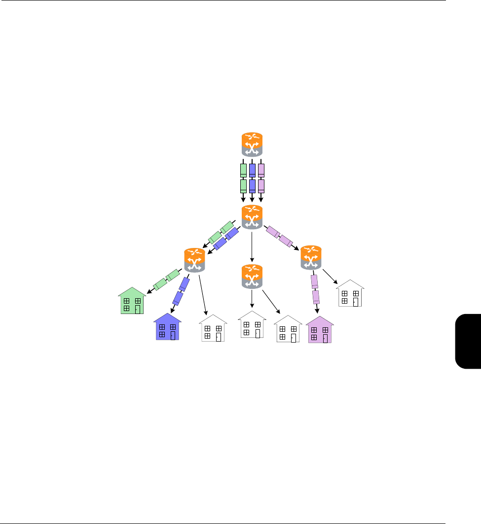
Tech-X Flex® (P5) Verizon Base Unit User Guide Rev B PRELIMINARY 3/20/2014
5-35
Intro
Wi-Fi
10/100
System
IP/Video
Specs
About IP multicast
IP multicast is a set of protocols that allows a single IP packet to be sent to multiple hosts (that is, “group
members”) without the need to send multiple redundant copies of the same packet from the source. It
serves to alleviate network congestion when multiple hosts need to receive the same traffic, such as the
case where multiple IPTV subscribers are watching the same channel and each will ultimately receive
the exact same data payload.
Consider the following diagram, which represents a small network without multicasting:
Figure 5-15 Hypothetical network without group multicasting
In the previous figure, three subscribers are watching the same channel. The shaded packets represent
the unicast IP streams required to deliver the service. The IP payload in each stream, however, is exactly
the same, resulting in a redundancy that creates congestion and scalability issues.
Alternatively, consider the following figure, which illustrates group multicasting:
R2
R3
R1
R4
R5
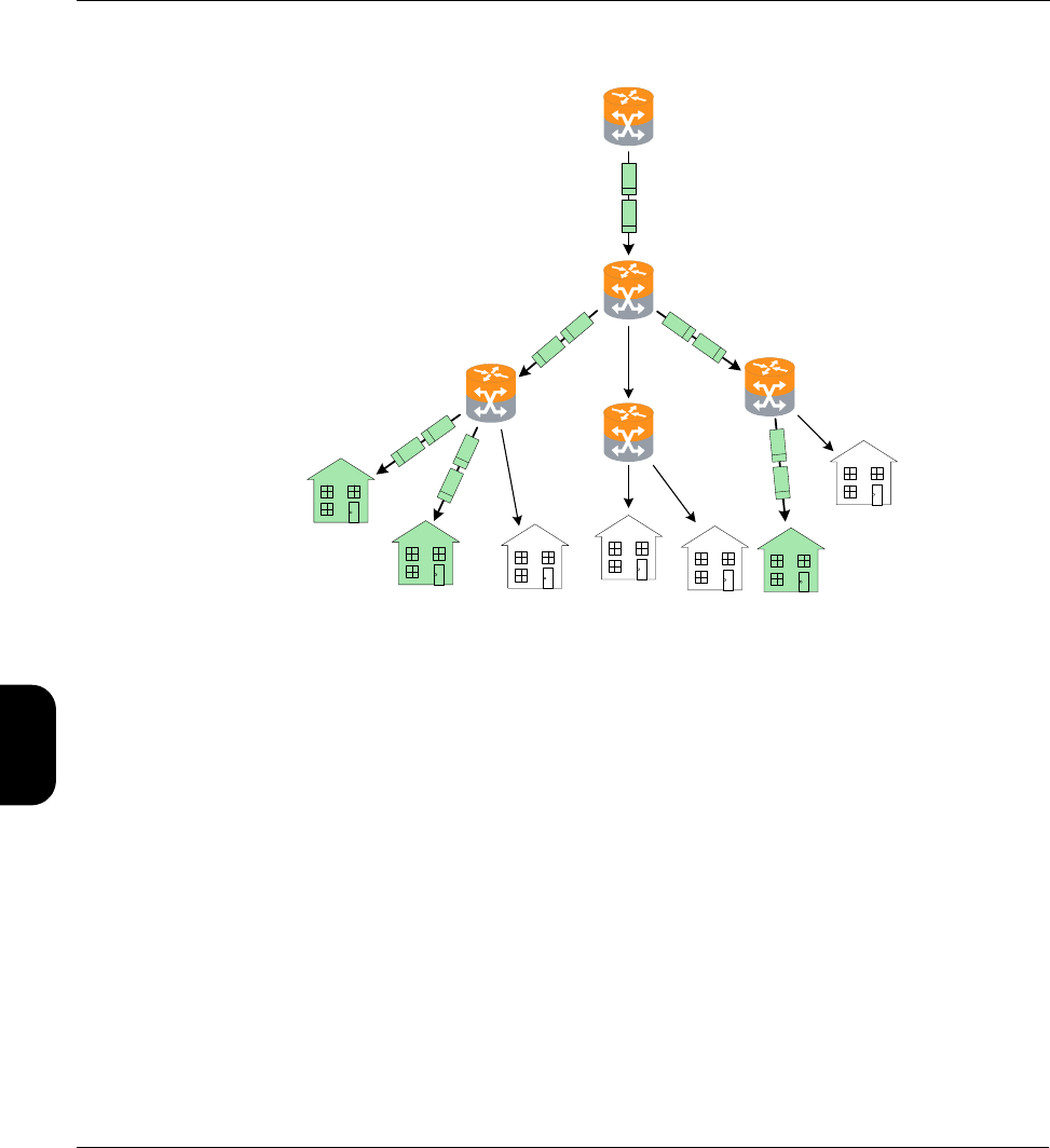
Verizon Base Unit User Guide Rev B PRELIMINARY 3/20/2014 Tech-X Flex® (P5)
5-36
Intro Wi-Fi 10/100 System IP/Video Specs
Figure 5-16 Hypothetical multicast network with multicasting and IGMP
In this example, the routers are multicast-aware and can make intelligent decisions about packet
forwarding. The routers control the forwarding of multicast packets, with those routers directly connected
to multicast group members using Internet Group Management Protocol (IGMP) to manage the
duplication and forwarding of packets to individual group members.
In a multicast-enabled network, multicast routers interact and dynamically maintain a logical tree for
routing multicast packets, in order to efficiently deliver the required packets to each subnet that requests
them. If no subscribers on a particular subnet are members of a given multicast group (for example, no
one on a particular subnet is viewing a particular audio/video stream), the network may automatically
adjust to avoid multicasting that stream to that subnet. Similarly, when a host on a subnet successfully
joins a group, the network will dynamically extend a branch of the respective multicast tree to the router
serving the host. In summary, therefore, multicasting improves transport efficiency both by eliminating
redundant packets from the same media source, and by eliminating the indiscriminate broadcast of any
packets to branches in the network that have no hosts requesting them.
Note that multicasting is a form of “selective broadcasting,” where packets from the source are simply
duplicated as necessary and forwarded onto the respective links, all the way down the multicast tree to
each requesting group member. IP multicast routers use specialized multicast routing protocols such as
R2
R3
R1
R4
R5

Tech-X Flex® (P5) Verizon Base Unit User Guide Rev B PRELIMINARY 3/20/2014
5-37
Intro
Wi-Fi
10/100
System
IP/Video
Specs
Protocol Independent Multicast (PIM) to build logical multicast trees and forward packets efficiently
between the multicast source and group members. Once multicast packets reach their destination
subnets, group members "listening" for packets with the specific IP multicast (destination) address will
receive and process the packets accordingly.
The IP address range of 224.0.0.0 - 239.255.255.255 is reserved for multicast packets. It should be
noted that these addresses are likely unroutable in a traditional sense on the destination subnets that
receive the packets. Rather, it is the suite of multicasting protocols that allows packets to be properly
forwarded and ultimately processed by the proper group member device(s). This is distinctly different
from unicast transmission, where IP packets are addressed for a specific source/destination pair and
exchanged exclusively between the two hosts.
Video quality measurement (VQM) overview and additional results descriptions
The following sections describe the quality measurement process in more detail; that is, the “VQM” mode
of analysis. For more information on MDI, see MDI measurement overview on page 5-40.
How the analysis works - An overview
The following metrics may be used to estimate the overall subjective quality of the audio/video stream,
some of which are also reported in the results:
•Audio/video packet details - Comprehensive metrics describing the number of MPEG packets
received, lost, and discarded.
•General audio/video stream information - Stream characteristics such as audio/video codec,
audio/video stream bit rate, video stream GOP size/structure, and video stream image size.
•Degradation factors - Identification and quantification of the factors which have caused degradation
of the video signal, such as codec, packet loss, and packets discarded due to buffer underrun and/or
overrun.
•General network metrics - Information on the overall packet transport network such as packet delay
variation and packet loss.
Quality is estimated based on general stream, packet, and frame characteristics that are known to have
a predictable impact on user experience. This methodology provides reliable measurements without the
need to decrypt a scrambled video signal. Packet loss is naturally the primary factor involved with
audio/video quality degradation, but the following types of considerations also affect quality calculations:
• Other problems related to network impairments, such as packet delay variation and out-of-sequence
packets.
• The inherent abilities of the codec and associated equipment to conceal network impairments such
as packet loss.

Verizon Base Unit User Guide Rev B PRELIMINARY 3/20/2014 Tech-X Flex® (P5)
5-38
Intro Wi-Fi 10/100 System IP/Video Specs
• The structure and length of GOPs (MPEG Groups of Pictures), especially with regards to the varied
effects of packet loss on different frame types.
• The bit rate and frame size (or resolution) used at the encoder, as smaller rates and lower resolutions
can degrade the quality of the image even if transport is flawless.
• The impact of recency. Recency is the trend of human viewers to judge audio/video quality to be
lower immediately following a disturbance to the signal, and the subsequent trend for that perception
to improve gradually if time passes with no further disturbance.
• Packet loss distribution. Bursty packet loss events in which consecutive packets are dropped have a
different effect on perceived audio/video quality than packet loss events in which single packets are
dropped and the time (or “distance”) between the single loss events is significant.
• Loss of synchronization between the audio and video signals.
While it does not measure signal-to-noise directly, the analysis does use codec and packet loss/discard
information to calculate an estimated peak signal/noise ratio (EPSNR). The EPSNR is then used as a
key input for quality score calculations.
About MOS and R-factor calculations
MOS (mean opinion score) is a numerical system used to grade the subjective perceptual quality of a
multimedia (audio, video, or both) user experience. Originally based on ITU-T recommendations for the
evaluation of voice quality, it uses a scale of 1 - 5 to indicate user experience with the following typical
benchmarks:
MOS scoring is frequently produced by software algorithms that monitor multimedia streams and attempt
to “emulate” a subjective user experience. Such software is intended to produce results that are similar to
MOS scores that would be recorded by actual human participants consuming and evaluating the media.
Score Quality Human perception of degradation
5Excellent Imperceptible. No degradation of quality can be detected
by a human subject.
4Good Perceptible. Degradation can detected, but does not
adversely impact the user experience.
3Fair Slightly annoying
2Poor Annoying
1Bad Very annoying or no data stream present

Tech-X Flex® (P5) Verizon Base Unit User Guide Rev B PRELIMINARY 3/20/2014
5-39
Intro
Wi-Fi
10/100
System
IP/Video
Specs
The R-factor is a similar concept and is actually the mathematical component by which a MOS is
estimated. It is calculated using what is known as the “E-model” formula. This formula involves a
subjective summation of impairment and “advantage” factors, including the typical packet network
parameters such as jitter, latency, and loss. Like the MOS score, the higher the number, the better. An R-
factor result is presented as a percentage, where 80% loosely corresponds with an MOS score of 4, and
a factor of 50% corresponds with an MOS of 2.6.
While these types of measurement may help you view a snapshot summary of network quality, you
should remember that “real,” quantifiable network conditions are the only reliable means of judging
network integrity. Any means of numerically calculating the quality of the human experience is
necessarily subjective.
About gap and burst states
The software models the distribution of packet loss over the measurement duration, which allows for a
more detailed characterization of the packet loss experienced by the audio/video stream. This is a four-
state model in which two periods of loss exist, gap and burst periods, each of which has two states.
The stream is considered to be in a gap condition of loss when consecutive packet loss is less than or
equal to one packet. If two or more consecutive packets are lost, the stream is considered to be in a burst
condition. Following the entry into a burst period, 128 consecutive packets must be received in order to
return to the gap condition, a number determined though research of quality measurements. Note that
the successfully received packets will be considered to have arrived during a gap period.
Other test results
About packet delay variation (PDV)
Packet delay variation is a calculation based on the variation of a packet’s expected arrival time versus
its actual arrival time. Each packet has its own PDV, which is determined by:
| Expected time - Arrival time |
...noting the use of absolute values. So, if a packet is expected to arrive at time1 but actually arrives at
time2, it has a PDV of | time1 - time2 |. Typically, individual PDVs are used for calculating an average for
multiple packets in a stream, or reporting the maximum PDV experienced during a measurement period.
NOTE: Packet delay variation is sometimes referred to as jitter. However, the use of PDV terminology
is preferred in this documentation due to its more specific definition.

Verizon Base Unit User Guide Rev B PRELIMINARY 3/20/2014 Tech-X Flex® (P5)
5-40
Intro Wi-Fi 10/100 System IP/Video Specs
About packet-to-packet delay variation (PPDV)
Packet-to-packet delay variation (PPDV) is a statistical calculation of delay variation, based on the
method described by the IETF RFC 3550. It differs from basic packet delay variation (PDV) which looks
at variations in arrival time overall, not necessarily variations between adjacent, sequential packets.
As an example, consider four sequential packets, whose delays in arrival are 40, 42, 38, and 39 msec
respectively. The delay variation of the second packet is 2 msec ( | 40 - 42 | ), the delay variation of the
third packet is 4 msec, and so forth. The measurements continue for all selected packets in the
measurement stream, with all measurements considered in the end for a calculation of statistical
variance.
Note that the usage of PDV versus PPDV is a complex subject and is beyond the scope of this
document.
MDI measurement overview
Media delivery index (MDI), defined by IETF RFC 4445
(http://www.ietf.org/rfc/rfc4445.txt?number=4445), is a technique for evaluating the quality of media
delivered over a packet-based network, including MPEG video. It focuses on the evaluation of delay
variation and packet loss, which are the primary network impairments that impact the delivery of
audio/video and other time-sensitive streaming media. In this respect, it is a packet-level, network-
focused type of evaluation, different from the type of subjective quality analysis that monitors stream
headers for specific transport characteristics. MDI may be used to evaluate voice, video, and other types
of streaming media.
An MDI result consists of two components: the Media Loss Rate (MLR) and the Delay Factor (DF),
typically presented as:
MLR:DF
Before analysis begins, the unit monitors the transport stream to determine the nominal media rate using
the Program Clock Reference (PCR). The unit then monitors the transport stream for the entire testing
interval to determine MLR and DF for that interval.
The MLR is the count of lost or out-of-order media packets over the measurement interval. Every MPEG
transport packet is counted, except for null packets (PID 0x1FFF) or packets with no payload. Note that a
single IP packet may contain multiple media packets, so a single IP packet loss event may cause a
significantly higher media loss.
Because the analysis is not coordinated with the encoding source, the unit cannot know what media
packets were actually sent. Therefore, it must determine lost packets using PID and continuity counter
values from transport stream headers. That is, when a packet arrives, lost packets can be interpolated
based on discrepancies between the current continuity counter and previous arrivals. Due to this method,

Tech-X Flex® (P5) Verizon Base Unit User Guide Rev B PRELIMINARY 3/20/2014
5-41
Intro
Wi-Fi
10/100
System
IP/Video
Specs
measured loss is only accurate when consecutive loss events are smaller than the capacity of the
continuity counter, which is 0-15 (4 bits). In other words, the maximum amount of measurable
consecutive loss is 15 packets. Also, note that a packet with an errored sync byte or a transport error
indicator set will be discarded and considered lost for the purpose of this measurement.
The unit also uses continuity counter values to determine out-of-order packets and the counter range of
0-15 provides a related accuracy limitation. The basic unit behavior is to consider any late packet that
arrives within 7 packets of expected order as out-of-order, otherwise it is considered to be a member of
the next counter “set.” This behavior is best illustrated by an example, as follows...
Assume that all packets are arriving as expected, when packet 2 of a counter set goes missing (that is,
packet 3 arrives after packet 1). At that point, packet 2 is initially considered lost. If packet 2 finally arrives
sometime before packet 9, its status changes to out-of-order and the respective cumulative counts are
adjusted accordingly. However, consider instead a scenario where packet 2 arrives after packet 10. In
this case, the original packet 2 is considered permanently lost and the packet that arrives is considered
to be packet 2 of the next set, at which point the originally-expected packets 11, 12, 13, 14, 15, 0, and 1
are initially considered lost. If these packets then arrive normally, their status changes to out-of-order and
the respective counts are adjusted accordingly. When the “real” packet 2 arrives for the next set, the unit
has two “packet 2’s” in the buffer and must assume that the original packet 2 is out-of-order for some
unknown previous set, so it increments the out-of-order count again and resets the algorithm. In this
scenario, a single late packet has caused the lost count to increment by one and the out-of-order count to
increment by 8.
The DF, presented as a quantity of time, is the maximum observed imbalance in stream flow over the
measurement interval, with respect to the expected media payload rate. That is, it effectively reports how
much buffering would be required to fully compensate for network delay variation at the respective node.
As such, it also indicates the amount of latency that must be introduced in order to properly decode the
stream. To calculate the DF, the software uses a “virtual buffer” concept, using the ingress of packets
versus the expected “drain” rate (that is, the media rate) to determine the variance. In some respects, the
DF provides a high-level view of the delay variation experienced by packets transiting from source to
destination. It may be useful to quantify the performance of the audio/video streams and transport
network over time and to adjust equipment buffers accordingly.
For convenience, Spirent has implemented a proprietary algorithm to convert MLR and DF calculations
into a score that resembles a mean opinion score (MOS), as defined by the ITU-T. This scoring method,
referred to as “MDI-S,” uses a scale of 1 - 5 to indicate perceived viewer experience with the following
typical benchmarks:
Score Quality Human perception of degradation
5Excellent Imperceptible. No degradation of video quality can be
detected by a human viewer.

Verizon Base Unit User Guide Rev B PRELIMINARY 3/20/2014 Tech-X Flex® (P5)
5-42
Intro Wi-Fi 10/100 System IP/Video Specs
Additional video testing notes
About the IP address specified for testing
The IP address specified must reflect the destination IP address for video stream packets; that is, the first
address contained in the IP packet headers. For a multicast stream, this will be a multicast IP address,
not an IP address of a host on the network under test. For a unicast stream, this must be the IP address
of the destination device on the network, such as a set-top box (STB).
About encrypted (scrambled) signals and frame type recognition
The analysis software does not perform any decryption of scrambled signals. For monitoring a scrambled
stream, this can affect the ability to recognize frame types because the type indicator data may be
encrypted as well. Because perceived effect of packet loss varies widely according to the type of frame
whose data was lost, the frame type is an important component when packet loss is evaluated. Therefore
the software exhibits the following behavior with regards to frame type recognition:
• If the signal is not scrambled, the software should be able to recognize frame types according to
explicit data in the stream and precisely associate lost packets with the respective type.
• If frame type data is encrypted but frame boundaries can be discerned, the software heuristically
attempts to determine frame type based on relative data size and expected patterns.
• If frames cannot determined at all, the software uses default GOP structure and length information
specified when the analysis is launched to interpolate the probabilities of packet loss occurring within
any given frame type. Over time, if the defaults accurately reflect the GOP setup of the stream, the
measurements and estimations should be statistically correct.
While the lack of decryption by the software may appear initially as a limitation, it actually provides much
more flexibility with deployment and ease of maintenance. With the ability to interpolate encrypted frame
types, users are not required to maintain and deploy decryption algorithms that require processing time,
change periodically, and may be expensive and/or difficult to license.
4Good Perceptible. Degradation can detected, but does not
adversely impact the viewing experience.
3Fair Slightly annoying
2Poor Annoying
1Bad Very annoying or no stream present
Score Quality Human perception of degradation
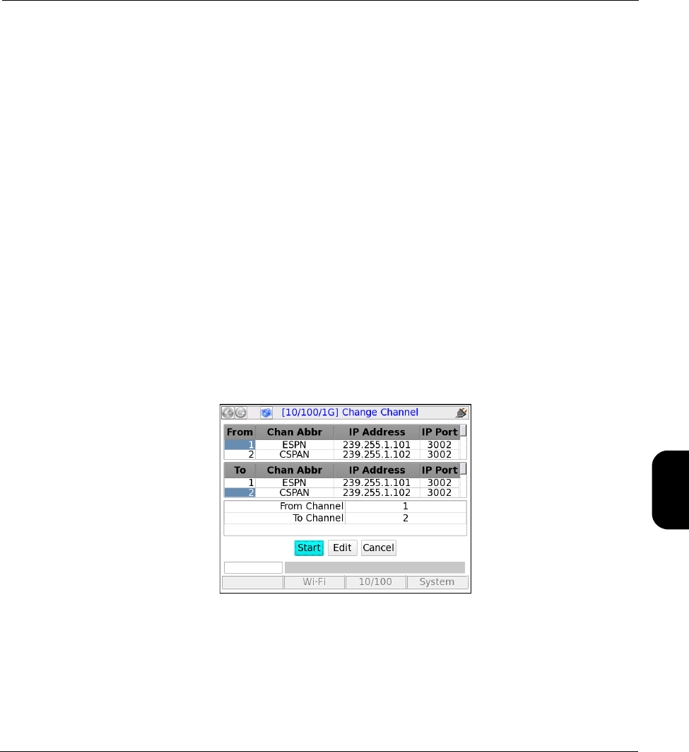
Tech-X Flex® (P5) Verizon Base Unit User Guide Rev B PRELIMINARY 3/20/2014
5-43
Intro
Wi-Fi
10/100
System
IP/Video
Specs
5.9.2 Change Channel
NOTE: Video testing is a purchasable option. Please contact Spirent for more information.
The IPTV change channel test measures channel change time by measuring the time between IGMP
requests and resulting changes in the packet stream. The unit accomplishes this measurement by joining
a multicast stream and initiating an actual channel change, emulating the behavior of IPTV subscriber
STB equipment.
For more detailed information on the time calculation, see How channel change time is calculated on
page 5-44.
Setup - Change Channel
The Change Channel setup differs whether or not a channel guide is active. For more information on
channel guides, see About channel guides on page 5-45.
With an active channel guide:
The unit presents a table with which you can select the two channels for the test. All other required
information is prepopulated from the channel guide, such as IP addresses and port numbers. For more
information on how the channels are used, see How channel change time is calculated on page 5-44.
Figure 5-17 Change Channel setup - Page 1 (with channel guide)
NOTE: The screen has a small display area and can only show a limited number of channels from the
guide at once. Remember to use the scroll bars on the table and/or the arrow keys on the key
pad to locate the desired channels. Furthermore, be sure that the From Channel and To
Channel at the bottom accurately reflect the channels you want to test.

Verizon Base Unit User Guide Rev B PRELIMINARY 3/20/2014 Tech-X Flex® (P5)
5-44
Intro Wi-Fi 10/100 System IP/Video Specs
Without an active channel guide:
The unit requires you to manually enter the following information for each channel:
•IP Address - IP address of the multicast stream
•IP Port - UDP or TCP port of the stream, with respect to the Encapsulation Method
•Encapsulation Method - Transport encapsulation used for the stream
•Codec - Video codec type
Results - Change Channel
The test reports the channel change time in msec, along with other parameters used in the calculation.
For more information, see How channel change time is calculated on page 5-44.
How channel change time is calculated
During a channel change test, the unit joins the first specified channel, leaves that channel, and then
joins the second specified channel. During this process, four key events are used for the change time
calculation, as illustrated in the following figure:
Figure 5-18 Channel change calculation timeline
Referring to this figure, if no time periods overlap, the basic formula for change time calculation is:
Time = (LastA - ML) + (FirstB - MJ)
ML
Multicast join
request - Ch. A
First packet -
Ch. A
Multicast leave
request - Ch. A
Last packet -
Ch. A
Multicast join
request - Ch. B
First packet -
Ch. B
LastA
MJ
FirstB
Time
Channel A stream Channel B stream

Tech-X Flex® (P5) Verizon Base Unit User Guide Rev B PRELIMINARY 3/20/2014
5-45
Intro
Wi-Fi
10/100
System
IP/Video
Specs
In these calculations, the individual terms are instances in time, not quantitative amounts of time. In other
words, channel change time equals time it takes to leave the first stream plus the time it takes to join the
second stream, measured from the respective IGMP requests.
For reference, the unit indicates the following test results:
•Leave to Last Time - Equals the (LastA - ML) term.
•Join To First Time - Equals the (FirstB - MJ) term.
5.9.3 Channel Guide Settings
This function allows you to configure the unit for channel guide usage. It is available from multiple menus
associated with active Video QoS testing, but the settings are global to all interfaces. For example, you
can access and configure these settings from the 10/100/1G menu, but all changes will also apply to
video testing on other interfaces, such as the modular MoCA interface. For more information about
channel guides, see About channel guides on page 5-45.
Table 5-22 Channel Guide Settings parameters
About channel guides
A channel guide provides a shortcut for specifying IP video channels during video testing of multicast
streams. When the unit joins and/or monitors a video stream for testing, it requires the IP address and
port of that stream. If you do not have an active channel guide on the unit, you must enter the address
and port manually. However, if you do have an active channel guide that includes the respective channel,
it allows you to select a simple channel number or a more intuitive channel abbreviation, such as CNN or
HBO. The unit then looks up the address and port in the guide instead of requiring a manual entry. A
Parameters Description
Use Channel Guide Indicates whether a channel guide is currently active for video test setup. For
more information, see About channel guides on page 5-45.
Guide Name Name of the active channel guide, only applicable when Use Channel
Guide=Yes. The drop-down list allows you to select from the guides currently on
the unit, if any. If the list is blank, no channel guides have been imported. For
more information, see About channel guides on page 5-45 and Download IPTV
Channel Guide on page 4-9.
Channel Format If Use Channel Guide=Yes, this setting determines how channels from the
guide are initially sorted in a video test setup screen, either by number or
abbreviation. In either case, the number or abbreviation comes directly from the
guide.

Verizon Base Unit User Guide Rev B PRELIMINARY 3/20/2014 Tech-X Flex® (P5)
5-46
Intro Wi-Fi 10/100 System IP/Video Specs
channel guide also provides a series of other default testing parameters for each channel, such codec
type and media stream information.
NOTE: The channel guide concept does not apply to unicast video. With unicast, the destination IP
address for video packets will be that of the endpoint device (such as an STB), rather than a
predictable multicast address. Therefore, it is not possible to standardize unicast IP information
within a channel guide.
Channel guides are in XML format and must adhere exactly to the format in the following sample (except
for the <!-- comments -->), with regard to tag names, case-sensitivity, and element hierarchy:
<video-channel-info>
<!-- Each channel is defined by a single <channel-info> element -->
<channel-info>
<!-- Channel number, an integer -->
<channel-number>001</channel-number>
<!-- Channel abbreviation, a string -->
<channel-abbreviation>ESPN</channel-abbreviation>
<!-- IP address of the channel stream in xxx.xxx.xxx.xxx format -->
<IP-address>239.255.1.101</IP-address>
<!-- UDP port of the stream, an integer -->
<IP-port>3002</IP-port>
<!-- Encapsulation type, UDP or RTP -->
<encapsulation>UDP</encapsulation>
<!-- Codec, H264, MPEG2, MPEG4, or NA -->
<codec>MPEG2</codec>
<!-- Jitter buffer mode, FIXED or ADAPTIVE -->
<jitter-mode>FIXED</jitter-mode>
<!-- GOP type, GOP_A, GOP_B, GOP_C, GOP_D, or GOP_E -->
<gop-type>GOP_C</gop-type>
<!-- GOP length, 1 - 100 -->
<gop-length>15</gop-length>
<!-- Loss sensitivity, -50 - 50 -->
<loss-sensitivity>0</loss-sensitivity>
<!-- Concealment level, 0 - 50 -->
<packet-loss-concealment-level>2</packet-loss-concealment-level>
<!-- Complexity (content coding factor), -50 - 50 -->
<image-complexity>0</image-complexity>
</channel-info>
<!-- ...additional <channel-info> elements, one for each channel -->
</video-channel-info>

Tech-X Flex® (P5) Verizon Base Unit User Guide Rev B PRELIMINARY 3/20/2014
5-47
Intro
Wi-Fi
10/100
System
IP/Video
Specs
The element names intuitively denote each respective parameter and the comments in the sample above
provide some description of valid values. To ensure that a channel guide conforms to the required
syntax, please contact Spirent for the latest XML schema and use it to validate your file(s).
Importing channel guides to the unit
See Download IPTV Channel Guide on page 4-9

Verizon Base Unit User Guide Rev B PRELIMINARY 3/20/2014 Tech-X Flex® (P5)
5-48
Intro Wi-Fi 10/100 System IP/Video Specs

Tech-X Flex® (P5) Verizon Base Unit User Guide Rev B PRELIMINARY 3/20/2014
6-1
6: Specifications
This section provides detailed information on physical components and specifications of the Tech-X Flex
base unit.
NOTE: Specifications are subject to change.
6.1 General specifications
Table 6-1 Physical specifications
Dimensions (H x W x D) • 8.964 in x 4.208 in x 2.524 in
• 22.77 cm x 10.69 cm x 6.41 cm
Weight 2.0 lb. (0.91 kg)
Display Color LCD with adjustable backlight. 480x640 pixels (VGA)
Case material BAYBLEND FR-3000 HI ABS + PC (POLYCARBONATE)
Rubber components TPU (DESMOPAN 9370A)
LED indicators Sync, Data, Errors, Charge
Communications
interfaces
• 10/100/1G Base-T Ethernet
• IEEE 802.11b/g/n/ac (“Wireless B”, “Wireless G”, “Wireless N”, and
“Wireless AC”) Wi-Fi
• USB 2.0
Test interfaces • 10/100/1G Base-T (x2)
• 802.11b/g/n/ac (wireless)

Verizon Base Unit User Guide Rev B PRELIMINARY 3/20/2014 Tech-X Flex® (P5)
6-2
Intro Wi-Fi 10/100 System IP/Video Specs
Table 6-2 Power specifications
Table 6-3 Environmental requirements
6.2 Wi-Fi specifications
Table 6-4 Wi-Fi specifications
6.3 FCC compliance statements
•RF exposure - This equipment complies with the FCC RF radiation exposure limits set forth for an
uncontrolled environment. For wireless 802.11b/g/n operation, the highest specific absorption rate
(SAR) value is 0.787 W/kg. Special considerations for 802.11ac transmission apply - see Important
wireless 802.11ac note on page 2-2.
•Co-location - This transmitter must not be co-located or operated in conjunction with any other
antenna or transmitter.
AC operations Requires external AC adapter/charger. Adapter will charge battery while
unit is in use. Adapter specifications:
•Input - 100 to 240 VAC, 50/60 Hz, 0.8 amps
•Output - 12 VDC, 2.0 amps
Battery type LiON rechargeable, replacements available from Spirent
Battery life 3-10 hours, depending on use and type of module attached
Battery recharge time 3-4 hours
Maximum power usage 24 watts
Maximum heat
dissipation
9 watts
Operating temperature -0.4 to 131°F (-18 to 55°C)
Storage temperature -4 to 158°F (-20 to 70°C)
Humidity tolerance 5 to 85% RH at +104°F (40°C)
Drop IEC 60068, 68-2-32
Protocol support 802.11b/g/n/ac with WEP, WPA, or WPA2 security
Antennas Two internal 802.11b/g/n antennas and three internal 802.11ac antennas

Tech-X Flex® (P5) Verizon Base Unit User Guide Rev B PRELIMINARY 3/20/2014
6-3
Intro
Wi-Fi
10/100
System
IP/Video
Specs
•Compliance - This device complies with Part 15 of FCC rules. Operation is subject to the following
two conditions:
1 This device may not cause harmful interference and,
2 This device must accept any interference received, including interference that may cause
undesired operation.
•Operation and installation - This equipment has been tested and found to comply with the limits for
a Class A digital device, pursuant to part 15 of the FCC Rules. These limits are designed to provide
reasonable protection against harmful interference when the equipment is operated in a commercial
environment. This equipment generates, uses, and can radiate radio frequency energy and, if not
installed and used in accordance with the manufacturer documentation, may cause harmful
interference to radio communications. Operation of this equipment in a residential area is likely to
cause harmful interference in which case the user will be required to correct the interference at his/
her own expense.
•Modifications - Changes or modifications not expressly approved by the party responsible for
compliance could void the user’s authority to operate the equipment.

Verizon Base Unit User Guide Rev B PRELIMINARY 3/20/2014 Tech-X Flex® (P5)
6-4
Intro Wi-Fi 10/100 System IP/Video Specs