Spotwave Wireless SPOTCELL0001 Indoor unit (SCU unit) User Manual SpotCell100
Spotwave Wireless Ltd. Indoor unit (SCU unit) SpotCell100
Contents
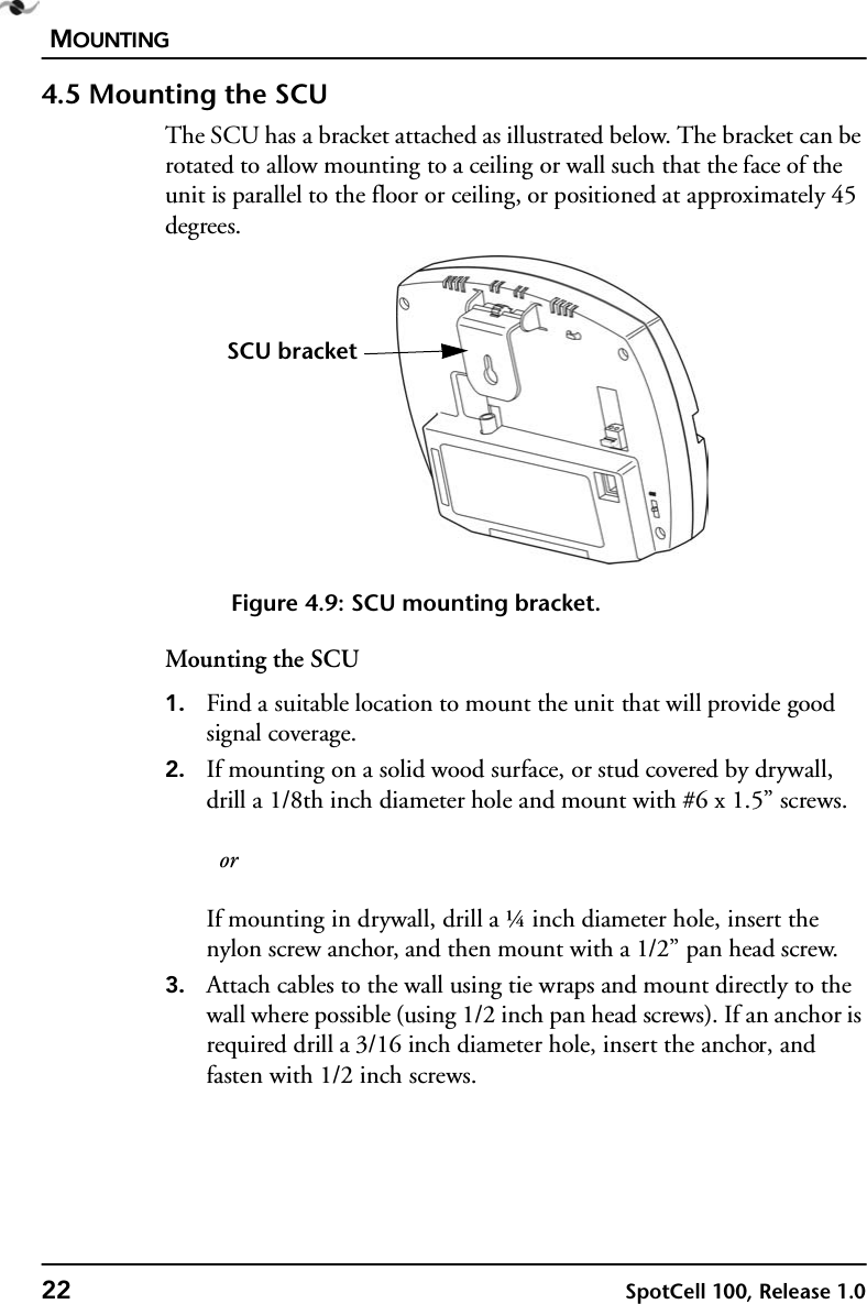
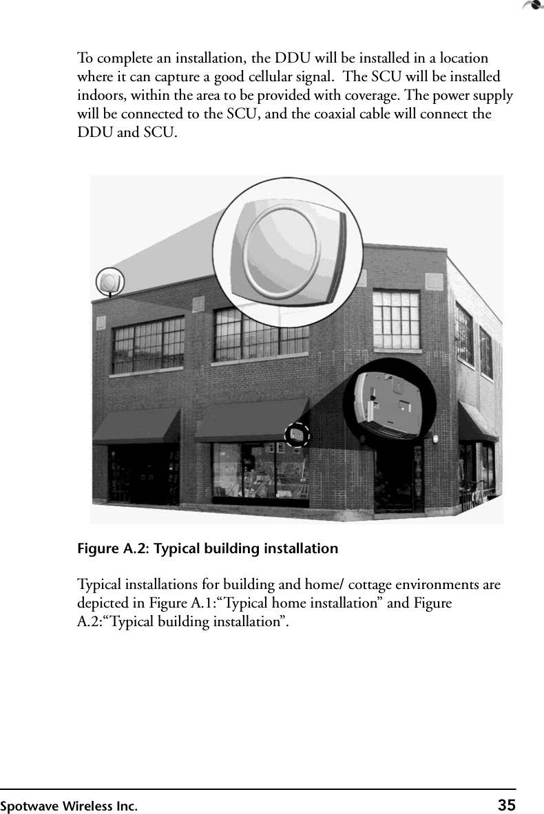
- 1. Installation manual
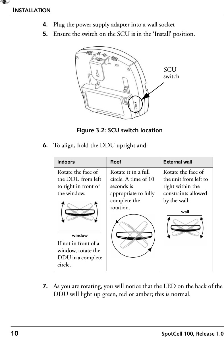
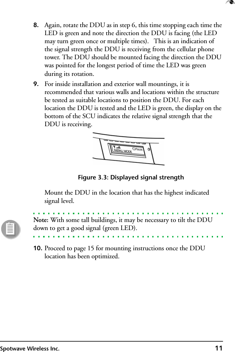
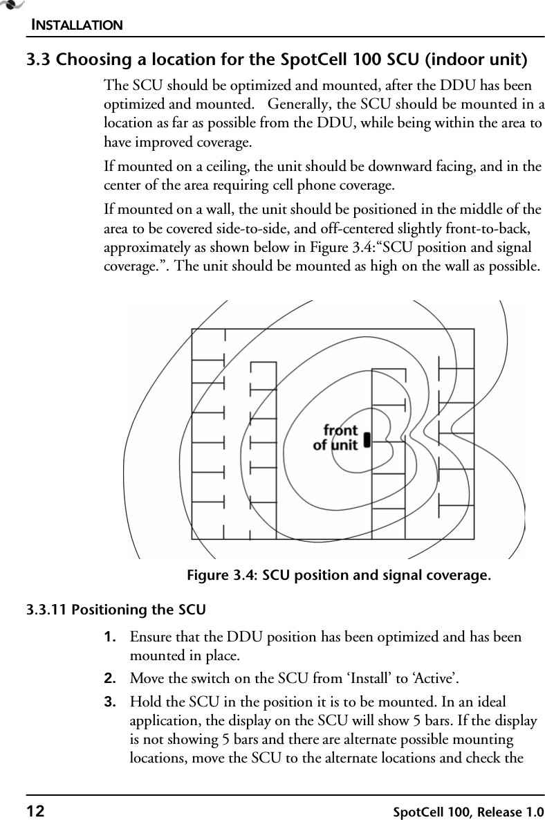
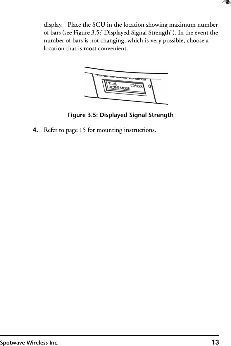
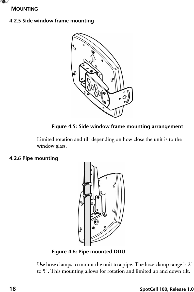
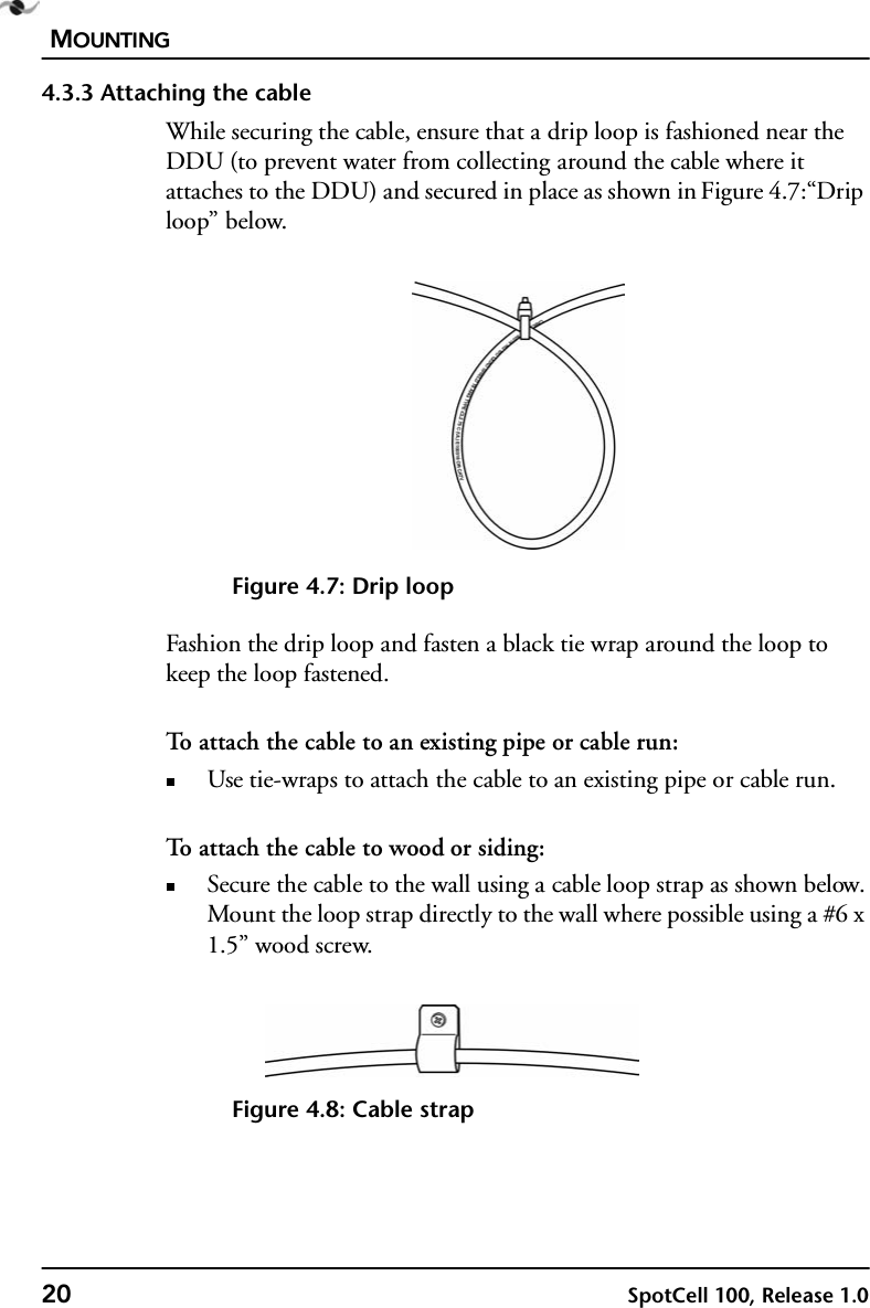
- 2. Users manual
- 3. Revised manual with safety notice
Revised manual with safety notice