Spotwave Wireless SPOTCELL0006 Spotcell 111/112 CU repeater User Manual SpotCell100
Spotwave Wireless Ltd. Spotcell 111/112 CU repeater SpotCell100
UserManual.wiki
>
Spotwave Wireless
>
SPOTCELL0006 User Manual
Users Manual
Navigation menu
Upload a User Manual
Namespaces
Wiki Guide
HTML
PDF
Info
Views
User Manual
Discussion / Help
Navigation

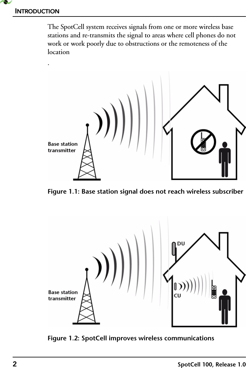

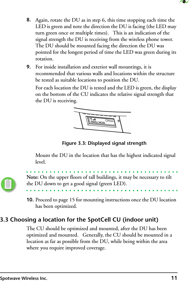
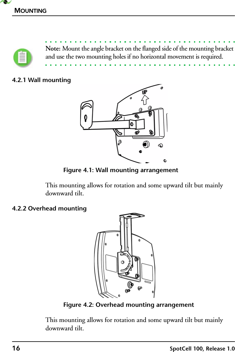
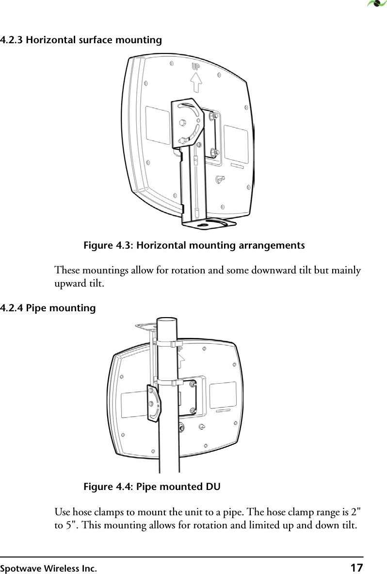
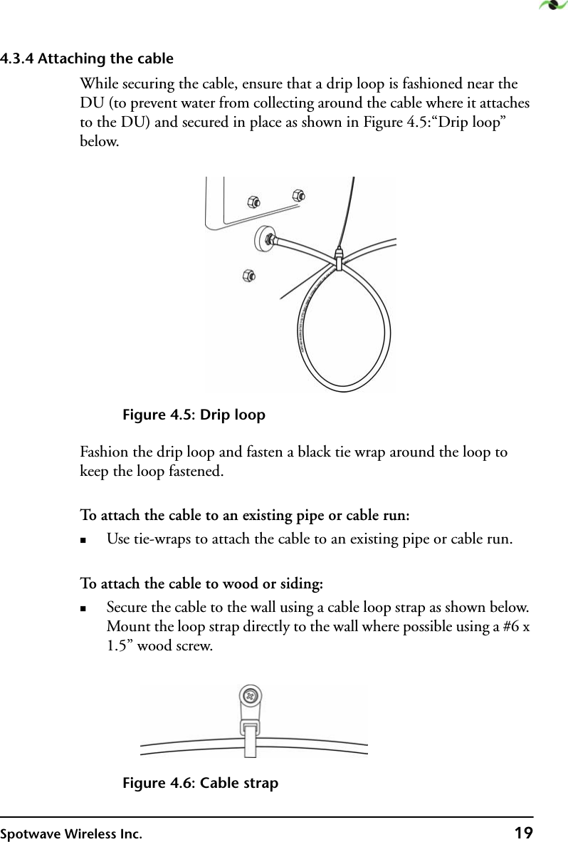

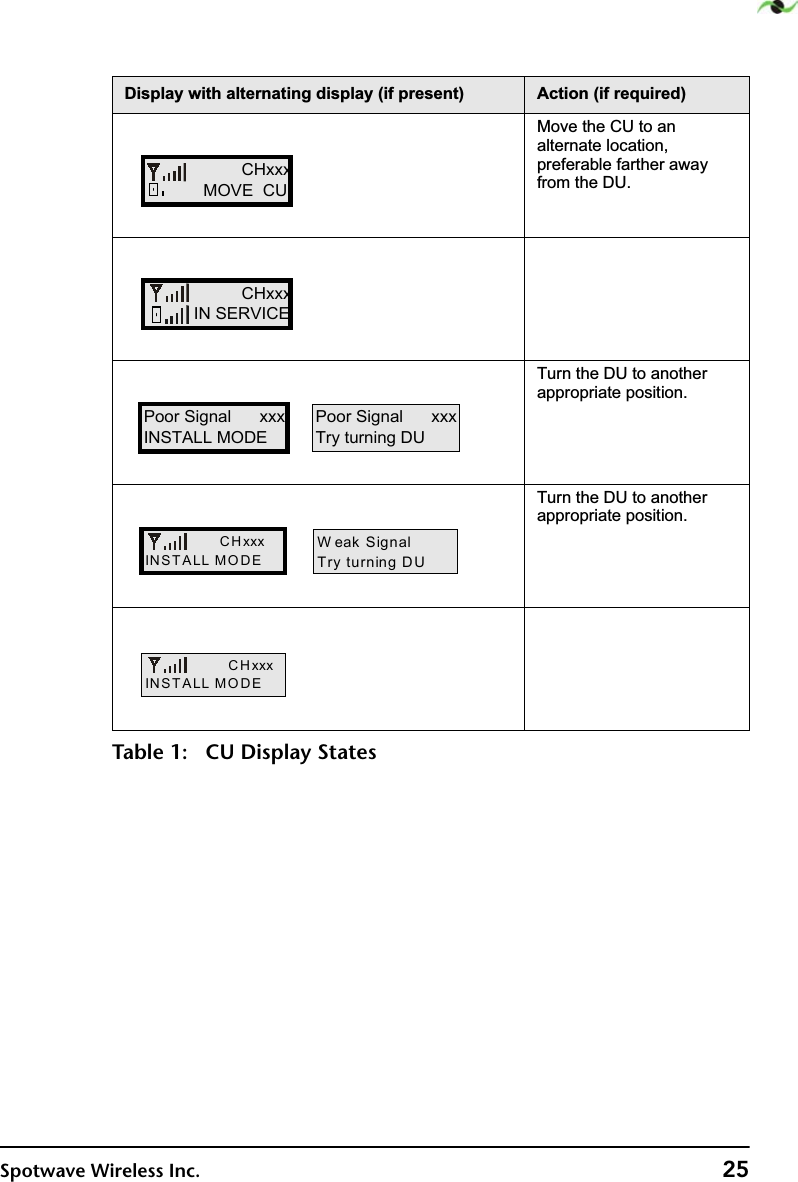
![DISPLAY INFORMATION24 SpotCell 100, Release 1.05.2 CUThe CU displays system status and signal strength. The following table shows the various messages displayed and if necessary, what action should be taken.'LVSOD\ZLWKDOWHUQDWLQJGLVSOD\LISUHVHQW $FWLRQLIUHTXLUHG,QLWLDOL]LQJ1RDFWLRQUHTXLUHG &KHFNWKH5)FDEOHDQGYHULI\WKDWLWLVFRQQHFWHGSURSHUO\0DNHVXUHWKHOHQJWKRIWKH5)FDEOHLVOHVVWKDQPHWHUV&DOOSURGXFWVXSSRUW7HOHSKRQH7KHVLJQDOPD\EHWRRZHDNRULQWHUIHUHGZLWKE\RWKHUVLJQDOV7XUQWKH'8WRDQRWKHUDSSURSULDWHSRVLWLRQ1RZLUHOHVVVLJQDOKDVEHHQIRXQGTable 1: CU Display StatesSpotwave W irelessV: xx DateSystem OKOUT OF SERVICESystem Fault xxxCHECK CABLECONNECTIONSCALL PRODUCTSUPPORTOUT OF SERVICESystem Fault xxxPoor Signal xxxTry turning DUPoor Signal xxxSearching . . . .](https://usermanual.wiki/Spotwave-Wireless/SPOTCELL0006/User-Guide-275559-Page-30.png)