Spotwave Wireless SPOTCELL0012 Cell enhancer User Manual SpotCell100
Spotwave Wireless Ltd. Cell enhancer SpotCell100
UserManual.wiki
>
Spotwave Wireless
>
SPOTCELL0012 User Manual
>
User guide
Contents
1.
User guide
2.
quick start guide
User guide
Navigation menu
Upload a User Manual
Namespaces
Wiki Guide
HTML
PDF
Info
Views
User Manual
Discussion / Help
Navigation


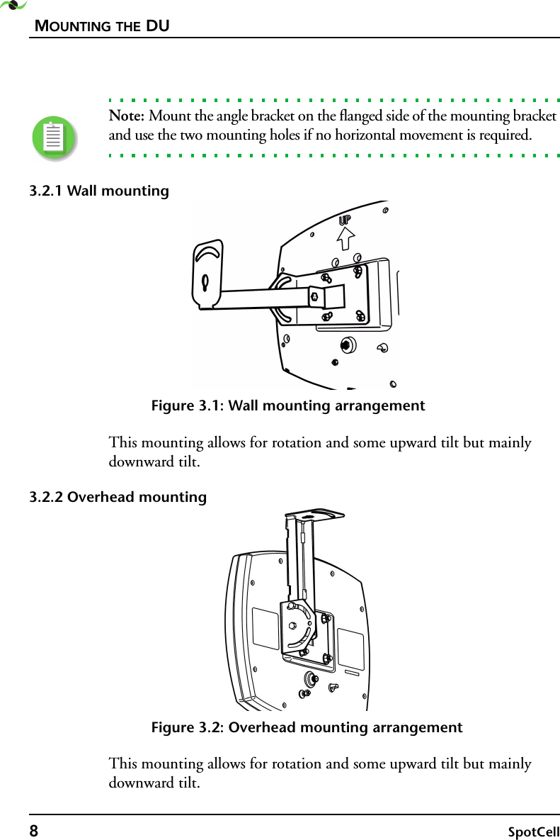
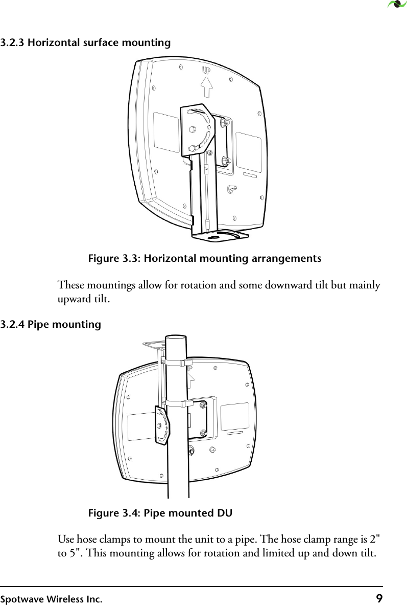
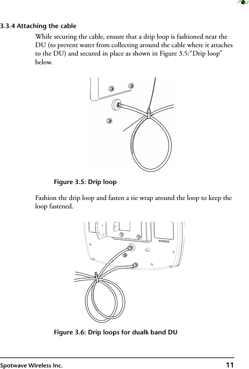
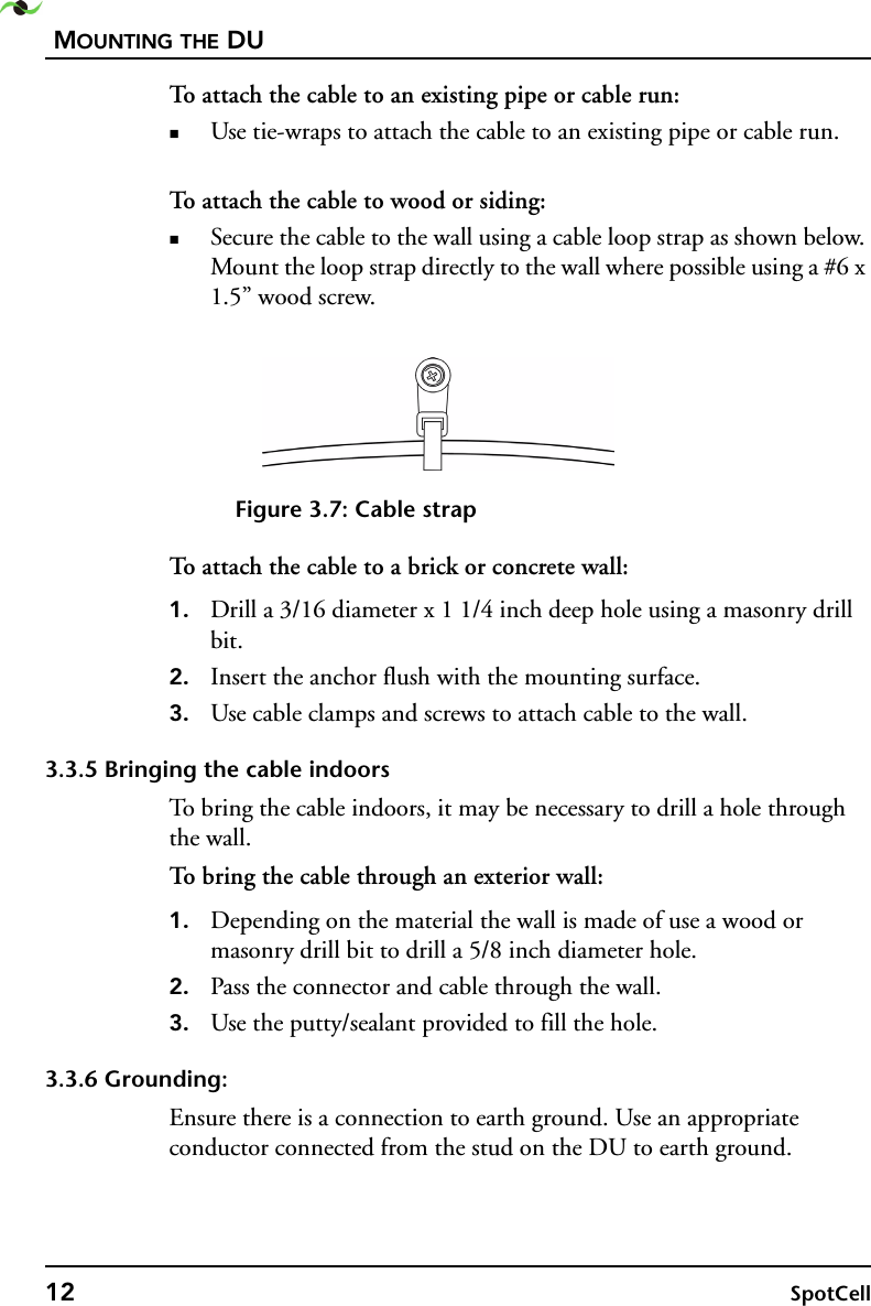
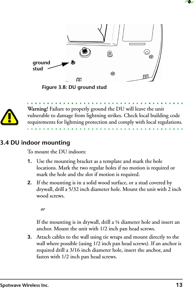

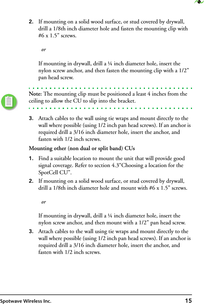
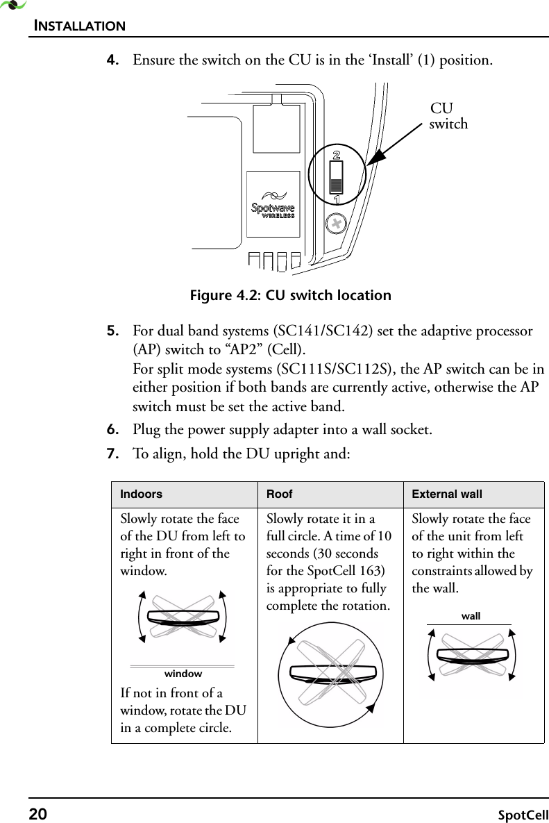
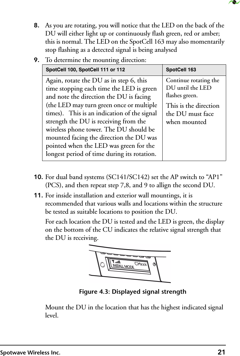
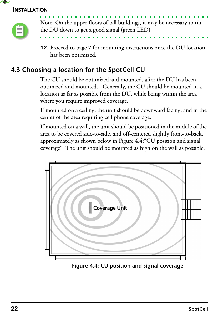
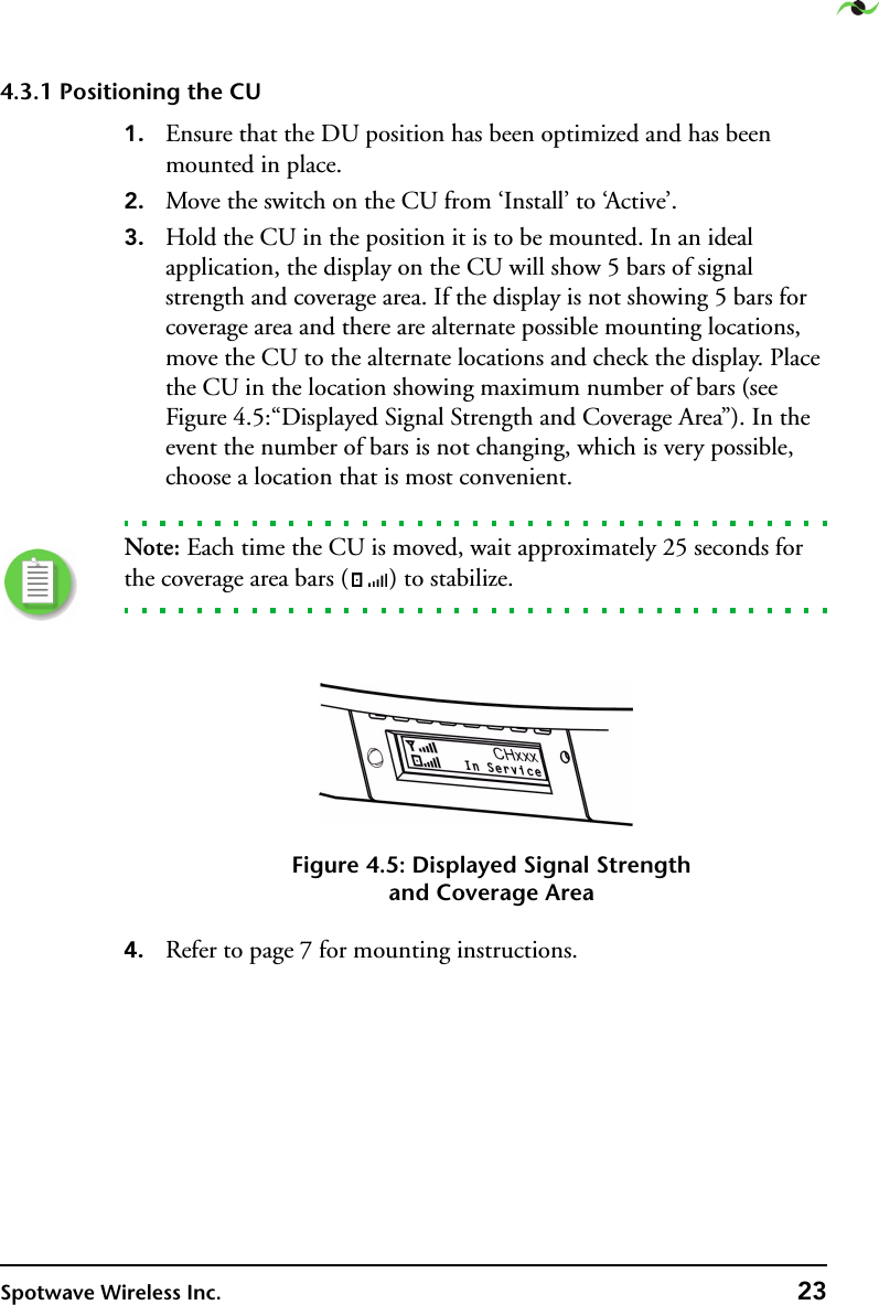
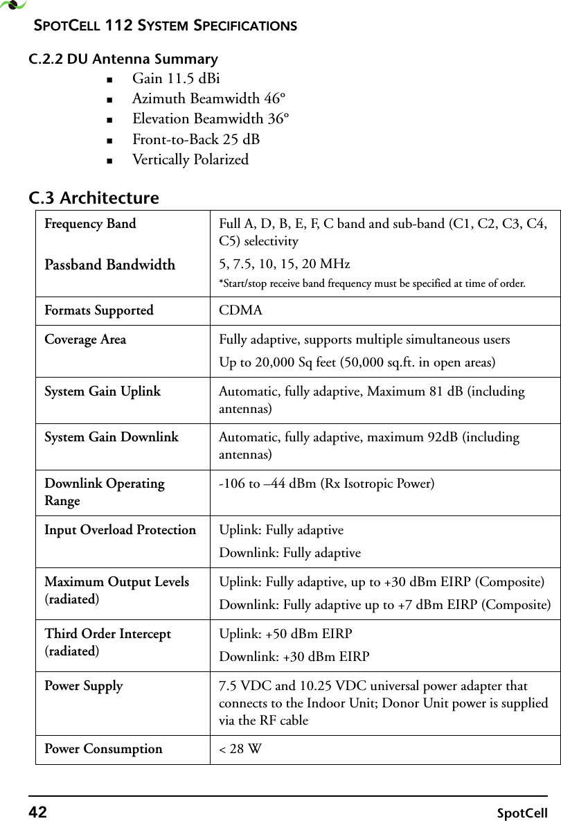
![SPOTCELL 100 SERIES SPECIFICATIONSSpotwave Wireless Inc. 35AC cable length: 6-ft DC cable length: 20-ft (both non-plenum)Downlink Operating Range-106 to -44-dBm (Rx Isotropic Power), coverage reduced below -92-dBmInput Over-load Protec-tionUplink: Fully adaptiveDownlink: Fully adaptiveOutput Lev-els (EIRP, composite radiated)Uplink: Fully adaptive, up to 30-dBm maximum.Downlink: Fully adap-tive, up to 7 dBm maxi-mum (managed per channel at -8 dBm/ch)Uplink: Fully adaptive, up to 30-dBm maximum.Downlink: Fully adap-tive, up to 7 dBm maxi-mum (managed per channel at 0 dBm/ch)Uplink: Fully adaptive, up to 30-dBm maximum.Downlink: Fully adap-tive, up to 7 dBm maxi-mum (managed per channel at 0 dBm/ch)Third Order Intercept (EIRP radi-ated)Uplink: 52-dBmDownlink: 30-dBmUplink: 52-dBmDownlink: 30-dBmUplink: 50-dBm Downlink: 30-dBmPower Supply AC Input Voltage: 100-V to 240-V 50/60-Hz DC Output Voltage: 7.5-V DC (1.8-A) and 10.25-V DC (1.0-A)Power Consumption: < 28-WCSA approved power adapter c/w 6-ft non-plenum AC cable and 20-ft non-plenum DC cable. DC cable connects to CU. DU powered from CU by interconnecting RF cable. AC cable length: 6-ft (non-plenum) DC cable length: 20-ft (non-plenum)* System Gain includes antenna gains and cable loss [82-ft of RG-6 or 164-ft of RG-11 (non-plenum rated)]. Note: longer cable lengths or plenum cable can often be accommodated with no coverage penalty.](https://usermanual.wiki/Spotwave-Wireless/SPOTCELL0012.User-guide/User-Guide-485201-Page-41.png)