Spotwave Wireless SPOTCELL0012 Cell enhancer User Manual SpotCell 11x QuickStart 14Sep04
Spotwave Wireless Ltd. Cell enhancer SpotCell 11x QuickStart 14Sep04
UserManual.wiki
>
Spotwave Wireless
>
SPOTCELL0012 User Manual
>
quick start guide
Contents
1.
User guide
2.
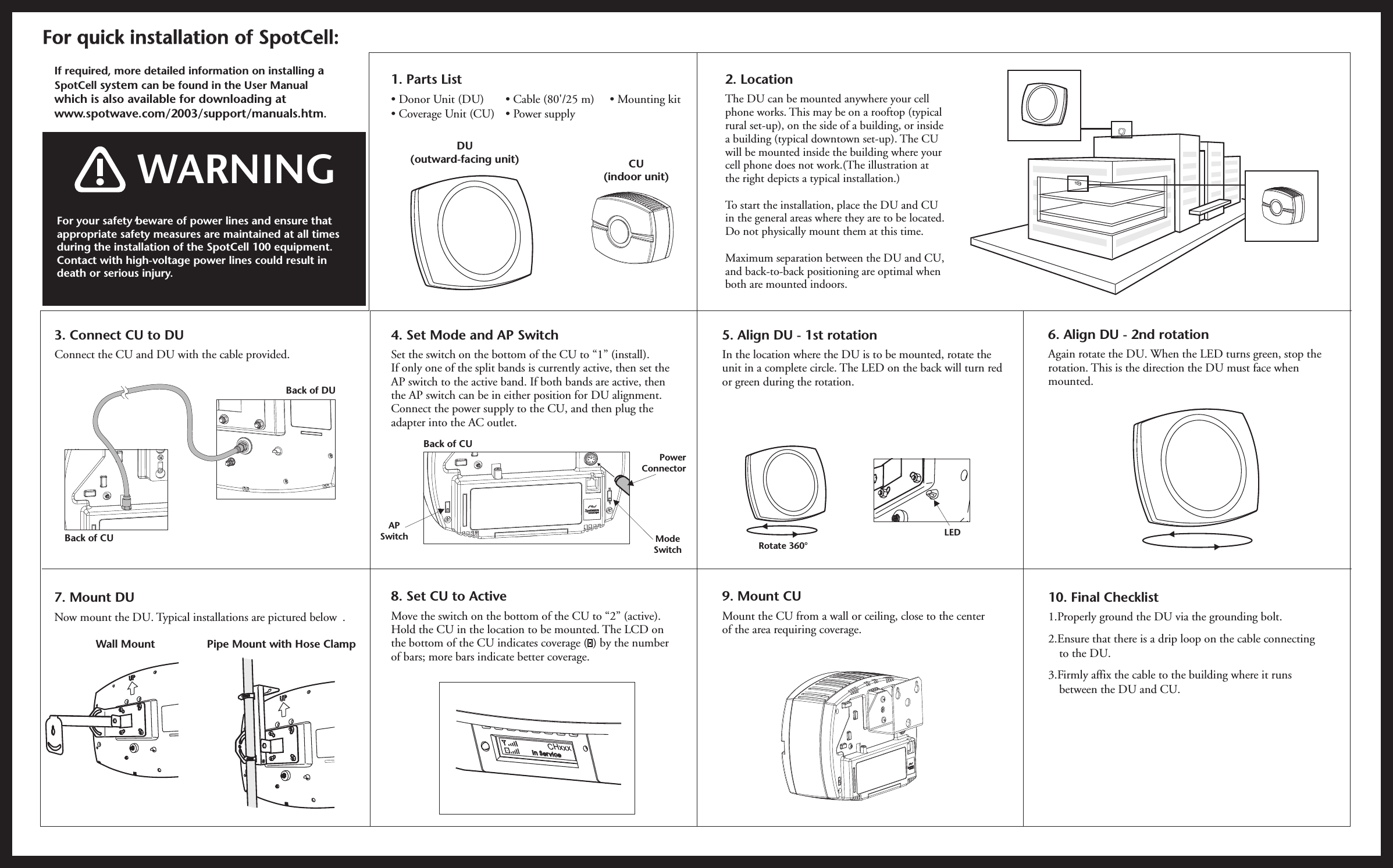
quick start guide
quick start guide
Navigation menu
Upload a User Manual
Namespaces
Wiki Guide
HTML
PDF
Info
Views
User Manual
Discussion / Help
Navigation