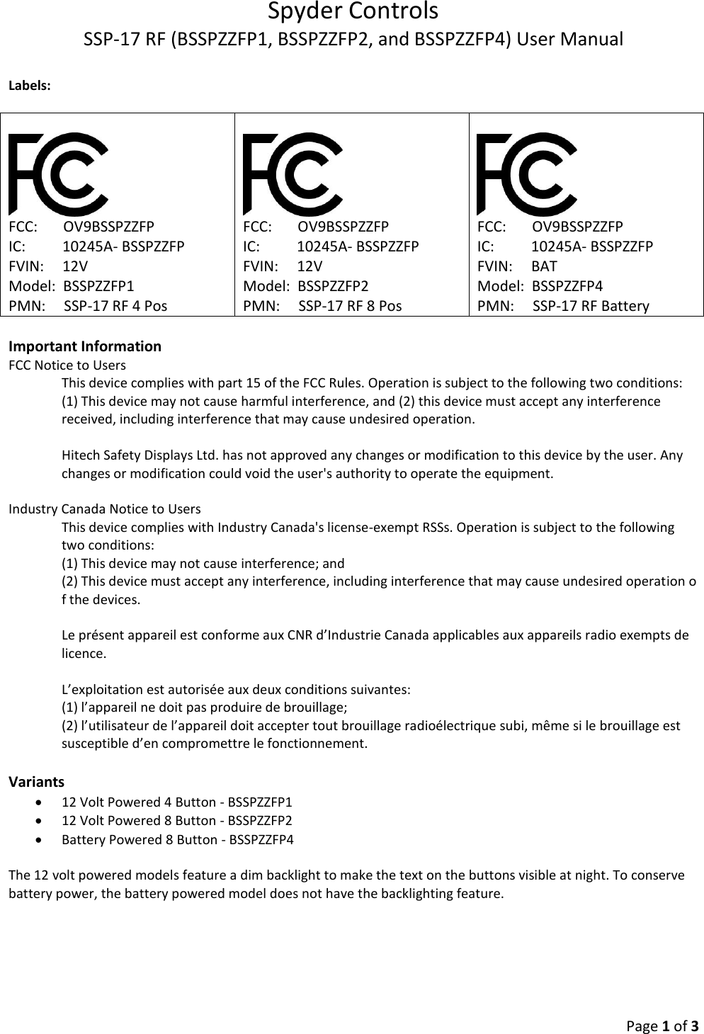
Spyder Controls BSSPZZFP Momentary operation remote control User Manual

Spyder Controls Corp. Momentary operation remote control

User Manual

Spyder Controls SSP-17 RF (BSSPZZFP1, BSSPZZFP2, and BSSPZZFP4) User Manual   Page 1 of 3  Labels:      FCC:       OV9BSSPZZFP IC:          10245A- BSSPZZFP FVIN:     12V Model:  BSSPZZFP1 PMN:     SSP-17 RF 4 Pos      FCC:       OV9BSSPZZFP IC:          10245A- BSSPZZFP FVIN:     12V Model:  BSSPZZFP2 PMN:     SSP-17 RF 8 Pos      FCC:       OV9BSSPZZFP IC:          10245A- BSSPZZFP FVIN:     BAT Model:  BSSPZZFP4 PMN:     SSP-17 RF Battery  Important Information FCC Notice to Users This device complies with part 15 of the FCC Rules. Operation is subject to the following two conditions: (1) This device may not cause harmful interference, and (2) this device must accept any interference received, including interference that may cause undesired operation.   Hitech Safety Displays Ltd. has not approved any changes or modification to this device by the user. Any changes or modification could void the user's authority to operate the equipment.   Industry Canada Notice to Users This device complies with Industry Canada's license-exempt RSSs. Operation is subject to the following two conditions:  (1) This device may not cause interference; and  (2) This device must accept any interference, including interference that may cause undesired operation o  f the devices.   Le présent appareil est conforme aux CNR d’Industrie Canada applicables aux appareils radio exempts de licence.   L’exploitation est autorisée aux deux conditions suivantes:  (1) l’appareil ne doit pas produire de brouillage;  (2) l’utilisateur de l’appareil doit accepter tout brouillage radioélectrique subi, même si le brouillage est susceptible d’en compromettre le fonctionnement.  Variants  12 Volt Powered 4 Button - BSSPZZFP1  12 Volt Powered 8 Button - BSSPZZFP2  Battery Powered 8 Button - BSSPZZFP4  The 12 volt powered models feature a dim backlight to make the text on the buttons visible at night. To conserve battery power, the battery powered model does not have the backlighting feature.
Spyder Controls SSP-17 RF (BSSPZZFP1, BSSPZZFP2, and BSSPZZFP4) User Manual   Page 2 of 3  Operation   The SSP-17 RF switch panel features an integrated 400 Mhz Transmitter that wirelessly sends messages to a reciever device. Each switch panel has a green “Transmit LED” located at the bottom center. This LED should turn on whenever a button is being pressed or held indicating that the switch panel is transmitting. The LED will also flash briefly once every 20 seconds when it transmitts the battery status and/or the optional ambient temperature data.   The messages sent out by each switch panel has a unique identifier which is used to distinguish them from one another. The message sent out when pressing a button also indicates which button is being pressed to allow the reciving device to perform a unique action for each button. The wireless reciever device only acnologes messages from switch panels that are paired with it. To pair a switch panel with the receiving device, put the reciviving device into pairing mode (folowing the instructions for the reciever device), then press any two butons on the switch panel simultaneously to send a pairing signal.  Not Transmitting      Transmitting     Transmit LED
Spyder Controls SSP-17 RF (BSSPZZFP1, BSSPZZFP2, and BSSPZZFP4) User Manual   Page 3 of 3                                          12 Volt Powered    Battery Powered           Troubleshooting  If the switch panel is not operating as expected watch the Transmit LED and press on of the buttons to see if it comes on. If the LED does not come on, check the power source. For the battery powered version, replace the CR2032 battery and try operating the switch panel again. For the 12 volt version, verify that the red power wire has a good connection to ground and that the black wire has a good connection to ground. If the Transmit LED still does not turn on when pressing a button after troubleshooting the power source, the switch panel has failed and needs to be replaced.   If the switch panel does not operate as expected but the Transmit LED does come on when pressing the button there is likely a problem with the receer device. Refer to the document to the reciever device being used for troubleshooting and pairing procedures. Power Wire Ground Wire CR2032 Battery

Navigation menu