Standard Communications CM60UL25 UHF MOBILE TRANSCEIVER User Manual UM CM60 UserManual indb
Standard Communications Pty Ltd UHF MOBILE TRANSCEIVER UM CM60 UserManual indb
UserManual.wiki
>
Standard Communications
>
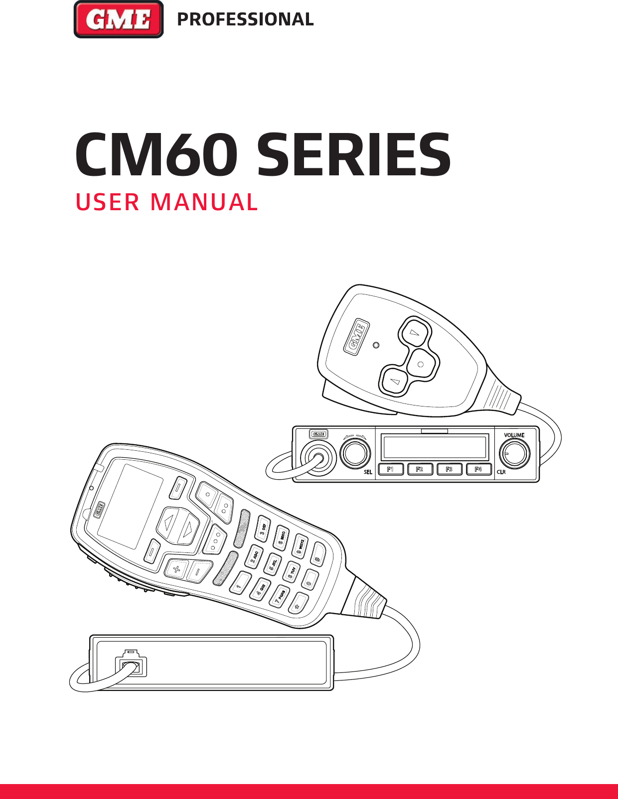
CM60UL25 User Manual
User Manual
Navigation menu
Upload a User Manual
Namespaces
Wiki Guide
HTML
PDF
Info
Views
User Manual
Discussion / Help
Navigation