Standard Communications CM60UL25 UHF MOBILE TRANSCEIVER User Manual UM CM60 UserManual indb
Standard Communications Pty Ltd UHF MOBILE TRANSCEIVER UM CM60 UserManual indb
User Manual
CM60 SERIES
USER MANUAL

CM60 Series User Manual
09 May 2018
© 2018 Standard Communicaons Pty Ltd. All rights reserved.
2
49809-4
Preface
Copyright Noce
Standard Communicaons Pty Ltd reserves all rights to this document and the informaon contained
herein. Reproducon, use or disclosure to third pares without the express permission is strictly
prohibited.
© 2018 Standard Communicaons Pty Ltd, Sydney, Australia
Radio Frequency Exposure Hazard
Aenon
This radio should be used only in an occupaonal (work related) environment where the user is
aware of and able to exercise control over their exposure to RF energy. This radio is not authorised
for use by the consumer or by the general populaon.
To comply with the US FCC radio frequency guidelines and to ensure your safety please read the
following informaon before installing and using the radio.
• Use the radio only within the guidelines of the manufacturer.
• Use only with an approved antenna.
• Ensure your antenna is installed as described under the ‘Installaon’ secon of the Service manual.
• Do not remove the RF Exposure label from this radio.
• Do not transmit longer than the rated duty cycle of 50% talk-50% listen.
Radio Frequency Exposure Control
This radio emits RF (Radio Frequency) energy or radio waves when transming. RF energy is one of
many forms of electromagnec energy including sunlight and electricity. The FCC Radio Frequency
exposure guidelines include recommendaons on the safe levels of exposure for workers and the
general public with a signicant margin of protecon.
It is important to follow the guidelines below to control your RF exposure, and comply with the
maximum exposure limits for occupaonal/controlled environments.
• Do not talk/transmit on the radio for longer than the rated duty cycle of 50% talk -50%
listen. This is because the radio emits more energy when it is transming than when it is
receiving.
• Ensure that you maintain a safe distance of 35 inches (0.9 m) between people and the
antenna when you are talking or sending informaon on the radio.
• Use only GME-approved antennas and aachments with the radio.
• Ensure that you make only authorized modicaons to the antennae to avoid damaging
the radio and violang FCC regulaons.

CM60 Series User Manual
09 May 2018
© 2018 Standard Communicaons Pty Ltd. All rights reserved.
3
49809-4
Preface
Compliance with RF Energy Standards
This radio is designed and tested to comply with a number of naonal and internaonal standards
and guidelines (listed below) regarding human exposure to RF electromagnec energy. This
radio complies with the IEEE and ICNIRP exposure limits for occupaonal/controlled RF exposure
environment at duty cycles of up to 50% talk-50% listen and should be used for occupaonal use
only. In terms of measuring RF energy for compliance with the FCC exposure guidelines, your radio
radiates measurable RF energy only when it is transming (during talking), not when it is receiving
(listening) or in standby mode.
This radio complies with the following RF energy exposure standards and guidelines:
• United States Federal Communicaons Commission, Code of Federal Regulaons; 47CFR
part 2 sub-part J
• American Naonal Standards Instute (ANSI)/Instute of Electrical and Electronic
Engineers (IEEE) C95. 1-1992
• Instute of Electrical and Electronic Engineers (IEEE) C95. 1-1999 edion
• Internaonal Commission on Non-Ionizing Radiaon Protecon (ICNIRP) 1998
FCC Compliance
To comply with FCC exposure limits the radio must be installed using an externally mounted antenna
with a gain of either 2.15 dBi or 5.15 dBi. The antenna must be mounted centrally on the roof of
the vehicle in a locaon that ensures a minimum safe distance as stated in the FCC Uncontrolled RF
Exposure Limits table in this secon.
For further informaon on RF energy exposure and how to control it, please visit the following
website: hps://www.fcc.gov/engineering-technology/electromagnec-compability-division/
radio-frequency-safety/faq/rf-safety
This equipment has been tested and found to comply with the limits for a Class B digital device,
pursuant to part 15 of the FCC Rules. These limits are designed to provide reasonable protecon
against harmful interference in a residenal installaon. This equipment generates uses and can
radiate radio frequency energy and, if not installed and used in accordance with the instrucons,
may cause harmful interference to radio communicaons. However, there is no guarantee that
interference will not occur in a parcular installaon. If this equipment does cause harmful
interference to radio or television recepon, which can be determined by turning the equipment
o and on, the user is encouraged to try to correct the interference by one or more of the following
measures:
• Reorient or relocate the receiving antenna.
• Increase the separaon between the equipment and receiver.
• Connect the equipment into an outlet on a circuit dierent from that to which the
receiver is connected.
Consult the dealer or an experienced radio/TV technician for help.
This device complies with part 15 of the FCC rules. Operaon is subject to the following two
condions:
• This device may not cause harmful interference, and
• This device must accept any interference received, including interference that may cause

CM60 Series User Manual
09 May 2018
© 2018 Standard Communicaons Pty Ltd. All rights reserved.
4
49809-4
Preface
undesired operaon.
Note: The grantee is not responsible for any changes or modicaons not expressly approved by the
party responsible for compliance. Such modicaons could void the user’s authority to operate the
equipment.
FCC Uncontrolled RF Exposure Limits
Model 2.15 dBi Antenna 5.15 dBi Antenna
VHF 0.903 m 1.276 m
UHF L, UHF 0.738 m 1.042 m
IC RSS Compliance
• For license-exempt devices:
This device complies with Industry Canada license-exempt RSS standard(s). Operaon is
subject to the following two condions:
• This device may not cause interference, and
• This device must accept any interference, including interference that may cause
undesired operaon of the device.
• (French)
Le présent appareil est conforme aux CNR d’Industrie Canada applicables aux appareils
radio exempts de licence. L’exploitaon est autorisée aux deux condions suivantes:
• l’appareil ne doit pas produire de brouillage, et
• l’ulisateur de l’appareil doit accepter tout brouillage radioélectrique subi, même si
le brouillage est suscepble d’en compromere le fonconnement.
• For transmiers w/ detachable antennas:
This radio transmier has been approved by Industry Canada to operate with the
antenna types listed below with the maximum permissible gain and required antenna
impedance for each antenna type indicated. Antenna types not included in this list,
having a gain greater than the maximum gain indicated for that type, are strictly
prohibited for use with this device.
• (French)
Le présent émeeur radio a été approuvé par Industrie Canada pour fonconner
avec les types d’antenne énumérés ci-dessous et ayant un gain admissible maximal et
l’impédance requise pour chaque type d’antenne. Les types d’antenne non inclus dans
cee liste, ou dont le gain est supérieur au gain maximal indiqué, sont strictement
interdits pour l’exploitaon de l’émeeur.
IC Uncontrolled RF Exposure Limits
Model 2.15 dBi Antenna 50 Ω 5.15 dBi Antenna 50 Ω
VHF 1.124 m 1.588 m
UHF L,
UHF
0.966 m 1.364 m
For detailed informaon about RF energy, and how to control exposure to it, refer the following IC
website: hp://www.ic.gc.ca/eic/site/smt-gst.nsf/eng/sf08792.html

CM60 Series User Manual
09 May 2018
© 2018 Standard Communicaons Pty Ltd. All rights reserved.
5
49809-4
Preface
Interference with Vehicle Electronics
Some of the electronics in your vehicle may be suscepble to RF energy when your radio is
transming. Examples of electronic devices in your vehicle that could be aected are an-lock/an-
skid braking systems, cruise control systems and fuel injecon systems. If your vehicle is ed with
any of these systems please consult your vehicle manufacturer to determine whether these systems
are likely to be aected by your radio when it is transming. Careful selecon of mounng locaons
and good installaon techniques should generally minimise any interference to your vehicle
electronics.
Using the Radio in Explosive Atmospheres or Blasng Areas
Switch o your radio before entering any area where there may be inammable gas, liquids or dust.
An explosion could result in serious injury or death.
Switch o your radio when approaching a blasng area. Blasng areas are usually sign posted with
instrucons to users to turn o two way radios. Strong radio transmissions could ignite blasng caps
resulng in an unscheduled explosion resulng in serious injury or death.
Installaon Guidelines
• Do not install the radio near an airbag or in an area where an airbag may deploy. If an
airbag is obstructed by the radio, it may not deploy as expected. It could also propel the
radio with enough force to cause serious injury.
• Avoid touching the heat sink at the rear of the radio while the radio is in use. The heat
sink can become hot during prolonged use.
• Do not install the radio in front of a vehicle heater. The radio requires a cool airow over
the rear heat sink when transming to maintain eciency.
• Do not make unapproved modicaons to the radio. Such modicaons could void the
warranty and cause the radio to operate outside its approved specicaons.
Warranty
This warranty against defects is given by Standard Communicaons Pty Ltd ACN 000 346 814 (We,
us, our or GME). Our contact details are set out in clause 2.h.
1. Consumer guarantees:
a. Our goods come with guarantees that cannot be excluded under the Australian
Consumer Law. You are entled to a replacement or refund for a major failure and
for compensaon for any other reasonably foreseeable loss or damage. You are also
entled to have the goods repaired or replaced if the goods fail to be of acceptable
quality and the failure does not amount to a major failure.
b. To the extent we are able, we exclude all other condions, warranes and
obligaons which would otherwise be implied.
2. Warranty against defects:
a. This warranty is in addion to and does not limit, exclude or restrict your rights

CM60 Series User Manual
09 May 2018
© 2018 Standard Communicaons Pty Ltd. All rights reserved.
6
49809-4
Preface
under the Compeon and Consumer Act 2010 (Australia) or any other mandatory
protecon laws that may apply.
b. We warrant our goods to be free from defects in materials and workmanship for
the warranty period from the date of original sale (or another period we agree
to in wring). Subject to our obligaons under clause 1.2, we will at our opon,
either repair or replace goods which we are sased are defecve. We warrant any
replacement parts for the remainder of the period of warranty for the goods into
which they are incorporated.
c. To the extent permied by law, our sole liability for breach of a condion, warranty
or other obligaon implied by law is limited
in the case of goods we supply, to any one of the following as we decide –
(i) the replacement of the goods or the supply of equivalent goods;
(ii) the repair of the goods;
(iii) the cost of repairing the goods or of acquiring equivalent goods;
d. in the case of services we supply, to any one of the following as we decide –
(i) the supplying of the services again;
(ii) the cost of having the services supplied again.
e. For repairs outside the warranty period, we warrant our repairs to be free from
defects in materials and workmanship for three months from the date of the original
repair. We agree to repair or replace (at our opon) any materials or workmanship
which we are sased are defecve.
f. We warrant that we will perform services with reasonable care and skill and agree
to invesgate any complaint regarding our services made in good faith. If we are
sased that the complaint is jused, and as our sole liability to you under this
warranty (to the extent permied at law), we agree to supply those services again at
no extra charge to you.
g. To make a warranty claim you must before the end of the applicable warranty period
(see warranty table), at your own cost, return the goods you allege are defecve,
provide wrien details of the defect, and give us an original or copy of the sales
invoice or some other evidence showing details of the transacon.
h. Send your claim to:
Standard Communicaons Pty Ltd.
PO Box 96 Winston Hills, NSW 2153, Australia.
Tel: (02) 8867 6000 Fax: (02) 8867 6199
Email: servadmin@gme.net.au
i. If we determine that your goods are defecve, we will pay for the cost of returning
the repaired or replaced goods to you, and reimburse you for your reasonable
expenses of sending your warranty claim to us.

CM60 Series User Manual
09 May 2018
© 2018 Standard Communicaons Pty Ltd. All rights reserved.
7
49809-4
Preface
3. What this warranty does not cover:
a. This warranty will not apply in relaon to:
(a) goods modied or altered in any way;
(b) defects and damage caused by use with non Standard Communicaons products;
(c) repairs performed other than by our authorised representave;
(d) defects or damage resulng from misuse, accident, impact or neglect;
(e) goods improperly installed or used in a manner contrary to the relevant
instrucon manual; or
(f) goods where the serial number has been removed or made illegal.
4. Warranty period:
a. We provide the following warranty on GME and Kingray products. No repair or
replacement during the warranty period will renew or extend the warranty period
past the period from original date of purchase.
Product type warranty: Commercial accessories
Period: 1 year

CM60 Series User Manual
09 May 2018
© 2018 Standard Communicaons Pty Ltd. All rights reserved.
8
49809-4
Preface
Record of Amendments
Rev. Date Descripon By
1December 2017 Original Issue KP
2December 2017 Minor Update KP
3 February 2018 Minor Addions and Correcons PMV/KP
4 May 2018 Update to Preface, and Specicaons secons PMV

CM60 Series User Manual
09 May 2018
© 2018 Standard Communicaons Pty Ltd. All rights reserved.
9
49809-4
Table of Contents
Overview .................................................................................................................................... 12
Basic Operaon .......................................................................................................................... 12
Radio Controls ............................................................................................................................ 12
Local and Remote Setup ......................................................................................................... 12
Extended Setup ....................................................................................................................... 13
Programmable Keys .................................................................................................................... 14
Hook On/O Funcon ................................................................................................................. 14
Turning the radio on and o ........................................................................................................ 14
Adjusng the Speaker Volume .................................................................................................... 15
Displays ...................................................................................................................................... 16
Screen displays ........................................................................................................................ 16
Display symbols ....................................................................................................................... 17
LEDs ............................................................................................................................................ 17
Tones .......................................................................................................................................... 18
Navigang the Radio Menus ....................................................................................................... 19
Startup display ........................................................................................................................ 19
Channels ................................................................................................................................. 19
Zones ....................................................................................................................................... 19
Recent Calls ............................................................................................................................. 20
Recent Messages .................................................................................................................... 20
Unit Call .................................................................................................................................. 21
P25 Trunked Channels ....................................................................................................... 21
P25 Convenonal Channels ............................................................................................... 22
P25 Trunked Channels ....................................................................................................... 22
P25 Convenonal Channels ............................................................................................... 22
Selcall (Selecve Calling) ......................................................................................................... 23
Phone Call ............................................................................................................................... 24
Send DTMF .............................................................................................................................. 25
Services ................................................................................................................................... 26
Table of Contents

CM60 Series User Manual
09 May 2018
© 2018 Standard Communicaons Pty Ltd. All rights reserved.
10
49809-4
Table of Contents
Send MSG .......................................................................................................................... 27
Send Alert (Page) ............................................................................................................... 28
Send Status ........................................................................................................................ 29
Set Status ........................................................................................................................... 30
Status Request ................................................................................................................... 30
Check Request ................................................................................................................... 32
Inhibit Request .................................................................................................................. 33
Uninhibit Request .............................................................................................................. 34
Trunking .................................................................................................................................. 35
Force Hunt ......................................................................................................................... 35
Network Info ..................................................................................................................... 36
Radio ID ............................................................................................................................. 36
Site Name .......................................................................................................................... 36
Site Lock ............................................................................................................................ 37
Site Select................................................................................................................................ 37
Sengs ................................................................................................................................... 38
Alert Level ......................................................................................................................... 38
Channel Info ...................................................................................................................... 40
Display ............................................................................................................................... 40
Funcons ........................................................................................................................... 41
Radio Info (Radio Informaon) .......................................................................................... 43
Speakers ............................................................................................................................ 46
Bluetooth .......................................................................................................................... 48
Diagnoscs ........................................................................................................................ 48
Emergency Modes .................................................................................................................. 49
Programmable Keys Control Funcons ....................................................................................... 50
Local/Remote Control Head Programmable Funcons ........................................................... 50
Fist Microphone Programmable Funcons ............................................................................. 51
Controller Microphone Programmable Funcons .................................................................. 51

CM60 Series User Manual
09 May 2018
© 2018 Standard Communicaons Pty Ltd. All rights reserved.
11
49809-4
Table of Contents
Menu Tree - Analog..................................................................................................................... 52
Menu Tree - P25 Convenonal .................................................................................................... 53
Menu Tree - P25 Trunked ............................................................................................................ 54
Specicaons .............................................................................................................................. 55
General ................................................................................................................................... 55
Transmier .............................................................................................................................. 55
Receiver .................................................................................................................................. 56
Audio ....................................................................................................................................... 56
Mechanical .............................................................................................................................. 56
Environmental ......................................................................................................................... 56

CM60 Series User Manual
09 May 2018
© 2018 Standard Communicaons Pty Ltd. All rights reserved.
12
49809-4
Content
Overview
The CM60 radio can be set up in the following conguraons:
• Local conguraon: Local control head is ed to the radio and used with a st
microphone.
• Remote conguraon: A radio with no local controls is used with a remote head and st
microphone.
• Extended setup: A radio with no local controls is used with a controller microphone.
Basic Operaon
The secons that follow outline the basic operaon of the radio in the local, remote, and extended
setup.
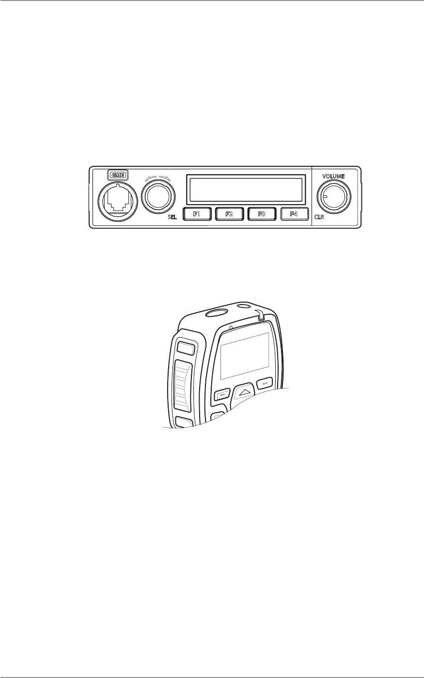
Radio Controls
Radio control funcons can be assigned only to programmable keys/buons on the local and remote
control head, and the microphone. Each key can be programmed with a dierent funcon and
acvated by a single press or hold. A press is less than one second and a hold is more than one and a
half seconds.
Local and Remote Setup
In the local and remote setups, all control funcons can be accessed on the control head and/or
the st microphone. Refer the Programmable Keys Control Funcons secon of this manual for
informaon on the control funcons programmed in the radio by the dealer. The gures in this
secon show parts of the local and remote control head and st microphone, and the funcons
assigned to the buons.
A buon
SEL (select)
Rotate for selecon
B buon
CLR (clear)
Volume control
On/Off
F1
Programmable
F2
Programmable
F3
Programmable
F4
Programmable
Figure 1 - Local Control Head / Remote Control Head
CM60 Series User Manual
09 May 2018
© 2018 Standard Communica ons Pty Ltd. All rights reserved.
13
49809-4
Content
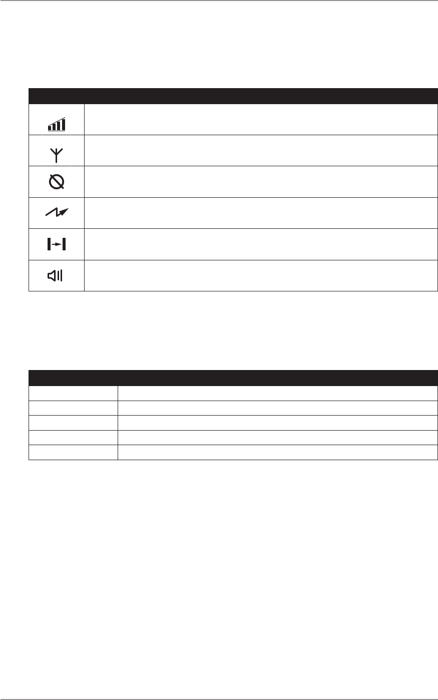
Call
Programmable key
Microphone
Down key
Programmable key
Up key
PTT buon
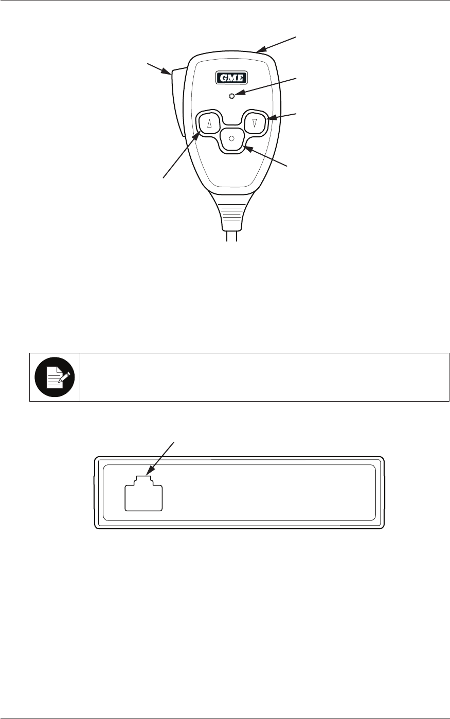
Figure 2 - Fist Microphone
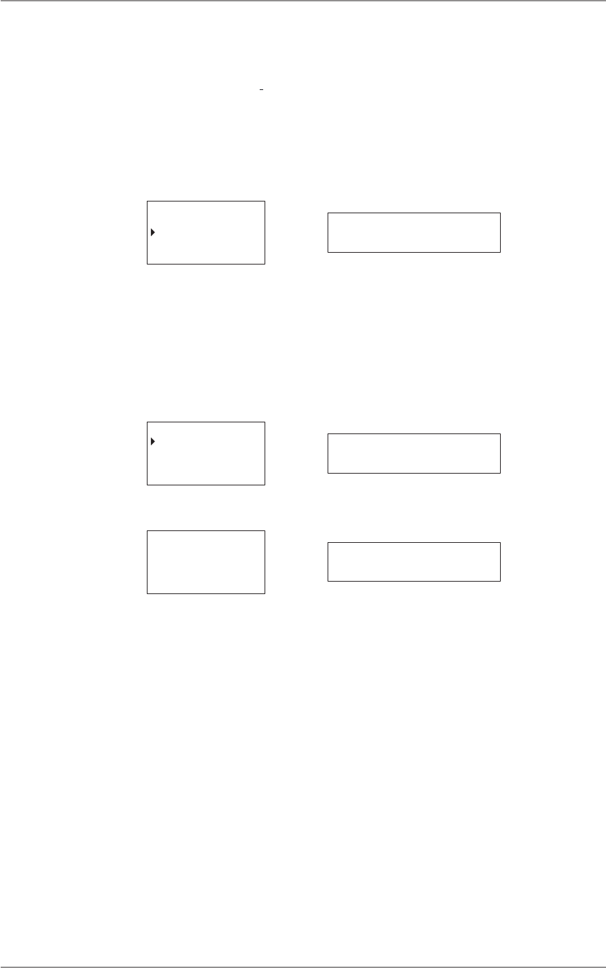
Extended Setup
All control func ons of the radio are assigned to keys/bu ons on the controller microphone when
the radio is ed with a remote control panel.
The socket on the remote control panel is only used with the controller microphone or the
remote control head.
Socket
Figure 3 - Remote Control Panel
CM60 Series User Manual
09 May 2018
© 2018 Standard Communicaons Pty Ltd. All rights reserved.
14
49809-4
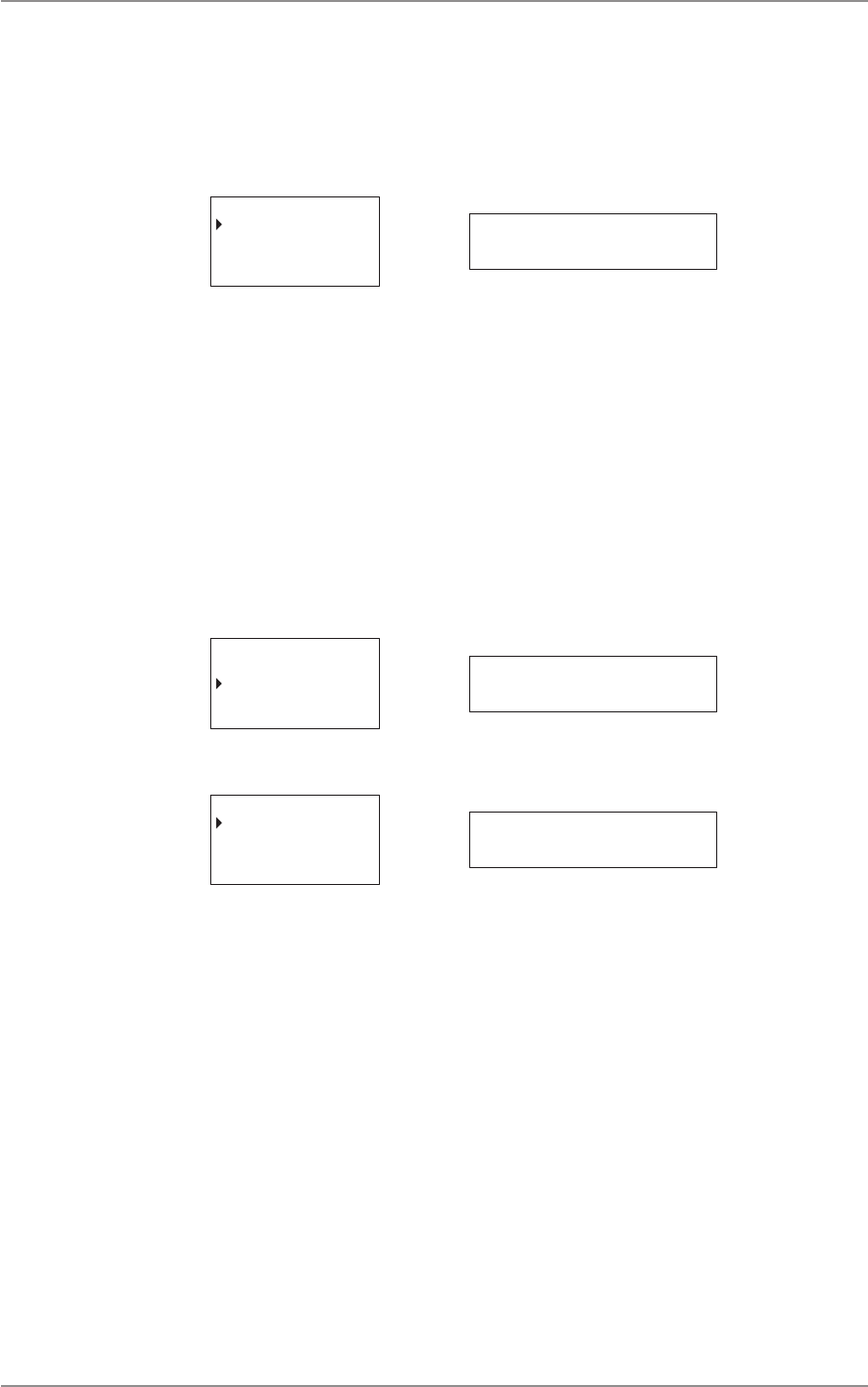
Content
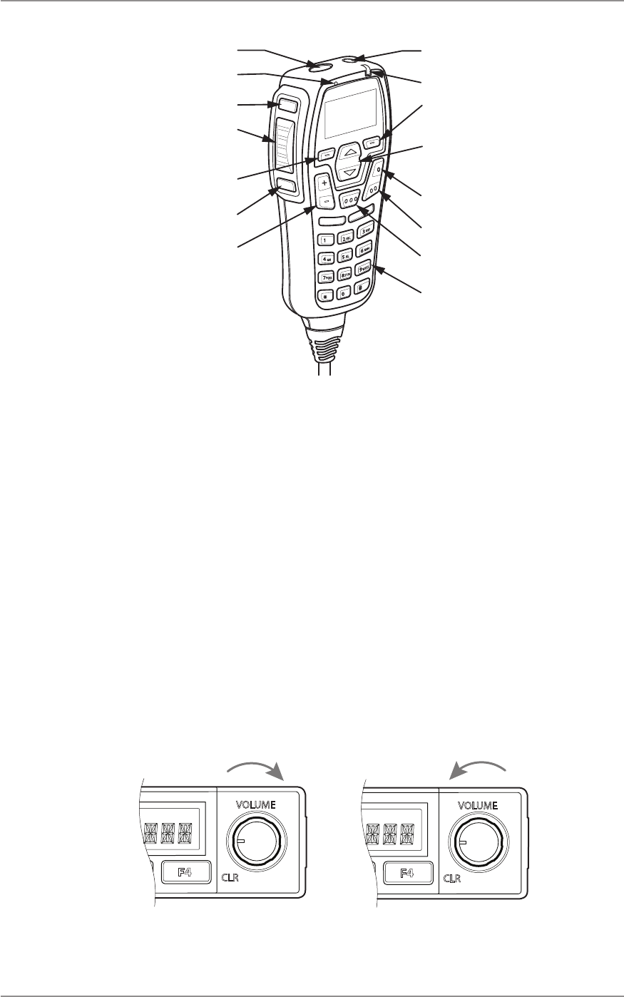
F4 Programmable
PTT (push to talk)
F5 Programmable
Volume up/down
Emergency buon
Microphone
Power buon
Status LED
Up/down
scroll keys
F1 Programmable
F2 Programmable
F3 Programmable
Backlit keypad
Alphanumeric keys
A buon
SEL (select)
B buon
CLR (clear)
Figure 4 - Controller Microphone
Programmable Keys
The dealer can assign control funcons to programmable keys on the radio. Contact the dealer or
refer the Programmable Keys Control Funcons secon of this manual for more informaon.
Hook On/O Funcon
The microphones used with the CM60 series radio are ed with interacve rear bollards that can
be programmed with an on/o hook funcon by a GME authorised professional dealership.
Turning the radio on and o
To turn the radio on using the control head, turn the volume knob (B buon) clockwise unl it clicks.
To turn radio o, turn volume knob an-clockwise unl it clicks.
On Off
Figure 5 - Turning the radio on and o
CM60 Series User Manual
09 May 2018
© 2018 Standard Communicaons Pty Ltd. All rights reserved.
15
49809-4
Content
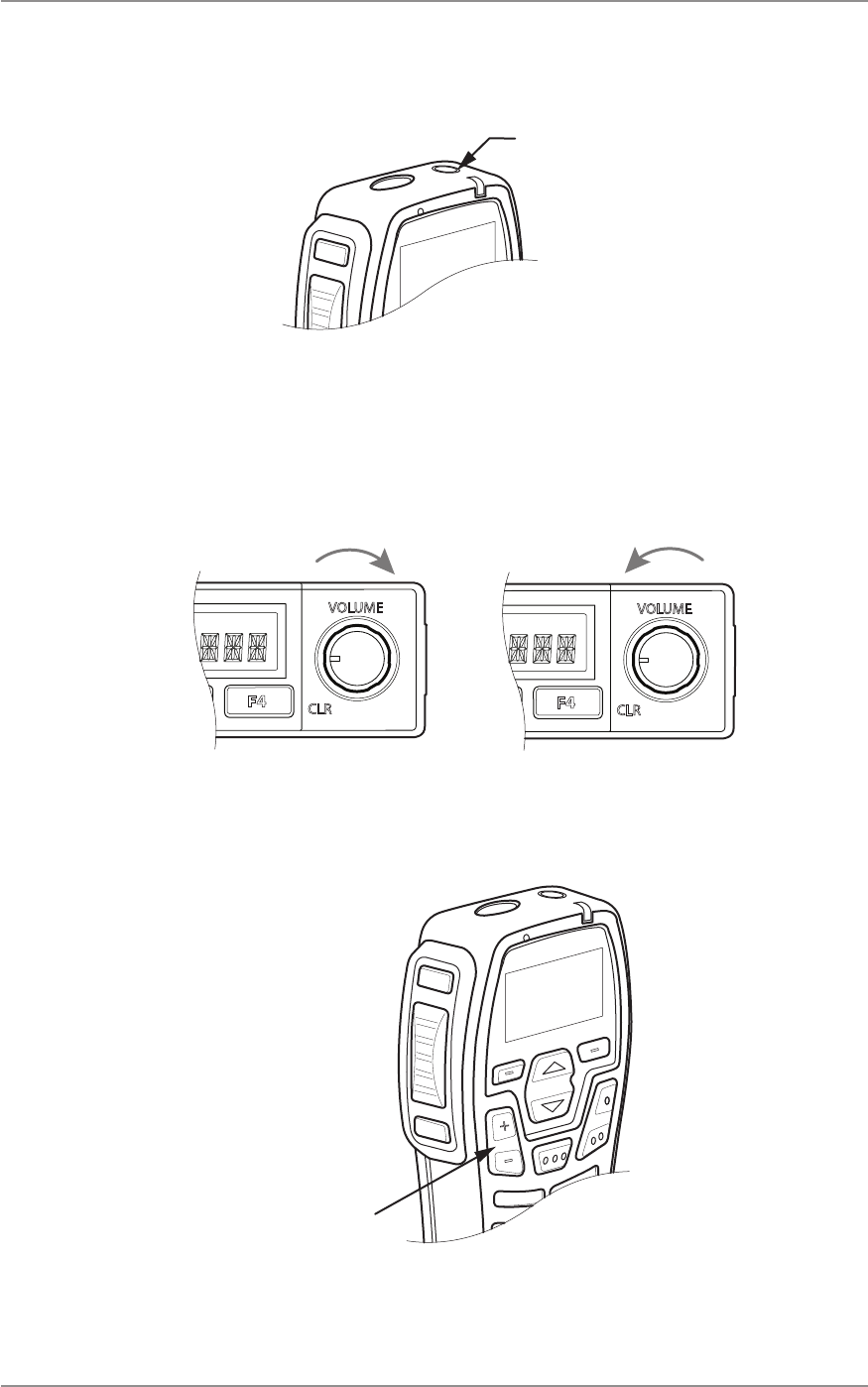
To turn radio on/o using the controller microphone, press and hold the power buon located on
top of the microphone.
Power buon
Figure 6 - Turning the radio on and o on controller microphone
Adjusng the Speaker Volume
To adjust the volume on local/remote control head, turn volume knob (B buon) clockwise to turn
the volume up. Turn volume knob an-clockwise to turn the volume down.
Figure 7 - Turning radio volume up and down
Use the up and down volume buons on the controller microphone.
Volume
up/down
Figure 8 - Turning radio volume up and down on controller microphone
CM60 Series User Manual
09 May 2018
© 2018 Standard Communicaons Pty Ltd. All rights reserved.
16
49809-4
Content
Displays
The radio and the controller microphone displays the current menu and the status of the radio.
When a menu is not accessed, the radio displays informaon such as the network and site the radio
is connected to.
Screen displays
The gure below shows the screen display on the local/remote control head control.
P25 CONV CH
Figure 9 - Local/Remote control head screen display
The gure below shows the screen display on the controller microphone.
P25 CONV CH
Menu
Figure 10 - Controller microphone screen display
CM60 Series User Manual
09 May 2018
© 2018 Standard Communicaons Pty Ltd. All rights reserved.
17
49809-4
Content
Display symbols
Display symbols indicate the state and condion of the radio. The table below describes display
symbols of the radio and controller microphone.
Symbol Meaning
Signal strength indicator. The more bars, the stronger the signal being received. This symbol
appears on the controller microphone only.
Trunking system available. The radio is operang on a P25 trunking system. Flashes indicates
that the radio is trying to register on a network.
Call is encrypted.
The radio is transming.
The radio is operang in repeater talkaround mode not using
a repeater.
A call is being received.
LEDs
The controller microphone is ed with an LED light that displays dierent colours depending the
radio status. The table below explains the meaning of the LED light colours.
Colour State/Acon
Red The radio is transming.
Green The radio is receiving a call.
Flashing green An incoming unit or phone call is ringing.
Orange Emergency mode is acve and the radio is not transming or receiving calls.
Slow ashing purple Radio is in programming mode.

CM60 Series User Manual
09 May 2018
© 2018 Standard Communicaons Pty Ltd. All rights reserved.
18
49809-4
Content
Tones
The radio uses audible tones to alert to its status. If tones are turned o no tones are audible. For
informaon on how to set the volume of tones refer to the Navigang the Radio Menus secon in
this manual.
The table below describes the tones and corresponding status of the radio.
Status Tone Level
P25 trunk/convenonal grant tone 2 successive high tones High
Outgoing/incoming P25 trunk unit call Phone ‘ring’ Obvious
P25 Service Up 3 rising tones High
P25 Service Down 3 falling tones Obvious
Generic ‘successful’ tone 2 successive high tones
Generic ‘failure’ tone Failure tone (mid > low) Obvious
Programmable key unavailable Failure tone (mid > low) Obvious
Key press, selecon, or eding complete
(can be disabled)
2 successive high tones High
Enter site mode 2 successive high tones User selectable, easily learned
Enter monitor mode 2 successive mid tones User selectable, easily learned
Enter emergency mode 3 successive high tones High
Incoming emergency call 3 successive high tones -
repeang
Obvious
Exit emergency mode Failure tone (mid > low) Obvious
Clear incoming emergency call Failure tone (mid > low) Obvious
Busy lockout call denied Failure tone (mid > low) Obvious
Enter PSTN call, Unit call, or Selecve
call
3 successive mid tones User selectable, easily learned
Exit PSTN call, Unit call, or Selecve call Failure tone (mid > low) User selectable, easily learned
Message, status or call alert received 1 high 1 low tone repeang User selectable, easily learned
Message, status, or call alert sent 2 successive high tones User selectable, easily learned
Message, status, or call send failed Failure tone (mid > low) User selectable, easily learned
Transmit meout warning (repeats each
second )
2 successive mid-tones 10
seconds prior me-out
Learned rst me
Transmit med out Failure tone (mid > low) Learned rst me
The CM60 series radio operates in the following three modes:
• Analog
• P25 convenonal
• P25 trunked

CM60 Series User Manual
09 May 2018
© 2018 Standard Communicaons Pty Ltd. All rights reserved.
19
49809-4
Content
Navigang the Radio Menus
Startup display
The local/remote head or the controller microphone screen display the last channel used or a
selected channel within the zone. Press the A buon to access the main menu.
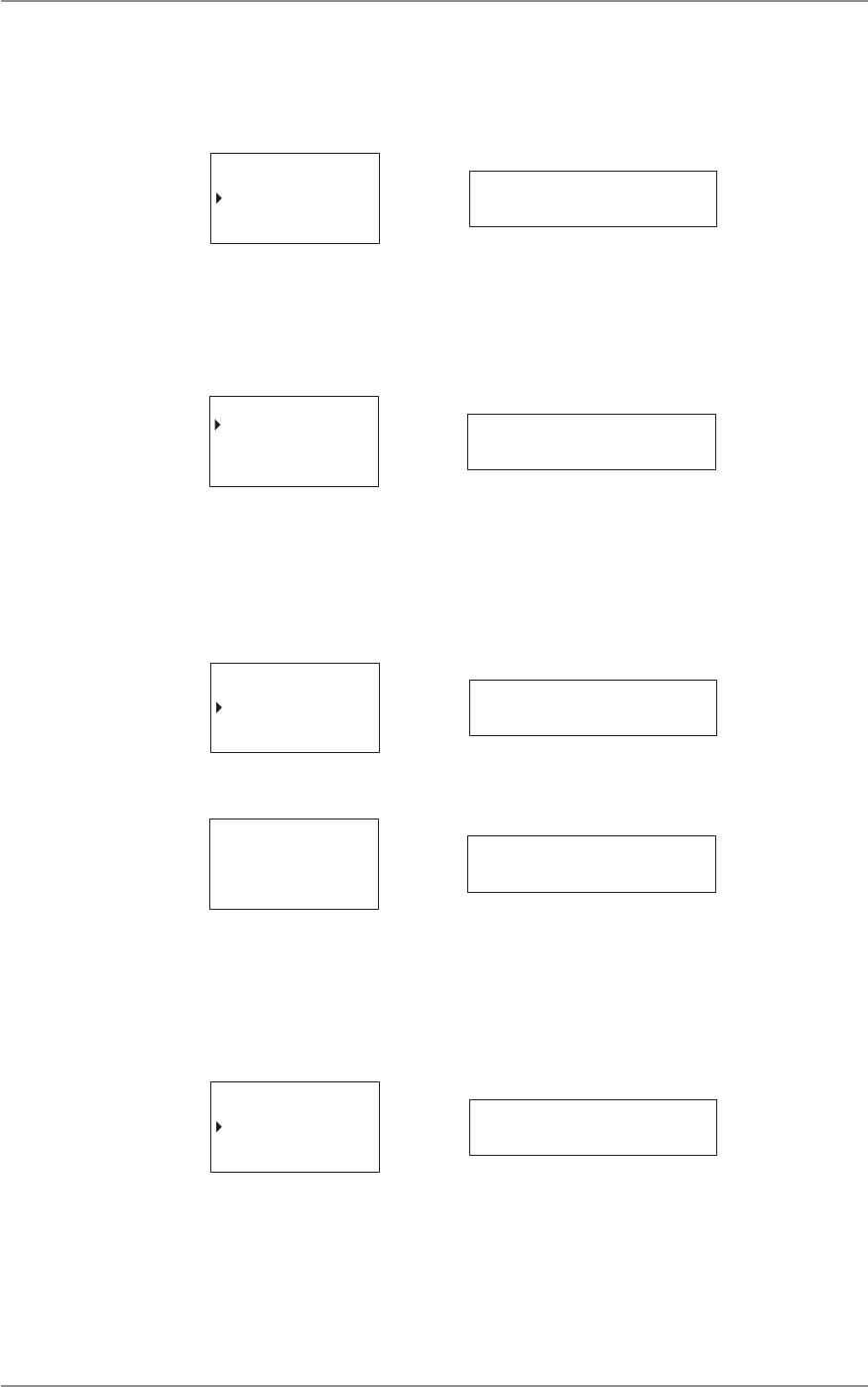
Channels
A channel contains frequencies the radio uses to transmit and receive signals. The Channels menu
displays a list of channels that are available in the currently selected zone.
To access the Channels menu:
1. Select Channels from the main menu.
2. Press the A buon to select Channels or the B buon to go back to the previous menu.
CHANNELS
ZONES
RECENT CALL
Select Back CHANNELS
Press the A buon to select or the B buon to go back to the previous menu.
To scroll through the Channels list:
• Use the up/down arrows on the controller microphone.
• Turn the selector knob on the local head.
Press the A buon to select a parcular channel and return to the main menu. Press the B buon to
go back to the previous menu.
P25 CONV CH
P25 TRNK CH
174-0
Select Back 174-0
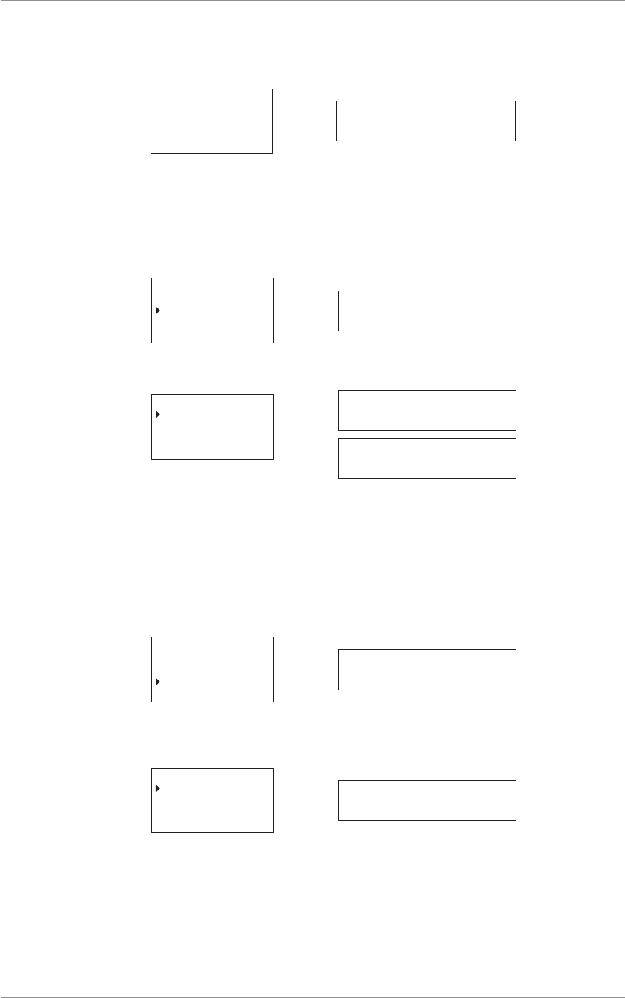
Zones
The radio can be programmed with up to 50 zones. A zone can contain a group of channels.
To access the Zones menu:
1. Scroll to Zones from the main menu.
2. Press the A buon to select Zones. Press the B buon to go back to the previous menu.
CHANNELS
ZONES
RECENT CALL
Select Back Zones

CM60 Series User Manual
09 May 2018
© 2018 Standard Communicaons Pty Ltd. All rights reserved.
20
49809-4
Content
To scroll through the zone list:
• Use the up/down arrows on the controller microphone.
• Turn the selector knob (A buon) on the local head.
Press the A buon to select a parcular zone and return to the main menu. Press the B buon to go
back to the previous menu.
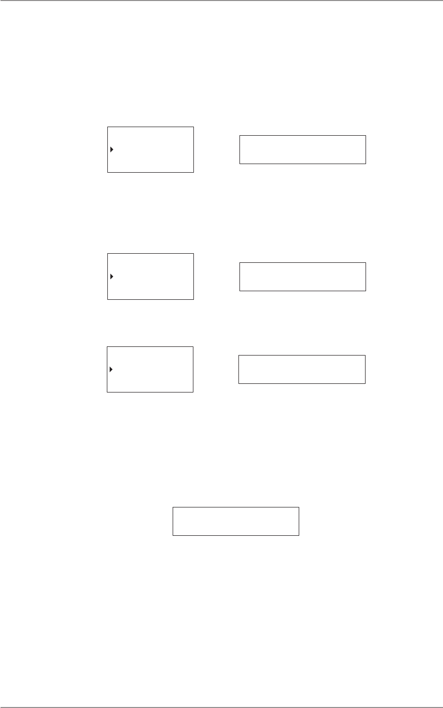
Recent Calls
This feature lists the 20 most recent calls made, received or missed by displaying the corresponding
Call ID or Unit ID. The most recent call is displayed rst on the list. Select a Call/Unit ID on this list to
call back. To access the Recent Calls menu:
1. Scroll to Recent Calls on the main menu.
2. Press the A buon to select Recent Calls. Press the B buon to go back to the previous
menu.
ZONES
RECENT CALL
RECENT MSG
Select Back recent call
To scroll through the recent call list:
• Use the up/down arrows on the controller microphone.
• Turn the selector knob (A buon) on the local head.
Press and hold the A buon to call back. Press the B buon to go to the previous menu.
Recent Messages
This feature shows the ten most recent messages that were sent or received. The most recent
message is displayed rst on the list.
To access the Recent Messages menu:
1. Select Recent Messages from the main menu.
2. Press the A buon to select Recent Messages. Press the B buon to go back to the
previous menu.
RECENT CALL
RECENT MSG
SELCALL
Select Back recent msg
To scroll through the Recent Messages list:
• Use the up/down arrows on the controller microphone.
• Turn the selector knob (A buon) on the local head.
Press the B buon to go back to the previous menu.
CM60 Series User Manual
09 May 2018
© 2018 Standard Communicaons Pty Ltd. All rights reserved.
21
49809-4
Content
Unit Call
The Unit Calls menu displays a list of all P25 trunked/convenonal units in the contact book.
To access the Unit Call menu:
1. Select Unit Call from the main menu.
2. Press the A buon to select Unit Call. Press the B buon to go back to the previous
menu.
RECENT MSG
UNIT CALL
SELCALL
Select Back unit call
To scroll through the list of contacts:
• Use the up/down arrows on the controller microphone.
• Turn the selector knob on the local head.
The rst item in the list is Enter ID. The radio enters numeric edit mode and a custom unit ID can be
entered and used to acvate a call if selected.
Enter ID
Select Back enter id
Press the A buon to accept and the B buon to delete.
Enter ID
-
Accept Delete enter id
Press the B buon to exit this menu without making a call.
P25 Trunked Channels
To make a Unit Call to a predened ID on the controller microphone:
1. Select Unit Call from the main menu. The rst item on the list is Enter ID followed by any
predened IDs.
2. Press and hold the A buon to select and call a predened ID. Press the B buon to exit
the call.
3. To make a Unit Call to a predened ID on the local/remote control head:
4. Select Unit Call from the main menu.
5. The rst item in the menu is Enter ID. Turn the selector knob to display any predened
IDs in the menu.
6. Press and hold the selector knob to select and iniate a call to a predened ID.

CM60 Series User Manual
09 May 2018
© 2018 Standard Communicaons Pty Ltd. All rights reserved.
22
49809-4
Content
P25 Convenonal Channels
To make a Unit Call to a predened ID on the controller microphone:
1. Select Unit Call from the main menu. The rst item on the list is Enter ID followed by any
predened IDs.
2. Press and hold the A buon to select and iniate a call to a predened ID. The display will
show In Call and Unit ID When a unit call is iniated.
3. Press the PTT to send the unit call.
4. To make a Unit Call to a predened ID on the local/remote control head:
5. Select Unit Call from the main menu. The rst item in the menu is Enter ID. Turn the
selector knob to display any predened IDs in the menu.
6. Press and hold the selector knob to select and call a predened ID. The display will toggle
between Unit ID and In Call when a unit call is iniated.
7. Press the PTT within ten seconds to send the unit call. The radio will return to channel if
the unit call is not sent.
P25 Trunked Channels
To enter a custom ID and iniate a unit call on the controller microphone:
1. Select Unit Call from the main menu.
2. Press the A buon to select Enter ID.
3. Enter the ID using the alphanumeric keypad.
4. Press the A buon to iniate the unit call.
To enter a custom ID and iniate a unit call on the local/remote control head:
1. Select Unit Call from the main menu.
2. Press the selector knob to select Enter ID.
3. Turn the knob to select a digit. Press the knob to enter the next digit.
4. Press and hold the knob to iniate the unit call when the enre number is entered.
P25 Convenonal Channels
To enter a custom ID and iniate a unit call on the controller microphone:
1. From the main menu, select Unit Call.
2. Press the A buon to select Enter Num.
3. Enter the ID using the alphanumeric keypad.
4. Press and hold the A buon to iniate the unit call. The display will show In Call and Unit
ID when a unit call is iniated.
5. Press the PTT to send the unit call.

CM60 Series User Manual
09 May 2018
© 2018 Standard Communicaons Pty Ltd. All rights reserved.
23
49809-4
Content
To enter a custom ID and iniate a unit call on the local/remote control head:
1. Select Unit Call from the main menu.
2. Press the selector knob to select Enter ID.
3. Turn the knob to select a digit. Press the knob to enter the next digit.
4. Press and hold the knob to iniate the unit call When the enre number is entered. The
display will toggle between Unit ID and In Call when a unit call is iniated.
5. Press the PTT within 10 seconds to send the unit call. The radio will return to channel if
the unit call is not sent.
Selcall (Selecve Calling)
Selecve Calling is an analog signaling technology which operates like a telephone where a call to a
specic radio uses the custom unique ID of the radio.
To access the Selcall menu:
1. Scroll to Selcall on the main menu.
2. Press the A buon (selector knob) to select Selcall, or the B buon to go back to the
previous menu.
RECENT MSG
SELCALL
SEND DMTF
Select Back selcall
To scroll through the Selcall list:
• Use the up/down arrows on the controller microphone.
• Turn the selector knob on the local head.
The SelCall menu displays a list of all SelCall contacts in the contact book. The rst item in the list is
Enter ID.
To enter a custom ID and to iniate a Selcall on the controller microphone:
1. Press the A buon to select Enter ID.
2. Enter the ID using the alphanumeric keypad.
3. Press and hold the A buon to iniate the Selcall.
To enter a custom ID and to iniate a Selcall on the local/remote control head:
1. Press the selector knob to select Enter ID.
2. Press the selector knob to select the next ID digit.
3. Press and hold the selector knob to iniate a unit call.
Enter ID
Select Back enter Id

CM60 Series User Manual
09 May 2018
© 2018 Standard Communicaons Pty Ltd. All rights reserved.
24
49809-4
Content
To select a predened Selcall:
1. Press the up/down buons on the UIC or rotate the selector knob on the local head.
2. Press the A buon to accept and send the call. Press the B buon to go back.
Enter ID
-
Accept Delete enter id
The radio can be put in quiet mode. Incoming transmissions are muted unl the radio receives a
matching selecve call (SelCall) when the radio is in quiet mode.
Phone Call
This feature allows a radio on a trunking system to make a phone call. The phone call menu displays
a list of all P25 PSTN contacts on P25 trunked channels in the contact book.
To access the Phone Call menu:
1. From the main menu, select Phone Call.
2. Press the A buon to select or the B buon to go back to the previous menu.
SELCALL
PHONE CALL
SERVICES
Select Back phone call
To scroll through Phone Call list:
• Use the up/down arrows on the controller microphone.
• Turn the selector knob (A buon) on the local head.
The rst item in the list is Enter Num. If selected, the radio enters numeric edit mode and a custom
phone number can be entered.
Enter Num
-
Accept Delete enter num
Press the A buon to select and the B buon to exit this menu.
To iniate a phone call on the controller microphone:
1. Press the A buon to select Enter Num.
2. Use the numeric keypad to enter a phone number.
3. Press and hold the A buon to iniate the phone call and return to the main screen.
CM60 Series User Manual
09 May 2018
© 2018 Standard Communicaons Pty Ltd. All rights reserved.
25
49809-4
Content
To iniate a phone call on the local/remote control head:
1. If Enter Num is selected, turn the selector knob to select a digit.
2. Press the knob to enter the next digit.
3. Press and hold the knob to iniate the phone call when the enre number is entered.
Enter Num
Select Back -----------
Press the B buon to exit the list without making a call.
Send DTMF
DTMF (Dual Tone Mulple Frequency) is an analog signaling system used to connect to a telephone
network by a telephone interconnect device. The Send DTMF opon sends a predened string of
DTMF tones for keying up a repeater.
To access the Send DTMF menu:
1. Select Send DTMF from the main menu.
2. Press the A buon to select or the B buon to go back to the previous menu.
SELCALL
SEND DTMF
SETTINGS
Select Back send dtmf
The rst item in the list is Enter STRIN.
Enter String
Select Back enter strin
To iniate a call using a custom DTMF string on the controller microphone:
1. Press the A buon to select Enter Num.
2. Use the numeric keypad to enter a phone number.
3. Press and hold the A buon (Accept) to iniate a DTMF call and return to the main
screen.
To iniate a call using a custom DTMF string on the local/remote control head:
1. Turn the selector knob to select a digit if Enter Num is selected.
2. Press the knob to enter the next digit.
3. When the enre number is entered, press and hold the knob to iniate the call.

CM60 Series User Manual
09 May 2018
© 2018 Standard Communicaons Pty Ltd. All rights reserved.
26
49809-4
Content
To iniate a call using a predened DTMF string on the controller microphone:
1. Select the DTMF menu. The rst item in the list is Enter String.
2. Press the down key to select string. Press the A buon to iniate call.
To iniate a call using a predened DTMF string on the local/remote control head:
1. Select the DTMF menu. The rst item in the list is Enter String.
2. Turn the selector knob to select a string.
3. Press the knob to iniate call.
Enter String
-
Accept Delete enter strin
Services
The Services menu is available for the P25 trunked and P25 convenonal channels. For analog
channels the Services menu becomes available only if Digital Selcall is enabled. Digital Selcall
(MDC1200) is a digital signalling technology that is used for analog channels. The CM60 series
programming manual contains informaon on conguring the radio to use digital selcall. Services
provide features that are listed and described in the table below.
Feature Detail Descripon
SEND MSG Send message Provides list of predened short messages that can be sent to another
radio.
SEND ALERT Send alert Sends page alert call to another radio user alerng them that you want
to talk to them.
SEND STATUS Send status Custom or predened status messages used to inform another radio of
your current status.
SET STATUS Set status Allows you to select and set a status message indicang your current
status.
STATUS REQ Status request Allows you to send a signal to another radio requesng a status update.
CHECK REQ Check request Sends a radio check message to conrm whether a radio is available on
the system or is within communicaon range.
INHIBIT REQ Inhibit request Sends a request to prevent a radio from transming. The Inhibit Request
feature is similar to Stun in the exisng MDC system.
UNINHIBIT
REQ
Uninhibit request Sends a request to stop prevenng a radio from transming. The
Uninhibit Request feature is similar to Revive in the exisng MDC system.

CM60 Series User Manual
09 May 2018
© 2018 Standard Communicaons Pty Ltd. All rights reserved.
27
49809-4
Content
To access the Services menu:
1. Select Services from the main menu.
2. Press the A buon to select or the B buon to go back to the previous menu.
PHONE CALL
SERVICES
TRUNKING
Select Back services
The following secons explain each of the Services features in detail.
Send MSG
The Send MSG (Send Message) feature provides a list of predened short messages that can be sent
to another radio. The radio displays Send MSG aer the receiving radio has received the message.
To access the Send MSG menu:
1. Select Services from the main menu.
2. Select send MSG.
3. Press the A buon to select or the B buon to go back.
SEND MSG
SEND ALERT
SEND STATUS
Select Back send msg
The rst screen displays the rst message of the message list on local/remote control head. To send
a message:
1. Press the knob to enter ID.
2. Press the selector knob to enter the radio ID.
3. Press the selector knob to select the next digit.
4. Press and hold the selector knob to send the message.
The rst screen displays a list of messages on the controller microphone. To send a message:
1. Press the up/down keys to select a message, and press the A buon to select the
message.
2. Press the A buon to enter ID.
3. Press and hold the A buon to send the message.
4. Press the A buon to select and the B buon to go back to the previous menu.
Press the A buon to accept and the B buon to delete.
Enter ID
-
Accept Delete enter id
The screen displays the message No Entries if no predened messages exist in the radio.

CM60 Series User Manual
09 May 2018
© 2018 Standard Communicaons Pty Ltd. All rights reserved.
28
49809-4
Content
Send Alert (Page)
The Send Alert feature allows for an alert to be send to another radio requesng communicaon.
To access the Send Alert menu:
1. Select Services from the main menu.
2. Select Send Alert.
3. Press the A buon to select or the B buon to go back.
SEND MSG
SEND ALERT
SEND STATUS
Select Back send alert
Enter ID
Select Back enter id
To send an alert to a custom radio ID on the controller microphone:
1. Press the A buon to select.
2. Enter the radio ID using the numeric keypad.
3. Press the A buon to iniate the page alert.
To send an alert to a custom radio ID on the local/remote control head:
1. Press the selector knob to select Enter ID.
2. Turn the knob to select a digit. Press the knob to enter the next digit.
3. Enter the enre number. Press and hold the knob to send the page alert.
To send an alert to a predened radio ID on the controller microphone:
1. Press the up/down key to select a predened radio ID.
2. Press and hold the A buon to send the page alert.
To send an alert to a predened radio ID on the local/remote control head:
1. Turn the selector knob to select a predened radio ID.
2. Press and hold the knob to send the page alert.
The radio displays Page Sent aer the receiving radio has received the page alert.
Enter ID
-
Accept Delete enter id

CM60 Series User Manual
09 May 2018
© 2018 Standard Communicaons Pty Ltd. All rights reserved.
29
49809-4
Content
Send Status
The Send Status opon allows the radio to inform another radio of the user’s current status by
choosing a predened status message.
To access the Send Status menu:
1. Select Services from the main menu.
2. Select Send Status.
3. Press the A buon to select, or the B buon to go back.
SEND ALERT
SEND STATUS
SET STATUS
Select Back send status
The rst item displayed is Enter ID if Send Status is selected.
To send status message to a custom radio ID on the controller microphone:
1. Press the A buon.
2. Enter the radio ID using the numeric keypad.
3. Press the A buon to send the status message.
To send status message to a custom radio ID on the local/remote control head:
1. Press the selector knob to select Enter ID.
2. Turn the knob to select the rst digit for the ID. Next press the knob to enter the next
digit.
3. Press and hold the knob to send the status message when the enre ID is entered.
To send status message to a predened radio ID on the controller microphone:
1. Press the up/down key to select a predened radio ID.
2. Press the A buon to send the status message.
To send status message to a predened radio ID on the local/remote control head:
1. Turn the selector knob (A buon) to select a predened radio ID.
2. Press and hold the knob to send the status message.
The radio displays STS Sent aer the receiving radio has received your status message.

CM60 Series User Manual
09 May 2018
© 2018 Standard Communicaons Pty Ltd. All rights reserved.
30
49809-4
Content
Set Status
The Set Status opon allows selecon and seng a status message that indicates the radio’s current
status. The selected message remains set in the radio unl updated with another message. Any
radios sent a status request will know the current status. The Set Status opon also allows access to
a list of predened status messages in the radio.
To access the Set Status menu:
1. Select the Services from the main menu.
2. Select Set Status.
3. Press the A buon to select or the B buon to go back.
The Set Status opon is displayed only when the Status Message feature is enabled in the radio.
SEND STATUS
SET STATUS
SET REQ
Select Back set status
To set status on the controller microphone:
1. Press the up/down keys and select Set Status.
2. Select the status message and then press the A buon (Select).
To set status on the local/remote control head:
1. Turn the selector knob (A buon) to select Set Status.
2. Turn the knob to select the message.
3. Press and hold the knob to set the status message.
The radio will display Status Set when the message is set.
Status Request
The Status Request opon allows a signal to be sent to another radio asking for a status update. The
Status Request opon allows access to a list of predened requests in the radio.
To access the Set Request menu:
1. Select Services from the main menu.
2. Select status Request.
3. Press the A buon to select or the B buon to go back.
SEND STATUS
SET STATUS
STATUS REQ
Select Back sTATUS req

CM60 Series User Manual
09 May 2018
© 2018 Standard Communicaons Pty Ltd. All rights reserved.
31
49809-4
Content
4. The rst item displayed is Enter ID if Status Req is selected.
Enter ID
Select Back enter id
5. Press the A buon to select and the B buon to go back to the previous menu.
To send status request to a custom radio ID on the controller microphone:
1. Press the A buon.
2. Enter the radio ID using the numeric keypad.
3. Press the A buon to send the status request.
To send status request to a custom radio ID on the local/remote control head:
1. Press the selector knob to select Enter ID.
2. Turn the knob to select the rst digit for the ID. Next, press the knob to enter the next
digit.
3. Press and hold the knob to send the status request when the enre ID is entered.
To send status request to a predened radio ID on the controller microphone:
1. Press the up/down key to select a predened radio ID.
2. Press and hold the A buon to send the status request.
3. Press the A buon to accept and the B buon to delete.
To send status request to a predened radio ID on the local/remote control head:
1. Press the selector knob (A buon) to select Enter ID.
2. Turn the selector knob (A buon) to select a predened radio ID.
3. Press and hold the knob to send the status request.
Enter ID
-
Accept Delete enter id
Status Rcvd is displayed aer the recipient radio has received the status request. Press the A buon
to view status of the recipient radio and the B buon to exit.

CM60 Series User Manual
09 May 2018
© 2018 Standard Communicaons Pty Ltd. All rights reserved.
32
49809-4
Content
Check Request
The Check Request feature sends a radio check message to conrm whether a radio is available on
the system or in communicaon range.
To access the Check Request menu:
1. Select Services from the main menu.
2. Select Check Request.
3. Press the A buon to select or the B buon to go back. The rst item displayed is Enter ID
if Check Request is selected.
4. Press the A buon to select and the B buon to go back to the previous menu.
To send Check Request to a custom radio ID on the controller microphone:
1. Press and hold the A buon.
2. Enter the radio ID using the numeric keypad.
3. Press the A buon to send the check request.
To send Check Request to a custom radio ID on the local/remote control head:
1. Press the selector knob to select Enter ID.
2. Turn the knob to select the rst digit for the ID. Next, press the knob to enter the next
digit.
3. When the enre ID is entered, press and hold the knob to send the check request.
To send Check Request to a predened radio ID on the controller microphone:
1. Press the up/down key to select a predened radio ID.
2. Press the A buon to send the check request.
To send Check Request to a predened radio ID on the local/remote control head:
1. Turn the selector knob to select a predened radio ID.
2. Press and hold the knob to send the check request.
Enter ID
-
Accept Delete enter id
The message Success is displayed if the radio is available on the system. Press the A buon to accept
and the B buon to delete.
sUCCESS

CM60 Series User Manual
09 May 2018
© 2018 Standard Communicaons Pty Ltd. All rights reserved.
33
49809-4
Content
Inhibit Request
A radio that is congured with this feature can send an Inhibit Request that prevents a selected radio
from operang. The Inhibit Request feature is similar to Stun in the exisng MDC system.
To access the Inhibit Request menu:
1. Select Services from the main menu.
2. Select Inhibit Request.
3. Press the A buon to select or the B buon to go back. The rst item displayed is Enter ID
if Inhibit Request is selected.
To send inhibit request to a custom radio ID on the controller microphone:
1. Press the A buon.
2. Enter the radio ID using the numeric keypad.
3. Press and hold the A buon to send the inhibit request.
To send inhibit request to a custom radio ID on the local/remote control head:
1. Press the selector knob (A buon) to select Enter ID.
2. Turn the knob to select the rst digit for the ID. Next, press the knob to enter the next
digit.
3. When the enre ID is entered, press and hold the knob to send the inhibit request.
To send inhibit request to a predened radio ID on the controller microphone:
1. Press the up/down key to select a predened radio ID.
2. Press the A buon to send the inhibit request.
To send inhibit request to a predened radio ID on the local/remote control head:
1. Turn the selector knob to select a predened radio ID.
2. Press and hold the knob to send the inhibit request.
Enter ID
-
Accept Delete enter id
Inhibit Sent displays aer an Inhibit Req message is sent. A radio that is inhibited displays the
message Inhibited on the screen.

CM60 Series User Manual
09 May 2018
© 2018 Standard Communicaons Pty Ltd. All rights reserved.
34
49809-4
Content
Uninhibit Request
A radio that is congured for this feature can send an Uninhibit Request to an inhibited radio
allowing it to resume operaon. The Uninhibit Request feature is similar to Revive in the MDC
system.
To access the Uninhibit Request menu:
1. Select Services from the main menu.
2. Select Uninhibit Request.
3. Press the A buon to select or the B buon to go back. The rst item displayed is Enter ID
if Uninhibit Request is selected.
4. Press the A buon to select and the B buon to go back to the previous menu.
To send uninhibit request to a custom radio ID on the controller microphone:
1. Press the A buon.
2. Enter the radio ID using the numeric keypad.
3. Press and hold the A buon to send the uninhibit request.
To send uninhibit request to a custom radio ID on the local/remote control head:
1. Press the selector knob to select Enter ID.
2. Turn the knob to select the rst digit for the ID. Press the knob to enter the next digit.
3. When the enre ID is entered, press and hold the knob to send the uninhibit request.
To send an Uninhibit Request to a predened radio ID on the controller microphone:
1. Press the up/down key to select a predened radio ID.
2. Press the A buon to send the uninhibit request.
To send an Uninhibit Request to a predened radio ID on the On local/remote control head:
1. Turn the selector knob to select a predened radio ID.
2. Press the knob to send the uninhibit request.
Enter ID
-
Accept Delete enter id
Uninhibit sent is displayed aer an Uninhibit request message is sent.

CM60 Series User Manual
09 May 2018
© 2018 Standard Communicaons Pty Ltd. All rights reserved.
35
49809-4
Content
Trunking
The Trunking menu allows access to a range of opons that are available only when the radio is set
to a trunking channel.
To access the Trunking menu:
1. Ensure that a trunking channel is chosen.
2. Select Trunking from the main menu.
3. Press the A buon to select or the B buon to go back to the previous menu.
SETTINGS
SERVICES
TRUNKING
Select Back trunking
The trunking menu displays the following opons:
• Force Hunt
• Network Info
• Radio ID
• Site Name
• Site Lock
• Site Select
Force Hunt
The Force Hunt feature is used to search and nd a control channel by forcing the radio to re-scan a
short or extended list of control channels.
FORCE HUNT
NETWORK INFO
RADIO ID
Select Back force hunt
Press the A buon to select and the B buon to go back to the previous menu. The following two
opons are available under Force Hunt:
• Short Hunt:
Forces the radio to search through its list of received adjacent site channels, ranking from
the highest to lowest channels.
• Extended Hunt:
Forces the radio to search through its list of all known control channels programmed into
the radio if no valid control channel is located by the short hunt method.
SHORT
EXTENDED
Select Back short
Press the A buon to select and the B buon to go back to the previous menu.
CM60 Series User Manual
09 May 2018
© 2018 Standard Communicaons Pty Ltd. All rights reserved.
36
49809-4
Content
Network Info
The Network Info feature displays a list of informaon relang to the current trunking network.
FORCE HUNT
NETWORK INFO
RADIO ID
Select Back network inf
Press the A buon to select and the B buon to go back to the previous menu. To scroll through the
Network Info list:
• Use the up/down arrows on the controller microphone.
• Turn the selector knob (A buon) on the local head.
WACN ID 3
SYS ID 2
RFSS ID 1
Exit WACN ID 3
Press the B buon to exit.
Radio ID
The Radio ID opon displays the radio’s ID number.
NETWORK INFO
RADIO ID
SITE NAME
Select Back radio id
Press the A buon to select and the B buon to go back to the previous menu.
T1200
Exit T1200
Press the B buon to exit.
Site Name
The Site Name opon displays the name of the site the radio is on and connected to.
RADIO ID
SITE NAME
SITE LOCK
Select Back site name
CM60 Series User Manual
09 May 2018
© 2018 Standard Communicaons Pty Ltd. All rights reserved.
37
49809-4
Content
Press the A buon to select and the B buon to go back to the
previous menu.
SITE ID: 2
Exit site id 2
Press the B buon to go back to the previous menu.
Site Lock
The Site Lock opon allows for the radio to be locked to a specic site.
SITE NAME
SITE LOCK
SITE SELECT
Select Back site lock
Press the A buon to select and the B buon to go back to the previous menu.
LOCK
UNLOCK
Select Back
lock
UNlock
Press the A buon to select and the B buon to go back to the
previous menu.
Site Select
The Site Select opon allows you to select a specic site on the radio.
SITE NAME
SITE LOCK
SITE SELECT
Select Back site select
Press the A buon to select and the B buon to go back to the previous menu. The rst item
displayed is Enter ID if Site Select is selected.
Enter ID
Select Back enter id
Press the A buon to select and the B buon to go back to the previous menu. To select a specic
site using site ID on the controller microphone:
1. Press the A buon.
2. Enter the site ID using the numeric keypad.
3. Press the A buon to select the site.

CM60 Series User Manual
09 May 2018
© 2018 Standard Communicaons Pty Ltd. All rights reserved.
38
49809-4
Content
To select a specic site using site ID on the local/remote control head:
1. Press the selector knob to select ‘Enter ID’.
2. Turn the knob to select the rst digit for the ID. Press the knob to enter the next digit.
3. Press and hold the knob to select the site when the enre ID is entered.
Enter ID
-
Accept Delete enter id
Sengs
The Sengs opon contains a list of opons that can be set for the radio.
To access the Sengs menu:
1. Select Sengs from the main menu.
2. Press the A buon to select or the B buon to go back to the previous menu.
SELCALL
SEND DMTF
SETTINGS
Select Back settings
The Sengs menu displays the following opons:
• Alert Level
• Channel Info
• Display
• Funcons
• Radio Info
• Speakers
• Bluetooth
Alert Level
The Alert Level seng allows you to set the audio output level of a beep.
ALERT LEVEL
CHAN INFO
FUNCTIONS
Select Back alert level
Press the A buon to select and the B buon to go back to the previous menu. The seng has two
opons, beep level and key tones.

CM60 Series User Manual
09 May 2018
© 2018 Standard Communicaons Pty Ltd. All rights reserved.
39
49809-4
Content
Beep Level
The Beep Level opon allows you to set the level of the beep tone.
BEEP 5
Accept Back beep 5
To access the Beep Level:
1. Select Sengs from the main menu
2. Select Alert Level.
3. Select Beep Level.
To set the beep tone level:
1. Turn the selector knob on the local head to scroll through dierent levels. Use the up/
down arrows on the controller microphone.
2. Set the beep tone level by choosing a tone level between BEEP 0 and BEEP 9.
3. Press the A buon to select and to return to the Alert Level menu. Press the B buon to
return the beep level to its inial level and return to the Alert Level menu.
BEEP 5
Accept Back beep 5
Key Tones
The Key Tones feature allows you to set the alert key tones.
BEEP LEVEL
KEY TONES
Select Back key tones
To access Key Tones:
1. Select Seng from the main menu.
2. Select Alert Level.
3. Select Key Tones.
CM60 Series User Manual
09 May 2018
© 2018 Standard Communicaons Pty Ltd. All rights reserved.
40
49809-4
Content
To set/change the alert key tone:
1. Turn the selector knob on the local head. Use the up/down arrows on the controller
microphone to scroll through the on/o opons.
2. Press the A buon to turn the key tones o or on by choosing either opon and return to
the Alert Level menu.
3. Press the B buon to leave the key tone unchanged and return to the Alert Level menu.
OFF
ON
Select Back ON
Channel Info
The Channel Info displays the conguraon informaon for the set channel. Press the A buon to
access the menu.
ALERT LEVEL
CHAN INFO
FUNCTIONS
Select Back chan info
Use the selector knob on the local head, or the up/down buons on the controller microphone to
scroll the informaon on the display.
174-0
ANALOG
TX 174.0000MHz
Exit analog
Press the B buon to go exit.
Display
The Display opon allows the backlight brightness for the radio display to be set. The opon is
available for the local and remote setup only. The controller microphone automacally adjusts the
backlight.
backlight
Press the A buon to access the Backlight menu.

CM60 Series User Manual
09 May 2018
© 2018 Standard Communicaons Pty Ltd. All rights reserved.
41
49809-4
Content
To set the backlight brightness:
1. Turn the selector knob on the local head to scroll through dierent levels.
2. Set the brightness level by choosing a level between BKLGT 1 and BKLGT 16.
3. Press the A buon to select and to return to the Display menu. Press the B buon to
leave inial brightness level unchanged, and return to the Backlight menu.
bklgt 16
Funcons
The Funcons menu allows access to funcons such as locking the radio, squelch level (for analog
channels only) and transmission power.
To access the Funcons menu:
1. Select Sengs from the main menu.
2. Select Funcons.
CHAN INFO
FUNCTIONS
RADIO INFO
Select Back functions
This seng has the following opons:
• Lock Radio
• Squelch Level
• TX Power
Lock Radio
The Lock Radio feature allows the radio to be locked.
LOCK RADIO
SQUELCH LVL
TX POWER
Select Back lock radio
To lock the radio on the controller microphone:
1. Select Sengs from the main menu.
2. Select Funcons.
3. Select Lock Radio. The screen displays the message LOCK?.
4. Press the A buon to lock the radio. The lock details are displayed on the screen.

CM60 Series User Manual
09 May 2018
© 2018 Standard Communicaons Pty Ltd. All rights reserved.
42
49809-4
Content
To lock the radio on the local/remote control head:
1. Select Sengs from the main menu.
2. Select Funcons.
3. Select Lock Radio. The screen displays the message LOCK.
4. Press the A buon to lock the radio. The lock details are displayed on the screen.
LOCK?
Accept Back lock
LOCKED
174-0
Unlock locked
To unlock the radio:
1. Press the A buon to access the Unlock opon.
2. Press the A buon again to unlock the radio. The radio may require a PIN to unlock if
congured for PIN entry. For informaon on how to change the PIN, refer the Change PIN
secon of this manual.
UNLOCK?
Accept Back unlock
Squelch Level (for Analog Channels Only)
Squelch is used to eliminate any annoying background noise when there are no signals present. The
Squelch Level opon allows the squelch level to be set. Squelch level 1 allows the squelch to open on
very weak signals, whereas squelch level 9 requires much stronger signals to overcome the squelch.
LOCK RADIO
SQUELCH LVL
TX POWER
Select Back squelch lvl
To access Squelch Level:
1. Select Sengs from the main menu.
2. Select Funcons.
3. Select Squelch Level.

CM60 Series User Manual
09 May 2018
© 2018 Standard Communicaons Pty Ltd. All rights reserved.
43
49809-4
Content
To set the squelch level:
1. Turn the selector knob on the local head, Use the up/down buons on the controller
microphone to scroll through dierent squelch levels.
2. Set the squelch level by choosing a level between SQL 1 and SQL 9.
3. Press the A buon to select and the B buon to go back to the Squelch Level menu.
SQL 9
Accept Back sql 9
TX Power
The TX Power opon allows you to set the radio’s maximum transmission power level.
LOCK RADIO
SQUELCH LVL
TX POWER
Select Back TX POWER
To access TX Power:
1. Select Sengs from the main menu.
2. Select Funcons.
3. Select TX Power.
To set the TX Power level:
1. Turn the selector knob on the local head to scroll through dierent TX POWER levels. Press
the up/down buons on the controller microphone.
2. Set the transmission power level by choosing between TX 1W, TX 5W, TX 10W and TX
25W.
3. Press the A buon to select and the B buon to go back to the previous menu.
TX PWR 25w
Accept Back tx pwr 25w
Radio Info (Radio Informaon)
The Radio Info opon informaon allows the radio conguraon informaon to be set.
FUNCTIONS
RADIO INFO
SPEAKERS
Select Back radio info

CM60 Series User Manual
09 May 2018
© 2018 Standard Communicaons Pty Ltd. All rights reserved.
44
49809-4
Content
Press the A buon to select and the B buon to go back to the previous menu. The seng has the
following opons:
• Change PIN
• FW Version
• MAC Address
• MSM Version
• PS25 Unit ID
• MDC/Selcall ID
• Serial Number
Change PIN
The Change PIN opon allows the PIN used to lock and unlock the radio to be changed.
To access Change PIN:
1. Select Sengs from the main menu.
2. Select Radio Info.
3. Select Change PIN.
The screen displays the message Enter PIN.
To change the PIN on the controller microphone enter the new PIN and press the A buon.
To change the PIN on the local/remote control head:
1. Press the selector knob to select Enter PIN.
2. Turn the knob to select the rst digit for the new PIN. Press the knob to enter the next
digit. Enter the enre PIN.
3. Press and hold the knob to change the PIN.
FW Version (Firmware Version)
The FW Version opon displays the current rmware version installed on the radio.
To access FW Version:
1. Select Sengs from the main menu.
2. Select Radio Info.
3. Select FW Version.
FW VERSION
MAC ADDR
MSM VERSION
Select Back Fw VERSION
Press the A buon to select and the B buon to go back to the previous menu.
v2.04B
Exit v2.04b
Press the B buon to exit this menu.

CM60 Series User Manual
09 May 2018
© 2018 Standard Communicaons Pty Ltd. All rights reserved.
45
49809-4
Content
MAC ADDR (MAC Address)
The MAC Address opon displays the radio’s MAC (media access control) address.
To access MAC Address:
1. Select Sengs from the main menu.
2. Select Radio Info.
3. Select MAC Addr.
FM VERSION
MAC ADDR
MSM VERSION
Select Back mac addr
Press the A buon to select and the B buon to go back to the previous menu.
MAC
c0-f9-91-00-08-09
Exit Mac c0-f9-9
Press the B buon to exit this menu.
MSM Version (Mini Signalling Module version)
The MSM opon displays the MSM’s rmware version.
To access MSM Version:
1. Select Sengs from the main menu.
2. Select Radio Info.
3. Select MSM Version.
FM VERSION
MAC ADDR
MSM VERSION
Select Back msm version
Press the A buon to select and the B buon to go back to the previous menu.
03.05.03
Exit 03,05,03
Press the B buon to exit this menu.

CM60 Series User Manual
09 May 2018
© 2018 Standard Communicaons Pty Ltd. All rights reserved.
46
49809-4
Content
P25 Unit ID
The P25 Unit ID displays the current P25 unit ID is displayed when a P25 trunk/convenonal channel
is set for your radio.
To access P25 Unit ID:
1. Select Sengs from the main menu.
2. Select Radio Info.
3. Select P25 Unit ID.
MDC/Selcall ID
The MDC/Selcall ID is displayed when an analog channel is selected for the radio. To access MDC/
Selcall ID:
1. Select Sengs from the main menu.
2. Select Radio Info.
3. Select MDC/Selcall ID.
Serial Number
The Serial Number displays the radio’s serial number.
To access Serial No:
1. Select Sengs from the main menu.
2. Select Radio Info.
3. Select Serial No.
MAC ADDR
MSM VERSION
SERIAL NO
Select Back serial no
Press the A buon to select and the B buon to go back to the previous menu.
SN
71000001
Exit sn 71000001
Press the B buon to exit this menu.
Speakers
The Speakers feature allows you to mute or unmute speakers on the radio.
To access Speakers:
1. Select Sengs from the main menu.
2. Select Speakers.
FUNCTIONS
RADIO INFO
SPEAKERS
Select Back speakers
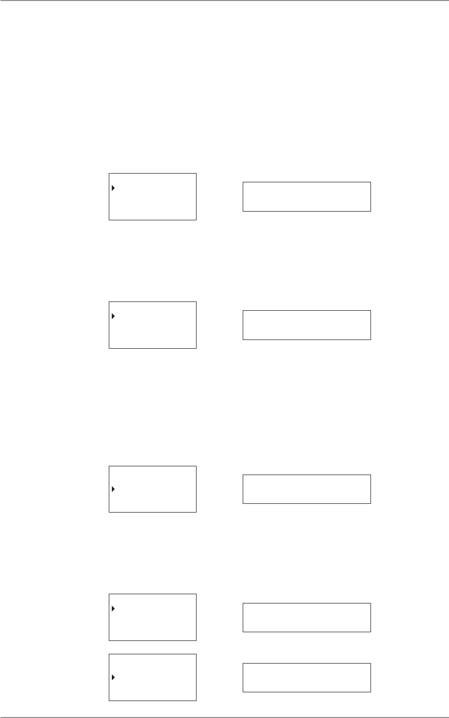
CM60 Series User Manual
09 May 2018
© 2018 Standard Communicaons Pty Ltd. All rights reserved.
47
49809-4
Content
The opons available are:
• MAIN SPK (Main speaker)
• AUX SPK (Auxiliary speaker)
Main Speaker
To access Main Speaker:
1. Select Sengs from the main menu.
2. Select Speakers.
3. Select Main Spk.
MAIN SPK
AUX SPK
Select Back main spk
To set the mute/unmute main speaker:
1. Press the A buon to select Mute to mute main speaker. Select Unmute to unmute the
speaker.
2. Press the B buon to go back to the previous menu.
MUTE
UNMUTE
Select Back mute
Auxiliary Speaker
To access Auxiliary Speaker:
1. Select Sengs from the main menu.
2. Select Speakers.
3. Select Aux Spk.
MAIN SPK
AUX SPK
Select Back aux spk
To set the mute/unmute auxiliary speaker:
1. Press the A buon to select Mute to mute the auxiliary speaker. Select Unmute to
unmute the speaker.
2. Press the B buon to go back to the previous menu.
MUTE
UNMUTE
Select Back mute
MUTE
UNMUTE
Select Back mute

CM60 Series User Manual
09 May 2018
© 2018 Standard Communicaons Pty Ltd. All rights reserved.
48
49809-4
Content
Bluetooth
The Bluetooth feature allows the radio to wirelessly connect to a compable device. The feature can
be used only by the dealer to download rmware, and update conguraon on the radio.
RADIO INFO
SPEAKERS
Select Back
bluetoothBLUETOOTH
Diagnoscs
The Diagnoscs opon allows access to view the radio’s frequency and RSSI.
To access this opon, select Diagnoscs from the main menu.
TRUNKING
SETTINGS
DIAGNOSTICS
Select Back diagnostics
There are two opons available for this feature:
• Frequency
• RSSI
Frequency
The Frequency opon displays the radio’s current frequency.
To view radio frequency details:
1. Select Diagnoscs from the main menu.
2. Select Frequency.
FREQUENCY
RSSI
Select Back frequency
The following gure is an example of the radio frequency display on the controller microphone and
local head.
167.4500MHz
Exit 167,4500mhz
Press the B buon to exit.

CM60 Series User Manual
09 May 2018
© 2018 Standard Communicaons Pty Ltd. All rights reserved.
49
49809-4
Content
RSSI
The RSSI (Received Signal Strength Indicaon) opon displays the received signal strength of the
current channel. The signal strength is expressed in decibels (dBm). The lower the dBm number, the
stronger the signal.
To view the radio RSSI:
1. Select Diagnoscs from the main menu
2. Select RSSI.
FREQUENCY
RSSI
Select Back RSSI
The gure belows is an example of the RSSI display on the controller microphone and the local head.
167.4500MHz
SITE ID: 2
-70dBm
Exit -70dbm
Press the B buon to exit.
Emergency Modes
Any programmable key can be congured to acvate the emergency mode. Depending on how the
local/remote control head, or microphones are congured, a press or a hold of the programmed key
acvates emergency mode. Figure 8 in this manual displays the emergency buon on the controller
microphone. The dealer can congure the funcon of the buon as required. Contact the dealer for
more informaon on the exact behaviour of emergency modes, and how to congure it on the radio.

CM60 Series User Manual
09 May 2018
© 2018 Standard Communicaons Pty Ltd. All rights reserved.
50
49809-4
Content
Programmable Keys Control Funcons
This secon illustrates the various control funcons that the dealer has assigned to programmable
keys on the radio. The secons below can be lled in by the dealer.
Local/Remote Control Head Programmable Funcons
Label the diagram below with the control funcons assigned to the programmable keys.
Figure 11 - Control funcons on local/remote control head
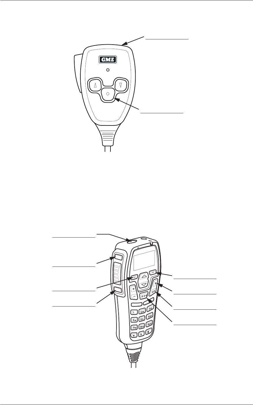
CM60 Series User Manual
09 May 2018
© 2018 Standard Communica ons Pty Ltd. All rights reserved.
51
49809-4
Content
Fist Microphone Programmable Func ons
Label the diagram below with the control func ons assigned to the programmable keys.
Figure 12 - Control func ons on fi st microphone
Controller Microphone Programmable Func ons
Label the diagram below with the control func ons assigned to the programmable keys.
Figure 13 - Control func ons on controller microphone
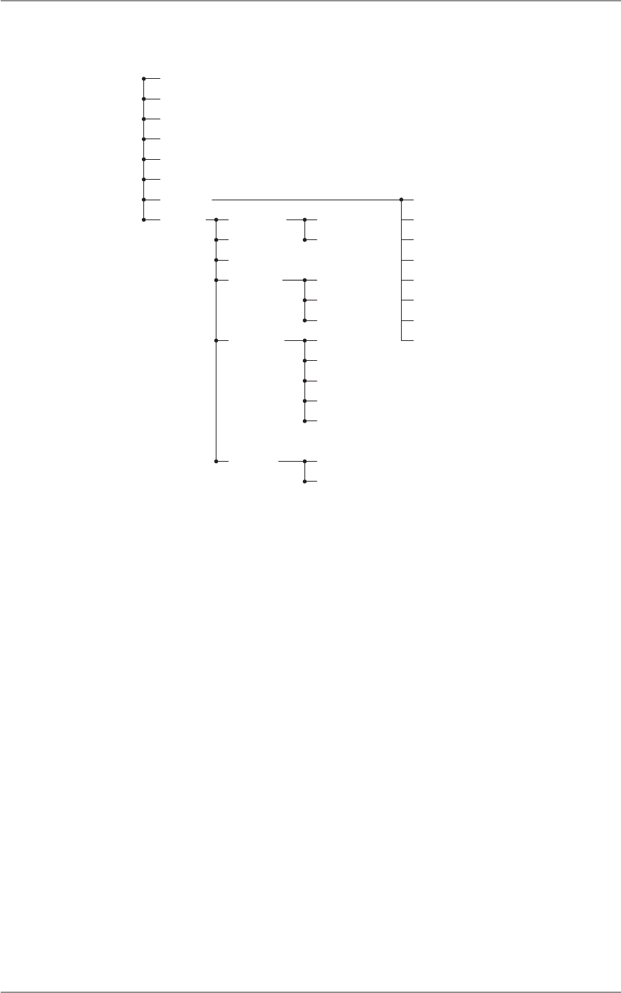
CM60 Series User Manual
09 May 2018
© 2018 Standard Communicaons Pty Ltd. All rights reserved.
52
49809-4
Content
Menu Tree - Analog
Channels
Zones
Recent Call
Recent Message
Selcall
Send DTMF
Alert Level
Channel Info
Beep Level
Key Tones
Lock Radio
Squelch Level
TX Power
Radio Info F/W Version
MAC Address
MSM Version
Serial Number
Speakers Main Speakers
Aux Speakers
Display**
MDC/SelCall ID
Services* Send Message
Send Alert
Send Status
Set Status
Status Request
Check Request
Uninhibit Request
Inhibit Request
* The ‘Services’ menu is displayed only when Digital Selcall (MDC1200) is enabled.
** The ‘Display’ menu is displayed only on the local/remote control head.

CM60 Series User Manual
09 May 2018
© 2018 Standard Communicaons Pty Ltd. All rights reserved.
53
49809-4
Content
Menu Tree - P25 Convenonal
Channels
Zones
Recent Call
Recent Message
Unit Call
Services
Alert Level
Channel Info
Beep Level
Key Tones
Lock Radio
TX Power
Phone Calls
Send Message
Send Alert
Send Status
Set Status
Status Request
Check Request
Inhibit Request
Uninhibit Request
Radio Info F/W Version
MAC Address
MSM Version
Serial Number
Speakers Main Speakers
Aux Speakers
Display*
P25 Unit ID
* The ‘Display’ menu is displayed only on the local/remote control head.
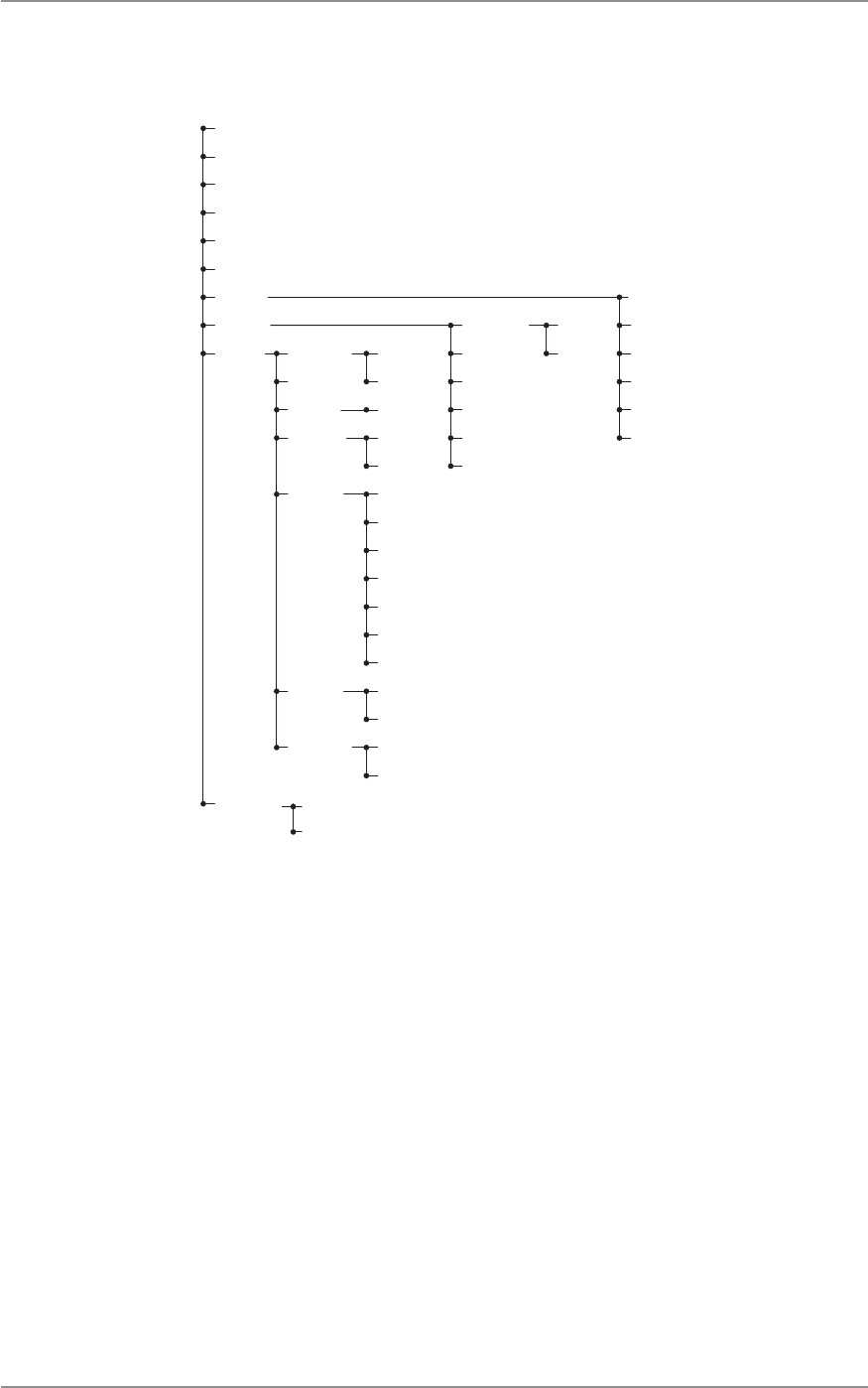
CM60 Series User Manual
09 May 2018
© 2018 Standard Communicaons Pty Ltd. All rights reserved.
54
49809-4
Content
Menu Tree - P25 Trunked
Channels
Zones
Recent Call
Recent Message
Unit Call
Services
Alert Level
Channel Info
Beep Level
Key Tones
Lock Radio
TX Power
Phone Call
Send Message
Send Alert
Send Status
Set Status
Status Request
Check Request
Radio Info
F/W Version
MAC Address
MSM Version
Serial Number
Speakers Main Speakers
Aux Speakers
Bluetooth Pair
BT Info
Display*
Trunking Force Hunt
Network Info
Radio ID
Site Name
Site Lock
Site Select
P25 Unit ID
Frequency
RSSI
Backlight
MDC/Selcall ID
Change PIN
Short
Extended
* The ‘Display’ menu is displayed only on the local/remote control head.

CM60 Series User Manual
09 May 2018
© 2018 Standard Communicaons Pty Ltd. All rights reserved.
55
49809-4
Content
Specicaons
General
Type Descripon
RF Performance Compliant with AS/NZS 4295 | ETS 300-086 | TIA-603-C
Frequency Band VHF 136 to 174MHz (Australia)
VHF: 138 to 174MHz (Canada)
VHF: 150 to 174MHz (US)
UHF LO: 400 to 480MHz (Australia)
UHF LO: 406.1 to 470MHz (Canada)
UHF LO: 406.1 to 480MHz (US)
UHF HI: 450 to 520MHz (Australia)
UHF HI: 450 to 470MHz (Canada)
UHF HI: 450 to 512MHz (US)
Number of Channels Total 2000 | P25 1072
Number of Zones 50
Channel Spacing 25kHz, 12.5kHz
Channel Steps 12.5kHz, 6.25kHz, 5kHz, 2.5kHz
Frequency Stability ±1kHz for -20°C to 60°C or -4°F to 140°F
Modulaon FM, C4FM
Antenna Impedance 50Ω
Antenna Connector BNC
Supply Voltage 13.8V negave earth
Operang Voltage Range 10.8V to 15.6V
Reverse Polarity Protecon Diode
Over Voltage Protecon 18V crowbar
Fuse 2 x 10A blade type in-line fuse
Current Consumpon RX muted 170mA | RX full audio 1A | TX 6A
Transmier
Type Descripon
Power Output 25W, 10W, 5W, 1W selectable per channel
Transmit Duty Cycle 4:1 for 25W output
Modulaon Type C4FM, FM, DC coupled, DSP audio processing
Deviaon Liming 5kHz, 2.5kHz at +20dB AF liming
TX Audio Frequency
Response
+6dB/octave, +1dB/-3dB, 300Hz to 3kHz
AF Distoron 3% below liming
TX Audio Residual Noise and
Hum
-40dB
Spurious Emissions -36dBm
Adjacent Channel Power -60dBc
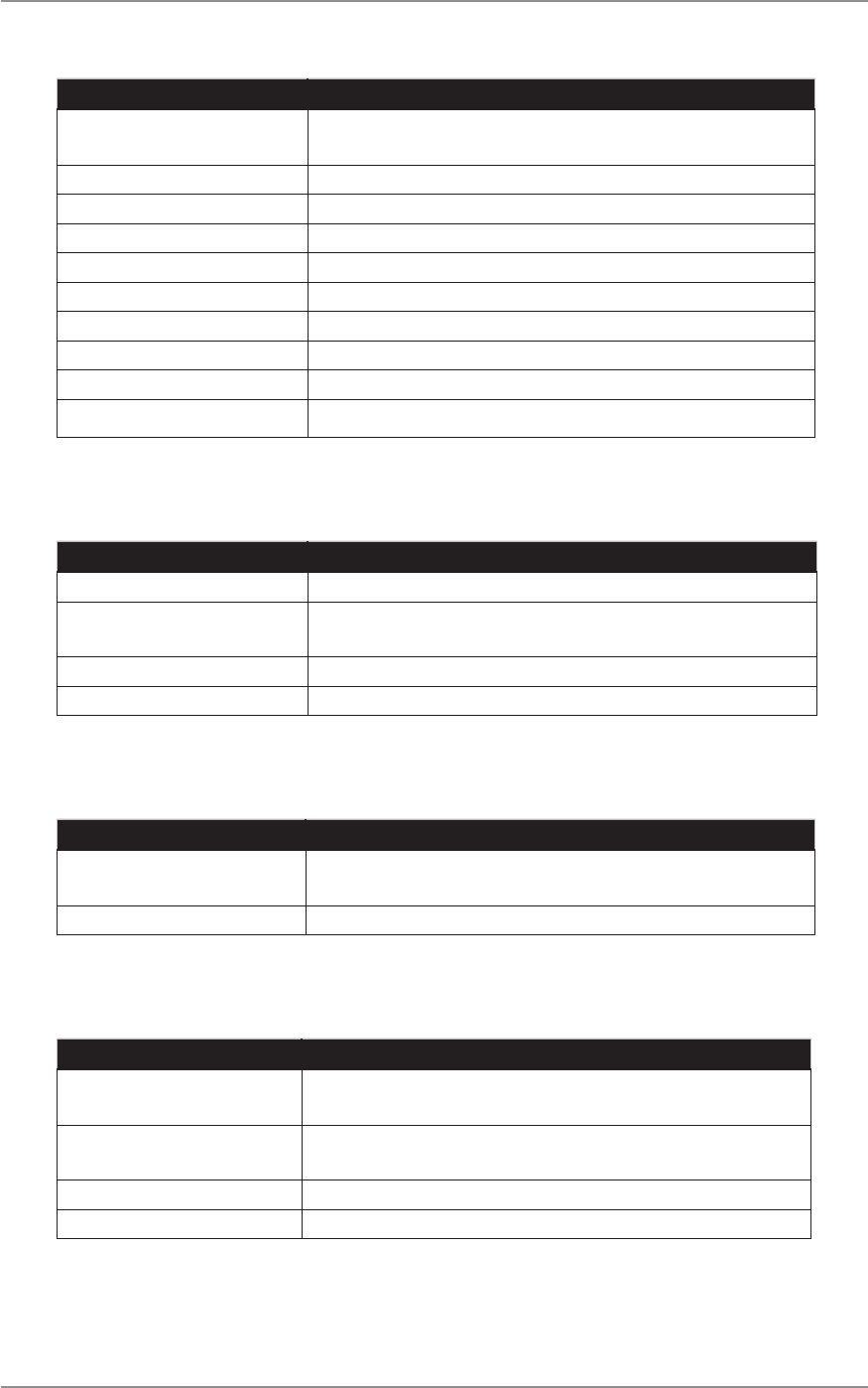
CM60 Series User Manual
09 May 2018
© 2018 Standard Communicaons Pty Ltd. All rights reserved.
56
49809-4
Content
Receiver
Type Descripon
Circuit Type Double Conversion Superheterodyne, DC coupled, DSP audio
processing
IF Frequencies 21.4MHz (VHF) | 38.85MHz (UHF), 450 kHz
Analog Sensivity -122dBm for 12dB SINAD unweighted
Digital Sensivity -122dBm C4FM for 5% BER
Adjacent Channel Selecvity 60dB
Spurious Rejecon 75dB
Intermodulaon Rejecon 75dB
Blocking 100dB
RF Switching Bandwidth VHF 38MHz | UHF 70MHz
Conducted Spurious Emissions -80dBm
Audio
Type Descripon
RX Audio Frequency Response +6dB/octave, +1dB/-3dB, 300Hz to 3kHz
RX Audio Residual Noise and
Hum
-40dB
Audio Rated Power - Radio 3W into 4Ω
Audio Rated Power - UIC600 2W into 8Ω
Mechanical
Type Descripon
Dimensions 29mm (H) x 127mm (W) x 163mm (D)
1.14”(H) x 5” (W) x 6.41”(D)
Weight 620g
Environmental
Type Descripon
Operang Temperature Range -30°C to 60°C
-22°F to 140°F
Storage Temperature Range -30°C to 70°C
-22°F to 158°F
Shock and Vibraon MILSPEC 810
Ingress Protecon Rang IP54

1300 463 463 gmeprofessional.com
A division of Standard Communications Pty Ltd.
Head O ce: PO Box 96, Winston Hills, NSW 2153, Australia.
New Zealand: PO Box 58446 Botany, Auck land, 2163, NZ. T: (09) 274 0955.
All international enquiries email: export@gme.net.au
WHEREVER LIFE TAKES YOU, TAKE GME.