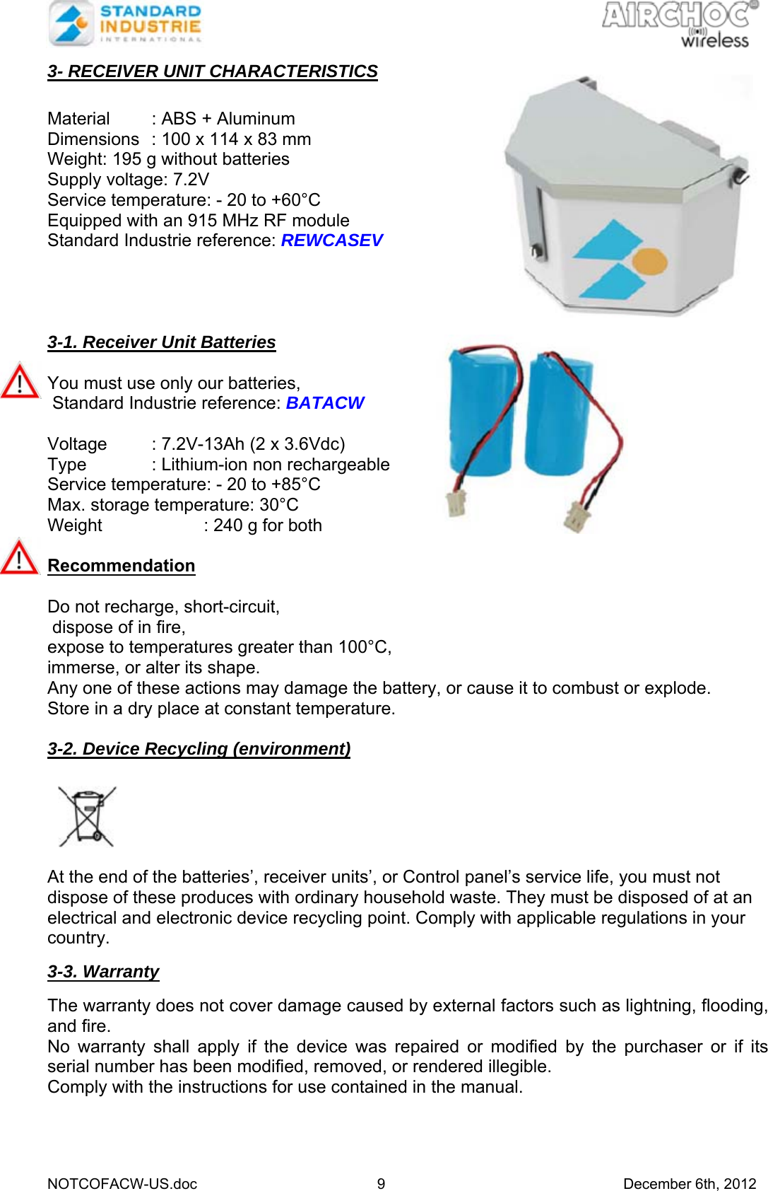
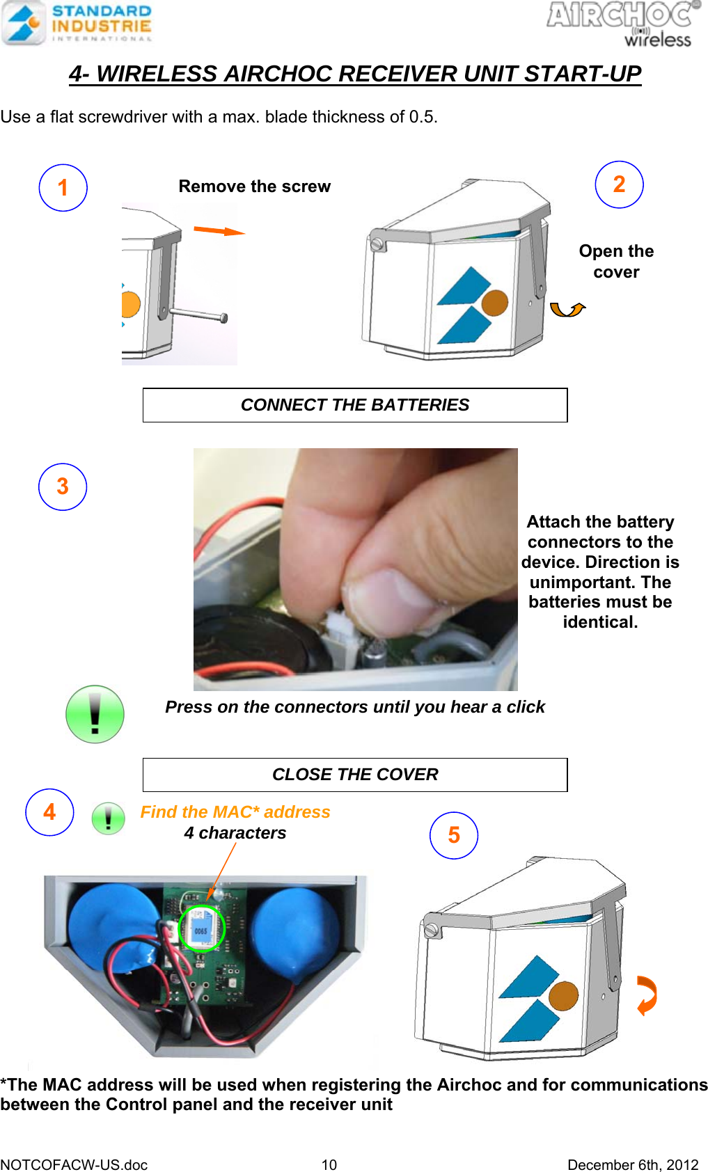
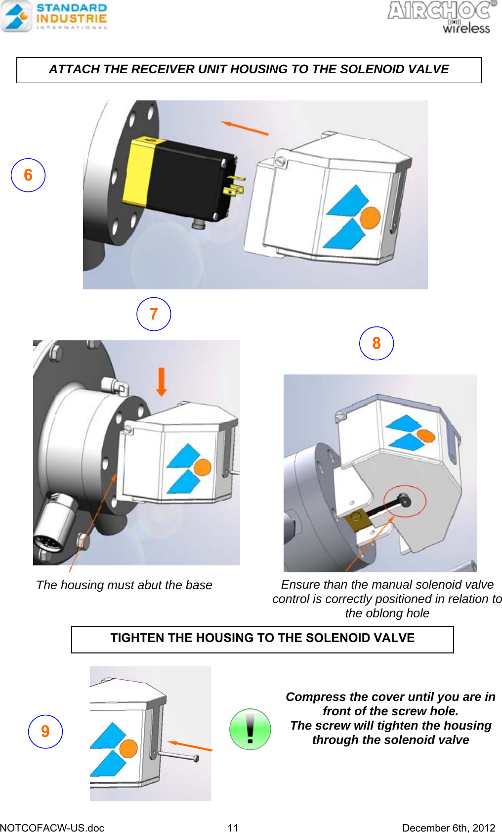
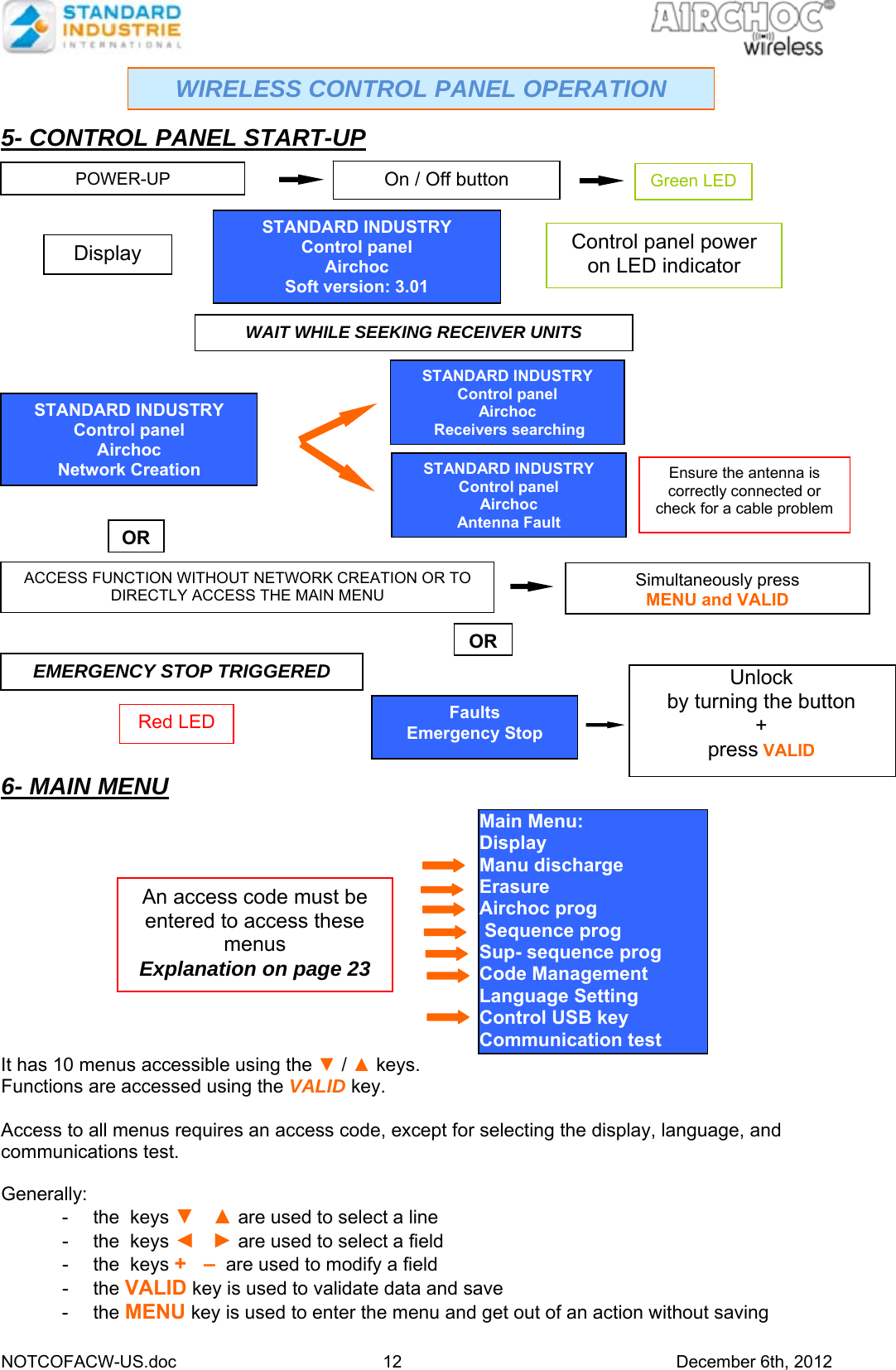
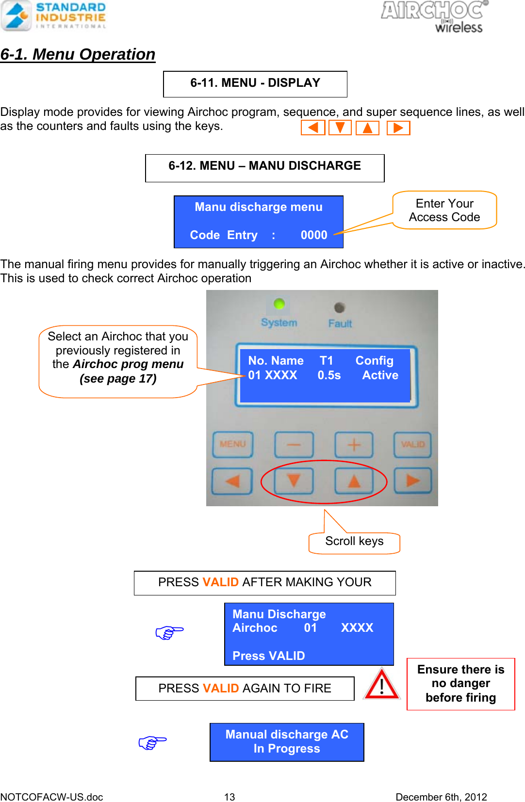
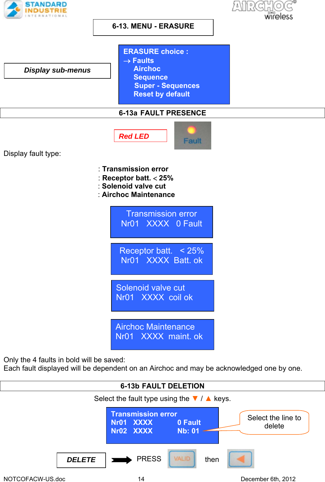
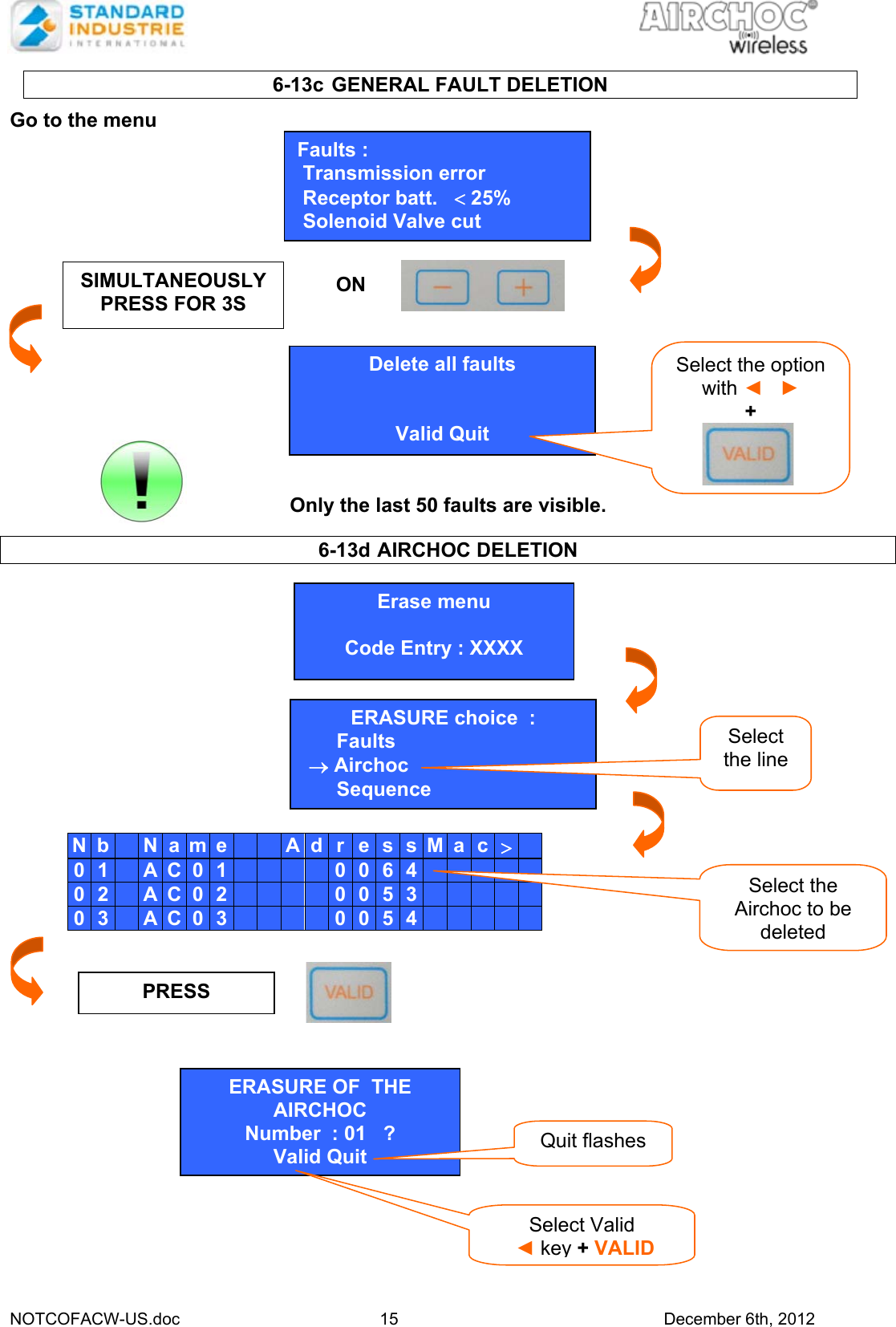
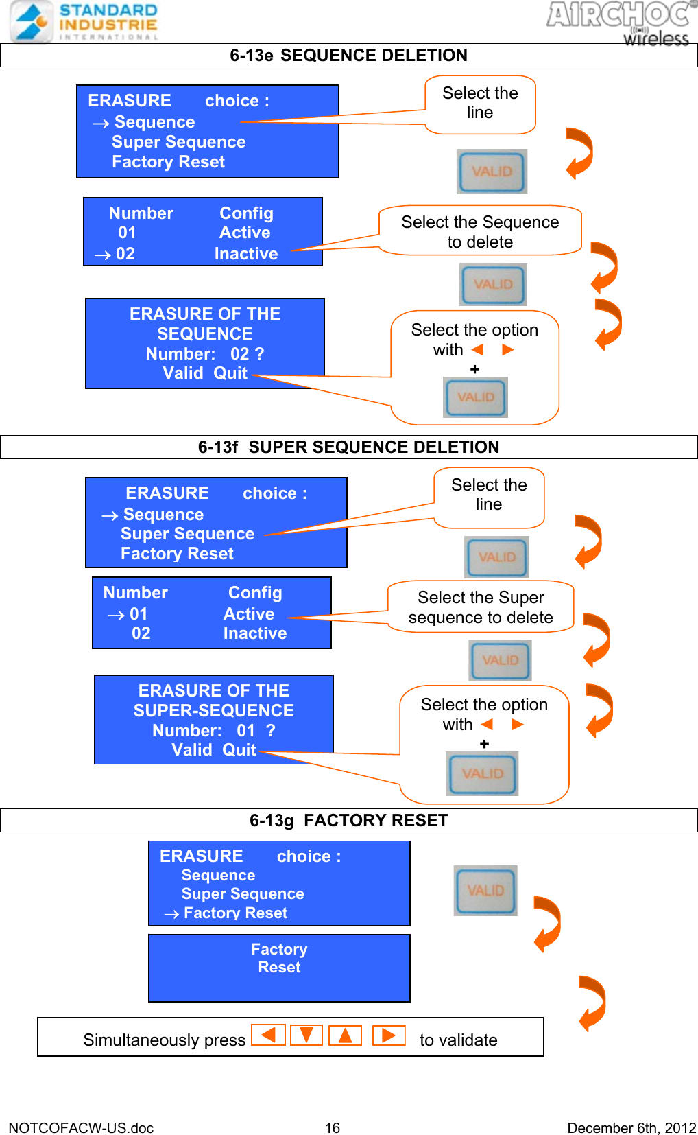
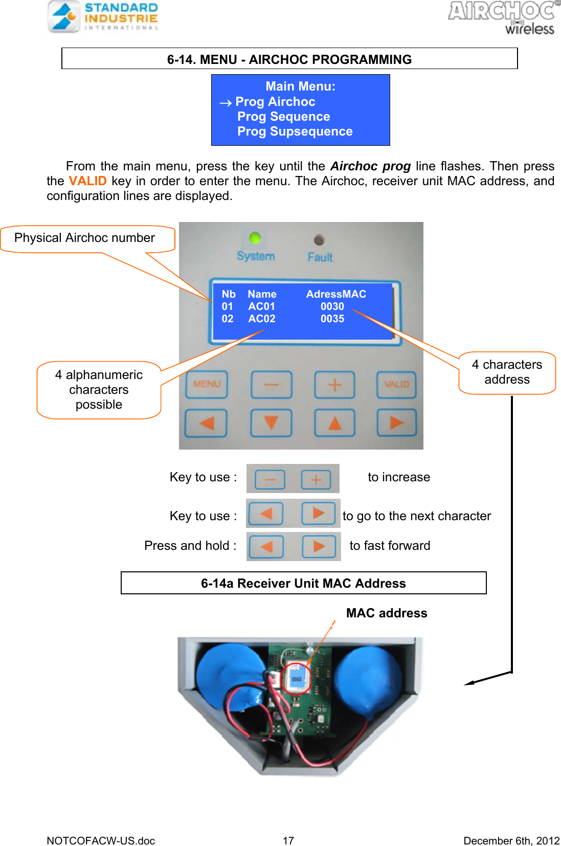
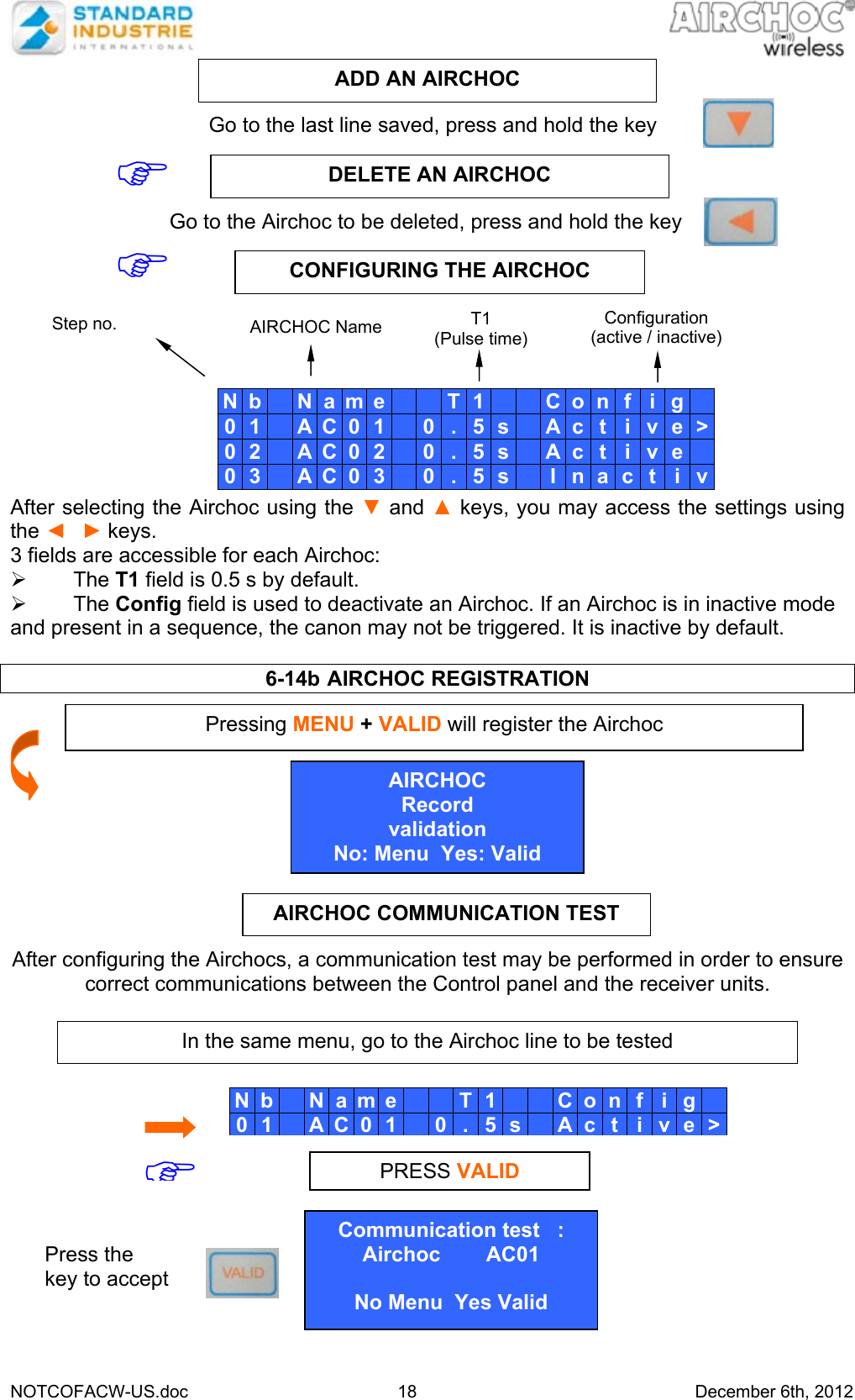
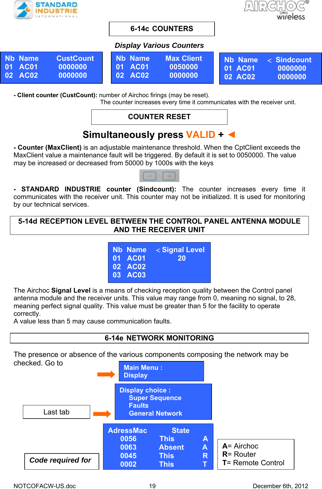
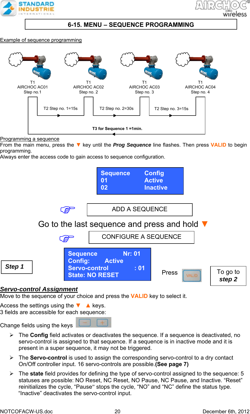
Standard Industrie COFACWCA CONTROL PANEL FOR AIRCHOC WIRELESS APPLICATION User Manual NOTCOFACW US H1
Standard Industrie CONTROL PANEL FOR AIRCHOC WIRELESS APPLICATION NOTCOFACW US H1
UserManual.wiki
>
Standard Industrie
>
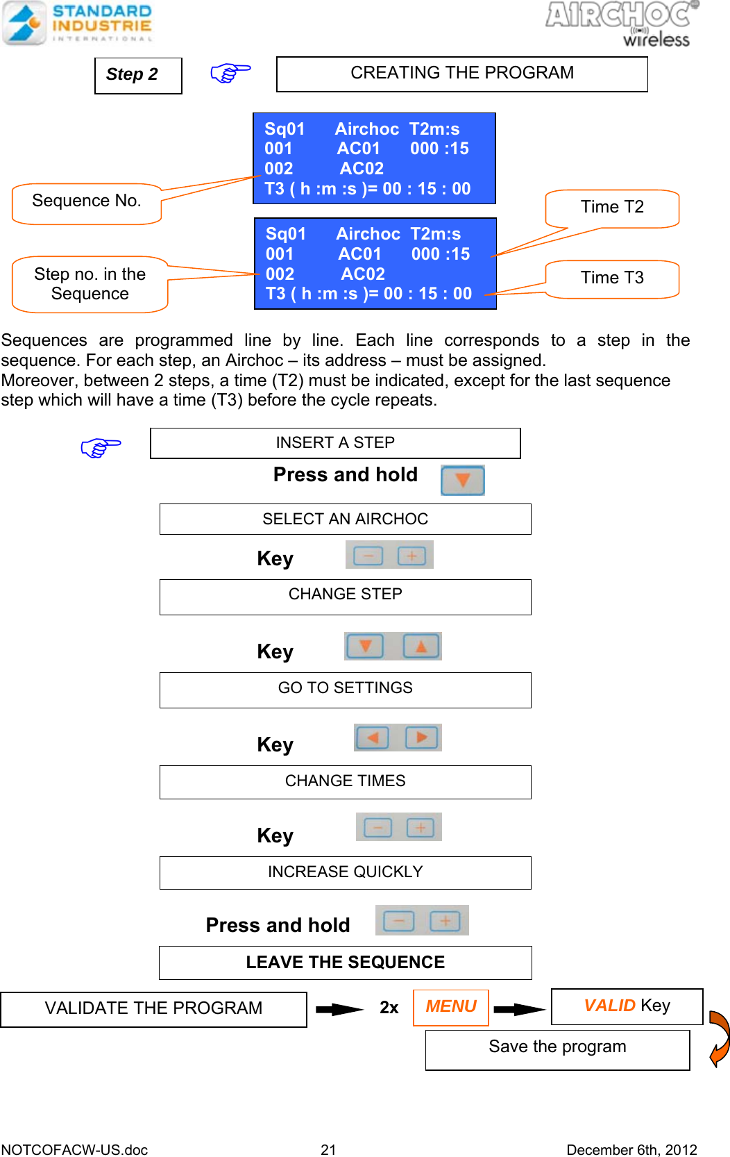
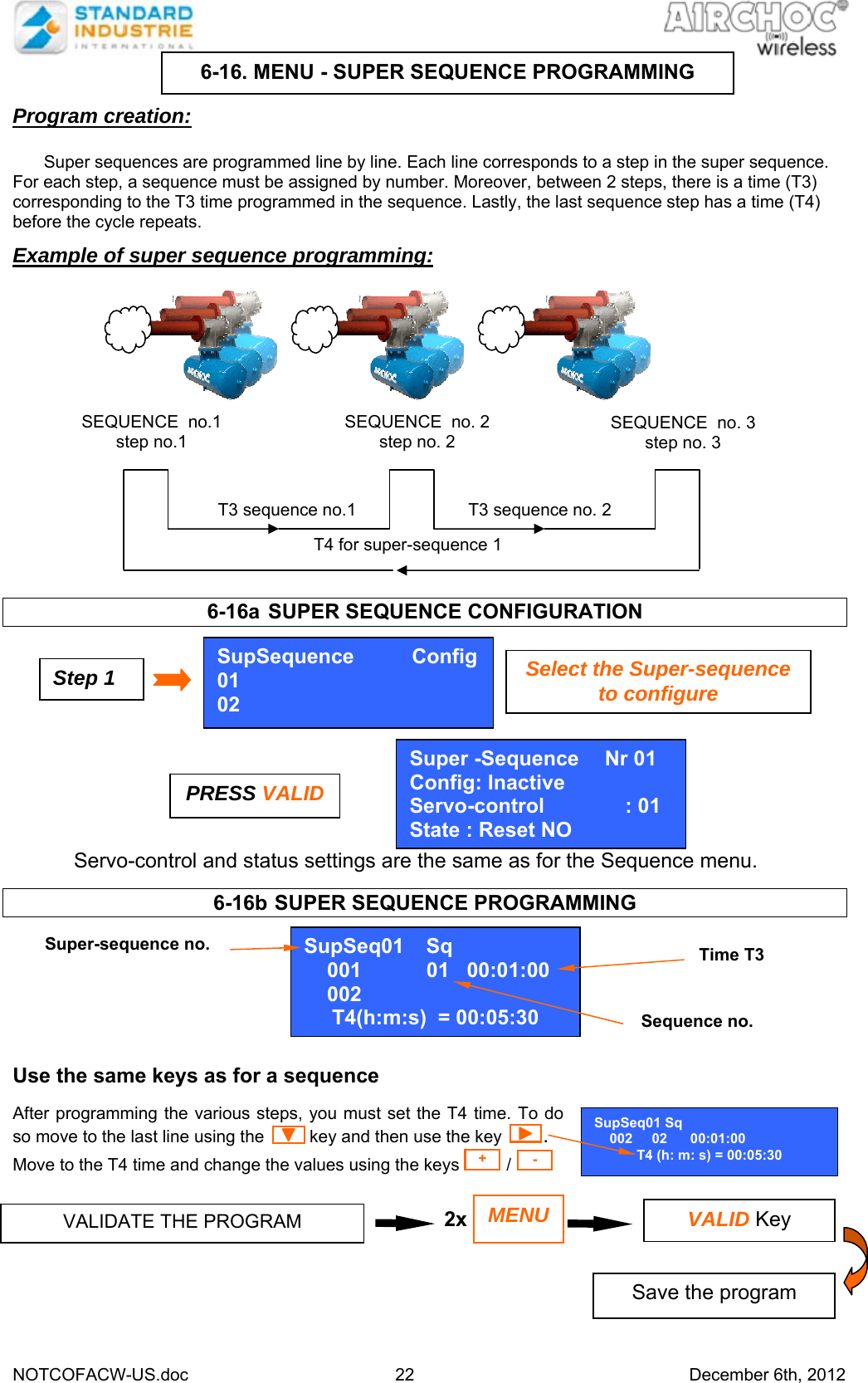
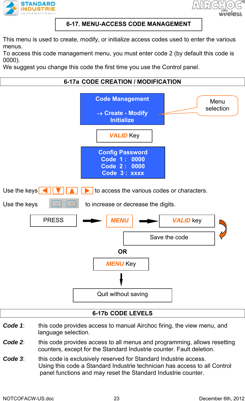
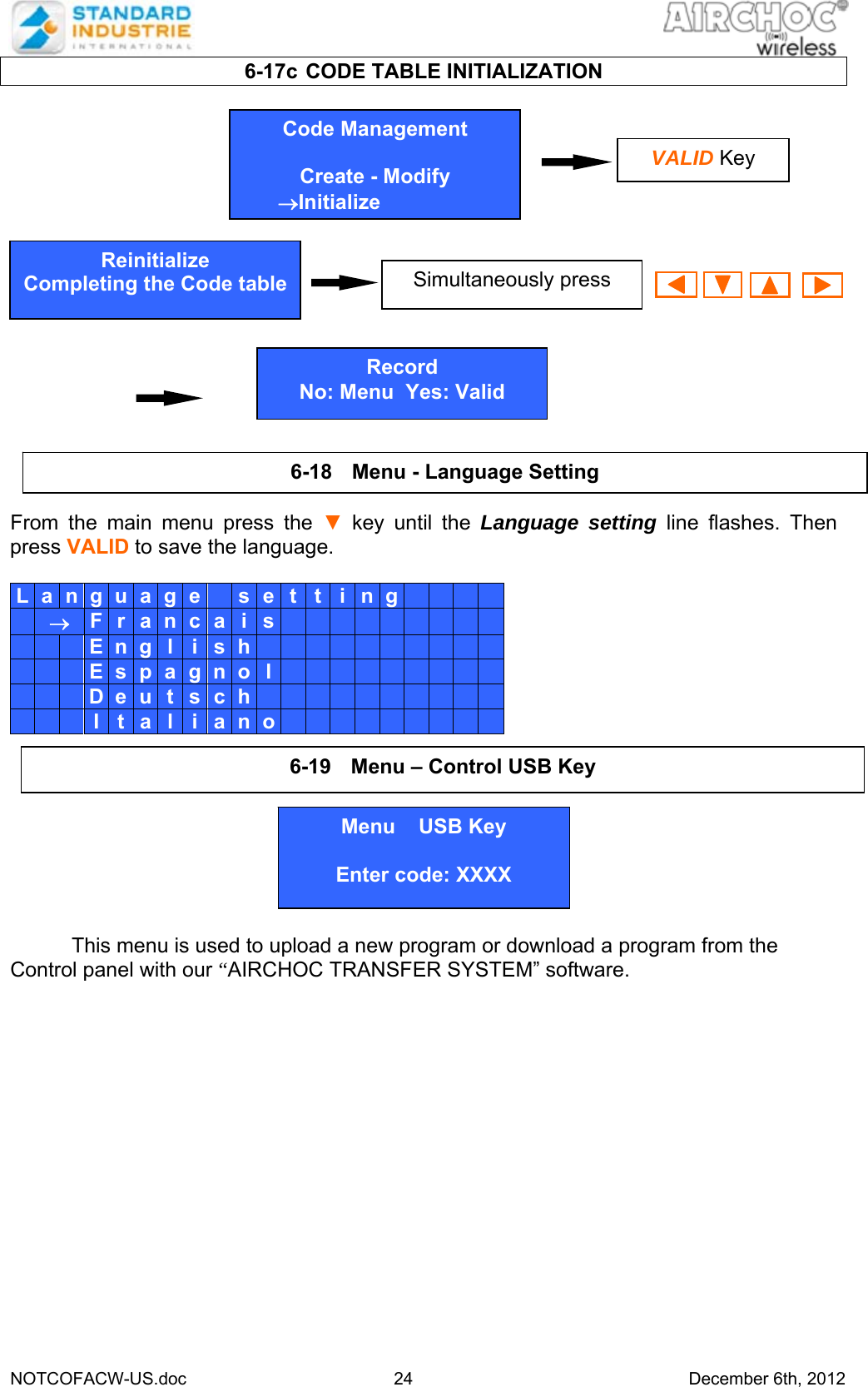
COFACWCA User Manual
User Manual
Navigation menu
Upload a User Manual
Namespaces
Wiki Guide
HTML
PDF
Info
Views
User Manual
Discussion / Help
Navigation