Standard Industrie COFACWCA CONTROL PANEL FOR AIRCHOC WIRELESS APPLICATION User Manual NOTCOFACW US H1
Standard Industrie CONTROL PANEL FOR AIRCHOC WIRELESS APPLICATION NOTCOFACW US H1
User Manual
NOTCOFACW-US.doc 1 December 6th, 2012
Produced on: December 20th, 2012
By: DESIGN OFFICE
Checked on:
By: BOISLEUX.M
Signature:
TECHNICAL
INSTRUCTIONS
Revision Level: H1
NOTCOFACW-US Date: December 6th, 2012
HEAD OFFICE- Standard Industrie : 139-141 rue du Luxembourg-BP50207 59054
ROUBAIX CEDEX 1- FRANCE
+33 (0)3 20 28 32 32 / @ : info@standard-industrie.com

NOTCOFACW-US.doc 2 December 6th, 2012
1- PRINCIPLE OF AIRCHOC WIRELESS Page 3
2- AIRCHOC WIRELESS TRANSMITTER INSTALLATION Page 3
2-1 Control panel fixation Page 3
2-2 Antenna Connection Page 3
2-3 Antenna Placement Page 3
2-4 Control panel Presentation Page 4
2-5 Control panel Electrical Hook-up Page 5
2-51 Electrical Characteristics Page 5
2-52 Environmental Characteristics Page 6
2-53 Additional Exterior Characteristics Page 6
2-54 Explanation of different symbol on the labels Page 6
2-55 Switching device Page 6
2-54 Control panel Circuit Board Operation Page 6
2-56 Instructions Page 6
2-57 Control panel circuit board operation Page 7
2-58 Servo-control Hook-up Page 7
2-59 Alarm, Cycle, and Fault Relay Output Page 8
2-60 Changing fuses Page 8
3-RECEIVER UNIT CHARACTERISTICS Page 9
3-1 Receiver Unit Batteries Page 9
3-2 Recycling Page 9
3-3 Warranty Page 9
4-WIRELESS RECEIVER UNIT START-UP Page 10
5- CONTROL PANEL START-UP Page 12
6- MAIN MENU Page 12
6-1 Menu Operation Page 13
6-11 Display Menu Page 13
6-12 Manu Discharge Page 13
6-13 Erasure Menu Page 14
6-13a Fault Presence Page 14
6-13b Fault Deletion Page 15
6-13c General Fault Deletion Page 15
6-13d Airchoc Deletion Page 15
6-13e Sequence Deletion Page 16
6-13f Super Sequence Deletion Page 16
6-13g Factory Reset Page 16
6-14 Airchoc Programming Menu Page 17
6-14a Receiver Unit MAC Address Page 17
6-14b Airchoc Registration Page 18
6-14c Counters Page 19
6-14d Reception Level between Control panel and Receiver Unit Page 19
6-14e Network Monitoring Page 19
6-15 Sequence Programming Menu Page 20
6-16 Super Sequence Programming Menu Page 22
6-16a Super Sequence Configuration Page 22
6-16b Super Sequence Programming Page 22
6-17 Access Code Management Page 23
6-17a Code Creation / Modification Page 23
6-17b Code Level Page 23
6-17c Code Table Initialization Page 24
6-18 Language Setting Menu Page 24
6-19 Control USB Key Menu Page 24
6-20a Save Program Page 25
6-20b Upload Program to Control panel Page 25
6-20c Update Control panel Version Page 26
6-21 Communication Test Page 26
7-CHANGING RECEIVER UNIT BATTERIES Pages 27 to 30
CONTENTS
NOTCOFACW-US.doc 3 December 6th, 2012
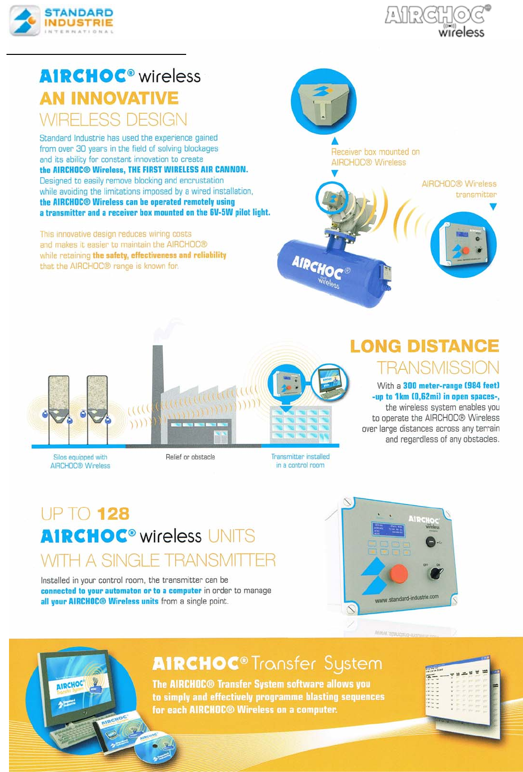
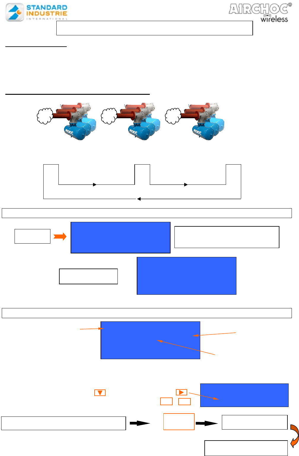
1- Principle of Airchoc Wireless
NOTCOFACW-US.doc 4 December 6th, 2012
2- AIRCHOC WIRELESS TRANSMITTER INSTALLATION
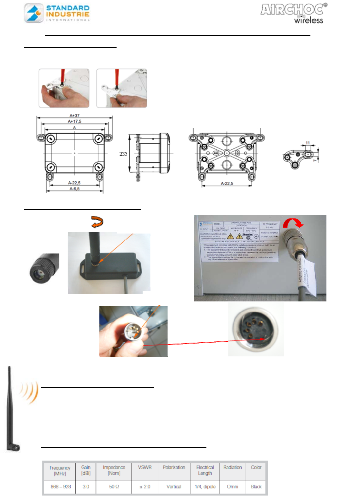
2-1. Control panel fixation
Attachment lugs are provided to mount the control panel on a wall.
2-2. Antenna Module Connection
NB. The antenna module is provided with 20 m of cable. If additional length is required,
please contact us.
2-3. Antenna Module Placement
We suggest placing the antenna as high as possible in order to radiate towards the
receiver unit and obtain better reception.
Communication between the transmitter Control panel and the receiver units takes
place by means of this antenna module.
This antenna module is sealed and may be installed outdoors.
2-31 Wireless external antenna characteristics
Standard Industrie Reference : COFANTENNA
65
Set of 4 brackets
. Preserves the protection index
. Possibility of vertical or horizontal mounting
. kit consisting of 4 brackets + screws
brackets (internal dimensions)
Screw the antenna
Screw the antenna connector to the box
presence of a label
keyed
A=385
NOTCOFACW-US.doc 5 December 6th, 2012
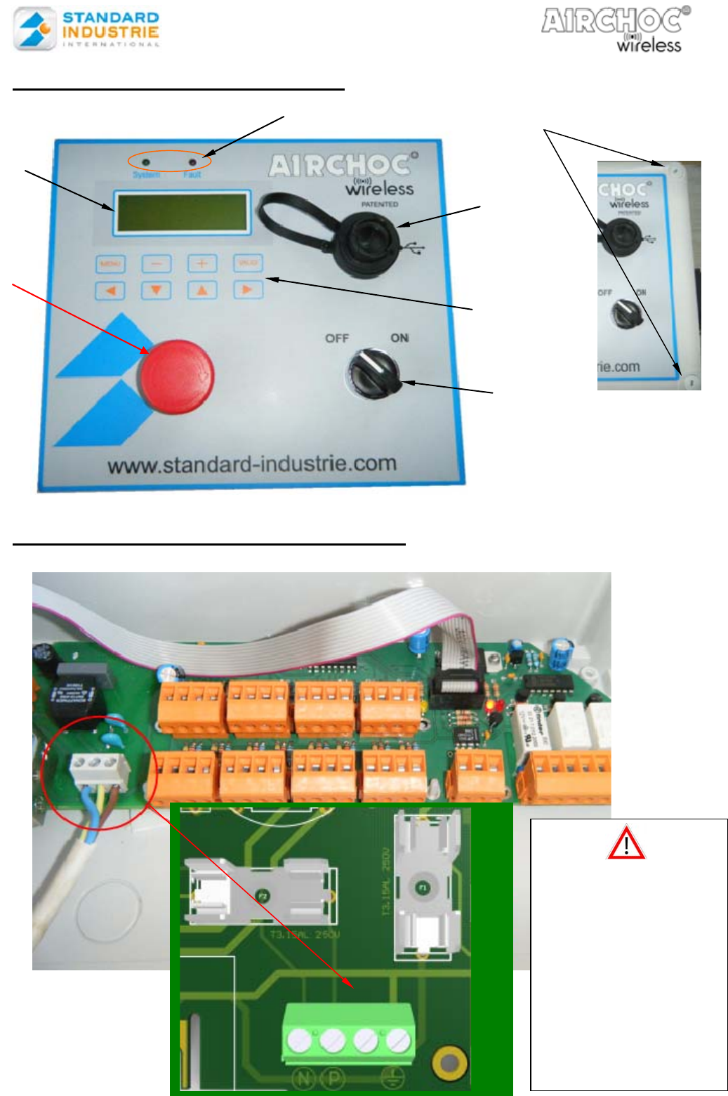
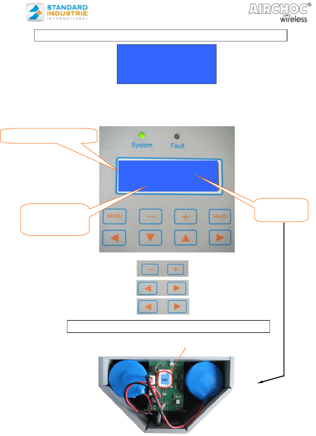
2-4. Control panel Presentation
2-5. Control panel Electrical Hook-up
White terminal
block
Emergency
stop button
Start / Stop
button
Display
LED indicators
Keyboard
USB socket
Release to
open the
Control panel
The insulation of the
conductors from the
circuits with hazardous
voltage and the other
circuits need to be
insulated by
double/reinforced
insulation for 300V
outside and inside the
equipment and to
accessible parts
NOTCOFACW-US.doc 6 December 6th, 2012
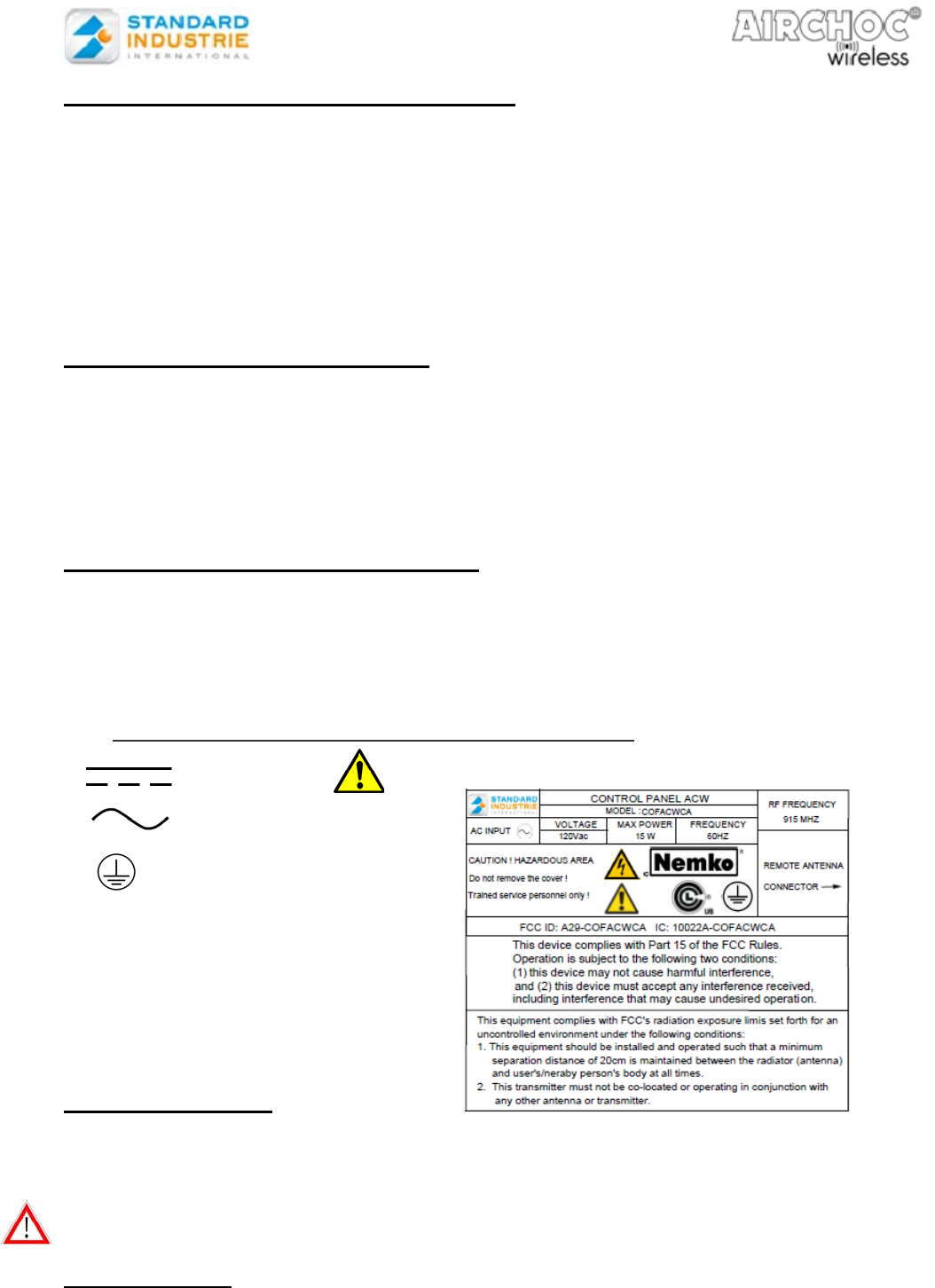
2-51. Control panel Electrical Characteristics
-Control panel universal supply voltage 120Vac
-Frequency 60 Hz
-Consumption 15W Max
-Protection, can withstand 105% of the initial power and the power source automatically cuts-off and
turns back on.
- If there is a power surge, the power source automatically cuts-off and turns back on after the repair.
- RF transmission module - 915 MHz as per IEEE 802.15.4 -2003/2006
2-52. Environmental characteristics:
- Protection Index: IP66 IK 08
- Service temperature:
- Humidity :
- Max altitude
- Pollution degree
Minimum: -10°C
Maximum: +70°C
no more than 80%
e.g up to 2000 m
2
- Material : Polycarbonate UL
2-53. Additional exterior Characteristics :
2-54.Explanation of the different symbols on the labels :
Direct current
Alternating current
2-55. Switching device :
The control panel is permanently connected to building installation, the installer must provide a
current isolation device, easy accessible to operator and marked as disconnecting device to use in
case of intervention in the control panel.
Attention : it is forbidden to clean the control panel in the high-pressure water.
The protection is impaired if equipment is used in a manner not specified by the
manufacturer.
2-56.Instructions :
Changes or modifications not expressly approved by Standard Industrie could void the user's
authority to operate the equipment.
This equipment has been tested and found to comply with the limits for a Class B digital device,
pursuant to part 15 of the FCC Rules. These limits are designed to provide reasonable protection
against harmful interference in a residential installation. This equipment generates, uses and can
- Operator interface: - 4 line LCD backlit display of 20 characters each
- 8-key keyboard
- Indicator LED:
- system (system operational)
- fault (fault detected)
- Front USB (software update and program upload)
Earth
The user must disconnect the control panel before access to the fuse.
- A connection to the earth of the control panel is required
- Electric cable used for connectin
g
have to be in accordance with the standard IEC 60320-1
,
60227
NOTCOFACW-US.doc 7 December 6th, 2012
radiate radio frequency energy and, if not installed and used in accordance with the instructions,
may cause harmful interference to radio communications. However, there is no guarantee that
interference will not occur in a particular installation. If this equipment does cause harmful
interference to radio or television reception, which can be determined by turning the equipment off
and on, the user is encouraged to try to correct the interference by one or more of the following
measures:
—Reorient or relocate the receiving antenna.
—Increase the separation between the equipment and receiver.
—Connect the equipment into an outlet on a circuit different from that to which the receiver is
connected.
—Consult the dealer or an experienced radio/TV technician for help.
This portable equipment with it’s antenna complies with FCC’s radiation exposure limits set forth for
an uncontrolled environment. To maintain compliance, follow the instructions below :
1. This transmitter must not be co-located or operating in conjunction with any other antenna or
transmitter.
2. Avoid direct contact to the antenna, or keep contact to a minimum while using this
equipment.
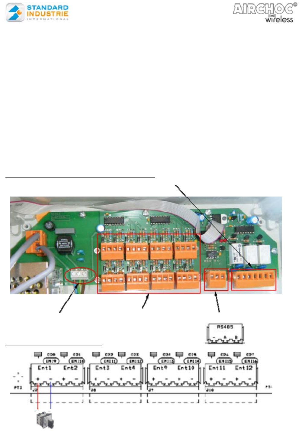
2-57. Control panel Circuit Board Operation
2-58. Servo-control hook-up
There are 16 servo-control inputs named Ent1, Ent2, etc. Normally open (NO) or normally
closed (NC) dry contacts may be connected to it. These contacts may come from various systems
(selector switch, sensor, automation output...). When programming a sequence, a number may be
assigned to the servo-control that will start the sequence. See page 20
A sequence may therefore be started by the selected servo-control input number. If you do not want
a servo-control, you must select INACTIVE in the selection
Control panel Power
Source Terminal Block
16 servo-control inputs RS485
Alarm, Cycle, and Fault Relay Output
Ent1 Ent2 Ent3 Ent4 Ent9 Ent10 Ent11
Ent12
Ent5 Ent6 Ent7 Ent8 Ent13
Ent14 Ent15 Ent16
NOTCOFACW-US.doc 8 December 6th, 2012
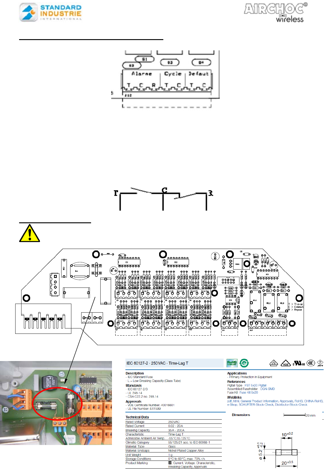
2-59. Alarm, Cycle, and Fault Relay Output
Relays used by these outputs:
-1 contact (NO and NC) for the alarm (emergency stop output).
-2 NO contacts for Cycle (operational report output), Fault (fault output).
-These outputs must be correctly configured based on the items connected to their terminals (sirens,
flashing light, automation input...). An external power source is required for sirens, flashing lights...
The maximum switching current and voltage of Alarm, Cycle and fault relays
Alarm : 6A-240 Vac, Cycle and fault relays : 8A-240 Vac
2-60. Changing fuses
Normally closed (NC) contact
Normally open (NO) contact
T: Working
C: Common
R: Rest
F1
F2
Fuse description
Two identical fuses
The user must disconnect the control panel before access to the fuse.
The fuses cuts the phase of 110Vac/240Vac and 12VDC after power supply Meanwell
NOTCOFACW-US.doc 9 December 6th, 2012
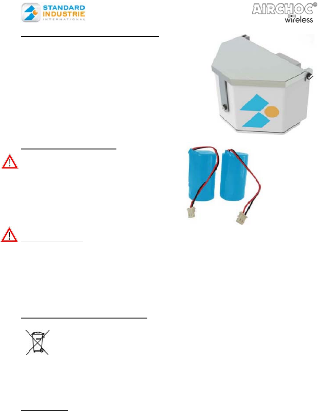
3- RECEIVER UNIT CHARACTERISTICS
Material : ABS + Aluminum
Dimensions : 100 x 114 x 83 mm
Weight: 195 g without batteries
Supply voltage: 7.2V
Service temperature: - 20 to +60°C
Equipped with an 915 MHz RF module
Standard Industrie reference: REWCASEV
3-1. Receiver Unit Batteries
You must use only our batteries,
Standard Industrie reference: BATACW
Voltage : 7.2V-13Ah (2 x 3.6Vdc)
Type : Lithium-ion non rechargeable
Service temperature: - 20 to +85°C
Max. storage temperature: 30°C
Weight : 240 g for both
Recommendation
Do not recharge, short-circuit,
dispose of in fire,
expose to temperatures greater than 100°C,
immerse, or alter its shape.
Any one of these actions may damage the battery, or cause it to combust or explode.
Store in a dry place at constant temperature.
3-2. Device Recycling (environment)
At the end of the batteries’, receiver units’, or Control panel’s service life, you must not
dispose of these produces with ordinary household waste. They must be disposed of at an
electrical and electronic device recycling point. Comply with applicable regulations in your
country.
3-3. Warranty
The warranty does not cover damage caused by external factors such as lightning, flooding,
and fire.
No warranty shall apply if the device was repaired or modified by the purchaser or if its
serial number has been modified, removed, or rendered illegible.
Comply with the instructions for use contained in the manual.
NOTCOFACW-US.doc 10 December 6th, 2012
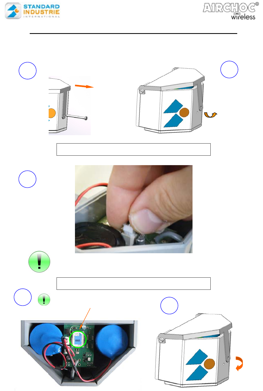
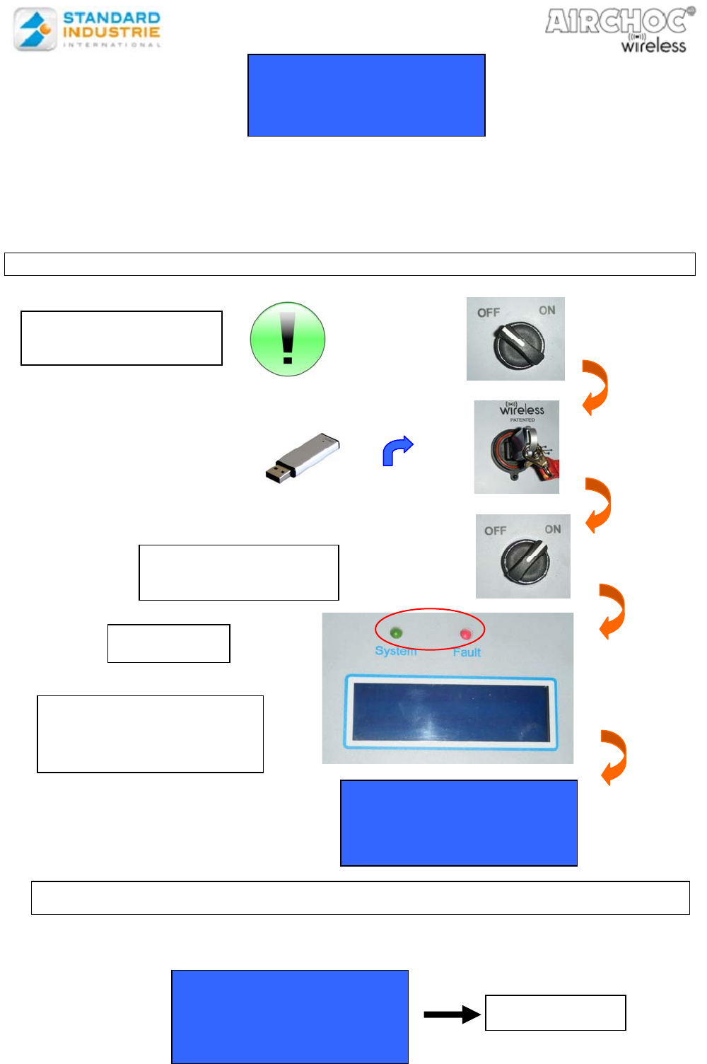
4- WIRELESS AIRCHOC RECEIVER UNIT START-UP
Use a flat screwdriver with a max. blade thickness of 0.5.
Press on the connectors until you hear a click
*The MAC address will be used when registering the Airchoc and for communications
between the Control panel and the receiver unit
CONNECT THE BATTERIES
CLOSE THE COVER
3
Remove the screw
Open the
cover
1 2
Attach the battery
connectors to the
device. Direction is
unimportant. The
batteries must be
identical.
4
5
Find the MAC* address
4 characters
NOTCOFACW-US.doc 11 December 6th, 2012
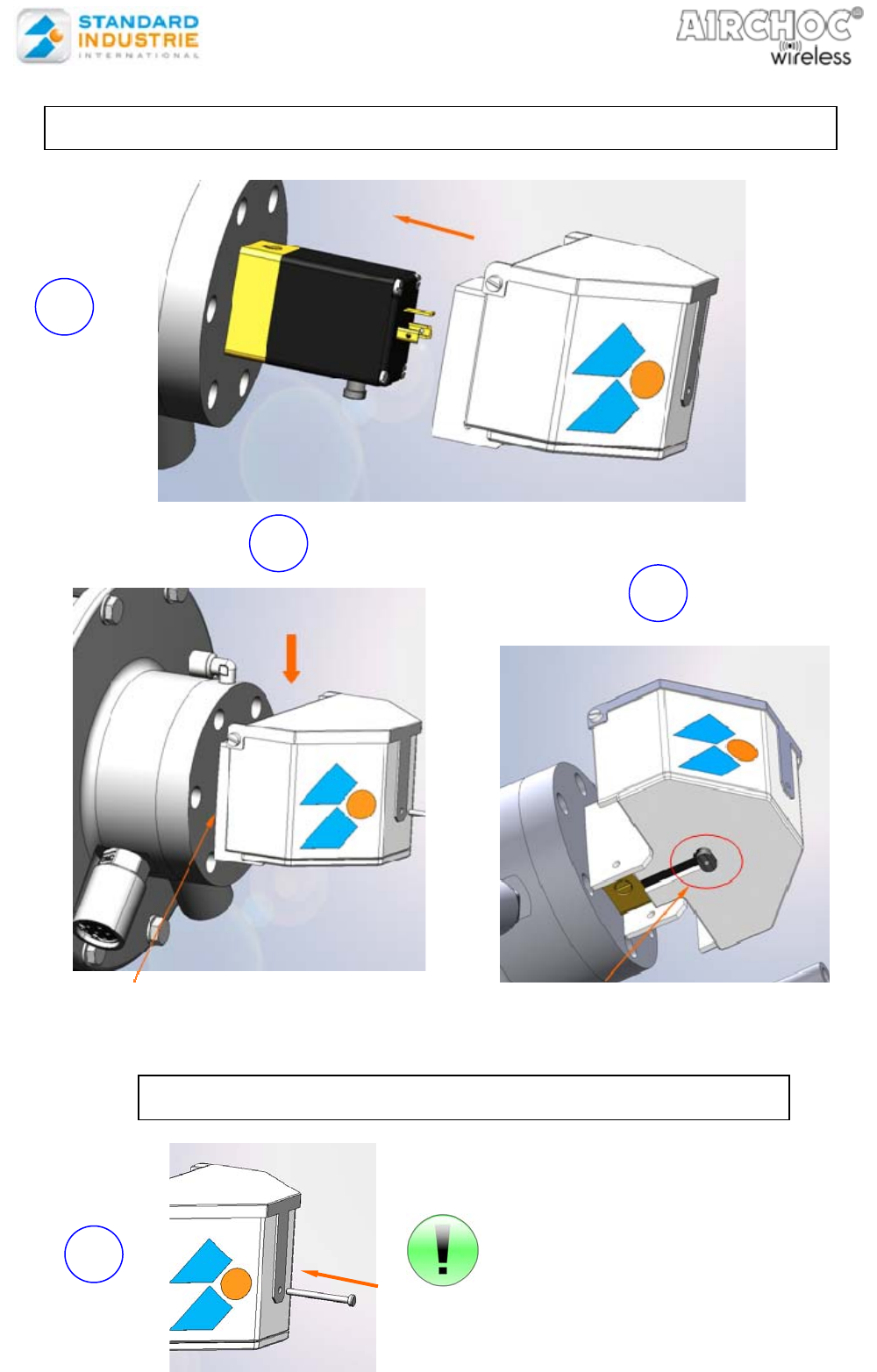
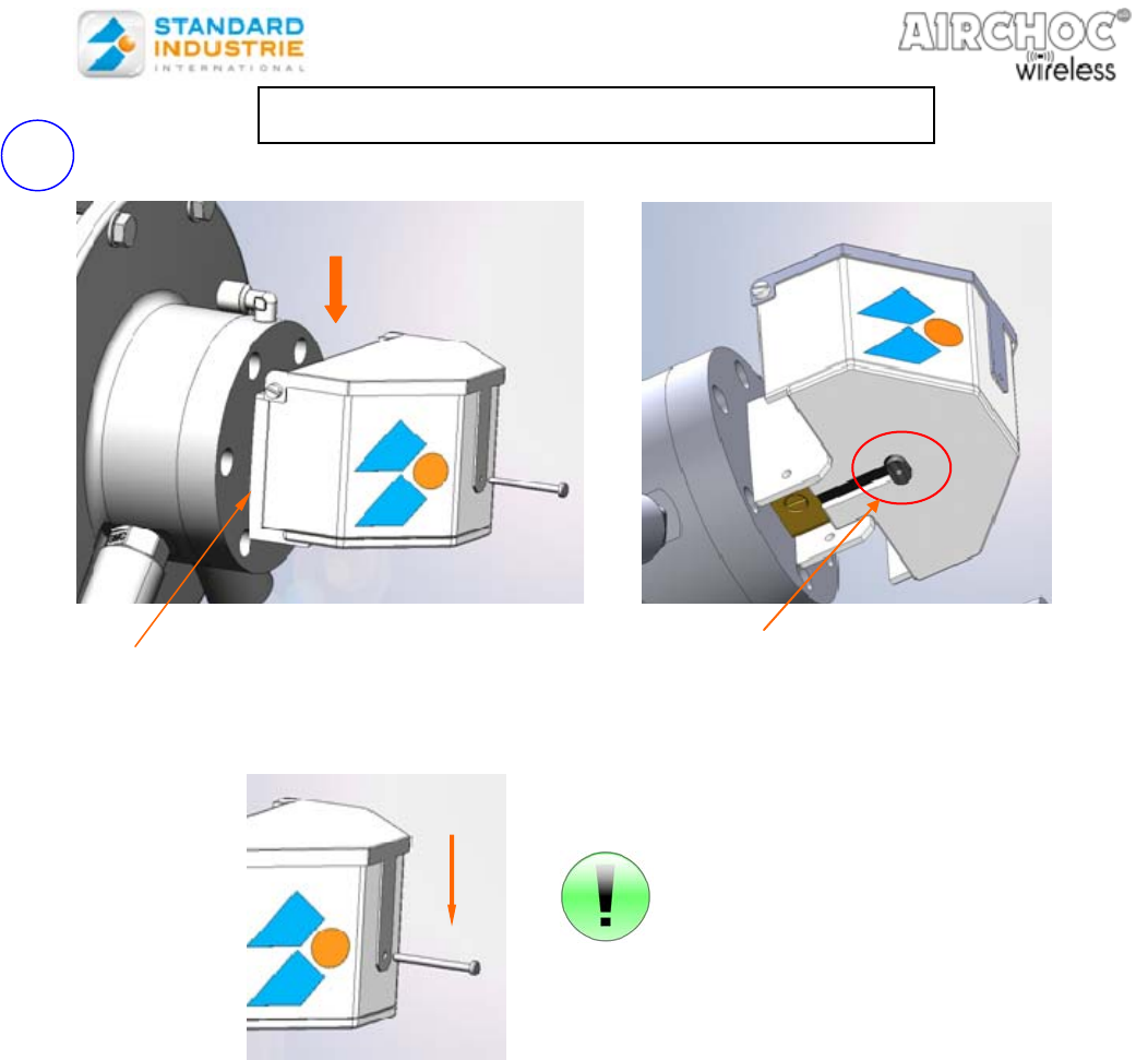
The housing must abut the base Ensure than the manual solenoid valve
control is correctly positioned in relation to
the oblong hole
6
7
8
ATTACH THE RECEIVER UNIT HOUSING TO THE SOLENOID VALVE
TIGHTEN THE HOUSING TO THE SOLENOID VALVE
Compress the cover until you are in
front of the screw hole.
The screw will tighten the housing
through the solenoid valve
9
NOTCOFACW-US.doc 12 December 6th, 2012
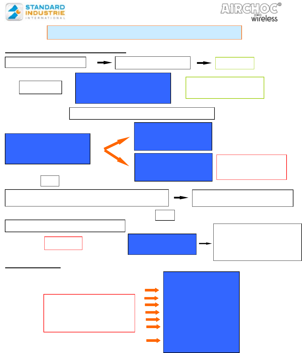
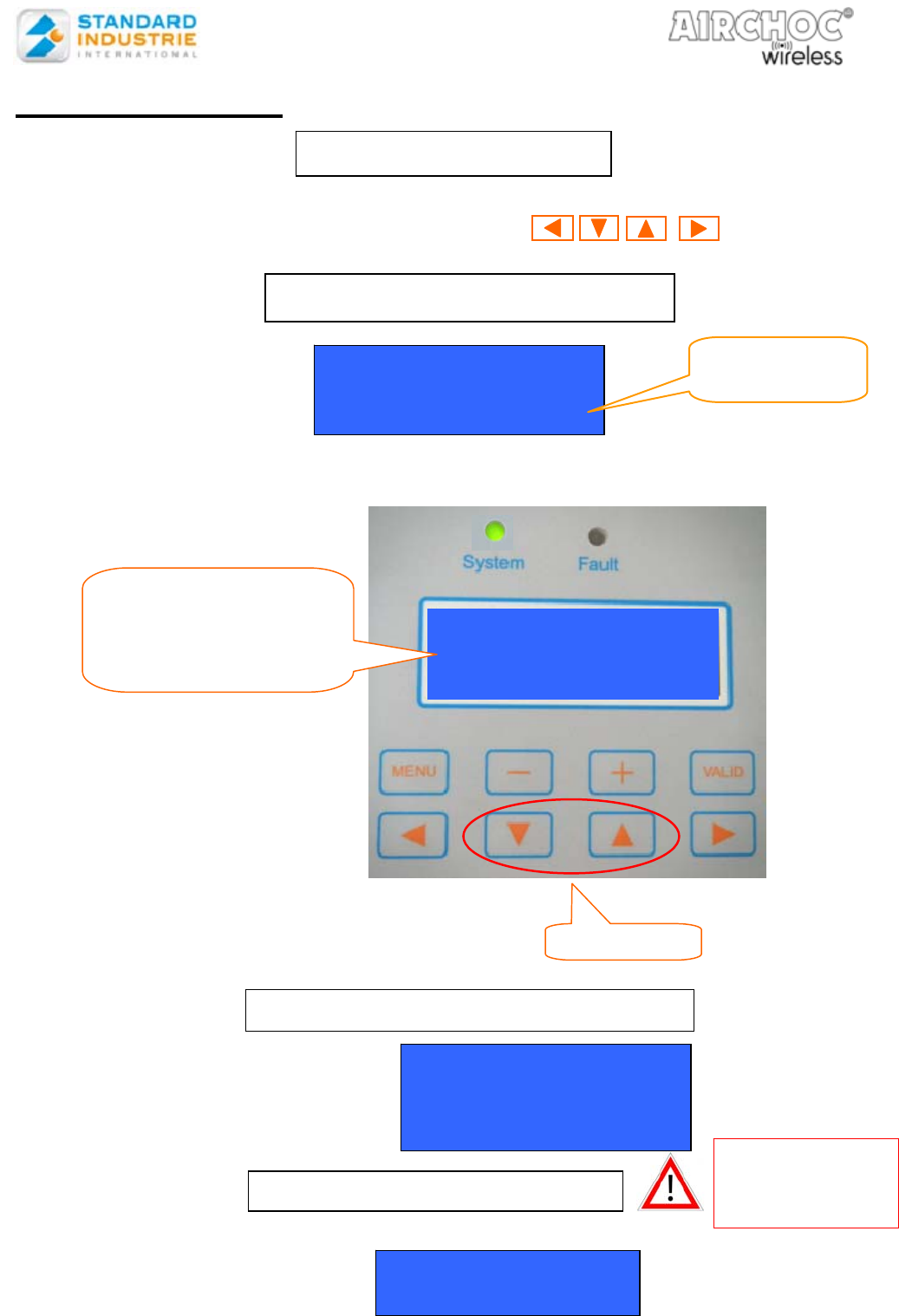
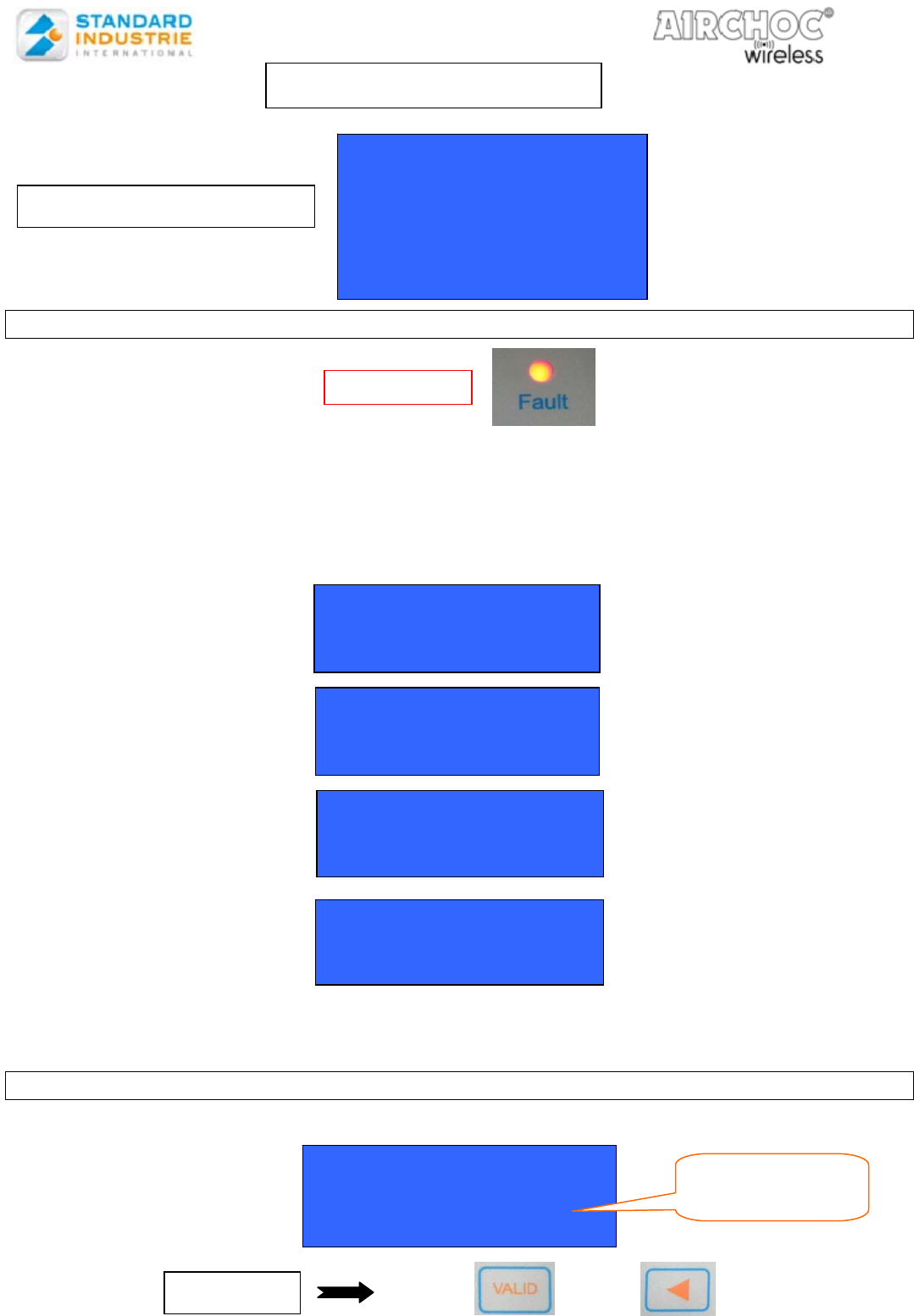
5- CONTROL PANEL START-UP
6- MAIN MENU
It has 10 menus accessible using the ▼ / ▲ keys.
Functions are accessed using the VALID key.
Access to all menus requires an access code, except for selecting the display, language, and
communications test.
Generally:
- the keys ▼ ▲ are used to select a line
- the keys ◄ ► are used to select a field
- the keys + – are used to modify a field
- the
VALID key is used to validate data and save
- the
MENU key is used to enter the menu and get out of an action without saving
STANDARD INDUSTRY
Control panel
Airchoc
Soft version: 3.01
Display Control panel power
on LED indicator
Main Menu:
Display
Manu discharge
Erasure
Airchoc prog
Sequence prog
Sup- sequence prog
Code Management
Language Setting
Control USB key
Communication test
An access code must be
entered to access these
menus
Explanation on page 23
EMERGENCY STOP TRIGGERED
O
R
Faults
Emergency Stop
Unlock
by turning the button
+
press VALID
Red LED
ACCESS FUNCTION WITHOUT NETWORK CREATION OR TO
DIRECTLY ACCESS THE MAIN MENU
Simultaneously press
MENU and VALID
OR
WAIT WHILE SEEKING RECEIVER UNITS
STANDARD INDUSTRY
Control panel
Airchoc
Receivers searchin
g
STANDARD INDUSTRY
Control panel
Airchoc
Network Creation STANDARD INDUSTRY
Control panel
Airchoc
A
ntenna Fault
Ensure the antenna is
correctly connected or
check for a cable problem
POWER-UP On / Off button Green LED
WIRELESS CONTROL PANEL OPERATION
NOTCOFACW-US.doc 13 December 6th, 2012
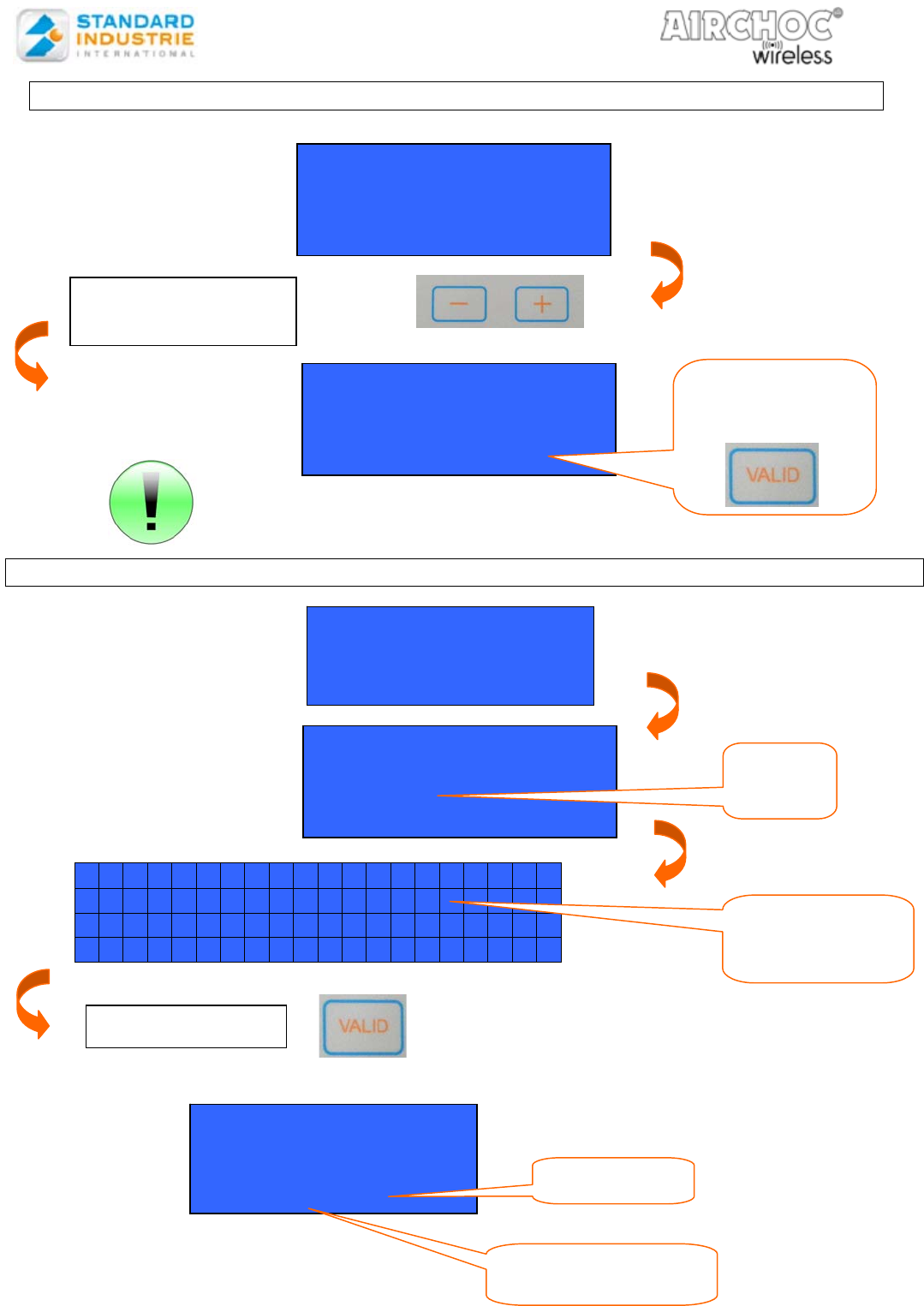
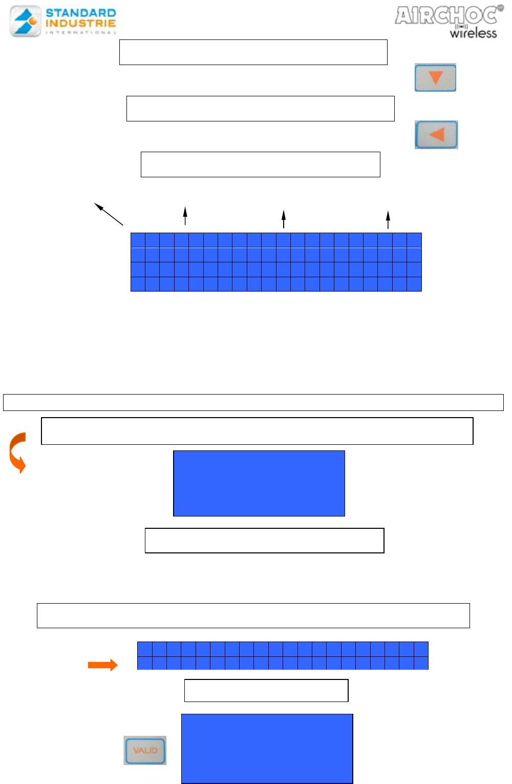
6-1. Menu Operation
Display mode provides for viewing Airchoc program, sequence, and super sequence lines, as well
as the counters and faults using the keys.
The manual firing menu provides for manually triggering an Airchoc whether it is active or inactive.
This is used to check correct Airchoc operation
PRESS VALID AFTER MAKING YOUR
Manu Discharge
Airchoc 01 XXXX
Press VALID
Ensure there is
no danger
before firing
Manual discharge AC
In Progress
Manu discharge menu
Code Entry : 0000
Enter Your
A
ccess Code
6-11. MENU - DISPLAY
6-12. MENU – MANU DISCHARGE
No. Name T1 Config
01 XXXX 0.5s Active
Select an Airchoc that you
previously registered in
the Airchoc prog menu
(see page 17)
Scroll keys
PRESS VALID AGAIN TO FIRE
NOTCOFACW-US.doc 14 December 6th, 2012
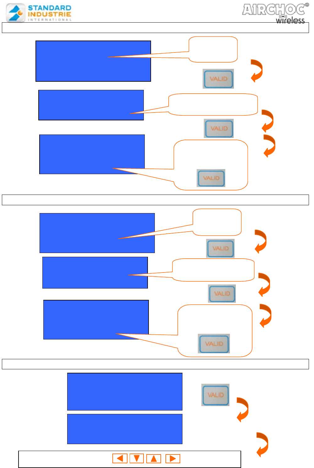
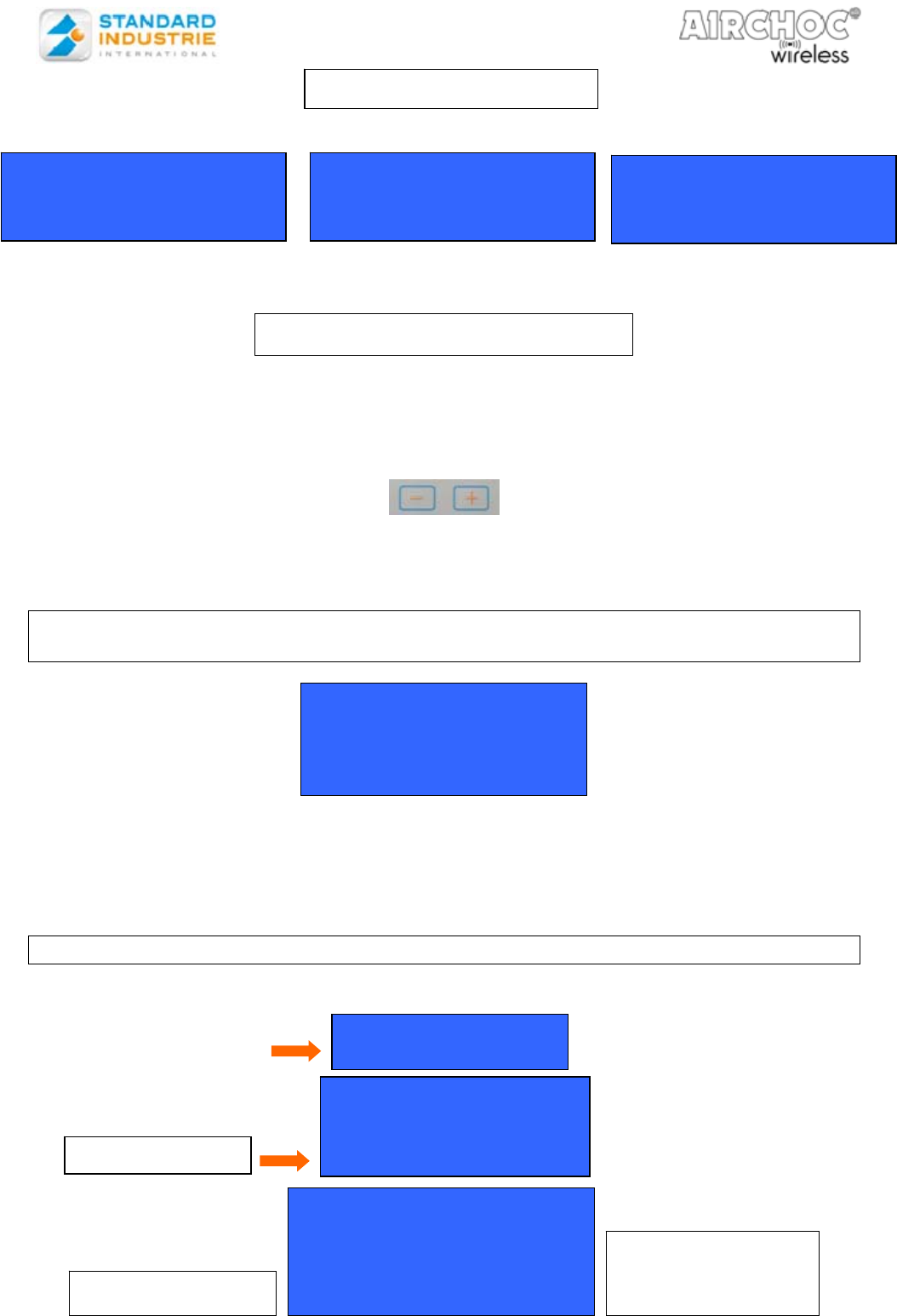
6-13a FAULT PRESENCE
Display fault type:
: Transmission error
: Receptor batt. 25%
: Solenoid valve cut
: Airchoc Maintenance
Only the 4 faults in bold will be saved:
Each fault displayed will be dependent on an Airchoc and may be acknowledged one by one.
6-13b FAULT DELETION
Select the fault type using the ▼ / ▲ keys.
ERASURE choice :
Faults
Airchoc
Sequence
Super - Sequences
Reset by default
Display sub-menus
Red LED
Receptor batt. < 25%
Nr01 XXXX Batt. ok
Transmission error
Nr01 XXXX 0 Fault
Solenoid valve cut
Nr01 XXXX coil ok
Airchoc Maintenance
Nr01 XXXX maint. ok
Transmission error
Nr01 XXXX 0 Fault
Nr02 XXXX Nb: 01
DELETE PRESS then
Select the line to
delete
6-13. MENU - ERASURE
NOTCOFACW-US.doc 15 December 6th, 2012
Go to the menu
Only the last 50 faults are visible.
6-13d AIRCHOC DELETION
N b N a m e A d r e s s M a c
0 1 A C 0 1 0 0 6 4
0 2 A C 0 2 0 0 5 3
0 3 A C 0 3 0 0 5 4
ERASURE OF THE
AIRCHOC
Number : 01 ?
Valid Quit
Select Valid
◄ ke
y
+
V
ALID
Quit flashes
PRESS
ERASURE choice :
Faults
Airchoc
Sequence
Select
the line
Erase menu
Code Entry : XXXX
Select the
Airchoc to be
deleted
Faults :
Transmission error
Receptor batt. 25%
Solenoid Valve cut
Delete all faults
Valid Quit
Select the option
with ◄ ►
+
SIMULTANEOUSLY
PRESS FOR 3S
6-13c GENERAL FAULT DELETION
ON
NOTCOFACW-US.doc 16 December 6th, 2012
6-13e SEQUENCE DELETION
6-13f SUPER SEQUENCE DELETION
6-13g FACTORY RESET
ERASURE choice :
Sequence
Super Sequence
Factor
y
Reset
Factory
Reset
Simultaneously press to validate
Number Config
01 Active
02 Inactive
ERASURE choice :
Sequence
Super Sequence
Factor
y
Reset
Select the
line
Select the Super
se
q
uence to delete
ERASURE OF THE
SUPER-SEQUENCE
Number: 01 ?
V
alid Quit
Select the option
with ◄ ►
+
Number Config
01 Active
02 Inactive
ERASURE choice :
Sequence
Super Sequence
Factory Reset
Select the
line
Select the Sequence
to delete
ERASURE OF THE
SEQUENCE
Number: 02 ?
V
alid Quit
Select the option
with ◄ ►
+
NOTCOFACW-US.doc 17 December 6th, 2012
From the main menu, press the key until the Airchoc prog line flashes. Then press
the VALID key in order to enter the menu. The Airchoc, receiver unit MAC address, and
configuration lines are displayed.
Key to use : to increase
Key to use : to go to the next character
Press and hold : to fast forward
Main Menu:
Prog Airchoc
Prog Sequence
Prog Supsequence
Nb Name AdressMAC
01 AC01 0030
02 AC02 0035
4 alphanumeric
characters
possible
Physical Airchoc number
4 characters
address
MAC address
6-14. MENU -
A
IRCHOC PROGRAMMING
6-14a Receiver Unit MAC Address
NOTCOFACW-US.doc 18 December 6th, 2012
Go to the last line saved, press and hold the key
Go to the Airchoc to be deleted, press and hold the key
After selecting the Airchoc using the ▼ and ▲ keys, you may access the settings using
the ◄ ► keys.
3 fields are accessible for each Airchoc:
The T1 field is 0.5 s by default.
The Config field is used to deactivate an Airchoc. If an Airchoc is in inactive mode
and present in a sequence, the canon may not be triggered. It is inactive by default.
6-14b AIRCHOC REGISTRATION
After configuring the Airchocs, a communication test may be performed in order to ensure
correct communications between the Control panel and the receiver units.
ADD AN AIRCHOC
DELETE AN AIRCHOC
CONFIGURING THE AIRCHOC
AIRCHOC COMMUNICATION TEST
Pressing MENU + VALID will register the Airchoc
AIRCHOC
Record
validation
No: Menu Yes: Valid
In the same menu, go to the Airchoc line to be tested
Communication test :
Airchoc AC01
No Menu Yes Valid
PRESS VALID
AIRCHOC Name T1
(
Pulse time
)
Configuration
(active / inactive)
Step no.
Press the
key to accept
N b N a m e T 1 C o n f i g
0 1 A C 0 1 0 . 5 s A c t i v e >
0 2 A C 0 2 0 . 5 s A c t i v e
0 3 A C 0 3 0 . 5 s I n a c t i v
N b N a m e T 1 C o n f i g
0 1 A C 0 1 0 . 5 s
A
c t i v e >
NOTCOFACW-US.doc 19 December 6th, 2012
Display Various Counters
- Client counter (CustCount): number of Airchoc firings (may be reset).
The counter increases every time it communicates with the receiver unit.
Simultaneously press VALID + ◄
- Counter (MaxClient) is an adjustable maintenance threshold. When the CptClient exceeds the
MaxClient value a maintenance fault will be triggered. By default it is set to 0050000. The value
may be increased or decreased from 50000 by 1000s with the keys
- STANDARD INDUSTRIE counter (Sindcount): The counter increases every time it
communicates with the receiver unit. This counter may not be initialized. It is used for monitoring
by our technical services.
5-14d RECEPTION LEVEL BETWEEN THE CONTROL PANEL ANTENNA MODULE
AND THE RECEIVER UNIT
The Airchoc Signal Level is a means of checking reception quality between the Control panel
antenna module and the receiver units. This value may range from 0, meaning no signal, to 28,
meaning perfect signal quality. This value must be greater than 5 for the facility to operate
correctly.
A value less than 5 may cause communication faults.
6-14e NETWORK MONITORING
The presence or absence of the various components composing the network may be
checked. Go to
COUNTER RESET
Nb Name Signal Level
01 AC01 20
02 AC02
03 AC03
Code required for
AdressMac State
0056 This A
0063 Absent A
0045 This R
0002 This T
A= Airchoc
R= Router
T= Remote Control
Nb Name CustCount
01 AC01 0000000
02 AC02 0000000
Nb Name Max Client
01 AC01 0050000
02 AC02 0000000
Nb Name Sindcount
01 AC01 0000000
02 AC02 0000000
Main Menu :
Dis
p
la
y
Display choice :
Super Sequence
Faults
General Network
Last tab
6-14c COUNTERS
NOTCOFACW-US.doc 20 December 6th, 2012
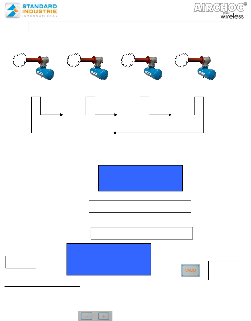
Example of sequence programming
Programming a sequence
From the main menu, press the ▼ key until the Prog Sequence line flashes. Then press VALID to begin
programming.
Always enter the access code to gain access to sequence configuration.
Go to the last sequence and press and hold ▼
Servo-control Assignment
Move to the sequence of your choice and press the VALID key to select it.
Access the settings using the ▼ ▲ keys.
3 fields are accessible for each sequence:
Change fields using the keys
The Config field activates or deactivates the sequence. If a sequence is deactivated, no
servo-control is assigned to that sequence. If a sequence is in inactive mode and it is
present in a super sequence, it may not be triggered.
The Servo-control is used to assign the corresponding servo-control to a dry contact
On/Off controller input. 16 servo-controls are possible.(See page 7)
The state field provides for defining the type of servo-control assigned to the sequence: 5
statuses are possible: NO Reset, NC Reset, NO Pause, NC Pause, and Inactive. “Reset”
reinitializes the cycle, “Pause” stops the cycle, “NO” and “NC” define the status type.
“Inactive” deactivates the servo-control input.
Sequence Config
01 Active
02 Inactive
ADD A SEQUENCE
CONFIGURE A SEQUENCE
Sequence Nr: 01
Config: Active
Servo-control : 01
State: NO RESET
Step 1
Press To go to
step 2
T1
AIRCHOC AC01
Step no.1
T2 Step no. 1=15s
T1
AIRCHOC AC02
Step no. 2
T2 Step no. 2=30s
T1
AIRCHOC AC03
Step no. 3
T2 Step no. 3=15s
T1
AIRCHOC AC04
Step no. 4
T3 for Sequence 1 =1min.
6-15. MENU
–
SE
Q
UENCE PROGRAMMING
NOTCOFACW-US.doc 21 December 6th, 2012
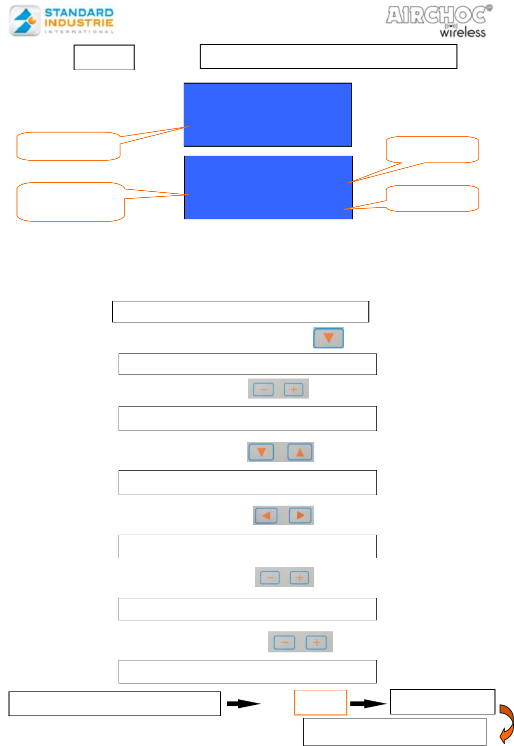
Sequences are programmed line by line. Each line corresponds to a step in the
sequence. For each step, an Airchoc – its address – must be assigned.
Moreover, between 2 steps, a time (T2) must be indicated, except for the last sequence
step which will have a time (T3) before the cycle repeats.
Press and hold
Key
Key
Key
Key
Press and hold
CREATING THE PROGRAM
Step 2
Sq01 Airchoc T2m:s
001 AC01 000 :15
002 AC02
T3
(
h:m:s
)
= 00 : 15 : 00
Sq01 Airchoc T2m:s
001 AC01 000 :15
002 AC02
T3
(
h:m:s
)
= 00 : 15 : 00
Step no. in the
Sequence
Sequence No. Time T2
Time T3
SELECT AN AIRCHOC
CHANGE STEP
GO TO SETTINGS
CHANGE TIMES
INCREASE QUICKLY
LEAVE THE SEQUENCE
Save the program
VALIDATE THE PROGRAM VALID Key
MENU
2x
INSERT A STEP
NOTCOFACW-US.doc 22 December 6th, 2012
Program creation:
Super sequences are programmed line by line. Each line corresponds to a step in the super sequence.
For each step, a sequence must be assigned by number. Moreover, between 2 steps, there is a time (T3)
corresponding to the T3 time programmed in the sequence. Lastly, the last sequence step has a time (T4)
before the cycle repeats.
Example of super sequence programming:
6-16a SUPER SEQUENCE CONFIGURATION
Servo-control and status settings are the same as for the Sequence menu.
6-16b SUPER SEQUENCE PROGRAMMING
Use the same keys as for a sequence
After programming the various steps, you must set the T4 time. To do
so move to the last line using the key and then use the key .
Move to the T4 time and change the values using the keys /
Step 1 SupSequence Config
01
02
Select the Super-sequence
to configure
+ -
VALIDATE THE PROGRAM VALID Key
MENU
2x
SupSeq01 Sq
001 01 00:01:00
002
T4
(
h:m:s
)
= 00:05:30
Super-sequence no.
Sequence no.
Time T3
Super -Sequence Nr 01
Config: Inactive
Servo-control : 01
State : Reset NO
PRESS VALID
SEQUENCE no.1
step no.1
SEQUENCE no. 3
step no. 3
SEQUENCE no. 2
step no. 2
T3 sequence no.1 T3 sequence no. 2
T4 for super-sequence 1
SupSeq01 Sq
002 02 00:01:00
T4 (h: m: s) = 00:05:30
6-16. MENU - SUPER SEQUENCE PROGRAMMING
Save the program
NOTCOFACW-US.doc 23 December 6th, 2012
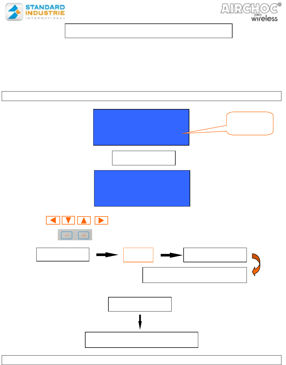
This menu is used to create, modify, or initialize access codes used to enter the various
menus.
To access this code management menu, you must enter code 2 (by default this code is
0000).
We suggest you change this code the first time you use the Control panel.
6-17a CODE CREATION / MODIFICATION
Use the keys to access the various codes or characters.
Use the keys to increase or decrease the digits.
OR
6-17b CODE LEVELS
Code 1: this code provides access to manual Airchoc firing, the view menu, and
language selection.
Code 2: this code provides access to all menus and programming, allows resetting
counters, except for the Standard Industrie counter. Fault deletion.
Code 3: this code is exclusively reserved for Standard Industrie access.
Using this code a Standard Industrie technician has access to all Control
panel functions and may reset the Standard Industrie counter.
Code Management
Create - Modify
Initialize
VALID Key
Config Password
Code 1 : 0000
Code 2 : 0000
Code 3 : xxxx
MENU Key
Quit without saving
PRESS VALID key MENU
Save the code
Menu
selection
6-17. MENU-ACCESS CODE MANAGEMENT
NOTCOFACW-US.doc 24 December 6th, 2012
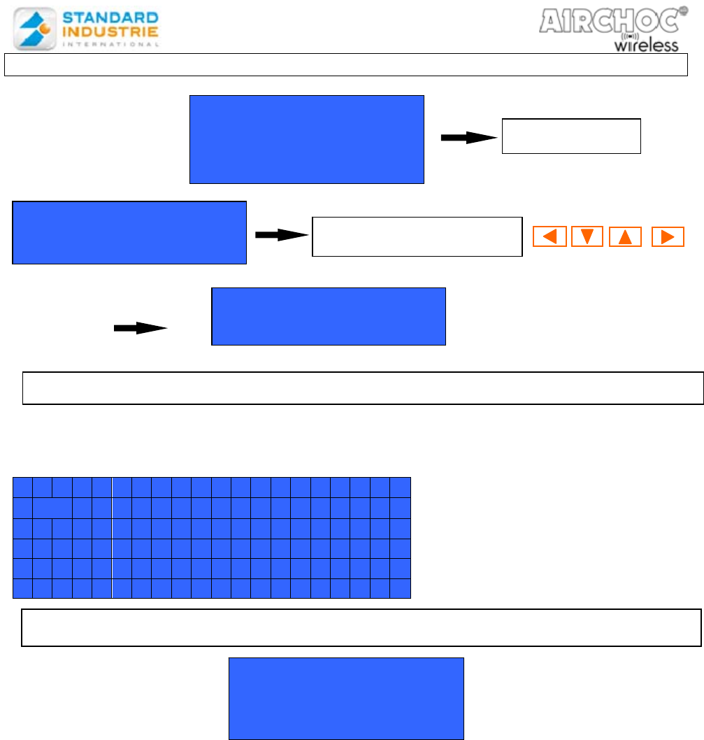
6-17c CODE TABLE INITIALIZATION
From the main menu press the ▼ key until the Language setting line flashes. Then
press VALID to save the language.
L a n g u a g e s e t t i n g
F r a n c a i s
E n g l i s h
E s p a g n o l
D e u t s c h
I t a l i a n o
This menu is used to upload a new program or download a program from the
Control panel with our “AIRCHOC TRANSFER SYSTEM” software.
Menu USB Key
Enter code: XXXX
Code Management
Create - Modify
Initialize
VALID Key
Reinitialize
Completing the Code table
Record
No: Menu Yes: Valid
Simultaneously press
6-18 Menu - Language Setting
6-19 Menu – Control USB Key
NOTCOFACW-US.doc 25 December 6th, 2012
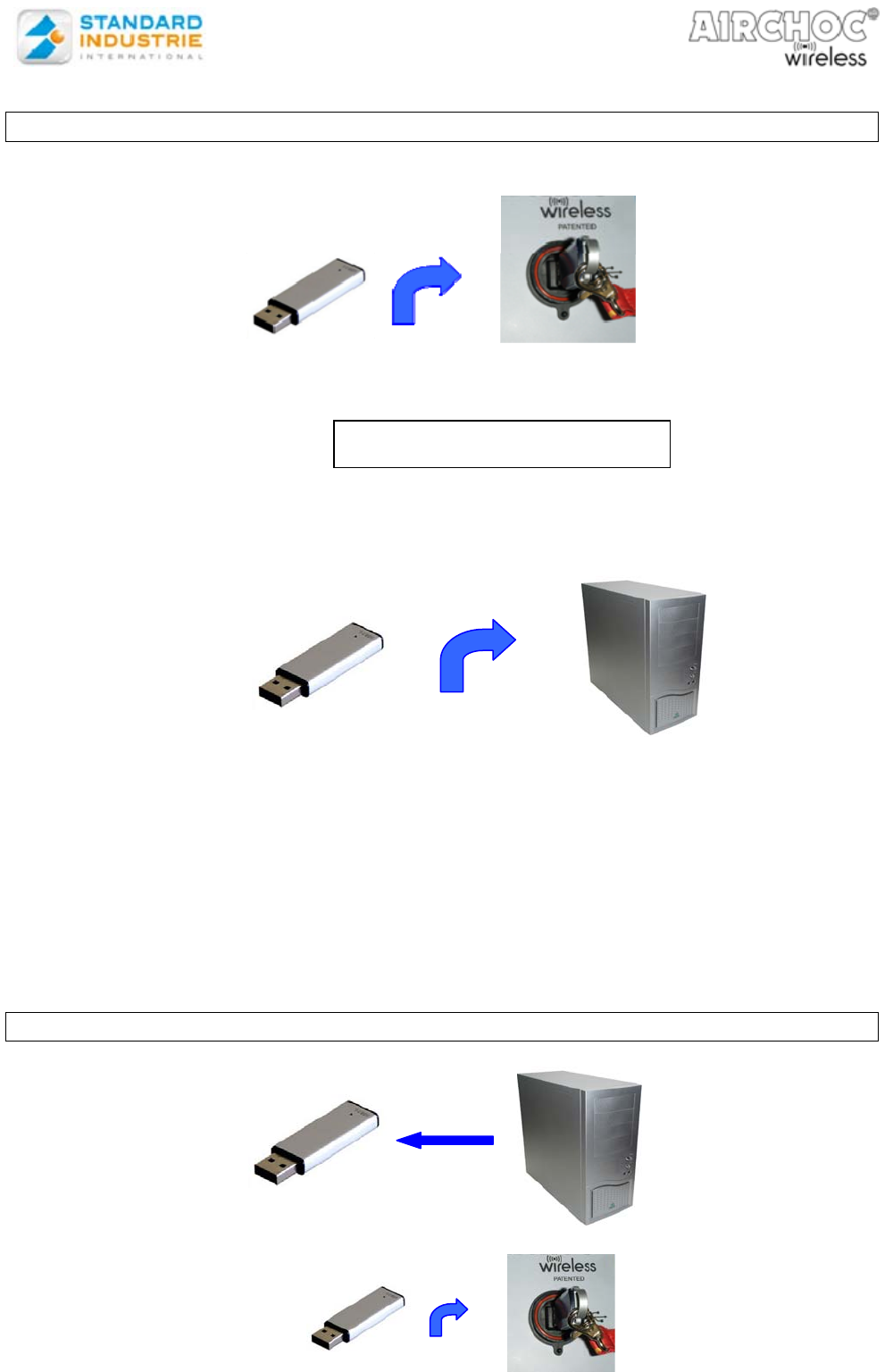
6-20a SAVE PROGRAM
-Insert the key into the Control panel which has been turned on.
- Go to the menu USB Key on the Control panel
- When you return to the main menu, remove the key.
- Insert the key in the PC where the “AIRCHOC TRANSFER SYSTEM” software
is installed.
- Run the “Airchoc Transfer System” software
- Select “Load”
- The “Select” to find the location on the USB key
(for example “removable disk (D:)”).
- Then validate
- The 3 boxes Airchoc – Sequences – Super Sequences are displayed.
The Control panel settings are present in these 3 tables.
Here, you can modify or add an Airchoc for example. Each time you press “modify,” “add,”
or “delete” it is saved to the key!
6-20b UPLOADING PROGRAMS TO THE CONTROL PANEL
HANDLING
Save
NOTCOFACW-US.doc 26 December 6th, 2012
- Go to the menu USB Key on the Control panel
- Select “Upload”
All the changes made are now in the Control panel.
6-20c UPDATING THE CONTROL PANEL VERSION
Using this menu, you may check the connection between the Control panel and the
receiver units at any time.
The same functions as when starting-up the Control panel are available.
Main Menu:
Language Setting
Control USB Key
Communication Test
Select the menu
VALID Key
TURN OFF THE
CONTROL PANEL
TURN THE CONTROL
PANEL BACK ON
STANDARD INDUSTRY
Control panel
Airchoc
V
ersion soft : 3 :01
2 LEDs ON
Updating the software
does not erase existing
program
Control USB Key
Code Entry : XXXX
6.21- COMMUNICATION TEST
NOTCOFACW-US.doc 27 December 6th, 2012
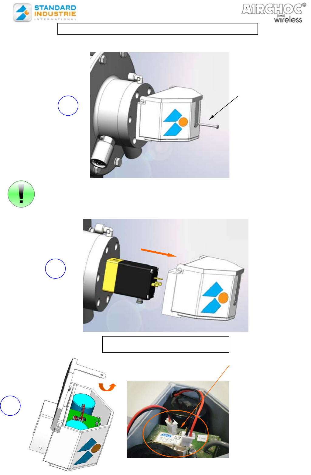
7- CHANGING RECEIVER UNIT BATTERIES
Use a flat screwdriver with a max. blade thickness of 0.5
If the Airchoc is hard to reach, remove the receiver unit from
the solenoid valve
1
Unscrewing the
M3x35 screw
Disconnect the 2 connectors
3
2
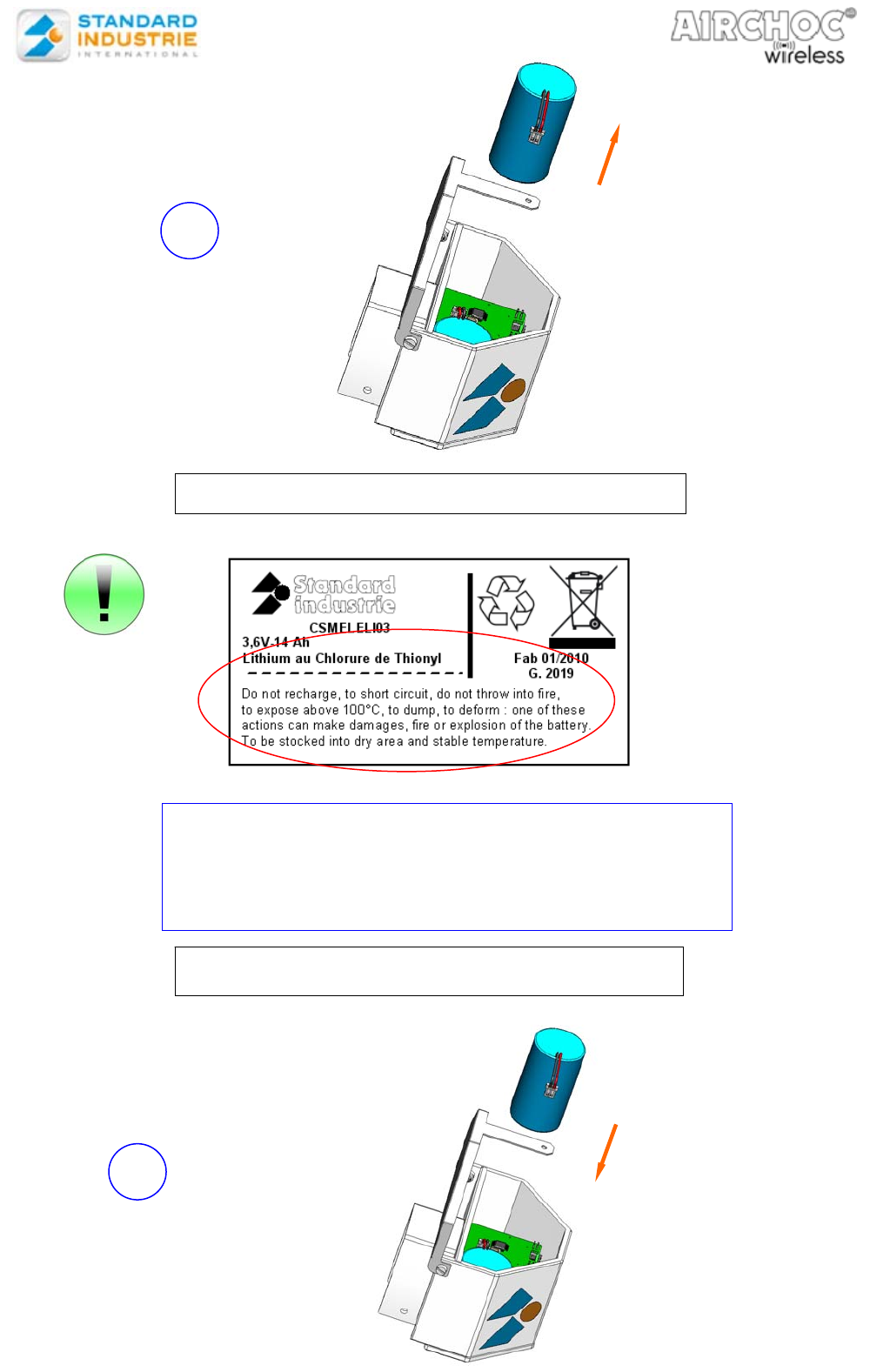
REMOVE THE BATTERIES
NOTCOFACW-US.doc 28 December 6th, 2012
BATTERY INSTRUCTIONS, REMINDER
Do not recharge, to short circuit, do not throw into fire, to
expose above 100°C, to dump, to deform : one of these
actions make damages, fire or explosion of the battery. To
be stocked into dry area and stable temperature.
INSTALLING NEW BATTERIES
4
5
NOTCOFACW-US.doc 29 December 6th, 2012
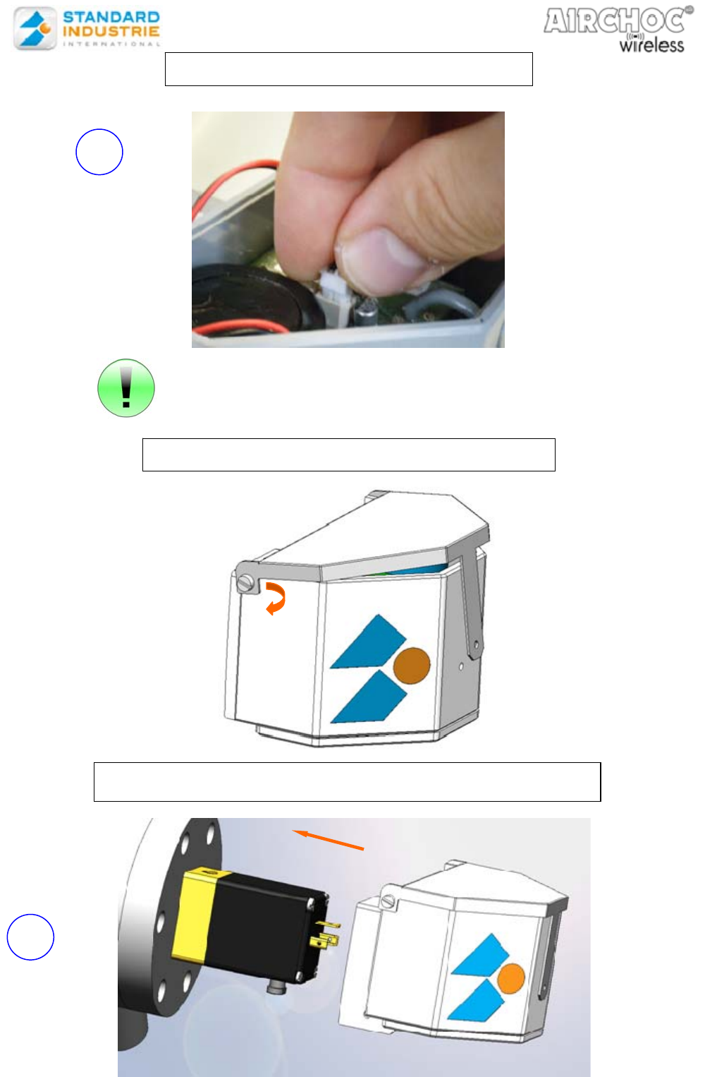
CONNECTING THE CONNECTORS
CLOSE THE COVER
Press the connectors until you hear a click
6
7
ATTACH THE HOUSING TO THE SOLENOID VALVE
NOTCOFACW-US.doc 30 December 6th, 2012
The housing must abut the base Ensure than the manual solenoid valve
control is correctly positioned in
relation to the oblong hole
8
ATTACH THE HOUSING TO THE SOLENOID VALVE
Press down on the
cover until you are
in front of the screw
hole