Standard Industrie COFROUTCA ROUTER FOR AIRCHOC WIRELESS APPLICATION User Manual NOTCOFROUT US G1
Standard Industrie ROUTER FOR AIRCHOC WIRELESS APPLICATION NOTCOFROUT US G1
User Manual
NOTCOFROUT-US.doc 1 December 6th, 2012
USER
MANUAL
Revision Level: G1
NOTCOFROUT-US Date: December 6th, 2012
Produced on: December 6th, 2012
By: DESIGN OFFICE
Checked on:
By: BOISLEUX.M
Signature:
HEAD OFFICE- Standard Industrie : 139-141 rue du Luxembourg-BP50207 59054
ROUBAIX CEDEX 1- FRANCE
+33 (0)3 20 28 32 32 / @ : info@standard-industrie.com

NOTCOFROUT-US.doc 2 December 6th, 2012
CONTENTS
1 Principle of Airchoc Wireless page 3
2 Router presentation page 4
2-2 General characteristics page 4
2-21 Electrical characteristics page 4
2-22 Explanation of the symbol on the label page 4
2-23 Environmental characteristics: page 4
2-24 Additional exterior characteristics page 4
3 Network with router page 4
3-1 Principle page 5
4 General information Page 6
NOTCOFROUT-US.doc 3 December 6th, 2012
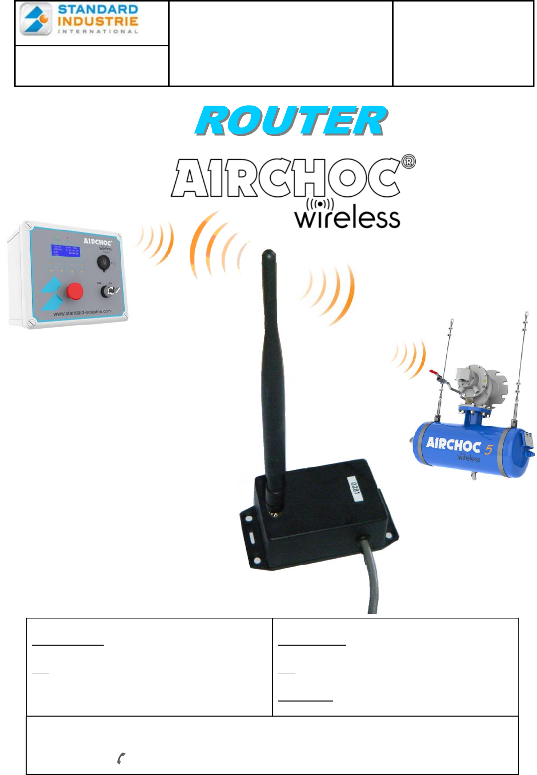
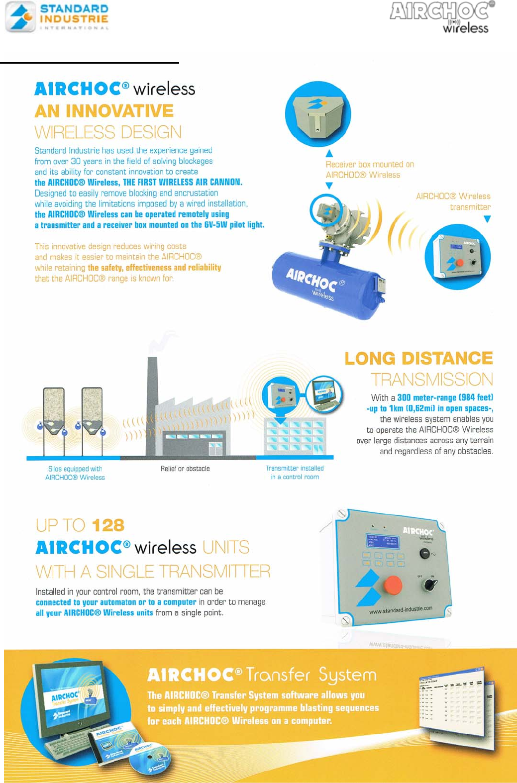
1- Principle of Airchoc Wireless
NOTCOFROUT-US.doc 4 December 6th, 2012
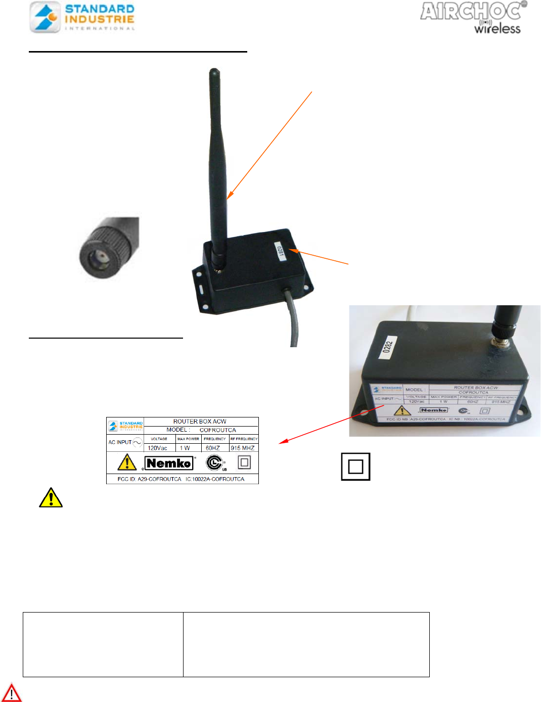
2- ROUTER PRESENTATION
2-2. General Characteristics
2-21. Electrical Characteristics
- Power supply : 120V ac - 60Hz
- Max power : 1W
2-22. Explanation of the symbol on the label :
After power has been removed and the overcurrent condition eliminated, the circuit is restored to
normal operating condition
This device complies with Part 15 of the FCC Rules. Operation is subject to the following two
conditions: (1) this device may not cause harmful interference, and (2) this device must accept
any interference received, including interference that may cause undesired operation.
2-23. Environmental characteristics:
Material : Flame Retardant ABS (UL94-V0)
- Service temperature:
- Humidity :
- Max altitude
- Pollution degree
Minimum: -20°C
Maximum: +70°C
no more than 80%
e.g up to 2000 m
2
Attention : it is forbidden to clean the control panel to the high-pressure water.
The protection is impaired if equipment is used in a manner not specified by the
manufacturer.
- Electric cable used for connecting have to be in accordance with the standard IEC 60320-1, 60227
2-24. Additional Exterior Characteristics
This router includes
-RF transmission module - 915 MHz as per IEEE 802.15.4-2003/2006 standard
Number of address of the router which
will be visualized in the network
There is no risk of power to hit
the metal part of the antenna
out
p
ut if the router is
p
owered.
This router is Class II
The router is protected by a resettable fuse 0,16A and no dismantling of the box is called.
Wireless external antenna
Standard Industrie reference : COFANTENNA
Characteristics
Frequency [MHz] : 868-928
Gain [dBi] : 3.0
Impedance [Nom] : 50Ω
VSWR : ≤2.0
Polarization : Vertical
Electrical length : ¼, dipole
Radiation : Omni
NOTCOFROUT-US.doc 5 December 6th, 2012
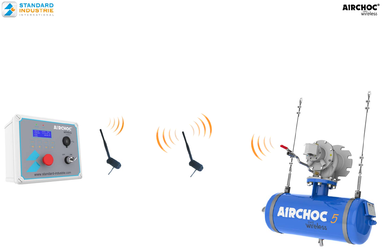
3) NETWORK WITH ROUTER FOR SYSTEME WIRELESS
3-1) Principle
In the case of transmission problems between the control panel and the receivers, routers can be installed.
While positioning the routers on high points, and provide a power supply.
The control panel communicates with the router through the antenna.
The router relays the information to the receiver
Antenna
Control
p
anel
Router
Receiver
Control panel
Power

NOTCOFROUT-US.doc 6 December 6th, 2012
4 – General Information
Changes or modifications not expressly approved by Standard Industrie could void the user's
authority to operate the equipment.
This equipment has been tested and found to comply with the limits for a Class B digital
device, pursuant to part 15 of the FCC Rules. These limits are designed to provide
reasonable protection against harmful interference in a residential installation. This
equipment generates, uses and can radiate radio frequency energy and, if not installed and
used in accordance with the instructions, may cause harmful interference to radio
communications. However, there is no guarantee that interference will not occur in a
particular installation. If this equipment does cause harmful interference to radio or television
reception, which can be determined by turning the equipment off and on, the user is
encouraged to try to correct the interference by one or more of the following measures:
—Reorient or relocate the receiving antenna.
—Increase the separation between the equipment and receiver.
—Connect the equipment into an outlet on a circuit different from that to which the receiver is
connected.
—Consult the dealer or an experienced radio/TV technician for help.
This equipment complies with FCC’s radiation exposure limits set forth for an uncontrolled
environment under the following conditions :
1. This equipment should be installed and operated such that a minimum separation distance
of 20cm is maintained between the radiator (antenna) and user’s/nearby person’s body at
all times.
2. This transmitter must not be co-located or operating in conjunction with any other antenna
or transmitter.