Stanley Security Solutions SDC2K Wireless Electronic Lock User Manual Manual 2
Stanley Security Solutions, Inc. Wireless Electronic Lock Manual 2
UserManual.wiki
>
Stanley Security Solutions
>
SDC2K User Manual
>
Manual 2
Contents
1.
user manual
2.
user manual 2nd part
3.
Manual 1
4.
Manual 2
5.
Manual 3
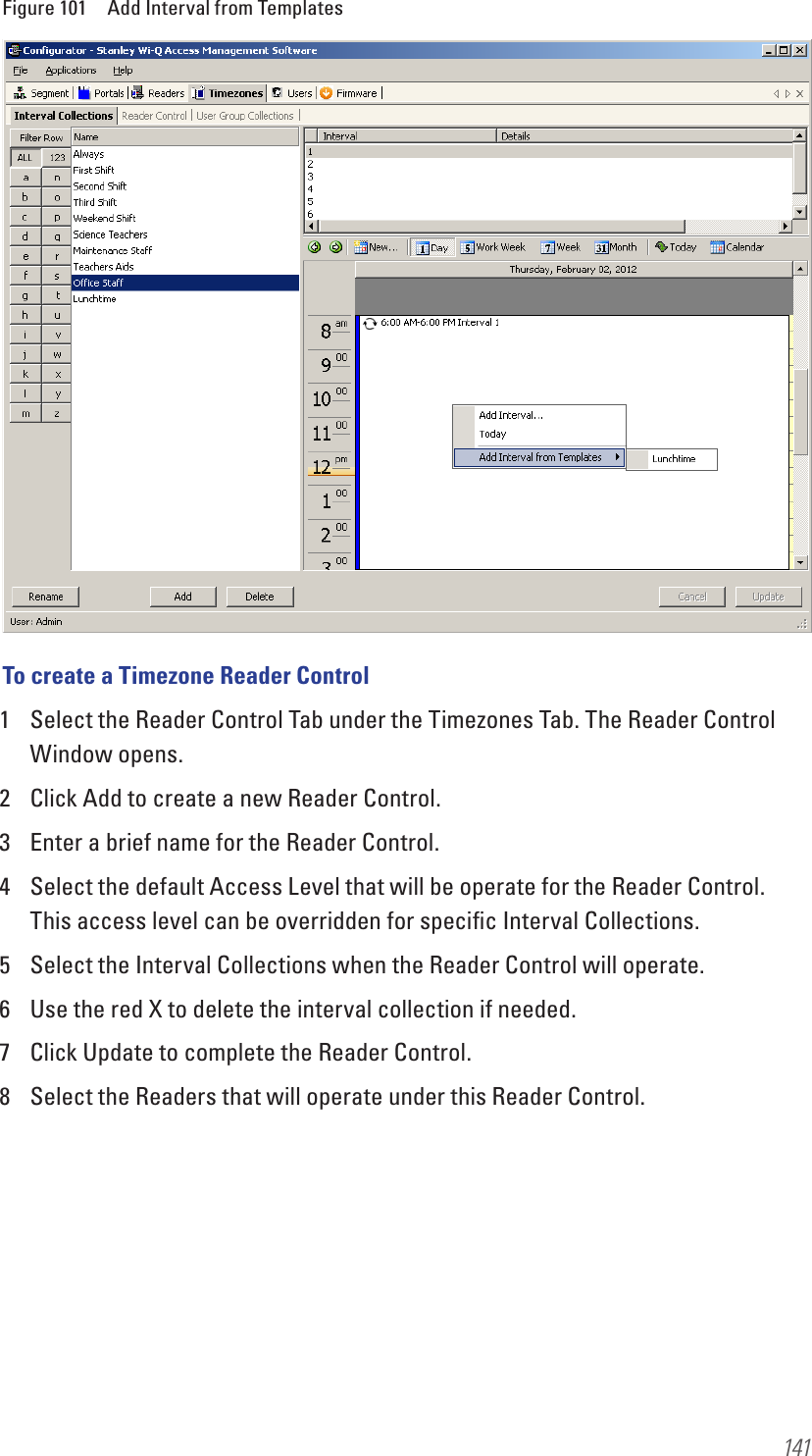
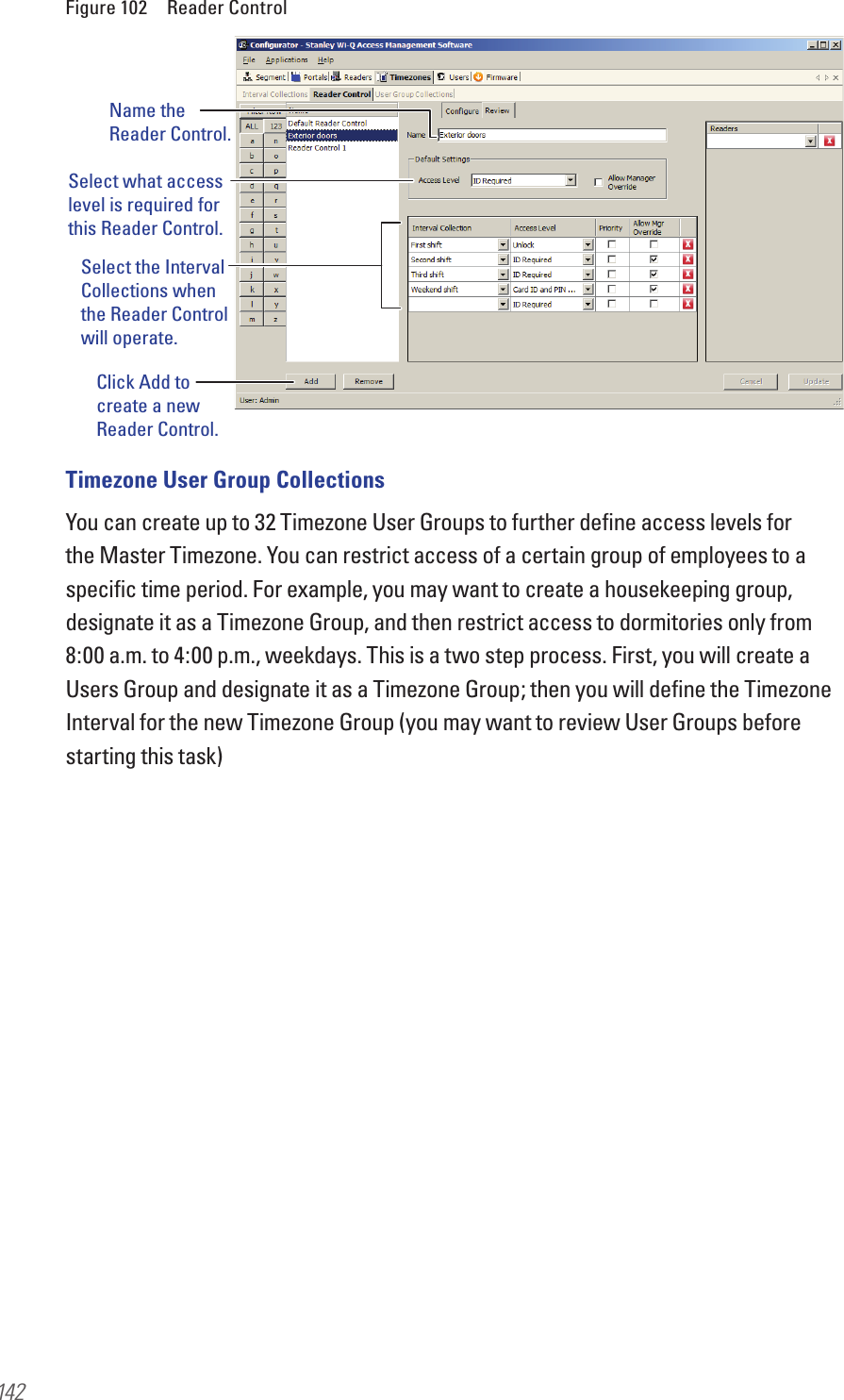
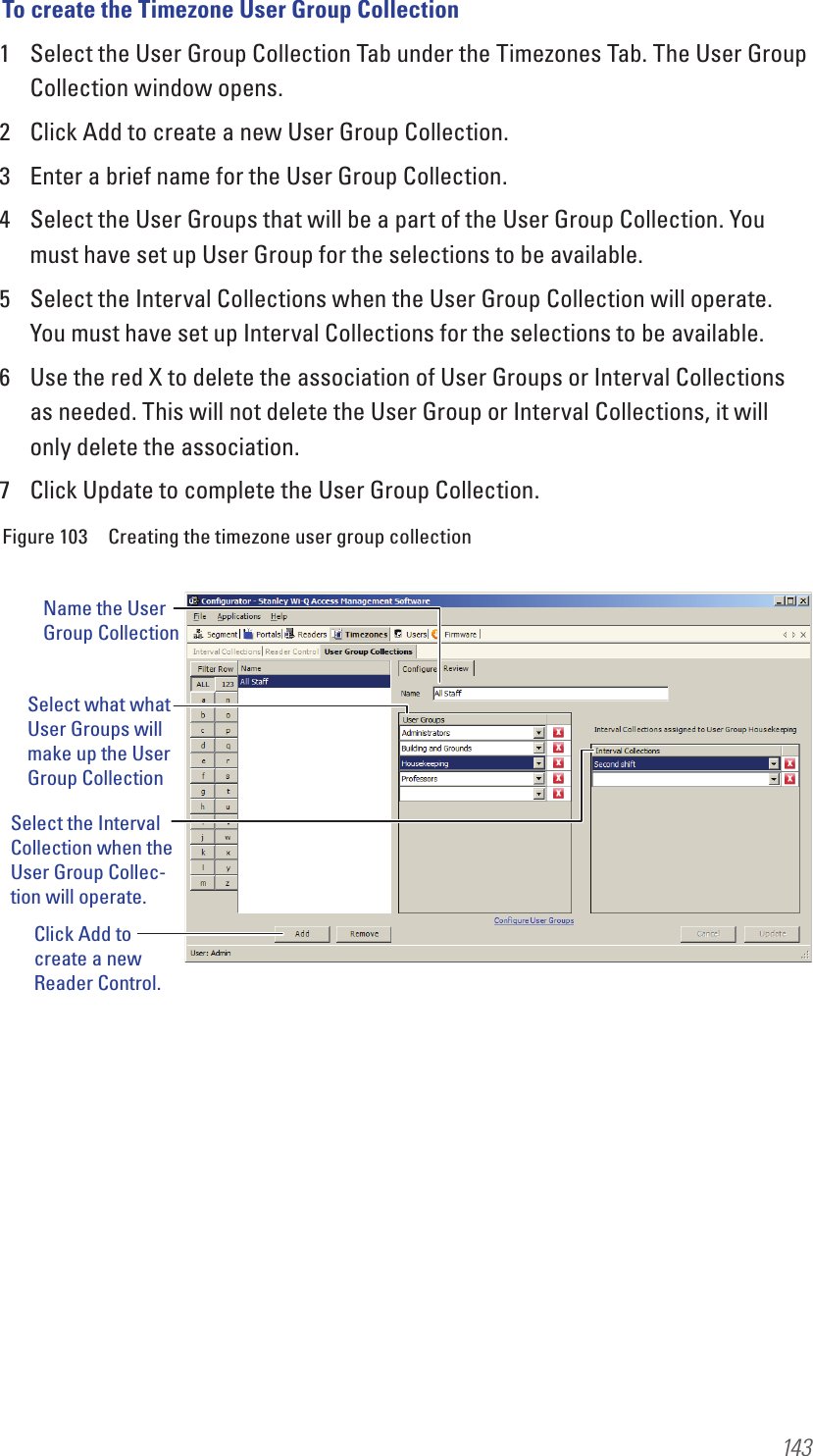
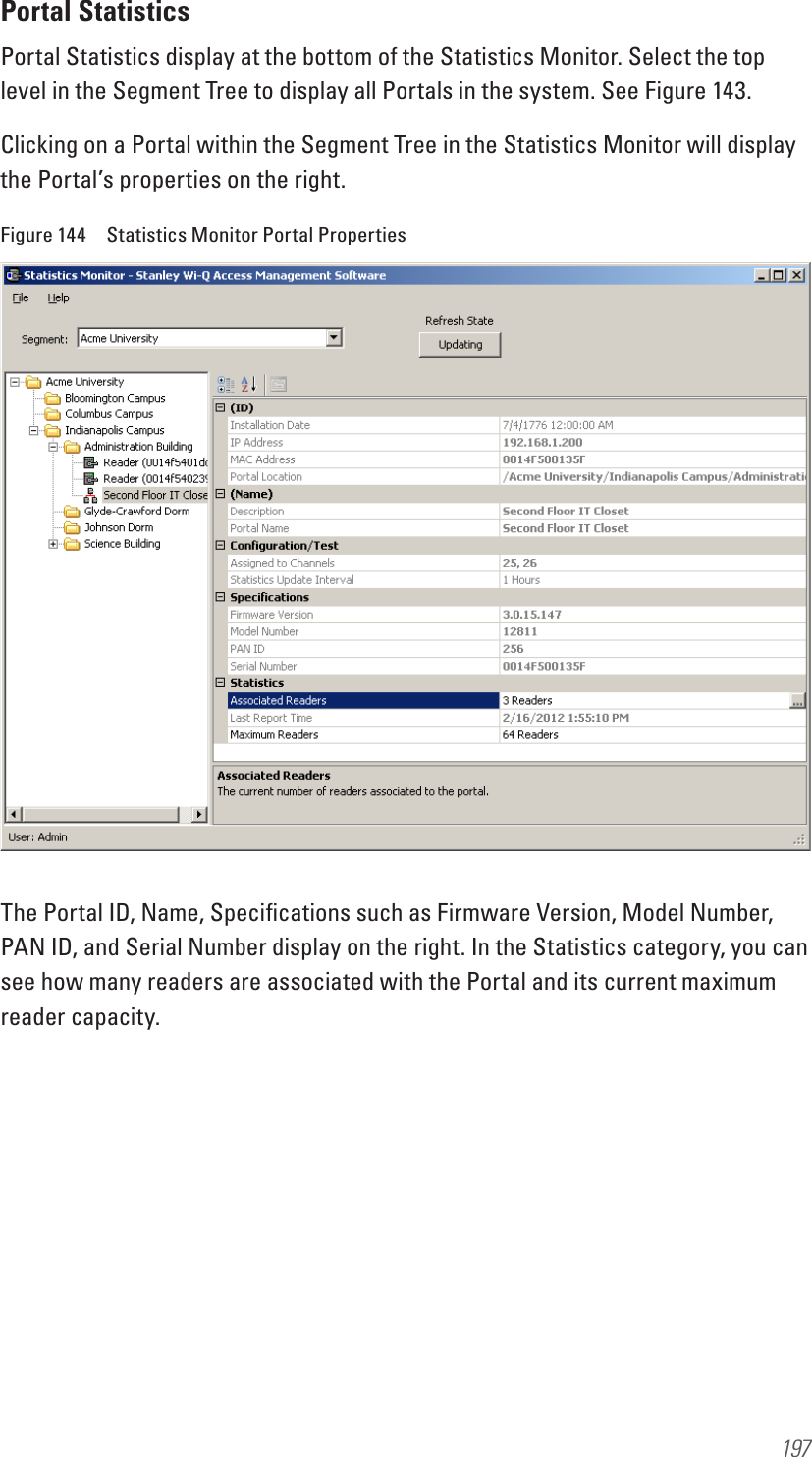
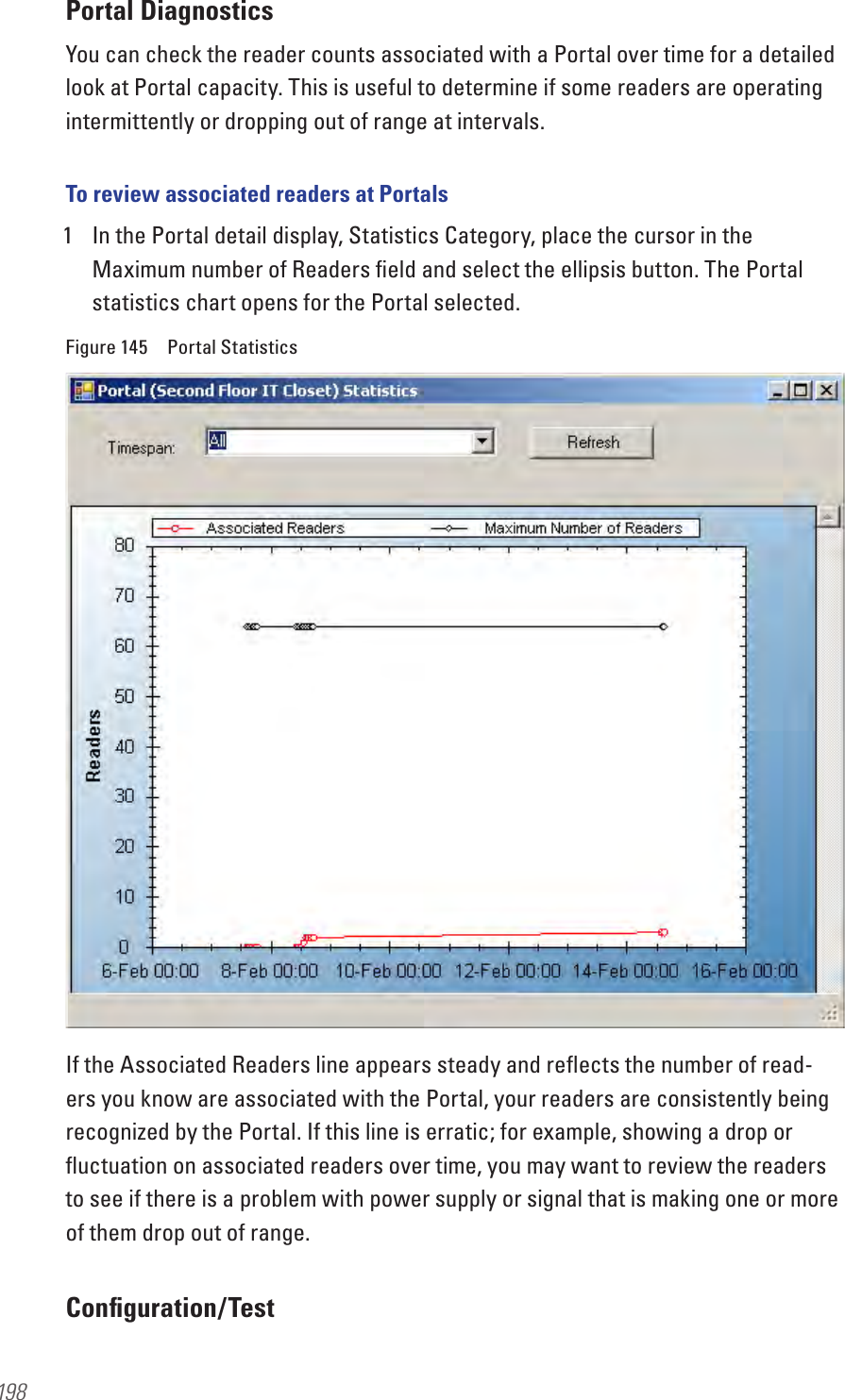
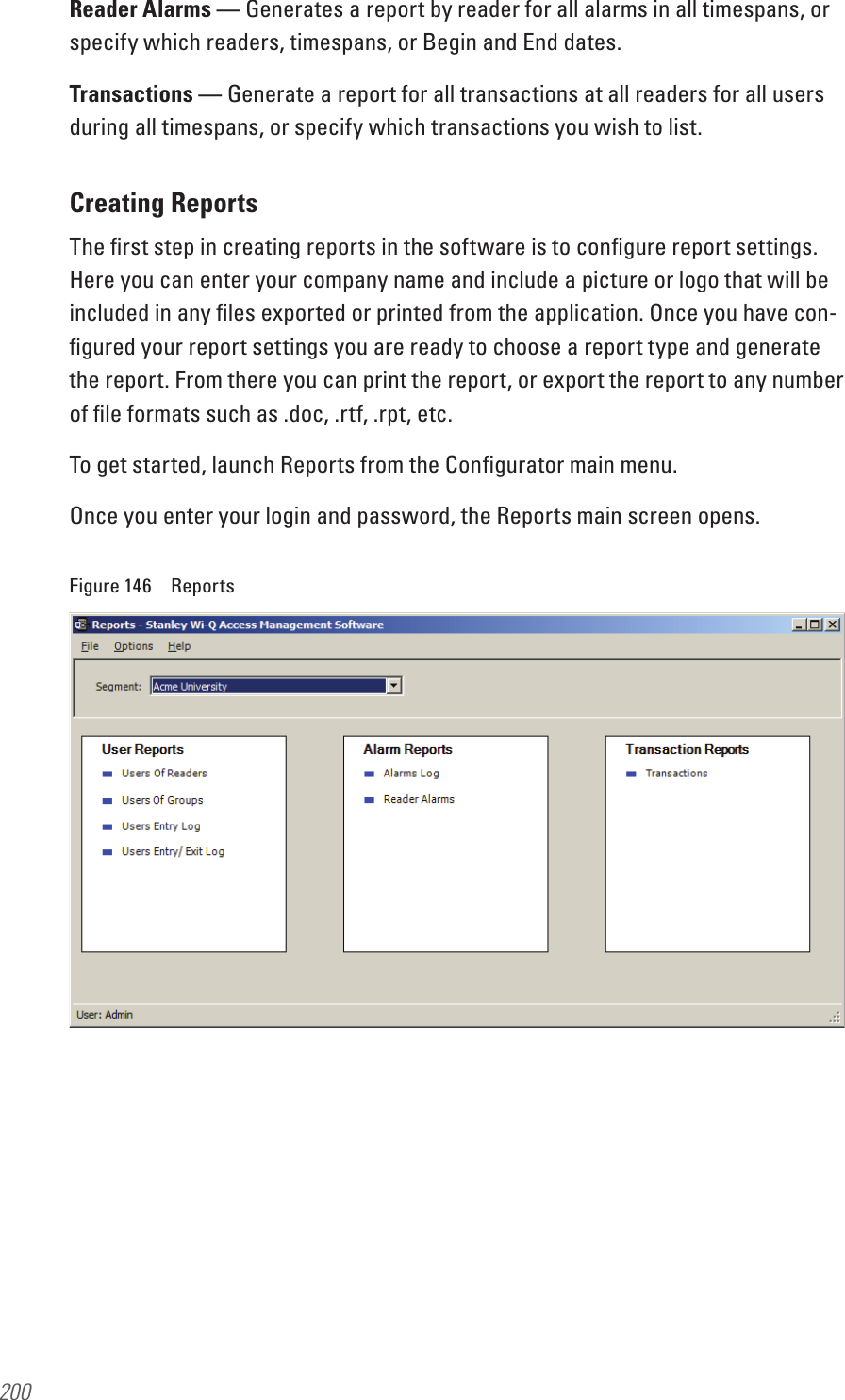
Manual 2
Navigation menu
Upload a User Manual
Namespaces
Wiki Guide
HTML
PDF
Info
Views
User Manual
Discussion / Help
Navigation