Stanley Security Solutions SDC2K Wireless Electronic Lock User Manual Manual 3
Stanley Security Solutions, Inc. Wireless Electronic Lock Manual 3
UserManual.wiki
>
Stanley Security Solutions
>
SDC2K User Manual
>
Manual 3
Contents
1.
user manual
2.
user manual 2nd part
3.
Manual 1
4.
Manual 2
5.
Manual 3
Manual 3
Navigation menu
Upload a User Manual
Namespaces
Wiki Guide
HTML
PDF
Info
Views
User Manual
Discussion / Help
Navigation

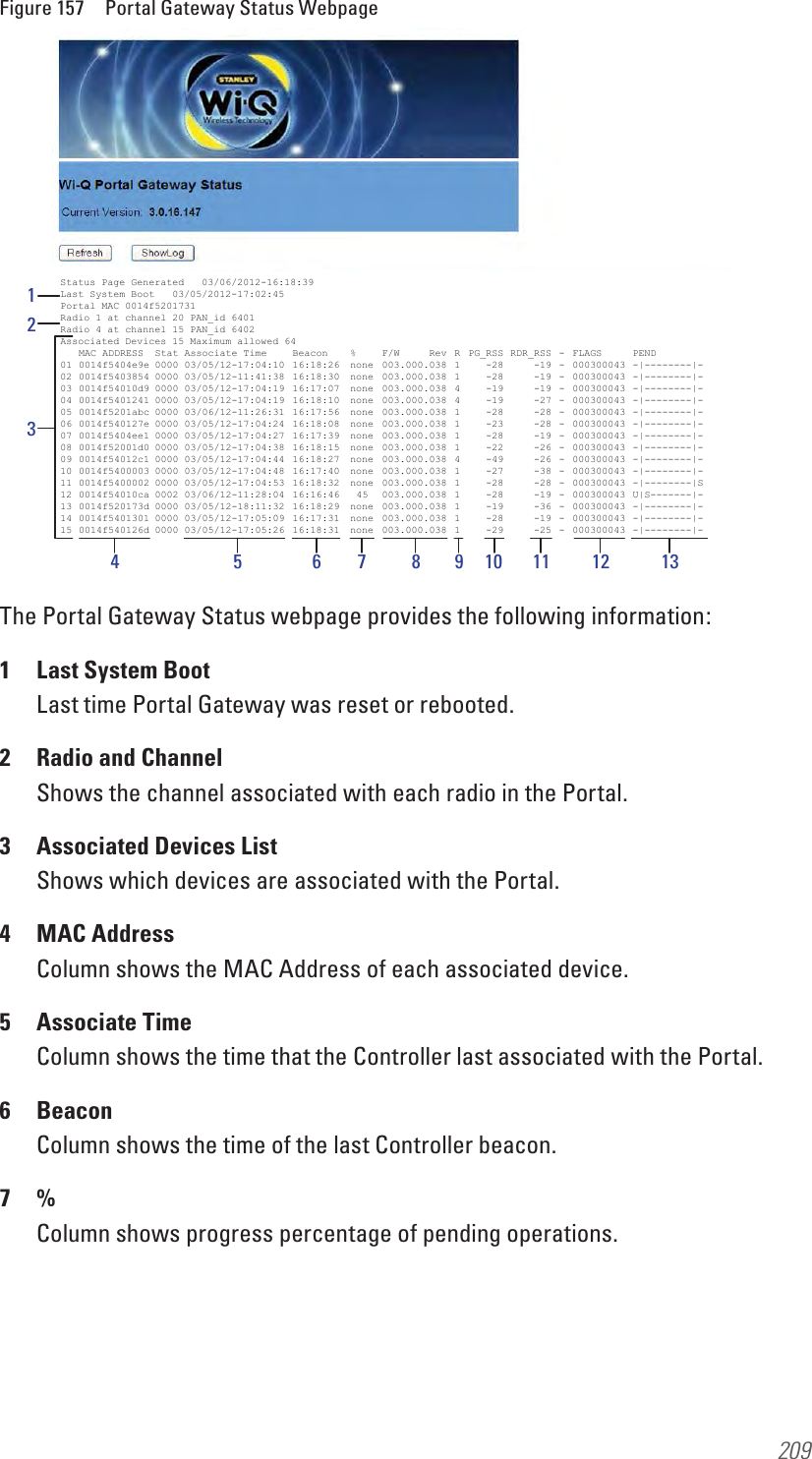
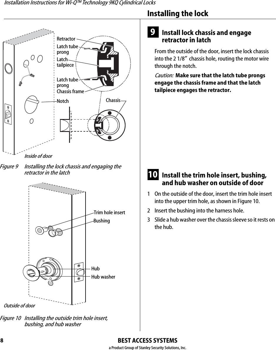
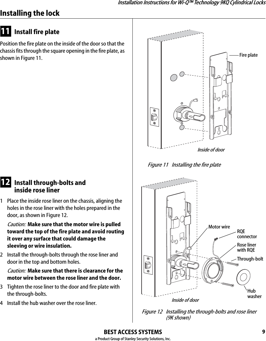
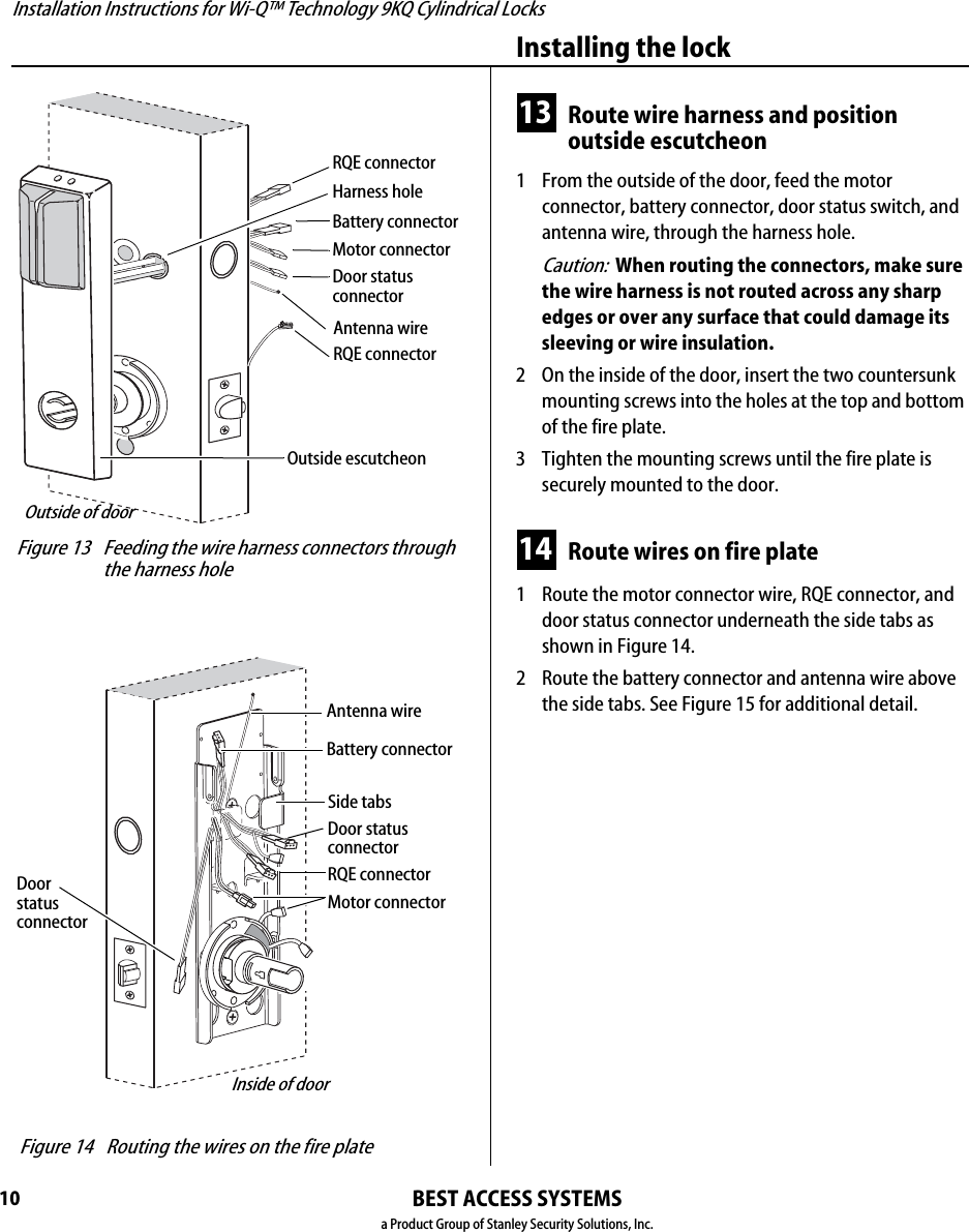
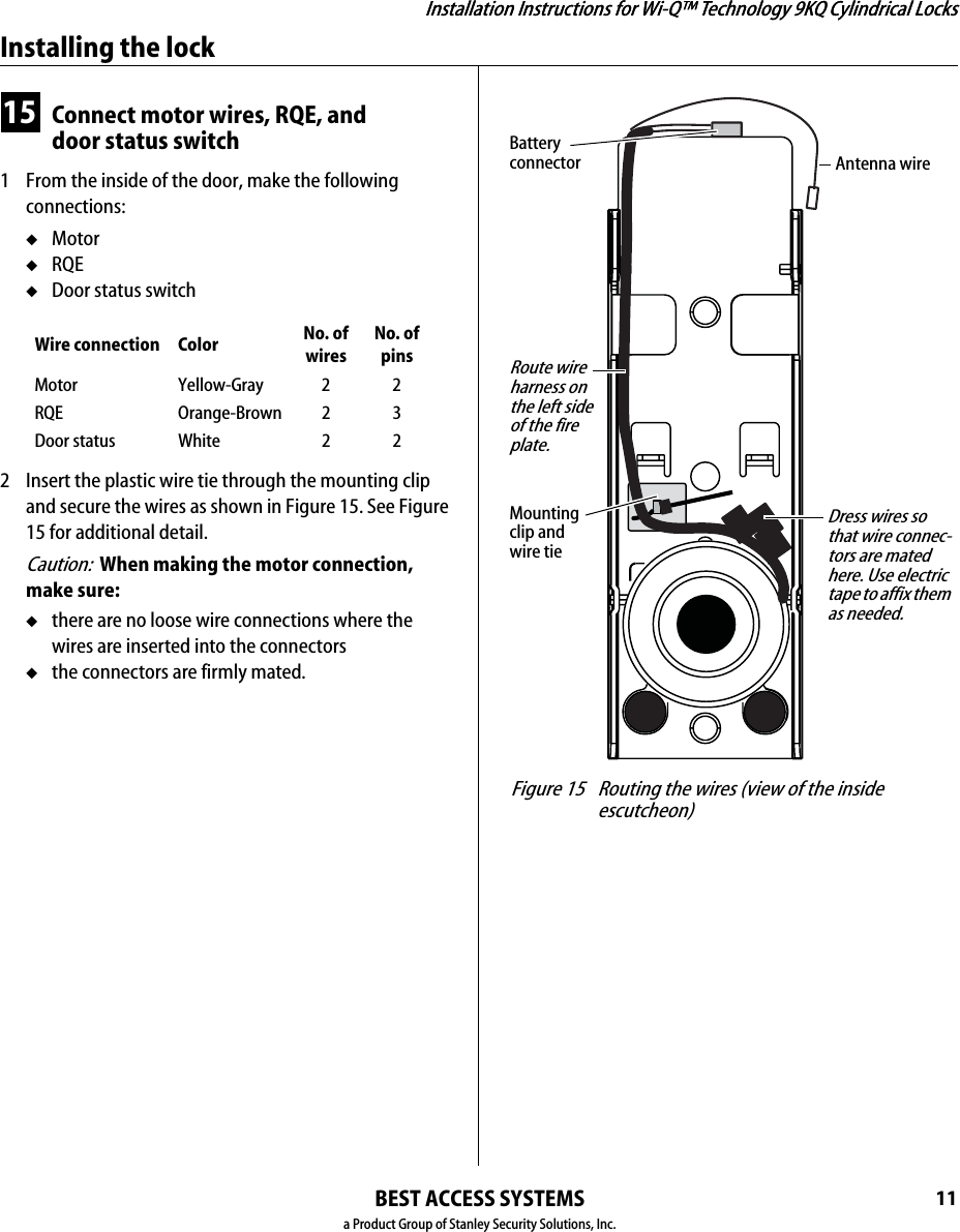
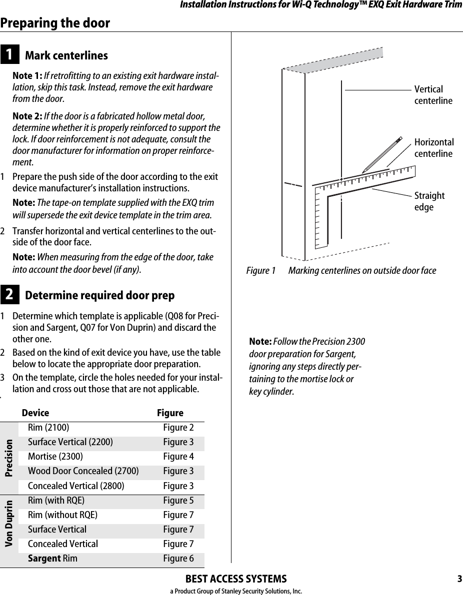
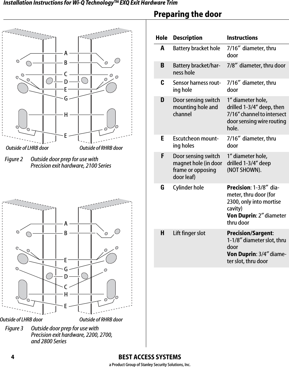
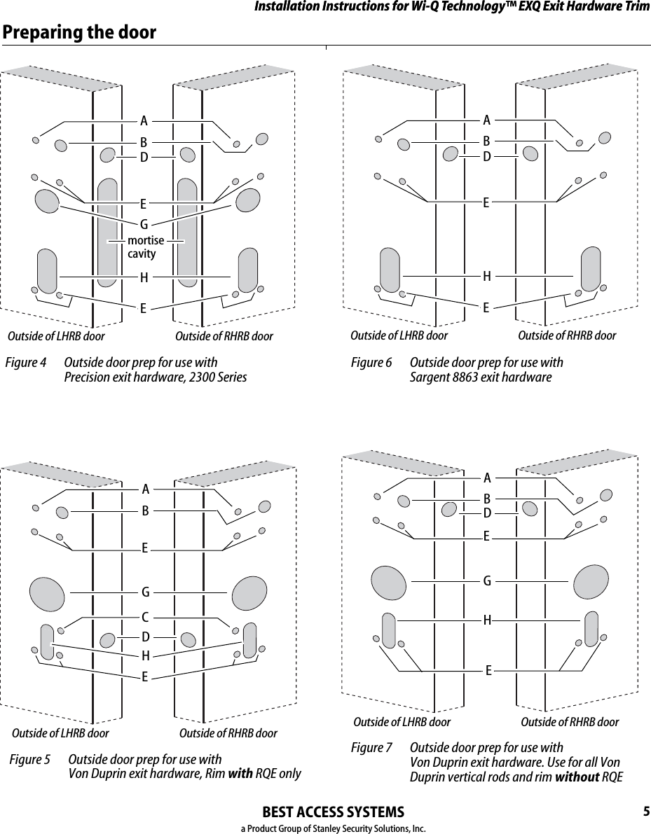
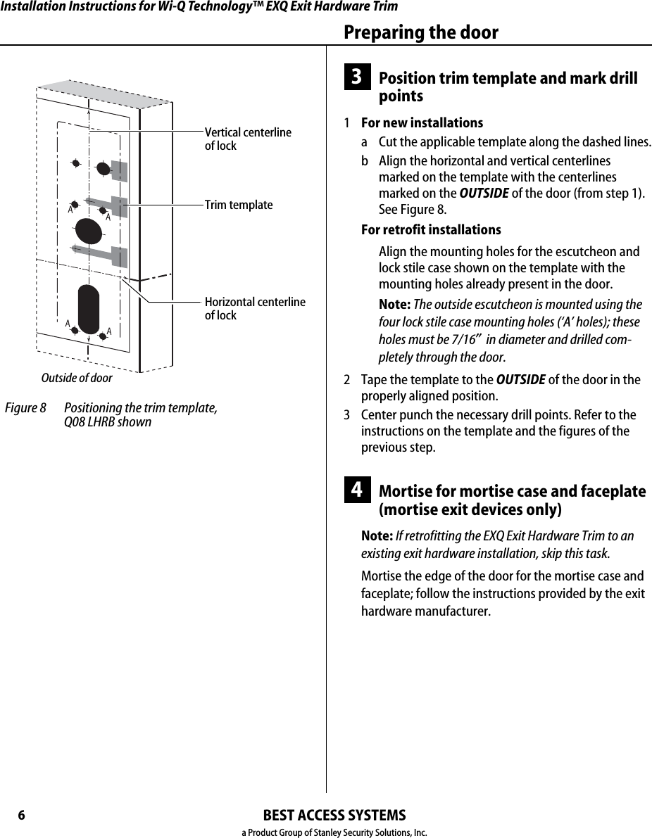
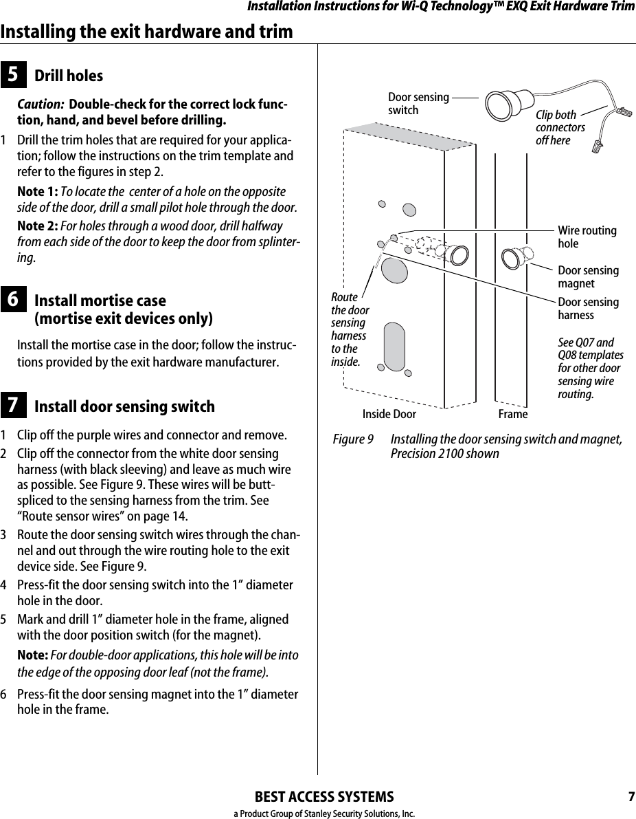
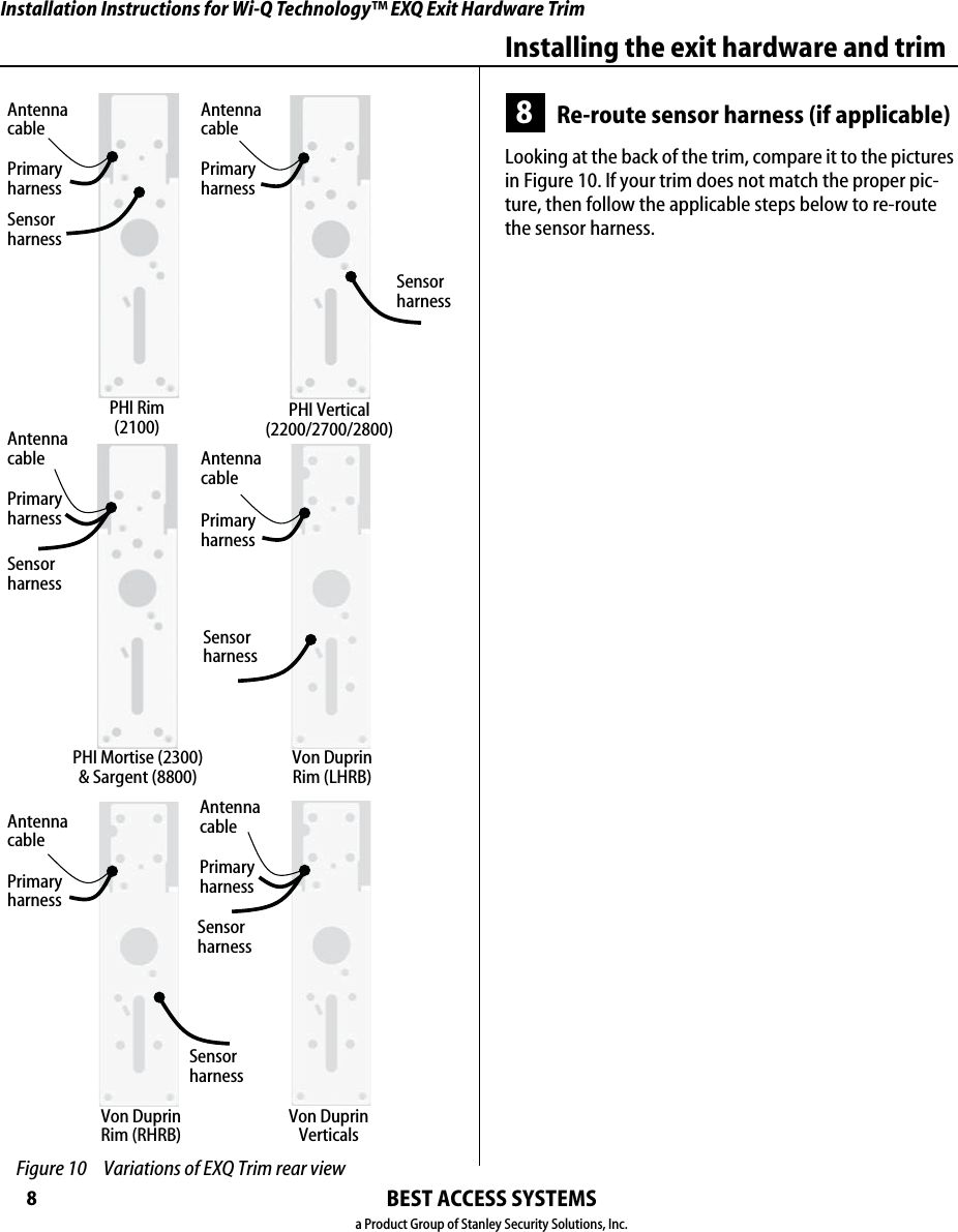
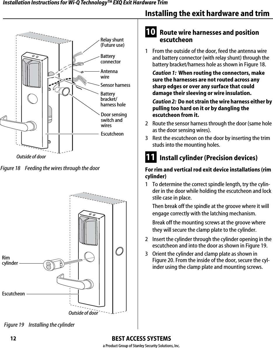
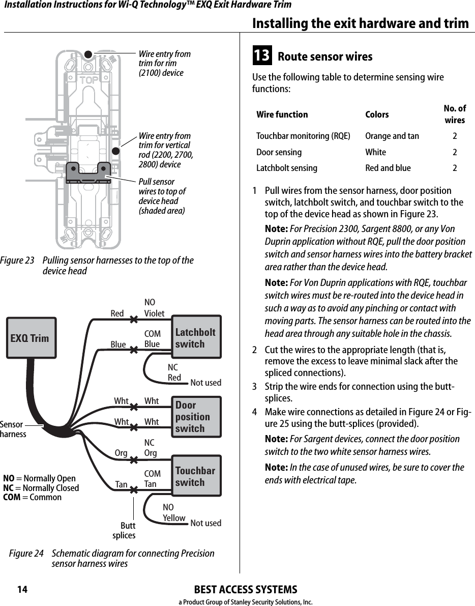
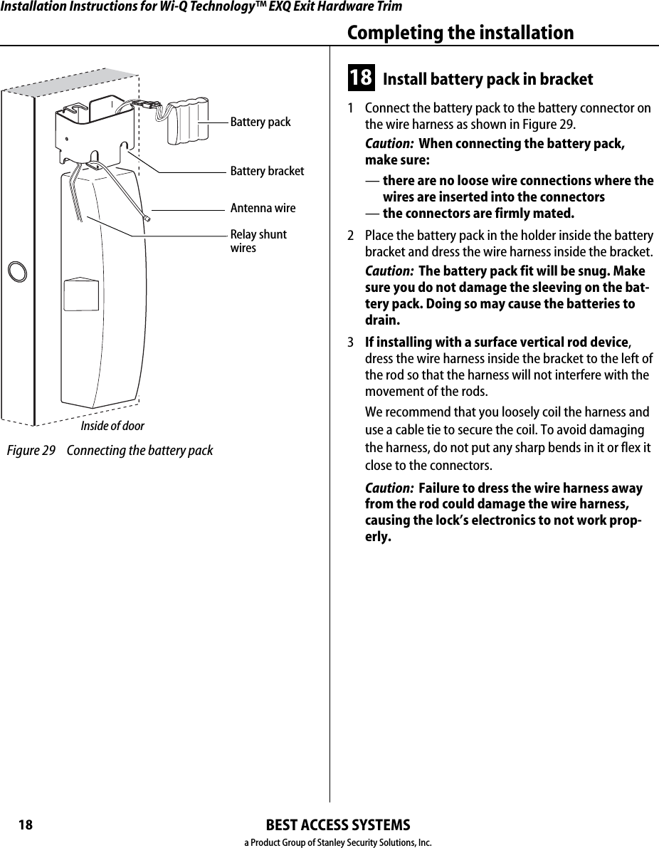
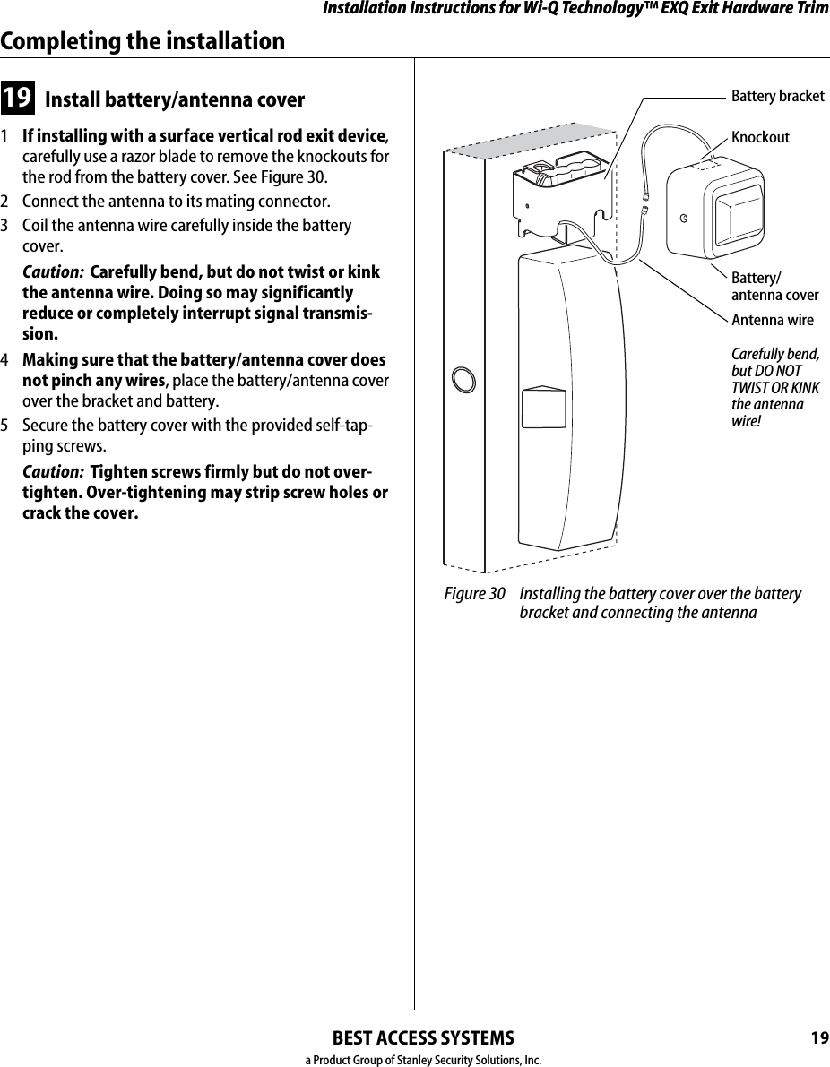
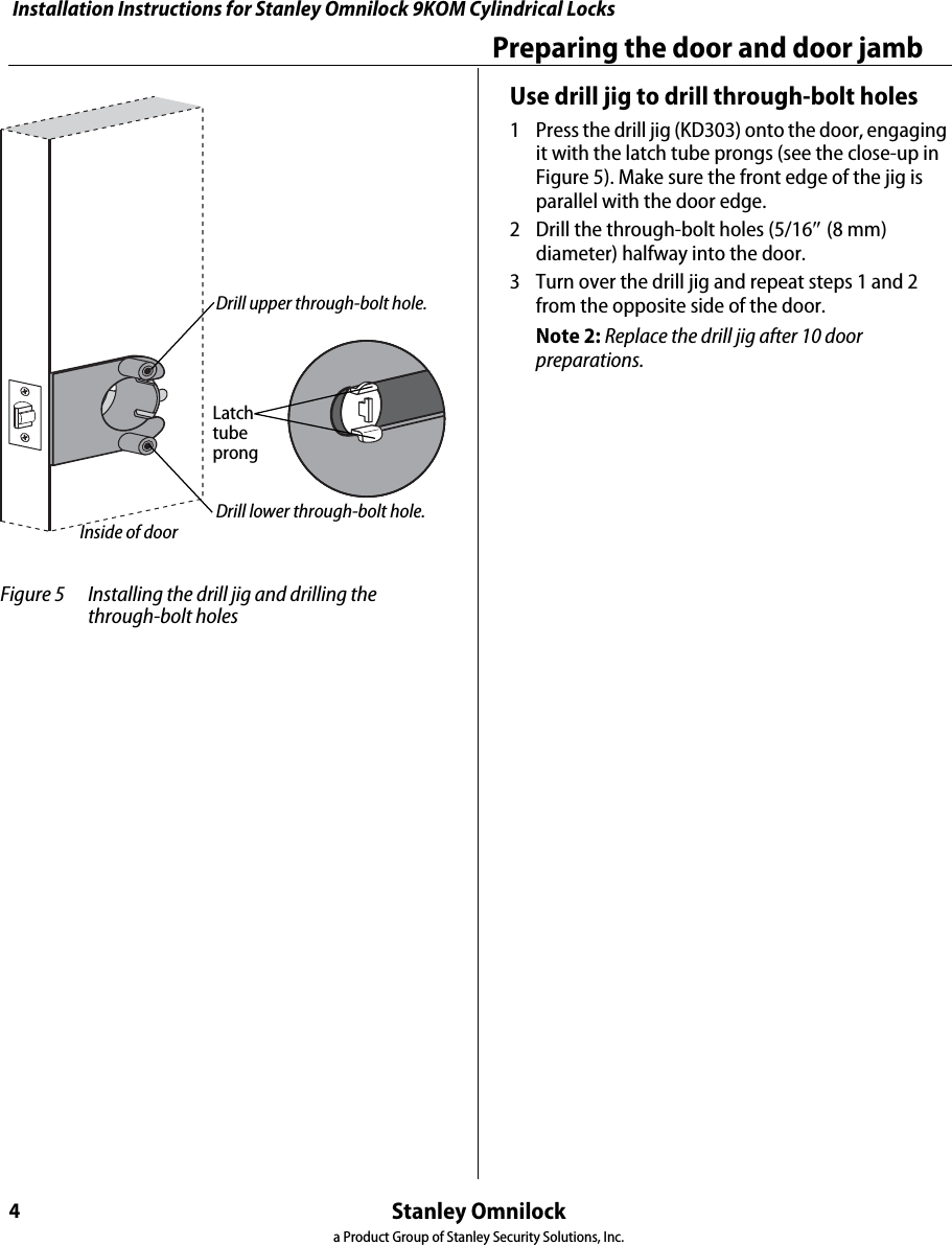
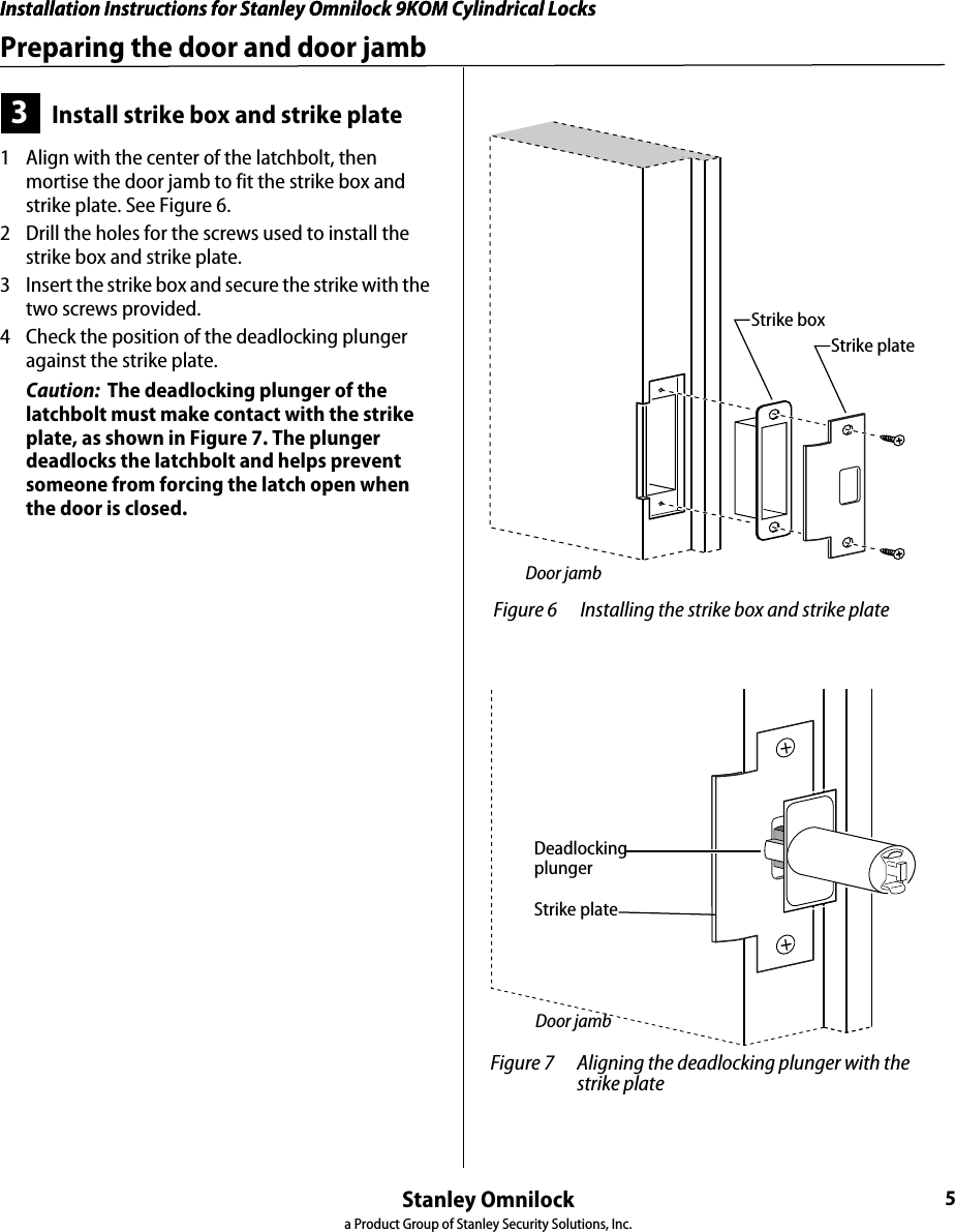
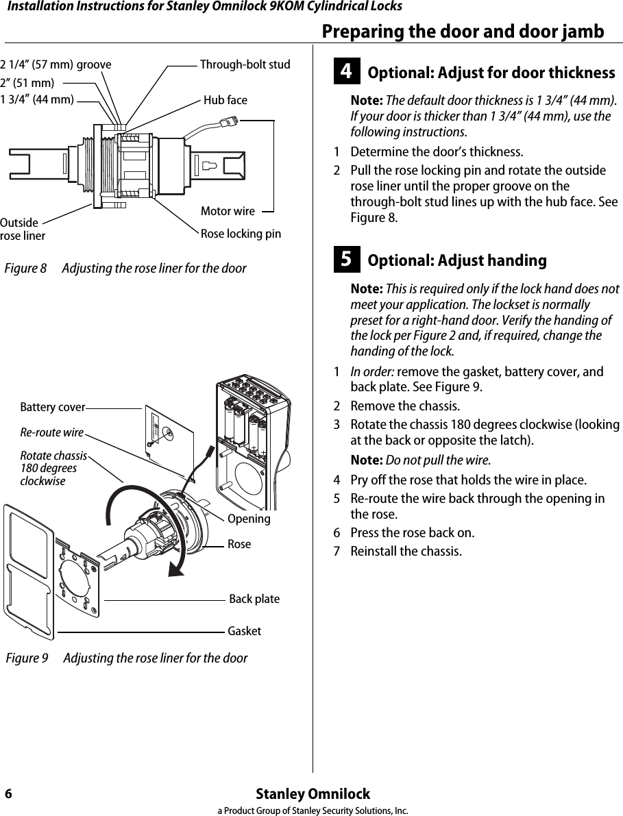
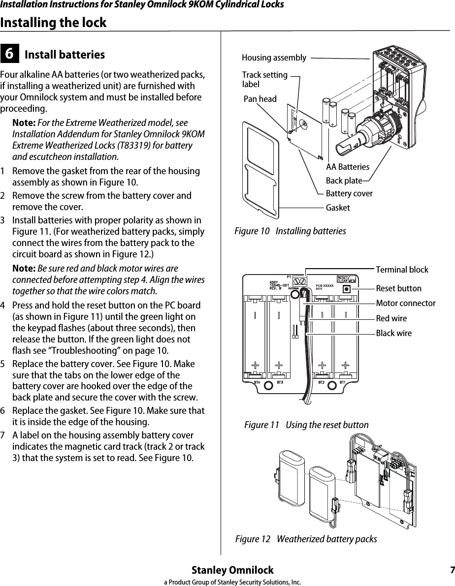
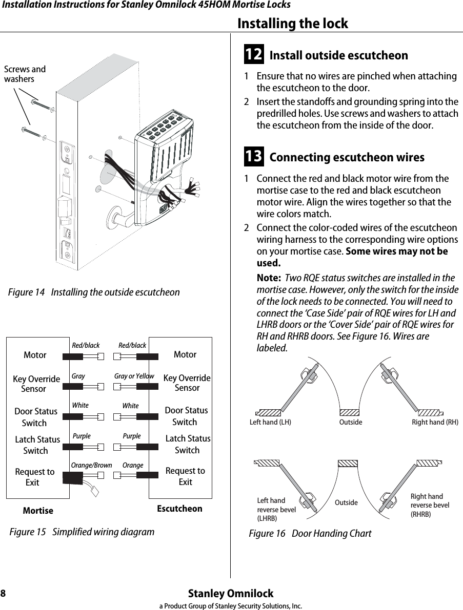
![Installation Instructions for Wi-Q Technology™ EXQ Exit Hardware TrimBEST ACCESS SYSTEMSa Product Group of Stanley Security Solutions, Inc.13Installation Instructions for Wi-Q Technology™ EXQ Exit Hardware TrimInstalling the exit hardware and trimFor mortise exit device installations (mortise cylinder)1 For doors less than 2″ in thickness, place the cylin-der ring provided on the cylinder.2 Rotate the cylinder cam to the 12 o’clock position, as shown in Figure 21.3 Using a cylinder wrench (ED211), insert the cylinder through the cylinder opening in the escutcheon and screw the cylinder into the mortise case. Make sure that the figure-8 hole is in the 12 o’clock position.Caution: Do not screw the cylinder in too tightly. Doing so may cause users to be locked out.12 Install exit hardware and secure escutcheonFor Precision 2200, 2700 and 2800 exit devices only■Drill a 5/16” hole through the front part of the chassis as shown in Figure 22. (This hole is used to pass the sensor harness and door position switch wires into the chassis area.)For all exit devices1 Make any adjustments to the exit hardware necessary for compatibility with lever function outside trim.2 Install the exit hardware (lock stile case, touch bar assembly, latches and rods [if applicable], and related hardware); follow the instructions provided by the exit hardware manufacturer. Note: The escutcheon is secured on the outside of the door by the screws used to mount the lock stile case on the inside of the door. Caution: When securing the escutcheon, make sure that it does not pinch any wires. Figure 20 Rim cylinder componentsRim cylinderScrewsSpindleClamp plateOrient the curve toward the cylinder. Figure 21 Mortise cylinder componentsMortise cylinderCam in 12 o’clock positionView of the back of the cylinder Figure 22 Drilling 5/16” hole for Precision 2200, 2700, and 2800 exit devices onlyDrill 5/16” hole thru the face of the chassis here.Drill ONLY for 2200, 2700 and 2800 devices](https://usermanual.wiki/Stanley-Security-Solutions/SDC2K.Manual-3/User-Guide-3028746-Page-61.png)