Star Solutions 6-09-01-00-1 iCell COMPAC GSM IP-RAN 1900MHz CPU(wo CPU) DC GPS User Manual
Star Solutions International Inc iCell COMPAC GSM IP-RAN 1900MHz CPU(wo CPU) DC GPS Users Manual
UserManual.wiki
>
Star Solutions
>
6 09 01 00 1 User Manual
Users Manual
Navigation menu
Upload a User Manual
Namespaces
Wiki Guide
HTML
PDF
Info
Views
User Manual
Discussion / Help
Navigation

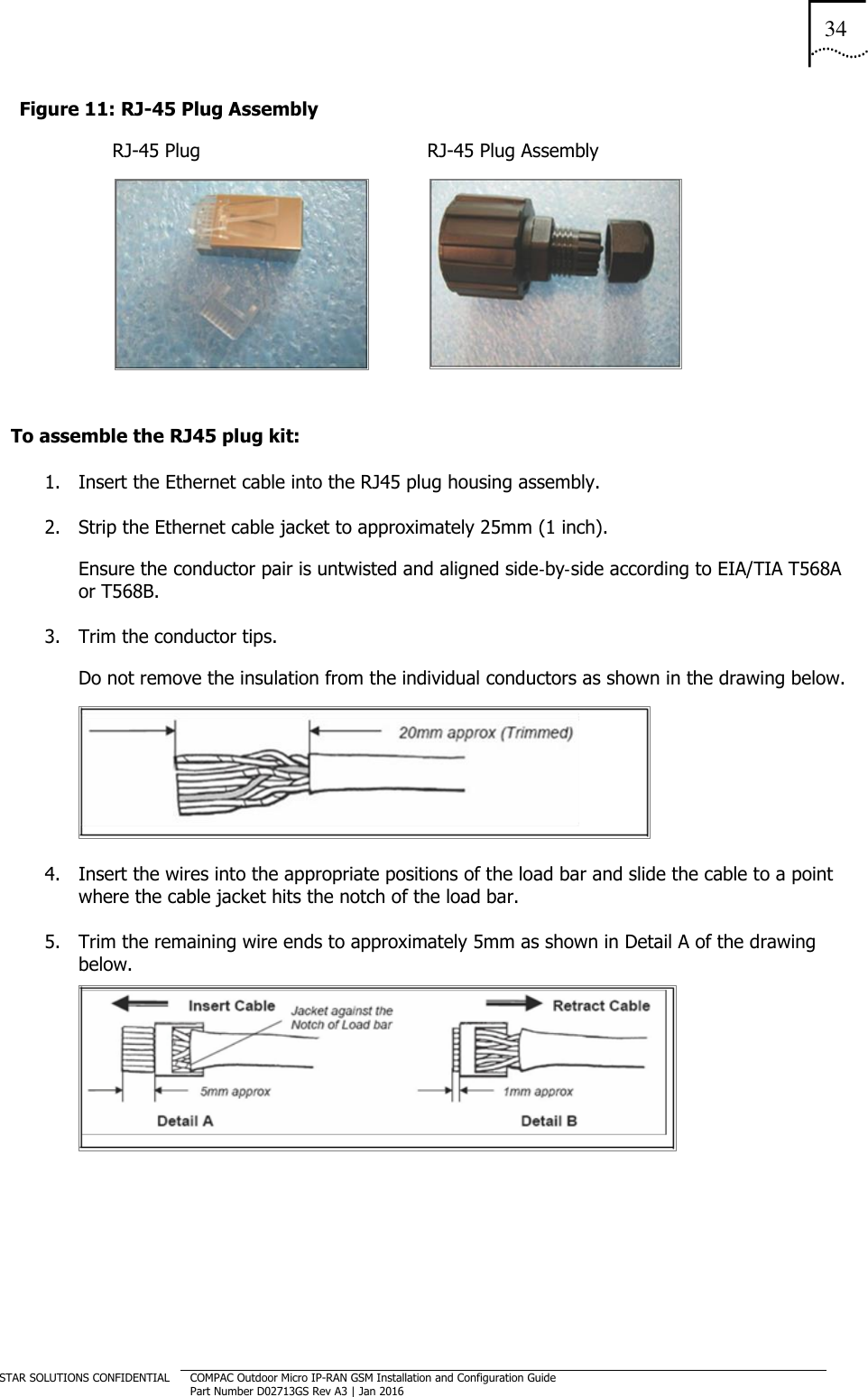
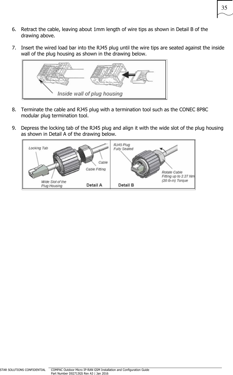
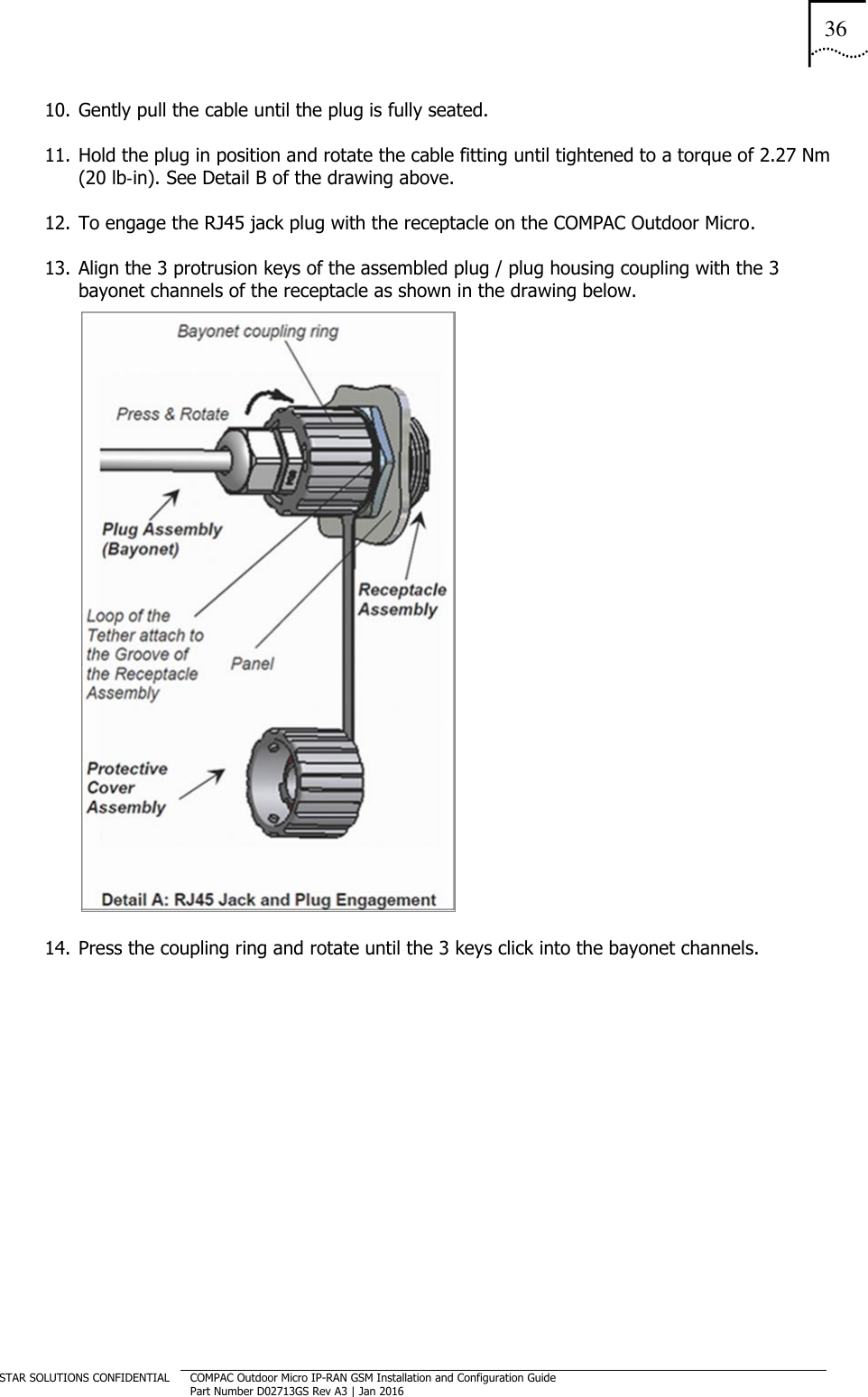
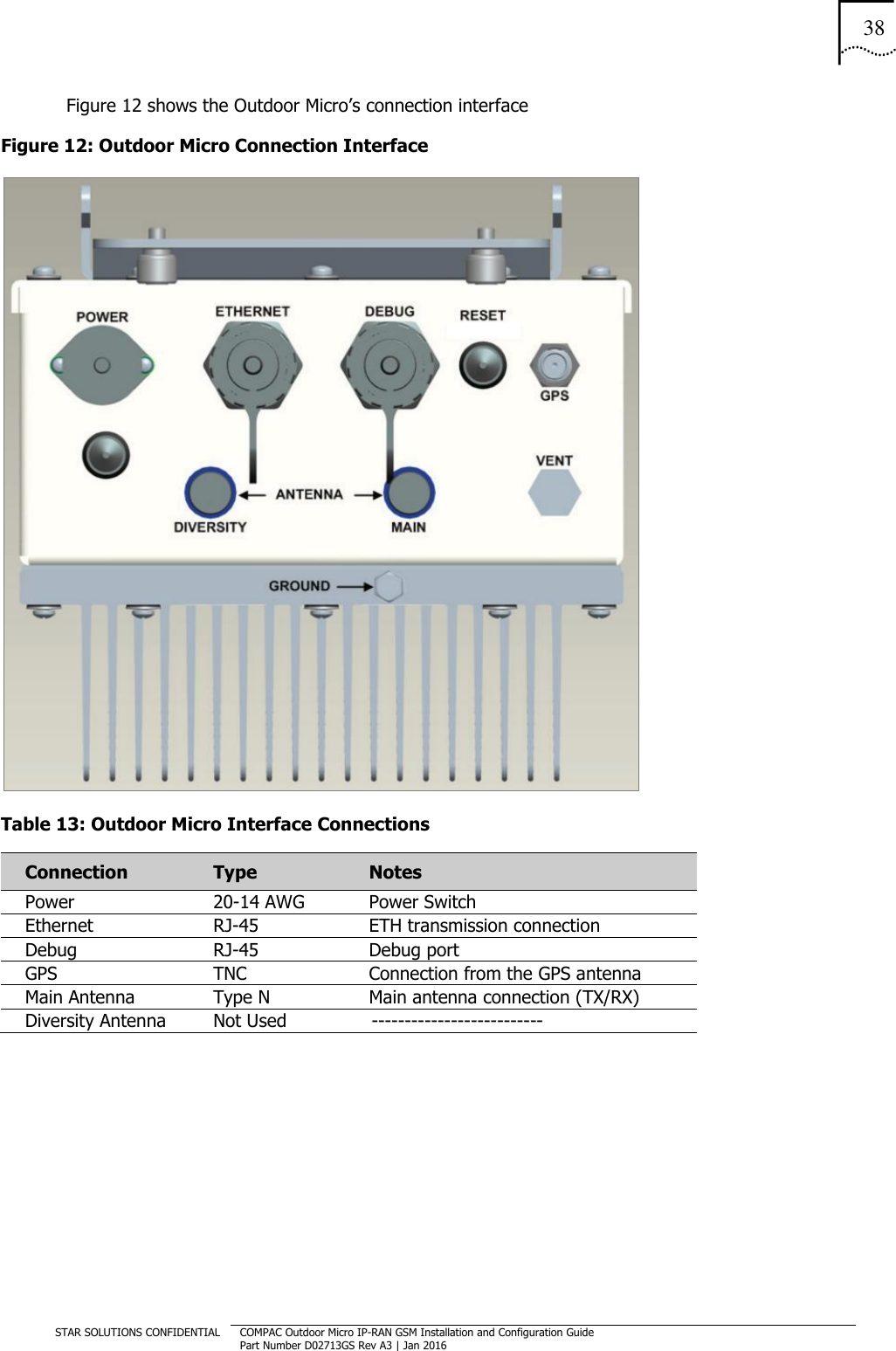
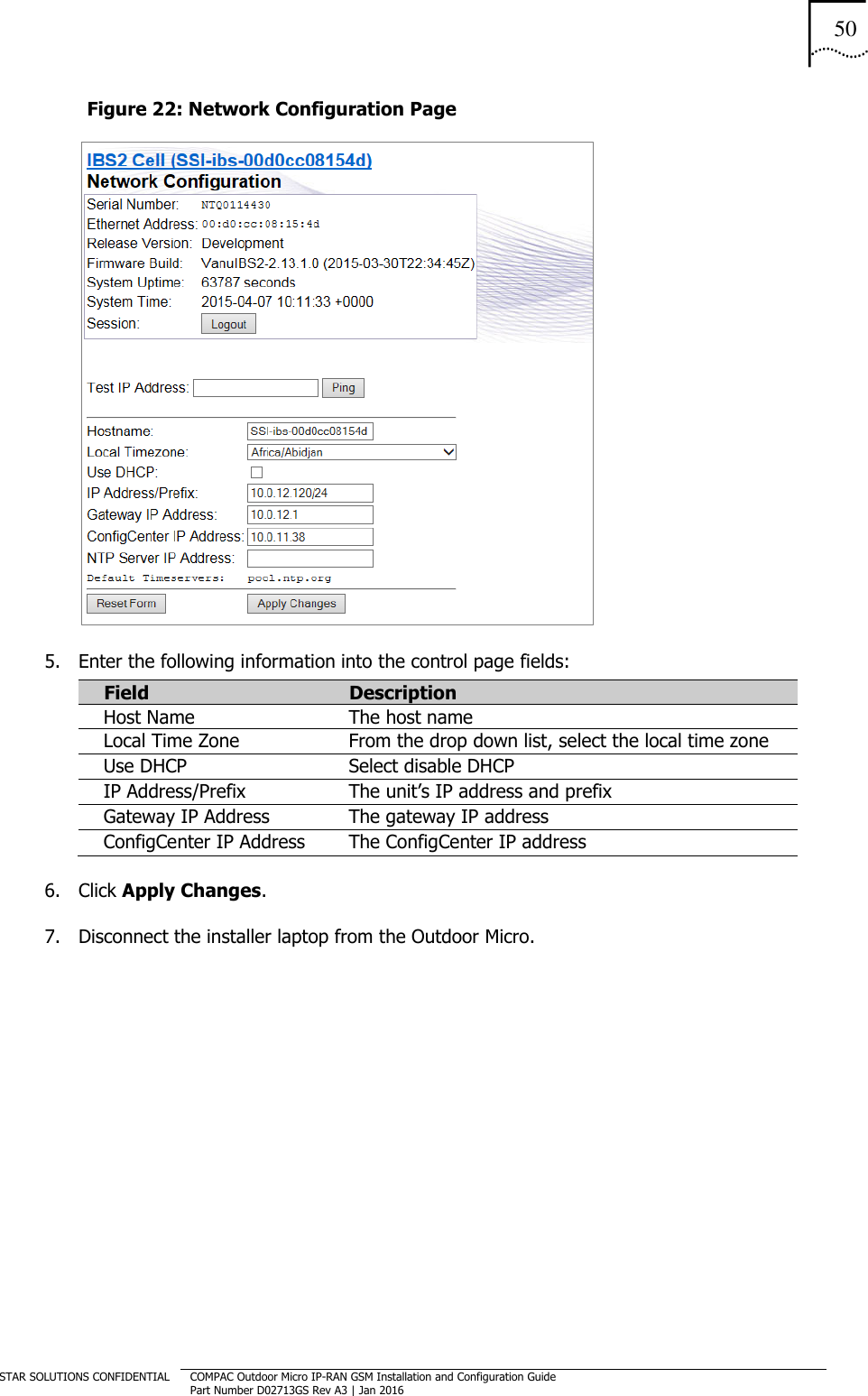
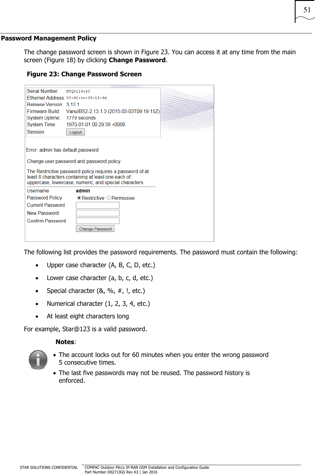
![A REGULATORY NOTICES RF Maximum Permissible Exposure (MPE) Exhibit Requirements FCC Part 1, Section 1.1307 states the following: Part 22 Subpart H devices are excluded from routine environmental evaluation when the operating total power level of all channels is less than 1640 Watts EIRP. Part 24 Subpart E (Broadband PCS) devices are excluded from routine environmental evaluation when the operating total power level of all channels is less than 3280Watts EIRP. No antenna is supplied with this unit. The installer must not exceed the antenna gain limitations related to total power requirements in order to be excluded from routine environmental evaluation. To comply with the Maximum Permissible Exposure (MPE) requirements for general population that are specified under FCC Part 1 ‐ Section 1.1310 ‐ Table 1, the maximum power density resulting from the composite Effective Isotopic Radiated Power (EIRP) from the antenna connected to this equipment must be limited to the maximum permissible exposure as stated below: Power density limit for Band Class 0 = f/1500 = 0.58 mW/cm² Power density limit for Band Class 1 = 1 mW/cm² This value can be achieved by multiple combinations of RF output, antenna gain, and distance from the antenna when energized. The minimum safe distances from a radiating structure in order to be excluded from routine environmental evaluation are: For Band Class 0 (TX: 869–894 MHz RX: 824–849 MHz) d (safe distance) = 4.7 m For Band Class 1 (TX: 1930 1990 MHz RX: 1850 1910 MHz) d (safe distance) = 5.1 m The MPE is expressed as follows: Power Density Pd (mW/cm²) = EIRP/[4*Pi*d²] Where d = distance from the antenna expressed in cm. EIRP expressed in mW = 10[TX Power (dBm) + Ant Gain(dBi)]/10 TX Power (dBm) = 10*log[Tx Power (mW)] As an example with the transmitter running at 5 watts output into an antenna with a gain of 10 dBi, the minimum safe distance from the antenna to ensure exposure would be: 63 cm to remain below 1 mW/cm2 for the 1900 PCS band, and 83 cm to remain below 0.58 mW/cm2 for the 800 Cellular band. When installing the antenna, the above relationship should be used to ensure the combination of power, antenna gain, and distance is such that the maximum permissible power density is not exceeded. Different combinations of output power and antenna gain will result in different minimum safe distances.](https://usermanual.wiki/Star-Solutions/6-09-01-00-1/User-Guide-2904895-Page-52.png)