Star Solutions 6-09-01-00-1 iCell COMPAC GSM IP-RAN 1900MHz CPU(wo CPU) DC GPS User Manual
Star Solutions International Inc iCell COMPAC GSM IP-RAN 1900MHz CPU(wo CPU) DC GPS Users Manual
Users Manual

ALL-IP GSM
iCell COMPAC IP-RAN
Outdoor Micro GSM
Installation and Configuration Guide
Part Number D02713GS Rev A3

iCell COMPAC IP-RAN
Outdoor Micro GSM
Installation and Configuration Guide
Part Number D02713GS Rev A3

iii
STAR SOLUTIONS CONFIDENTIAL
iCell COMPAC IP-RAN Outdoor Micro GSM Installation and Configuration Guide
Part Number D02713GS Rev A3 | Jan 2016
STAR SOLUTIONS CONFIDENTIAL
The information contained herein is the property of Star Solutions International Inc. "Star Solutions" and is strictly
confidential. Except as expressly authorized in writing by Star Solutions, the holder shall keep all information
contained herein confidential, in whole or in part, from disclosure and dissemination to third parties.
COPYRIGHT NOTICE
Copyright © 2016, Star Solutions International Inc. All rights reserved. No part of this documentation may be
reproduced in any form or by any means or used to make any derivative work (such as translation, transformation,
or adaptation) without prior written permission from Star Solutions.
Star Solutions, the Star Solutions logo, iCell and Sonata are registered trademarks or trademarks of Star Solutions
International Inc. and its subsidiaries. All other brand and product names may be registered trademarks and are the
property of their respective owners.
Star Solutions reserves the right to revise this documentation and to make changes in content from time to time
without obligation on the part of Star Solutions to provide notification of such revision or change.
Star Solutions provides this documentation without warranty of any kind, either implied or expressed, including, but
not limited to, the implied warranties of merchantability and fitness for a particular purpose. Star Solutions may make
improvements or changes in the product(s) and/or the program(s) described in this documentation at any time.
UNITED STATES GOVERNMENT LEGENDS:
If you are a United States government agency, then this documentation and the software described herein are
provided to you subject to the following:
United States Government Legend: All technical data and computer software is commercial in nature and developed
solely at private expense. Software is delivered as Commercial Computer Software as defined in DFARS
252.227?7014 (June 1995) or as a commercial item as defined in FAR 2.101(a) and as such is provided with only
such rights as are provided in Star Solutions's standard commercial license for the Software. Technical data is
provided with limited rights only as provided in DFAR 252.227?7015 (Nov 1995) or FAR 52.227?14 (Dec 2007),
whichever is applicable. You agree not to remove or deface any portion of any legend provided on any licensed
program or documentation contained in, or delivered to you in conjunction with, this documentation.
Table of Contents
Introduction................................................................................................................................ 6
Product Overview: All‐IP System Architecture ............................................................................... 6
Outdoor Micro Functionality ......................................................................................................... 7
Technical Specifications ............................................................................................................... 7
MCPA ......................................................................................................................................... 8
Order of Tasks ............................................................................................................................ 9
Conventions ................................................................................................................................ 9
Technical Support ..................................................................................................................... 10
Warranty Support ..................................................................................................................... 11
1. PREREQUISISTES ................................................................................................................ 13
About this chapter..................................................................................................................... 13
Site Requirements ..................................................................................................................... 13
Installer Requirements .............................................................................................................. 13
Network Planning Requirements ................................................................................................ 15
2. SITE PREPARATION ............................................................................................................ 16
About This Chapter ................................................................................................................... 16
Site Planning ............................................................................................................................ 16
Site Requirements ..................................................................................................................... 17
Inspecting and Verifying Site Requirements ................................................................................ 19
3. OUTDOOR MICRO INSTALLATION ...................................................................................... 22
About this chapter..................................................................................................................... 22
Unpacking the Shipment ............................................................................................................ 22
Installation Notes ...................................................................................................................... 23
Mounting Options for the Outdoor Micro ..................................................................................... 23
Pole Mounting Instructions ........................................................................................................ 24
Wall Mounting........................................................................................................................... 26
Floor Mounting ......................................................................................................................... 28
Mounting the MCPA ................................................................................................................... 30
Making the Power Cable ............................................................................................................ 31
4. INTERFACE CONNECTIONS ................................................................................................. 37
About this chapter..................................................................................................................... 37
Grounding ................................................................................................................................ 39
RF Connections ......................................................................................................................... 39
Ethernet Connections ................................................................................................................ 41
GPS Antenna Connection ........................................................................................................... 42
Power Connection ..................................................................................................................... 43
Reset Button ............................................................................................................................. 43
Status LED................................................................................................................................ 43

5
STAR SOLUTIONS CONFIDENTIAL
iCell COMPAC IP-RAN Outdoor Micro GSM Installation and Configuration Guide
Part Number D02713GS Rev A3 | Jan 2016
MCPA Interface Connections ...................................................................................................... 44
5. OUTDOOR MICRO IP CONFIGURATION .............................................................................. 46
About this Chapter .................................................................................................................... 46
Outdoor Micro IP Configuration Procedure .................................................................................. 46
Password Management Policy .................................................................................................... 51
RF Maximum Permissible Exposure (MPE) Exhibit Requirements .................................................. 52
6
STAR SOLUTIONS CONFIDENTIAL
iCell COMPAC IP-RAN Outdoor Micro GSM Installation and Configuration Guide
Part Number D02713GS Rev A3 | Jan 2016
ABOUT THIS GUIDE
Introduction
This reference guide provides a high level description of the iCell COMPAC Outdoor Micro.
This chapter lists the guide conventions and related documentation and the order of which initial
configuration tasks should be completed, and describes how to contact customer service.
This chapter includes:
Product Overview: All-IP System Architecture
Outdoor Micro Functionality
MCPA
Order of Tasks
Conventions
Technical Support
Warranty Support
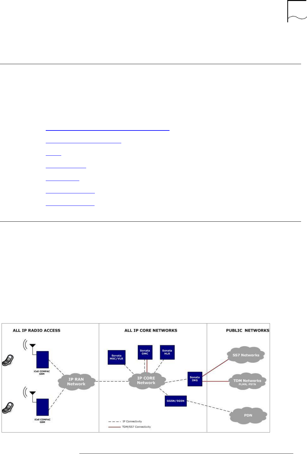
Product Overview: All‐IP System Architecture
The Star Solutions iCell COMPAC GSM IP-RAN is a complete outdoor GSM and GPRS enabled base
station system. The unit is passively cooled, avoiding the need for fans or air conditioning, and is
specifically designed for low power consumption. The iCell COMPAC GSM IP-RAN is a natural fit
with alternative energy sources such as solar or wind powered hybrid systems when commercial
power is not readily available.
The iCell COMPAC GSM IP-RAN comes with the inherent features common to all of Star Solutions’
All-IP mobile network architecture including IP interface to the network, local call routing, support
for all transmission networks, including satellite, and significant reduction of backhaul bandwidth.
The system architecture is shown in Figure 1
Figure 1: All‐IP GSM Network Architecture
7
STAR SOLUTIONS CONFIDENTIAL
iCell COMPAC IP-RAN Outdoor Micro GSM Installation and Configuration Guide
Part Number D02713GS Rev A3 | Jan 2016
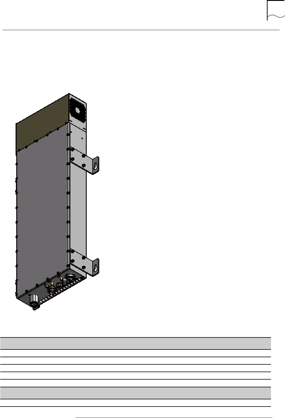
Outdoor Micro Functionality
The Outdoor Micro provides an All‐IP GSM wireless cell site capable of providing up to 10 watts RF
power output. The Outdoor Micro provides single‐sector coverage with a two transceivers (TRX)
capacity. The Outdoor Micro offers an additional level of integration by supporting an optional Base
Station controller (BSC) module. Figure 2 shows the Outdoor Micro’s exterior view.
Figure 2: External View of Outdoor Micro Module
Technical Specifications
Table 1 lists the Outdoor Micro’s technical specifications.
Table 1: iCell COMPAC Technical Specifications
Capacity/Performance
Configuration
Single sector 2TRX
RF Output Power
5 Watts in 2 TRX mode
10 Watts in single TRX mode
25 Watts per TRX in 2 TRX mode (requires external MCPA)
Frequency Band
Supported Bands
850, 900, 1800, 1900 MHz
Hardware
Dimensions
72.5 cm H x 22 cm W x 18.2 cm D (28.5 x 8.7 x 7.1 inch)
Weight
20 kg
Input Voltage
-48 VDC
Power Consumption
Less than 80 Watts in typical operating conditions
Options
Mounting brackets for pole, wall or floor
Environmental
Operating Temperature
-40 to + 55°C
Storage Temperature
-40 to + 70°C
Humidity
5-95% non-condensing
8
STAR SOLUTIONS CONFIDENTIAL
iCell COMPAC IP-RAN Outdoor Micro GSM Installation and Configuration Guide
Part Number D02713GS Rev A3 | Jan 2016
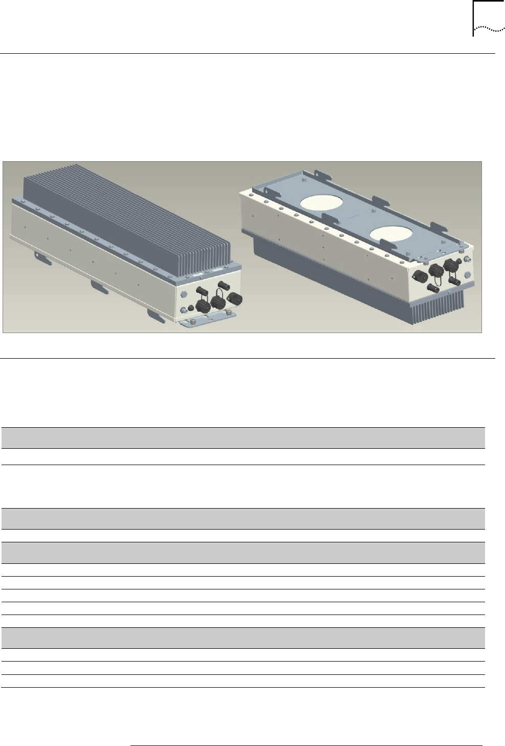
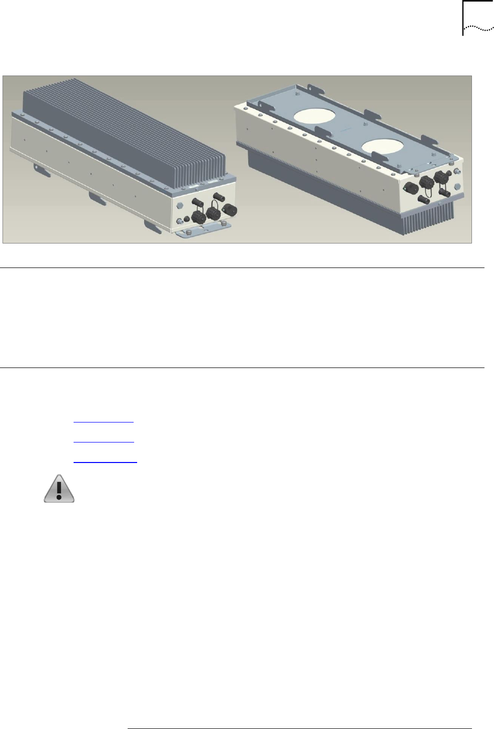
MCPA
The COMPAC outdoor Micro can be integrated with a Multi-Carrier-Power-Amplifier (MCPA) to allow
higher transmit power. Figure 3 shows an exterior view of the MCPA. Table 2 provides the MCPA’s
technical specifications. The MCPA allow maximum power output of 25 Watt per carrier (TRX)
Figure 3 MCPA External View
Table 2 MCPA Technical Specifications
Hardware
Dimensions
72 cm H x 25 cm W x 8.4 cm D (28.3 x 9.8 x 3.3 inch)
Weight
10 kg
Input Voltage
48 VDC
Power Consumption
300 Watts in typical operating conditions
Options
Mounting brackets for wall or floor
Environmental
Operating Temperature
0 to + 40°C
9
STAR SOLUTIONS CONFIDENTIAL
iCell COMPAC IP-RAN Outdoor Micro GSM Installation and Configuration Guide
Part Number D02713GS Rev A3 | Jan 2016
Order of Tasks
This guide has 6 main sections showing the tasks to be carried out and in what order they are to be
done:
Prerequisites
Site Preparation
Installation
Interface Connection
Configuring the Outdoor Micro
Regulatory Notices
Note: Release notes are issued with some products. If the information in the
release notes differs from the information in this guide, follow the instructions
given in the release notes.
Conventions
This guide may contain notices, figures, screen captures, and certain text conventions.
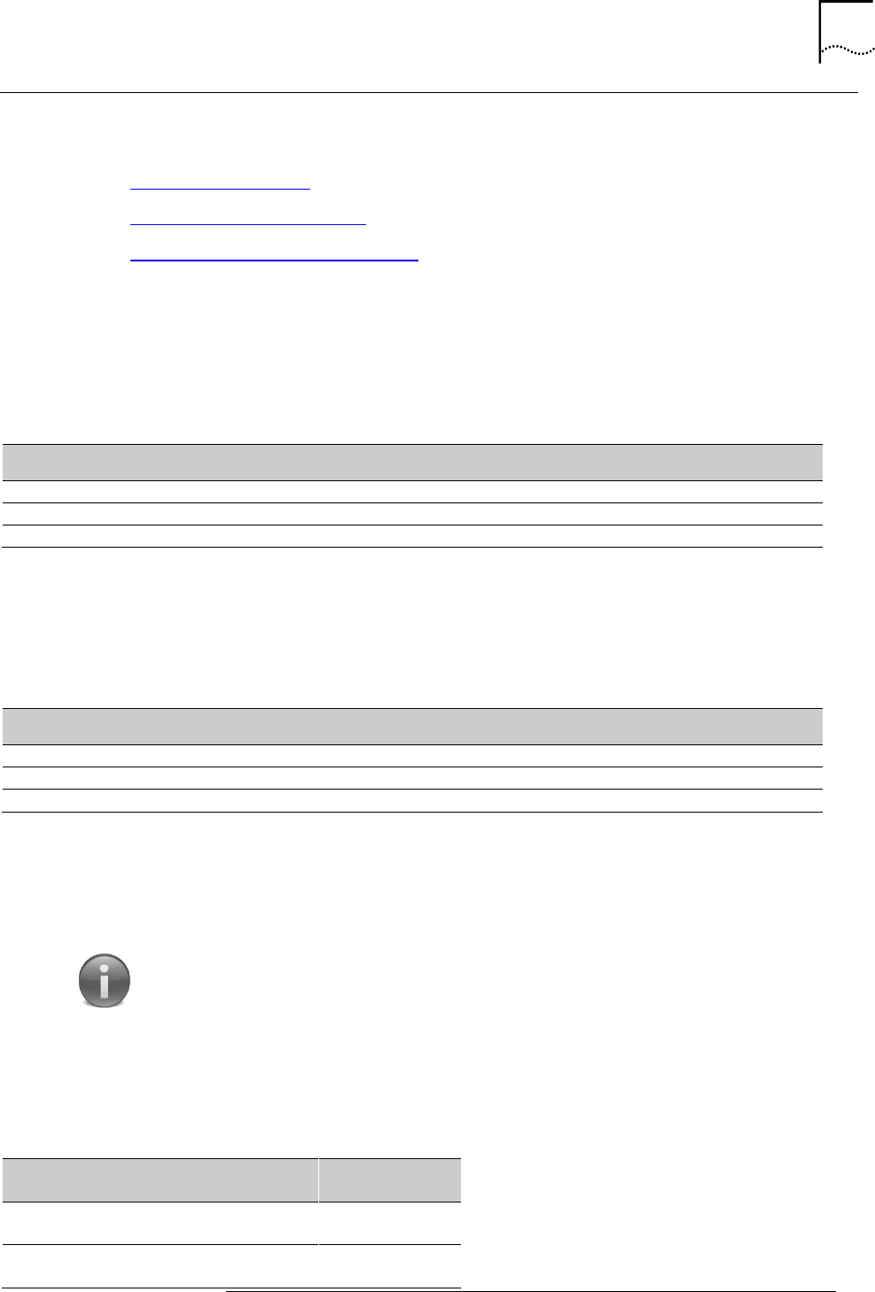
Notice Icons
This guide has icons placed throughout this manual to alert you to and highlight particular parts of
the text or instructions. Table 3 lists the notice icons used in this guide.
Table 3: Notice Icon Descriptions
Icon
Notice Type
Description
Information Note
Information that contains
important features or instructions
but is not hazard-related.
Caution or Warning
Cautions are preceded with the word Caution.
This type of caution indicates a potentially
hazardous situation which, if not avoided,
may result in minor or moderate injury. It
may also alert against unsafe practices and
potential program, data, system, or device
damage.
Warnings are preceded with the word
Warning. This type of warning indicates a
potentially hazardous situation which, if not
avoided, could result in death or serious
injury.
Caution or Warning due to
potential electrical hazard
Cautions due to potential electrical hazards
are preceded with the word Caution. This
type of caution indicates a potential electrical
hazard. This hazard, if not avoided, may
result in minor or moderate injury. It may
also alert against unsafe practices and
potential program, data, system, or device
damage.

10
STAR SOLUTIONS CONFIDENTIAL
iCell COMPAC IP-RAN Outdoor Micro GSM Installation and Configuration Guide
Part Number D02713GS Rev A3 | Jan 2016
Warnings due to potential electrical hazards
are preceded with the word Warning. This
type of warning indicates a potential electrical
hazard. This hazard, if not avoided, could
result in death or serious injury.
ESD
Information that indicates proper grounding
precautions are required before handling a
product.
Figures and Screen Captures
This guide provides figures and screen captures as examples. These examples contain sample data.
This data may vary from the actual data on an installed system. Table 4 lists text conventions used
in this guide.
Table 4: Text Convention Descriptions
Convention
Description
Text represented as a
screen display
This typeface represents text that appears on a terminal screen, for
example login:.
Text represented as a
user entry
This typeface represents commands entered by the user, for example, cd
$HOME.
Text represented as
menu, sub-menu,
tab and field names
This typeface represents all menu, sub-menu, tab, and field names
within procedures.
For example: On the File menu, click New.
Text represented by
<variable>
This typeface represents a required variable.
For example:
<filename>
Technical Support
The Star Solutions Product Support Team provides all technical support services necessary for
business and professional needs. Our product experts deliver Tier 1, 2 and 3 technical support
directly to new and contract-entitled customers including the following services:
Basic Support Package: Non-emergency technical support
Premium Support Package: 24 hours a day, 7 days a week, and 365 days a year
Emergency technical support
The Star Solutions Service Guide outlines the specific details for obtaining technical support. The
guide is available from a sales account manager. Refer to the Service Guide for services and options
specific to individual support plans, including guidelines for problem severity and the technical
resolution escalation process.
Obtaining Technical Assistance
Star Solutions maintains a global presence through its Technical Response and Service Centers.
These centers are available for technical telephone support to entitled customers during normal
business hours.
Before contacting technical support, please have this information available:
Product information
o Software and hardware revisions

11
STAR SOLUTIONS CONFIDENTIAL
iCell COMPAC IP-RAN Outdoor Micro GSM Installation and Configuration Guide
Part Number D02713GS Rev A3 | Jan 2016
o Serial numbers
Problem description
o Symptoms
o Known causes
Trouble locating and clearing attempts
For information about customer service, including support, training, code releases and updates,
contracts, and documentation, contact us at: http://www.starsolutions.com/support/support-portal/
Service Centers Operational Hours
North America/CALA Region: 09:00–18:00 Pacific Time (UTC-8:00)
EMEA/Asia Pacific Region: 09:30–18:30 Indian Standard Time (UTC+5:30)
Warranty Support
Star Solutions provides its customers warranty support per the terms of the Star Solutions Warranty
Statement for their equipment. Customers who require warranty support should contact the Star
Solutions Customer Service Center as specified in the customer service guide or at:
http://www.starsolutions.com/support/support-portal/


1. PREREQUISISTES
About this chapter
This chapter describes the prerequisites to installing the Outdoor Micro. It chapter includes:
Site Requirements
Installer Requirements
Network Planning Requirements
Password and Username Assignment
Site Requirements
The Outdoor Micro is designed to be pole, wall, or floor mounted.
The network operator is responsible for supplying supporting components, cabling, and the
necessary operating environment for the Outdoor Micro. See Inspecting and Verifying Site
Requirements for details.
Warning: The network operator is responsible for site grounding and
lightning protection. Verify all grounding, power connections and lightning
protection to see that it meets or exceeds the local electrical standards.
Installer Requirements
This section includes:
Skills and knowledge
Supporting Documentation
Required Tools and Materials
Test Client Hardware
Skills and knowledge
The installer of this Outdoor Micro must have general electrical circuit and telecommunications
knowledge.
Supporting Documentation
The following documents are required to install, configure and test the Micro Outdoor:
Outdoor Micro Installation and Initial Configuration Guide (this guide)
Network Planning Document
Engineering specifications for the site and network are required for any configuration of
parameters after installation and initial configuration. The Network Planning Document also
provides the necessary inputs for the Network Planning Requirements section.

14
STAR SOLUTIONS CONFIDENTIAL
iCell COMPAC IP-RAN Outdoor Micro GSM Installation and Configuration Guide
Part Number D02713GS Rev A3 | Jan 2016
Required Tools and Materials
The tools required for the installation of the Outdoor Micro are listed in below:
10mm hex wrench
¾ inch hex wrench
Power drill (rotary impact hammer) and (½ inch) concreate drill bit
Side cutter or wire cutter
Tape measure
Straight edge or chalk line
Pencil or marker
Shop Vacuum
Note: The tools needed for connecting the wall mount assembly are not
listed here. They are the responsibility of the site manager or the installer.
Test Client Hardware
In order to communicate with the Outdoor Micro, the following tools and cables are required:
Laptop: A laptop PC, also called the Test Client, is needed for the installation, configuration,
verification and network integration of the Outdoor Micro. The minimum PC requirements are:
Processor: 1.3 GHz
Operating System: Microsoft® Windows© XP Pro/Vista/7
Memory: 512 MB
Hard Drive: 10 GB
CD ROM Drive: 48X
USB Port: Optional
Ethernet Port and Card: 10/100
Cables: Several different cables are needed for the installation, configuration, verification and
network integration of the Outdoor Micro.
Antenna Cables: Main and diversity N male connectors (10 W output)
Power Cables: 20 to 14 AWG power cabling. See Making the Power Cable.
Grounding Cable: 20 AWG (minimum) with a crimp lug on one end
Backhaul Ethernet Cable: CAT-6 or CAT-5 with 2 RJ-45 connector ends. See Ethernet
Connections.
15
STAR SOLUTIONS CONFIDENTIAL
iCell COMPAC IP-RAN Outdoor Micro GSM Installation and Configuration Guide
Part Number D02713GS Rev A3 | Jan 2016
Network Planning Requirements
This section includes:
IP Address Assignment
Access Network IP Addressing
Password and Username Assignment
IP Address Assignment
The test client is used to connect the NE’s and they must be on the same subnet. The needed IP
addressing information is listed in Table 5. Obtain them from the project or site engineer and write
them down for future reference.
Table 5: Required IP Addressing for the Test Client
Test Client
Value
IP Address 1
Subnet Mask 1
Default Gateway 1
Access Network IP Addressing
Table 6 lists the IP addressing information required for the Access Network. Obtain them from the
project or site engineer and write them down for future reference.
Table 6: Required IP Addressing
Test Client
Value
BSC IP Address
BTS IP Address
Configuration Center IP Address
Password and Username Assignment
The Outdoor Micro has default username and passwords configured. New site‐specific usernames
and passwords can be assigned during installation and configuration or new usernames and
passwords can be configured later by the operator.
Note: Changing usernames and passwords is not mandatory, but site-specific values will
be required if usernames and passwords are changed.
Table 7 lists the usernames and passwords required to connect. Have the site‐specific usernames
and passwords ready before installation begins so that login information can be changed to site‐
specific values.
Table 7: Login Configuration for Site (http)
BSS Component
Default
Username
Default
Password
configcenter
root
tel_os
BTS
admin
admin
16
STAR SOLUTIONS CONFIDENTIAL
iCell COMPAC IP-RAN Outdoor Micro GSM Installation and Configuration Guide
Part Number D02713GS Rev A3 | Jan 2016
2. SITE PREPARATION
About This Chapter
This chapter describes how to prepare the site for the installation of the Outdoor Micro.
This chapter includes:
Site Planning
Site Requirements
Inspecting and Verifying Site Requirements
Site Planning
The Outdoor Micro has specific structural, electrical, and telecommunications requirements. When
selecting and preparing a site, specific personnel and documents must be available to ensure the
device is installed correctly and safely.
Site Planning includes planning for:
Required Personnel
Required Site‐Specific Information
Site Planning Checklist
Site Plans and Floor Plans
Required Personnel
For safety, Star Solutions recommends at least two people be assigned to install the Outdoor Micro.
Installers should be experienced in the installation and configuration of telecommunications
equipment.
Required Site‐Specific Information
When preparing a site for installation of an Outdoor Micro, obtain this site‐specific information:
General site information
Power information:
o Grounding data
o Power‐level data
Environmental documents:
o Temperature records
o Humidity tests
Site wiring lists
Security alarm system data
Fire system data

17
STAR SOLUTIONS CONFIDENTIAL
COMPAC Outdoor Micro IP-RAN GSM Installation and Configuration Guide
Part Number D02713GS Rev A3 | Jan 2016
Site Planning Checklist
The following checklist is provided to assist in the site planning procedure. After completing the
required steps, check them off, or refer back to this list, to ensure all site planning requirements are
met:
Reviewing personnel requirements
Gathering related documentation
Verifying power
Verifying the grounding
Verifying alarms
Verifying site conditions
Verifying weather conditions
Verifying temperature control
Reviewing standard equipment rack location specifications
Reviewing equipment mounting guidelines
Preparing the site for the Outdoor Micro
Site Plans and Floor Plans
Generate a site plan and floor plan for equipment layout. The Outdoor Micro should be
installed according to the clearances outlined in Space Clearance Requirements.
Site Requirements
This section outlines the requirements for the site where the Outdoor Micro is to be installed:
Site Power Requirements
Site External Grounding Requirements
Other Cable Grounding Requirements
Mounting Options
Space Clearance Requirements
The required tools, hardware, and network information are outlined Required Tools and Materials.
Site Power Requirements
DC Power: The DC Outdoor Micro must be supplied with ‐68 VDC to ‐40 VDC, nominal
voltage is -48 VDC.
Waterproofing: To maintain the product’s IP65 rating, the power cable attached to the
unit must provide a waterproof connection to the Lightning Protection Unit (LPU).
Cable Requirements: The fitting supplied with the Outdoor Micro accepts a cable
diameter in the range of 22 to 27 mm (0.880 to 1.065”). The cable must also be
appropriately temperature rated.

18
STAR SOLUTIONS CONFIDENTIAL
COMPAC Outdoor Micro IP-RAN GSM Installation and Configuration Guide
Part Number D02713GS Rev A3 | Jan 2016
Site External Grounding Requirements
Site Grounding Responsibility: Site grounding is the responsibility of the customer. All
grounding and power connections should be made according to local standards.
Ground Rods: Several factors affect external grounding. The most significant factor is the
resistance of ground rods, which is directly related to soil resistivity in the immediate vicinity
of the rod. The resistivity of the soil determines how many rods are needed and their
dimensions.
Other Cable Grounding Requirements
All other cables such as telephone cables, data cables, and power cables
must
be connected to the
single‐point ground and must employ impulse/surge suppressors.
Cables between any two cabinets must be shielded and employ a messenger cable. The messenger
cable must be bonded to the respective building ground at each corner. The shields must be bonded
to the ground at each ring.
Note: A messenger cable is made of stranded steel and supports aerial
cable between poles.
Mounting Options
The Outdoor Micro has three different installation kits:
Pole Mounting: The Outdoor Micro supports installation on steel, concrete, or wood poles
with diameter from 12 to 30 cm (5 to 12 inches). See Pole Mounting for details.
Wall Mounting: The Outdoor Micro supports installation on wood, concrete, masonry,
grout‐filled‐block, and hollow‐block walls. See Wall Mounting for details.
Floor Mounting: The Outdoor Micro supports installation on various floor types. See Floor
Mounting for details.
Space Clearance Requirements
The Outdoor Micro requires space around the unit to allow for proper routing of the cables as well
as viability for the GPS antenna.
Vertical Clearance: The Outdoor Micro requires a minimum clearance for cable
connections at the bottom of the cabinet. Cables for the antennas have differing turn
radiuses which affect the required vertical clearance.
Area Clearance: The Outdoor Micro requires sufficient area clearance to provide adequate
space for the bending radius necessary for the required RF cables.
GPS Antenna Clearance: The GPS antenna installed on the top of the Outdoor Micro
mounting assembly requires unobstructed upward visibility for satellite acquisition. Do not
install any solid metal constructions above the Outdoor Micro.

19
STAR SOLUTIONS CONFIDENTIAL
COMPAC Outdoor Micro IP-RAN GSM Installation and Configuration Guide
Part Number D02713GS Rev A3 | Jan 2016
Inspecting and Verifying Site Requirements
Inspect the physical location where the Outdoor Micro is to be installed, and verify the location
meets the minimum requirements outlined in this section.
Note: If site conditions do not comply with the instructions in this manual,
contact the site manager, facility representative or other responsible
individuals at once. Do not proceed with the installation until the site
conditions are satisfied.
This section includes:
Installer Safety Precautions
Fire Protection for Indoor Installation
Verifying Site Conditions
Installer Safety Precautions
The installer must take appropriate safety precautions as specified by local standards. These
include:
Providing on‐site fire extinguishers. See Fire Protection for Indoor Installations.
Use of appropriate safety equipment and clothing
Insuring on‐site first aid support is available
Where possible, work under a buddy system to insure someone is available to help in case
of an emergency
Fire Protection for Indoor Installations
Notes:
Fire protection applies only to indoor installations.
If there is no fire suppression equipment installed, contact the site manage or facility
representative before starting.
Have at least two 5-lb. ABC class portable fire extinguishers on the premises before
starting installation.
Install fixed fire suppression equipment. Possible types are:
Halon gas system
Carbon dioxide (CO2) system
Sprinkler system (Star Solutions recommends using "dry pipe" sprinkler systems that
remove all power to a room before filling the overhead sprinklers with water.)
Verifying Site Conditions
The site must be clean and free of obstructions.
Warnings:
External cabling must be supported by appropriate cable racks not attached to the
Outdoor Micro. Otherwise, the weight of the cabling may reduce the ability of the
system to withstand Zone 4 Seismic activity.

20
STAR SOLUTIONS CONFIDENTIAL
COMPAC Outdoor Micro IP-RAN GSM Installation and Configuration Guide
Part Number D02713GS Rev A3 | Jan 2016
Installation of ancillary equipment (power supplies, cable racks, batteries, etc.) is the
responsibility of the installer.
Verify that:
The outdoor temperature is within the specified limits for the equipment (see Technical
Specifications).
There are no obstructions.
Any dust and/or water in the area is cleared away.
Do not place components or other equipment directly on the ground.
During inclement weather conditions, use adequate protection, such as a tent, to protect
the equipment from precipitation or windblown debris.

3. OUTDOOR MICRO INSTALLATION
About this chapter
This chapter describes how to install the Outdoor Micro. It chapter includes:
Unpacking the Shipment
Installation Notes
Mounting Options for the Outdoor Micro
Pole Mounting Instructions
Wall Mounting Instructions
Floor Mounting Instructions
Mounting the MCPA
Making the Power Cable
Assembling the Ethernet Cable
Unpacking the Shipment
Inspect the packing container immediately on arrival at the installation site to verify that no damage
has occurred during shipment.
Cautions:
If any damage is observed, notify the shipper
at once
to start the insurance claim
process. Do not open or unpack the container until an insurance adjuster has inspected
the containers for exterior damage. If possible, take photographs for your records.
Do not
open the Outdoor Micro casing. No user serviceable parts are located inside.
Servicing is to be done only by Star Solutions-qualified service personnel.
Do not discard the shipping carton. Use it to package the Outdoor Micro to Star
Solutions for repair or replacement.
If the container appears to be in satisfactory condition, open it and carefully unpack the equipment.
Verify the contents and quantities against the packing list. The Shipped Component List in this
section lists the components shipped with the Outdoor Micro.
Shipped Component List:
Outdoor Micro Unit: 1
Connector Kit: 1
Ferrite Bead (260 Ohm @ 100 MHz): 2
Mounting Kit: 1
The Outdoor Micro Module is shown in Figure 4.
23
STAR SOLUTIONS CONFIDENTIAL
COMPAC Outdoor Micro IP-RAN GSM Installation and Configuration Guide
Part Number D02713GS Rev A3 | Jan 2016
Figure 4: External View of Outdoor Micro Module
Installation Notes
Prior to configuring the Outdoor Micro, verify the following:
All connectors that are not connected are terminated.
The shielding of all coaxial connections is grounded.
Mounting Options for the Outdoor Micro
The Outdoor Micro can be:
Pole Mounted
Wall Mounted
Floor Mounted
Warnings:
Disconnect all power going to or coming from the Outdoor Micro before removing or
installing it.
Do not open the Outdoor Micro casing. No user serviceable parts are located inside.
Servicing is to be done only by Star Solutions-qualified service personnel.
The Outdoor Micro mounting kit comes with the GPS antenna and cable guard pre‐
installed. Care must be taken to ensure that the GPS antenna cable is not damaged
during installation.
24
STAR SOLUTIONS CONFIDENTIAL
COMPAC Outdoor Micro IP-RAN GSM Installation and Configuration Guide
Part Number D02713GS Rev A3 | Jan 2016
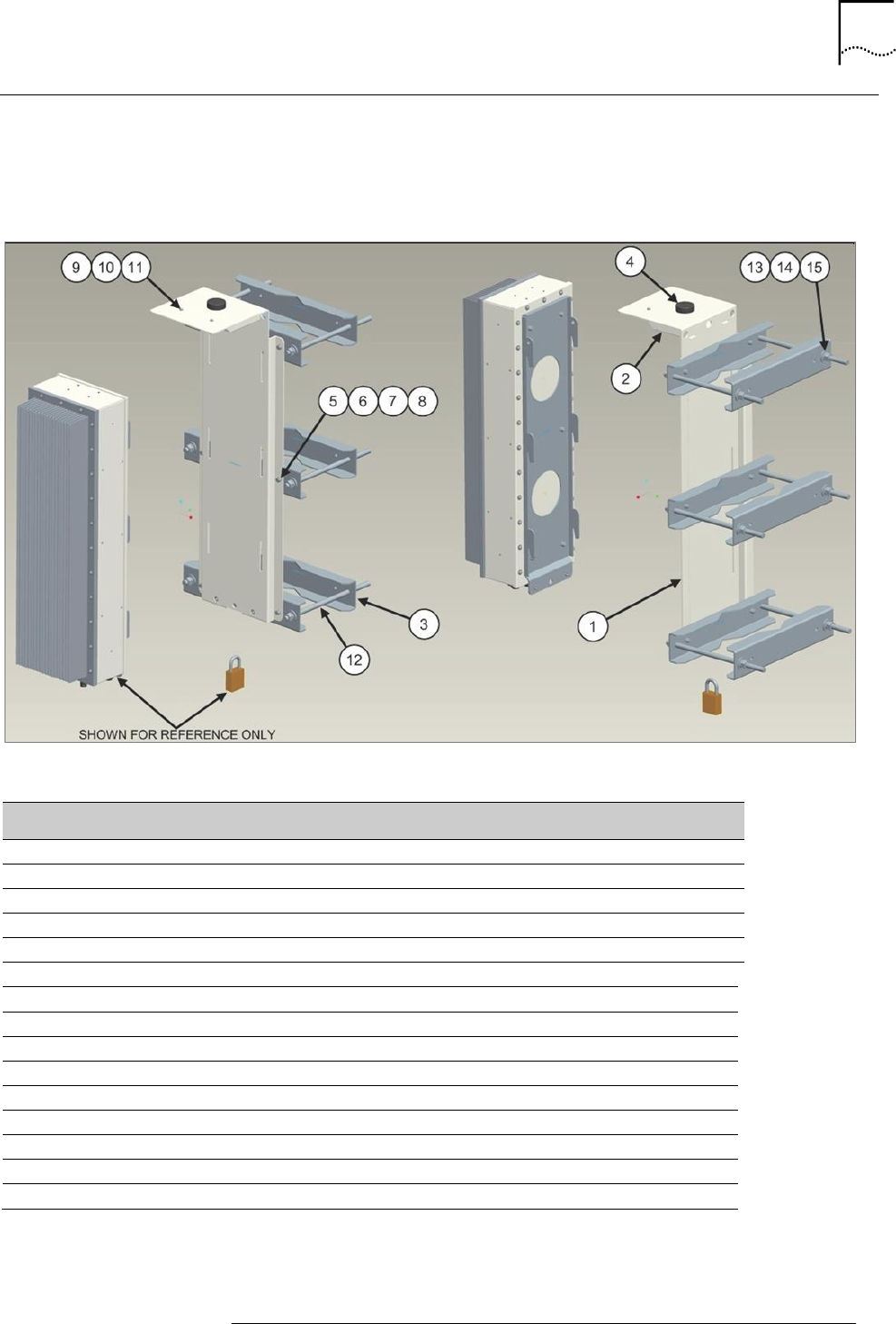
Pole Mounting Instructions
Figure 4 shows the Outdoor Micro accessories required for pole mounting. The component numbers
in Figure 5 refer to the components listed in Table 8.
Figure 5: Outdoor Micro Pole Mounting Kit
Table 8: Outdoor Micro Pole Mounting Kit Description
Index
Description
Quantity
1
Mounting Plate
1
2
Cable Guard
1
3
Pole Mount Bracket
6
4
GPS Active Antenna with RG174 Cable, 1.2m
1
5
Bolt, Hex HD, M6x20
6
6
Nut, Hex, M6
6
7
Washer, Flat, M6
12
8
Washer, Lock, M6
12
9
Screw, Pan HD, Phillips, M4x10
2
10
Washer, Lock, M4
2
11
Washer, Flat, M4
2
12
Threaded Rod, LG, 1/2‐13x18”
3
13
Nut, Hex, 1/2”‐13
12
14
Washer, Flat, 1/2”
12
15
Washer, Lock, 1/2”
12

25
STAR SOLUTIONS CONFIDENTIAL
COMPAC Outdoor Micro IP-RAN GSM Installation and Configuration Guide
Part Number D02713GS Rev A3 | Jan 2016
Pole Mounting the Outdoor Micro
1. Using a metal-cutting hacksaw, adjust the threaded rods (12) to the required length.
Note: The locking washer should always be in between the screw, bolt or
nut and the flat washer.
2. Install the brackets (3) on the mounting plate (1) with the:
Bolt (5)
Two washers (7)
Two washers (8)
Nut (6)
3. Insert the six threaded rods (12) into bracket holes and secure them with the:
Nut (13)
Washer (14)
Washer (15)
4. Lift the mounting plate and bracket assembly to the required height on the pole.
5. Attach the remaining three brackets to the rods using the:
Nut (13)
Washer (14)
Washer (15)
6. Tighten the nuts (13) on the rods to secure the assembly on the pole.
Notes:
Tightening torque for 1/2‐13 nuts on the threaded rods is subjective. Do
not over‐tighten nuts. Over‐tightened the brackets will bend.
Ensure the nuts are tightened evenly on the brackets such that all the
brackets are kept parallel to each other.
7. Mount the Outdoor Micro to the pole mounted assembly by sliding the hooks on the back of
the device into the slots on the mounting panel.
8. Tighten the two screw fasteners on the bottom of the Outdoor Micro to connect the device
to the mounting plate.
9. Connect the GPS antenna cable to the TNC connector on the bottom of the Outdoor Micro.
Note: The GPS antenna cable should pass between the mounting plate and
the brackets attached to the mounting plate.
26
STAR SOLUTIONS CONFIDENTIAL
COMPAC Outdoor Micro IP-RAN GSM Installation and Configuration Guide
Part Number D02713GS Rev A3 | Jan 2016
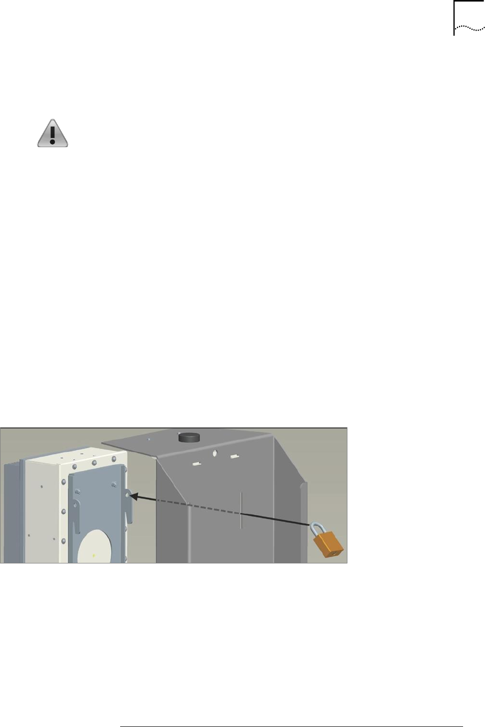
10. Install a padlock through the holes on the bottoms of the Outdoor Micro and mounting plate
so that the Outdoor Micro can only be removed by authorized personnel.
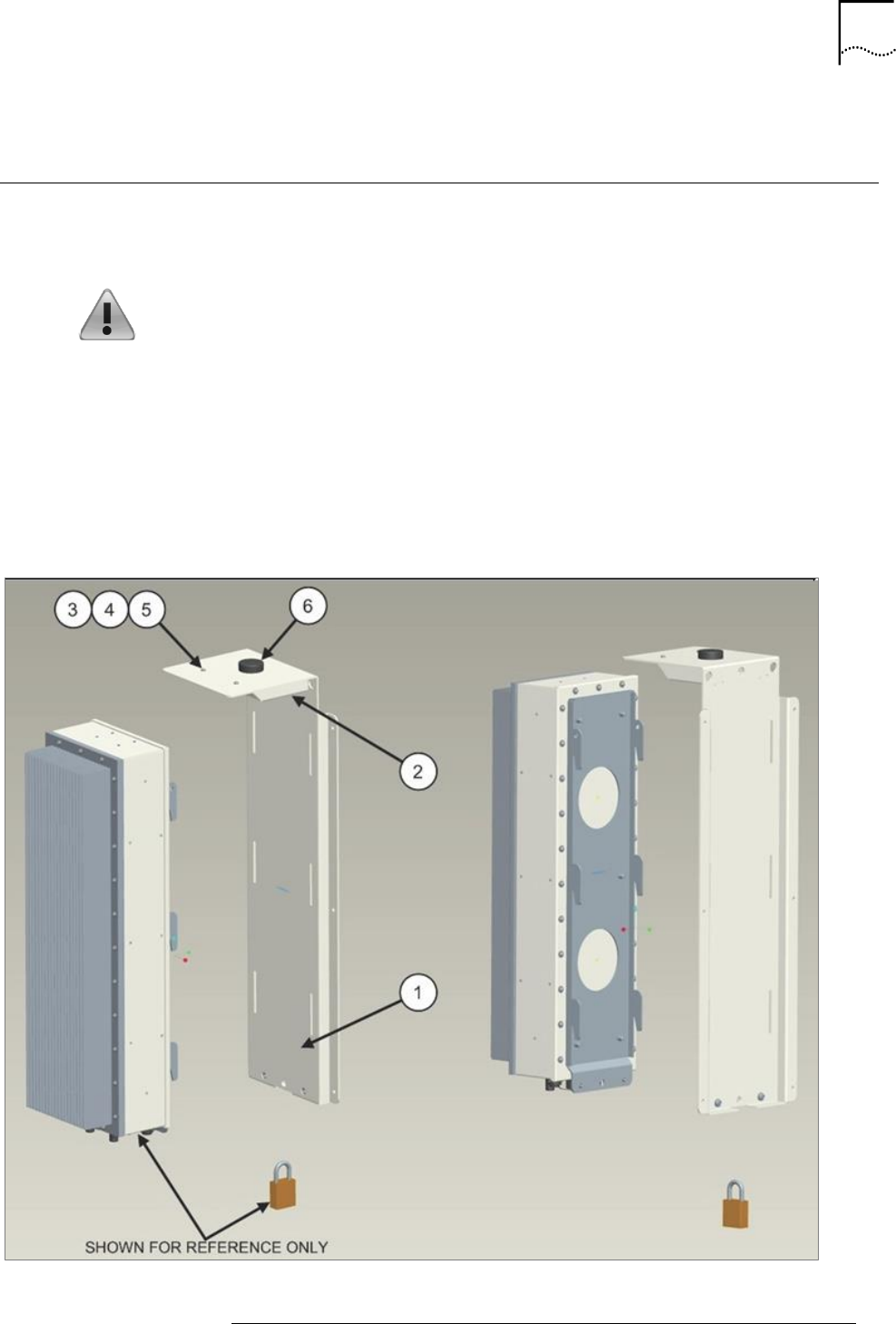
Wall Mounting
Figure 6 shows the Outdoor Micro accessories required for wall‐mounting installation. The
component numbers in Figure 6 refer to the components listed in Table 9.
Warnings:
The wall mounting kit does not contain hardware for connecting the mounting plate to
a wall.
It is the responsibility of the installer to ensure that the mounting location is secure and
that the wall and any other equipment the Outdoor Micro is attached to is able to
support the weight of the Outdoor Micro, and if used, the MCPA.
Failure to securely mount the Outdoor Micro on a sufficiently strong wall could result in
the device falling from the wall, causing possible damage to the device and possible
injury to any persons in its close proximity.
Figure 6: Outdoor Micro Wall Mounting
27
STAR SOLUTIONS CONFIDENTIAL
COMPAC Outdoor Micro IP-RAN GSM Installation and Configuration Guide
Part Number D02713GS Rev A3 | Jan 2016
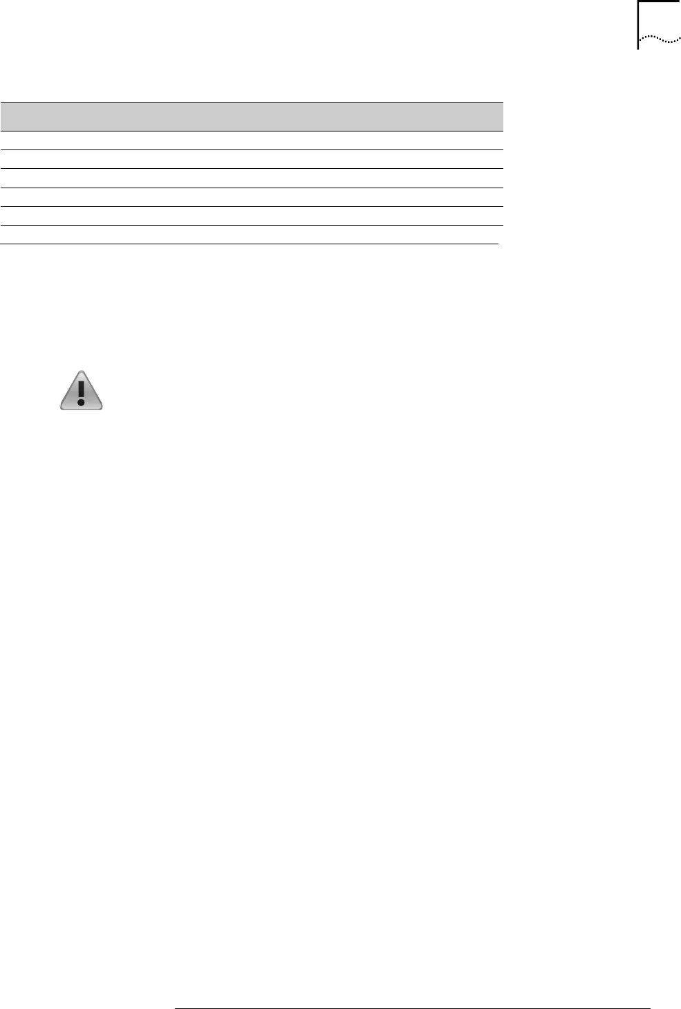
Table 9: Outdoor Micro Wall Mounting Kit Description
Index
Description
Quantity
1
Mounting Plate
1
2
Cable Guard
1
3
Screw, Pan HD, Philips, M4x10
2
4
Washer, Flat, M4
2
5
Washer, Lock, M4
2
6
GPS Active Antenna with RG174 Cable, 1.2m
1
Wall Mounting the Outdoor Micro
1. Determine an appropriate location for mounting the mounting plate (2) on a wall and mark
the location of the six drilling holes using the mounting plate as a template.
2. Drill the six mounting holes.
Note: The locking washer should always be in between the screw, bolt, or
nut and the flat washer.
3. Attach the mounting plate (1) to the wall, taking care to ensure that the GPS cable is
comfortably between the wall and mounting plate.
4. Mount the Outdoor Micro to the wall mounted mounting plate by sliding the hooks on the
device into the slots on the mounting panel.
5. Tighten the two screw fasteners on the bottom of the Outdoor Micro to connect the device
to the mounting plate.
6. Connect the GPS Antenna cable to the TNC connector on the bottom of the Outdoor Micro.
7. Install a padlock through the holes on the bottoms of the Outdoor Micro and mounting plate
to ensure that the Outdoor Micro can only be removed by authorized personnel.
28
STAR SOLUTIONS CONFIDENTIAL
COMPAC Outdoor Micro IP-RAN GSM Installation and Configuration Guide
Part Number D02713GS Rev A3 | Jan 2016
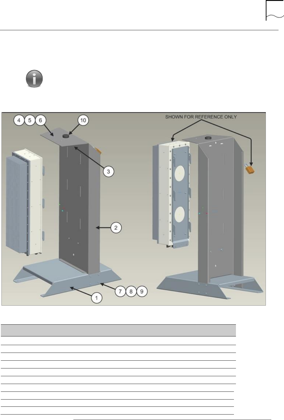
Floor Mounting
Figure 7 shows the Outdoor Micro accessories required for floor‐mounting installation. The floor
mount base provides four holes for securing the mounting assembly to the floor. The component
numbers in Figure 7 refer to the components listed in Table 10.
Note: It is strongly recommended that the mounting assembly be secured
to the floor and that the floor is strong enough to support the weight of both
the base and the Outdoor Micro and, if used, the MCPA.
Figure 7: Outdoor Micro Floor Mounting
Table 10: Outdoor Micro Floor Mounting Kit Description
Index
Description
Quantity
1
Floor Mount Base
1
2
Floor Mount Support
1
3
Cable Guard
1
4
Screw, Pan HD, Philips, M4x10
2
5
Washer, Flat, M4
2
6
Washer, Lock, M4
2
7
Bolt, Hex, M6 x 20
8
8
Washer, Flat, M6
8
9
Washer, Lock, M6
8
10
GPS Active Antenna with RG174 Cable, 1.2m
1
29
STAR SOLUTIONS CONFIDENTIAL
COMPAC Outdoor Micro IP-RAN GSM Installation and Configuration Guide
Part Number D02713GS Rev A3 | Jan 2016
Floor Mounting the Outdoor Micro
1. Determine an appropriate location for the Outdoor Micro.
2. Secure the floor mount base to the floor.
Note: The locking washer should always be in between the screw, bolt, or
nut and the flat washer.
3. The locking washer should always be in between the screw, bolt, or nut and the flat washer.
4. Connect the floor mount support (2) to the floor mount base (1) using the:
Bolt (7)
Washer (8)
Washer (9)
5. Mount the Outdoor Micro to the floor mount assembly by sliding the hooks on the device
into the slots on the floor mount support.
6. Tighten the two screw fasteners on the bottom of the Outdoor Micro to connect the device
to the mounting plate.
7. Connect the GPS Antenna cable to the TNC connector on the bottom of the Outdoor Micro.
8. Figure 8 shows how to install a padlock through the hole in one of the hooks on the device
to ensure that the Outdoor Micro can only be removed by authorized personnel.
Figure 8: Installing a Padlock on a Floor Mounted Outdoor Micro
30
STAR SOLUTIONS CONFIDENTIAL
COMPAC Outdoor Micro IP-RAN GSM Installation and Configuration Guide
Part Number D02713GS Rev A3 | Jan 2016
Mounting the MCPA
The MCPA can be either wall mounted or placed on the rear side of the COMPAC Outdoor Micro floor
mount.
Wall Mounting the MCPA
Warnings:
It is the responsibility of the installer to ensure that the mounting location
is secure and that the wall and any other equipment the MCPA is attached
to is able to support the weight of the MCPA.
Failure to securely mount the MCPA on a sufficiently strong wall could
result in the device falling from the wall, causing possible damage to the
device and possible injury to any persons in its close proximity.
1. Using the MCPA mounting brackets as a template, drill 4 holes in the wall.
2. Install 4 screws into the holes, leaving about 1/8 inch gap between the wall and the screw
heads.
3. Attach the MCPA’s mounting brackets to the screws.
Mounting the MCPA on the Rear of the COMPAC Outdoor Micro Floor Mount
1. Assemble the floor mount bracket as given in Floor Mounting.
2. Install 4 screws into the floor mount holes, leaving about 1/8 inch gap between the mount
and the screw heads.
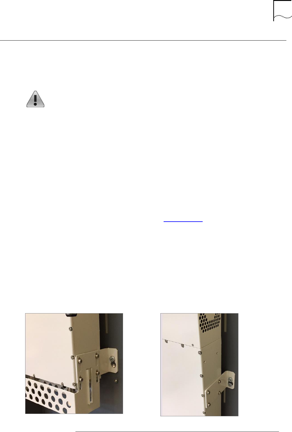
3. Attach the MCPA’s four mounting brackets to the screws as shown in (1) below.
4. Attach four screws to the four mounting brackets as shown in (2) below to secure the MCPA
to the mount.
1: Attaching the MCPA to the
screws
2: Attaching the Second Screw to the
Mounting Bracket
31
STAR SOLUTIONS CONFIDENTIAL
COMPAC Outdoor Micro IP-RAN GSM Installation and Configuration Guide
Part Number D02713GS Rev A3 | Jan 2016
Making the Power Cable
The power cable connector is included with the Outdoor Micro. The power cable must be made by
the device installer or system operator.
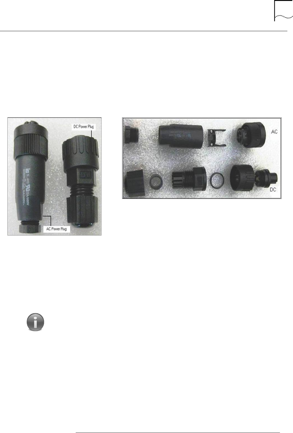
Figure 9 shows one of the provided power connectors that will be provided by Star Solutions based
on if the unit is AC or DC powered.
Figure 9: AC and DC Power Connectors
AC and DC Power Connectors: Side
View
Making AC and DC Power Connectors: From Left to
Right
Making the AC power cable
1. Make sure the power cable is the correct:
Length
Gauge
2. Strip the ends of the cable wires.
Note: The stripped portion of the wire should not be more than 4mm (0.25
inch) in length.
3. Loosen the clip on the cable clamp with a small flathead screwdriver.
4. Feed the cable through the connector body and then through the cable clamp.
5. Loosen the crimp contact screws on crimp contacts 1, 2, and 4.
6. Insert the wires into the crimp contacts and tighten the crimp contact screws. See Table 11
for the proper connections.
32
STAR SOLUTIONS CONFIDENTIAL
COMPAC Outdoor Micro IP-RAN GSM Installation and Configuration Guide
Part Number D02713GS Rev A3 | Jan 2016
Table 11: AC Power Connector Pin Description
AC Power Connector Inside View
AC Power Connector Pin Out
Contact Label Connection
1 Line 1 Live
2 Neutral
3 No Connection
Ground
7. Snap the cable clamp onto the connector end and tighten the clip.
8. Screw the connector body onto the connector head.
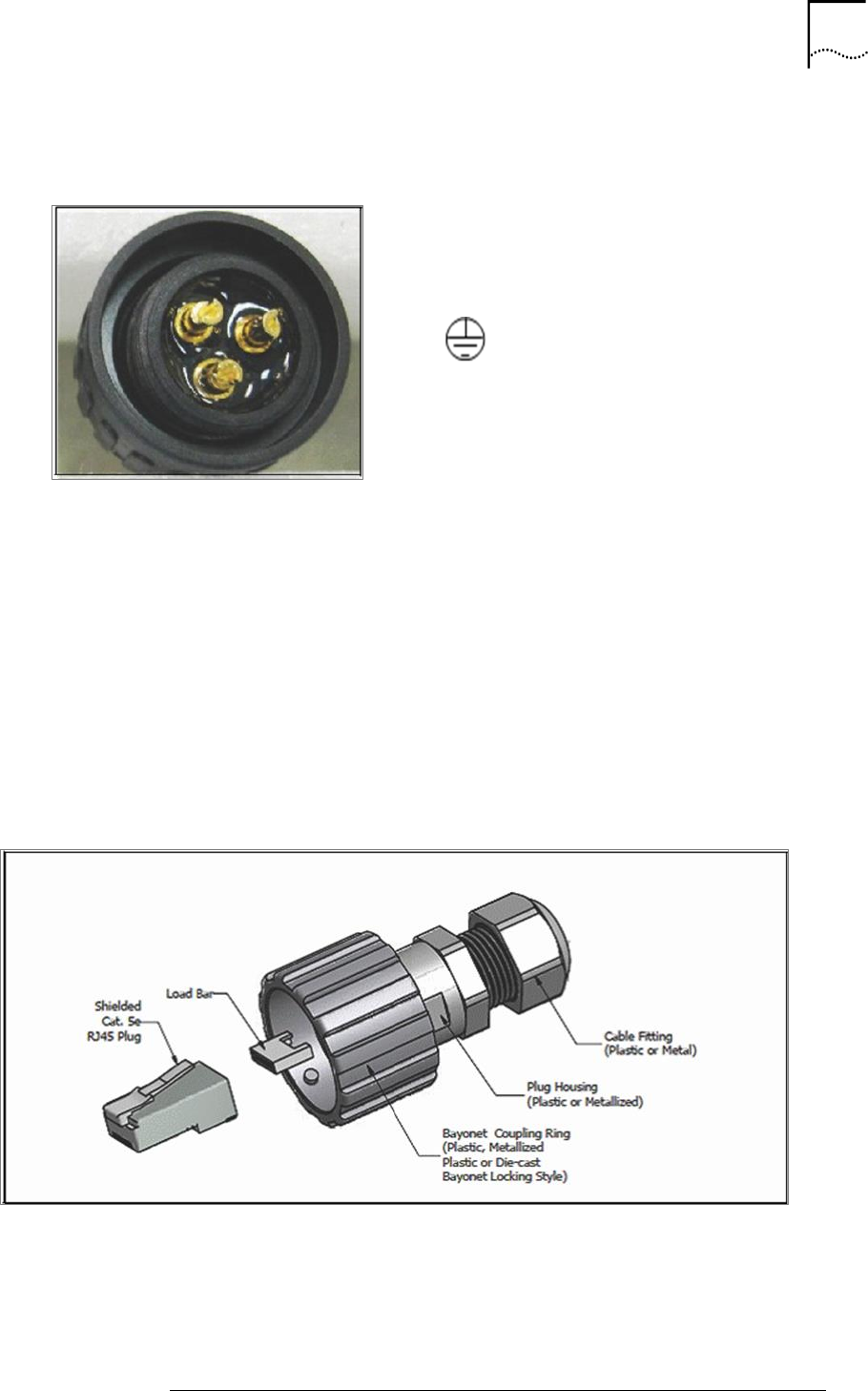
Making the DC Power Cable
1. Feed the cable through the:
Connector end
First rubber washer
Connecter body
Second washer
As shown left to right in Figure 9.
2. Solder the wires on to the gold plated pins contacts 1, 2, and 3. See Table 12 for the proper
connections.
33
STAR SOLUTIONS CONFIDENTIAL
COMPAC Outdoor Micro IP-RAN GSM Installation and Configuration Guide
Part Number D02713GS Rev A3 | Jan 2016
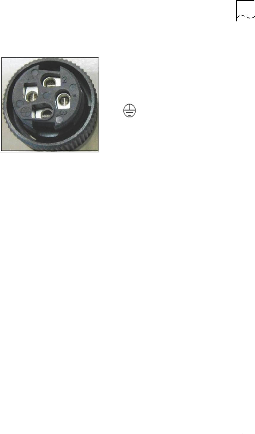
Table 12: DC Power Connector Pin Description
DC Power Connector Inside
View
DC Power Connector Pin Out
Contact Label Connection
1 -48 VDC
2 -48 VDC Return
Ground
3. Pull the cable through the connector body to ensure no slack.
4. Tighten the cable into the connector body to the connector head.
5. Screw the connector body onto the connector end.
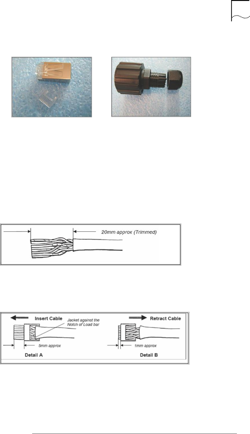
Assembling the Ethernet Cable
A plastic waterproof RJ45 plug kit for the Ethernet cable is included with the Outdoor Micro. The
Ethernet cable must be assembled by the device installer or system operator using this plug kit.
Figure 10 and Figure 11 show the RJ-45 Plug Kit
Figure 10: RJ-45 Plug Components
34
STAR SOLUTIONS CONFIDENTIAL
COMPAC Outdoor Micro IP-RAN GSM Installation and Configuration Guide
Part Number D02713GS Rev A3 | Jan 2016
Figure 11: RJ-45 Plug Assembly
RJ-45 Plug
RJ-45 Plug Assembly
To assemble the RJ45 plug kit:
1. Insert the Ethernet cable into the RJ45 plug housing assembly.
2. Strip the Ethernet cable jacket to approximately 25mm (1 inch).
Ensure the conductor pair is untwisted and aligned side‐by‐side according to EIA/TIA T568A
or T568B.
3. Trim the conductor tips.
Do not remove the insulation from the individual conductors as shown in the drawing below.
4. Insert the wires into the appropriate positions of the load bar and slide the cable to a point
where the cable jacket hits the notch of the load bar.
5. Trim the remaining wire ends to approximately 5mm as shown in Detail A of the drawing
below.
35
STAR SOLUTIONS CONFIDENTIAL
COMPAC Outdoor Micro IP-RAN GSM Installation and Configuration Guide
Part Number D02713GS Rev A3 | Jan 2016
6. Retract the cable, leaving about 1mm length of wire tips as shown in Detail B of the
drawing above.
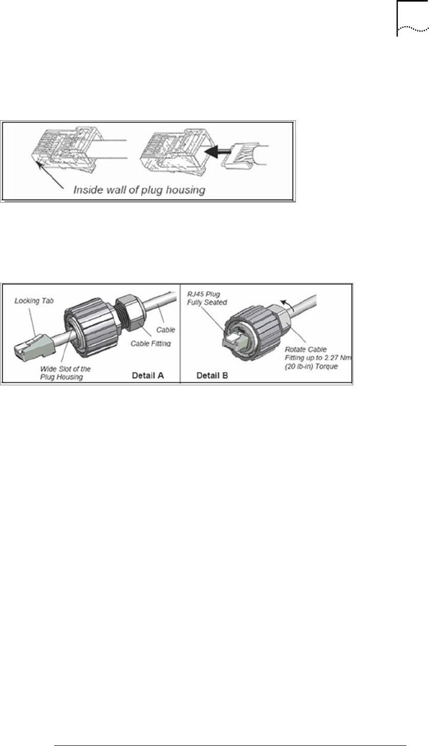
7. Insert the wired load bar into the RJ45 plug until the wire tips are seated against the inside
wall of the plug housing as shown in the drawing below.
8. Terminate the cable and RJ45 plug with a termination tool such as the CONEC 8P8C
modular plug termination tool.
9. Depress the locking tab of the RJ45 plug and align it with the wide slot of the plug housing
as shown in Detail A of the drawing below.
36
STAR SOLUTIONS CONFIDENTIAL
COMPAC Outdoor Micro IP-RAN GSM Installation and Configuration Guide
Part Number D02713GS Rev A3 | Jan 2016
10. Gently pull the cable until the plug is fully seated.
11. Hold the plug in position and rotate the cable fitting until tightened to a torque of 2.27 Nm
(20 lb‐in). See Detail B of the drawing above.
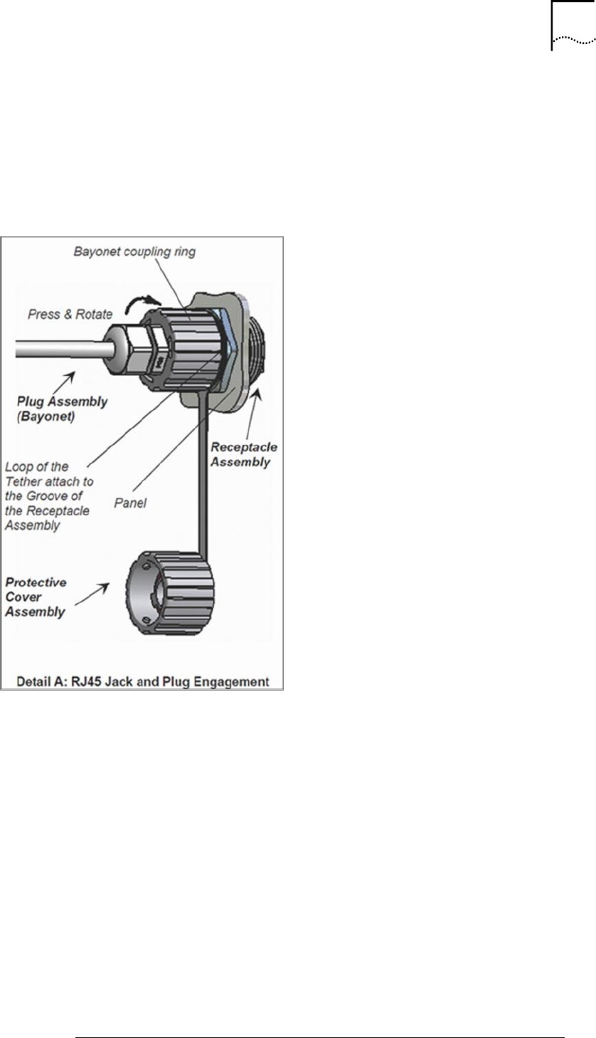
12. To engage the RJ45 jack plug with the receptacle on the COMPAC Outdoor Micro.
13. Align the 3 protrusion keys of the assembled plug / plug housing coupling with the 3
bayonet channels of the receptacle as shown in the drawing below.
14. Press the coupling ring and rotate until the 3 keys click into the bayonet channels.
4. INTERFACE CONNECTIONS
About this chapter
This chapter covers
Grounding
RF Connections
Ethernet Connections
GPS Antenna Connection
Power Connection
Reset Button
Status LED
MCPA Interface Connections
Note: Prior to beginning, verify that the external AC power cable is
disconnected.
Note: All connectors that are not connected must be terminated. The
shielding of all coaxial connections must be grounded.
38
STAR SOLUTIONS CONFIDENTIAL
COMPAC Outdoor Micro IP-RAN GSM Installation and Configuration Guide
Part Number D02713GS Rev A3 | Jan 2016
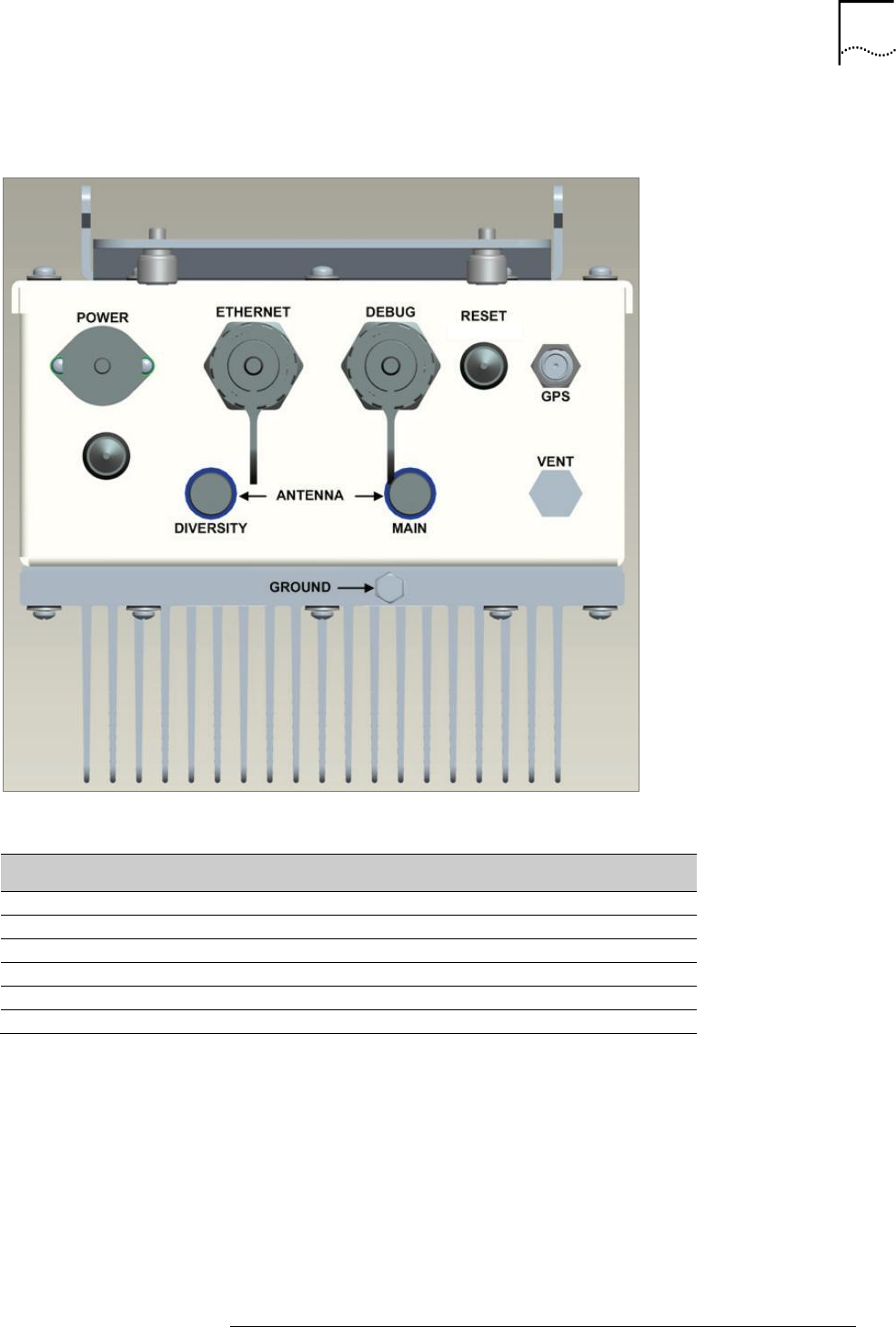
Figure 12 shows the Outdoor Micro’s connection interface
Figure 12: Outdoor Micro Connection Interface
Table 13: Outdoor Micro Interface Connections
Connection
Type
Notes
Power
20-14 AWG
Power Switch
Ethernet
RJ-45
ETH transmission connection
Debug
RJ-45
Debug port
GPS
TNC
Connection from the GPS antenna
Main Antenna
Type N
Main antenna connection (TX/RX)
Diversity Antenna
Not Used
--------------------------
39
STAR SOLUTIONS CONFIDENTIAL
COMPAC Outdoor Micro IP-RAN GSM Installation and Configuration Guide
Part Number D02713GS Rev A3 | Jan 2016
Grounding
The Outdoor Micro is grounded using the ground nut on the bottom of the unit. See Figure 12.
To ground the Outdoor Micro:
1. Loosen the ground nut on the Outdoor Micro.
2. Connect the ground wire to the ground nut and tighten the nut.
Warning: The ground wire should connect to a ground rod or other
grounding source and should be independent of the power cable ground.
RF Connections
The Radio Frequency (RF) cables connect from the Main system antenna to the Main type N antenna
connector on the bottom of the Outdoor Micro. See Figure 12.
The network operator is responsible for mounting and providing lightning protection for the antennas.
Caution: To avoid possible damage to the RF Connectors, do not exceed 4
in‐lbs of torque.
To connect the RF cables:
1. Make sure that the power cable is disconnected.
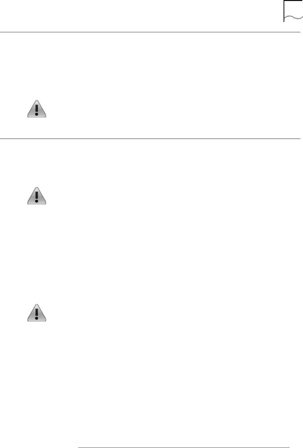
2. Connect the surge arrestor to the main antenna connection prior to the antenna cable as
shown in Figure 13.
3. Connect the main antenna cable to the other end of main surge arrestor.
4. Screw the male type N connector of the main antenna cable into the female type N connector
on the connection interface. The connection should be tightened by hand or, if necessary,
pliers or a torque wrench can be used.
Caution: Weatherproofing material must be installed on the antenna
connection to ensure that the connection is sealed.
40
STAR SOLUTIONS CONFIDENTIAL
COMPAC Outdoor Micro IP-RAN GSM Installation and Configuration Guide
Part Number D02713GS Rev A3 | Jan 2016
Figure 13: RF Antenna Cable Connection Drawing
41
STAR SOLUTIONS CONFIDENTIAL
COMPAC Outdoor Micro IP-RAN GSM Installation and Configuration Guide
Part Number D02713GS Rev A3 | Jan 2016
Ethernet Connections
This section includes:
Ethernet Connection
Debug Connection
Debug and Ethernet cables must be fitted with the Ethernet cable end connectors provided in the
connector kit.
Ethernet Connection
The Ethernet port is used to connect the Outdoor Micro to the network. See Figure 12.
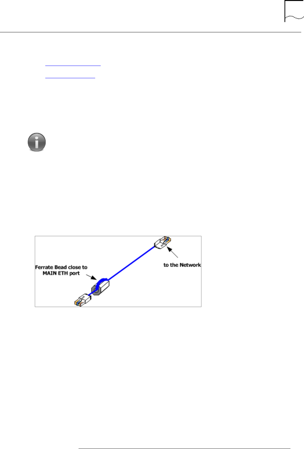
Note: Use the Ferrite Bead on the ETH cable when connecting the Outdoor
Micro to the network.
To connect to the Ethernet port:
1. Remove the termination cap from the Ethernet port.
2. Loop the Ethernet cable around Ferrite Bead, close to one of the plugs, two or three times as
shown in Figure 14.
Figure 14 Ferrite Bead Installation On The Outdoor Micro ETH Cable
3. Connect the Ethernet cable to the Ethernet port.
42
STAR SOLUTIONS CONFIDENTIAL
COMPAC Outdoor Micro IP-RAN GSM Installation and Configuration Guide
Part Number D02713GS Rev A3 | Jan 2016
Debug Connection
The Debug port is used for on‐site troubleshooting and configuration of the Outdoor Micro. See
Figure 12.
Note: Use the Ferrite Bead on the ETH cable when connecting the Outdoor
Micro to the network.
To connect to the debug Ethernet port:
1. Remove the termination cap from the Debug port.
2. Loop the Ethernet cable around Ferrite Bead, close to one of the plugs, two or three times
as shown in Figure 14.
3. Connect the debug cable to the Debug port.
4. When troubleshooting and configuration is complete, remove the debug cable and replace
the termination cap on the Debug port.
Note: The Debug port should only be used to debug the Outdoor Micro. If
any other connections must be made to the Debug port, contact Technical
Support.
Caution: Unsupported connections to the Debug port can cause the
Outdoor Micro to malfunction, resulting in the potential loss of data.
GPS Antenna Connection
The GPS antenna provided comes with a 1.2m long RG174 Cable. If a longer cable is used,
calculations must be done to ensure that the cable length complies with the signal amplification
provided by the antenna.
The GPS antenna is connected by screwing the TNC connector onto the TNC port. See Figure 12.
Note: Weatherproofing material must be installed on the GPS antenna
connection to ensure that the connection is sealed.
43
STAR SOLUTIONS CONFIDENTIAL
COMPAC Outdoor Micro IP-RAN GSM Installation and Configuration Guide
Part Number D02713GS Rev A3 | Jan 2016
Power Connection
The Outdoor Micro has no power switch. It is on whenever it is connected to a power source.
A breaker switch must be installed between the power source and the Outdoor Micro. The selection
and installation of the breaker is the responsibility of the installer or network operator.
Caution: Power connections must be performed by qualified personnel only.
To connect power to the Outdoor Micro:
1. Ensure the breaker switch is installed and turned off.
2. Remove the termination cap from the Power port.
3. Connect the power cable to the power port and tighten the connector cap.
The Outdoor Micro can then be powered on by turning on the breaker.
Reset Button
The reset button is used to reset the Outdoor Micro by pushing it down for one second.
Warning: The reset button should not be pressed during power up. Doing
so can cause the Outdoor Micro to malfunction, resulting in the potential loss
of data.
Status LED
The Outdoor Micro has a single external status LED that displays the state of the unit. This allows for
the user to determine the state of the system before other communication methods, such as an IP
connection, have been established.
Table 14 lists the relationship between the LED behavior and the system status.
Table 14: Status LED Behaviours
LED Behavior
System State
Service Provided
Off
Not powered.
No
Solid Red
Preprovisioned—Indicates connectivity to the core
network and the Outdoor Micro is to be provisioned.
Contact Managed Services.
No
Slow Flashing Red
The Outdoor Micro’s VPN connection is not up. The
LED alternates between Off and Red every second.
No
Fast Flashing Red
The Outdoor Micro has no backhaul (no IP on the
Ethernet connection). The LED alternates between
Off and Red four times a second.
No
Solid Orange
The Outdoor Micro encountered an error contacting
or working with ConfigCenter.
No
Slow Flashing
Between Orange
and Red
The Outdoor Micro’s GPS has no lock. The LED
alternates between Orange and Red every second.
No
44
STAR SOLUTIONS CONFIDENTIAL
COMPAC Outdoor Micro IP-RAN GSM Installation and Configuration Guide
Part Number D02713GS Rev A3 | Jan 2016
Fast Flashing
Between Orange
and Red
The Outdoor Micro’s Auxiliary Interface is down
(CDMA or second TRX, depending on hardware
options). The LED alternates between Orange and
Red four times a second.
No
Solid Green
All waveforms are functioning. Primary GSM TRX, or
primary GSM TRX and CDMA (depending on the
hardware options).
Yes
Slow Flashing
Green
Indicates the Outdoor Micro waveforms are
initializing. It is trying to connect to ConfigCenter,
performing a firmware update, or snapshot
activation. The LED alternates between Off and
Green every second.
Yes
Fast Flashing
Green
One or more waveforms or TRX are not functioning.
The LED alternates between Off and Green four
times a second.
Yes
MCPA Interface Connections
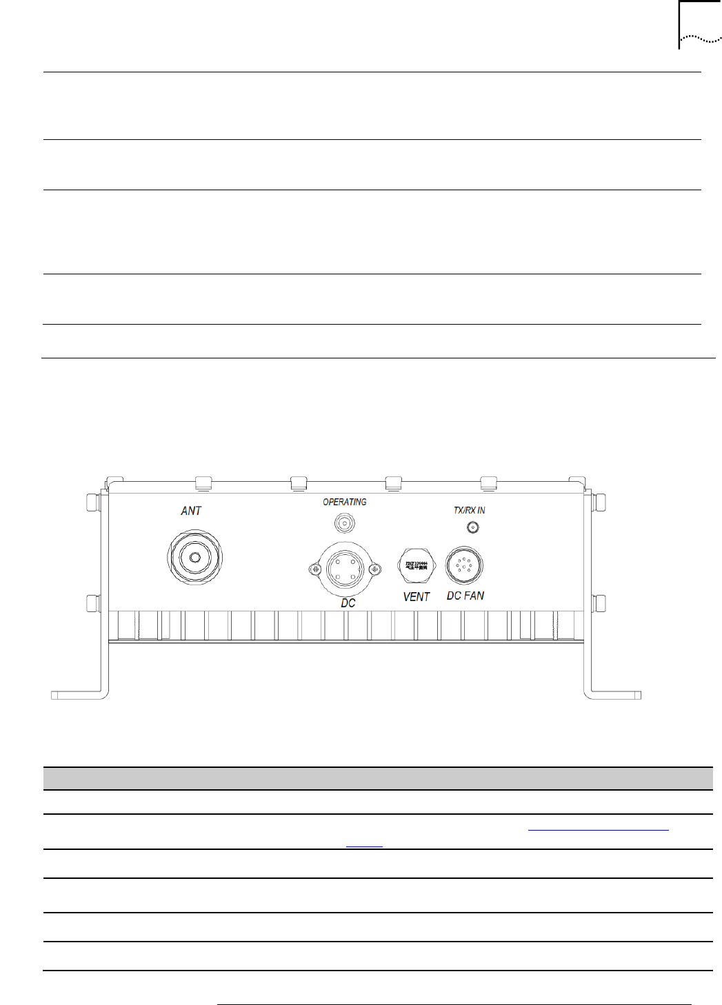
The MCPA’s connectors are located on the bottom of the unit and are shown in Figure 15.
Figure 15: MCPA Connection Interface
Table 15: MCPA Connection Interface Description
Connection
Type
Notes
ANT
DIN Female
RF Antenna connection (TX/RX)
DC
DC Connector
48VDC Power connector (see MCPA Power connector
wiring)
DC_FAN
Power to fans
OPERATING
LED
Green: PA operational
Red: PA with alarm ; interrupted operation
TX/RX_IN
SMA Female
RF input from COMPAC Micro
Serial connector
DIN-9
RS-232 alarm interface (see Figure 16)
45
STAR SOLUTIONS CONFIDENTIAL
COMPAC Outdoor Micro IP-RAN GSM Installation and Configuration Guide
Part Number D02713GS Rev A3 | Jan 2016
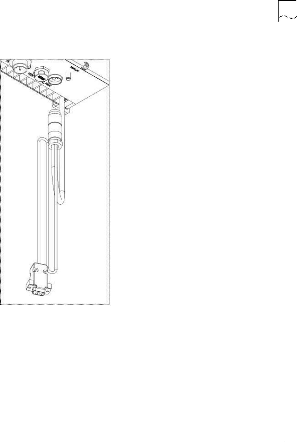
The serial connector is attached as shown in Figure 16.
Figure 16 MCPA Serial Connector Attachment
MCPA Power connector wiring:
Black wire: DC 0V (-48V Return)
White wire: DC -48V
46
STAR SOLUTIONS CONFIDENTIAL
COMPAC Outdoor Micro IP-RAN GSM Installation and Configuration Guide
Part Number D02713GS Rev A3 | Jan 2016
5. OUTDOOR MICRO IP CONFIGURATION
About this Chapter
This chapter provides the information needed to initially configure the Outdoor Micro. It includes:
Outdoor Micro IP Configuration Procedure
Password Management Policy
The Outdoor Micro comes factory-equipped with fixed default parameters. This chapter covers how to
change to addresses that are routable on the operator network.
Table 16 lists the factory-equipped default settings for the Outdoor Micro.
Table 16: Outdoor Micro Default Factory IP Settings
Setting
Value
BTS IP Address
169.254.250.111
Net Mask
XXX.XXX.XXX.XXX
Boothost IP
XXX.XXX.XXX.XXX
Outdoor Micro IP Configuration Procedure
This section includes:
Performing a Default Ping Test
Changing the Outdoor Micro IP Configuration
Performing a Default Ping Test
Before beginning the configuration process, ping each of the network elements in the Outdoor Micro.
Note: The workstation used to configure the Outdoor Micro must be able to
reach the 169.254.250.x network. For individual workstation IP configuration
procedures, see the workstation operating system documentation.
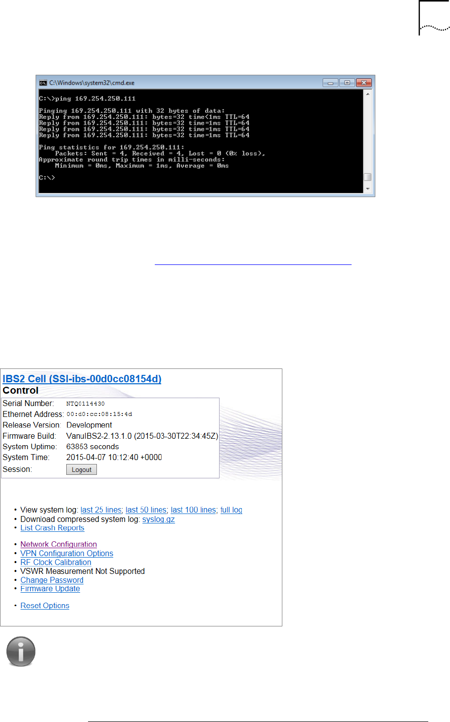
To perform a ping test:
1. From the workstation, launch a command line interface.
2. Ping the BTS by entering: ping 169.254.250.111
A successful ping test appears as shown in Figure 17.
47
STAR SOLUTIONS CONFIDENTIAL
COMPAC Outdoor Micro IP-RAN GSM Installation and Configuration Guide
Part Number D02713GS Rev A3 | Jan 2016
Figure 17: Successful Ping Test
3. If the ping test was:
o Unsuccessful: resolve any connectivity problems and perform the ping test again
until it is successful.
o Successful: go to Changing the Outdoor Micro IP Configuration.
Changing the Outdoor Micro IP Configuration
The default factory settings are changed from the Control Page, a Graphical User Interface (GUI) that
configures the Outdoor Micro from workstations sharing a local network connection. It is shown in
Figure 18.
Figure 18: Outdoor Micro Control Page
Note: The Control Page is compatible only with the Internet Explorer
browser.
To change the Outdoor Micro IP Configuration:
48
STAR SOLUTIONS CONFIDENTIAL
COMPAC Outdoor Micro IP-RAN GSM Installation and Configuration Guide
Part Number D02713GS Rev A3 | Jan 2016
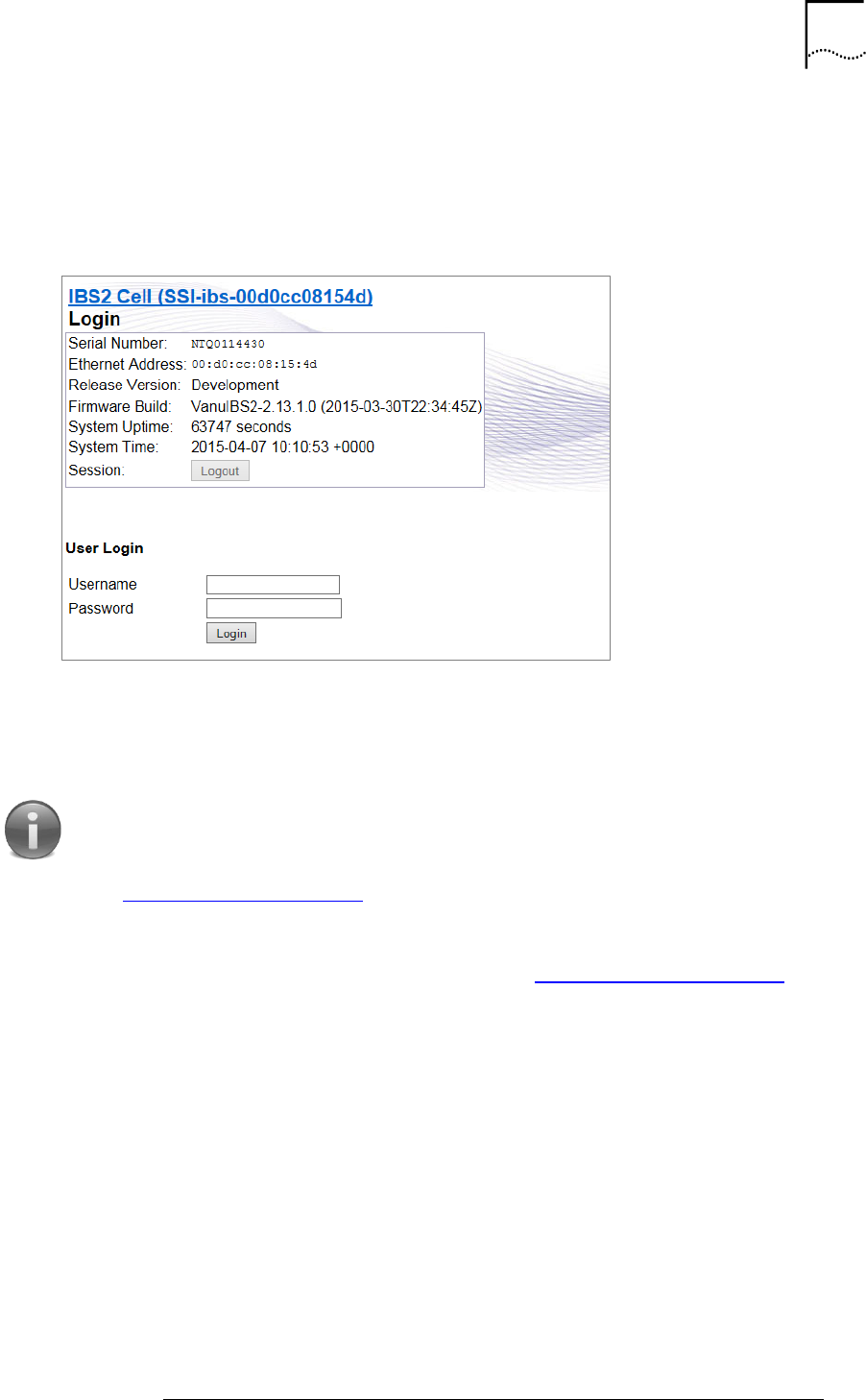
1. Open a web browser.
2. In the web browser’s address bar, enter the BTS IP Address: 192.254.250.111
The log in page appears as shown in Figure 19.
Figure 19: Log In Page
3. Login as <default username><default password>.
Note: If you are logging into the Outdoor Micro for the first time the
default:
Username is admin
Password is admin
See Password Management Policy for more information on passwords.
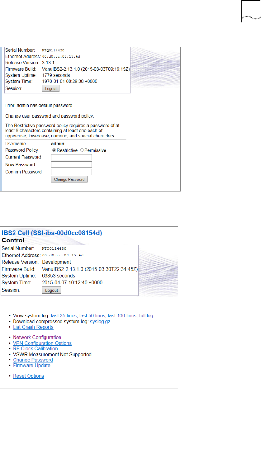
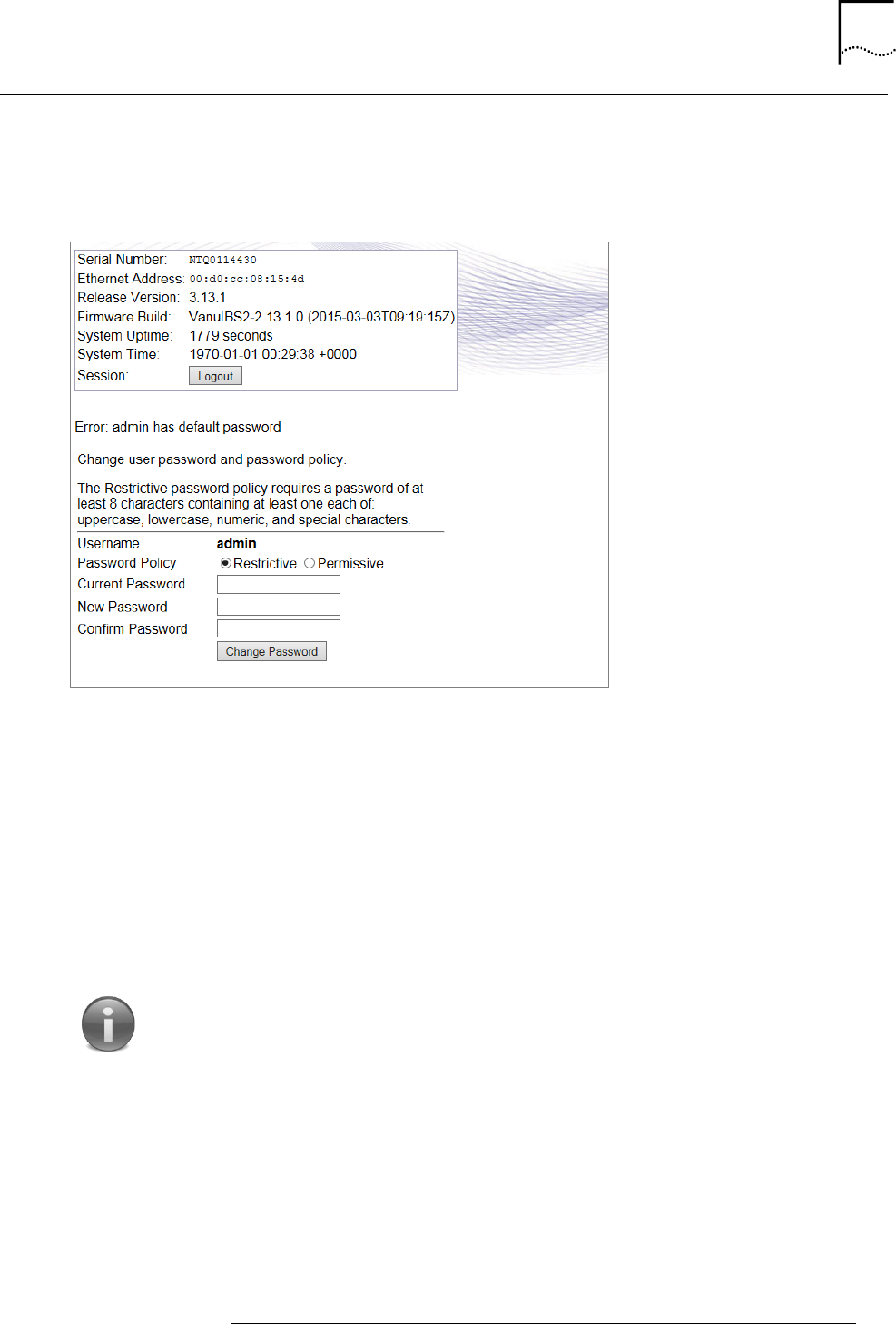
After the very first log into a unit, the screen shown in Figure 20 appears to prompt you to
change the password to one of your choosing. Also see Password Management Policy.
49
STAR SOLUTIONS CONFIDENTIAL
COMPAC Outdoor Micro IP-RAN GSM Installation and Configuration Guide
Part Number D02713GS Rev A3 | Jan 2016
Figure 20: Change Password Screen
After changing the password, the control page reappears as shown in Figure 21.
Figure 21: Control Page
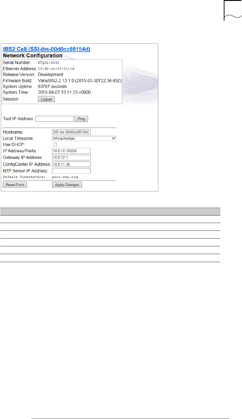
4. On the control page, click Network Configuration.
The Network Configuration page appears as shown in Figure 22.
50
STAR SOLUTIONS CONFIDENTIAL
COMPAC Outdoor Micro IP-RAN GSM Installation and Configuration Guide
Part Number D02713GS Rev A3 | Jan 2016
Figure 22: Network Configuration Page
5. Enter the following information into the control page fields:
Field
Description
Host Name
The host name
Local Time Zone
From the drop down list, select the local time zone
Use DHCP
Select disable DHCP
IP Address/Prefix
The unit’s IP address and prefix
Gateway IP Address
The gateway IP address
ConfigCenter IP Address
The ConfigCenter IP address
6. Click Apply Changes.
7. Disconnect the installer laptop from the Outdoor Micro.
51
STAR SOLUTIONS CONFIDENTIAL
COMPAC Outdoor Micro IP-RAN GSM Installation and Configuration Guide
Part Number D02713GS Rev A3 | Jan 2016
Password Management Policy
The change password screen is shown in Figure 23. You can access it at any time from the main
screen (Figure 18) by clicking Change Password.
Figure 23: Change Password Screen
The following list provides the password requirements. The password must contain the following:
Upper case character (A, B, C, D, etc.)
Lower case character (a, b, c, d, etc.)
Special character (&, %, #, !, etc.)
Numerical character (1, 2, 3, 4, etc.)
At least eight characters long
For example, Star@123 is a valid password.
Notes:
The account locks out for 60 minutes when you enter the wrong password
5 consecutive times.
The last five passwords may not be reused. The password history is
enforced.

A REGULATORY NOTICES
RF Maximum Permissible Exposure (MPE) Exhibit Requirements
FCC Part 1, Section 1.1307 states the following:
Part 22 Subpart H devices are excluded from routine environmental evaluation when the
operating total power level of all channels is less than 1640 Watts EIRP.
Part 24 Subpart E (Broadband PCS) devices are excluded from routine environmental
evaluation when the operating total power level of all channels is less than 3280Watts
EIRP.
No antenna is supplied with this unit. The installer must not exceed the antenna gain limitations
related to total power requirements in order to be excluded from routine environmental
evaluation.
To comply with the Maximum Permissible Exposure (MPE) requirements for general population
that are specified under FCC Part 1 ‐ Section 1.1310 ‐ Table 1, the maximum power density
resulting from the composite Effective Isotopic Radiated Power (EIRP) from the antenna
connected to this equipment must be limited to the maximum permissible exposure as stated
below:
Power density limit for Band Class 0 = f/1500 = 0.58 mW/cm²
Power density limit for Band Class 1 = 1 mW/cm²
This value can be achieved by multiple combinations of RF output, antenna gain, and distance
from the antenna when energized.
The minimum safe distances from a radiating structure in order to be excluded from routine
environmental evaluation are:
For Band Class 0 (TX: 869–894 MHz RX: 824–849 MHz) d (safe distance) = 4.7 m
For Band Class 1 (TX: 1930 1990 MHz RX: 1850 1910 MHz) d (safe distance) = 5.1 m
The MPE is expressed as follows:
Power Density Pd (mW/cm²) = EIRP/[4*Pi*d²]
Where
d = distance from the antenna expressed in cm.
EIRP expressed in mW = 10[TX Power (dBm) + Ant Gain(dBi)]/10
TX Power (dBm) = 10*log[Tx Power (mW)]
As an example with the transmitter running at 5 watts output into an antenna with a gain of 10
dBi, the minimum safe distance from the antenna to ensure exposure would be:
63 cm to remain below 1 mW/cm2 for the 1900 PCS band, and
83 cm to remain below 0.58 mW/cm2 for the 800 Cellular band.
When installing the antenna, the above relationship should be used to ensure the combination of
power, antenna gain, and distance is such that the maximum permissible power density is not
exceeded. Different combinations of output power and antenna gain will result in different
minimum safe distances.