Star Solutions P800-1 iCell CDMA 1X BTS Module - 800 MHz User Manual Pico BTS
Star Solutions International Inc iCell CDMA 1X BTS Module - 800 MHz Pico BTS
manual

MovingMedia 2000 iCell Pico BTS Installation Guide Page 1 of 16
MovingMedia®2000
.
iCell CDMA2000 1X
Pico BTS
BASIC INSTALLATION GUIDE
RELEASE 4.5
DRAFT 0.1
PART NUMBER NXX0306XXX
MovingMedia 2000 iCell Pico BTS Installation Guide Page 2 of 16
Copyright © 2004 UTStarcom Incorporated. All rights reserved.
Copyright © 2004, UTStarcom, Inc. All rights reserved. No part of this documentation may be reproduced in any form or by
any means or used to make any derivative work (such as translation, transformation, or adaptation) without prior written
permission from UTStarcom, Inc.
UTStarcom, Inc. reserves the right to revise this documentation and to make changes in content from time to time without
obligation on the part of UTStarcom, Inc. to provide notification of such revision or change.
UTStarcom, Inc. provides this documentation without warranty of any kind, either implied or expressed, including, but not
limited to, the implied warranties of merchantability and fitness for a particular purpose. UTStarcom may make improvements
or changes in the product(s) and/or the program(s) described in this documentation at any time.
UNITED STATES GOVERNMENT LEGENDS:
If you are a United States government agency, then this documentation and the software described herein are provided to
you subject to the following:
United States Government Legend: All technical data and computer software is commercial in nature and developed solely
at private expense. Software is delivered as Commercial Computer Software as defined in DFARS 252.227-7014 (June
1995) or as a commercial item as defined in FAR 2.101(a) and as such is provided with only such rights as are provided in
UTStarcom's standard commercial license for the Software. Technical data is provided with limited rights only as provided in
DFAR 252.227-7015 (November 1995) or FAR 52.227-14 (June 1987), whichever is applicable. You agree not to remove or
deface any portion of any legend provided on any licensed program or documentation contained in, or delivered to you in
conjunction with, this User Guide.
UTStarcom, the UTStarcom logo and MovingMedia 2000 are registered trademarks of UTStarcom, Inc. and its subsidiaries.
Other brand and product names may be registered trademarks or trademarks of their respective holders.
R e g u la t o r y
This device complies with Part 15 of the FCC Rules. Operation of this device is subject to the following two
conditions: (1) this device may not cause harmful interference, and (2) this device must accept any interference
received including interference that may cause undesired operation.
Where appropriate, the use of the equipment is subject to the following conditions:
CAUTION! Unauthorized modifications or changes not expressly approved by UTStarcom could void compliance with
regulatory rules, and thereby your authority to use this equipment.
WARNING (EMI) - United States FCC Information - This equipment has been tested and found to comply with the
limits pursuant to Part 15 of the FCC Rules. These limits are designed to provide reasonable protection against harmful
interference in an appropriate installation. This equipment generates, uses, and can radiate radio frequency energy and,
if not installed and used in accordance with the instructions, may cause harmful interference to radio communication.
However, there is no guarantee that interference will not occur in a particular installation. If this equipment does cause
harmful interference to radio or television reception, which can be determined by turning the equipment OFF and ON,
the user is encouraged to try to correct the interference by one or more of the following measures:
–Reorient or relocate the receiving antenna.
–Increase the separation between the equipment and receiver.
–Connect the equipment into an outlet on a circuit different from that to which the receiver is connected.
–Consult the dealer or an experienced radio/TV technician
To comply with Maximum Permissible Exposure (MPE) requirements, the maximum composite output from the
antenna cannot exceed 1.26 Watts EIRP and the antenna must be permanently installed in a fixed location that
provides at least 13 cm of separation from all persons.

MovingMedia 2000 iCell Pico BTS Installation Guide Page 3 of 16
1 P RE F A CE
1.1 Objective
This document provides installation and configuration instructions for setting up an iCell-
CDMA2000 1X system. It covers physical installation, software installation for the various
iCell components (sBSC and BTS), configuration, and initial system operation.
1.2 Organization
The major sections of this guide are as follows:
Table 1-1: Organization Table
Chapter Title Description
Chapter 1 Preface Introduction to the Installation Guide.
Chapter 2 iCell System Description Describes the System components
Chapter 3 BTS Physical Installation Provides mechanical installation
and wiring instructions.

MovingMedia 2000 iCell Pico BTS Installation Guide Page 4 of 16
1.3 Reference Documents
The following table summarizes the applicable reference documents.
Table 1-2: Reference Documents
Ref. Title Number
1 iCell CDMA2000 1X Alarms and Statistics
2 iCell CDMA2000 1X Configuration Guide
1.4 Acronyms and Abbreviations
The following table summarizes the acronyms and abbreviations used throughout the
document.
Table 1 -3: Acronyms and Abbreviations
1PPS One Pulse Per Second
AAA Authentication, Authorization, and Accounting function
Abis Protocol interface between sBSC and BTS
ASN.1 The language used to define the MIB of the NE
EM Element Manager
GPS Global Positioning System
HLR Home Location Register
sBSC iCell Base Station Controller
BTS iCell Base Station Transceiver Subsystem
iMB iCell Main Board
IOS Inter-Operability Standard; A-Interface between sBSC and MSC
IP Internet Protocol
iPA iCell Power Amplifier
MIB Management Information Base
MS Mobile Station (phone)
MSC Mobile Switching Center
NE Network Element or agent
NOC Network Operations Center
OID Object Identifier
OMC Operations & Maintenance Center
PA Power Amplifier

MovingMedia 2000 iCell Pico BTS Installation
Guide Page 5 of 16
PDSN
PSTN
RF
SMSC
SNMP
SNTP
TBD
TCP
TOD
Packet Data Serving Node
Public Switch Telephone Network
Radio Frequency
Short Message Service Center
Simple Network Management Protocol
Simple Network Timing Protocol To Be
Defined
Transmission Control Protocol
Time Of Day
MovingMedia 2000 iCell Pico BTS Installation Guide Page 6 of 16
2 iCell SYSTEM DESCRIPTION
This chapter provides an iCell system description.
2.1 Introduction
The iCell is an IP-based solution for CDMA2000 1X radio access networks.
The iCell system provides the overall functionality of a CDMA2000 1X Base station
transceiver subsystem (BTS) and soft base station controller (sBSC), providing an IP
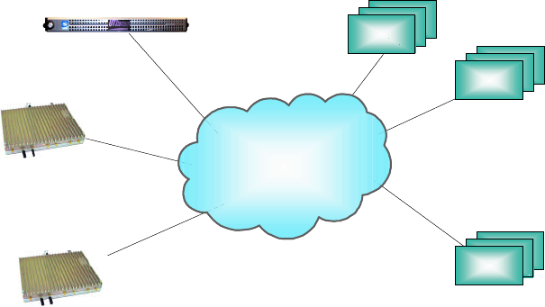
over Ethernet interface to the core network. Figure 2-1 shows the system architecture.
Figure 2-1: iCell System Block Diagram
sBSC
Managed
IP
Network
MSC
IMG
Pico BTS
PDSN
sBSC
Managed
IP
Network
MSCMSC
IMGIMG
Pico BTS
PDSNPDSN
MovingMedia 2000 iCell Pico BTS Installation Guide Page 7 of 16
2.2 System Components
The main iCell system network components are explained in this section.
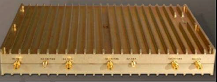
2.2.1 BTS
The BTS is the iCell Base Station Transceiver Subsystem. There can be several BTS units
per sBSC.
The BTS is the radio transmitter/receiver that maintains communication with Mobile
phones. It can be configured as Omni, two sectors or 3 sectors.
The BTS is connected through a Fast Ethernet Switch to the sBSC.
Normally in an enterprise installation, the first BTS unit is connected to the GPS receiver
and serves as an SNTP server for the sBSC and the other BTS units served by the
sBSC. This BTS distributes the TOD protocol messages to other BTS units. The SNTP
server on the first BTS is defined by an IP address. Each additional BTS unit served by
the sBSC is configured to refer to the IP address of the SNTP server.
For single isolated Pico installation where GPS synchronization for handoff is not
required, there is also an option to use an external SNTP server for correct TOD
eliminating the need to install a GPS unit. (see Figure 2.3)
2.2.2 sBSC
The sBSC has the following features:
�The sBSC is the iCell Soft Base Station Controller which can
support several BTS units
�The sBSC must be identified by the MSC
�The sBSC is configured to refer to the IP address of the SNTP server
2.2.3 Global Positioning System (GPS)
The following GPS-produced signals are used for each BTS when Soft or Hard Handoff
is a requirement:
�Time Of Day (TOD) message
�Synchronized 1 PPS
MovingMedia 2000 iCell Pico BTS Installation Guide Page 8 of 16
2.2.3.1 Direct GPS and Daisy Chain of 1 PPS source
For in-building installations, the GPS receiver is connected to one BTS (the first BTS)
in each cluster, directly through the 1 PPS IN SMA connector and the RS232 TOD
port. The 1PPS signal can be extended via coax to other nearby BTS units using the
“1PPS OUT” port of the first BTS going to the 1 PPS IN port of the next BTS.
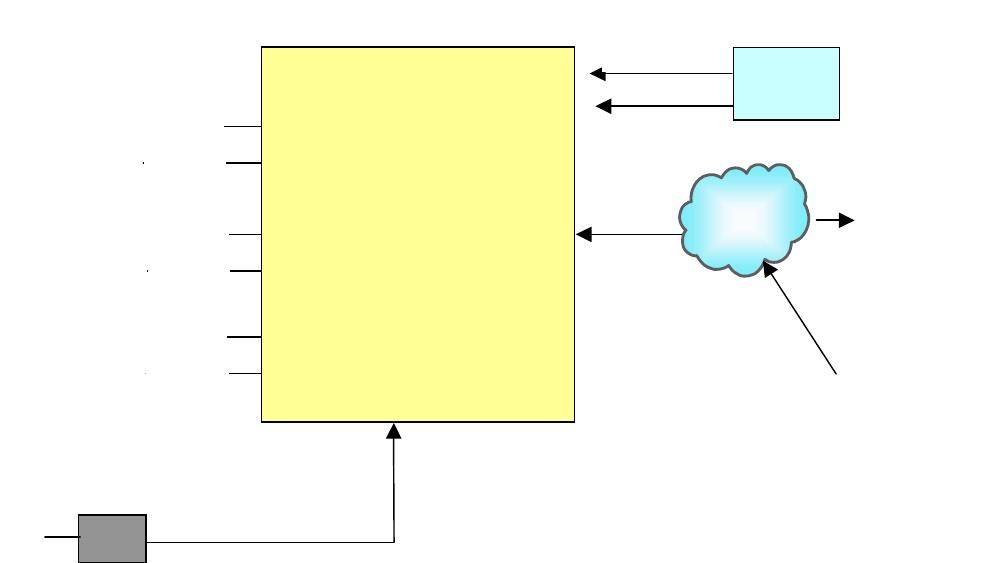
Figure 2-3: Optional GPS Signals
5.2V
DC
IP
BSC
Server
Tx/Rx
Rx dv
S
ector 1
Tx/Rx
Rx dv
Sector 2
Tx/Rx
Rx dv
Sector 3
IP
Network
External
SNTP Server
for TOD if
GPS not
installed
GPS
Receiver
1 PPS
TOD
Optional
BTS
110-220 VAC
MovingMedia 2000 iCell Pico BTS Installation Guide Page 9 of 16
2.2.4 Simple Network Time Protocol (SNTP) Server
The SNTP server provides client and server services to obtain and set accurate date
and time in network-connected devices. It operates in three selectable modes:
�Unicast:
A client sends a request to a designated time server at its
unicast address and receives a response from which it
determines the time.
�Multicast:
A time server periodically sends a message containing the
current time to a designated multicast group address. The
client listens on this multicast address.
�Anycast:
A client sends a request to a designated local broadcast
address or multicast group address. One or more time servers
reply with their own unicast address and the client binds to the
first one it receives. The client continues operation in unicast
mode.

MovingMedia 2000 iCell Pico BTS Installation Guide Page 10 of 16
3 BTS PHYSICAL INSTALLATION
3.1 General
This chapter provides physical installation and wiring instructions for the BTS.
3.2 Unpacking
Upon receipt of, and before opening the iCell packages, inspect for any damage that
might have occurred during shipping. If the package shows any signs of external
damage or rough handling, notify your carrier's representative.
CAUTION
All modules are susceptible to electrostatic discharge (ESD) even while
installed. Take the necessary precautions to minimize electrostatic damage
while handling modules.
Carefully remove all parts and hardware out of the
packages. Carry out a full inventory before installation
procedure starts.
3.2.1 BTS 19" Rack Mount Packing List
The iCell 19" Rack Mount package includes the following:
1. 1U 19” Chassis complete with AC or DC power supply
2. Optional GPS Unit (Mandatory when CDMA Handoff is required)
1
MovingMedia 2000 iCell Pico BTS Installation Guide Page 11 of 16
3.2.2 BTS Wall Mount Packing list
The iCell wall mount package includes the following:
1. Pico BTS complete with cover
2. AC adapter unit
3. Wall Mounting bracket
4. Optional GPS unit (Mandatory when CDMA Handoff is required)
3.3 Mounting Instructions
The section provides instructions for the following:
�19" rack mounting
�Wall mounting
3.3.1 BTS 19" Rack Mount
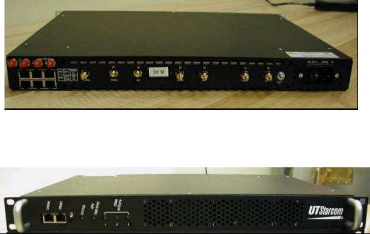
See Figure 3-1 and Figure 3-2.
1. Insert the BTS 1X 19" unit into a 19" rack. Secure with four NF10 screws.
2. Connect BTS 19" Rack Mount according to paragraph 3.4.2.
Figure 3-1: BTS 19' Rack Mont Rear View
Figure 3.2: BTS 19” Rack Mount Front View
MovingMedia 2000 iCell Pico BTS Installation Guide Page 12 of 16
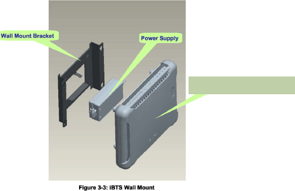
3.3.2 BTS Wall Mount
See Figure 3-3.
BTS Wall Mount
MovingMedia 2000 iCell Pico BTS Installation Guide Page 13 of 16
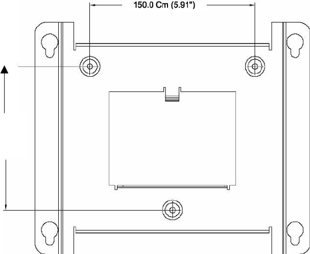
Perform the wall mounting. Mark the location of the drilling holes according to Figure
3-4. Drill three holes
Hang the Mounting Bracket in the marked location and fasten with three screws.
Mount the Power Supply onto the Wall Mount Bracket. Assemble the iCell unit to the
bracket on the spacers. Connect a BTS module according to section 3.4.2.
Figure 3-4: Hole Location for Mounting Bracket
To comply with Maximum Permissible Exposure (MPE) requirements, the maximum composite
EIRP output from the antenna cannot exceed 1.26 Watts EIRP and the antenna must be
permanently installed in a fixed location that provides at least 13 cm of separation from all persons.
This is maximum separation based on the possibility of connecting the Pico to a very high gain
directional antenna of 11 dBi. A more typical 3 dBi gain antenna would result in a separation
distance of 5 cm.
3.4 Interface Connections
3.4.1 BTS Interface Connections
Verify that the power switch is off and the external AC power line is
disconnected.
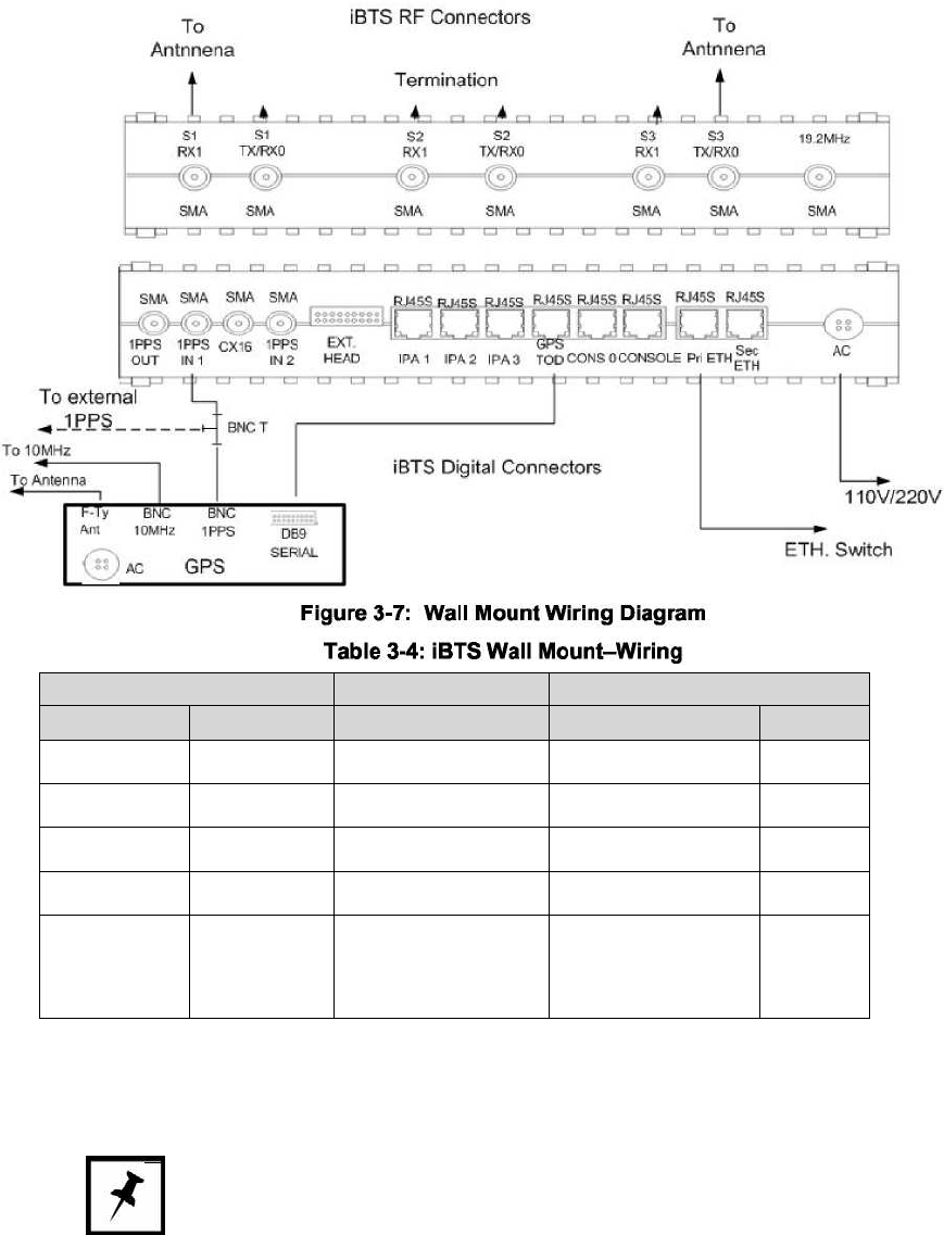
3.4.2 BTS Interface Connection
Figure 3-7 illustrates the wiring diagram of the wall mount configuration and Table 3-4
provides the wiring parameters.
130.0 cm (5.12")
MovingMedia 2000 iCell Pico BTS Installation Guide Page 14 of 16
MovingMedia 2000 iCell Pico BTS Installation Guide Page 15 of 16
BTS MCN Destination
Name Type Name Type
Pri Eth RJ45S Standard CAT5 Ethernet Switch RJ45S
GPS TOD RJ45S 45-89332-M3 GPS DB9
Console RJ45S 45-89330-M3 PC DB9
1 PPS IN 1 SMA TBD GPS 1 PPS BNC
Power
Supply
Switching AC Power
363-02155-0002
or
363-06097-0015
External Source
Power
NOTE All SMA connectors that are not connected should be terminated.
MovingMedia 2000 iCell Pico BTS Installation Guide Page 16 of 16
3.4.2.1 Connecting to GPS
To Connect GPS:
Connect the GPS receiver ANT F-Type connector the GPS antenna cable.
Connect the GPS receiver SERIAL DB9 connector the BTS GPS
TOD connector with cable MCN 45-89332.
Connect the BNC T receiver adaptor (female) to the BTS 1 PPS IN
SMA connector with cable MCN 45-89800-1.
3.4.2.2 Miscellaneous Connections
To connect the remainder connections:
Connect BTS Primary Ethernet port through Internet switch to BTS.
Connect BTS S1 Tx/RX1 to external antenna
or to DAS for typical omni configuration.
Rx diversity is not normally required for Pico
in-building deployments.
All unused SMA connectors should be terminated.
For wall mount Pico, connect 4 pin DIN cable from AC adapter output to
BTS 5.2VDC input and connect AC adapter to 110 or 220 V AC supply
For AC Rack mount version, just connect the AC cord to 110 or 220 V AC
supply.
For DC Rack Mount version, make sure the main rack breaker is off and the
BTS power switch is in the off position. Connect the –48v wire as indicated
on the rear of the unit marked “–“ or “–48v” and the positive (Bat. Rtn) wire
to the terminal marked “+” or Bat Return.
The BTS unit is now ready for configuration and testing.