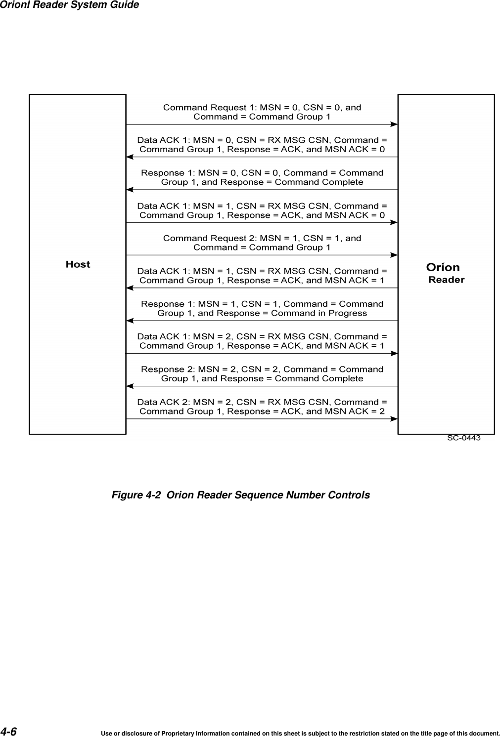
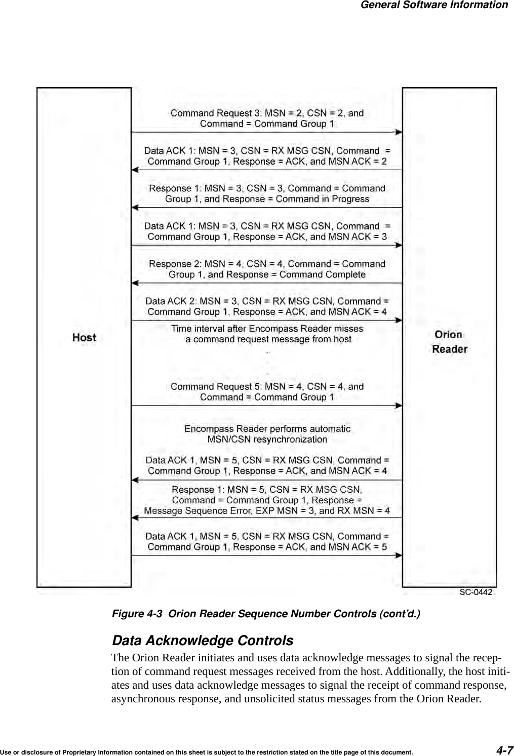
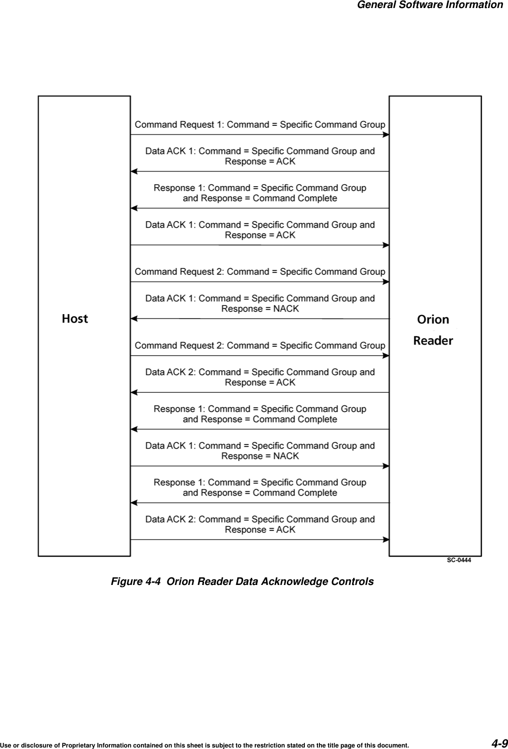
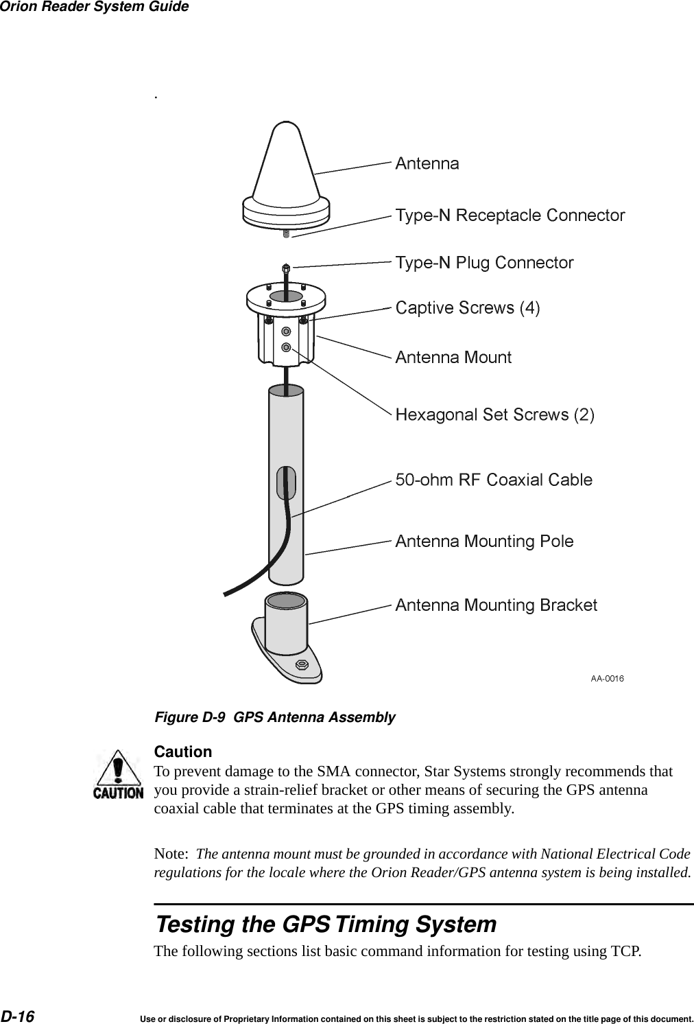
Star Systems ORION Location & Monitoring Transmitter User Manual
Star Systems International Limited Location & Monitoring Transmitter
UserManual.wiki
>
Star Systems
>
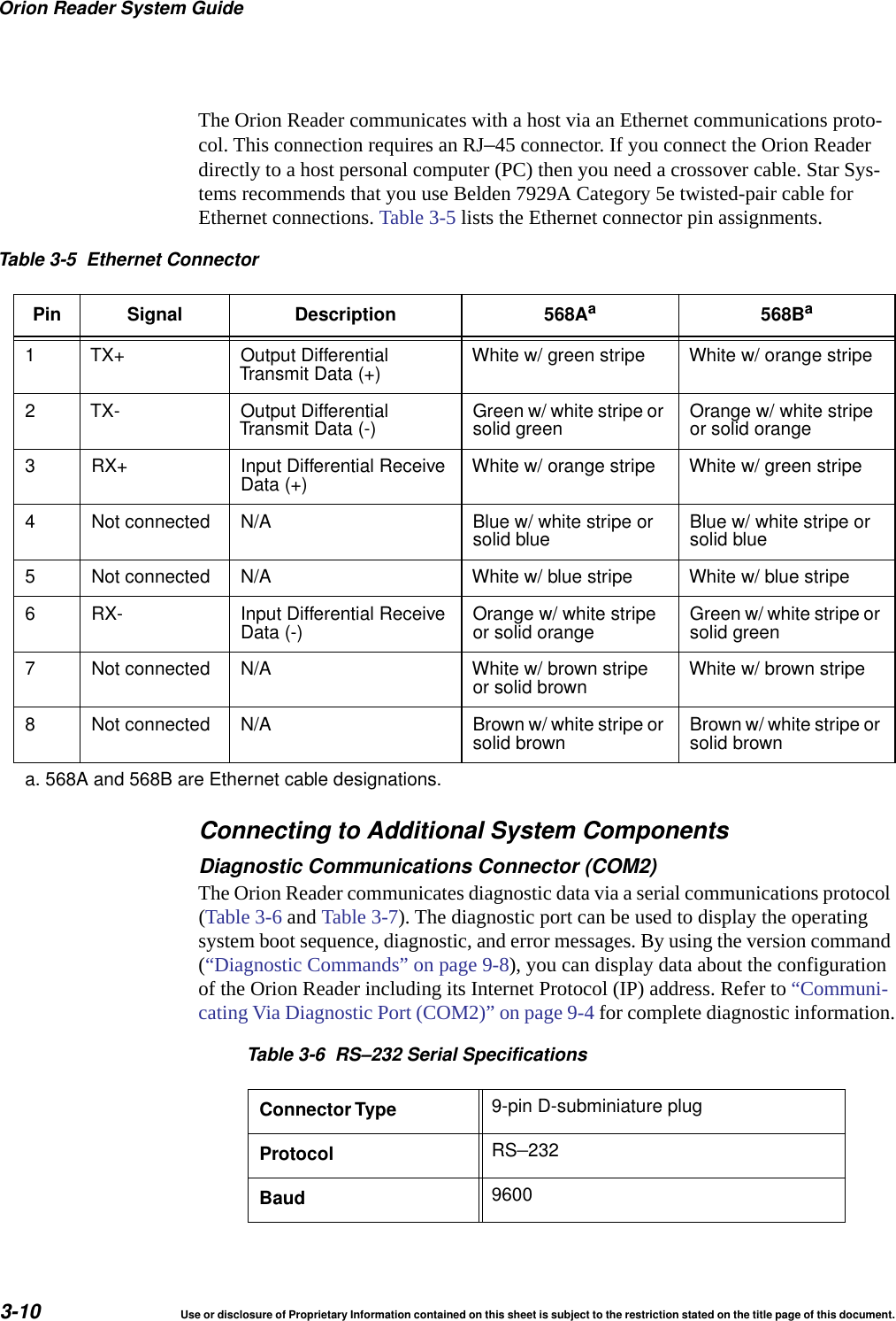
ORION User Manual
Users Manual
Navigation menu
Upload a User Manual
Namespaces
Wiki Guide
HTML
PDF
Info
Views
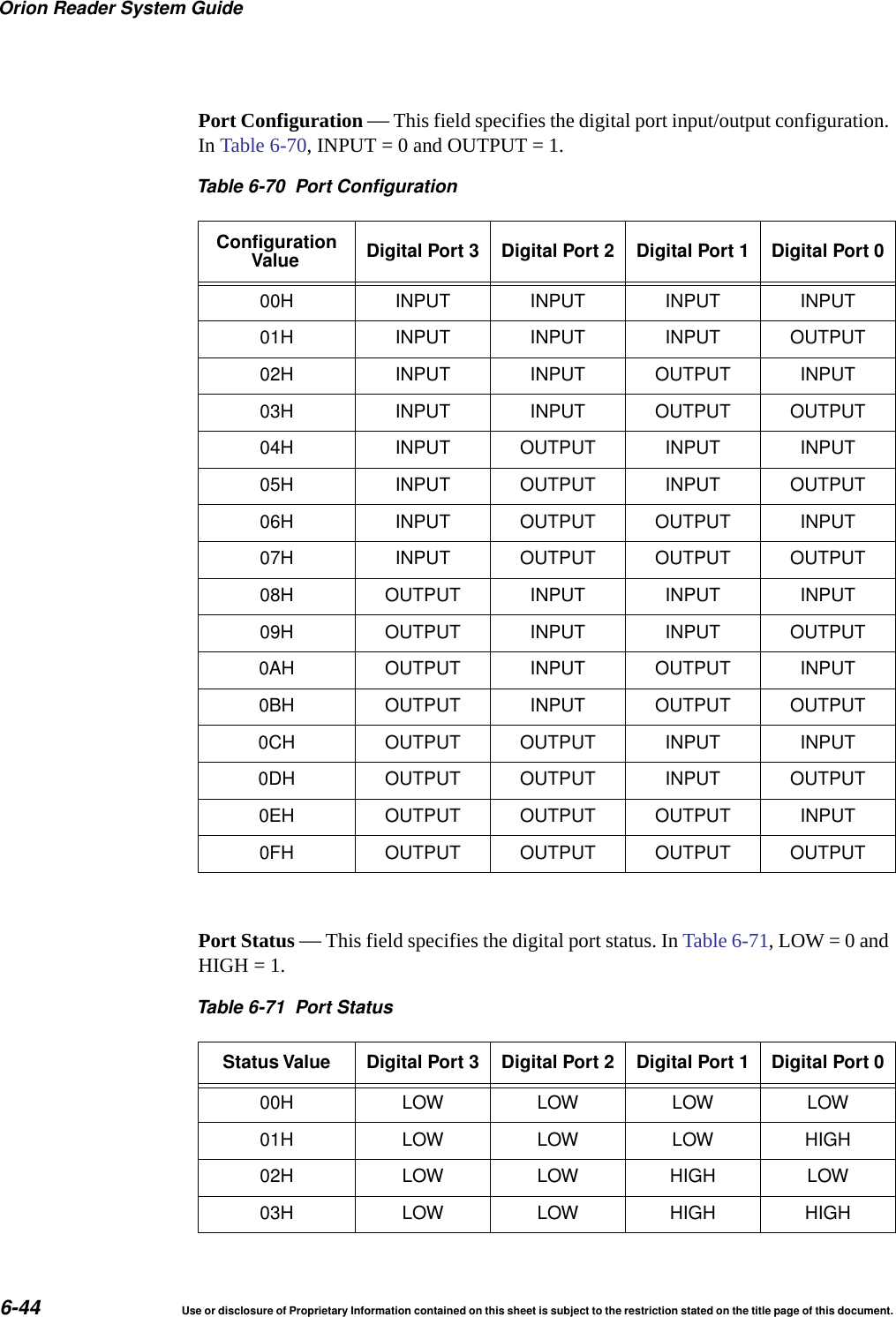
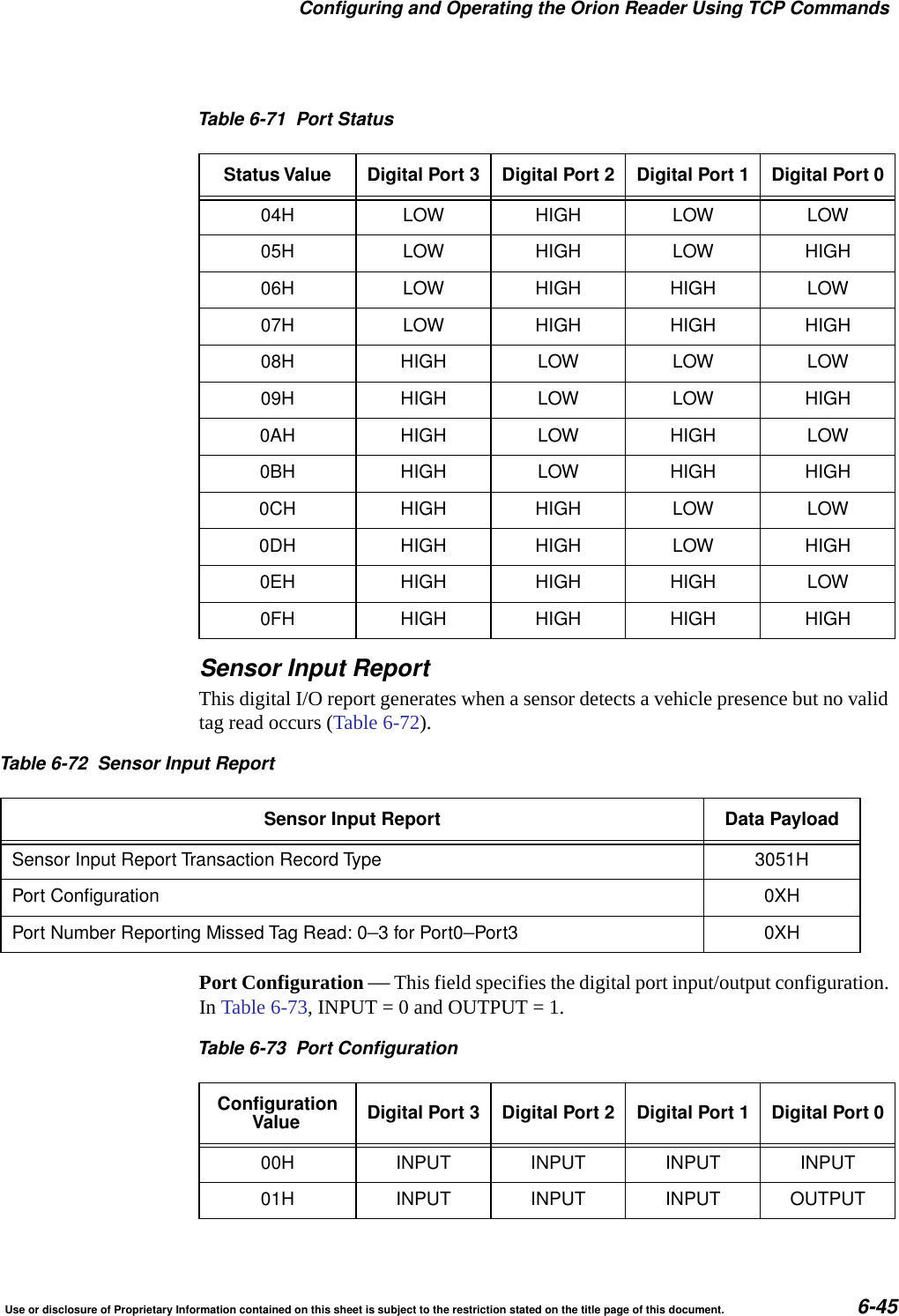
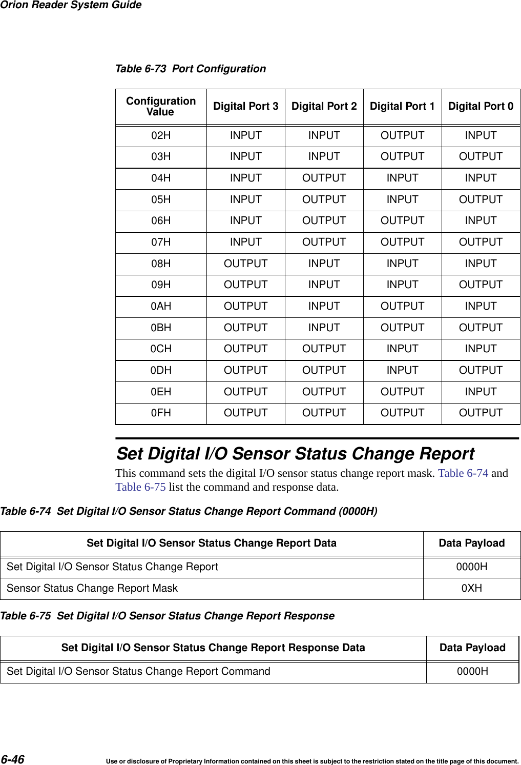
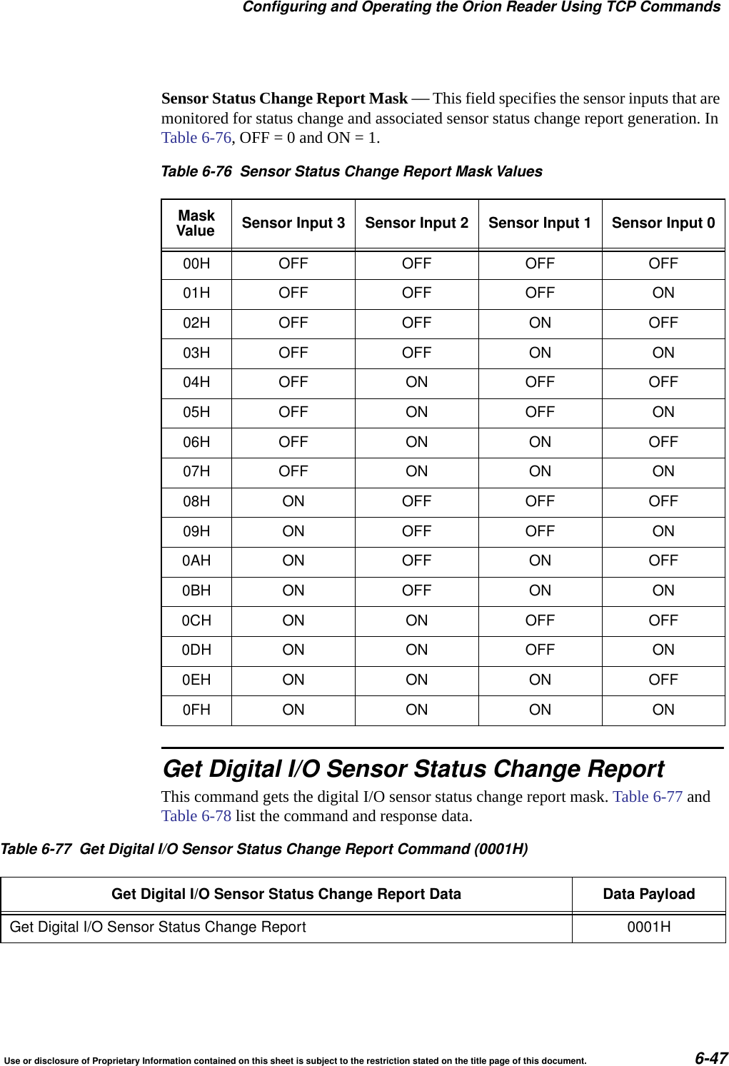
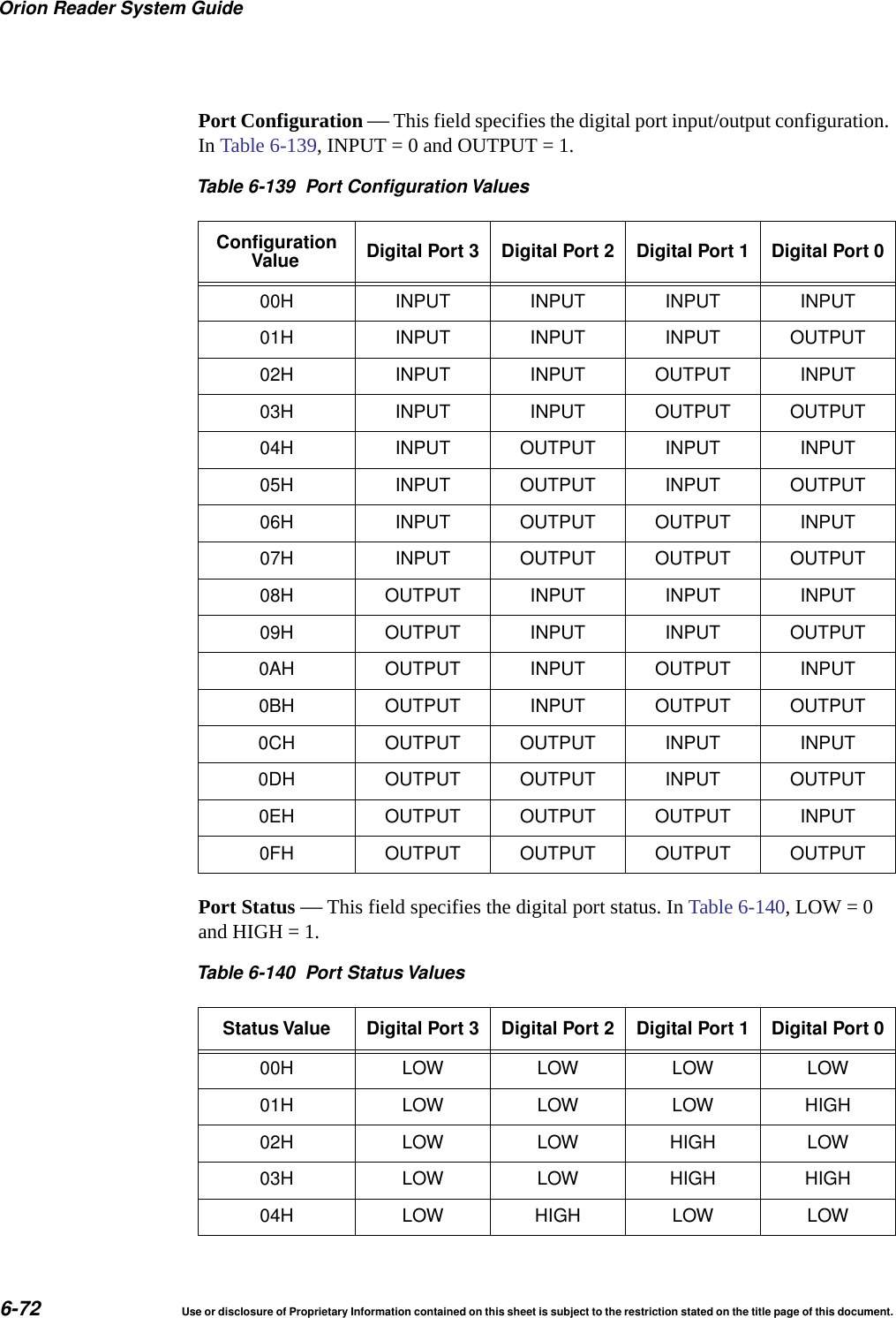
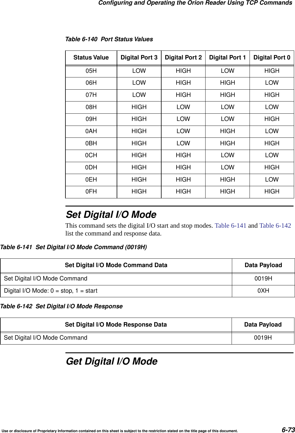
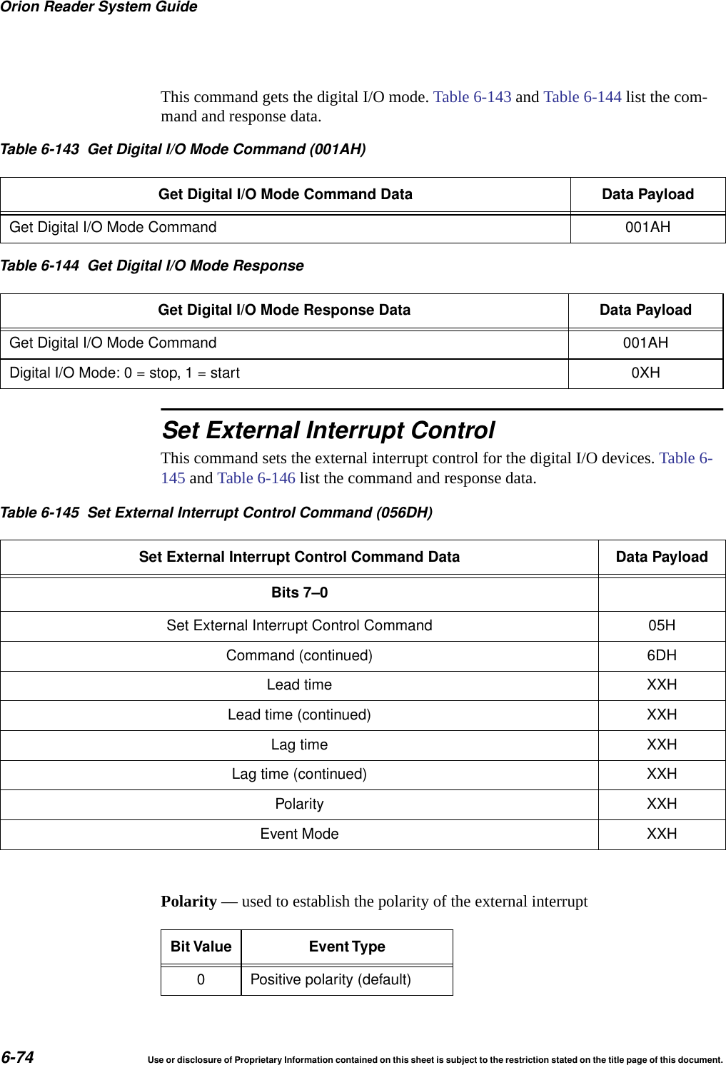
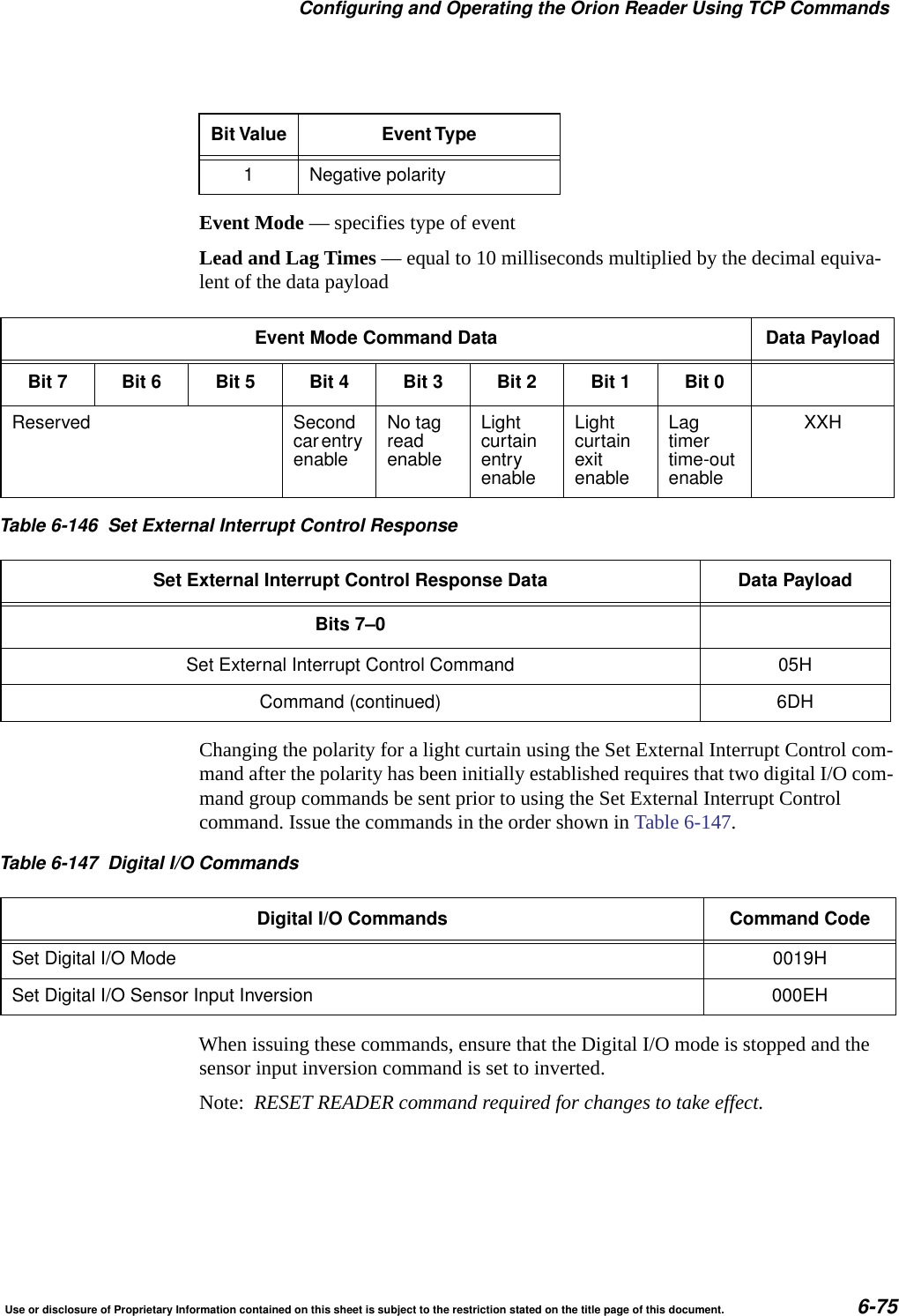
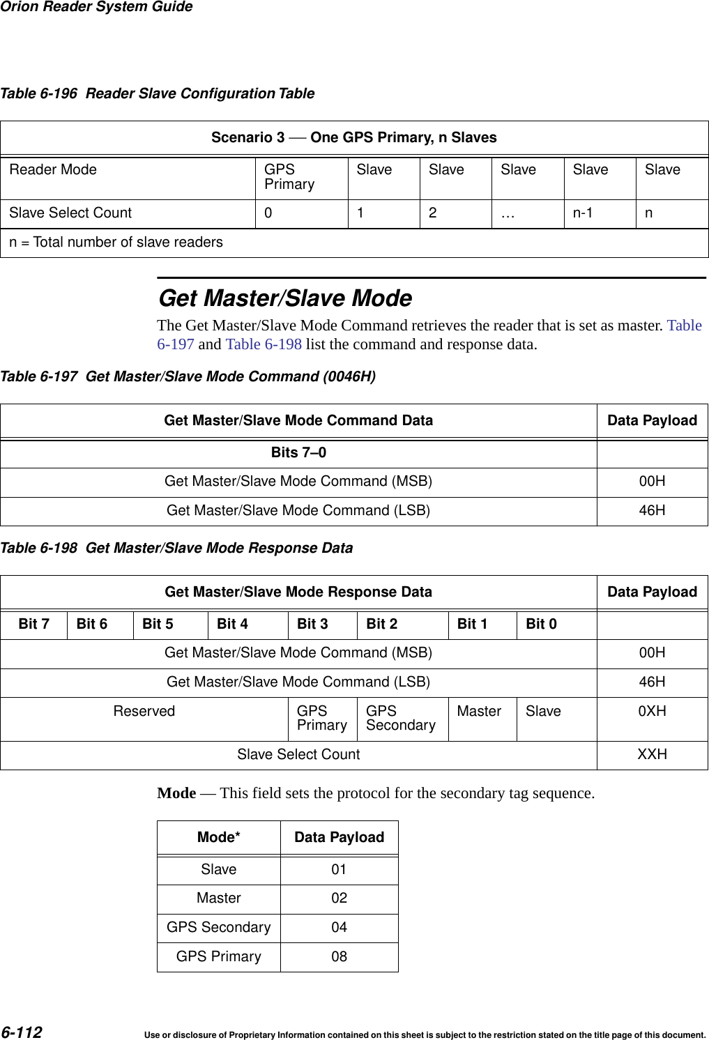
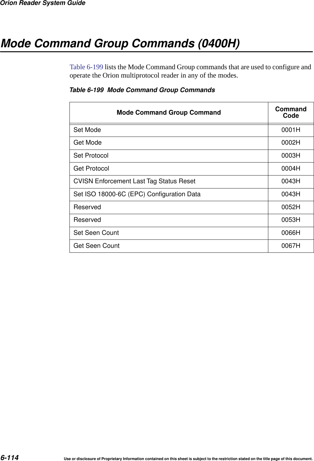
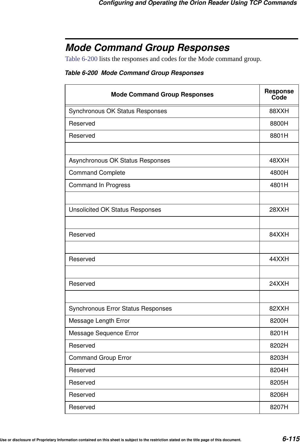
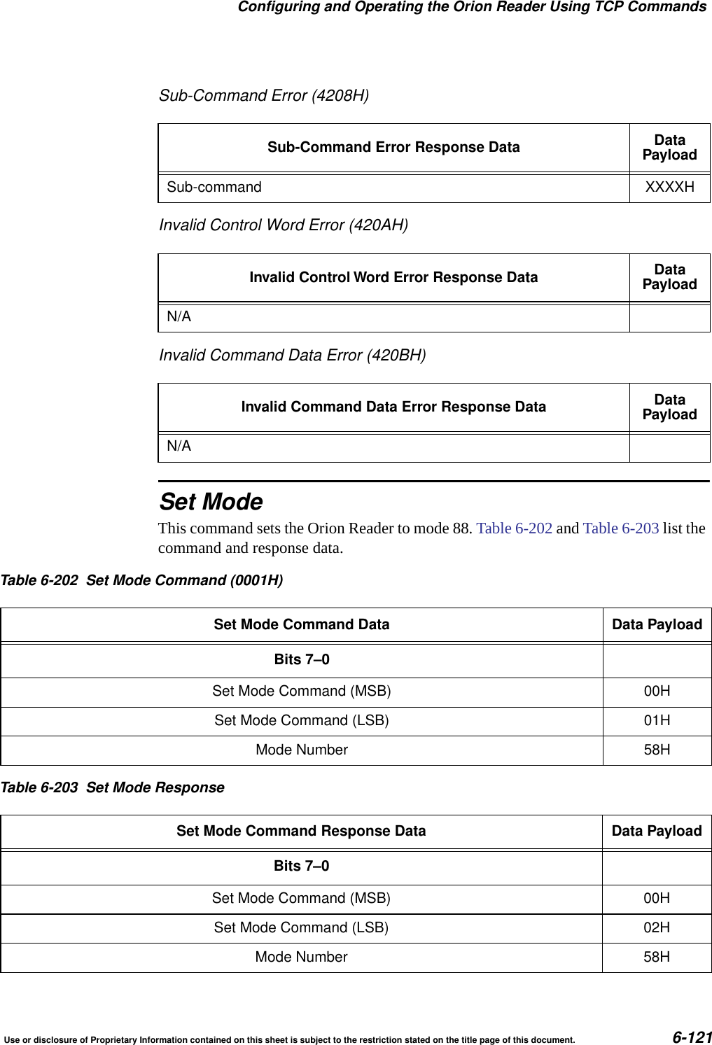
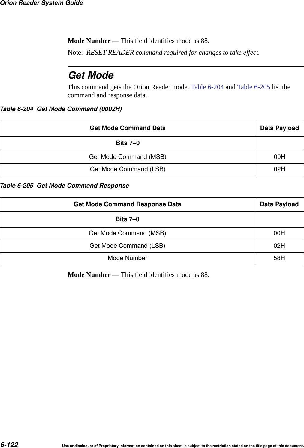
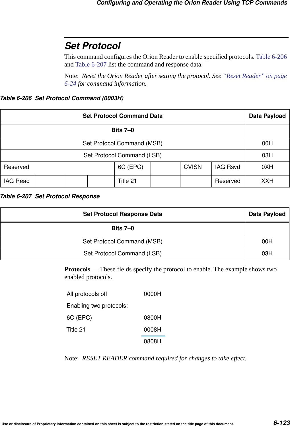
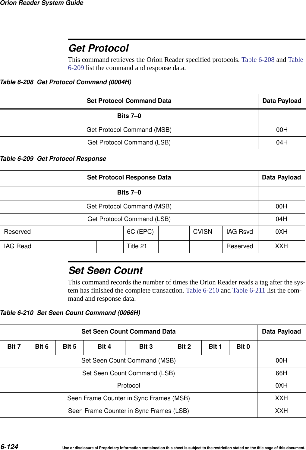
User Manual
Discussion / Help
Navigation