Star Systems ORION Location & Monitoring Transmitter User Manual
Star Systems International Limited Location & Monitoring Transmitter
Users Manual

Orion® Reader System Guide
Star Systems International, Ltd.
August 2014
P/N 16-0024-001
Use or disclosure of Proprietary Information contained on this sheet is subject to the restriction stated on the title page of this document. 1
Health Limits for Orion® Reader Using External Antenna (902 to 921.5 MHz). . . 1-4
Limites d’innocuité du lecteur OrionMD utilisé avec une antenne externe
(902 à 921,5 MHz) .................................................... 1-5
Purpose of the Guide................................................. 1-3
Intended Audience ................................................... 1-3
Guide Topics........................................................ 1-3
Typographical Conventions Used in this Manual .......................... 1-5
Assessing and Formulating a Site Plan.................................. 2-3
Preparing the Installation Site.......................................... 2-3
Site Preparation Checklist ............................................ 2-3
Components Checklist ............................................... 2-4
Task Checklist ...................................................... 2-4
Where to Mount the Components....................................... 2-4
Overhead Gantry Mount ............................................. 2-5
Overpass Mount ................................................... 2-6
Cantilever Arm Mount ............................................... 2-7
Open Road Tolling Gantry............................................ 2-8
Orion Reader Components ............................................ 3-3
Orion Reader Features................................................ 3-4
External Device Connectors .......................................... 3-4
.............................................................. 3-4
Power Supply................................................. 3-5
Selecting a Power Supply ....................................... 3-5
Connecting the Orion Reader to Power Supply ....................... 3-6
Sync .......................................................... 3-7
External Digital Input/Output Connector ............................... 3-8
Connecting to Antenna ............................................ 3-8
Connecting to Host Computer .................................... 3-9
Ethernet Connector for TCP Communications........................ 3-9
Connecting to Additional System Components......................... 3-10
Diagnostic Communications Connector (COM2) ..................... 3-10
Diagnostic Test Port Internal Connector ........................... 3-11
Global Positioning System Connector ............................. 3-11
Installing the Reader System Components .............................. 3-11
Mounting the Toll Antenna in an Overhead Location ...................... 3-12
Starting the Orion Reader ............................................ 3-14
Orion Reader System Guide
2Use or disclosure of Proprietary Information contained on this sheet is subject to the restriction stated on the title page of this document.
Resetting the Orion Reader.......................................... 3-14
Software Information ................................................. 4-3
TCP Command and Response Conventions.............................. 4-3
Lane Controller Heartbeat Controls .................................. 4-4
Sequence Number Controls ........................................ 4-4
Data Acknowledge Controls ........................................ 4-7
Use of Data Acknowledge Controls by Host and Orion Reader .......... 4-8
Communication Between Orion Reader and Host ......................... 5-3
TCP/IP Fast Ethernet Connection ...................................... 5-3
TCP/IP Fast Ethernet Communications Protocol .......................... 5-4
Command Request Message ....................................... 5-4
Data Acknowledge Message ....................................... 5-5
Command Response Message ..................................... 5-5
Asynchronous Response Message .................................. 5-5
Unsolicited Status Message ........................................ 5-5
Chapter Organization................................................. 6-3
Operating the Orion Reader in Mode 88 ................................. 6-4
Working with Mode 88............................................... 6-4
System Commands .................................................. 6-6
Command Group Bit Fields ........................................ 6-9
Unsolicited Status Bit Field......................................... 6-9
Data Acknowledge Bit Field ........................................ 6-9
Responses to System Commands ..................................... 6-10
Responses and Codes for System Commands........................... 6-10
Synchronous Response Bit Field ................................... 6-11
Asynchronous Response Bit Field .................................. 6-11
Unsolicited Response Bit Field..................................... 6-11
OK Status Bit Field .............................................. 6-12
Error Status Bit Field............................................. 6-12
Control Status Bit Field........................................... 6-12
Command Group Command Response Bit Fields ...................... 6-12
System Interface Command Group Commands (8000H) ................... 6-13
System Interface Command Group Responses .......................... 6-14
System Interface Command Group Response Data .................... 6-16
Asynchronous OK Status Responses ............................. 6-16
Synchronous Error Status Responses............................. 6-17
Asynchronous Error Status Responses ............................ 6-18
System Interface Command Group Unsolicited Status Messages ............ 6-20
System Identify ................................................... 6-21
Set Time and Date ................................................ 6-22
Get Time and Date ................................................ 6-23
Use or disclosure of Proprietary Information contained on this sheet is subject to the restriction stated on the title page of this document. 3
CPU App Firmware Download........................................ 6-23
Reset Reader .................................................... 6-24
Get Buffered Tag Transaction ........................................ 6-24
Get Number of Buffered Tag Transactions .............................. 6-25
Delete All Buffered Tag Transactions .................................. 6-26
Get System Startup Status .......................................... 6-26
Get Lane Controller Interface Status................................... 6-27
Get System Interface Status ......................................... 6-27
Set Buffered Tag Transaction Mode ................................... 6-27
Get Buffered Tag Transaction Mode ................................... 6-28
Set Data Acknowledge Time-out Period ................................ 6-28
Communication Protocols......................................... 6-29
Get Data Acknowledge Time-out Period ................................ 6-29
Set Switch Buffered Tag Transaction Mode Enable ....................... 6-30
Get Switch Buffered Tag Transaction Mode Enable ....................... 6-30
FPGA Firmware Download .......................................... 6-32
CPU Boot Firmware Download ....................................... 6-32
Get System Serial Number .......................................... 6-32
Get Firmware Version Numbers ...................................... 6-33
Load Default Operating Parameters ................................... 6-33
Set Lane Controller/Host IP Address................................... 6-34
Get Lane Controller/Host IP Address .................................. 6-34
Set IP Address and Subnet Mask ..................................... 6-35
Get IP Address and Subnet Mask ..................................... 6-36
Get TCP Port Number .............................................. 6-36
Digital I/O Command Group Commands (4000H) ......................... 6-37
Digital I/O Command Group Responses ................................ 6-38
Digital I/O Command Group Response Data .......................... 6-40
Asynchronous OK Status Responses ............................. 6-40
Synchronous Error Status Responses............................. 6-40
Asynchronous Error Status Responses ............................ 6-41
Digital I/O Asynchronous Reports ..................................... 6-43
Sensor Status Change Report ..................................... 6-43
Sensor Input Report ............................................. 6-45
Set Digital I/O Sensor Status Change Report ............................ 6-46
Get Digital I/O Sensor Status Change Report............................ 6-47
Set Digital I/O Output Host Control .................................... 6-48
Get Digital I/O Output Host Control .................................... 6-51
Set Digital I/O Output Tag Read Control ................................ 6-52
Get Digital I/O Output Tag Read Control................................ 6-52
Set Digital I/O RF Control ........................................... 6-53
Get Digital I/O RF Control ........................................... 6-55
Set Digital I/O RF Multiplexing Mode................................... 6-55
Get Digital I/O RF Multiplexing Mode .................................. 6-56
Set Digital I/O Output Pulse Duration .................................. 6-57
Get Digital I/O Output Pulse Duration .................................. 6-58
Set Digital I/O Minimum Presence True Period........................... 6-60
Orion Reader System Guide
4Use or disclosure of Proprietary Information contained on this sheet is subject to the restriction stated on the title page of this document.
Get Digital I/O Minimum Presence True Period .......................... 6-61
Set Digital I/O Sensor Input Inversion .................................. 6-62
Get Digital I/O Sensor Input Inversion.................................. 6-63
Set Digital I/O Port Configuration ..................................... 6-63
Get Digital I/O Port Configuration ..................................... 6-64
Set Digital I/O Sensor Input Report .................................... 6-66
Get Digital I/O Sensor Input Report.................................... 6-66
Set Digital I/O Presence RF Control Algorithm ........................... 6-66
Get Digital I/O Presence RF Control Algorithm ........................... 6-67
Set Digital I/O Presence RF Control Time-out Period ...................... 6-69
Get Digital I/O Presence RF Control Time-out Period...................... 6-70
Get Digital I/O Port Status ........................................... 6-71
Set Digital I/O Mode ............................................... 6-73
Get Digital I/O Mode ............................................... 6-73
Set External Interrupt Control ........................................ 6-74
Get External Interrupt Control ........................................ 6-76
RF Transceiver Command Group Commands (2000H) .................... 6-77
RF Transceiver Command Group Responses ........................... 6-78
RF Transceiver Command Group Response Data...................... 6-80
Synchronous OK Status Responses .............................. 6-80
Synchronous Error Status Responses............................. 6-80
Asynchronous Error Status Responses ............................ 6-81
Set RF Attenuation ................................................ 6-83
Get RF Attenuation ................................................ 6-84
Set Data Detect ................................................... 6-85
Get Data Detect................................................... 6-86
Set Line Loss..................................................... 6-87
Get Line Loss .................................................... 6-88
Set Uplink Source Control ........................................... 6-88
Get Uplink Source Control........................................... 6-89
Set Frequency in MHz ............................................. 6-90
Get Frequency in MHz ............................................. 6-93
Tag Transaction Configuration Command Group
Commands (1000H) ................................................. 6-95
Tag Transaction Configuration Command Group Responses................ 6-96
Tag Transaction Configuration Command Group Response Data.......... 6-98
Asynchronous OK Status Responses ............................. 6-98
Synchronous Error Status Responses............................. 6-98
Asynchronous Error Status Responses ............................ 6-99
Set Asynchronous Response Append Data ............................ 6-101
Formats for Time and Date Time-stamp .......................... 6-102
Get Asynchronous Response Append Data ............................ 6-102
Set Manual Antenna Channel Control................................. 6-104
Get Manual Antenna Channel Control ................................ 6-104
Get Universal Configuration Table Version Number ...................... 6-105
Set IAG Slot..................................................... 6-105
Use or disclosure of Proprietary Information contained on this sheet is subject to the restriction stated on the title page of this document. 5
Get IAG Slot .................................................... 6-106
Set Secondary Tag Sequence....................................... 6-107
Get Secondary Tag Sequence ...................................... 6-108
Set Master/Slave Mode ............................................ 6-109
Get Master/Slave Mode............................................ 6-112
Mode Command Group Commands (0400H)............................ 6-114
Mode Command Group Responses .................................. 6-115
Mode Command Group Response Data............................. 6-118
Asynchronous OK Status Responses ............................ 6-118
Synchronous Error Status Responses............................ 6-118
Asynchronous Error Status Responses ........................... 6-119
Set Mode ....................................................... 6-121
Get Mode....................................................... 6-122
Set Protocol..................................................... 6-123
Get Protocol..................................................... 6-124
Set Seen Count .................................................. 6-124
Get Seen Count.................................................. 6-125
Diagnostic Command Group Commands (0200H) ....................... 6-127
Diagnostic Command Group Responses .............................. 6-127
Diagnostic Command Group Response Data......................... 6-129
Asynchronous OK Status Responses ............................ 6-129
Synchronous Error Status Responses............................ 6-131
Asynchronous Error Status Responses ........................... 6-131
Unsolicited Diagnostic Status Reports ................................ 6-133
Get Diagnostic Status ............................................. 6-133
Diagnostic Status Bit Definitions................................... 6-135
Get Diagnostic Interface Status...................................... 6-138
Get Error Log.................................................... 6-138
Get Number of Error Logs .......................................... 6-139
Clear Error Logs ................................................. 6-139
TCP Tag Responses.................................................. 7-3
TCP Tag Response Field Definitions ................................... 7-3
Specific TCP Tag Responses .......................................... 7-3
Title 21 Read Response ............................................. 7-4
Record Type .................................................... 7-4
Tag Type....................................................... 7-4
Internal Tag ID .................................................. 7-4
CRC .......................................................... 7-4
Facility Code .................................................... 7-5
Title 21 Read Response Example: ................................... 7-5
CVISN Seen Frame Counter Report .................................... 7-6
Seen Frame Counter Report .......................................... 7-8
CVISN Read Response.............................................. 7-8
IAG Read Response ................................................ 7-9
Orion Reader System Guide
6Use or disclosure of Proprietary Information contained on this sheet is subject to the restriction stated on the title page of this document.
IAG Cross-Lane Read Response ..................................... 7-13
IAG Cross-Lane Read Response Example ......................... 7-14
Why You Need to Configure a Lane ..................................... 8-3
Marking the Read Zone ............................................... 8-3
Required Supplies .................................................. 8-4
Guidelines ........................................................ 8-4
Lane Configuration Examples ......................................... 8-5
Lane Configuration Parameters for Title 21 Protocols....................... 8-6
Error Indicators ..................................................... 9-3
Troubleshooting Guidelines ........................................... 9-4
Communicating Via Diagnostic Port (COM2) ............................. 9-4
Diagnostic COM2 Port Pin Assignments................................. 9-5
Starting the Terminal Emulation Software................................ 9-5
Diagnostic Commands ............................................... 9-8
bootChange...................................................... 9-10
Power Cycling the Orion Reader...................................... 9-11
Error Log Reference
System Initialization Module Errors .................................... 9-15
Lane Controller Interface Module Errors ................................ 9-15
System Interface Module Errors ...................................... 9-17
Mode Interface Module Error Numbers ................................. 9-18
Tag Interface Module Error Numbers .................................. 9-18
Sync Module Error Numbers ......................................... 9-20
GPS Module Error Numbers ......................................... 9-20
RF Transceiver Interface Module Error Numbers ......................... 9-21
Diagnostic Module Error Numbers .................................... 9-26
Tag Buffer Module Error Numbers .................................... 9-27
Digital Input/Output Module Error Numbers ............................. 9-28
Hardware Preventive Maintenance and Troubleshooting Procedures ........ 9-28
Hardware Preventive Maintenance Schedule ............................ 9-29
Visual Inspection .................................................. 9-29
Replacement Instructions for Orion Reader and AVI Equipment ............ 9-30
Replacing a Transmit/Receive Antenna on a
Gantry .......................................................... 9-31
Preventive Maintenance Schedule ..................................... 9-33
Removal and Replacement Procedures ................................ 9-33
Transmit/Receive Antenna .......................................... 9-33

Use or disclosure of Proprietary Information contained on this sheet is subject to the restriction stated on the title page of this document. 7
Removal ...................................................... 9-33
Replacement................................................... 9-34
Antenna Cable.................................................... 9-34
Removal ...................................................... 9-34
Replacement................................................... 9-34
.................................................................. 9-34
A Acronyms and Glossary
Acronyms and Glossary .............................................. 1-3
B Hardware Interfaces
Hardware Interfaces.................................................. 1-3
Communications ................................................... 1-4
TCP/IP Fast Ethernet Connection .................................. 1-4
Sync/COM1 Port................................................. 1-5
External Digital Input/Output Connector ............................... 1-5
C System Technical Specifications
Component Specifications ............................................ 1-3
Orion Reader...................................................... 1-3
Toll Antenna ...................................................... 1-3
Environmental Specifications ....................................... 1-4
D Orion Reader Options
Orion Reader Options ................................................ 1-3
Digital Input/Output Modules .......................................... 1-4
Required Components/Tools.......................................... 1-4
Installation/Mounting/Grounding of the Reader............................ 1-5
Testing the Digital I/O Components Using TCP Commands.................. 1-7
Guidelines for Ordering the I/O Modules ................................. 1-8
Global Positioning System Timing Option .............................. 1-10
GPS Power and Data Connector ................................... 1-12
Before Installing the GPS Antenna .................................... 1-13
Required Components/Tools......................................... 1-14
GPS Timing Assembly Mounting...................................... 1-14
GPS Antenna Mounting............................................. 1-14

Orion Reader System Guide
8Use or disclosure of Proprietary Information contained on this sheet is subject to the restriction stated on the title page of this document.
Testing the GPS Timing System ...................................... 1-16
Using the TCP Command Set ..................................... 1-17
Configuring the Reader/Slave Count ................................ 1-17
Environmental .................................................... 1-19
Temperature Range for GPS Assembly .............................. 1-19
Humidity ...................................................... 1-19
GPS Antenna .................................................. 1-20
GPS Assembly Connector .......................................... 1-20
GPS Diagnostic Port............................................. 1-20
GPS Antenna Cable ............................................. 1-20
Regulatory Requirements ........................................... 1-20
Emissions ..................................................... 1-20
Safety ........................................................ 1-20
Electrical Protection................................................ 1-21
ESD ......................................................... 1-21
Antenna Drive and Protection Circuitry............................... 1-21
Antenna Drive Current Limits.................................... 1-21
Troubleshooting the GPS System ................................ 1-22
E Command-Based Pre- and Post-Conditions
TCP Command Pre- and Post-Conditions ................................ 1-3
© 2014 Orion Reader System Guide. All rights reserved. Contents are subject to change. Printed in the
U.S.A.
For further information, contact:

WARNING TO USERS IN THE UNITED STATES AND CANADA
FEDERAL COMMUNICATIONS COMMISSION (FCC)
LOCATION AND MONITORING SERVICE STATEMENT
47 CFR §90.351
NOTE: The user is required to obtain a Part 90 site license from the Federal Communications Commission
(FCC), or an equivalent delivered by Industry Canada (IC), to operate this radio frequency identification
(RFID) device in the United States or Canada. FCC ID number is 2AA7K-ORION. IC ID number is
20068-ORION. Access the FCC website at www.fcc.gov/Forms/Form601/601.html or at http://
wireless.fcc.gov/index.htm?job=online_filing or at the IC website at http://www.ic.gc.ca/eic/site/sd-sd.nsf/
eng/h_00023.html to obtain additional information concerning licensing requirements.
NOTE: Users in all countries should check with the appropriate local authorities for licensing
requirements.
FCC RADIO FREQUENCY INTERFERENCE STATEMENT
47 CFR §15.105(a)
NOTE: This equipment has been tested and found to comply with the limits for a Class A digital device
pursuant to Part 15 of the FCC rules. These limits are designed to provide reasonable protection against
harmful interference when the equipment is operated in a commercial environment. This equipment
generates, uses, and can radiate RF energy and may cause harmful interference to radio communications if
not installed and used in accordance with the instruction manual. Operating this equipment in a residential
area is likely to cause harmful interference, in which case, depending on the regulations in effect, the user
may be required to correct the interference at their own expense.
NO UNAUTHORIZED MODIFICATIONS
47 CFR §15.21
CAUTION: This equipment may not be modified, altered, or changed in any way without permission.
Unauthorized modification may void the equipment authorization from the FCC and will void the
warranty.
USE OF SHIELDED CABLES AND GROUNDING
47 CFR §15.27(a)
NOTE: Shielded cables and Earth Grounding the unit is recommended for this equipment to comply with
FCC regulations.
USA

AVERTISSEMENT POUR LES UTILISATEURS DES ÉTATS-UNIS ET DU CANADA
DÉCLARATION SUR L’UTILISATION ET L’EMPLACEMENT DES APPAREILS,
CONFORMÉMENT AUX EXIGENCES DE LA FCC (COMMISSION FÉDÉRALE DES
COMMUNICATIONS DES ÉTATS-UNIS)
47 CFR §90.351
NOTE : L’utilisateur est tenu d’obtenir une licence de site de la FCC aux termes de la partie 90 du Code des
règlements fédéraux des États-Unis (CFR), ou un équivalent délivré par Industrie Canada (IC), pour pouvoir
se servir de ce dispositif d’identification par radiofréquence (RFID) aux États-Unis et au Canada. Le numéro
d’identification pour la FCC est 2AA7K-ORION. Le numéro d’identification pour IC est 20068-ORION.
Prière de consulter le site Web de la FCC au www.fcc.gov/Forms/Form601/601.html ou au http://
wireless.fcc.gov/index.htm?job=online_filing, ou encore le site Web d’IC à http://www.ic.gc.ca/eic/site/sd-
sd.nsf/fra/h_00023.html?Open&src=mm1, pour obtenir des renseignements supplémentaires sur les exigences
en matière de licence.
NOTE : Les utilisateurs de tous les pays sont priés de vérifier, auprès des autorités concernées, les
exigences locales en matière de licence.
DÉCLARATION SUR LE BROUILLAGE RADIOÉLECTRIQUE, CONFORMÉMENT AUX
EXIGENCES DE LA FCC
47 CFR §15.105(a)
NOTE : Cet appareil a été testé et jugé conforme aux limites établies pour un dispositif numérique de
classe A, selon la partie 15 des règlements de la FCC. Ces limites visent à assurer un degré raisonnable de
protection contre le brouillage préjudiciable lorsque l’appareil est utilisé dans un environnement commercial.
Cet appareil génère, utilise et peut diffuser de l’énergie sous forme de radiofréquences (RF) et peut causer un
brouillage préjudiciable aux communications radio s’il n’est pas installé conformément au mode d’emploi.
L’utilisation de cet appareil en zone résidentielle est susceptible de causer un brouillage préjudiciable, auquel
cas, selon la réglementation applicable, l’utilisateur pourrait être tenu d'éliminer le signal parasite à ses
propres frais.
AUCUNE MODIFICATION SANS AUTORISATION
47 CFR §15.21
MISE EN GARDE : Cet appareil ne peut en aucune façon être modifié, altéré ou transformé sans
l’autorisation. Toute modification non autorisée pourrait invalider l’autorisation de la FCC au regard de
l’appareil et annulera la garantie.
UTILISATION DE CÂBLES BLINDÉS ET MISE À LA TERRE
47 CFR §15.27(a)
NOTE : Il est recommandé d’utiliser des câbles blindés et de mettre l’appareil à la terre pour assurer la
conformité aux règlements de la FCC.
États-Unis

Health Limits for Orion®Reader Using External
Antenna (902 to 921.5 MHz)
Within the United States, environmental guidelines regulating safe exposure levels are issued by the Occu-
pational Safety and Health Administration (OSHA).
Section 1910.97 of OSHA Safety and Health Standards 2206 legislates a maximum safe exposure limit of
10 milliwatts per square centimeter (mW/cm2) averaged over 6 minutes at 902 MHz.
Industry Canada, RSS-102, Issue 5 guidelines recommend a maximum safe power density in W/m2 of:
Thus, the maximum permissible exposure for general population/uncontrolled exposure at 915 MHz is
2.77 W/m2. The average time is 6 minutes.
The maximum permissible exposure for occupational/controlled exposures is 19.53 W/m2. The average
time is 6 minutes.
The RF power density generated by the Orion Reader was calculated using a maximum antenna gain of
14.0 dBi, equivalent to the antenna gain of the external toll antenna.
Warning
At 1.6 W transmitted power, 0 dB transmit attenuation, and a distance of 42.5 inches (108 cm) from the
antenna, the maximum power density calculated was less than 2.77 W/m2. Install the antenna at least
42.5 inches (108 cm) from the general public. Maintenance personnel must remain at least 16.4 inches
(41 cm) from the antenna when the system is operating.
The data confirms that when an antenna is used with the Orion Reader, the antenna effectively meets
OSHA requirements and thus does not represent an operating hazard to either the general public or mainte-
nance personnel.
(0.02619)(Frequency (in MHz))0.6834 = (0.02619)(915)0.6834 = 2.77 W/m2

Limites d’innocuité du lecteur OrionMD utilisé avec une
antenne externe (902 à 921,5 MHz)
Aux États-Unis, les directives environnementales concernant les niveaux d’exposition acceptables sont émises
par l’OSHA (Occupational Safety and Health Administration).
L’article 1910.97 de la norme de santé et de sécurité 2206 de l’OSHA fixe la limite d’exposition acceptable à
une moyenne de 10 milliwatts par centimètre carré (mW/cm2) sur une période de 6 minutes à 902 MHz.
Les normes de l’Industrie Canada, CNR-102, 5e édition recommandent de ne pas dépasser la densité de puis-
sance suivante, exprimée en W/m2 :
Ainsi, le niveau maximal d’exposition permis pour la population générale et les situations d’exposition non
contrôlée à 915 MHz est de 2,77 W/m2 en moyenne sur une période de 6 minutes.
Le niveau maximal d’exposition permis dans un cadre professionnel ou contrôlé est de19,53W/m2 en
moyenne sur une période de 6 minutes.
La densité de puissance des RF générées par le lecteur Orion a été calculée pour un gain d’antenne maximal de
14,0 dBi, soit l’équivalent du gain de l’antenne de péage universelle.
Mise en garde
Avec une puissance transmise de 1,6 W et une atténuation de transmission de 0 dB, la densité de puissance
maximale calculée à 42,5 pouces (108 cm) de l’antenne était inférieure à 2,77 W/m2. Par mesure de précau-
tion, installer l’antenne à au moins 42,5 pouces (108 cm) de la population générale. Le personnel d’entre-
tien doit se tenir à au moins 16,4 pouces (41 cm) de l’antenne lorsque le système est en cours d’utilisation.
Les données confirment que l’utilisation de l’toll antenna ou d’une antenne équivalente avec le lecteur multi-
protocole Orion répond aux exigences de l’OSHA et ne présente pas de danger lié à son utilisation, que ce soit
pour la population générale ou le personnel d’entretien.
(0,02619)(Fréquence (en MHz))0,6834 =(0,02619)(915)0,6834 =2,77 W/m2
Orion Reader System Guide
6Use or disclosure of Proprietary Information contained on this sheet is subject to the restriction stated on the title page of this document.

1
Before You Begin

Before You Begin
Use or disclosure of Proprietary Information contained on this sheet is subject to the restriction stated on the title page of this document. 1-3
Chapter 1 Orion Reader System Guide
Before You Begin
This chapter provides an overview of the Orion® Reader System Guide.
Purpose of the Guide
This Orion® Reader System Guide provides detailed information about the reader sys-
tem, including site installation and planning, troubleshooting, and preventive mainte-
nance tasks, as well as a detailed list of the reader software commands and diagnostic
and hardware interface information for developing your customized application soft-
ware. Also included is an appendix that describes the optional assemblies available
with the Orion system.
Intended Audience
The intended audience for this guide is those personnel responsible for installing, con-
figuring, operating, and maintaining the Orion Reader.
Guide Topics
This system guide presents the following information.
Chapter 1 –BeforeYou Begin This chapter provides an overview of the system guide as
well as related documents, typographical conventions, and
licensing requirements.
Chapter 2 –Developing the Orion Reader
System Site Plan This chapter discusses factors to be considered when
developing the site plan in preparation for installing the Orion
Reader system equipment.
Chapter 3 –Installing the Orion Reader This chapter describes the Orion Reader and instructs the
user in installing the Orion Reader system.
Chapter 4 –Software Information This chapter provides transmission control protocol (TCP)
software-related information for the Orion Reader.
Chapter 5 –Communication Protocols This chapter describes the TCP communications via
Ethernet for the Orion Reader.
Chapter 6 –Configuring and Operating the
Orion Reader Using TCP Commands This chapter describes the Orion Reader mode and TCP
commands that are used to configure and operate the
reader. This chapter also contains system commands and
responses that are needed to develop host software for the
TCP command set.
Orion Reader System Guide
1-4 Use or disclosure of Proprietary Information contained on this sheet is subject to the restriction stated on the title page of this document.
Chapter 7 –Tag Responses This chapter provides tag responses for transmission control
protocol (TCP)
Chapter 8 –Configuring the Lane This chapter provides information on the importance of lane
tuning for optimum automatic vehicle identification (AVI)
system performance. This chapter also describes the Orion
Reader functions and features that can assist you in tuning
an AVI lane.
Chapter 9 –System Diagnostics and
Preventive Maintenance This chapter provides information on error messages,
troubleshooting, preventive maintenance schedule, visual
inspection, Orion Reader repair, removal and replacement
procedures, and technical support.
Appendix A –Acronyms and Glossary This appendix defines the acronyms and terms used in this
system guide.
Appendix B –Hardware Interfaces This appendix describes the physical interconnections within
an Orion Reader system.
Appendix C –System Technical
Specifications This appendix provides reference specifications for the
Orion Reader system components.
Appendix D –Reader System Options This appendix describes the options available with the Orion
Reader system.
Appendix E –Command-Based Pre- and
Post Conditions This appendix lists the pre- and post-conditions for TCP
commands.
Index This index provides an alphabetical listing of the system
guide topics.
Before You Begin
Use or disclosure of Proprietary Information contained on this sheet is subject to the restriction stated on the title page of this document. 1-5
Typographical Conventions Used in this Manual
Table 1-1 lists the typographical conventions that may be used in this manual. Not all
of the conventions are used in this version.
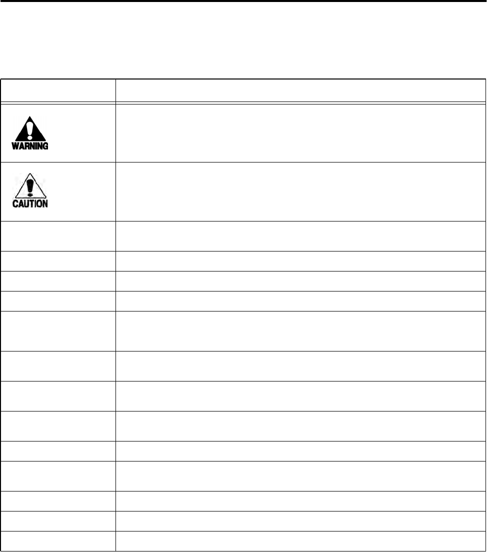
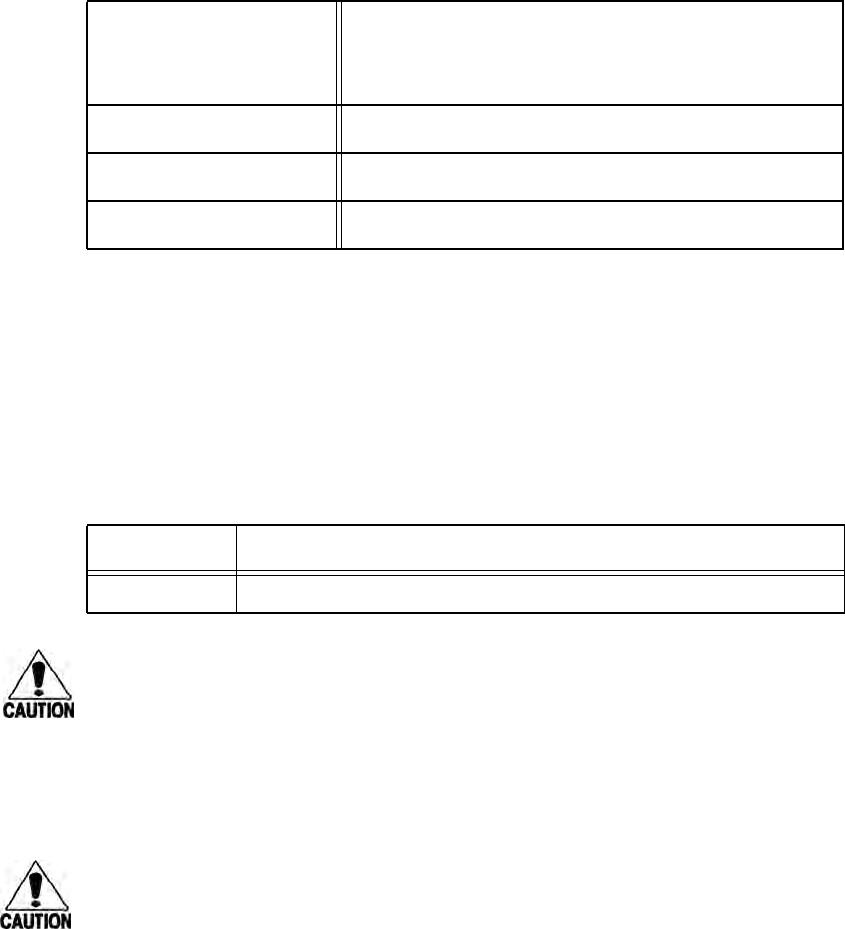
Table 1-1 Typographical Conventions
Convention Indication
This procedure might cause harm to the equipment and/or the user.
A caution sign indicates concerns about a procedure.
Code Code, including keywords and variables within text and as separate paragraphs,
and user-defined program elements within text appear in courier typeface.
Dialog Box Title Title of a dialog box as it appears on screen.
Screen Title Title of a screen as it appears on screen.
Menu Item Appears on a menu.
Note Additional information that further clarifies the current discussion. These
important points require the user’s attention. The paragraph is in italics and the
word Note is bold.
Cancel button Bold text identifies the labeling of items as they actually appear on the keyboard,
on a button, as a menu item, and so forth.
Ctrl-Esc A hyphen indicates actions you should perform simultaneously. For example, Ctrl-
Esc means to press the Ctrl and Esc keys at the same time.
5 Return A space indicates that you should press the specified keys in the sequence listed,
not at the same time.
before Text in italics indicates emphasis.
Customer >Find Bold text followed by a > and more bold text indicates the order of command
selections to reach a specific function.
click Click means that you should press and release the left mouse button.
cursor The cursor is the flashing vertical line that appears in a selected edit box.
pointer The pointer is the arrow in the window that shows the movement of the mouse.
Orion Reader System Guide
1-6 Use or disclosure of Proprietary Information contained on this sheet is subject to the restriction stated on the title page of this document.

2
Developing the Installation Site Plan

Developing the Installation Site Plan
Use or disclosure of Proprietary Information contained on this sheet is subject to the restriction stated on the title page of this document. 2-3
Chapter 2
Developing the Installation Site Plan
This chapter provides guidelines for the following tasks:
•Assessing and formulating the site plan
•Preparing the site
•Choosing locations to mount the system components
•Determining electrical and communications requirements
Assessing and Formulating a Site Plan
You will need to perform a general geographic RF site survey to check for RF noise
sources near the automatic vehicle identification (AVI) installation.
You will need to formulate a frequency plan for each plaza. Each reader has two fre-
quencies: downlink (reader-to-tag communications) and uplink (tag-to-reader
responses). An Orion Reader deployed for use in the U.S. uses the following fre-
quency ranges:
•Downlink: 911.75 to 919.75 MHz, adjustable in 0.25 MHz steps
•Uplink: 902.25 to 903.75 MHz and 910.00 to 921.50 MHz, adjustable in 0.25
MHz steps. Actual frequency range is protocol dependent.1
Consult with the Star Systems engineer or other systems integrator assisting with the
installation of the Orion Readers.
Preparing the Installation Site
Prepare the site according to the design parameters determined by your system inte-
grator.
Site Preparation Checklist
Complete the following tasks, depending on the individual site.
1. The above frequency ranges are in the location monitoring service band.
Acquire a construction license.
Acquire a Federal Communications Commission (FCC) license.
Orion Reader System Guide
2-4 Use or disclosure of Proprietary Information contained on this sheet is subject to the restriction stated on the title page of this document.
You will need to determine if Sync is required in your installation. If Sync is required,
then you may need to wire the installation for Sync configuration. Chapter 9 contains
detailed Sync information. You can also use a GPS option if hardwiring is not an
option. See Appendix D for more information on the GPS timing assembly option.
Components Checklist
Ensure you have the following components available for the installation:
Orion Reader(s)
One toll antenna for each lane
All optional equipment to the basic Orion Reader. Appendix D lists the optional
equipment that can be used with the Orion Reader.
Task Checklist
The following checklist summarizes the installation procedure. Instructions for each
task are provided in the “Mounting the Orion Reader” section in Chapter 3.
Where to Mount the Components
The location for mounting the components is designated in the site installation plan.
Many AVI site layouts are similar.
The Orion Reader can be installed in a housing along with the host computer or lane
controller.
Acquire an environmental assessment permit.
Ensure that you have assembled all the lights, buzzers, and vehicle detectors
that will interface with the Orion Reader system.
Ensure that you have software for a desktop or laptop computer to interface with
the Orion Reader firmware.
Pull communications, coaxial, and power cables through outdoor-grade conduit.
Ensure that construction work required for mounting the equipment is
completed.
Ensure that 120V AC service is available.
Install Orion Reader (and any options).
Connect power cable from power supply to Orion Reader.
Install antenna(s) and connect them to Orion Reader.
Developing the Installation Site Plan
Use or disclosure of Proprietary Information contained on this sheet is subject to the restriction stated on the title page of this document. 2-5
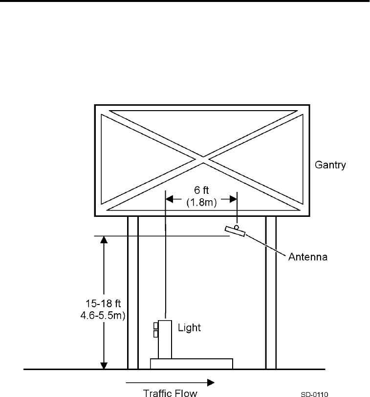
Overhead Gantry Mount
For an overhead gantry mount, the Orion Reader is installed with the host computer or
lane controller. The toll antenna may be attached to a 2- to 3-inch (5.0- to 7.6-cm)
diameter pipe that is supported from a gantry that spans the lanes. These components
are mounted approximately 15 to 18 feet (4.5 to 5.5 m) above the road surface. Figure
2-1 illustrates a typical overhead gantry mount.
Figure 2-1 Overhead Gantry Mount
Orion Reader System Guide
2-6 Use or disclosure of Proprietary Information contained on this sheet is subject to the restriction stated on the title page of this document.
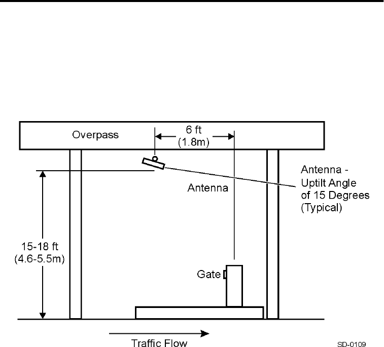
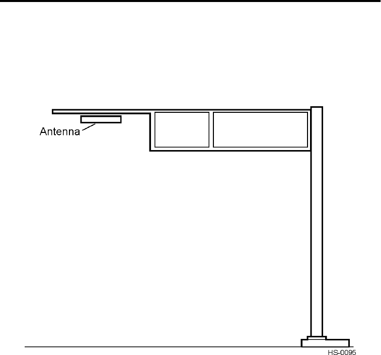
Overpass Mount
For the overpass mount, the Orion Reader is installed with the host computer or lane
controller. The toll antenna is attached to a 2- to 3-inch (5.0- to 7.6-cm) diameter pipe
that is supported from an overpass. The toll antenna is centered over the traffic lane
and is mounted approximately 15 to 18 feet (4.5 to 5.5 m) above the road surface. Fig-
ure 2-2 illustrates a typical overpass mount.
Figure 2-2 Overpass Mount
Developing the Installation Site Plan
Use or disclosure of Proprietary Information contained on this sheet is subject to the restriction stated on the title page of this document. 2-7
Cantilever Arm Mount
For the cantilever arm mount, the Orion Reader is installed with the host computer or
lane controller. The toll antenna is attached to a 2- to 3-inch (5.0- to 7.6-cm) diameter
pipe at the end of the cantilever arm. The toll antenna is centered over the traffic lane
and is mounted approximately 15 to 18 feet (4.5 to 5.5 m) above the road surface. Fig-
ure 2-3 illustrates a typical laneside cantilever arm mount with an antenna.
Figure 2-3 Cantilever Arm Mount
Orion Reader System Guide
2-8 Use or disclosure of Proprietary Information contained on this sheet is subject to the restriction stated on the title page of this document.
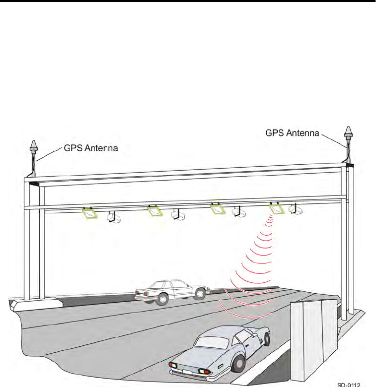
Open Road Tolling Gantry
For typical ORT gantry installations, the Orion Reader may be installed in a laneside
equipment cabinet. The toll antenna is attached to a 2- to 3-inch (5.0- to 7.6-cm) diam-
eter pipe mounted approximately 15 to 18 feet (4.5 to 5.5 m) above the road surface.
For ORT applications, one set of toll antennas may be centered over the lane and a
second set of toll antennas may be centered over the stripes dividing the lanes (Figure
2-4). This configuration ensures that vehicle traffic, traveling inside and outside the
lanes, is covered by the toll antennas.
Figure 2-4 ORT Gantry Mount

3
Installing the Orion Reader

Installing the Orion Reader
Use or disclosure of Proprietary Information contained on this sheet is subject to the restriction stated on the title page of this document. 3-3
Chapter 3
Installing the Orion Reader
This chapter describes the Orion® Reader system and provides
instructions for installing the Orion Reader system.
Orion Reader Components
Star Systems’ Orion Reader is an integrated, multiprotocol 915-MHz radio frequency
identification (RFID) reader system that includes an RF transceiver board and proces-
sor in a single assembly.
The Orion Reader is suitable for a wide variety of automatic vehicle identification
applications, including airport ground transportation management systems, parking,
secure access, and rail applications.
The Orion Reader can be installed in a cabinet with a host computer or onsite lane
controller, or alone in a NEMA enclosure.
The Orion Reader transmits and receives signals through a single antenna.
The Orion Reader is capable of reading tags of any of the following protocols in a
given installation:
•ISO 18000-6C (EPC)
•California Title 21
•Interagency Group (IAG)
•CVISN (ASTM Draft 6)
Caution
Where multiple tag protocols are used in the same installation, an Orion Reader
operating in Mode 88 is capable of reading any combination of the protocols; how-
ever, no more than two protocols should be used for high speed operations.
Orion Reader System Guide
3-4 Use or disclosure of Proprietary Information contained on this sheet is subject to the restriction stated on the title page of this document.
Orion Reader Features
The following sections describe the Orion Reader features and list the specifications
for the external connections and performance indicators located in the Orion Reader
housing.
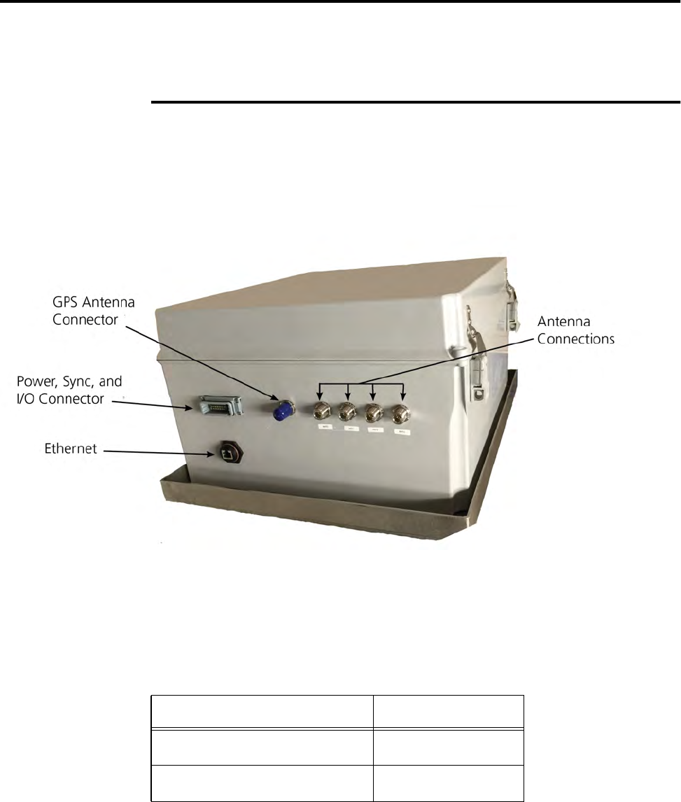
External Device Connectors
This section lists the Orion Reader connectors. Figure 3-1 shows the Orion Reader
connector and indicator locations. Table 3-1 shows the pin assignments for the Power,
Sync, and I/O Connector.
Figure 3-1 Connector Locations on the Orion Reader
Table 3-1 Power, Sync, and I/O Connector Pin Assignments (DB15)
Wire Pin No
Power +24V 5
Power +24V 6

Installing the Orion Reader
Use or disclosure of Proprietary Information contained on this sheet is subject to the restriction stated on the title page of this document. 3-5
Power Supply
The Orion Reader requires 19V DC to 30V DC or 19V AC to 27V AC RMS power
supply. Table 3-2 lists the external power connector specifications. Star Systems
offers a Class B transformer accessory kit (part number 76-6000-001) for sites where
either 110V AC or 220V AC is available. Accessory kit information is shown in Table
3-3.
Selecting a Power Supply
Power Return 7
Power Return 8
Sync- 3
Sync+ 4
I/O 1 1
I/O 1 Return 15
I/O 2 14
I/O 2 Return 13
I/O 3 12
I/O 3 Return 11
I/O 4 10
I/O 4 Return 9
Table 3-2 Orion Reader External Power Connector Specifications
Connector Type DB15 Connector
Wire Gauge
12–22AWG
Note Installer must consider the wire resistance
versus overall length with respect to the Orion
Reader’s specified voltage range
Table 3-1 Power, Sync, and I/O Connector Pin Assignments (DB15)
Wire Pin No
Orion Reader System Guide
3-6 Use or disclosure of Proprietary Information contained on this sheet is subject to the restriction stated on the title page of this document.
You should consider the following factors when selecting a power supply.
•Input voltage: 19V to 30V DC, or 19V to 27V AC RMS @47 to 63 Hz
•Operating temperature of the power supply and the power cable
•Power cord gauge and length. Star Systems recommends that you use 12 to 22
AWG cable for the power cord.
Table 3-3 Orion Power Supply Accessory Kit
Part Number Description
76-6000-001 110V AC or 220V AC to 24 V AC Class B transformer
CAUTION
Wire gauge depends on wire resistance versus overall wire length with respect to the
Orion Reader’s specified voltage range and power rating.
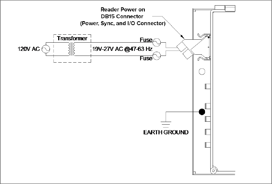
Connecting the Orion Reader to Power Supply
Star Systems strongly recommends that you connect the Orion Reader to the power
supply as shown in Figure 3-2.
Caution
Loosen mounting screws on power supply connector before removing plug.
Input Supply Voltage
19V to 30V DC
19V to 27V AC RMS
Note See Figure 3-2 for AC power source wiring and
Figure 3-3 for DC power source wiring.
Input Power DC or AC: 40 watts maximum
In-Rush Current 8 amps maximum, 25 milliseconds
Polarity Power supply is polarity independent
Table 3-2 Orion Reader External Power Connector Specifications (continued)
Installing the Orion Reader
Use or disclosure of Proprietary Information contained on this sheet is subject to the restriction stated on the title page of this document. 3-7
Figure 3-2 Connecting Reader to Power Supply
Sync
At installations where cross-lane interference can occur and frequency management is
not sufficient to solve the problem, you may need to use Sync. By using the Sync
function in the Orion Readers, the readers operate only during interleaved time peri-
ods.
Note: In sites where installing Sync cabling is not an option, you can use the global
positioning system (GPS) timing alternative. See Appendix D, “Orion Reader
Options,” for more information.
The Orion Reader can support multiple lanes using Sync cabling. This connection pro-
vides a synchronization interface between readers where RF interference between
readers is reduced by multiplexing the RF reader transmission to independent time
slots. Allowing each reader or group of readers to operate at an allotted time elimi-
nates interference from readers in adjacent lanes.
Although you need to configure the readers to operate using Sync, the interface con-
nection for Sync, can be provided to all the readers in a plaza before or during installa-
Orion Reader System Guide
3-8 Use or disclosure of Proprietary Information contained on this sheet is subject to the restriction stated on the title page of this document.
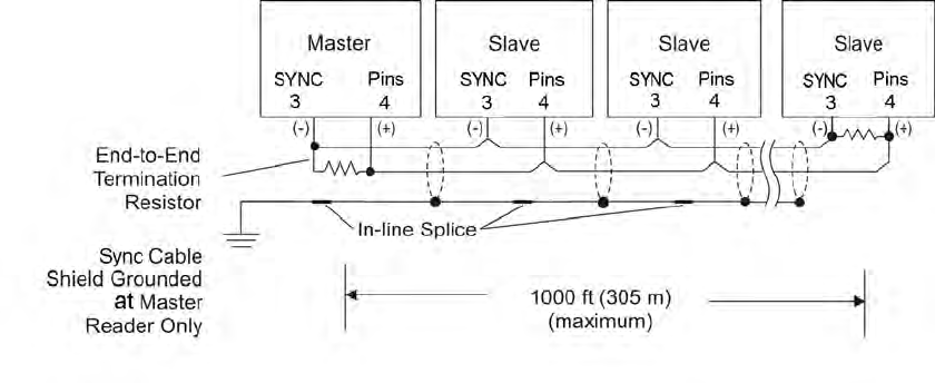
tion by connecting a pair of wires to the Sync pins on DB15 connector of each reader
as shown in Figure 3-3.
Figure 3-3 Sync Configuration Example
Star Systems recommends Belden 89182 (150 impedance), which is a single
twisted-pair shielded cable rated for outdoor use, or 8132 (120 impedance), which
is a double twisted-pair shielded cable that must be installed in conduit. The Belden
8132 cable has an extra pair that is not used. Using these low-loss, low-capacitance
twisted-pair cable, a distance of 1000 feet (305 m) has been obtained. Cables with
lower capacitance can be used to run the Sync cables for longer distances while main-
taining signal integrity. This maximum distance may be slightly longer or shorter
depending on the cable used.
Because the Sync signals are based on RS–485 signals, you can extend the length of
the Sync bus by using RS–485 repeaters or by using fiber with converters. The stan-
dard Sync interconnect is provided via pins 3 and 4 of the DB15 connector (Table 3-
1).
External Digital Input/Output Connector
The External Digital Input/Output Assembly is used to interface the Orion Reader
with external inputs and outputs. Inputs can be devices such as light curtains or loops,
and outputs can be devices such as gates or lights. (Connector is P/N 33357-01). This
option is described in detail in Appendix D, “Orion Reader Options.” The I/O Board is
pre-installed in the Orion Reader but I/O modules must be purchased separately.
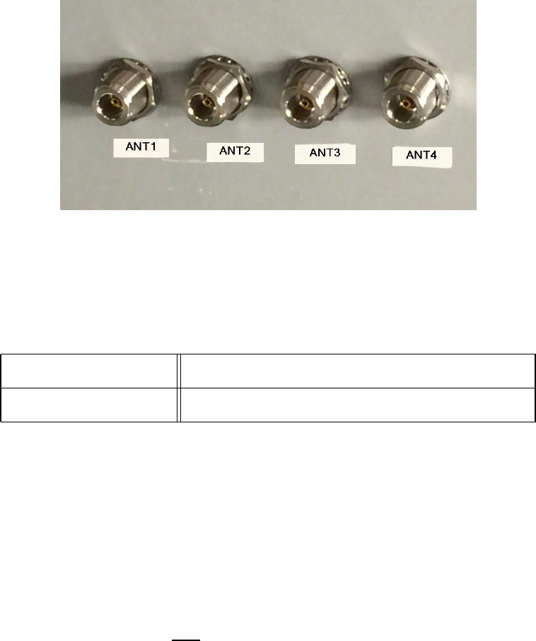
Connecting to Antenna
Connect the Orion Reader to a toll antenna using the single low-loss coaxial cable.
Figure 3-4 shows the antenna connectors on the Orion Reader enclosure. For a single-
Installing the Orion Reader
Use or disclosure of Proprietary Information contained on this sheet is subject to the restriction stated on the title page of this document. 3-9
antenna installation, where the transmit and receive data is communicated over a sin-
gle cable, use the connector labeled ANT1.
Figure 3-4 Antenna Connector Locations
Table 3-4 lists the RF antenna connector parameters.
Connecting to Host Computer
You can use TCP commands to operate the Orion Reader and communicate with the
host computer via the Ethernet port.
For TCP operation, the Orion Reader communicates with the host computer via the
Ethernet port. A single Orion Reader can be connected directly to a single host, which
is known as point-to-point connection. Multiple Orion Readers also can be connected
to a single host on a private local area network, or LAN.
In a multiple reader-to-host configuration, Star Systems recommends that the setup
has a dedicated network interface card (NIC) on the host that is then connected to an
Ethernet switch into which only the Orion Readers are connected.
Note: Do not connect any other device to that switch.
In this configuration the host would have another NIC that is connected to the main
network infrastructure to interact with the remainder of the toll system components.
The Ethernet switch should support 100 Mb/s full duplex operation to be fully com-
patible with the Orion Reader.
Ethernet Connector forTCP Communications
Table 3-4 RF Antenna Connector Specifications
Connector Type N-Type Female
Output Power Up to 2 watts

Orion Reader System Guide
3-10 Use or disclosure of Proprietary Information contained on this sheet is subject to the restriction stated on the title page of this document.
The Orion Reader communicates with a host via an Ethernet communications proto-
col. This connection requires an RJ–45 connector. If you connect the Orion Reader
directly to a host personal computer (PC) then you need a crossover cable. Star Sys-
tems recommends that you use Belden 7929A Category 5e twisted-pair cable for
Ethernet connections. Table 3-5 lists the Ethernet connector pin assignments.
Connecting to Additional System Components
Diagnostic Communications Connector (COM2)
The Orion Reader communicates diagnostic data via a serial communications protocol
(Table 3-6 and Table 3-7). The diagnostic port can be used to display the operating
system boot sequence, diagnostic, and error messages. By using the version command
(“Diagnostic Commands” on page 9-8), you can display data about the configuration
of the Orion Reader including its Internet Protocol (IP) address. Refer to “Communi-
cating Via Diagnostic Port (COM2)” on page 9-4 for complete diagnostic information.
Table 3-5 Ethernet Connector
Pin Signal Description 568Aa568Ba
1 TX+ Output Differential
Transmit Data (+) White w/ green stripe White w/ orange stripe
2 TX- Output Differential
Transmit Data (-) Green w/ white stripe or
solid green Orange w/ white stripe
or solid orange
3 RX+ Input Differential Receive
Data (+) White w/ orange stripe White w/ green stripe
4 Not connected N/A Blue w/ white stripe or
solid blue Blue w/ white stripe or
solid blue
5 Not connected N/A White w/ blue stripe White w/ blue stripe
6 RX- Input Differential Receive
Data (-) Orange w/ white stripe
or solid orange Green w/ white stripe or
solid green
7 Not connected N/A White w/ brown stripe
or solid brown White w/ brown stripe
8 Not connected N/A Brown w/ white stripe or
solid brown Brown w/ white stripe or
solid brown
a. 568A and 568B are Ethernet cable designations.
Table 3-6 RS–232 Serial Specifications
Connector Type 9-pin D-subminiature plug
Protocol RS–232
Baud 9600
Installing the Orion Reader
Use or disclosure of Proprietary Information contained on this sheet is subject to the restriction stated on the title page of this document. 3-11
Note: If you connect the Orion Reader COM2 port directly to a PC’s serial port, you
must use a null-modem serial cable or adapter.
Diagnostic Test Port Internal Connector
The Diagnostic Test Port Internal Connector is a 40-pin card-edge connector that
should be accessed by Star Systems factory-trained personnel only.
Global Positioning System Connector
The Global Positioning System (GPS) timing option is used when traditional Sync
cabling linking readers is not feasible. This option is described in detail in Appendix
D, “Orion Reader Options.”
Installing the Reader System Components
This section contains instructions for installing each component of the reader system.
You will need the following tools to install the system.
•Standard tools, such as Phillips and slotted screwdrivers, and wrenches
Bits 8
Parity None
Stop Bits 1
Flow Control None
Table 3-7 Diagnostic Communications Connector Parameters
Pin Signal Description
1 RSD Received line signal detect (not connected)
2 RXD Receive Data
3 TXD Transmit Data
4 DTR Data Terminal Ready (not connected)
5 GND Ground
6 DSR Data Set Ready (not connected)
7 RTS Request to Send
8 CTS Clear to Send
9 RI Ring indicator (not connected)
Table 3-6 RS–232 Serial Specifications (continued)

Orion Reader System Guide
3-12 Use or disclosure of Proprietary Information contained on this sheet is subject to the restriction stated on the title page of this document.
•Hydraulic lift or ladder for installing antennas
•Torque wrench for securing antenna connections
•Inclinometer or angle finder for measuring antenna angles
•Multimeter, Fluke 87 or equivalent for measuring electrical signals
Note: Chapter 9, “Configuring the Lane,” lists additional equipment required for
configuring lanes to optimize system performance.
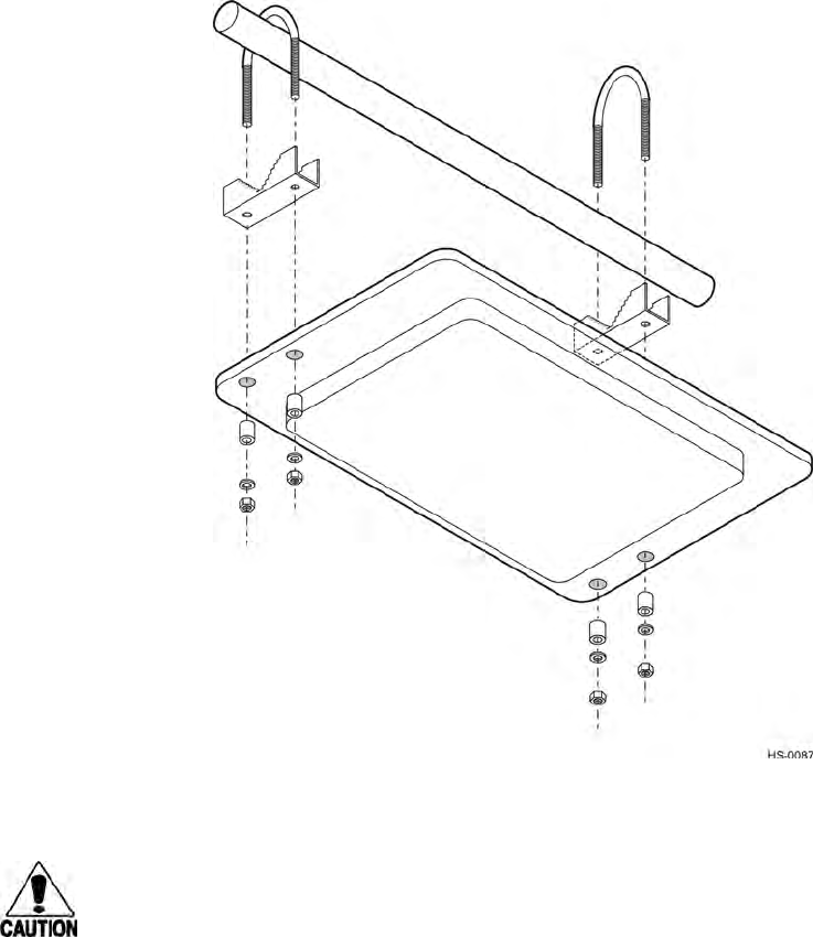
Mounting the Toll Antenna in an Overhead Location
For most overhead installations, the toll antenna is mounted on a 2- to 3-inch (5.0- to
7.6-cm) diameter pipe to accommodate various angles for lane configuring. Star Sys-
tems provides a mounting kit that includes the following hardware:
•Antenna
•Two U-bolts with hex nuts
•Two brackets
•Spacers
•Lock washers
•Fender washers (may not be included in your accessory kit)
•One 1.0-inch (2.5 cm) length of 1.1-inch (2.8-cm) diameter heat-shrink tubing
Installing the Orion Reader
Use or disclosure of Proprietary Information contained on this sheet is subject to the restriction stated on the title page of this document. 3-13
Figure 3-5 shows the standard way to mount and connect a toll antenna.
Figure 3-5 Toll Antenna Mounting and Connections
Caution
When installing the toll antenna use only the mounting hardware provided. Do not
use oversized washers to secure the plastic radome to the bracket. This practice can
weaken the radome material.
To install the toll antenna
1. Place the toll antenna below the mounting pipe and insert a U-bolt around the
pole and down through the bracket on the side of the antenna closest to the center
of the lane. This antenna should be mounted toward the driver side of the traffic
lane. Place a spacer, lock washer, and nut over each end of the U-bolt, but do not
tighten the nuts. Repeat for the other U-bolt.
2. Rotate the antenna up and toward oncoming traffic. Rotate up 15° from
horizontal for a lane. Use an inclinometer or angle finder to check the angle.
3. Tighten nuts with a torque wrench to 50 ft-lb (68 N-m).

Orion Reader System Guide
3-14 Use or disclosure of Proprietary Information contained on this sheet is subject to the restriction stated on the title page of this document.
4. Slide the shrink tubing over the coaxial cable, but do not heat it.
5. Connect the coaxial cable to the antenna and to the appropriate connector on the
Orion Reader. Leave the shrink tubing loose until you have finished configuring
the lane.
Starting the Orion Reader
Once the system components are in place, you need to connect them to the Orion
Reader, and power up and start the Orion Reader.
To start the Orion Reader
1. Connect coaxial cable from toll antenna to ANT 1 port on Orion Reader for a
single antenna configuration. Antenna ports 2-4 may also be used for systems
requiring multiple antennas.
2. Connect host PC or lane controller to Orion Reader using the Ethernet TCP
communications port (see Table 3-5.)
3. If using Sync to operate multiple lanes with Orion Reader, connect Sync cable to
pins 3 and 4 of the Power, Sync, and I/O Connector on the Orion Reader.
4. Connect other options as required. See Appendix D, “Orion Reader Options” for
detailed installation and operation information.
5. Connect the Orion Reader to 19V to 30V DC or 19V to 27V AC RMS @47-63
Hz power supply. See Figure 3-2 and Figure 3-3 for recommended wiring
directions.
Resetting the Orion Reader
If you need to restart the Orion Reader, the only information that is maintained by the
reader is the reader IP address, buffered tag data, and error logs. All other information
must be resent or reconfigured before the Orion Reader can be operated again.

4
General Software Information

General Software Information
Use or disclosure of Proprietary Information contained on this sheet is subject to the restriction stated on the title page of this document. 4-3
Chapter 4
General Software Information
This chapter provides transmission control protocol (TCP) information
for the Orion® Reader.
Software Information
This chapter presents various software-related topics arranged in alphabetical order by
subject. In addition to this chapter, refer to Chapter 5, “Communication Protocols,”
and Chapter 6, “Configuring and Operating the Orion Reader Using TCP Com-
mands,” for more information.
The Orion Reader operates using TCP commands. This chapter presents TCP com-
mand information.
TCP Command and Response Conventions
The Orion Reader implements TCP command requests, data acknowledgments, com-
mand responses, asynchronous responses, and unsolicited status messages as required
for configuration and operation. The messages are listed in Table 4-1.
Note: Throughout this chapter, host or host system refers to a host personal computer
(PC) or lane controller.
Table 4-1 TCP Command Messages
Message Description
Command request The host initiates and uses these messages to request the Orion Reader to perform
specific actions.
Data acknowledge The Orion Reader initiates and uses these messages to signal the reception of
command request messages received from the host. Additionally, the host initiates
and uses data acknowledge messages to signal the receipt of command response,
asynchronous response, and unsolicited status messages from the Orion Reader.
Command response The Orion Reader initiates these messages in response to specific command
request messages received from the host.
Asynchronous
response The Orion Reader optionally initiates these messages in response to specific
command request messages received from the host.
Unsolicited status The Orion Reader initiates and uses these messages to inform the host about
specific status conditions in the Orion Reader.
Orionl Reader System Guide
4-4 Use or disclosure of Proprietary Information contained on this sheet is subject to the restriction stated on the title page of this document.
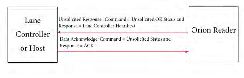
Lane Controller Heartbeat Controls
After the Lane Controller or host connects to the Orion Reader via TCP/IP, the Orion
Reader sends the LC Heartbeat message (unsolicited OK status message format) to the
Lane Controller or host every 10 seconds.
On receiving the LC Heartbeat message from the Orion Reader, the Lane Controller or
host sends the appropriate data acknowledge message to the Orion Reader. If the Lane
Controller or host does not acknowledge this message after three times, the Orion
Reader closes the connection. Figure 4-1 shows the Orion Reader LC heartbeat con-
trols in detail.
Figure 4-1 Orion Reader LC Heartbeat Controls
Sequence Number Controls
The Orion Reader implements message sequence numbers (MSN) and command
sequence numbers (CSN) in all of the message types (e.g., command request, data
acknowledge, command response, asynchronous response, and unsolicited status). All
transmitted messages, except for the data acknowledge message, increment the MSN
and CSN. The host and the Orion Reader must implement independent transmit and
receive counters for both the MSNs and the CSNs. The transmit counters are used in
generating the transmitted messages, and the receive counters are used in the received
message out-of-sequence error checking. An out-of-sequence error indicates that a
message was missed.
Note: CSNs are checked and generated by the reader for the System Interface
Command Group only. For all other command groups the reader ignores host-
generated CSNs, and the reader does not implement CSNs on any reader-generated
message. The host should ignore CSNs on all messages from the reader for all
command groups except for the System Interface Command Group.
With the exception of received data acknowledge messages, the Orion Reader per-
forms automatic MSN and CSN resynchronizations on all received messages that are
out-of-sequence. Upon receiving an out-of-sequence MSN, the Orion Reader sets the
receive MSN counter to the out-of-sequence MSN plus one. Similarly, upon receiving
an out-of-sequence CSN, the Orion Reader sets the receive CSN counter to the out-of-
sequence CSN plus one.
The host MSNs independently track the number of messages sent to the Orion Reader
General Software Information
Use or disclosure of Proprietary Information contained on this sheet is subject to the restriction stated on the title page of this document. 4-5
and the Orion Reader MSNs independently track the number of messages sent to the
host. These MSNs are used on the receiving end to determine if a message has been
missed.
The host CSNs for each command group independently track the number of command
request messages sent to the Orion Reader. The Orion Reader CSNs for each com-
mand group independently track the number of command response, asynchronous
response, and unsolicited status messages sent to the host. These CSNs are used on the
receiving end to determine if the appropriate message as specified above has been
missed.
The host and the Orion Reader use software communication sequence number con-
trols as defined in the following paragraphs.
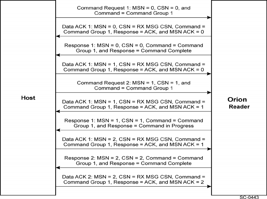
The Orion Reader sends data acknowledge, command response, asynchronous
response, and unsolicited status messages to the host with MSNs starting at zero and
incremented by one for each message sent, except for the data acknowledge message.
Additionally, the CSNs for each command group start at zero and are incremented by
one for each command response, asynchronous response, and unsolicited status mes-
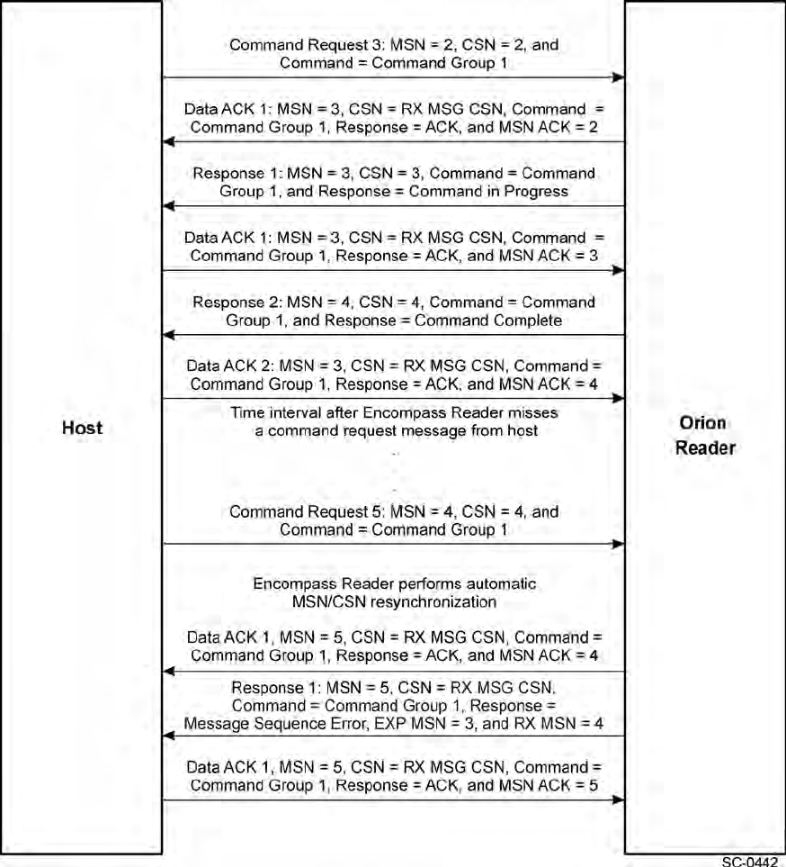
sage sent. Figure 4-2 and Figure 4-3 provide details on the sequence number controls.
The host receives data acknowledge, command response, asynchronous response, and
unsolicited status messages from the Orion Reader and checks that the MSNs and
CSNs are correct for all received message types except for the data acknowledge mes-
sage.
The Orion Reader receives command request messages and data acknowledge mes-
sages from the host and checks that the MSNs and CSNs are correct for all command
request messages received. The Orion Reader performs automatic MSN and CSN
resynchronizations on all received command request messages that are out-of-
sequence. Currently, the CSN resynchronizations are not fully supported.
If the Orion Reader detects either a message sequence error or command sequence
error, the Orion Reader sends the appropriate error message to the host that includes
the expected and received sequence numbers and then continues processing the
received message. Currently the message sequence error and command sequence error
messages are not fully supported.
Orionl Reader System Guide
4-6 Use or disclosure of Proprietary Information contained on this sheet is subject to the restriction stated on the title page of this document.
Figure 4-2 Orion Reader Sequence Number Controls
General Software Information
Use or disclosure of Proprietary Information contained on this sheet is subject to the restriction stated on the title page of this document. 4-7
Figure 4-3 Orion Reader Sequence Number Controls (cont’d.)
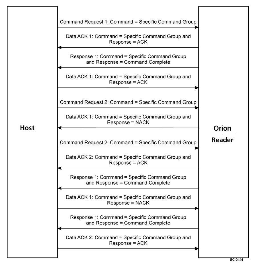
Data Acknowledge Controls
The Orion Reader initiates and uses data acknowledge messages to signal the recep-
tion of command request messages received from the host. Additionally, the host initi-
ates and uses data acknowledge messages to signal the receipt of command response,
asynchronous response, and unsolicited status messages from the Orion Reader.
Orionl Reader System Guide
4-8 Use or disclosure of Proprietary Information contained on this sheet is subject to the restriction stated on the title page of this document.
After receiving command request messages from the host, the Orion Reader sends
data acknowledge, command response, asynchronous response, and unsolicited status
messages to the host.
After receiving command response, asynchronous response, and unsolicited status
messages from the Orion Reader, the host sends data acknowledge messages to the
Orion Reader.
Use of Data Acknowledge Controls by Host and Orion Reader
The host and the Orion Reader use software communication data acknowledge con-
trols as defined here.
•The host sends command request messages to the Orion Reader.
•The host receives data acknowledge messages, or a data acknowledge time-out
occurs for each command request message sent to the Orion Reader.
•The host receives command response, asynchronous response, and unsolicited sta-
tus messages from the Orion Reader, and sends data acknowledge messages for
these message types.
•The Orion Reader receives command request messages from the host and sends
data acknowledge, command response, asynchronous response, and unsolicited
status messages to the host.
•The Orion Reader receives data acknowledge messages, or a data acknowledge
time-out occurs for each command response, asynchronous response, and unsolic-
ited status messages sent to the host.
For more details on the Orion Reader Data Acknowledge Controls, see Figure 4-4.
General Software Information
Use or disclosure of Proprietary Information contained on this sheet is subject to the restriction stated on the title page of this document. 4-9
Figure 4-4 Orion Reader Data Acknowledge Controls
Orionl Reader System Guide
4-10 Use or disclosure of Proprietary Information contained on this sheet is subject to the restriction stated on the title page of this document.

5
Communication Protocols

Communication Protocols
Use or disclosure of Proprietary Information contained on this sheet is subject to the restriction stated on the title page of this document. 5-3
Chapter 5
Communication Protocols
This chapter describes the transmission control protocol (TCP)
communications via Ethernet for the Orion® Reader.
Communication Between Orion Reader and Host
The Orion Reader can communicate with a host using TCP/IP Fast Ethernet commu-
nications protocol.
TCP/IP Fast Ethernet Connection
The Ethernet connector is an RJ-45 jack and uses a 100-base T interface. If the Orion
Reader is connected directly to the host system then a crossover cable is required.
Table 5-1 lists the Ethernet connector pin assignments.
Table 5-1 Ethernet Connector
Pin Signal Description 568Aa568Ba
1 TX+ Output Differential
Transmit Data (+) White w/ green stripe White w/ orange stripe
2 TX- Output Differential
Transmit Data (-) Green w/ white stripe or
solid green Orange w/ white stripe
or solid orange
3 RX+ Input Differential Receive
Data (+) White w/ orange stripe White w/ green stripe
4 Not connected N/A Blue w/ white stripe or
solid blue Blue w/ white stripe or
solid blue
5 Not connected N/A White w/ blue stripe White w/ blue stripe
6 RX- Input Differential Receive
Data (-) Orange w/ white stripe
or solid orange Green w/ white stripe or
solid green
7 Not connected N/A White w/ brown stripe
or solid brown White w/ brown stripe
8 Not connected N/A Brown w/ white stripe or
solid brown Brown w/ white stripe or
solid brown
a. 568A and 568B are Ethernet cable designations.
Orion Reader System Guide
5-4 Use or disclosure of Proprietary Information contained on this sheet is subject to the restriction stated on the title page of this document.
TCP/IP Fast Ethernet Communications Protocol
The TCP/IP Fast Ethernet communications protocol implements the TCP/IP Fast
Ethernet protocol. Table 5-2 lists the message parts.
Not all fields are used in each command message. The following sections provide spe-
cific message descriptions.
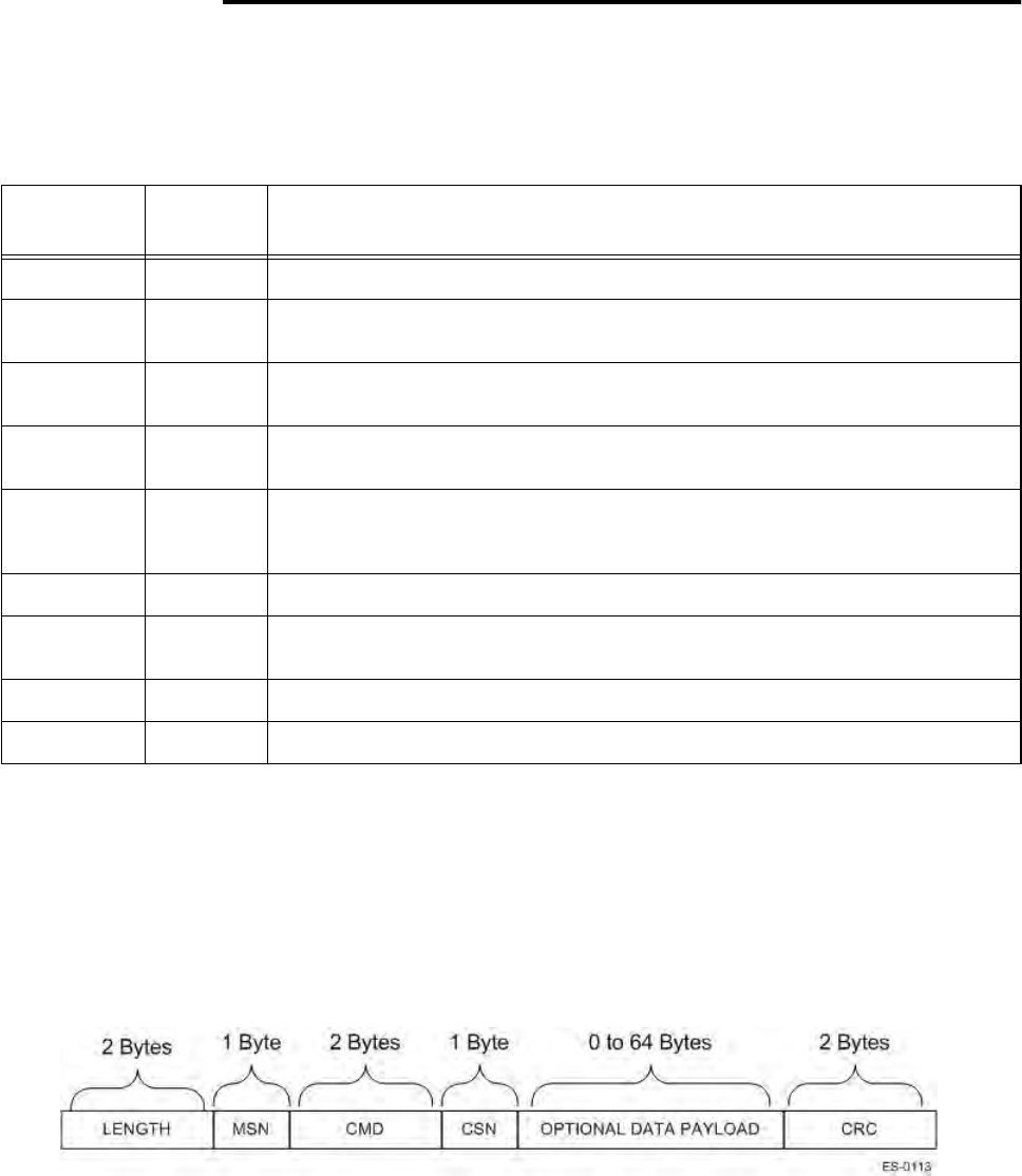
Command Request Message
The host sends command request messages to the Orion Reader as required for system
operation. The host and Orion Reader use the TCP/IP Fast Ethernet communications
command request message shown in Figure 5-1. Refer to Table 5-2 for message field
descriptions.
Figure 5-1 Command Request Message Fields
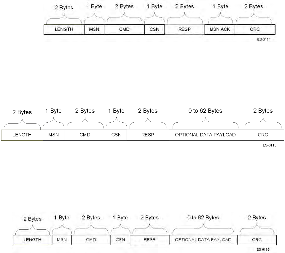
Table 5-2 TCP/IP Communications Message Field Descriptions
Field Length
(bytes) Description
LENGTH 2 Two-byte field specifying the number of bytes in the message.
MSN 1 One-byte field specifying the message sequence number of the message. See
the “Sequence Number Controls” section in Chapter 4 for details.
CMD 2 Two-byte field specifying the system command. See the “Command Request
Message” for details.
CSN 1 One-byte field specifying the command sequence number of the message.
See the “Sequence Number Controls” section in Chapter 4 for details.
OPTIONAL
DATA
PAYLOAD
Varies Optional data payload field varying in length from 0 to 64 bytes or 0 to 62 bytes
and specifies the data transmitted in message or data received in message.
CRC 2 Two-byte field specifying the cyclic redundancy check of the message.
RESP 2 Field specifying the system response and is typically two bytes. See the
response sections for details.
MSN ACK 1 One-byte field specifying the MSN of message being acknowledged.
STATUS 2 Field specifying the system status and is typically two bytes.
Communication Protocols
Use or disclosure of Proprietary Information contained on this sheet is subject to the restriction stated on the title page of this document. 5-5
Data Acknowledge Message
The host returns data acknowledge messages after receiving command response mes-
sages, asynchronous response messages, and unsolicited status messages. The host
and Orion Reader use the TCP/IP Fast Ethernet communications data acknowledge
message shown in Figure 5-2. Refer to Table 5-2 for message field descriptions.
Figure 5-2 Data Acknowledge Message Fields
Command Response Message
After receiving command request messages from the host, the Orion Reader returns
command response messages. The host and Orion Reader use the TCP/IP Fast Ether-
net communications command response message shown in Figure 5-3. Refer to Table
5-2 for message field descriptions.
Figure 5-3 Command Response Message Fields
Asynchronous Response Message
After receiving command request messages from the host, the Orion Reader option-
ally returns asynchronous response messages. The host and Orion Reader use the
TCP/IP Fast Ethernet communications asynchronous response message shown in .
Refer to Table 5-2 for message field descriptions.
Figure 5-4 Asynchronous Response Message Fields
Unsolicited Status Message
The Orion Reader sends unsolicited status messages as required for system operation.
The host and Orion Reader use the TCP/IP Fast Ethernet communications unsolicited
status message shown in Figure 5-5. Refer to Table 5-2 for message field descriptions.
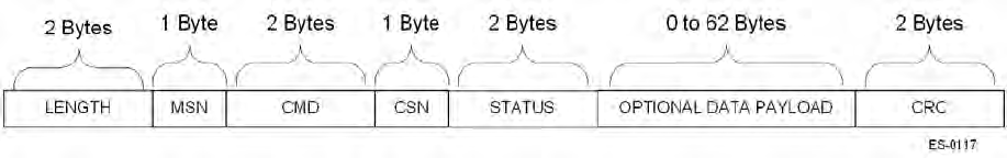
Orion Reader System Guide
5-6 Use or disclosure of Proprietary Information contained on this sheet is subject to the restriction stated on the title page of this document.
Figure 5-5 Unsolicited Status Message Fields

6
Configuring and Operating the Orion
Reader Using TCP Commands

Configuring and Operating the Orion Reader Using TCP Commands
Use or disclosure of Proprietary Information contained on this sheet is subject to the restriction stated on the title page of this document. 6-3
Chapter 6
Configuring and Operating the Orion Reader
Using TCP Commands
This chapter describes the Orion® Reader mode and commands that are
used to configure and operate the reader. This chapter also contains
system commands and responses that are needed to develop host
software for the TCP command set.
Chapter Organization
The Orion Reader is controlled through mode settings, which configure the reader for
specific applications. The Orion Reader starts in Mode 0, Stop Mode, and must be
changed to another mode as needed for a specific application.
This chapter first lists the operating mode to show what TCP-based command opera-
tions are available with this Orion Reader application.
The remainder of the chapter provides a complete listing of system commands and
responses that are required to develop host interface software for configuring the
Orion Reader. The system commands are divided into system command groups:
“System Interface Command Group Commands (8000H)” on page 6-13
“Digital I/O Command Group Commands (4000H)” on page 6-37
“RF Transceiver Command Group Commands (2000H)” on page 6-77
“Tag Transaction Configuration Command Group Commands (1000H)” on page 6-95
“Mode Command Group Commands (0400H)” on page 6-114
“Diagnostic Command Group Commands (0200H)” on page 6-127
Information for each of these command groups is grouped in the following manner:
•One table that lists the system command group commands
•One table that lists the system command group responses
•A series of tables that present system command group response data
•A full set of commands that are used to set an Orion Reader function and obtain
data resulting from that function within the specific system command group

Orion Reader System Guide
6-4 Use or disclosure of Proprietary Information contained on this sheet is subject to the restriction stated on the title page of this document.
Operating the Orion Reader in Mode 88
An Orion Reader operating in Mode 88 can read any combination of tag protocols
(ISO 18000-6C (EPC), Title 21, IAG or CVISN (ASTM Draft 6)) by using the Ether-
net port for transmission control protocol communications.
Caution
Where multiple tag protocols are used in the same installation, an Orion Reader
operating in Mode 88 is capable of reading any combination of the protocols; how-
ever, no more than two protocols should be used for high speed operations.
Working with Mode 88
The Orion Reader powers up in Mode 0, Stop Mode. You must issue the commands
(Table 6-1), via the host computer, to configure the reader.
Table 6-1 Commands Used to Configure Orion Reader in Mode 88
Sequence # Command Definition
1 Set Protocol(s)aThis command sets the protocols needed for a specific
application. The user can choose to set any number of protocols
in any combination.
2 Set Secondary Tag
SequenceaThis command specifies which state machine to run by selecting
the Title 21 tag protocol. The user must also set the
acknowledge (Ack) for Title 21, as well as the antenna number.
3 ResetaThis command resets the Orion Reader so that the previously
entered command(s) can take effect.
The following commands are required to configure Mode 88
4 If running a configuration
script, re-execute script at
this time.
Ensure that any changes made to protocols and secondary tag
sequences are reflected in the script file. Set the reader to Stop
Mode before executing the script file.
5 Set Frequency in MHz Sets the Orion Reader uplink and downlink frequencies. Reader
must be in Stop Mode.
6 Set Master/Slave This command specifies which Orion Reader is to be designated
as master, setting all other readers as slaves.
8 Set RF Attenuation This command sets the attenuation for a specific tag protocol.
9 Set Retry Count This command sets the number of times the Orion Reader
attempts to retry tag read. Some modes require that this
command is set more than once because of multiple tag
protocols. Note: the retry count for Title 21 is fixed.

Configuring and Operating the Orion Reader Using TCP Commands
Use or disclosure of Proprietary Information contained on this sheet is subject to the restriction stated on the title page of this document. 6-5
10 Set Data Detect This command sets the data detect value for a specific tag
protocol: ISO 18000-6C (EPC), Title 21, IAG, or CVISN. This
value is an independent detection threshold level for backscatter
protocols of up to 20dB. Data Detect can be incremented or
decremented in 1dB steps through the command interface port.
The threshold level for CVISN is 15 dB.
11 Set Seen Count and
Uniqueness Count This command sets a counter that records the number of times a
tag is read after the system had finished a complete transaction.
13 Set Time and Date This command sets the Orion Reader real-time clock to the time
and date specified in the request data.
14 Set Line Loss This command sets the Orion Reader system line loss value
from 0 to 3 decibels (dB) in 1-dB increments via the command
interface port. This command must be set only after RF
attenuation is set.
15 Set Manual Antenna
Channel This command sets the antenna channel.
16 Set Antenna Multiplexer
Configuration Data This command selects the antenna multiplexer mode.
18 Set IAG Slot This command sets the IAG trigger pulse slot, which allows
multiple readers to have non-overlapping IAG time slots.
19 Append Time-stamp This command is optional.
21 Set Mode This command sets the Orion Reader to Mode 88.
Set Protocol(s), Set Secondary Tag Sequence, and Reset commands must be transmitted in
the order shown in table.
Table 6-1 Commands Used to Configure Orion Reader in Mode 88
Sequence # Command Definition

Orion Reader System Guide
6-6 Use or disclosure of Proprietary Information contained on this sheet is subject to the restriction stated on the title page of this document.
System Commands
This section lists the Orion Reader system commands. Table 6-2 lists the system com-
mands, command groups, and command codes that are used with the Orion Reader.
Table 6-2 System Commands Used in Orion Reader
System Command Command
Code
System Interface (SI) Command Group 8000H
SI Command Group Data Acknowledge 8001H
Reserved 8002H
Reserved 8003H
Reserved 8004H
Reserved 8005H
Reserved 8008H
Reserved 8009H
SI Command Group Unsolicited Status 8010H
SI Command Group Unsolicited Status Data Acknowledge 8011H
Digital I/O Command Group 4000H
Digital I/O Command Group Data Acknowledge 4001H
Reserved 4002H
Reserved 4003H
Reserved 4004H
Reserved 4005H
Reserved 4008H
Reserved 4009H
Digital I/O Command Group Unsolicited Status 4010H
Digital I/O Command Group Unsolicited Status Data Acknowledge 4011H
RF Transceiver (RFT) Command Group 2000H
RFT Command Group Data Acknowledge 2001H

Configuring and Operating the Orion Reader Using TCP Commands
Use or disclosure of Proprietary Information contained on this sheet is subject to the restriction stated on the title page of this document. 6-7
Reserved 2002H
Reserved 2003H
Reserved 2004H
Reserved 2005H
Reserved 2008H
Reserved 2009H
RFT Command Group Unsolicited Status 2010H
RFT Command Group Unsolicited Status Data Acknowledge 2011H
Tag Transaction Configuration (TTC) Command Group 1000H
TTC Command Group Data Acknowledge 1001H
Reserved 1002H
Reserved 1003H
Reserved 1004H
Reserved 1005H
Reserved 1008H
Reserved 1009H
TTC Command Group Unsolicited Status 1010H
TTC Command Group Unsolicited Status Data Acknowledge 1011H
Tag Transaction (TT) Command Groupa0800H
TT Command Group Data Acknowledge 0801H
Reserved 0802H
Reserved 0803H
Reserved 0804H
Reserved 0805H
Reserved 0808H
Table 6-2 System Commands Used in Orion Reader
System Command Command
Code

Orion Reader System Guide
6-8 Use or disclosure of Proprietary Information contained on this sheet is subject to the restriction stated on the title page of this document.
Reserved 0809H
TT Command Group Unsolicited Status 0810H
TT Command Group Unsolicited Status Data Acknowledge 0811H
Mode Command Group 0400H
Mode Command Group Data Acknowledge 0401H
Reserved 0402H
Reserved 0403H
Reserved 0404H
Reserved 0405H
Reserved 0408H
Reserved 0409H
Mode Command Group Unsolicited Status 0410H
Mode Command Group Unsolicited Status Data Acknowledge 0411H
Diagnostic (Diag) Command Group 0200H
Diag Command Group Data Acknowledge 0201H
Reserved 0202H
Reserved 0203H
Reserved 0204H
Reserved 0205H
Reserved 0208H
Reserved 0209H
Diag Command Group Unsolicited Status 0210H
Diag Command Group Unsolicited Status Data Acknowledge 0211H
a. Tag Transaction Command Group commands and responses are discussed in detail in Chapter 8, “Tag
Responses.”
Table 6-2 System Commands Used in Orion Reader
System Command Command
Code

Configuring and Operating the Orion Reader Using TCP Commands
Use or disclosure of Proprietary Information contained on this sheet is subject to the restriction stated on the title page of this document. 6-9
Table 6-3 lists the bit definitions for the system commands.
Command Group Bit Fields
The host sets the appropriate command group bit fields in the system command when
sending command request and data acknowledge messages to the Orion Reader.
The Orion Reader sets the appropriate command group bit fields in the system com-
mand when sending data acknowledge, command response, asynchronous response,
and unsolicited status messages to the host.
Unsolicited Status Bit Field
The Orion Reader sets this bit field in the system command when sending unsolicited
status messages to the host.
Data Acknowledge Bit Field
Table 6-3 System Command Bit Definitions
Bit
Definition Description System
Command
Bit Code
Bit 15 System Interface Command Group Bit Field 8000H
Bit 14 Digital Input/Output (I/O) Command Group Bit Field 4000H
Bit 13 RF Transceiver Command Group Bit Field 2000H
Bit 12 Tag Transaction Configuration Command Group Bit Field 1000H
Bit 11 Reserved 0800H
Bit 10 Mode Command Group Bit Field 0400H
Bit 9 Diagnostic Command Group Bit Field 0200H
Bit 8 Reserved 0100H
Bit 7 Reserved 0080H
Bit 6 Reserved 0040H
Bit 5 Reserved 0020H
Bit 4 Unsolicited Status Bit Field 0010H
Bit 3 Reserved 0008H
Bit 2 Reserved 0004H
Bit 1 Reserved 0002H
Bit 0 Data Acknowledge Bit Field 0001H

Orion Reader System Guide
6-10 Use or disclosure of Proprietary Information contained on this sheet is subject to the restriction stated on the title page of this document.
The host sets this bit field in the system command when sending data acknowledge
messages to the Orion Reader. The Orion Reader sets this bit field in the system com-
mand when sending data acknowledge messages to the host.
Responses to System Commands
This section lists the responses to the Orion Reader system commands.
Responses and Codes for System Commands
Table 6-4 lists the response definitions and codes that are applicable to all system
commands.
Table 6-4 System Responses
System Response System Response
Code
Synchronous OK Status 88XXH
Asynchronous OK Status 48XXH
Unsolicited OK Status 28XXH
Reserved 84XXH
Reserved 44XXH
Reserved 24XXH
Synchronous Error Status 82XXH
Asynchronous Error Status 42XXH
Unsolicited Error Status 22XXH
Synchronous Control Status 81XXH
Asynchronous Control Status 41XXH
Unsolicited Control Status 21XXH

Configuring and Operating the Orion Reader Using TCP Commands
Use or disclosure of Proprietary Information contained on this sheet is subject to the restriction stated on the title page of this document. 6-11
Table 6-5 lists the bit definitions for the responses.
Synchronous Response Bit Field
The host sets this bit field in the system response when sending data acknowledge
messages to the Orion Reader. The Orion Reader sets this bit in the system response
when sending data acknowledge and command response messages to the host.
Asynchronous Response Bit Field
The Orion Reader sets this bit in the system response when sending asynchronous
response messages to the host.
Unsolicited Response Bit Field
The Orion Reader sets this bit in the system response when sending unsolicited status
messages to the host.
Table 6-5 System Command Response Bit Definitions
Bit
Definition Description System
Response
Bit Code
Bit 15 Synchronous Response Bit Field 8000H
Bit 14 Asynchronous Response Bit Field 4000H
Bit 13 Unsolicited Response Bit Field 2000H
Bit 12 Reserved 1000H
Bit 11 OK Status Bit Field 0800H
Bit 10 Reserved 0400H
Bit 9 Error Status Bit Field 0200H
Bit 8 Control Status Bit Field 0100H
Bit 7 Command Group Command Response Bit 7 0080H
Bit 6 Command Group Command Response Bit 6 0040H
Bit 5 Command Group Command Response Bit 5 0020H
Bit 4 Command Group Command Response Bit 4 0010H
Bit 3 Command Group Command Response Bit 3 0008H
Bit 2 Command Group Command Response Bit 2 0004H
Bit 1 Command Group Command Response Bit 1 0002H
Bit 0 Command Group Command Response Bit 0 0001H
Orion Reader System Guide
6-12 Use or disclosure of Proprietary Information contained on this sheet is subject to the restriction stated on the title page of this document.
OK Status Bit Field
The Orion Reader sets this bit field in the system response when the response is an OK
status.
Error Status Bit Field
The Orion Reader sets this bit field in the system response when the response is an
error status.
Control Status Bit Field
The host sets this bit field in the system response when sending data acknowledge
messages to the Orion Reader. The Orion Reader sets this bit field in the system
response when sending data acknowledge messages to the host.
Command Group Command Response Bit Fields
The host and the Orion Reader sets these bit fields in the system response to indicate
the command group command response. See the individual command group command
response sections for details.

Configuring and Operating the Orion Reader Using TCP Commands
Use or disclosure of Proprietary Information contained on this sheet is subject to the restriction stated on the title page of this document. 6-13
System Interface Command Group Commands (8000H)
The following sections detail the individual system command group commands and
responses. Refer to page 6-3 for an ordered list of the command groups.
Table 6-6 lists the System Interface Command Group commands that are used in the
Orion Reader.
Table 6-6 System Interface Command Group (8000H)
System Interface Commands Command
Code
System Identify 0000H
Set Time and Date 0003H
Get Time and Date 0004H
CPU App Firmware Download 0005H
Reset Reader 0006H
Get Buffered Tag Transaction 0007H
Get Number of Buffered Tag Transactions 0008H
Delete All Buffered Tag Transactions 0009H
Get System Startup Status 000AH
Get Lane Controller Interface Status 000BH
Get System Interface Status 000CH
Reserved 0011H
Reserved 0012H
Reserved 0013H
Reserved 0014H
Reserved 0015H
Set Buffered Tag Transaction Mode 0016H
Get Buffered Tag Transaction Mode 0017H
Set Data Acknowledge Time-out Period 0018H
Get Data Acknowledge Time-out Period 0019H
Set Switch Buffered Tag Transaction Mode Enable 001AH
Get Switch Buffered Tag Transaction Mode Enable 001BH

Orion Reader System Guide
6-14 Use or disclosure of Proprietary Information contained on this sheet is subject to the restriction stated on the title page of this document.
System Interface Command Group Responses
Table 6-7 lists the responses and codes for the system interface command group.
FPGA Firmware Download 001CH
CPU Boot Firmware Download 001DH
Reserved 001EH
Get System Serial Number 001FH
Get Firmware Version Numbers 0021H
Reserved 0022H to
0029H
Load Default Operating Parameters 002BH
Set Lane Controller/Host IP Address 0040H
Get Lane Controller/Host IP Address 0041H
Set IP Address and Subnet Mask 0042H
Get IP Address and Subnet Mask 0043H
Get TCP Port Number 0044H
Table 6-6 System Interface Command Group (8000H)
System Interface Commands Command
Code
Table 6-7 System Interface Command Group Responses
System Interface Response Response
Code
Synchronous OK Status Responses 88XXH
Reserved 8800H
Reserved 8801H
Asynchronous OK Status Responses 48XXH
Command Complete 4800H
Command In Progress 4801H
Firmware Download Active 4802H
Firmware Download Complete 4803H

Configuring and Operating the Orion Reader Using TCP Commands
Use or disclosure of Proprietary Information contained on this sheet is subject to the restriction stated on the title page of this document. 6-15
S-Record Processed 4804H
Unsolicited OK Status Responses 28XXH
LC Heartbeat 2811H
Reserved 84XXH
Reserved 44XXH
Reserved 24XXH
Synchronous Error Status Responses 82XXH
Message Length Error 8200H
Message Sequence Error 8201H
Reserved 8202H
Command Group Error 8203H
Reserved 8204H
Reserved 8205H
Reserved 8206H
Reserved 8207H
Reserved 8208H
Data Acknowledge Response Error 8209H
Reserved 820AH
Asynchronous Error Status Responses 42XXH
Message Length Error 4200H
Command Sequence Error 4201H
Table 6-7 System Interface Command Group Responses
System Interface Response Response
Code

Orion Reader System Guide
6-16 Use or disclosure of Proprietary Information contained on this sheet is subject to the restriction stated on the title page of this document.
System Interface Command Group Response Data
Asynchronous OK Status Responses
The following system interface command group asynchronous OK status responses
use the specified data payload.
Reserved 4202H
Command Group Error 4203H
Command Time-out Error 4204H
Reserved 4205H
Command Failed Error 4206H
System Command Error 4207H
Sub-command Error 4208H
Reserved 4209H
Invalid Control Word Error 420AH
Invalid Command Data Error 420BH
Erase Flash Error 420EH
Write Flash Error 420FH
Unsolicited Error Status Responses 22XXH
Synchronous Control Status Responses 81XXH
Data Acknowledge (Ack), data valid 8100H
Data Negative Acknowledge (Nack), data invalid 8101H
Reserved 8102H
Reserved 8104H
Asynchronous Control Status Responses 41XXH
Unsolicited Control Status Responses 21XXH
Table 6-7 System Interface Command Group Responses
System Interface Response Response
Code

Configuring and Operating the Orion Reader Using TCP Commands
Use or disclosure of Proprietary Information contained on this sheet is subject to the restriction stated on the title page of this document. 6-17
Command Complete (4800H)
Command In Progress (4801H)
Firmware Download Active System (4802H)
Firmware Download Complete System (4803H)
S-Record Processed System (4804H)
Synchronous Error Status Responses
The following system interface command group synchronous error status responses
use the specified data payload.
Command Complete Data Data
Payload
System Interface Command Group Command (sub-command) XXXXH
Command In Progress Response Data Data
Payload
System Interface Command Group Command (sub-command) XXXXH
Firmware Download Active Response Data Data
Payload
System Interface Command Group Command (sub-command) XXXXH
Firmware Download Complete Response Data Data
Payload
System Interface Command Group Command (sub-command) XXXXH
S-Record Processed Response Data Data
Payload
System Interface Command Group Command (sub-command) XXXXH

Orion Reader System Guide
6-18 Use or disclosure of Proprietary Information contained on this sheet is subject to the restriction stated on the title page of this document.
Message Length Error Response Data (8200H)
Message Sequence Error Response Data (8201H)
Command Group Error Response Data (8203H)
Data Acknowledge Response Error Response Data (8209H)
Asynchronous Error Status Responses
The following system interface command group asynchronous error status responses
use the specified data payload.
Message Length Error Response Data Data
Payload
Expected Message Length XXXXH
Received Message Length XXXXH
Message Sequence Error Response Data Data
Payload
Expected Message Sequence Number XXH
Received Message Sequence Number XXH
Command Group Error Response Data Data
Payload
Invalid Command Group XXXXH
Data Acknowledge Response Error Response Data Data
Payload
Invalid Data Acknowledge Response XXXXH

Configuring and Operating the Orion Reader Using TCP Commands
Use or disclosure of Proprietary Information contained on this sheet is subject to the restriction stated on the title page of this document. 6-19
Message Length Error Response Data (4200H)
Command Sequence Error Response Data (4201H)
Command Group Error (4203H)
Command Time-out Error (4204H)
Command Failed Error (4206H)
System Command Error (4207H)
Message Length Error Response Data Data
Payload
Expected Message Length XXXXH
Received Message Length XXXXH
Command Sequence Error Response Data Data
Payload
Expected Command Sequence Number XXH
Received Command Sequence Number XXH
Command Group Error Response Data Data
Payload
Invalid Command Group XXXXH
Command Time-out Error Response Data Data
Payload
N/A
Command Failed Error Response Data Data
Payload
System Interface Command Group Command (sub-command) XXXXH
System Command Error Response Data Data
Payload
N/A

Orion Reader System Guide
6-20 Use or disclosure of Proprietary Information contained on this sheet is subject to the restriction stated on the title page of this document.
Sub-Command Error (4208H)
Invalid Control Word Error (420AH)
Invalid Command Data Error (420BH)
Erase Flash Error System (420EH)
Write Flash Error System (420FH)
System Interface Command Group Unsolicited
Status Messages
The System Interface Command Group supports the generation of the following unso-
licited status messages as defined by the response code (Table 6-8).
Table 6-8 System Interface Command Group Unsolicited Status Messages
System Interface Command Group Unsolicited Status Messages Response
Code
LC Heartbeat message 2811H
Sub-Command Error Response Data Data
Payload
Sub-command XXXXH
Invalid Control Word Error Response Data Data
Payload
N/A
Invalid Command Data Error Response Data Data
Payload
N/A
Erase Flash Error Response Data Data
Payload
System Interface Command Group Command (sub-command) XXXXH
Write Flash Error Response Data Data
Payload
System Interface Command Group Command (sub-command) XXXXH
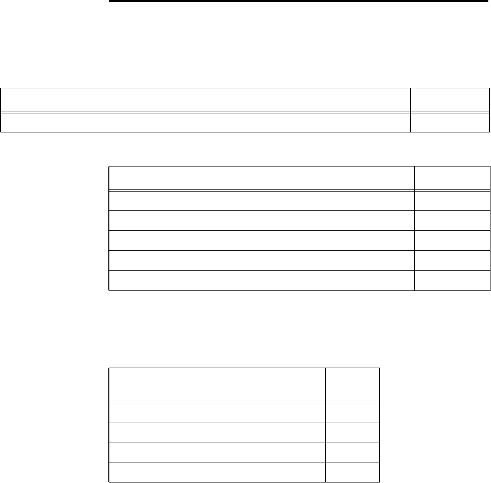
Configuring and Operating the Orion Reader Using TCP Commands
Use or disclosure of Proprietary Information contained on this sheet is subject to the restriction stated on the title page of this document. 6-21
System Identify
This command gets the reader’s system identify remote inventory. Table 6-9 and
Table 6-10 list the command and response data.
Each field’s data size is listed in Table 6-11.
Table 6-9 System Identify Command (0000H)
System Identify Command Data Data Payload
System Identify Command 0000H
Table 6-10 System Identify Response
System Identify Response Data Data Payload
System Identify Command 0000H
Vendor Name *
Version ID *
Part Number *
Serial Number *
*The information in this field is specific to each reader.
Table 6-11 System Identify Data
System Identify Data Data
Size
Vendor Name 15 bytes
Version ID 15 bytes
Part Number 15 bytes
Serial Number 15 bytes

Orion Reader System Guide
6-22 Use or disclosure of Proprietary Information contained on this sheet is subject to the restriction stated on the title page of this document.
Set Time and Date
The Set Time and Date command sets the Orion Reader real-time clock to the time
and date specified in the request data.
The data associated with the Set Time and Date defines the format of the time and date
(Table 6-12). You can modify and read this data at any time. This field is used with
the tag read parameters to append time and date to any response to the host system.
The Orion Reader has a battery-backed clock. Table 6-13 lists the response data.
Data Data Range
Hours 0 to 23 (00H to 17H)
Minutes 0 to 59 (00H to 3BH)
Seconds 0 to 59 (00H to 3BH)
Hundredths of seconds0 to 99 (00H to 63H)
Month 1 to 12 (01H to 0CH)
Day 1 to 31 (01H to 1FH)
Year 0 to 99 (00H to 63H)
Table 6-12 Set Time and Date Command (0003H)
Set Time and Data Command Data Data Payload
Set Time and Date Command 0003H
Hours XXH
Minutes XXH
Seconds XXH
Hundredths of Seconds XXH
Month XXH
Day XXH
Year XXH
Table 6-13 Set Time and Date Response
Set Time and Date Response Data Data Payload
Set Time and Date Response 0003H

Configuring and Operating the Orion Reader Using TCP Commands
Use or disclosure of Proprietary Information contained on this sheet is subject to the restriction stated on the title page of this document. 6-23
Get Time and Date
The Get Time and Date command requests the current time and date that is set on the
Orion Reader real-time clock. The data associated with the Get Time and Date defines
the format of the time and date (Table 6-14). You can modify and read this data at any
time. This field is used with the tag read parameters to append time and date to any
response to the host system. Table 6-15 lists the response data.
CPU App Firmware Download
This command downloads the reader’s CPU application firmware. Table 6-16 and
Table 6-17 list the command data and response.
Table 6-14 Get Time and Date Command (0004H)
Get Time and Date Command Data Data Payload
Get Time and Date Command 0004H
Table 6-15 Get Time and Date Response
Get Time and Date Response Data Data Payload
Get Time and Date Command 0004H
Hours XXH
Minutes XXH
Seconds XXH
Hundredths of Seconds XXH
Month XXH
Day XXH
Year XXH
Table 6-16 CPU App Firmware Download Command (0005H)
CPU App Firmware Download Command Data Data Payload
CPU App Firmware Download Command 0005H
Table 6-17 CPU App Firmware Download Response
CPU App Firmware Download Response Data Data Payload
CPU App Firmware Download Command 0005H
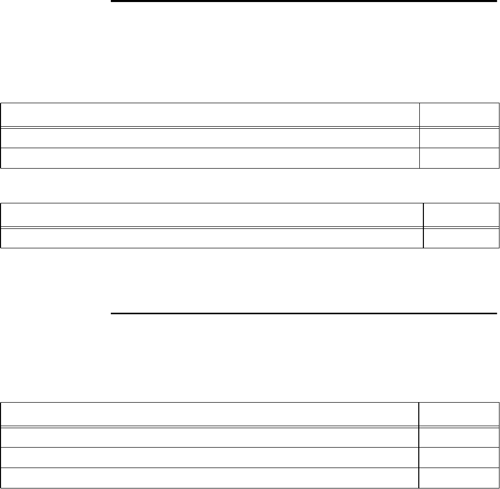
Orion Reader System Guide
6-24 Use or disclosure of Proprietary Information contained on this sheet is subject to the restriction stated on the title page of this document.
Reset Reader
The Reset Reader command initializes a power-up state (based on the nonvolatile set-
tings) of all of the Orion Reader parameters and starts the Orion Reader power-on
diagnostics. Table 6-18 and Table 6-19 list the command and response data.
When the Orion Reader is reset, the reader IP address, buffered tags, and error log are
maintained, all other information must be resent or reconfigured before the Orion
Reader can be operated again.
Get Buffered Tag Transaction
This command gets a specific buffered tag transaction from the reader. Table 6-20 and
Table 6-21 list the command and response data.
Table 6-18 Reset Reader Command (0006H)
Reset Reader Command Data Data Payload
Reset Reader Command 0006H
Reset Reader Control Word A5A5H
Table 6-19 Reset Reader Response
Reset Reader Response Data Data Payload
Reset Reader Command 0006H
Table 6-20 Get Buffered Tag Transaction Command (0007H)
Get Buffered Tag Transaction Command Data Data Payload
Get Buffered Tag Transaction Command 0007H
Buffered Tag Transaction Number (MSW) XXXXH
Buffered Tag Transaction Number (LSW) XXXXH

Configuring and Operating the Orion Reader Using TCP Commands
Use or disclosure of Proprietary Information contained on this sheet is subject to the restriction stated on the title page of this document. 6-25
The Buffered Tag Transaction Number field specifies the number of the buffered tag
transactions to be retrieved. The data values for this field range from 01H to
0FFFFFFFFH.
The Buffered Tag Transaction Data field contains the buffered tag transaction
response data that has a maximum byte length of 57.
Get Number of Buffered Tag Transactions
This command gets the number of buffered tag transactions that are stored in the
reader. Table 6-22 and Table 6-23 list the command and response data.
The buffered tag transaction overflow status is returned as 0 for no overflow or 1 for
overflow. The Number of Buffered Tag Transactions field specifies the current num-
ber of buffered tag transactions. The data values for this field range from 0H to
0FFFFFFFFH. Using the TCP command set, the Orion Reader can store up to
500,000 tag IDs in the buffer and the buffered tag information is saved upon reader
reset. The data values for this field range from 0H to 0FFFFFFFFH.
Table 6-21 Get Buffered Tag Transaction Response
Get Buffered Tag Transaction Response Data Data Payload
Get Buffered Tag Transaction Command 0007H
Buffered Tag Transaction Number (MSW) XXXXH
Buffered Tag Transaction Number (LSW) XXXXH
Buffered Tag Transaction Data
Table 6-22 Get Number of Buffered Tag Transactions Command (0008H)
Get Number of Buffered Tag Transactions Command Data Data Payload
Get Number of Buffered Tag Transactions Command 0008H
Table 6-23 Get Number of Buffered Tag Transactions Response Data
Get Number of Buffered Tag Transactions Response Data Data Payload
Get Number of Buffered Tag Transactions Command 0008H
Number of Buffered Tag Transactions (MSW) XXXXH
Number of Buffered Tag Transactions (LSW) XXXXH
Buffered Tag Transaction Overflow Status:0=nooverflow,1=overflow
XXH

Orion Reader System Guide
6-26 Use or disclosure of Proprietary Information contained on this sheet is subject to the restriction stated on the title page of this document.
Delete All Buffered Tag Transactions
This command deletes all buffered tag transactions stored in the reader. Table 6-24
and Table 6-25 list the command and response data.
Get System Startup Status
This command gets the Orion Reader system startup status. Table 6-26 and Table 6-27
list the command and response data.
Table 6-24 Delete All Buffered Tag Transactions Command (0009H)
Delete All Buffered Tag Transactions Command Data Data Payload
Delete All Buffered Tag Transactions Command 0009H
Delete All Buffered Tag Transactions Control Word A5A5H
Table 6-25 Delete All Buffered Tag Transactions Response
Delete All Buffered Tag Transactions Response Data Data Payload
Delete All Buffered Tag Transactions Command 0009H
Table 6-26 Get System Startup Status Command (000AH)
Get System Startup Status Command Data Data Payload
Get System Startup Status Command 000AH
Table 6-27 Get System Startup Status Response
Get System Startup Status Response Data Data Payload
Get System Startup Status Command 000AH
System Startup Module Number (System Initialization) XXXXH
System Timer Initialization Status Error Number XXXXH
System BMU Initialization Status Error Number XXXXH
System Queue Create Status Error Number XXXXH
System Task Create Status Error Number XXXXH

Configuring and Operating the Orion Reader Using TCP Commands
Use or disclosure of Proprietary Information contained on this sheet is subject to the restriction stated on the title page of this document. 6-27
Get Lane Controller Interface Status
This command gets the status of the reader’s lane controller interface software. Table
6-28 and Table 6-29 list the command and response data.
Get System Interface Status
This command gets the status of the reader’s system interface software. Table 6-30
and Table 6-31 list the command and response data.
Set Buffered Tag Transaction Mode
This command sets the buffered tag transaction mode in the reader. The mode control
byte can be set to 0 for real-time mode or 1 for buffered mode. Table 6-32 and Table
Table 6-28 Get Lane Controller Interface Status Command (000BH)
Get Lane Controller Interface Status Command Data Data Payload
Get Lane Controller Interface Status Command 000BH
Table 6-29 Get Lane Controller Interface Status Response
Get Lane Controller Interface Status Response Data Data Payload
Get Lane Controller Interface Status Command 000BH
Module Number XXXXH
Error Number XXXXH
Table 6-30 Get System Interface Status Command (000CH)
Get System Interface Status Command Data Data Payload
Get System Interface Status Command 000CH
Table 6-31 Get System Interface Status Response
Get System Interface Status Response Data Data Payload
Get System Interface Status Command 000CH
Module Number XXXXH
Error Number XXXXH

Orion Reader System Guide
6-28 Use or disclosure of Proprietary Information contained on this sheet is subject to the restriction stated on the title page of this document.
6-33 list the command and response data.
Get Buffered Tag Transaction Mode
This command gets the buffered tag transaction mode from the reader. The mode con-
trol byte is returned as 0 for real-time mode or 1 for buffered mode. Table 6-34 and
Table 6-35 list the command and response data.
Set Data Acknowledge Time-out Period
This command sets the reader’s data acknowledge time-out period in milliseconds.
Table 6-36 and Table 6-37 list the command and response data.
Table 6-32 Set Buffered Tag Transaction Mode Command (0016H)
Set Buffered Tag Transaction Mode Command Data Data Payload
Set Buffered Tag Transaction Command 0016H
Mode Control Byte: 0 = Real-Time Mode, 1 = Buffered Mode XXH
Table 6-33 Set Buffered Tag Transaction Mode Response
Set Buffered Tag Transaction Mode Response Data Data Payload
Set Buffered Tag Transaction Command 0016H
Table 6-34 Get Buffered Tag Transaction Mode Command (0017H)
Get Buffered Tag Transaction Mode Command Data Data Payload
Get Buffered Tag Transaction Command 0017H
Table 6-35 Get Buffered Tag Transaction Mode Response Data
Get Buffered Tag Transaction Mode Response Data Data Payload
Get Buffered Tag Transaction Command 0017H
Mode Control Byte: 0 = Real-Time Mode, 1 = Buffered Mode XXH
Table 6-36 Set Acknowledge Time-out Period Command (0018H)
Set Data Acknowledge Time-out Period Command Data Data Payload
Set Data Acknowledge Time-out Period Command 0018H
Communication Protocol XXH

Configuring and Operating the Orion Reader Using TCP Commands
Use or disclosure of Proprietary Information contained on this sheet is subject to the restriction stated on the title page of this document. 6-29
Communication Protocols
Table 6-38 lists the communication protocols that can be returned by the response.
Get Data Acknowledge Time-out Period
This command gets the data acknowledge time-out period from the reader. Table 6-39
and Table 6-40 list the command and response data.
Time-out Period in ms (MSB) XXH
Time-out Period in ms (LSB) XXH
Table 6-37 Set Acknowledge Time-out Period Response
Set Data Acknowledge Time-out Period Response Data Data Payload
Set Data Acknowledge Time-out Period Command 0018H
Communication Protocol XXH
Table 6-36 Set Acknowledge Time-out Period Command (0018H)
Table 6-38 Set Acknowledge Time-Out Period Communication Protocols
Communication Protocol Data Code
TCP/IP Communication 01H
Serial Communication 02H
Serial Debug Communication 03H
Table 6-39 Get Acknowledge Time-Out Period Command (0019H)
Get Data Acknowledge Time-out Period Command Data Data Payload
Get Data Acknowledge Time-out Period Command 0019H
Communication Protocol XXH
Table 6-40 Get Acknowledge Time-out Period Response Data
Get Data Acknowledge Time-out Period Response Data Data Payload
Get Data Acknowledge Time-out Period Command 0019H
Communication Protocol XXH
Time-out Period in ms (MSB) XXH

Orion Reader System Guide
6-30 Use or disclosure of Proprietary Information contained on this sheet is subject to the restriction stated on the title page of this document.
Table 6-41 lists the response protocols.
Set Switch Buffered Tag Transaction Mode Enable
This command sets the switch buffered tag transaction mode enable in the reader. The
enable control byte is returned as 0 for disabled or 1 for enabled. Table 6-42 and Table
6-43 list the command and response data.
Get Switch Buffered Tag Transaction Mode Enable
This command gets the switch buffered tag transaction mode enable from the reader.
The enable control byte is returned as 0 for disabled or 1 for enabled. Table 6-44 and
Table 6-45 list the command and response data.
Time-out Period in ms (LSB) XXH
Table 6-40 Get Acknowledge Time-out Period Response Data
Table 6-41 Get Acknowledge Time-out Period Communication Protocols
Communication Protocol Data Code
TCP/IP Communication 01H
Serial Communication 02H
Serial Debug Communication 03H
Table 6-42 Set Switch Buffered Tag Transaction Mode Enable Command (001AH)
Set Switch BufferedTag Transaction Mode Enable Command Data Data Payload
Set Switch Buffered Tag Transaction Mode Enable Command 001AH
Enable Control Byte: 0 = Disabled, 1 = Enabled XXH
Table 6-43 Set Switch Buffered Tag Transaction Mode Enable Response
Set Switch BufferedTag Transaction Mode Enable Response Data Data Payload
Set Switch Buffered Tag Transaction Mode Enable Command 001AH
Table 6-44 Get Switch Buffered Tag Transaction Mode Enable Command (001BH)
Get Switch BufferedTag Transaction Mode Enable Command Data
Data Payload
Get Switch Buffered Tag Transaction Mode Enable Command 001BH

Configuring and Operating the Orion Reader Using TCP Commands
Use or disclosure of Proprietary Information contained on this sheet is subject to the restriction stated on the title page of this document. 6-31
Table 6-45 Get Switch Buffered Tag Transaction Mode Enable Response
Get Switch BufferedTag Transaction Mode Enable Response Data
Data Payload
Get Switch Buffered Tag Transaction Mode Enable Command 001BH
Enable Control Byte: 0 = Disabled, 1 = Enabled XXH

Orion Reader System Guide
6-32 Use or disclosure of Proprietary Information contained on this sheet is subject to the restriction stated on the title page of this document.
FPGA Firmware Download
This command downloads the reader’s FPGA firmware. Table 6-46 and Table 6-47
list the command and response data.
CPU Boot Firmware Download
This command downloads the reader’s CPU boot firmware. Table 6-48 and Table 6-
49 list the command and response data.
Get System Serial Number
This command gets the reader’s serial number. Table 6-50 and Table 6-51 list the
command and response data.
Table 6-46 FPGA Firmware Download Command (001CH)
FPGA Firmware Download Command Data
Data Payload
FPGA Firmware Download Command 001CH
Table 6-47 FPGA Firmware Download Response
FPGA Firmware Download Response Data
Data Payload
FPGA Firmware Download Command 001CH
Table 6-48 CPU Boot Firmware Download Command (001DH)
CPU Boot Firmware Download Command Data
Data Payload
CPU Boot Firmware Download Command 001DH
Table 6-49 CPU Boot Firmware Download Response
CPU Boot Firmware Download Response Data
Data Payload
CPU Boot Firmware Download Command 001DH
Table 6-50 Get System Serial Number Command (001FH)
Get System Serial Number Command Data
Data Payload
Get System Serial Number Command 001FH

Configuring and Operating the Orion Reader Using TCP Commands
Use or disclosure of Proprietary Information contained on this sheet is subject to the restriction stated on the title page of this document. 6-33
Get Firmware Version Numbers
This command gets the reader’s firmware version numbers. Table 6-52 and Table 6-
53 list the command and response data.
Load Default Operating Parameters
Table 6-51 Get System Serial Number Response
Get System Serial Number Response Data
Data Payload
Get System Serial Number Command 001FH
Serial Number Data: 15 bytes
Table 6-52 Get Firmware Version Numbers Command (0021H)
Get Firmware Version Numbers Command Data Data Payload
Get Firmware Version Numbers Command 0021H
Table 6-53 Get Firmware Version Numbers Response
Get Firmware Version Numbers Response Data Data Payload
Get Firmware Version Numbers Command 0021H
Digital Board Central Processing Unit (CPU) Boot Firmware Version Number (MSW) XXXXH
Digital Board CPU Boot Firmware Version Number (LSW) XXXXH
Digital Board CPU Application Firmware Version Number (MSW) XXXXH
Digital Board CPU Application Firmware Version Number (LSW) XXXXH
Digital Board FPGA1 Firmware Version Number (MSW) XXXXH
Digital Board FPGA1 Firmware Version Number (LSW) XXXXH
Daughter Board FPGA2 Firmware Version Number (MSW) XXXXH
Daughter Board FPGA2 Firmware Version Number (LSW) XXXXH
RF Transceiver FPGA Firmware Version Number (MSW) XXXXH
RF Transceiver FPGA Firmware Version Number (LSW) XXXXH

Orion Reader System Guide
6-34 Use or disclosure of Proprietary Information contained on this sheet is subject to the restriction stated on the title page of this document.
This command loads the reader’s default operating parameters. Table 6-54 and Table
6-55 list the command and response data.
Set Lane Controller/Host IP Address
This command sets the reader’s lane controller/host IP address. Table 6-56 and Table
6-57 list the command and response data.
Get Lane Controller/Host IP Address
This command gets the reader’s lane controller/host IP address. Table 6-58 and Table
6-59 list the command and response data.
Table 6-54 Load Default Operating Parameters Command (002BH)
Load Default Operating Parameters Command Data Data Payload
Load Default Operating Parameters Command 002BH
Load Default Operating Parameters Control Word (MSB) A5H
Load Default Operating Parameters Control Word (LSB) A5H
Table 6-55 Load Default Operating Parameters Response
Load Default Operating Parameters Response Data Payload
Load Default Operating Parameters Command 002BH
Table 6-56 Set Lane Controller/Host IP Address Command (0040H)
Set Lane Controller/Host IP Address Command Data Data Payload
Set Lane Controller/Host IP Address Command 0040H
IP Address (MSW) XXXXH
IP Address (LSW) XXXXH
Table 6-57 Set Lane Controller/Host IP Address Response
Set Lane Controller/Host IP Address Response Data Data Payload
Set Lane Controller/Host IP Address Command 0040H

Configuring and Operating the Orion Reader Using TCP Commands
Use or disclosure of Proprietary Information contained on this sheet is subject to the restriction stated on the title page of this document. 6-35
Set IP Address and Subnet Mask
This command sets the reader’s IP address and subnet mask. Table 6-60 and Table 6-
61 list the command and response data.
Table 6-58 Get Lane Controller/Host IP Address Command (0041H)
Get Lane Controller/Host IP Address Command Data Data Payload
Get Lane Controller/Host IP Address Command 0041H
Table 6-59 Get Lane Controller/Host IP Address Response
Get Lane Controller/Host IP Address Response Data Data Payload
Get Lane Controller/Host IP Address Command 0041H
IP Address (MSW) XXXXH
IP Address (LSW) XXXXH
Table 6-60 Set IP Address and Subnet Mask Command (0042H)
Set IP Address and Subnet Mask Command Data Data Payload
Set IP Address and Subnet Mask Command 0042H
IP Address (MSW) XXXXH
IP Address (LSW) XXXXH
Subnet Mask (MSW) XXXXH
Subnet Mask (LSW) XXXXH
Table 6-61 Set IP Address and Subnet Mask Response
Set IP Address and Subnet Mask Response Data Data Payload
Set IP Address and Subnet Mask Command 0042H
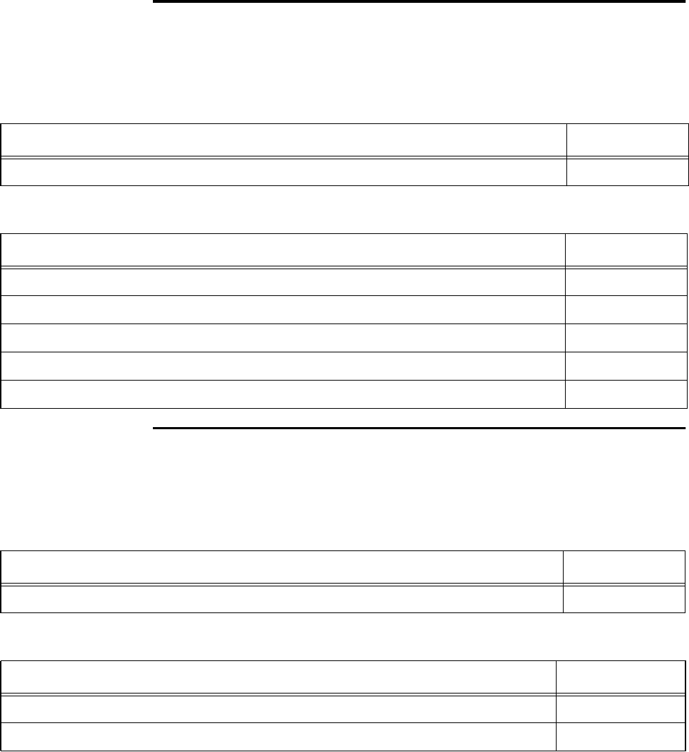
Orion Reader System Guide
6-36 Use or disclosure of Proprietary Information contained on this sheet is subject to the restriction stated on the title page of this document.
Get IP Address and Subnet Mask
This command gets the reader’s IP address and subnet mask. Table 6-62 and Table 6-
63 list the command and response data.
Get TCP Port Number
This command gets the reader’s TCP port number. Table 6-64 and Table 6-65 lists the
command and response data.
Table 6-62 Get IP Address and Subnet Mask Command (0043H)
Get IP Address and Subnet Mask Command Data Data Payload
Get IP Address and Subnet Mask Command 0043H
Table 6-63 Get IP Address and Subnet Mask Response
Get IP Address and Subnet Mask Response Data Data Payload
Get IP Address and Subnet Mask Command 0043H
IP Address (MSW) XXXXH
IP Address (LSW) XXXXH
Subnet Mask (MSW) XXXXH
Subnet Mask (LSW) XXXXH
Table 6-64 Get TCP Port Number Command (0044H)
Get TCP Port Number Command Data Data Payload
Get TCP Port Number Command 0044H
Table 6-65 Get TCP Port Number Response
Get TCP Port Number Response Data Data Payload
Get TCP Port Number Command 0044H
Port Number XXXXH

Configuring and Operating the Orion Reader Using TCP Commands
Use or disclosure of Proprietary Information contained on this sheet is subject to the restriction stated on the title page of this document. 6-37
Digital I/O Command Group Commands (4000H)
The digital input/output (I/O) assembly is used to interface the Orion Reader with
external inputs and outputs. Inputs can be devices such as light curtains or loops, and
outputs can be devices such as gates or lights. Table 6-66 lists the Digital I/O Com-
mand Group commands that are used in the Orion multiprotocol reader.
Table 6-66 Digital I/O Command Group Commands
Digital I/O Configuration Command Command
Code
Set Digital I/O Sensor Status Change Report 0000H
Get Digital I/O Sensor Status Change Report 0001H
Set Digital I/O Output Host Control 0002H
Get Digital I/O Output Host Control 0003H
Set Digital I/O Output Tag Read Control 0004H
Get Digital I/O Output Tag Read Control 0005H
Set Digital I/O RF Control 0006H
Get Digital I/O RF Control 0007H
Set Digital I/O RF Multiplexing Mode 0008H
Get Digital I/O RF Multiplexing Mode 0009H
Set Digital I/O Output Pulse Duration 000AH
Get Digital I/O Output Pulse Duration 000BH
Set Digital I/O Minimum Presence True Period 000CH
Get Digital I/O Minimum Presence True Period 000DH
Set Digital I/O Sensor Input Inversion 000EH
Get Digital I/O Sensor Input Inversion 000FH
Set Digital I/O Port Configuration 0010H
Get Digital I/O Port Configuration 0011H
Set Digital I/O Sensor Input Report 0012H
Get Digital I/O Sensor Input Report 0013H
Set Digital I/O Presence RF Control Algorithm 0014H
Get Digital I/O Presence RF Control Algorithm 0015H

Orion Reader System Guide
6-38 Use or disclosure of Proprietary Information contained on this sheet is subject to the restriction stated on the title page of this document.
Digital I/O Command Group Responses
Table 6-67 lists the responses and codes for the Digital I/O command group.
Set Digital I/O Presence RF Control Time-Out Period 0016H
Get Digital I/O Presence RF Control Time-Out Period 0017H
Get Digital I/O Port Status 0018H
Set Digital I/O Mode 0019H
Get Digital I/O Mode 001AH
Set External Interrupt Control 056DH
Get External Interrupt Control 06ADH
Table 6-67 Digital I/O Command Group Responses
Digital I/O Responses Response
Code
Synchronous OK Status Responses 88XXH
Reserved 8800H
Reserved 8801H
Asynchronous OK Status Responses 48XXH
Command Complete 4800H
Command In Progress 4801H
Unsolicited OK Status Responses 28XXH
Reserved 84XXH
Reserved 44XXH
Table 6-66 Digital I/O Command Group Commands
Digital I/O Configuration Command Command
Code

Configuring and Operating the Orion Reader Using TCP Commands
Use or disclosure of Proprietary Information contained on this sheet is subject to the restriction stated on the title page of this document. 6-39
Reserved 24XXH
Synchronous Error Status Responses 82XXH
Message Length Error 8200H
Message Sequence Error 8201H
Reserved 8202H
Command Group Error 8203H
Reserved 8204H
Reserved 8205H
Reserved 8206H
Reserved 8207H
Reserved 8208H
Data Acknowledge Response Error 8209H
Reserved 820AH
Asynchronous Error Status Responses 42XXH
Message Length Error 4200H
Command Sequence Error 4201H
Reserved 4202H
Command Group Error 4203H
Command Time-out Error 4204H
Reserved 4205H
Command Failed Error 4206H
System Command Error 4207H
Sub-command Error 4208H
Reserved 4209H
Invalid Control Word Error 420AH
Table 6-67 Digital I/O Command Group Responses
Digital I/O Responses Response
Code

Orion Reader System Guide
6-40 Use or disclosure of Proprietary Information contained on this sheet is subject to the restriction stated on the title page of this document.
Digital I/O Command Group Response Data
Asynchronous OK Status Responses
The following Digital I/O command group asynchronous OK status responses use the
specified data payload.
Command Complete (4800H)
Command In Progress (4801H)
Synchronous Error Status Responses
The following Digital I/O command group synchronous error status responses use the
specified data payload.
Invalid Command Data Error System 420BH
Unsolicited Error Status Responses 22XXH
Synchronous Control Status Responses 81XXH
Data Acknowledge (Ack), data valid 8100H
Data Negative Acknowledge (Nack), data invalid 8101H
Reserved 8102H
Reserved 8104H
Asynchronous Control Status Responses 41XXH
Unsolicited Control Status Responses 21XXH
Command In Progress Response Data Data
Payload
Digital I/O Command Group Command (sub-command) XXXXH
Command In Progress Response Data Data
Payload
Digital I/O Command Group Command (sub-command) XXXXH
Table 6-67 Digital I/O Command Group Responses
Digital I/O Responses Response
Code

Configuring and Operating the Orion Reader Using TCP Commands
Use or disclosure of Proprietary Information contained on this sheet is subject to the restriction stated on the title page of this document. 6-41
Message Length Error Response Data (8200H)
Message Sequence Error Response Data (8201H)
Command Group Error Response Data (8203H)
Data Acknowledge Response Error Response Data (8209H)
Asynchronous Error Status Responses
The following Digital I/O command group asynchronous error status responses use
the specified data payload.
Message Length Error Response Data Data
Payload
Expected Message Length XXXXH
Received Message Length XXXXH
Message Sequence Error Response Data Data
Payload
Expected Message Sequence Number XXH
Received Message Sequence Number XXH
Command Group Error Response Data Data
Payload
Invalid Command Group XXXXH
Data Acknowledge Response Error Response Data Data
Payload
Invalid Data Acknowledge Response XXXXH

Orion Reader System Guide
6-42 Use or disclosure of Proprietary Information contained on this sheet is subject to the restriction stated on the title page of this document.
Message Length Error Response Data (4200H)
Command Sequence Error Response Data (4201H)
Command Group Error (4203H)
Command Time-out Error (4204H)
Command Failed Error (4206H)
System Command Error (4207H)
Message Length Error Response Data Data
Payload
Expected Message Length XXXXH
Received Message Length XXXXH
Command Sequence Error Response Data Data
Payload
Expected Command Sequence Number XXH
Received Command Sequence Number XXH
Command Group Error Response Data Data
Payload
Invalid Command Group XXXXH
Command Time-out Error Response Data Data
Payload
N/A
Command Failed Error Response Data Data
Payload
Digital I/O Command Group Command (sub-command) XXXXH
System Command Error Response Data Data
Payload
N/A
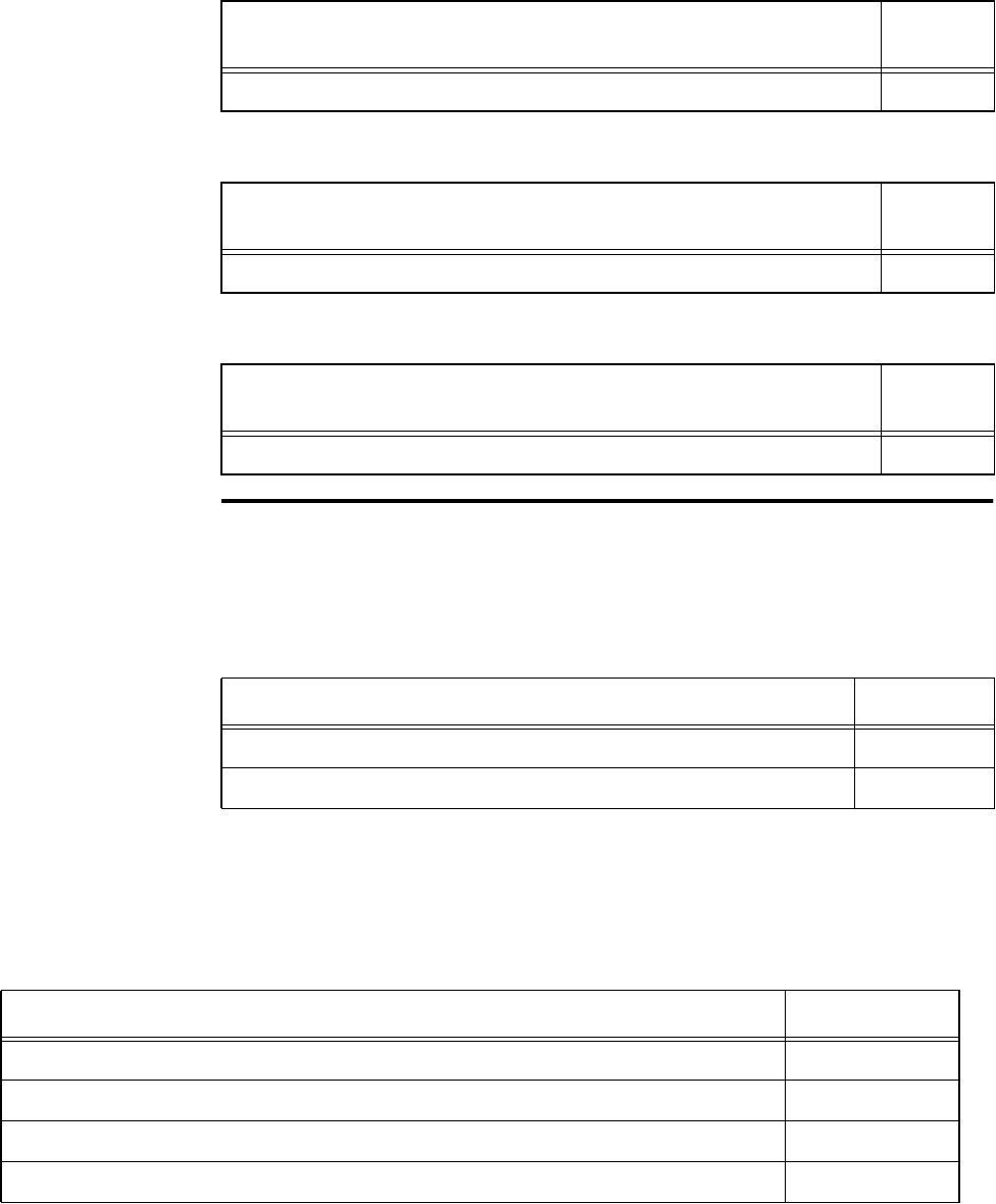
Configuring and Operating the Orion Reader Using TCP Commands
Use or disclosure of Proprietary Information contained on this sheet is subject to the restriction stated on the title page of this document. 6-43
Sub-Command Error (4208H)
Invalid Control Word Error (420AH)
Invalid Command Data Error (420BH)
Digital I/O Asynchronous Reports
The Digital I/O supports the generation of the following asynchronous response mes-
sage reports as defined by the transaction record type code (Table 6-68).
Sensor Status Change Report
This Digital I/O report is generated when a sensor detects a presence change and that
sensor is configured to generate a report (Table 6-69).
Sub-Command Error Response Data Data
Payload
Sub-command XXXXH
Invalid Control Word Error Response Data Data
Payload
N/A
Invalid Command Data Error Response Data Data
Payload
N/A
Table 6-68 Digital I/O Asynchronous Reports
Digital I/O Asynchronous Report Type Code
Sensor Status Change Report 3050H
Sensor Input Report 3051H
Table 6-69 Sensor Status Change Report
Sensor Status Change Report Data Payload
Sensor Status Change Report Transaction Record Type 3050H
Port Configuration 0XH
Port number Reporting Status Change: 0–3 for Port0–Port 3 0XH
Port Status 0XH

Orion Reader System Guide
6-44 Use or disclosure of Proprietary Information contained on this sheet is subject to the restriction stated on the title page of this document.
Port Configuration — This field specifies the digital port input/output configuration.
In Table 6-70, INPUT = 0 and OUTPUT = 1.
Port Status — This field specifies the digital port status. In Table 6-71, LOW = 0 and
HIGH = 1.
Table 6-70 Port Configuration
Configuration
Value Digital Port 3 Digital Port 2 Digital Port 1 Digital Port 0
00H INPUT INPUT INPUT INPUT
01H INPUT INPUT INPUT OUTPUT
02H INPUT INPUT OUTPUT INPUT
03H INPUT INPUT OUTPUT OUTPUT
04H INPUT OUTPUT INPUT INPUT
05H INPUT OUTPUT INPUT OUTPUT
06H INPUT OUTPUT OUTPUT INPUT
07H INPUT OUTPUT OUTPUT OUTPUT
08H OUTPUT INPUT INPUT INPUT
09H OUTPUT INPUT INPUT OUTPUT
0AH OUTPUT INPUT OUTPUT INPUT
0BH OUTPUT INPUT OUTPUT OUTPUT
0CH OUTPUT OUTPUT INPUT INPUT
0DH OUTPUT OUTPUT INPUT OUTPUT
0EH OUTPUT OUTPUT OUTPUT INPUT
0FH OUTPUT OUTPUT OUTPUT OUTPUT
Table 6-71 Port Status
Status Value Digital Port 3 Digital Port 2 Digital Port 1 Digital Port 0
00H LOW LOW LOW LOW
01H LOW LOW LOW HIGH
02H LOW LOW HIGH LOW
03H LOW LOW HIGH HIGH
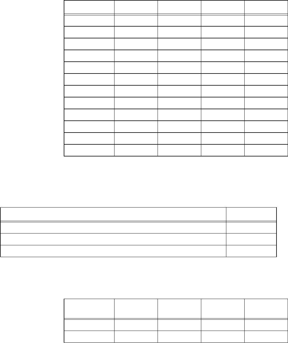
Configuring and Operating the Orion Reader Using TCP Commands
Use or disclosure of Proprietary Information contained on this sheet is subject to the restriction stated on the title page of this document. 6-45
Sensor Input Report
This digital I/O report generates when a sensor detects a vehicle presence but no valid
tag read occurs (Table 6-72).
Port Configuration — This field specifies the digital port input/output configuration.
In Table 6-73, INPUT = 0 and OUTPUT = 1.
04H LOW HIGH LOW LOW
05H LOW HIGH LOW HIGH
06H LOW HIGH HIGH LOW
07H LOW HIGH HIGH HIGH
08H HIGH LOW LOW LOW
09H HIGH LOW LOW HIGH
0AH HIGH LOW HIGH LOW
0BH HIGH LOW HIGH HIGH
0CH HIGH HIGH LOW LOW
0DH HIGH HIGH LOW HIGH
0EH HIGH HIGH HIGH LOW
0FH HIGH HIGH HIGH HIGH
Table 6-71 Port Status
Status Value Digital Port 3 Digital Port 2 Digital Port 1 Digital Port 0
Table 6-72 Sensor Input Report
Sensor Input Report Data Payload
Sensor Input Report Transaction Record Type 3051H
Port Configuration 0XH
Port Number Reporting Missed Tag Read: 0–3 for Port0–Port3 0XH
Table 6-73 Port Configuration
Configuration
Value Digital Port 3 Digital Port 2 Digital Port 1 Digital Port 0
00H INPUT INPUT INPUT INPUT
01H INPUT INPUT INPUT OUTPUT
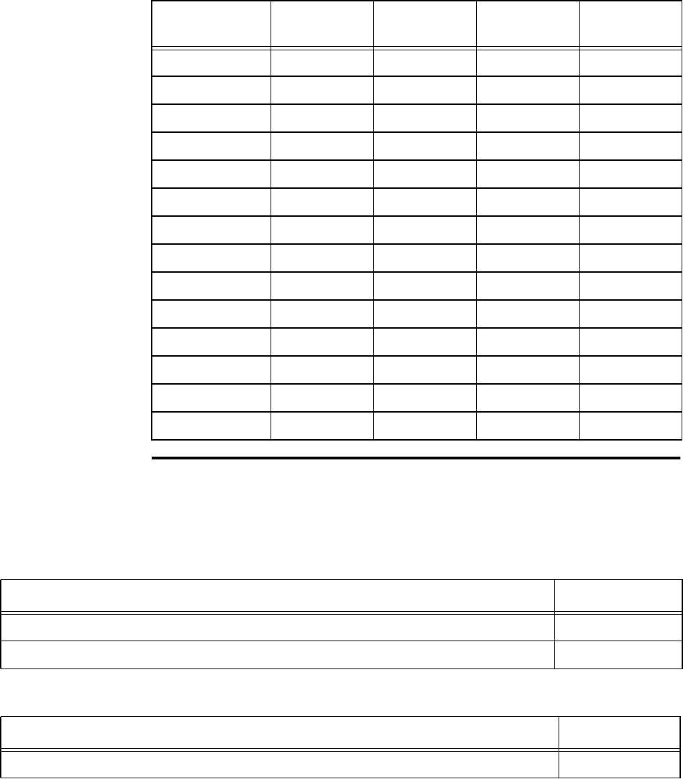
Orion Reader System Guide
6-46 Use or disclosure of Proprietary Information contained on this sheet is subject to the restriction stated on the title page of this document.
Set Digital I/O Sensor Status Change Report
This command sets the digital I/O sensor status change report mask. Table 6-74 and
Table 6-75 list the command and response data.
02H INPUT INPUT OUTPUT INPUT
03H INPUT INPUT OUTPUT OUTPUT
04H INPUT OUTPUT INPUT INPUT
05H INPUT OUTPUT INPUT OUTPUT
06H INPUT OUTPUT OUTPUT INPUT
07H INPUT OUTPUT OUTPUT OUTPUT
08H OUTPUT INPUT INPUT INPUT
09H OUTPUT INPUT INPUT OUTPUT
0AH OUTPUT INPUT OUTPUT INPUT
0BH OUTPUT INPUT OUTPUT OUTPUT
0CH OUTPUT OUTPUT INPUT INPUT
0DH OUTPUT OUTPUT INPUT OUTPUT
0EH OUTPUT OUTPUT OUTPUT INPUT
0FH OUTPUT OUTPUT OUTPUT OUTPUT
Table 6-73 Port Configuration
Configuration
Value Digital Port 3 Digital Port 2 Digital Port 1 Digital Port 0
Table 6-74 Set Digital I/O Sensor Status Change Report Command (0000H)
Set Digital I/O Sensor Status Change Report Data Data Payload
Set Digital I/O Sensor Status Change Report 0000H
Sensor Status Change Report Mask 0XH
Table 6-75 Set Digital I/O Sensor Status Change Report Response
Set Digital I/O Sensor Status Change Report Response Data Data Payload
Set Digital I/O Sensor Status Change Report Command 0000H
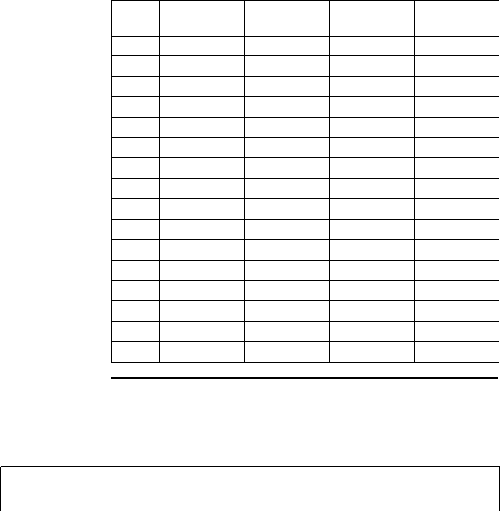
Configuring and Operating the Orion Reader Using TCP Commands
Use or disclosure of Proprietary Information contained on this sheet is subject to the restriction stated on the title page of this document. 6-47
Sensor Status Change Report Mask — This field specifies the sensor inputs that are
monitored for status change and associated sensor status change report generation. In
Table 6-76, OFF = 0 and ON = 1.
Get Digital I/O Sensor Status Change Report
This command gets the digital I/O sensor status change report mask. Table 6-77 and
Table 6-78 list the command and response data.
Table 6-76 Sensor Status Change Report Mask Values
Mask
Value Sensor Input 3 Sensor Input 2 Sensor Input 1 Sensor Input 0
00H OFF OFF OFF OFF
01H OFF OFF OFF ON
02H OFF OFF ON OFF
03H OFF OFF ON ON
04H OFF ON OFF OFF
05H OFF ON OFF ON
06H OFF ON ON OFF
07H OFF ON ON ON
08H ON OFF OFF OFF
09H ON OFF OFF ON
0AH ON OFF ON OFF
0BH ON OFF ON ON
0CH ON ON OFF OFF
0DH ON ON OFF ON
0EH ON ON ON OFF
0FH ON ON ON ON
Table 6-77 Get Digital I/O Sensor Status Change Report Command (0001H)
Get Digital I/O Sensor Status Change Report Data Data Payload
Get Digital I/O Sensor Status Change Report 0001H
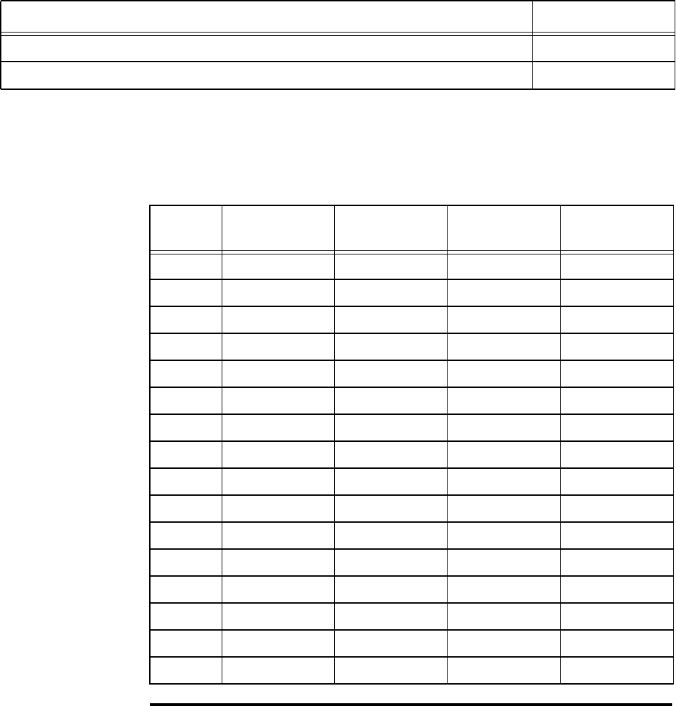
Orion Reader System Guide
6-48 Use or disclosure of Proprietary Information contained on this sheet is subject to the restriction stated on the title page of this document.
Sensor Status Change Report Mask — This field specifies the sensor inputs that are
monitored for status change and associated sensor status change report generation. In
Table 6-79, OFF = 0 and ON = 1.
Set Digital I/O Output Host Control
Table 6-78 Get Digital I/O Sensor Status Change Report Response
Get Digital I/O Sensor Status Change Report Response Data Data Payload
Get Digital I/O Sensor Status Change Report Command 0001H
Sensor Status Change Report Mask 0XH
Table 6-79 Sensor Status Change Report Mask Values
Mask
Value Sensor Input 3 Sensor Input 2 Sensor Input 1 Sensor Input 0
00H OFF OFF OFF OFF
01H OFF OFF OFF ON
02H OFF OFF ON OFF
03H OFF OFF ON ON
04H OFF ON OFF OFF
05H OFF ON OFF ON
06H OFF ON ON OFF
07H OFF ON ON ON
08H ON OFF OFF OFF
09H ON OFF OFF ON
0AH ON OFF ON OFF
0BH ON OFF ON ON
0CH ON ON OFF OFF
0DH ON ON OFF ON
0EH ON ON ON OFF
0FH ON ON ON ON
Configuring and Operating the Orion Reader Using TCP Commands
Use or disclosure of Proprietary Information contained on this sheet is subject to the restriction stated on the title page of this document. 6-49
This command sets the digital I/O outputs that the host controls. Table 6-80 and Table
6-81 list the command and response data.
Output Control — This field specifies the digital outputs that the host controls. In
Table 6-82, OFF = 0 and ON = 1.
Table 6-80 Set Digital I/O Output Host Control Command (0002H)
Set Digital I/O Output Host Control Data Data Payload
Set Digital I/O Output Host Control Command 0002H
Output Control 0XH
Table 6-81 Set Digital I/O Output Host Control Response
Set Digital I/O Output Host Control Response Data Data Payload
Set Digital I/O Output Host Control Command 0002H
Table 6-82 Output Control Values
Control
Value Output
Control 3 Output
Control 2 Output
Control 1 Output
Control 0
00H OFF OFF OFF OFF
01H OFF OFF OFF ON
02H OFF OFF ON OFF
03H OFF OFF ON ON
04H OFF ON OFF OFF
05H OFF ON OFF ON
06H OFF ON ON OFF
07H OFF ON ON ON
08H ON OFF OFF OFF
09H ON OFF OFF ON
0AH ON OFF ON OFF
0BH ON OFF ON ON
0CH ON ON OFF OFF
0DH ON ON OFF ON
0EH ON ON ON OFF

Orion Reader System Guide
6-50 Use or disclosure of Proprietary Information contained on this sheet is subject to the restriction stated on the title page of this document.
Note: RESET READER command required to set output host control, but not required
if only asserting outputs.
0FH ON ON ON ON
Table 6-82 Output Control Values
Control
Value Output
Control 3 Output
Control 2 Output
Control 1 Output
Control 0
Configuring and Operating the Orion Reader Using TCP Commands
Use or disclosure of Proprietary Information contained on this sheet is subject to the restriction stated on the title page of this document. 6-51
Get Digital I/O Output Host Control
This command gets the digital I/O outputs that the host controls. Table 6-83 and Table
6-84 list the command and response data.
Output Control — This field specifies the digital outputs that the host controls. In
Table 6-85, OFF = 0 and ON = 1.
Table 6-83 Get Digital I/O Output Host Control Command (0003H)
Get Digital I/O Output Host Control Data Data Payload
Get Digital I/O Output Host Control Command 0003H
Table 6-84 Get Digital I/O Output Host Control Response
Get Digital I/O Output Host Control Response Data Data Payload
Get Digital I/O Output Host Control Command 0003H
Output Control 0XH
Table 6-85 Output Control Values
Control
Value Output
Control 3 Output
Control 2 Output
Control 1 Output
Control 0
00H OFF OFF OFF OFF
01H OFF OFF OFF ON
02H OFF OFF ON OFF
03H OFF OFF ON ON
04H OFF ON OFF OFF
05H OFF ON OFF ON
06H OFF ON ON OFF
07H OFF ON ON ON
08H ON OFF OFF OFF
09H ON OFF OFF ON
0AH ON OFF ON OFF
0BH ON OFF ON ON
0CH ON ON OFF OFF

Orion Reader System Guide
6-52 Use or disclosure of Proprietary Information contained on this sheet is subject to the restriction stated on the title page of this document.
Set Digital I/O Output Tag Read Control
This command sets the digital I/O outputs that are controlled by a good tag read. Table
6-86 and Table 6-87 list the command and response data.
Note: RESET READER command required for changes to take effect.
Get Digital I/O Output Tag Read Control
This command gets the digital I/O outputs that are controlled by a good tag read.
Table 6-88 and Table 6-89 list the command and response data.
0DH ON ON OFF ON
0EH ON ON ON OFF
0FH ON ON ON ON
Table 6-85 Output Control Values
Control
Value Output
Control 3 Output
Control 2 Output
Control 1 Output
Control 0
Table 6-86 Set Digital I/O Output Tag Read Control Command (0004H)
Set Digital I/O Output Tag Read Control Command Data Data Payload
Set Digital I/O Output Tag Read Control Command 0004H
Table 6-87 Set Digital I/O Output Tag Read Control Response
Set Digital I/O Output Tag Read Control Response Data Data Payload
Set Digital I/O Output Tag Read Control Command 0004H
Table 6-88 Get Digital I/O Output Tag Read Control Command (0005H)
Get Digital I/O Output Tag Read Control Command Data Data Payload
Get Digital I/O Output Tag Read Control Command 0005H
Table 6-89 Get Digital I/O Output Tag Read Control Response
Get Digital I/O Output Tag Read Control Response Data Data Payload
Get Digital I/O Output Tag Read Control Command 0005H
Configuring and Operating the Orion Reader Using TCP Commands
Use or disclosure of Proprietary Information contained on this sheet is subject to the restriction stated on the title page of this document. 6-53
Output Control — This field specifies the digital outputs that are controlled by a
good tag read. In Table 6-90, OFF = 0 and ON = 1.
Set Digital I/O RF Control
Output Control 0XH
Table 6-89 Get Digital I/O Output Tag Read Control Response
Get Digital I/O Output Tag Read Control Response Data Data Payload
Table 6-90 Output Control Values
Control
Value Output
Control 3 Output
Control 2 Output
Control 1 Output
Control 0
00H OFF OFF OFF OFF
01H OFF OFF OFF ON
02H OFF OFF ON OFF
03H OFF OFF ON ON
04H OFF ON OFF OFF
05H OFF ON OFF ON
06H OFF ON ON OFF
07H OFF ON ON ON
08H ON OFF OFF OFF
09H ON OFF OFF ON
0AH ON OFF ON OFF
0BH ON OFF ON ON
0CH ON ON OFF OFF
0DH ON ON OFF ON
0EH ON ON ON OFF
0FH ON ON ON ON

Orion Reader System Guide
6-54 Use or disclosure of Proprietary Information contained on this sheet is subject to the restriction stated on the title page of this document.
This command sets the digital I/O RF control mode. Table 6-91 and Table 6-92 list the
command and response data.
RF Control Mode — This field specifies the RF control mode.
Note: RESET READER command required for changes to take effect.
Table 6-91 Set Digital I/O RF Control Command (0006H)
Set Digital I/O RF Control Command Data Data Payload
Set Digital I/O RF Control Command 0006H
RF Control Mode 0XH
Table 6-92 Set Digital I/O RF Control Response
Set Digital I/O RF Control Response Data Data Payload
Set Digital I/O RF Control Command 0006H
Mode Value RF Control Mode
00H RF controlled by sensor
01H RF on continuously

Configuring and Operating the Orion Reader Using TCP Commands
Use or disclosure of Proprietary Information contained on this sheet is subject to the restriction stated on the title page of this document. 6-55
Get Digital I/O RF Control
This command gets the digital I/O RF control mode. Table 6-93 and Table 6-94 list
the command and response data.
RF Control Mode — This field specifies the RF control mode.
Set Digital I/O RF Multiplexing Mode
This command sets the digital I/O RF multiplexing mode. Table 6-95 and Table 6-96
list the command and response data.
Table 6-93 Get Digital I/O RF Control Command (0007H)
Get Digital I/O RF Control Command Data Data Payload
Get Digital I/O RF Control Command 0007H
Table 6-94 Get Digital I/O RF Control Response
Get Digital I/O RF Control Response Data Data Payload
Get Digital I/O RF Control Command 0007H
RF Control Mode 0XH
Mode Value RF Control Mode
00H RF controlled by sensor
01H RF on continuously
Table 6-95 Set Digital I/O RF Multiplexing Mode Command (0008H)
Set Digital I/O RF Multiplexing Mode Command Data Data Payload
Set Digital I/O RF Multiplexing Mode Command 0008H
RF Multiplexing Mode 0XH
Table 6-96 Set Digital I/O RF Multiplexing Mode Response
Set Digital I/O RF Multiplexing Mode Response Data Data Payload
Set Digital I/O RF Multiplexing Mode Command 0008H
Orion Reader System Guide
6-56 Use or disclosure of Proprietary Information contained on this sheet is subject to the restriction stated on the title page of this document.
RF Multiplexing Mode — This field specifies the RF multiplexing mode (Table 6-97).
Note: RESET READER command required for changes to take effect.
Get Digital I/O RF Multiplexing Mode
This command gets the digital I/O RF multiplexing mode. Table 6-98 and Table 6-99
list the command and response data.
RF Multiplexing Mode — This field specifies the RF multiplexing mode (Table 6-
100)
.
Table 6-97 RF Multiplexing Mode Values
Mode Value RF Multiplexing Mode
00H No RF multiplexing
01H One-channel multiplexing (channel 0)
03H Two-channel multiplexing (channels 0 and 1)
0CH Two-channel multiplexing (channels 2 and 3)
07H Three-channel multiplexing (channels 0, 1, and 2)
0FH Four-channel multiplexing (channels 0, 1, 2, and 3)
Table 6-98 Get Digital I/O RF Multiplexing Mode Command (0009H)
Get Digital I/O RF Multiplexing Mode Command Data Data Payload
Get Digital I/O RF Multiplexing Mode Command 0009H
Table 6-99 Get Digital I/O RF Multiplexing Mode Response
Set Digital I/O RF Multiplexing Mode Response Data Data Payload
Set Digital I/O RF Multiplexing Mode Command 0009H
RF Multiplexing Mode 0XH
Table 6-100 RF Multiplexing Mode Values
Mode Value RF Multiplexing Mode
00H No RF multiplexing
01H One-channel multiplexing (channel 0)
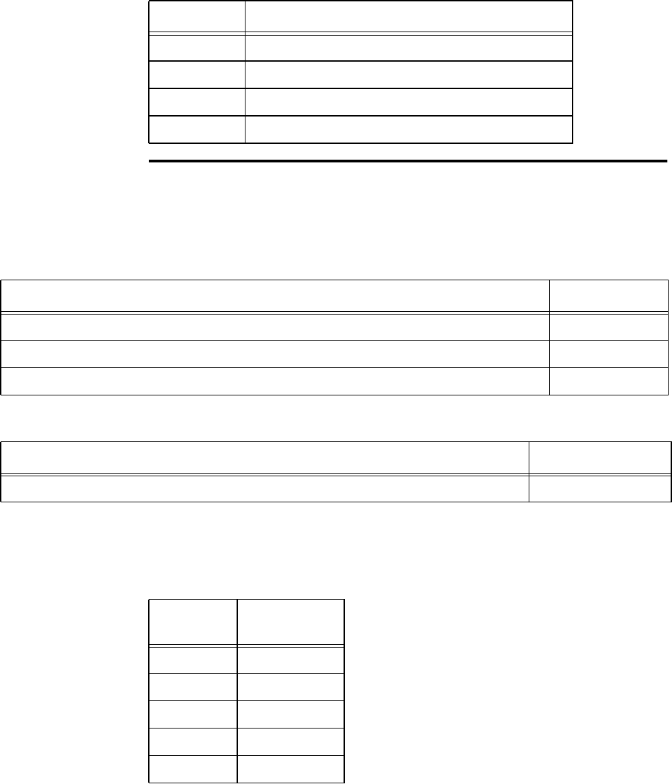
Configuring and Operating the Orion Reader Using TCP Commands
Use or disclosure of Proprietary Information contained on this sheet is subject to the restriction stated on the title page of this document. 6-57
Set Digital I/O Output Pulse Duration
This command sets the Digital I/O output pulse duration. Table 6-101 and Table 6-102
list the command and response data.
Output Pulse Duration — This field specifies the output pulse duration (digital out-
puts ON and OFF times). The digital outputs have a 50% duty cycle (Table 6-103).
03H Two-channel multiplexing (channels 0 and 1)
0CH Two-channel multiplexing (channels 2 and 3)
07H Three-channel multiplexing (channels 0, 1, and 2)
0FH Four-channel multiplexing (channels 0, 1, 2, and 3)
Table 6-100 RF Multiplexing Mode Values
Mode Value RF Multiplexing Mode
Table 6-101 Set Digital I/O Output Pulse Duration Command (000AH)
Set Digital I/O Output Pulse Duration Command Data Data Payload
Set Digital I/O Output Pulse Duration Command 000AH
Output Port Number: 0–3 for Port0–Port3 0XH
Output Pulse Duration 0XH
Table 6-102 Set Digital I/O Output Pulse Duration Response
Set Digital I/O Output Pulse Duration Response Data Data Payload
Set Digital I/O Output Pulse Duration Command 000AH
Table 6-103 Output Pulse Duration Values
Duration
Value Pulse
Duration (ms)
00H 4
01H 8
02H 12
03H 16
04H 20
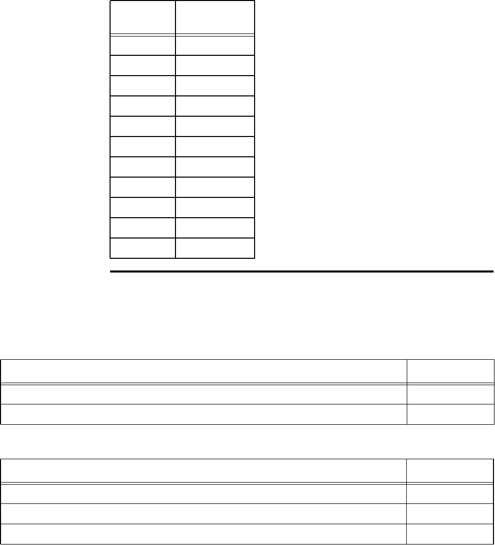
Orion Reader System Guide
6-58 Use or disclosure of Proprietary Information contained on this sheet is subject to the restriction stated on the title page of this document.
Get Digital I/O Output Pulse Duration
This command gets the Digital I/O output pulse duration. Table 6-104 and Table 6-
105 list the command and response data.
05H 24
06H 32
07H 40
08H 48
09H 60
0AH 76
0BH 152
0CH 228
0DH 300
0EH 376
0FH 752
Table 6-103 Output Pulse Duration Values
Duration
Value Pulse
Duration (ms)
Table 6-104 Get Digital I/O Output Pulse Duration Command (000BH)
Get Digital I/O Output Pulse Duration Command Data Data Payload
Get Digital I/O Output Pulse Duration Command 000BH
Output Port Number: 0–3 for Port0–Port3 0XH
Table 6-105 Get Digital I/O Output Pulse Duration Response
Get Digital I/O Output Pulse Duration Response Data Data Payload
Get Digital I/O Output Pulse Duration Command 000BH
Output Port Number: 0–3 for Port0–Port3 0XH
Output Pulse Duration 0XH

Configuring and Operating the Orion Reader Using TCP Commands
Use or disclosure of Proprietary Information contained on this sheet is subject to the restriction stated on the title page of this document. 6-59
Output Pulse Duration — This field specifies the output pulse duration (digital out-
puts ON and OFF times). The digital outputs have a 50% duty cycle (Table 6-106).
Table 6-106 Output Pulse Duration Values
Duration
Value Pulse
Duration (ms)
00H 4
01H 8
02H 12
03H 16
04H 20
05H 24
06H 32
07H 40
08H 48
09H 60
0AH 76
0BH 152
0CH 228
0DH 300
0EH 376
0FH 752
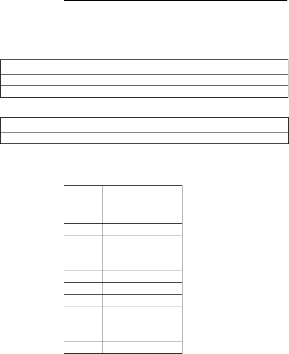
Orion Reader System Guide
6-60 Use or disclosure of Proprietary Information contained on this sheet is subject to the restriction stated on the title page of this document.
Set Digital I/O Minimum Presence True Period
This command sets the digital I/O minimum presence true period, which is the mini-
mum amount of time that the input must be valid. Table 6-107 and Table 6-108 list the
command and response data.
Minimum Presence True Period — This field specifies the minimum presence true
period (Table 6-109).
Table 6-107 Set Digital I/O Minimum Presence True Period Command (000CH)
Set Digital I/O Minimum PresenceTrue Period Command Data Data Payload
Set Digital I/O Minimum Presence True Period Command 000CH
Minimum Presence True Period 0XH
Table 6-108 Set Digital I/O Minimum Presence True Period Response
Set Digital I/O Minimum PresenceTrue Period Response Data Data Payload
Set Digital I/O Minimum Presence True Period Command 000CH
Table 6-109 Minimum Presence True Period Values
True
Period
Value True Period (ms)
00H 0 (always true)
01H 4
02H 8
03H 12
04H 20
05H 24
06H 32 (default)
07H 48
08H 60
09H 92
0AH 152
0BH 300
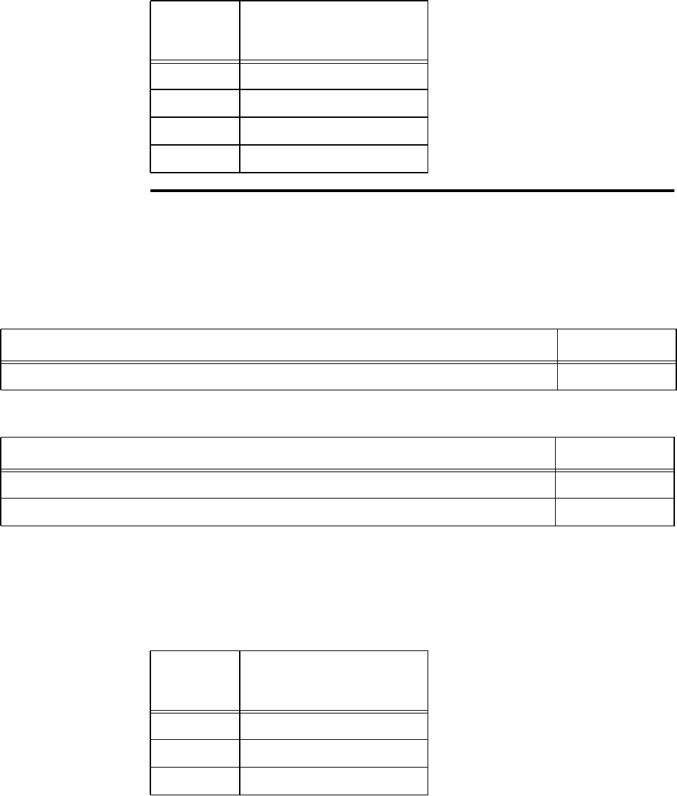
Configuring and Operating the Orion Reader Using TCP Commands
Use or disclosure of Proprietary Information contained on this sheet is subject to the restriction stated on the title page of this document. 6-61
Get Digital I/O Minimum Presence True Period
This command gets the digital I/O minimum presence true period, which is the mini-
mum amount of time that the input must be valid. Table 6-110 and Table 6-111 list the
command and response data.
Minimum Presence True Period — This field specifies the minimum presence true
period (Table 6-112).
0CH 452
0DH 600
0EH 752
0FH Infinite (never true)
Table 6-109 Minimum Presence True Period Values
True
Period
Value True Period (ms)
Table 6-110 Get Digital I/O Minimum Presence True Period Command (000DH)
Get Digital I/O Minimum PresenceTrue Period Command Data Data Payload
Get Digital I/O Minimum Presence True Period Command 000DH
Table 6-111 Get Digital I/O Minimum Presence True Period Response
Set Digital I/O Minimum PresenceTrue Period Response Data Data Payload
Set Digital I/O Minimum Presence True Period Command 000DH
Minimum Presence True Period 0XH
Table 6-112 Minimum Presence True Period Values
True
Period
Value True Period (ms)
00H 0 (always true)
01H 4
02H 8
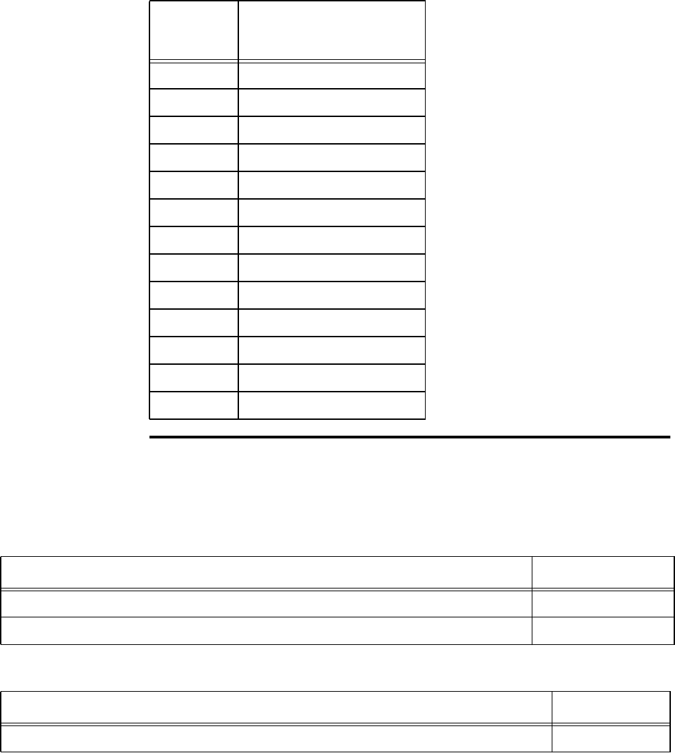
Orion Reader System Guide
6-62 Use or disclosure of Proprietary Information contained on this sheet is subject to the restriction stated on the title page of this document.
Set Digital I/O Sensor Input Inversion
This command sets the digital I/O sensor input inversion. Table 6-113 and Table 6-
114 list the command and response data.
The logic true inversion is in relationship with the OPTO22 digital input.
03H 12
04H 20
05H 24
06H 32 (default)
07H 48
08H 60
09H 92
0AH 152
0BH 300
0CH 452
0DH 600
0EH 752
0FH Infinite (never true)
Table 6-112 Minimum Presence True Period Values
True
Period
Value True Period (ms)
Table 6-113 Set Digital I/O Sensor Input Inversion Command (000EH)
Set Digital I/O Sensor Input Inversion Command Data Data Payload
Set Digital I/O Sensor Input Inversion Command 000EH
Logic True Inversion: 0 = normal logic true,1=invertedlogic true 0XH
Table 6-114 Set Digital I/O Sensor Input Inversion Command Response
Set Digital I/O Sensor Input Inversion Response Data Data Payload
Set Digital I/O Sensor Input Inversion Command 000EH
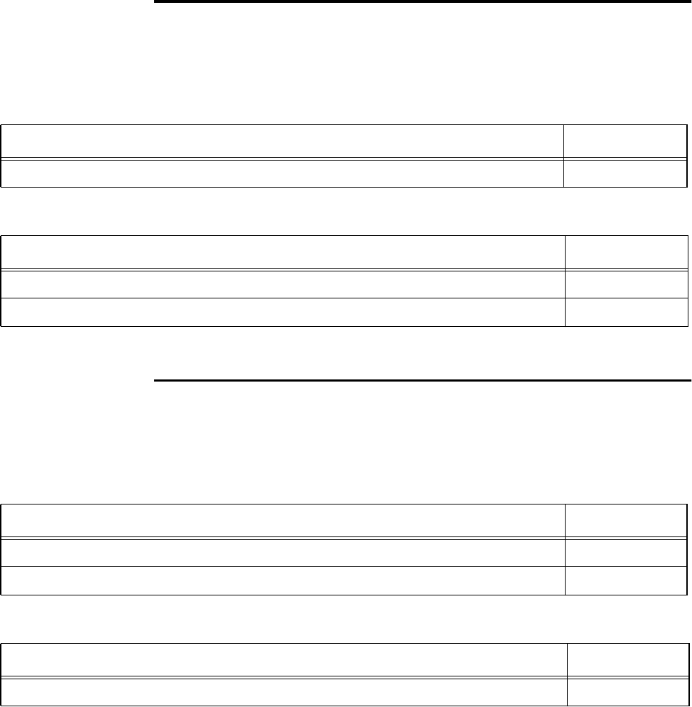
Configuring and Operating the Orion Reader Using TCP Commands
Use or disclosure of Proprietary Information contained on this sheet is subject to the restriction stated on the title page of this document. 6-63
Get Digital I/O Sensor Input Inversion
This command gets the digital I/O sensor input inversion. Table 6-115 and Table 6-
116 list the command and response data.
The logic true inversion is in relationship with the OPTO22 digital input.
Set Digital I/O Port Configuration
This command configures the digital I/O ports. Table 6-117 and Table 6-118 list the
command and response data.
Table 6-115 Get Digital I/O Sensor Input Inversion Command (000FH)
Get Digital I/O Sensor Input Inversion Command Data Data Payload
Get Digital I/O Sensor Input Inversion Command 000FH
Table 6-116 Get Digital I/O Sensor Input Inversion Response
Get Digital I/O Sensor Input Inversion Response Data Data Payload
Get Digital I/O Sensor Input Inversion Command 000FH
Logic True Inversion: 0 = normal logic true,1=invertedlogic true 0XH
Table 6-117 Set Digital I/O Port Configuration Command (0010H)
Set Digital I/O Port Configuration Command Data Data Payload
Set Digital I/O Port Configuration Command 0010H
Port Configuration 0XH
Table 6-118 Set Digital I/O Port Configuration Response
Set Digital I/O Port Configuration Response Data Data Payload
Set Digital I/O Port Configuration Command 0010H
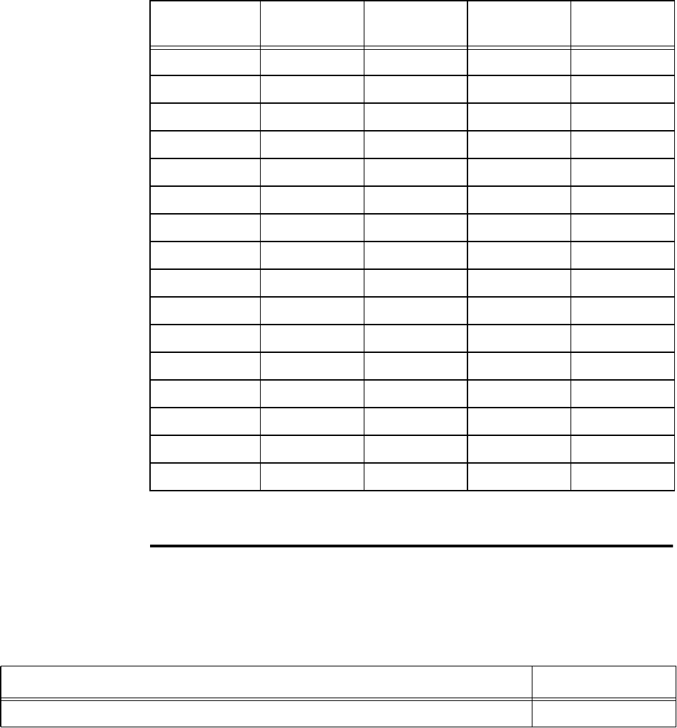
Orion Reader System Guide
6-64 Use or disclosure of Proprietary Information contained on this sheet is subject to the restriction stated on the title page of this document.
Port Configuration — This field specifies the digital port input/output configuration.
In Table 6-119, INPUT = 0 and OUTPUT = 1.
Note: RESET READER command required for changes to take effect.
Get Digital I/O Port Configuration
This command gets the digital I/O port configuration settings. Table 6-120 and Table
6-121 list the command and response data.
Table 6-119 Digital I/O Port Configuration Values
Configuration
Value Digital Port 3 Digital Port 2 Digital Port 1 Digital Port 0
00H INPUT INPUT INPUT INPUT
01H INPUT INPUT INPUT OUTPUT
02H INPUT INPUT OUTPUT INPUT
03H INPUT INPUT OUTPUT OUTPUT
04H INPUT OUTPUT INPUT INPUT
05H INPUT OUTPUT INPUT OUTPUT
06H INPUT OUTPUT OUTPUT INPUT
07H INPUT OUTPUT OUTPUT OUTPUT
08H OUTPUT INPUT INPUT INPUT
09H OUTPUT INPUT INPUT OUTPUT
0AH OUTPUT INPUT OUTPUT INPUT
0BH OUTPUT INPUT OUTPUT OUTPUT
0CH OUTPUT OUTPUT INPUT INPUT
0DH OUTPUT OUTPUT INPUT OUTPUT
0EH OUTPUT OUTPUT OUTPUT INPUT
0FH OUTPUT OUTPUT OUTPUT OUTPUT
Table 6-120 Get Digital I/O Port Configuration Command (0011H)
Get Digital I/O Port Configuration Command Data Data Payload
Get Digital I/O Port Configuration Command 0011H
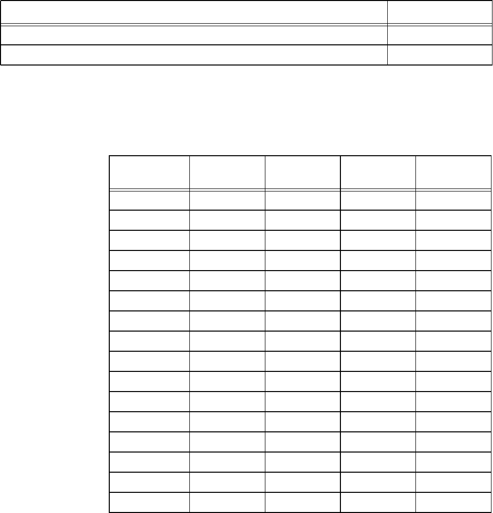
Configuring and Operating the Orion Reader Using TCP Commands
Use or disclosure of Proprietary Information contained on this sheet is subject to the restriction stated on the title page of this document. 6-65
Port Configuration — This field specifies the digital port input/output configuration.
In Table 6-122, INPUT = 0 and OUTPUT = 1.
Table 6-121 Set Digital I/O Port Configuration Response
Get Digital I/O Port Configuration Response Data Data Payload
Get Digital I/O Port Configuration Command 0011H
Port Configuration 0XH
Table 6-122 Digital I/O Port Configuration Values
Configuration
Value Digital Port 3 Digital Port 2 Digital Port 1 Digital Port 0
00H INPUT INPUT INPUT INPUT
01H INPUT INPUT INPUT OUTPUT
02H INPUT INPUT OUTPUT INPUT
03H INPUT INPUT OUTPUT OUTPUT
04H INPUT OUTPUT INPUT INPUT
05H INPUT OUTPUT INPUT OUTPUT
06H INPUT OUTPUT OUTPUT INPUT
07H INPUT OUTPUT OUTPUT OUTPUT
08H OUTPUT INPUT INPUT INPUT
09H OUTPUT INPUT INPUT OUTPUT
0AH OUTPUT INPUT OUTPUT INPUT
0BH OUTPUT INPUT OUTPUT OUTPUT
0CH OUTPUT OUTPUT INPUT INPUT
0DH OUTPUT OUTPUT INPUT OUTPUT
0EH OUTPUT OUTPUT OUTPUT INPUT
0FH OUTPUT OUTPUT OUTPUT OUTPUT

Orion Reader System Guide
6-66 Use or disclosure of Proprietary Information contained on this sheet is subject to the restriction stated on the title page of this document.
Set Digital I/O Sensor Input Report
This command sets the digital I/O sensor input report mask. Table 6-123 and Table 6-
124 list the command and response data.
Get Digital I/O Sensor Input Report
This command gets the digital I/O sensor input report mask. Table 6-125 and Table 6-
126 list the command and response data.
Set Digital I/O Presence RF Control Algorithm
Table 6-123 Set Digital I/O Sensor Input Report Command (0012H)
Set Digital I/O Sensor Input Report Command Data Data Payload
Set Digital I/O Sensor Input Report Command 0012H
Sensor Input Report Mask: 0 = reports disabled, 1 = reports enabled 0XH
Table 6-124 Set Digital I/O Sensor Input Report Response
Set Digital I/O Sensor Input Report Response Data Data Payload
Set Digital I/O Sensor Input Report Command 0012H
Table 6-125 Get Digital I/O Sensor Input Report Command (0013H)
Get Digital I/O Sensor Input Report Command Data Data Payload
Get Digital I/O Sensor Input Report Command 0013H
Table 6-126 Set Digital I/O Sensor Input Report Response
Get Digital I/O Sensor Input Report Response Data Data Payload
Get Digital I/O Sensor Input Report Command 0013H
Sensor Input Report Mask: 0 = reports disabled, 1 = reports enabled 0XH
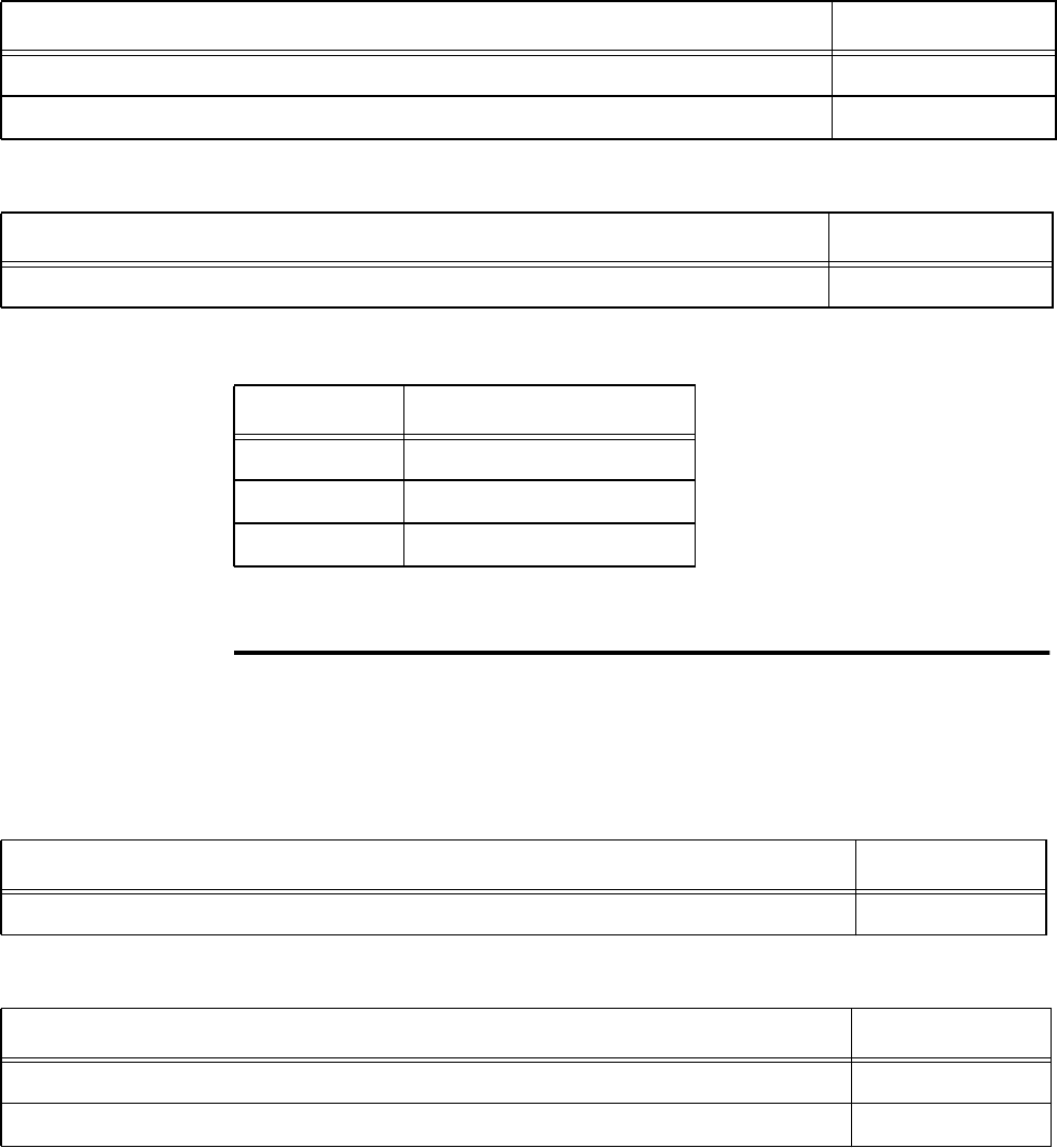
Configuring and Operating the Orion Reader Using TCP Commands
Use or disclosure of Proprietary Information contained on this sheet is subject to the restriction stated on the title page of this document. 6-67
This command sets the digital I/O presence RF control algorithm. Table 6-127 and
Table 6-128 list the command and response data.
RF Control Algorithm — This field specifies the trigger for RF de-assertion.
Get Digital I/O Presence RF Control Algorithm
This command gets the digital I/O presence RF control algorithm. Table 6-129 and
Table 6-130 list the command and response data.
Table 6-127 Set Digital I/O Presence RF Control Algorithm Command (0014H)
Set Digital I/O Presence RF Control Algorithm Command Data Data Payload
Set Digital I/O Presence RF Control Algorithm Command 0014H
RF Control Algorithm 0XH
Table 6-128 Set Digital I/O Presence RF Control Algorithm Response
Set Digital I/O RF Control Response Data Data Payload
Set Digital I/O Presence RF Control Algorithm Command 0014H
Control Value RF Power Off
00H On time-out only
01H Time-out or good tag read
02H Time-out or presence false
Table 6-129 Get Digital I/O Presence RF Control Algorithm Command (0015H)
Get Digital I/O Presence RF Control Algorithm Command Data Data Payload
Get Digital I/O Presence RF Control Algorithm Command 0015H
Table 6-130 Get Digital I/O Presence RF Control Algorithm Response
Get Digital I/O RF Control Response Data Data Payload
Get Digital I/O Presence RF Control Algorithm Command 0015H
RF Control Algorithm 0XH
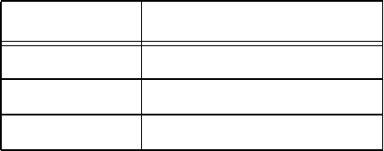
Orion Reader System Guide
6-68 Use or disclosure of Proprietary Information contained on this sheet is subject to the restriction stated on the title page of this document.
RF Control Algorithm — This field specifies the trigger for RF de-assertion.
Control Value RF Power Off
00H On time-out only
01H Time-out or good tag read
02H Time-out or presence false
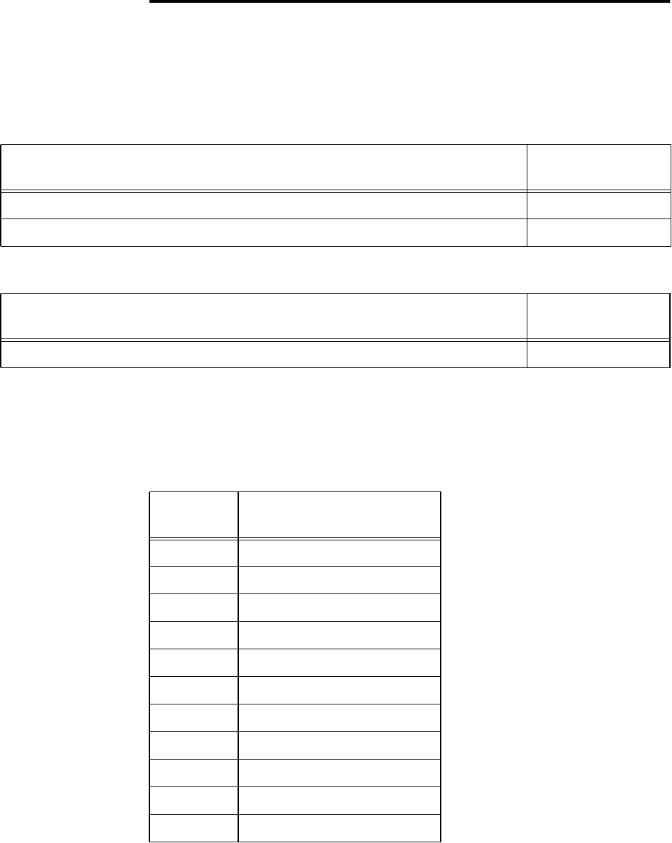
Configuring and Operating the Orion Reader Using TCP Commands
Use or disclosure of Proprietary Information contained on this sheet is subject to the restriction stated on the title page of this document. 6-69
Set Digital I/O Presence RF Control Time-out
Period
This command sets the digital I/O presence RF control time-out period. Table 6-131
and Table 6-132 list the command and response data.
RF Assertion Duration — This field specifies the RF assertion duration (time-out
period) (Table 6-133).
Table 6-131 Set Digital I/O Presence RF Control Time-out Period Command (0016H)
Set Digital I/O Presence RF ControlTime-out Period
Command Data Data Payload
Set Digital I/O Presence RF Control Time-out Period Command 0016H
RF Assertion Duration 0XH
Table 6-132 Set Digital I/O Presence RF Control Time-out Period Response
Set Digital I/O Presence RF ControlTime-out Period
Response Data Data Payload
Set Digital I/O Presence RF Control Time-out Period Command 0016H
Table 6-133 RF Assertion Duration Values
Duration
Value Assertion Duration (ms)
00H 0 (always true)
01H 20
02H 32
03H 60
04H 92
05H 152
06H 300 (factory setting)
07H 452
08H 600
09H 752
0AH 1500
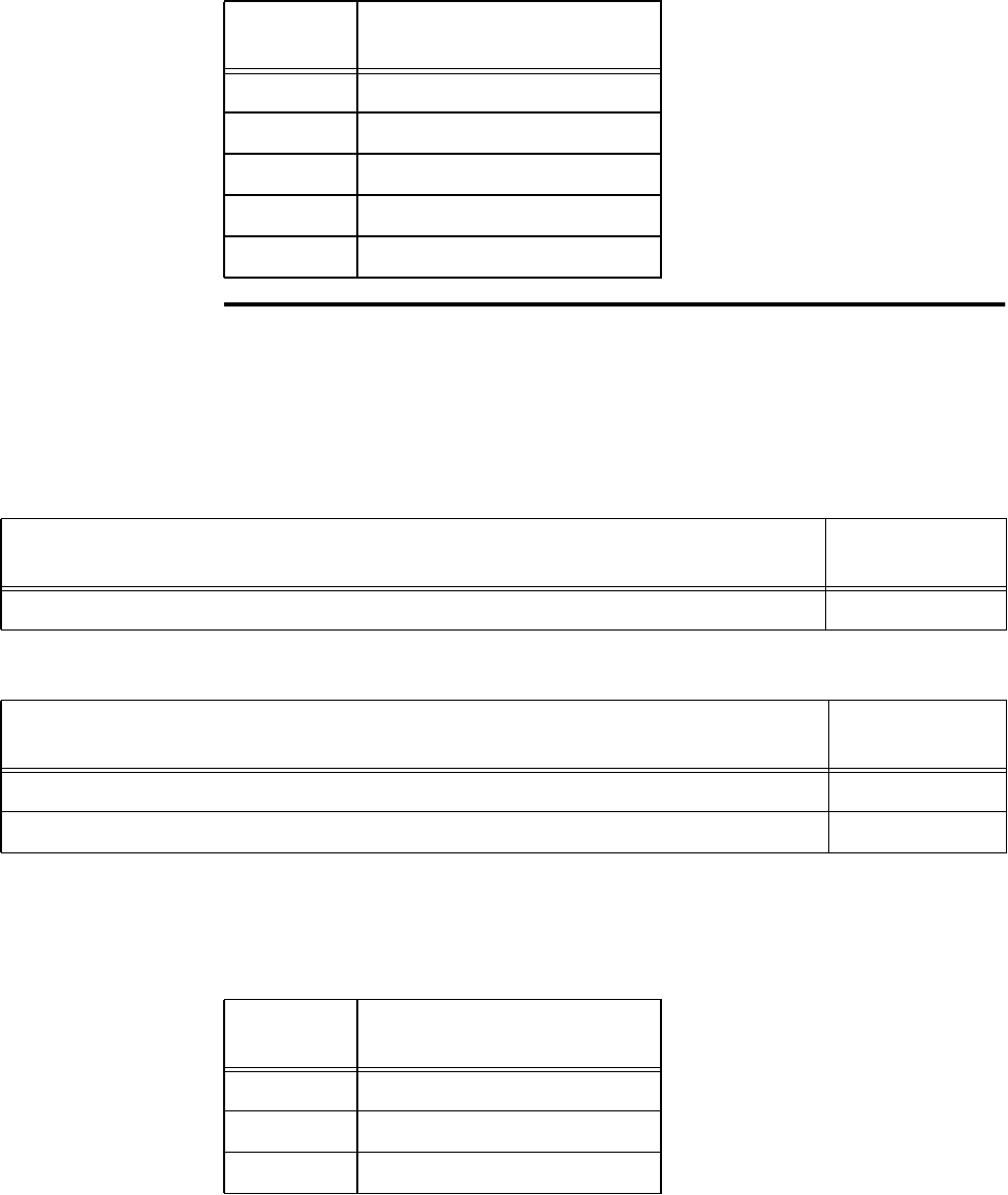
Orion Reader System Guide
6-70 Use or disclosure of Proprietary Information contained on this sheet is subject to the restriction stated on the title page of this document.
Get Digital I/O Presence RF Control Time-out
Period
This command gets the digital I/O presence RF control time-out period. Table 6-134
and Table 6-135 list the command and response data.
RF Assertion Duration — This field specifies the RF assertion duration (time-out
period) (Table 6-136).
0BH 3000
0CH 6000
0DH 12000
0EH 24000
0FH Infinite (never true)
Table 6-133 RF Assertion Duration Values
Duration
Value Assertion Duration (ms)
Table 6-134 Get Digital I/O Presence RF Control Time-out Period Command (0017H)
Get Digital I/O Presence RF ControlTime-out Period
Command Data Data Payload
Get Digital I/O Presence RF Control Time-out Period Command 0017H
Table 6-135 Get Digital I/O Presence RF Control Time-out Period Response)
Get Digital I/O Presence RF ControlTime-out Period
Response Data Data Payload
Get Digital I/O Presence RF Control Time-out Period Command 0017H
RF Assertion Duration 0XH
Table 6-136 RF Assertion Duration Values
Duration
Value Assertion Duration (ms)
00H 0 (always true)
01H 20
02H 32
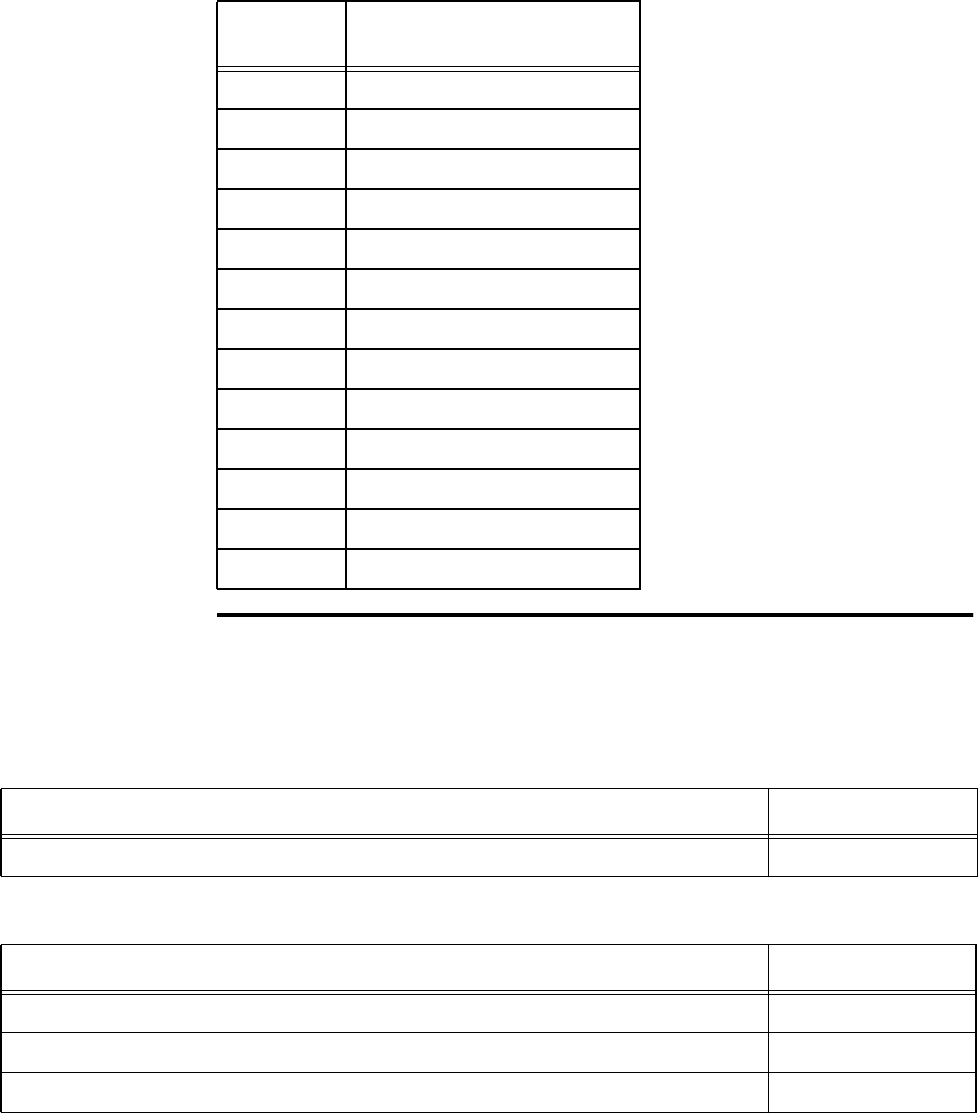
Configuring and Operating the Orion Reader Using TCP Commands
Use or disclosure of Proprietary Information contained on this sheet is subject to the restriction stated on the title page of this document. 6-71
Get Digital I/O Port Status
This command gets the digital I/O port configuration and status. Table 6-137 and
Table 6-138 list the command and response data.
03H 60
04H 92
05H 152
06H 300 (factory setting)
07H 452
08H 600
09H 752
0AH 1500
0BH 3000
0CH 6000
0DH 12000
0EH 24000
0FH Infinite (never true)
Table 6-136 RF Assertion Duration Values
Duration
Value Assertion Duration (ms)
Table 6-137 Get Digital I/O Port Status Command (0018H)
Get Digital I/O Port Status Command Data Data Payload
Get Digital I/O Port Status Command 0018H
Table 6-138 Get Digital I/O Port Status Response
Get Digital I/O Port Status Response Data Data Payload
Get Digital I/O Port Status Command 0018H
Port Configuration 0XH
Port Status 0XH

Orion Reader System Guide
6-72 Use or disclosure of Proprietary Information contained on this sheet is subject to the restriction stated on the title page of this document.
Port Configuration — This field specifies the digital port input/output configuration.
In Table 6-139, INPUT = 0 and OUTPUT = 1.
Port Status — This field specifies the digital port status. In Table 6-140, LOW = 0
and HIGH = 1.
Table 6-139 Port Configuration Values
Configuration
Value Digital Port 3 Digital Port 2 Digital Port 1 Digital Port 0
00H INPUT INPUT INPUT INPUT
01H INPUT INPUT INPUT OUTPUT
02H INPUT INPUT OUTPUT INPUT
03H INPUT INPUT OUTPUT OUTPUT
04H INPUT OUTPUT INPUT INPUT
05H INPUT OUTPUT INPUT OUTPUT
06H INPUT OUTPUT OUTPUT INPUT
07H INPUT OUTPUT OUTPUT OUTPUT
08H OUTPUT INPUT INPUT INPUT
09H OUTPUT INPUT INPUT OUTPUT
0AH OUTPUT INPUT OUTPUT INPUT
0BH OUTPUT INPUT OUTPUT OUTPUT
0CH OUTPUT OUTPUT INPUT INPUT
0DH OUTPUT OUTPUT INPUT OUTPUT
0EH OUTPUT OUTPUT OUTPUT INPUT
0FH OUTPUT OUTPUT OUTPUT OUTPUT
Table 6-140 Port Status Values
Status Value Digital Port 3 Digital Port 2 Digital Port 1 Digital Port 0
00H LOW LOW LOW LOW
01H LOW LOW LOW HIGH
02H LOW LOW HIGH LOW
03H LOW LOW HIGH HIGH
04H LOW HIGH LOW LOW
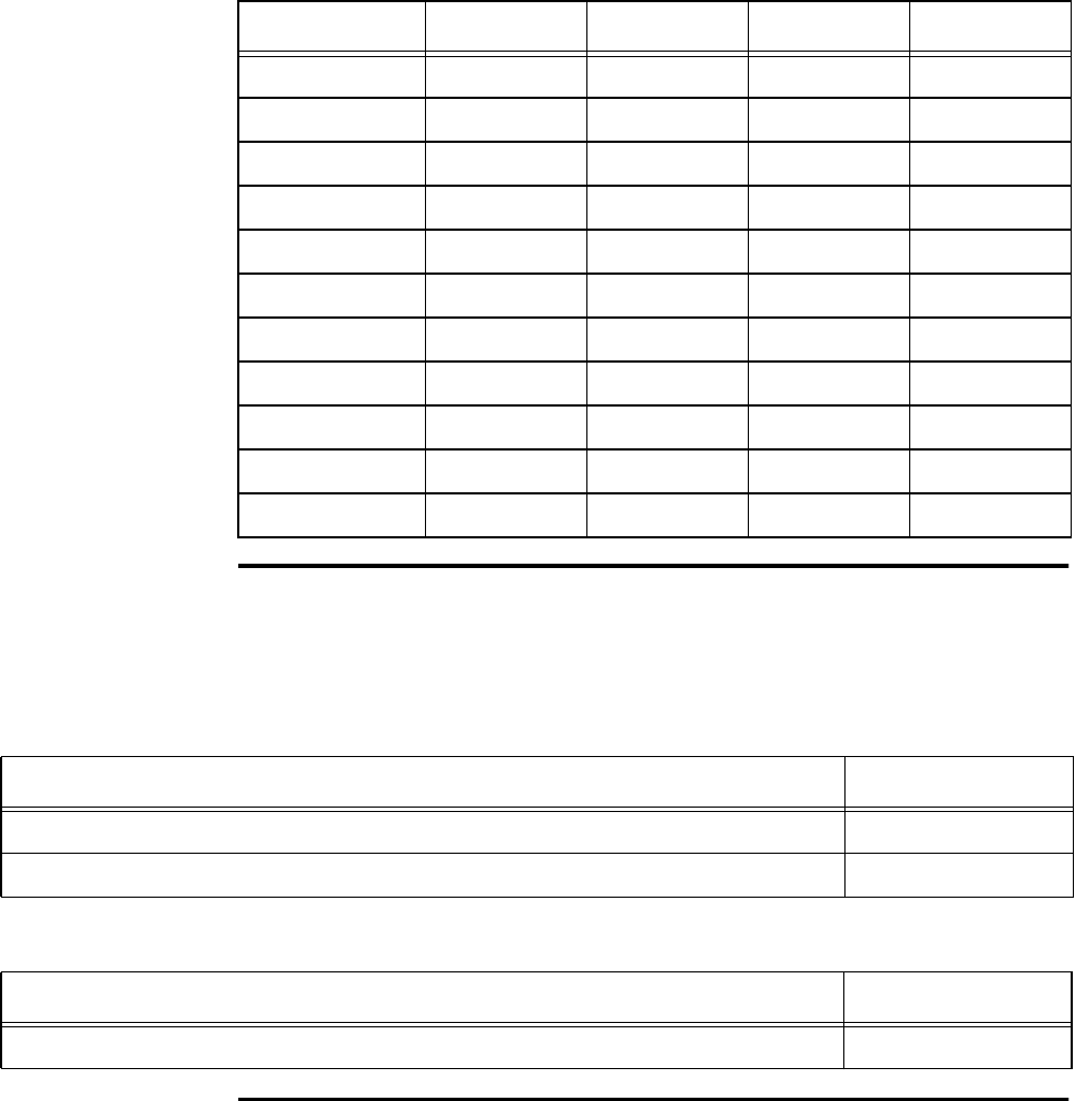
Configuring and Operating the Orion Reader Using TCP Commands
Use or disclosure of Proprietary Information contained on this sheet is subject to the restriction stated on the title page of this document. 6-73
Set Digital I/O Mode
This command sets the digital I/O start and stop modes. Table 6-141 and Table 6-142
list the command and response data.
Get Digital I/O Mode
05H LOW HIGH LOW HIGH
06H LOW HIGH HIGH LOW
07H LOW HIGH HIGH HIGH
08H HIGH LOW LOW LOW
09H HIGH LOW LOW HIGH
0AH HIGH LOW HIGH LOW
0BH HIGH LOW HIGH HIGH
0CH HIGH HIGH LOW LOW
0DH HIGH HIGH LOW HIGH
0EH HIGH HIGH HIGH LOW
0FH HIGH HIGH HIGH HIGH
Table 6-140 Port Status Values
Status Value Digital Port 3 Digital Port 2 Digital Port 1 Digital Port 0
Table 6-141 Set Digital I/O Mode Command (0019H)
Set Digital I/O Mode Command Data Data Payload
Set Digital I/O Mode Command 0019H
Digital I/O Mode: 0 = stop, 1 = start 0XH
Table 6-142 Set Digital I/O Mode Response
Set Digital I/O Mode Response Data Data Payload
Set Digital I/O Mode Command 0019H

Orion Reader System Guide
6-74 Use or disclosure of Proprietary Information contained on this sheet is subject to the restriction stated on the title page of this document.
This command gets the digital I/O mode. Table 6-143 and Table 6-144 list the com-
mand and response data.
Set External Interrupt Control
This command sets the external interrupt control for the digital I/O devices. Table 6-
145 and Table 6-146 list the command and response data.
Polarity — used to establish the polarity of the external interrupt
Table 6-143 Get Digital I/O Mode Command (001AH)
Get Digital I/O Mode Command Data Data Payload
Get Digital I/O Mode Command 001AH
Table 6-144 Get Digital I/O Mode Response
Get Digital I/O Mode Response Data Data Payload
Get Digital I/O Mode Command 001AH
Digital I/O Mode: 0 = stop, 1 = start 0XH
Table 6-145 Set External Interrupt Control Command (056DH)
Set External Interrupt Control Command Data Data Payload
Bits 7–0
Set External Interrupt Control Command 05H
Command (continued) 6DH
Lead time XXH
Lead time (continued) XXH
Lag time XXH
Lag time (continued) XXH
Polarity XXH
Event Mode XXH
Bit Value Event Type
0 Positive polarity (default)
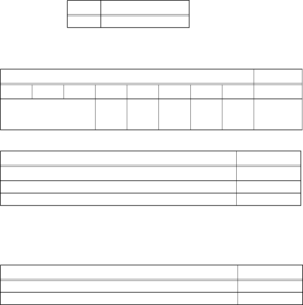
Configuring and Operating the Orion Reader Using TCP Commands
Use or disclosure of Proprietary Information contained on this sheet is subject to the restriction stated on the title page of this document. 6-75
Event Mode — specifies type of event
Lead and Lag Times — equal to 10 milliseconds multiplied by the decimal equiva-
lent of the data payload
Changing the polarity for a light curtain using the Set External Interrupt Control com-
mand after the polarity has been initially established requires that two digital I/O com-
mand group commands be sent prior to using the Set External Interrupt Control
command. Issue the commands in the order shown in Table 6-147.
When issuing these commands, ensure that the Digital I/O mode is stopped and the
sensor input inversion command is set to inverted.
Note: RESET READER command required for changes to take effect.
1 Negative polarity
Bit Value Event Type
Event Mode Command Data Data Payload
Bit 7 Bit 6 Bit 5 Bit 4 Bit 3 Bit 2 Bit 1 Bit 0
Reserved Second
carentry
enable
No tag
read
enable
Light
curtain
entry
enable
Light
curtain
exit
enable
Lag
timer
time-out
enable
XXH
Table 6-146 Set External Interrupt Control Response
Set External Interrupt Control Response Data Data Payload
Bits 7–0
Set External Interrupt Control Command 05H
Command (continued) 6DH
Table 6-147 Digital I/O Commands
Digital I/O Commands Command Code
Set Digital I/O Mode 0019H
Set Digital I/O Sensor Input Inversion 000EH

Orion Reader System Guide
6-76 Use or disclosure of Proprietary Information contained on this sheet is subject to the restriction stated on the title page of this document.
Get External Interrupt Control
This command gets the external interrupt control for the digital I/O devices. Table 6-
148 and Table 6-149 list the command and response data.
Table 6-150 lists the light curtain asynchronous responses.
Table 6-148 Get External Interrupt Control Command (06ADH)
Get External Interrupt Control Command Data Data Payload
Bits 7–0
Get External Interrupt Control Command 06H
Command (continued) ADH
Table 6-149 Get External Interrupt Control Response
Get External Interrupt Control Response Data Data Payload
Bits 7–0
Get External Interrupt Control Command 06H
Command (continued) ADH
Lead time XXH
Lead time (continued) XXH
Lag time XXH
Lag time (continued) XXH
Polarity XXH
Event Mode XXH
Table 6-150 Light Curtain Asynchronous Response (8003H)
Light Curtain Asynchronous Response Data Data Payload
Bits 7–0
Record Type (MSB) 80H
Record Type (LSB) 03H
Event XXH
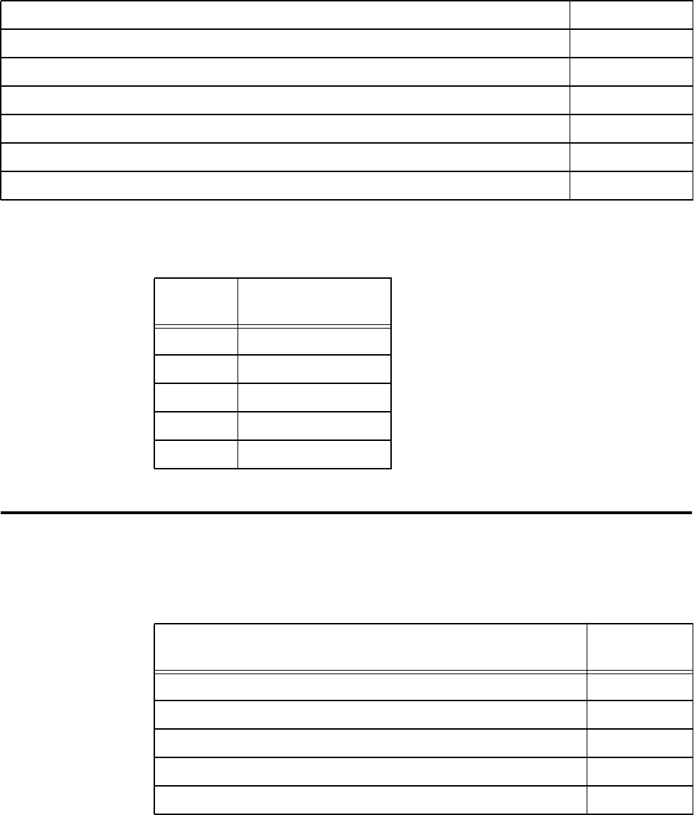
Configuring and Operating the Orion Reader Using TCP Commands
Use or disclosure of Proprietary Information contained on this sheet is subject to the restriction stated on the title page of this document. 6-77
Event — This field specifies the event type.
RF Transceiver Command Group Commands (2000H)
Table 6-151 lists the RF Transceiver Command Group commands that are used in the
Orion multiprotocol reader.
Hour XXH
Minute XXH
Second XXH
Hundredths of Seconds XXH
Month XXH
Day XXH
Year XXH
Table 6-150 Light Curtain Asynchronous Response (8003H)
Field
Value Event Type
01H Lag timer time-out
02H Light curtain exit
04H Light curtain entry
08H No tag read
10H Second car entry
Table 6-151 RF Transceiver Command Group Command
RF Transceiver Configuration Command Command
Code
Set Attenuation 51H
Get Attenuation 52H
Set Data Detect 53H
Get Data Detect 54H
Set Line Loss 55H

Orion Reader System Guide
6-78 Use or disclosure of Proprietary Information contained on this sheet is subject to the restriction stated on the title page of this document.
RF Transceiver Command Group Responses
Table 6-152 lists the responses and codes for the RF transceiver command group.
Get Line Loss 56H
Set Uplink Source Control 57H
Get Uplink Source Control 58H
Reserved 59H
Set Frequency in MHz 60H
Get Frequency in MHz 61H
Table 6-152 RF Tranceiver Command Group Responses
RF Transceiver Response Response
Code
Synchronous OK Status Responses 88XXH
Reserved 8800H
Reserved 8801H
Asynchronous OK Status Responses 48XXH
Command Complete 4800H
Command In Progress 4801H
Unsolicited OK Status Responses 28XXH
Reserved 84XXH
Reserved 44XXH
Reserved 24XXH
Table 6-151 RF Transceiver Command Group Command
RF Transceiver Configuration Command Command
Code

Configuring and Operating the Orion Reader Using TCP Commands
Use or disclosure of Proprietary Information contained on this sheet is subject to the restriction stated on the title page of this document. 6-79
Synchronous Error Status Responses 82XXH
Message Length Error 8200H
Message Sequence Error 8201H
Reserved 8202H
Command Group Error 8203H
Reserved 8204H
Reserved 8205H
Reserved 8206H
Reserved 8207H
Reserved 8208H
Data Acknowledge Response Error 8209H
Reserved 820AH
Asynchronous Error Status Responses 42XXH
Message Length Error 4200H
Command Sequence Error 4201H
Reserved 4202H
Command Group Error 4203H
Command Time-out Error 4204H
Reserved 4205H
Command Failed Error 4206H
System Command Error 4207H
Sub-command Error 4208H
Reserved 4209H
Invalid Control Word Error 420AH
Table 6-152 RF Tranceiver Command Group Responses
RF Transceiver Response Response
Code

Orion Reader System Guide
6-80 Use or disclosure of Proprietary Information contained on this sheet is subject to the restriction stated on the title page of this document.
RF Transceiver Command Group Response Data
Synchronous OK Status Responses
The following Digital I/O command group asynchronous OK status responses use the
specified data payload.
Command Complete (4800H)
Command In Progress (4801H)
Synchronous Error Status Responses
The following RF Transceiver command group synchronous error status responses
use the specified data payload.
Unsolicited Error Status Responses 22XXH
Synchronous Control Status Responses 81XXH
Data Acknowledge (Ack), data valid 8100H
Data Negative Acknowledge (Nack), data invalid 8101H
Reserved 8102H
Reserved 8104H
Asynchronous Control Status Responses 41XXH
Unsolicited Control Status Responses 21XXH
Command In Progress Response Data Data
Payload
Digital I/O Command Group Command (sub-command) XXXXH
Command In Progress Response Data Data
Payload
Digital I/O Command Group Command (sub-command) XXXXH
Table 6-152 RF Tranceiver Command Group Responses
RF Transceiver Response Response
Code

Configuring and Operating the Orion Reader Using TCP Commands
Use or disclosure of Proprietary Information contained on this sheet is subject to the restriction stated on the title page of this document. 6-81
Message Length Error Response Data (8200H)
Message Sequence Error Response Data (8201H)
Command Group Error Response Data (8203H)
Data Acknowledge Response Error Response Data (8209H)
Asynchronous Error Status Responses
The following RF Transceiver command group asynchronous error status responses
use the specified data payload.
Message Length Error Response Data Data
Payload
Expected Message Length XXXXH
Received Message Length XXXXH
Message Sequence Error Response Data Data
Payload
Expected Message Sequence Number XXH
Received Message Sequence Number XXH
Command Group Error Response Data Data
Payload
Invalid Command Group XXXXH
Data Acknowledge Response Error Response Data Data
Payload
Invalid Data Acknowledge Response XXXXH

Orion Reader System Guide
6-82 Use or disclosure of Proprietary Information contained on this sheet is subject to the restriction stated on the title page of this document.
Message Length Error Response Data (4200H)
Command Sequence Error Response Data (4201H)
Command Group Error (4203H)
Command Time-out Error (4204H)
Command Failed Error (4206H)
System Command Error (4207H)
Message Length Error Response Data Data
Payload
Expected Message Length XXXXH
Received Message Length XXXXH
Command Sequence Error Response Data Data
Payload
Expected Command Sequence Number XXH
Received Command Sequence Number XXH
Command Group Error Response Data Data
Payload
Invalid Command Group XXXXH
Command Time-out Error Response Data Data
Payload
N/A
Command Failed Error Response Data Data
Payload
RF Transceiver Command Group Command (sub-command) XXXXH
System Command Error Response Data Data
Payload
N/A
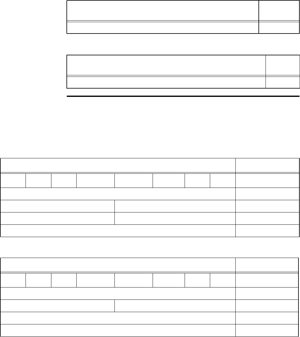
Configuring and Operating the Orion Reader Using TCP Commands
Use or disclosure of Proprietary Information contained on this sheet is subject to the restriction stated on the title page of this document. 6-83
Sub-Command Error (4208H))
Invalid Control Word Error (420AH)
Set RF Attenuation
This command sets the RF attenuation for the specific protocol from 0 to 15 decibels
(dB) in 1-dB increments. Table 6-153 and Table 6-154 list the command and response
data.
Sub-Command Error Response Data Data
Payload
Sub-Command XXH
Invalid Control Word Error Response Data Data
Payload
N/A
Table 6-153 Set RF Attenuation Command (51H)
Set RF Attenuation Command Data Data Payload
Bit 7 Bit 6 Bit 5 Bit 4 Bit 3 Bit 2 Bit 1 Bit 0
Set RF Attenuation Command 51H
Protocol Reserved X0H
Downlink Attenuation Uplink Attenuation XXH
Carriage Return 0DH
Table 6-154 Set RF Attenuation Response
Set RF Attenuation Response Data Data Payload
Bit 7 Bit 6 Bit 5 Bit 4 Bit 3 Bit 2 Bit 1 Bit 0
Set RF Attenuation Command 51H
Protocol Reserved X0H
ACK or NACK, where ACK = 0 and NACK = 1 0XH
Carriage Return 0DH
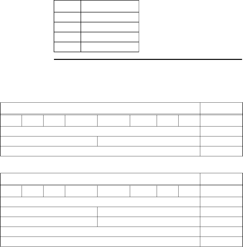
Orion Reader System Guide
6-84 Use or disclosure of Proprietary Information contained on this sheet is subject to the restriction stated on the title page of this document.
Protocol — This field sets the protocol for the RF Attenuation command
Get RF Attenuation
This command gets the RF attenuation as set using the Set RF Attenuation command.
Table 6-155 and Table 6-156 list the command and response data.
Protocol Definition
2IAG
3 CVISN
4 Title 21
8 ISO 18000-6C (EPC)
Table 6-155 Get RF Attenuation Command (52H)
Get RF Attenuation Command Data Data Payload
Bit 7 Bit 6 Bit 5 Bit 4 Bit 3 Bit 2 Bit 1 Bit 0
Get RF Attenuation Command 52H
Protocol Reserved X0H
Carriage Return 0DH
Table 6-156 Get RF Attenuation Response
Get RF Attenuation Response Data Data Payload
Bit 7 Bit 6 Bit 5 Bit 4 Bit 3 Bit 2 Bit 1 Bit 0
Get RF Attenuation Command 52H
Protocol Reserved X0H
Downlink Attenuation Uplink Attenuation XXH
ACK or NACK, where ACK = 0 and NACK = 1 0XH
Carriage Return 0DH
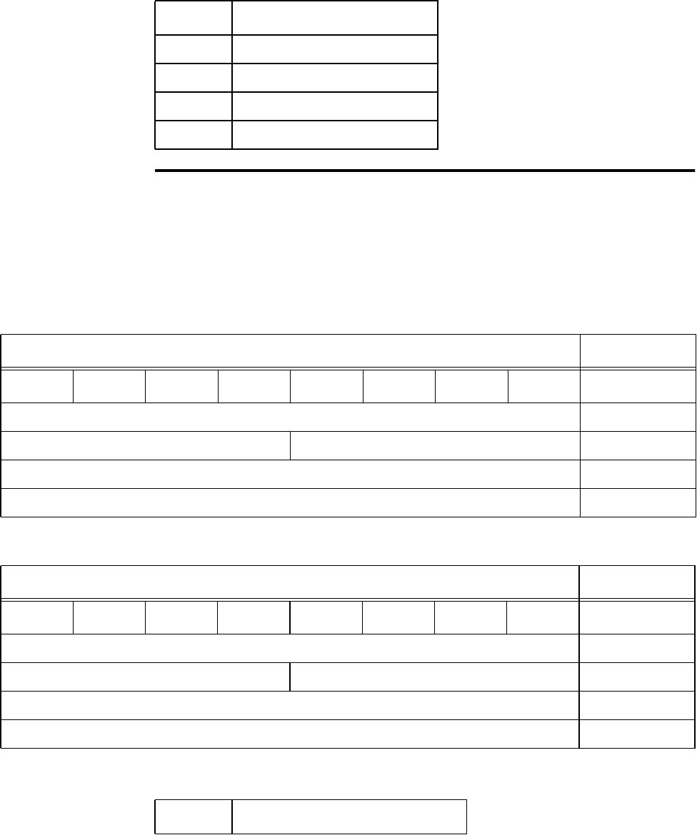
Configuring and Operating the Orion Reader Using TCP Commands
Use or disclosure of Proprietary Information contained on this sheet is subject to the restriction stated on the title page of this document. 6-85
Protocol — This field specifies the protocol for the Get RF Attenuation command.
Set Data Detect
This command sets the independent detection threshold levels for backscatter proto-
cols of up to 20 dB in 1-dB increments via the command interface port. The respective
protocol response is not passed until the data detect threshold has been exceeded.
Table 6-157 and Table 6-158 list the command and response data.
Protocol — This field sets the protocol for the Data Detect command.
Protocol Definition
2IAG
3 CVISN
4 Title 21
8 ISO 18000-6C (EPC)
Table 6-157 Set Data Detect Command (53H)
Set Data Detect Command Data Data Payload
Bit 7 Bit 6 Bit 5 Bit 4 Bit 3 Bit 2 Bit 1 Bit 0
Set Data Detect Command 53H
Protocol Reserved X0H
Data Detect Value (0–20) XXH
Carriage Return 0DH
Table 6-158 Set Data Detect Response
Set Data Detect Response Data Data Payload
Bit 7 Bit 6 Bit 5 Bit 4 Bit 3 Bit 2 Bit 1 Bit 0
Set Data Detect Command 53H
Protocol Reserved X0H
ACK or NACK, where ACK = 0 and NACK = 1 0XH
Carriage Return 0DH
Protocol Definition
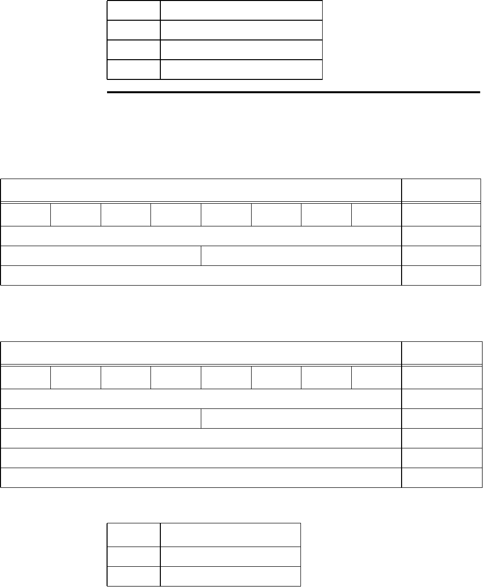
Orion Reader System Guide
6-86 Use or disclosure of Proprietary Information contained on this sheet is subject to the restriction stated on the title page of this document.
Get Data Detect
This command gets the data detect value. Table 6-159 and Table 6-160 list the com-
mand and response data.
Protocol — This field specifies the protocol for the Data Detect command.
2IAG
3 CVISN
4 Title 21
8 ISO 18000-6C (EPC)
Table 6-159 Get Data Detect Command
Get Data Detect Command Data Data Payload
Bit 7 Bit 6 Bit 5 Bit 4 Bit 3 Bit 2 Bit 1 Bit 0
Get Data Detect Command 54H
Protocol Reserved X0H
Carriage Return 0DH
Table 6-160 Get Data Detect Response
Get Data Detect Response Data Data Payload
Bit 7 Bit 6 Bit 5 Bit 4 Bit 3 Bit 2 Bit 1 Bit 0
Get Data Detect Command 54H
Protocol Reserved X0H
Data Detect Value XXH
ACK or NACK, where ACK = 0 and NACK = 1 0XH
Carriage Return 0DH
Protocol Definition
2IAG
3 CVISN
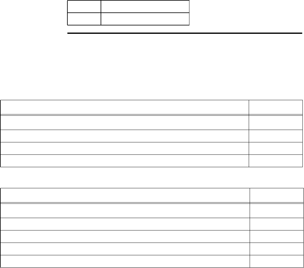
Configuring and Operating the Orion Reader Using TCP Commands
Use or disclosure of Proprietary Information contained on this sheet is subject to the restriction stated on the title page of this document. 6-87
Set Line Loss
This command sets the Orion Reader system line loss value from 0 to 3 dB. Table 6-
161 and Table 6-162 list the command and response data.
Note: This command should be set only after you set the RF attenuation(s).
4 Title 21
8 ISO 18000-6C (EPC)
Table 6-161 Set Line Loss Command (55H)
Set Line Loss Command Data Data Payload
Bits 7–0
Set Line Loss Command 55H
Line Loss Value (0, 1, 2, or 3) 0XH
Carriage Return 0DH
Table 6-162 Set Line Loss Response
Set Line Loss Response Data Data Payload
Bits 7–0
Set Line Loss Command 55H
Line Loss Value (0, 1, 2, or 3) 0XH
ACK or NACK, where ACK = 0 and NACK = 1 0XH
Carriage Return 0DH

Orion Reader System Guide
6-88 Use or disclosure of Proprietary Information contained on this sheet is subject to the restriction stated on the title page of this document.
Get Line Loss
This command gets the Orion Reader system line loss value. Table 6-163 and Table 6-
164 list the command and response data.
Set Uplink Source Control
The protocol-dependent Set Uplink Source Control command is used if the RF uplink
needs to use the RF downlink frequency, that is, Title 21 while running step-lock.
There are four uplink frequencies available. If more than four frequencies are needed,
then the Uplink Source Control command must be used to provide the remaining
needed frequencies with downlink frequency capability. Table 6-165 and Table 6-166
list the command and response data.
Table 6-163 Get Line Loss Command (56H)
Get Line Loss Command Data Data Payload
Bits 7–0
Get Line Loss Command 56H
Carriage Return 0DH
Table 6-164 Get Line Loss Response
Get Line Loss Response Data Data Payload
Bits 7–0
Get Line Loss Command 56H
Line Loss Value (0, 1, 2, or 3) 0XH
ACK or NACK, where ACK = 0 and NACK = 1 0XH
Carriage Return 0DH
Table 6-165 Set Uplink Source Control Command (57H)
Set Uplink Source Control Command Data Data Payload
Bit 7 Bit 6 Bit 5 Bit 4 Bit 3 Bit 2 Bit 1 Bit 0
Set Uplink Source Control Command 57H
Protocol Control XXH
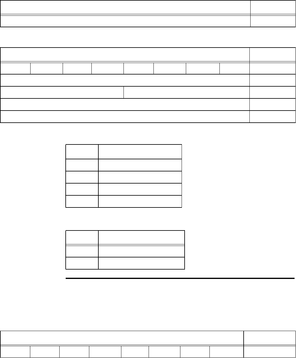
Configuring and Operating the Orion Reader Using TCP Commands
Use or disclosure of Proprietary Information contained on this sheet is subject to the restriction stated on the title page of this document. 6-89
Protocol — This field specifies the protocol for the Uplink Source Control command.
Control — This field specifies the protocol for the Uplink Source Control command.
Get Uplink Source Control
The Get Uplink Source Control command retrieves the source control information.
Table 6-167 and Table 6-168 list the command and response data.
Carriage Return 0DH
Table 6-166 Set Uplink Source Control Response
Set Uplink Source Response Data Data Payload
Bit 7 Bit 6 Bit 5 Bit 4 Bit 3 Bit 2 Bit 1 Bit 0
Set Uplink Source Control Command 57H
Protocol Control XXH
Acknowledge 00H
Carriage Return 0DH
Table 6-165 Set Uplink Source Control Command (57H)
Set Uplink Source Control Command Data Data Payload
Protocol Definition
2IAG
3 CVISN
4 Title 21
8 ISO 18000-6C (EPC)
Control Definition
0 Use Uplink Source (source 2)
1 Use Uplink Source (source 1)
Table 6-167 Get Uplink Source Control Command (58H)
Get Uplink Source Control Command Data Data Payload
Bit 7 Bit 6 Bit 5 Bit 4 Bit 3 Bit 2 Bit 1 Bit 0
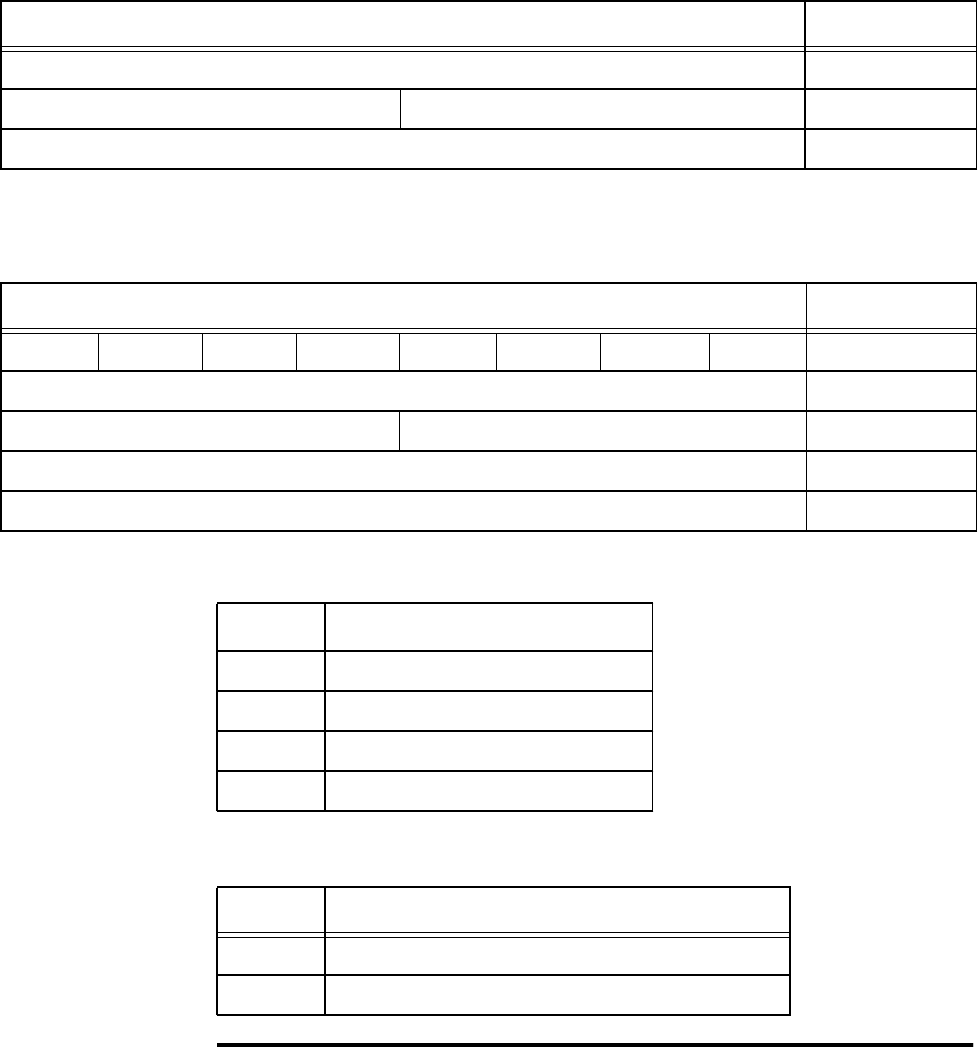
Orion Reader System Guide
6-90 Use or disclosure of Proprietary Information contained on this sheet is subject to the restriction stated on the title page of this document.
Protocol — This field specifies the protocol for the Source Control command
Control — This field specifies the Uplink Source.
Set Frequency in MHz
Note: Set the reader to Stop Mode 0 before issuing the Set Frequency in MHz com-
mand.
Get Uplink Source Control Command 58H
Protocol Control XXH
Carriage Return 0DH
Table 6-167 Get Uplink Source Control Command (58H)
Get Uplink Source Control Command Data Data Payload
Table 6-168 Get Uplink Source Control Response
Get Uplink Source Control Response Data Data Payload
Bit 7 Bit 6 Bit 5 Bit 4 Bit 3 Bit 2 Bit 1 Bit 0
Get Uplink Source Control Command 58H
Protocol Control XXH
Acknowledge 00H
Carriage Return 0DH
Protocol Definition
2IAG
3 CVISN
4 Title 21
8 ISO 18000-6C (EPC)
Control Definition
0 Uplink Source (source 2)
1 Uplink Source (source 1)
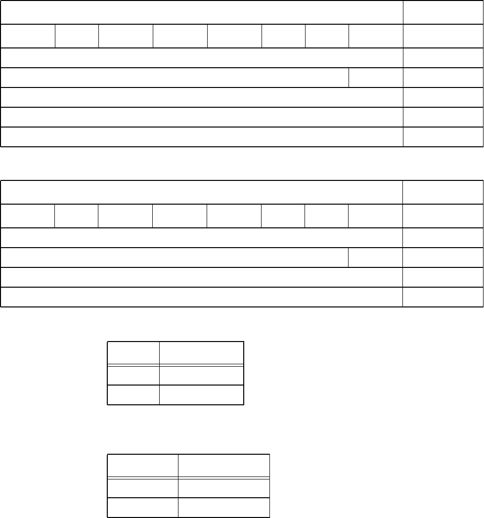
Configuring and Operating the Orion Reader Using TCP Commands
Use or disclosure of Proprietary Information contained on this sheet is subject to the restriction stated on the title page of this document. 6-91
This command is used to set the RF frequency of source 1 (downlink) and source2
(uplink). Table 6-169 and Table 6-170 list the command and response data.
Source — This field sets the source for the RF Frequency Control.
Frequency Control — Two-byte word to set frequency in 250-kHz steps starting at
800MHz. Examples of frequency settings are listed here.
Table 6-169 Set Frequency in MHz Command (60H)
Set Frequency in MHz Command Data Data Payload
Bit 7 Bit 6 Bit 5 Bit 4 Bit 3 Bit 2 Bit 1 Bit 0
Set Frequency in MHz Command 60H
Reserved Source 0XH
Frequency Control MSB XXH
Frequency Control LSB XXH
Carriage Return 0DH
Table 6-170 Set Frequency in MHz Rresponse
Set Frequency in MHz Response Data Data Payload
Bit 7 Bit 6 Bit 5 Bit 4 Bit 3 Bit 2 Bit 1 Bit 0
Set Frequency in MHz Command 60H
Reserved Source 0XH
Acknowledge 00H
Carriage Return 0DH
Protocol Definition
0 Source 1
1 Source 2
Setting Frequency
0118H 870.00 MHz
0198H 902.00 MHz

Orion Reader System Guide
6-92 Use or disclosure of Proprietary Information contained on this sheet is subject to the restriction stated on the title page of this document.
0199H 902.25 MHz
01E8H 922.00 MHz
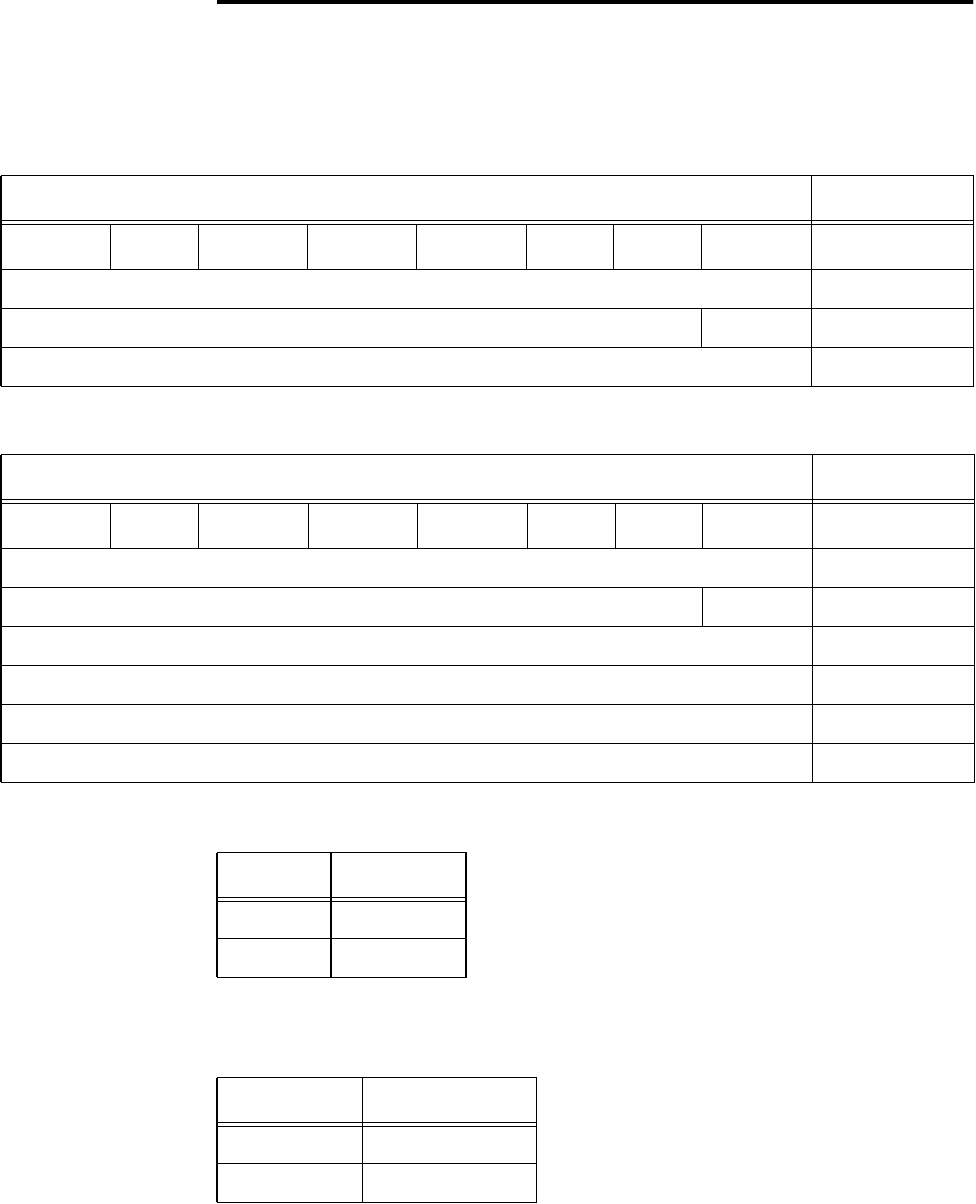
Configuring and Operating the Orion Reader Using TCP Commands
Use or disclosure of Proprietary Information contained on this sheet is subject to the restriction stated on the title page of this document. 6-93
Get Frequency in MHz
This command is used to get the RF frequency of source 1 (downlink) and source2
(uplink). Table 6-171 and Table 6-172 list the command and response data.
Source — This field sets the source for the RF Frequency Control
Frequency Control — Two-byte word to set frequency in 250-kHz steps starting
with 0000H at 800MHz. Examples of frequency settings are listed here.
Table 6-171 Get Frequency in MHz Command (61H)
Get Frequency in MHz Command Data Data Payload
Bit 7 Bit 6 Bit 5 Bit 4 Bit 3 Bit 2 Bit 1 Bit 0
Get Frequency in MHz Command 61H
Reserved Source 0XH
Carriage Return 0DH
Table 6-172 Get Frequency in MHz Response
Get Frequency in MHz Response Data Data Payload
Bit 7 Bit 6 Bit 5 Bit 4 Bit 3 Bit 2 Bit 1 Bit 0
Get Frequency in MHz Command 61H
Reserved Source 0XH
Frequency Control MSB XXH
Frequency Control LSB XXH
Acknowledge 00H
Carriage Return 0DH
Protocol Definition
0 Source 1
1 Source 2
Setting Frequency
0118H 870.00 MHz
0198H 902.00 MHz

Orion Reader System Guide
6-94 Use or disclosure of Proprietary Information contained on this sheet is subject to the restriction stated on the title page of this document.
Allowable Frequency Ranges by Protocol — There are permitted frequency ranges
that are protocol-dependent. When operating within North America, the following are
the approved defaulted uplink frequencies:
MIN_UL_FREQ1 902.25 MHz
MAX_UL_FREQ1 903.75 MHz
MIN_UL_FREQ2 910.00 MHz
MAX_UL_FREQ2 921.50 MHz
The downlink frequencies are protocol-dependent and are set to an allowable mini-
mum and maximum range. The frequency range combinations of protocols must be
set within these allowable frequency ranges.
IAG/CVSN MIN_FREQ 914.75 MHz
IAG/CVSN MAX_FREQ 916.75 MHz
T21 MIN_FREQ 912.75 MHz
T21 MAX_FREQ 918.75 MHz
0199H 902.25 MHz
01E8H 922.00 MHz

Configuring and Operating the Orion Reader Using TCP Commands
Use or disclosure of Proprietary Information contained on this sheet is subject to the restriction stated on the title page of this document. 6-95
Tag Transaction Configuration Command Group
Commands (1000H)
Table 6-173 lists the Tag Transaction Configuration Command Group commands that
are used in the Orion multiprotocol reader.
Table 6-173 Tag Transaction Configuration Command Group Commands
Tag Transaction Configuration Command Command
Code
Reserved 0000H to
0001H
Set Asynchronous Response Append Data 0002H
Get Asynchronous Response Append Data 0003H
Reserved 004H to
0024H
Set Manual Antenna Channel Control 002AH
Get Manual Antenna Channel Control 002BH
Get Configuration Table Version Number Command 002FH
Set IAG Slot 0030H
Get IAG Slot 0031H
Set Secondary Tag Sequence 0040H
Get Secondary Tag Sequence 0041H
Set Master/Slave Mode 0045H
Get Master/Slave Mode 0046H
Reserved 0047H to
0049H

Orion Reader System Guide
6-96 Use or disclosure of Proprietary Information contained on this sheet is subject to the restriction stated on the title page of this document.
Tag Transaction Configuration Command Group
Responses
Table 6-174 lists the responses and codes for the Tag Transaction Configuration com-
mand group.
Table 6-174 Tag Transaction Configuration Command Group Responses
Tag Transaction Configuration Response Response
Code
Synchronous OK Status Responses 88XXH
Reserved 8800H
Reserved 8801H
Asynchronous OK Status Responses 48XXH
Command Complete 4800H
Command In Progress 4801H
Unsolicited OK Status Responses 28XXH
Reserved 84XXH
Reserved 44XXH
Reserved 24XXH
Synchronous Error Status Responses 82XXH
Message Length Error 8200H
Message Sequence Error 8201H
Reserved 8202H
Command Group Error 8203H
Reserved 8204H
Reserved 8205H

Configuring and Operating the Orion Reader Using TCP Commands
Use or disclosure of Proprietary Information contained on this sheet is subject to the restriction stated on the title page of this document. 6-97
Reserved 8206H
Reserved 8207H
Reserved 8208H
Data Acknowledge Response Error 8209H
Reserved 820AH
Asynchronous Error Status Responses 42XXH
Message Length Error 4200H
Command Sequence Error 4201H
Message Queue Full Error 4202H
Command Group Error 4203H
Command Time-out Error 4204H
Command Nack Error 4205H
Command Failed Error 4206H
System Command Error 4207H
Sub-Command Error 4208H
Data Acknowledge Time-out Error 4209H
Invalid Control Word Error 420AH
Invalid Command Data Error System 420BH
Unsolicited Error Status Responses 22XXH
Synchronous Control Status Responses 81XXH
Data Acknowledge (Ack), data valid 8100H
Data Negative Acknowledge (Nack), data invalid 8101H
Reserved 8102H
Reserved 8104H
Table 6-174 Tag Transaction Configuration Command Group Responses
Tag Transaction Configuration Response Response
Code

Orion Reader System Guide
6-98 Use or disclosure of Proprietary Information contained on this sheet is subject to the restriction stated on the title page of this document.
Tag Transaction Configuration Command Group Response
Data
Asynchronous OK Status Responses
The following tag transaction configuration command group asynchronous OK status
responses use the specified data payload.
Command Complete (4800H)
Command In Progress (4801H)
Synchronous Error Status Responses
The following tag transaction configuration command group synchronous error status
responses use the specified data payload.
Asynchronous Control Status Responses 41XXH
Unsolicited Control Status Responses 21XXH
Command In Progress Response Data Data
Payload
TTC Command Group Command (sub-command) XXXXH
Command In Progress Response Data Data
Payload
TTC Command Group Command (sub-command) XXXXH
Table 6-174 Tag Transaction Configuration Command Group Responses
Tag Transaction Configuration Response Response
Code

Configuring and Operating the Orion Reader Using TCP Commands
Use or disclosure of Proprietary Information contained on this sheet is subject to the restriction stated on the title page of this document. 6-99
Message Length Error Response Data (8200H)
Message Sequence Error Response Data (8201H)
Command Group Error Response Data (8203H)
Data Acknowledge Response Error Response Data (8209H)
Asynchronous Error Status Responses
The following tag transaction configuration command group asynchronous error sta-
tus responses use the specified data payload.
Message Length Error Response Data Data
Payload
Expected Message Length XXXXH
Received Message Length XXXXH
Message Sequence Error Response Data Data
Payload
Expected Message Sequence Number XXH
Received Message Sequence Number XXH
Command Group Error Response Data Data
Payload
Invalid Command Group XXXXH
Data Acknowledge Response Error Response Data Data
Payload
Invalid Data Acknowledge Response XXXXH

Orion Reader System Guide
6-100 Use or disclosure of Proprietary Information contained on this sheet is subject to the restriction stated on the title page of this document.
Message Length Error Response Data (4200H)
Command Sequence Error Response Data (4201H)
Command Group Error (4203H)
Command Time-out Error (4204H)
Command Failed Error (4206H)
System Command Error (4207H)
Message Length Error Response Data Data
Payload
Expected Message Length XXXXH
Received Message Length XXXXH
Command Sequence Error Response Data Data
Payload
Expected Command Sequence Number XXH
Received Command Sequence Number XXH
Command Group Error Response Data Data
Payload
Invalid Command Group XXXXH
Command Time-out Error Response Data Data
Payload
N/A
Command Failed Error Response Data Data
Payload
TTC Command Group Command (sub-command)
XXXXH
System Command Error Response Data Data
Payload
N/A
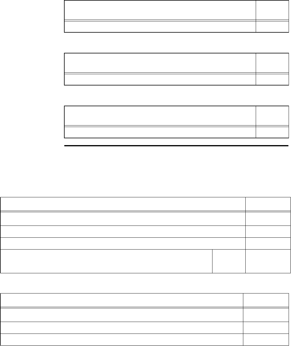
Configuring and Operating the Orion Reader Using TCP Commands
Use or disclosure of Proprietary Information contained on this sheet is subject to the restriction stated on the title page of this document. 6-101
Sub-Command Error (4208H)
Invalid Control Word Error (420AH)
Invalid Command Data Error System (420BH)
Set Asynchronous Response Append Data
This command sets the append time-stamp data control parameter for all asynchro-
nous tag responses. Table 6-175 and Table 6-176 list the command and response data.
Sub-Command Error Response Data Data
Payload
Sub-command XXXXH
Invalid Control Word Error Response Data Data
Payload
N/A
Invalid Command Data Error System Response Data Data
Payload
N/A
Table 6-175 Set Asynchronous Response Append Data Command (0002H)
Set Asynchronous Response Append Command Data Payload
Bits 7–0
Set Asynchronous Response Append Data Command (MSB) 00H
Set Asynchronous Response Append Data Command (LSB) 02H
Reserved Append
Data
Control
0XH
Table 6-176 Set Asynchronous Response Append Data Response
Set Asynchronous Response Append Data Response Data Payload
Bits 7–0
Set Asynchronous Response Append Data Command (MSB) 00H
Set Asynchronous Response Append Data Command (LSB) 02H
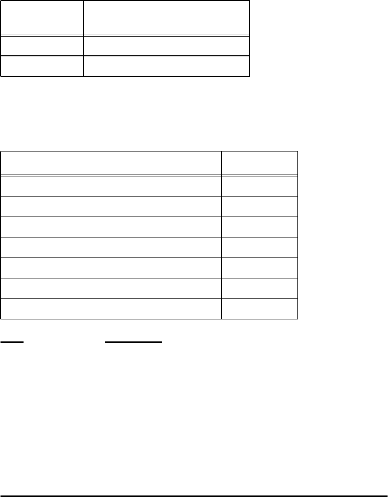
Orion Reader System Guide
6-102 Use or disclosure of Proprietary Information contained on this sheet is subject to the restriction stated on the title page of this document.
Append data control — This field controls whether the date and time-stamp is
appended to all tag asynchronous responses.
Formats forTime and Date Time-stamp
Table 6-177 lists the time and date time-stamp formats.
Data Data Range
Hours 0 to 23 (00H to 17H)
Minutes 0 to 59 (00H to 3BH)
Seconds 0 to 59 (00H to 3BH)
Hundredths of seconds0 to 99 (00H to 63H)
Month 1 to 12 (01H to 0CH)
Day 1 to 31 (01H to 1FH)
Year 0 to 99 (00H to 63H)
Get Asynchronous Response Append Data
This command gets the append time-stamp data control parameter for all
asynchronous tag responses. Table 6-178 and Table 6-179 list the command and
response data.
Append Data
Control Definition
0 Disable
1 Append time and date time-stamp
Table 6-177 Time and Date Time-Stamp Formats
Time and Date Time-stamp Format Data Payload
Hours XXH
Minutes XXH
Seconds XXH
Hundredths of Seconds XXH
Month XXH
Day XXH
Year XXH

Configuring and Operating the Orion Reader Using TCP Commands
Use or disclosure of Proprietary Information contained on this sheet is subject to the restriction stated on the title page of this document. 6-103
Append Data Control — This field controls whether the time and date time-stamp is
appended to all tag asynchronous responses.
Table 6-178 Get Asynchronous Response Append Data Command (0003H)
Get Asynchronous Response Append Data Response Data Payload
Bits 7–0
Get Asynchronous Response Append Data Command (MSB) 00H
Get Asynchronous Response Append Data Command (LSB) 03H
Table 6-179 Get Asynchronous Response Append Data Response
Get Asynchronous Response Append Command Data Payload
Bit 7 Bit 6 Bit 5 Bit 4 Bit 3 Bit 2 Bit 1 Bit 0
Get Asynchronous Response Append Data Command (MSB) 00H
Get Asynchronous Response Append Data Command (LSB) 03H
Reserved Append
Data
Control
0XH
Append Data
Control Definition
0 Disable
1 Append time and date time-stamp
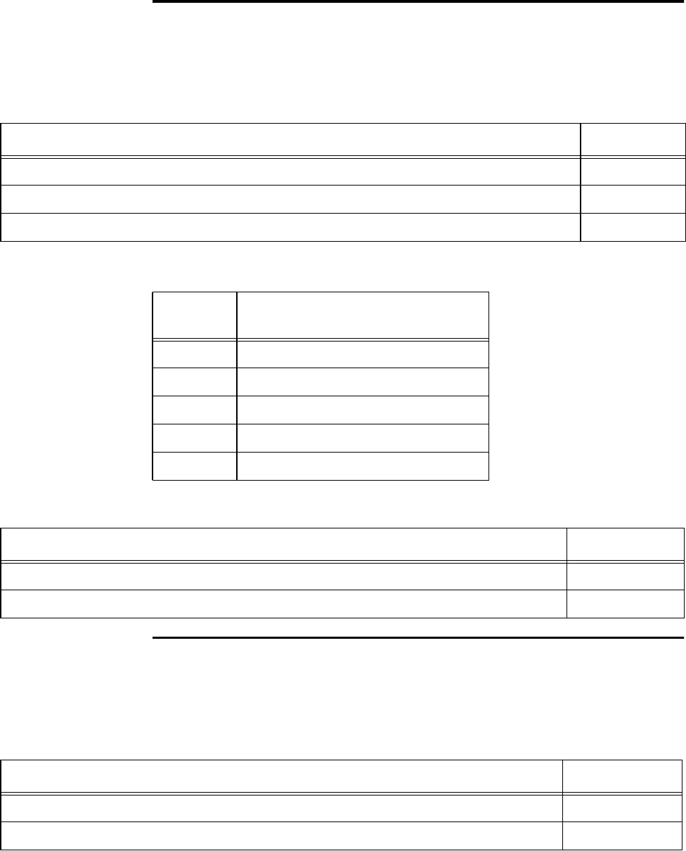
Orion Reader System Guide
6-104 Use or disclosure of Proprietary Information contained on this sheet is subject to the restriction stated on the title page of this document.
Set Manual Antenna Channel Control
This command sets the reader’s manual antenna channel control. Table 6-180 and
Table 6-181 list the command and response data.
The channel control definitions are as follows:
Get Manual Antenna Channel Control
This command gets the reader’s manual antenna channel control. Table 6-182 and
Table 6-183 list the command and response data.
Table 6-180 Set Manual Antenna Channel Control Command (002AH)
Set Manual Antenna Channel Control Command Data Payload
Bits 7–0
Set Manual Antenna Channel Control Command 002AH
Channel Control 0XH
Channel
Control Definition
01H Channel 0 on
02H Channel 1 on
03H Channel 2 on
04H Channel 3 on
05H Disable manual channel control
Table 6-181 Set Manual Antenna Channel Control Response
Set Manual Antenna Channel Control Response Data Data Payload
Bits 7–0
Set Manual Antenna Channel Control Command 002AH
Table 6-182 Get Manual Antenna Channel Control Command (002BH)
Get Manual Antenna Channel Control Command Data Payload
Bits 7–0
Get Manual Antenna Channel Control Command 002BH
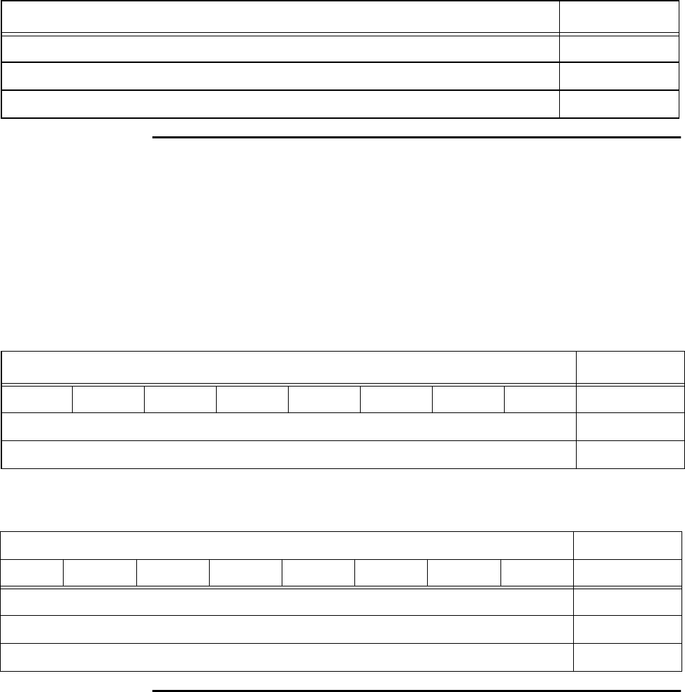
Configuring and Operating the Orion Reader Using TCP Commands
Use or disclosure of Proprietary Information contained on this sheet is subject to the restriction stated on the title page of this document. 6-105
Get Universal Configuration Table Version Number
This command returns the version number of the Universal Configuration Table. It is
one of two commands that are used in the Orion Reader to help support a single con-
figuration file. Table 6-184 and Table 6-185 list the command and response data.
Precondition: None
Post Condition: Command takes effect immediately.
Set IAG Slot
Table 6-183 Get Manual Antenna Channel Control Response
Get Manual Antenna Channel Control Response Data Data Payload
Bits 7–0
Get Manual Antenna Channel Control Command 002BH
Channel Control 0XH
Table 6-184 Get Universal ConfigurationTable Version Number Command (002FH)
Get Universal Configuration Table Version Number Command Data Data Payload
Bit 7 Bit 6 Bit 5 Bit 4 Bit 3 Bit 2 Bit 1 Bit 0
Get Universal Configuration Table Version Number Command (MSB) 00H
Get Universal Configuration Table Version Number Command (LSB) 2FH
Table 6-185 Get Universal ConfigurationTable Version Number Response
Get Universal Configuration Table Version Number Response Data Data Payload
Bit 7 Bit 6 Bit 5 Bit 4 Bit 3 Bit 2 Bit 1 Bit 0
Get Universal Configuration Table Version Number Command (MSB) 00H
Get Universal Configuration Table Version Number Command (LSB) 2FH
Universal Configuration Table Version XXH x 13

Orion Reader System Guide
6-106 Use or disclosure of Proprietary Information contained on this sheet is subject to the restriction stated on the title page of this document.
The Set IAG Slot Command configures the downlink values used with IAG modes.
Table 6-186 and Table 6-187 list the command and response data.
Slot — The value of the downlink slot for setting up the IAG sequence, the value can
be 1, 2, or 3.
1 = Downlink on slots 1 and 4
2 = Downlink on slots 2 and 5
3 = Downlink on slots 3 and 6
Get IAG Slot
The Get IAG Slot command returns the downlink values used with IAG modes. Table
6-188 and Table 6-189 list the command and response data.
Table 6-186 Set IAG Slot Command (0030H)
Set IAG Slot Command Data Data Payload
Bits 7–0
Set IAG Slot Command (MSB) 00H
Set IAG Slot Command (LSB) 30H
Slot 0XH
Table 6-187 Set IAG Slot Response
Set IAG Slot Response Data Data Payload
Bits 7–0
Set IAG Slot Command (MSB) 00H
Set IAG Slot Command (LSB) 30H
Table 6-188 Get IAG Slot Command (0031H)
Get IAG Slot Command Data Data Payload
Bits 7–0
Get IAG Slot Command (MSB) 00H
Get IAG Slot Command (LSB) 31H
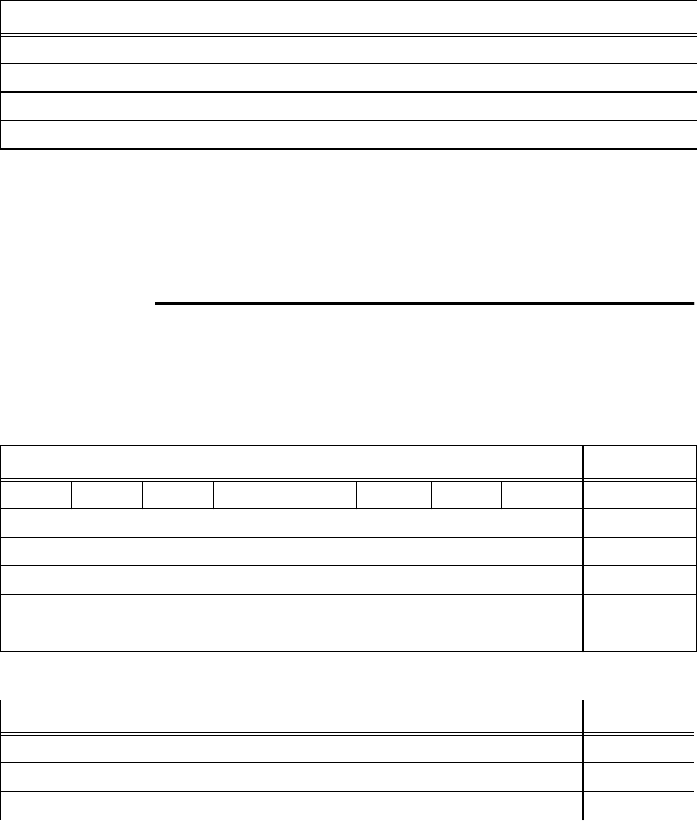
Configuring and Operating the Orion Reader Using TCP Commands
Use or disclosure of Proprietary Information contained on this sheet is subject to the restriction stated on the title page of this document. 6-107
Slot — The value of the downlink slot for setting up the IAG sequence, the value can
be 1, 2, or 3.
1 = Slots 1 and 4
2 = Slots 2 and 5
3 = Slots 3 and 6
Set Secondary Tag Sequence
The Set Secondary Tag Sequence Command specifies which tag sequence to run,
which allows the user to select from a set of protocols and the respective Ack/No Ack.
Table 6-190 and Table 6-191 list the command and response data.
Table 6-189 Get IAG Slot Command Data Response
Get IAG Slot Response Data Data Payload
Bits 7–0
Get IAG Slot Command (MSB) 00H
Get IAG Slot Command (LSB) 31H
Slot 0XH
Table 6-190 Set Secondary Tag Sequence Command (0040H)
Set Secondary Tag Sequence Command Data Data Payload
Bit 7 Bit 6 Bit 5 Bit 4 Bit 3 Bit 2 Bit 1 Bit 0
Set Secondary Tag Sequence Command (MSB) 00H
Set Secondary Tag Sequence Command (LSB) 40H
Reserved 00H
Protocol ID Configuration ID XXH
Antenna Number 0XH
Table 6-191 Set Secondary Tag Sequence Response
Set Secondary Tag Sequence Response Data Data Payload
Bits 7–0
Set Secondary Tag Sequence Command (MSB) 00H
Set Secondary Tag Sequence Command (LSB) 40H
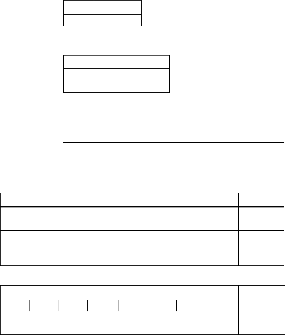
Orion Reader System Guide
6-108 Use or disclosure of Proprietary Information contained on this sheet is subject to the restriction stated on the title page of this document.
Protocol — This field sets the protocol for the secondary tag sequence.
Configuration ID — This field sets the configuration ID for IT2200 and Title 21 pro-
tocols.
Antenna Number — This field specifies the antenna number, which ranges from 0 to
03H.
Note: Reset the Orion Reader after setting the secondary tag sequence. See “Reset
Reader” on page 6-24 for command information.
Get Secondary Tag Sequence
The Get Secondary Tag Sequence Command retrieves the tag sequence. Table 6-192
and Table 6-193 list the command and response data.
Protocol Definition
4 Title 21
Configuration ID Definition
0NoAck
1Ack
Table 6-192 Get Secondary Tag Sequence Command (0041H)
Get Secondary Tag Sequence Command Data Data Payload
Bits 7–0
Get Secondary Tag Sequence Command (MSB) 00H
Get Secondary Tag Sequence Command (LSB) 41H
Protocol ID 0XH
Antenna Number 0XH
Table 6-193 Get Secondary Tag Sequence Response
Get Secondary Tag Sequence Response Data Data Payload
Bit 7 Bit 6 Bit 5 Bit 4 Bit 3 Bit 2 Bit 1 Bit 0
Get Secondary Tag Sequence Command (MSB) 00H
Get Secondary Tag Sequence Command (LSB) 41H
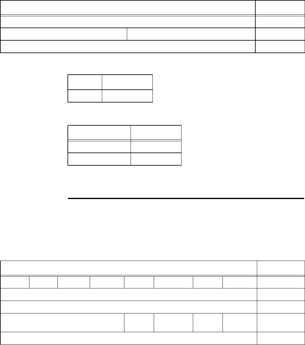
Configuring and Operating the Orion Reader Using TCP Commands
Use or disclosure of Proprietary Information contained on this sheet is subject to the restriction stated on the title page of this document. 6-109
Protocol — This field gets the protocol for the secondary tag sequence.
Configuration ID — This field gets the configuration ID for IT2200 and Title 21 protocols.
Antenna Number — This field gets the antenna number, which ranges from 0 to
03H.
Set Master/Slave Mode
The Set Master/Slave Mode Command specifies which reader to set as master, which
then enables all other readers as slaves. Table 6-194 and Table 6-195 list the command
and response data.
Reserved 00H
Protocol ID Configuration ID XXH
Antenna Number 0XH
Table 6-193 Get Secondary Tag Sequence Response
Get Secondary Tag Sequence Response Data Data Payload
Protocol Definition
4 Title 21
Configuration ID Definition
0NoAck
1Ack
Table 6-194 Set Master/Slave Mode Command (0045H)
Set Master/Slave Mode Command Data Data Payload
Bit 7 Bit 6 Bit 5 Bit 4 Bit 3 Bit 2 Bit 1 Bit 0
Set Master/Slave Mode Command (MSB) 00H
Set Master/Slave Mode Command (LSB) 45H
Reserved GPS
Primary GPS
Secondary Master Slave 0XH
Slave Select Count XXH
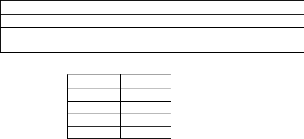
Orion Reader System Guide
6-110 Use or disclosure of Proprietary Information contained on this sheet is subject to the restriction stated on the title page of this document.
Mode — This field sets the protocol for the secondary tag sequence.
Note: *Select only one mode from this list.
Choose one field only, for example, GPS primary, GPS secondary, master, or slave.
GPS Primary — This field specifies whether the reader is to be configured as the
GPS primary.
GPS Secondary — This field specifies whether the reader is to be configured as the
GPS secondary.
Master — This field specifies whether the reader is to be configured as the master.
Table 6-195 Set Master/Slave Mode Response
Set Master/Slave Mode Response Data Data Payload
Bits 7–0
Set Master/Slave Mode Command (MSB) 00H
Set Master/Slave Mode Command (LSB) 45H
Mode* Data Payload
Slave 01
Master 02
GPS Secondary 04
GPS Primary 08
GPS Primary Definition
0 Not GPS Primary
1 GPS Primary
GPS Secondary Definition
0 Not GPS Secondary
1 GPS Secondary
Master Definition

Configuring and Operating the Orion Reader Using TCP Commands
Use or disclosure of Proprietary Information contained on this sheet is subject to the restriction stated on the title page of this document. 6-111
Slave — This field specifies whether the reader is to be configured as the slave.
For this example, the sum of the delay and duration period is 19.9 milliseconds, which
is less than the synchronization rate of 20 milliseconds. If the sum of the delay and
duration periods equals the synchronization rate, unexpected results can occur.
Slave Select Count — This field specifies the order that a slave or GPS primary or
secondary reader issues a synchronization pulse whenever a given reader within a syn-
chronization group fails to recognize the signal from the preassigned master or when-
ever a GPS receiver fails to issue a 1-pps signal, respectively. The maximum slave
count = 26.
Scenario 1 — One master, n slaves. The master has no slave behavior, therefore it is
assigned a slave select count of 0. Each slave is assigned an increasingly greater num-
ber from 1 to n. When the master fails, slave 1 becomes the master, and so on.
Scenario 2 — GPS primary, GPS secondary, N slave readers. When in fault mode (1-
pps signal missing), a GPS primary is slave to a GPS secondary and all other slaves
and is assigned the last slave select count, n. A GPS secondary takes over when a GPS
primary is in fault mode, therefore it is assigned a slave select count of 1. All slaves
are assigned increasingly greater numbers from 2 to n+1.
Scenario 3 — One GPS primary and n slaves. This scenario forces the GPS primary
to have no slave behavior by specifying a slave select count of 0. Each slave is an
increasingly higher number from 1 to n. When the master fails, slave 1 becomes the
master. If slave 1 should fail, slave 2 takes over, and so on (Table 6-196).
0 Not Master
1 Master
Slave Definition
0 Not Slave
1 Slave
Table 6-196 Reader Slave ConfigurationTable
Scenario 1 —One Master, n Slaves
Reader Mode Master Slave Slave Slave Slave Slave
Slave Select Count 0 1 2 … n-1 n
Scenario 2 —GPS Primary, GPS Secondary, n Slaves
Reader Mode GPS
Secondary Slave Slave Slave Slave GPS
Primary
Slave Select Count 1 2 3 … n+1 n+2
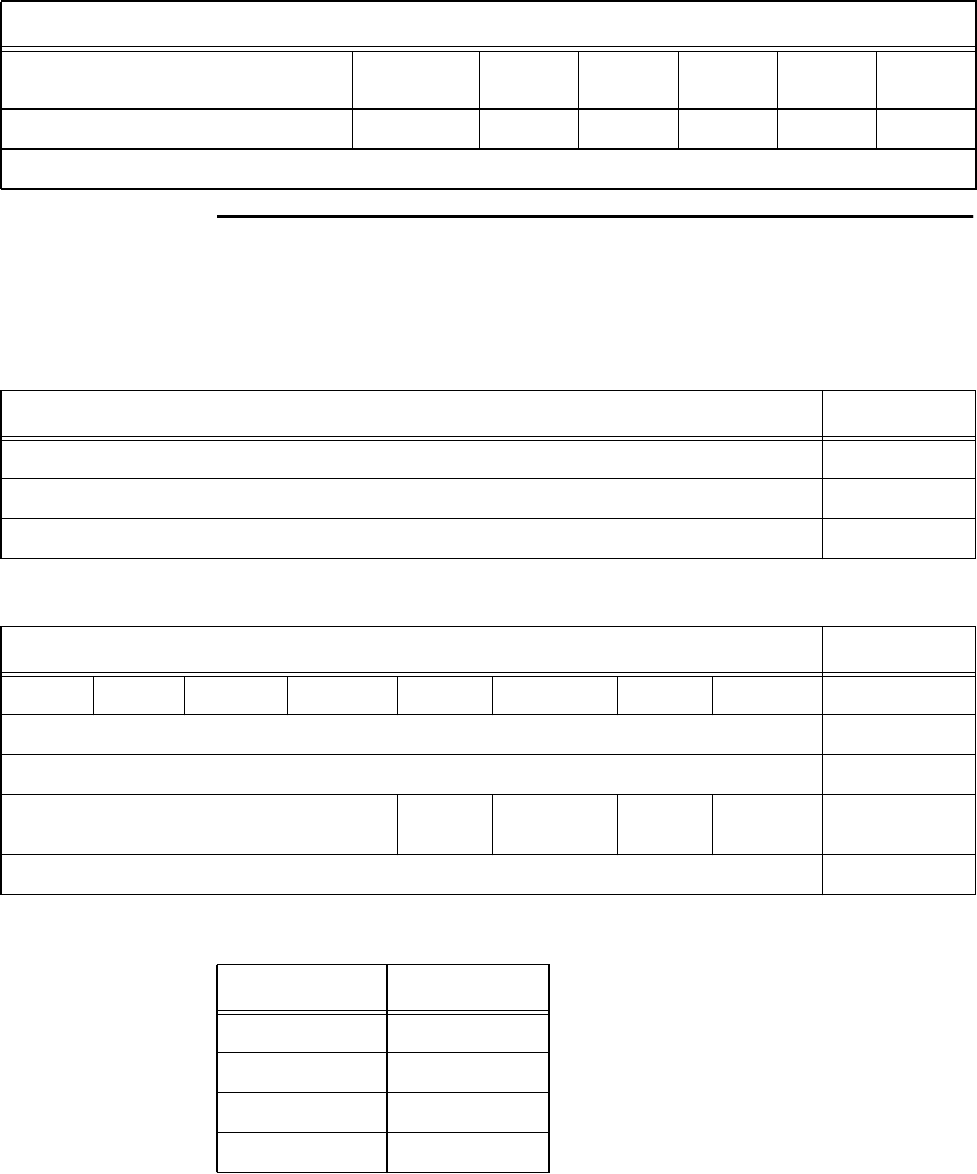
Orion Reader System Guide
6-112 Use or disclosure of Proprietary Information contained on this sheet is subject to the restriction stated on the title page of this document.
Get Master/Slave Mode
The Get Master/Slave Mode Command retrieves the reader that is set as master. Table
6-197 and Table 6-198 list the command and response data.
Mode — This field sets the protocol for the secondary tag sequence.
Scenario 3 —One GPS Primary, n Slaves
Reader Mode GPS
Primary Slave Slave Slave Slave Slave
Slave Select Count 0 1 2 … n-1 n
n = Total number of slave readers
Table 6-196 Reader Slave ConfigurationTable
Table 6-197 Get Master/Slave Mode Command (0046H)
Get Master/Slave Mode Command Data Data Payload
Bits 7–0
Get Master/Slave Mode Command (MSB) 00H
Get Master/Slave Mode Command (LSB) 46H
Table 6-198 Get Master/Slave Mode Response Data
Get Master/Slave Mode Response Data Data Payload
Bit 7 Bit 6 Bit 5 Bit 4 Bit 3 Bit 2 Bit 1 Bit 0
Get Master/Slave Mode Command (MSB) 00H
Get Master/Slave Mode Command (LSB) 46H
Reserved GPS
Primary GPS
Secondary Master Slave 0XH
Slave Select Count XXH
Mode* Data Payload
Slave 01
Master 02
GPS Secondary 04
GPS Primary 08
Configuring and Operating the Orion Reader Using TCP Commands
Use or disclosure of Proprietary Information contained on this sheet is subject to the restriction stated on the title page of this document. 6-113
Note: *Select only one mode from this list.
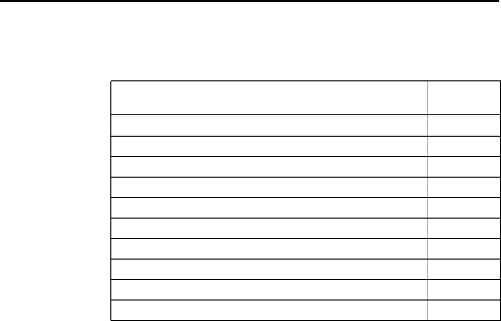
Orion Reader System Guide
6-114 Use or disclosure of Proprietary Information contained on this sheet is subject to the restriction stated on the title page of this document.
Mode Command Group Commands (0400H)
Table 6-199 lists the Mode Command Group commands that are used to configure and
operate the Orion multiprotocol reader in any of the modes.
Table 6-199 Mode Command Group Commands
Mode Command Group Command Command
Code
Set Mode 0001H
Get Mode 0002H
Set Protocol 0003H
Get Protocol 0004H
CVISN Enforcement Last Tag Status Reset 0043H
Set ISO 18000-6C (EPC) Configuration Data 0043H
Reserved 0052H
Reserved 0053H
Set Seen Count 0066H
Get Seen Count 0067H

Configuring and Operating the Orion Reader Using TCP Commands
Use or disclosure of Proprietary Information contained on this sheet is subject to the restriction stated on the title page of this document. 6-115
Mode Command Group Responses
Table 6-200 lists the responses and codes for the Mode command group.
Table 6-200 Mode Command Group Responses
Mode Command Group Responses Response
Code
Synchronous OK Status Responses 88XXH
Reserved 8800H
Reserved 8801H
Asynchronous OK Status Responses 48XXH
Command Complete 4800H
Command In Progress 4801H
Unsolicited OK Status Responses 28XXH
Reserved 84XXH
Reserved 44XXH
Reserved 24XXH
Synchronous Error Status Responses 82XXH
Message Length Error 8200H
Message Sequence Error 8201H
Reserved 8202H
Command Group Error 8203H
Reserved 8204H
Reserved 8205H
Reserved 8206H
Reserved 8207H

Orion Reader System Guide
6-116 Use or disclosure of Proprietary Information contained on this sheet is subject to the restriction stated on the title page of this document.
Reserved 8208H
Data Acknowledge Response Error 8209H
Reserved 820AH
Asynchronous Error Status Responses 42XXH
Message Length Error 4200H
Command Sequence Error 4201H
Reserved 4202H
Command Group Error 4203H
Command Time-out Error 4204H
Reserved 4205H
Command Failed Error 4206H
System Command Error 4207H
Sub-Command Error 4208H
Reserved 4209H
Invalid Control Word Error 420AH
Invalid Command Data Error System 420BH
Unsolicited Error Status Responses 22XXH
Synchronous Control Status Responses 81XXH
Data Acknowledge (Ack), data valid 8100H
Data Negative Acknowledge (Nack), data invalid 8101H
Reserved 8102H
Reserved 8104H
Asynchronous Control Status Responses 41XXH
Table 6-200 Mode Command Group Responses
Mode Command Group Responses Response
Code

Configuring and Operating the Orion Reader Using TCP Commands
Use or disclosure of Proprietary Information contained on this sheet is subject to the restriction stated on the title page of this document. 6-117
Table 6-201 lists the mode command group asynchronous response codes and record
types.
Unsolicited Control Status Responses 21XXH
Table 6-201 Mode Command Group Asynchronous Responses
Mode Command Group Asynchronous Response Response
Code Record
Type
Reserved 4800H 3020H
Read Verify Page 4800H 3022H
Title 21 Read Response 4800H 3024H
Seen Frame Counter Error Report 4204H 3042H
Seen Frame Counter Report 4800H 3043H
Reserved 4204H 3044H
Reserved 4800H 2303H
Reserved 4204H 3040H
Reserved 4204H 3041H
CVISN Read Response 4800H 5014H
Reserved 4800H 5013H
IAG Read 5026H
IAG Cross-Lane Read 5027H
Table 6-200 Mode Command Group Responses
Mode Command Group Responses Response
Code

Orion Reader System Guide
6-118 Use or disclosure of Proprietary Information contained on this sheet is subject to the restriction stated on the title page of this document.
Mode Command Group Response Data
Asynchronous OK Status Responses
The following mode command group asynchronous OK status responses use the spec-
ified data payload.
Command Complete (4800H)
Command In Progress (4801H)
Synchronous Error Status Responses
The following mode command group synchronous error status responses use the spec-
ified data payload.
Command In Progress Response Data Data
Payload
Mode Command Group Command (sub-command) XXXXH
Command In Progress Response Data Data
Payload
Mode Command Group Command (sub-command) XXXXH

Configuring and Operating the Orion Reader Using TCP Commands
Use or disclosure of Proprietary Information contained on this sheet is subject to the restriction stated on the title page of this document. 6-119
Message Length Error Response Data (8200H)
Message Sequence Error Response Data (8201H)
Command Group Error Response Data (8203H)
Data Acknowledge Response Error Response Data (8209H)
Asynchronous Error Status Responses
The following mode command group asynchronous error status responses use the
specified data payload.
Message Length Error Response Data Data
Payload
Expected Message Length XXXXH
Received Message Length XXXXH
Message Sequence Error Response Data Data
Payload
Expected Message Sequence Number XXH
Received Message Sequence Number XXH
Command Group Error Response Data Data
Payload
Invalid Command Group XXXXH
Data Acknowledge Response Error Response Data Data
Payload
Invalid Data Acknowledge Response XXXXH

Orion Reader System Guide
6-120 Use or disclosure of Proprietary Information contained on this sheet is subject to the restriction stated on the title page of this document.
Message Length Error Response Data (4200H)
Command Sequence Error Response Data (4201H)
Command Group Error (4203H)
Command Time-out Error (4204H)
Command Failed Error (4206H)
System Command Error (4207H)
Message Length Error Response Data Data
Payload
Expected Message Length XXXXH
Received Message Length XXXXH
Command Sequence Error Response Data Data
Payload
Expected Command Sequence Number XXH
Received Command Sequence Number XXH
Command Group Error Response Data Data
Payload
Invalid Command Group XXXXH
Command Time-out Error Response Data Data
Payload
N/A
Command Failed Error Response Data Data
Payload
Mode Command Group Command (sub-command) XXXXH
System Command Error Response Data Data
Payload
N/A
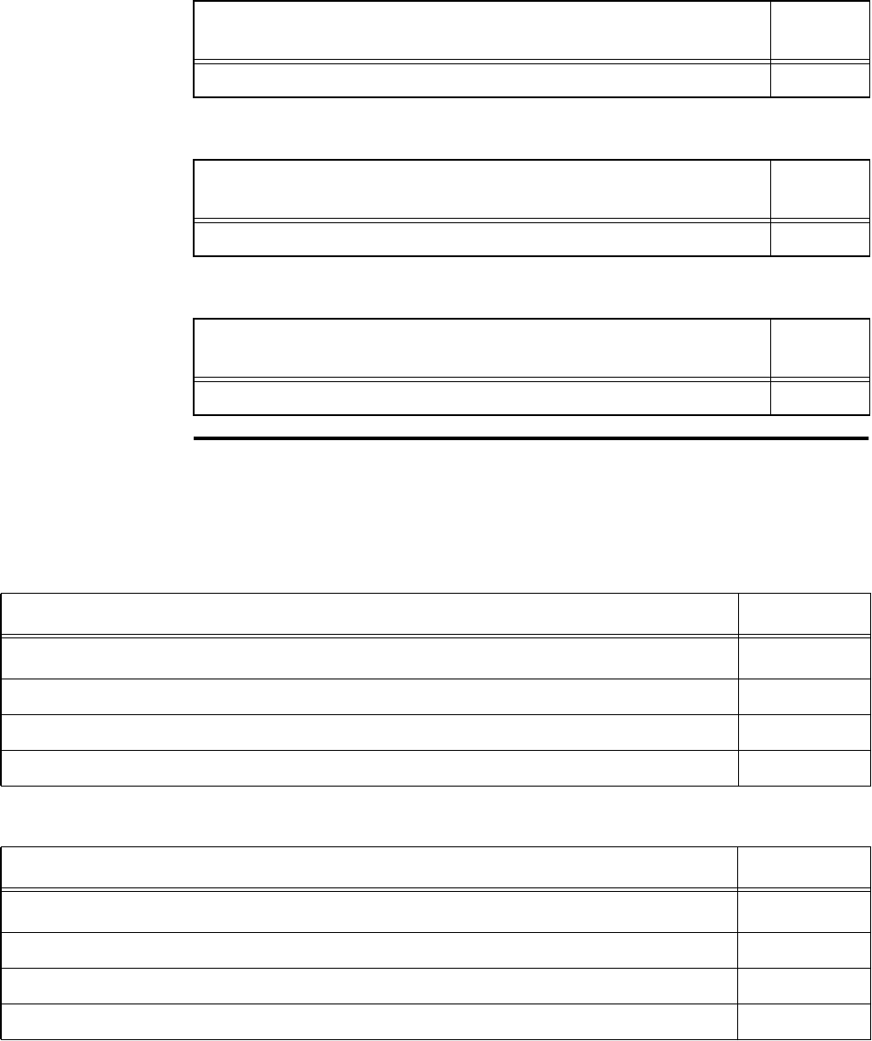
Configuring and Operating the Orion Reader Using TCP Commands
Use or disclosure of Proprietary Information contained on this sheet is subject to the restriction stated on the title page of this document. 6-121
Sub-Command Error (4208H)
Invalid Control Word Error (420AH)
Invalid Command Data Error (420BH)
Set Mode
This command sets the Orion Reader to mode 88. Table 6-202 and Table 6-203 list the
command and response data.
Sub-Command Error Response Data Data
Payload
Sub-command XXXXH
Invalid Control Word Error Response Data Data
Payload
N/A
Invalid Command Data Error Response Data Data
Payload
N/A
Table 6-202 Set Mode Command (0001H)
Set Mode Command Data Data Payload
Bits 7–0
Set Mode Command (MSB) 00H
Set Mode Command (LSB) 01H
Mode Number 58H
Table 6-203 Set Mode Response
Set Mode Command Response Data Data Payload
Bits 7–0
Set Mode Command (MSB) 00H
Set Mode Command (LSB) 02H
Mode Number 58H

Orion Reader System Guide
6-122 Use or disclosure of Proprietary Information contained on this sheet is subject to the restriction stated on the title page of this document.
Mode Number — This field identifies mode as 88.
Note: RESET READER command required for changes to take effect.
Get Mode
This command gets the Orion Reader mode. Table 6-204 and Table 6-205 list the
command and response data.
Mode Number — This field identifies mode as 88.
Table 6-204 Get Mode Command (0002H)
Get Mode Command Data Data Payload
Bits 7–0
Get Mode Command (MSB) 00H
Get Mode Command (LSB) 02H
Table 6-205 Get Mode Command Response
Get Mode Command Response Data Data Payload
Bits 7–0
Get Mode Command (MSB) 00H
Get Mode Command (LSB) 02H
Mode Number 58H

Configuring and Operating the Orion Reader Using TCP Commands
Use or disclosure of Proprietary Information contained on this sheet is subject to the restriction stated on the title page of this document. 6-123
Set Protocol
This command configures the Orion Reader to enable specified protocols. Table 6-206
and Table 6-207 list the command and response data.
Note: Reset the Orion Reader after setting the protocol. See “Reset Reader” on page
6-24 for command information.
Protocols — These fields specify the protocol to enable. The example shows two
enabled protocols.
Note: RESET READER command required for changes to take effect.
Table 6-206 Set Protocol Command (0003H)
Set Protocol Command Data Data Payload
Bits 7–0
Set Protocol Command (MSB) 00H
Set Protocol Command (LSB) 03H
Reserved 6C (EPC) CVISN IAG Rsvd 0XH
IAG Read Title 21 Reserved XXH
Table 6-207 Set Protocol Response
Set Protocol Response Data Data Payload
Bits 7–0
Set Protocol Command (MSB) 00H
Set Protocol Command (LSB) 03H
All protocols off 0000H
Enabling two protocols:
6C (EPC) 0800H
Title 21 0008H
0808H
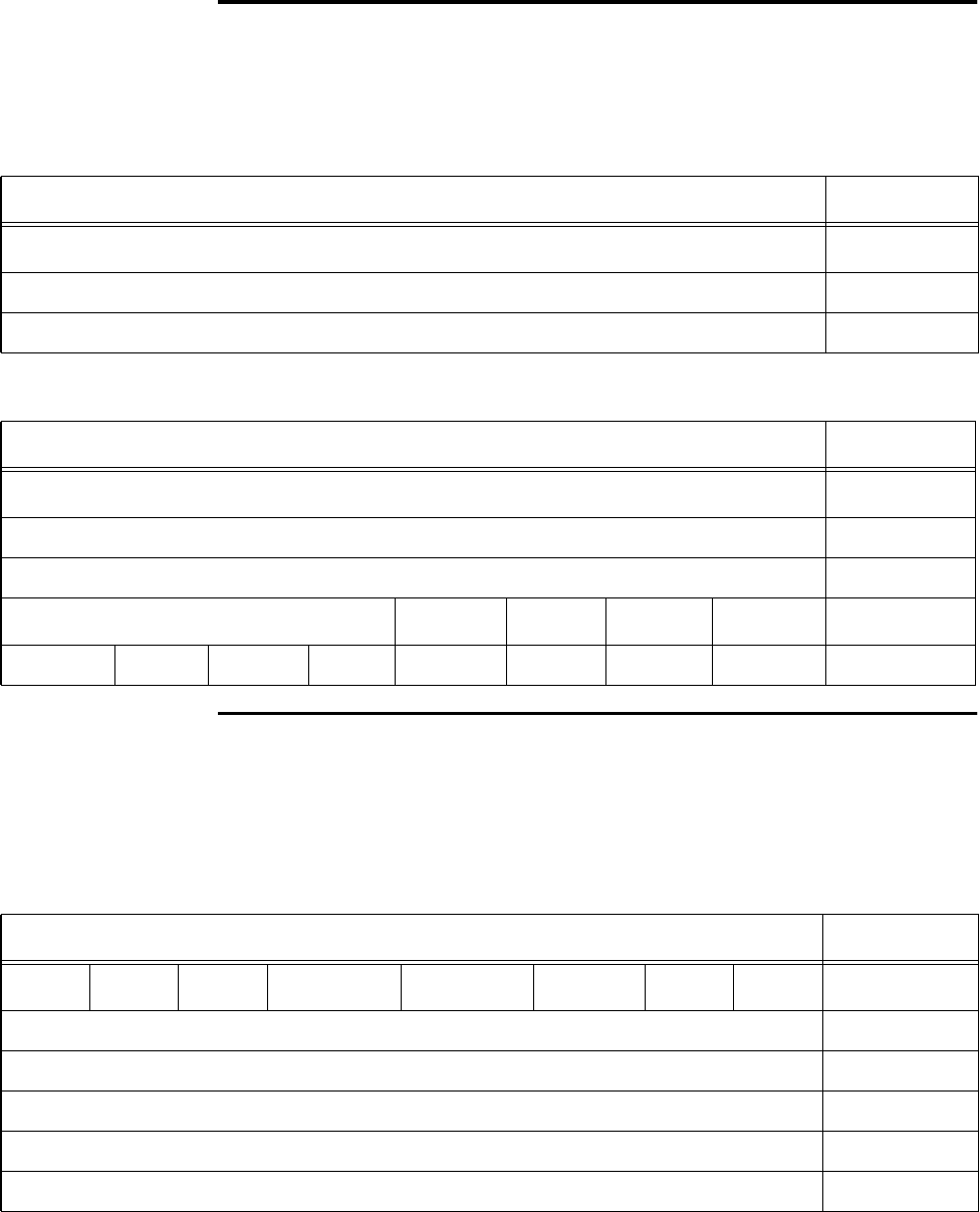
Orion Reader System Guide
6-124 Use or disclosure of Proprietary Information contained on this sheet is subject to the restriction stated on the title page of this document.
Get Protocol
This command retrieves the Orion Reader specified protocols. Table 6-208 and Table
6-209 list the command and response data.
Set Seen Count
This command records the number of times the Orion Reader reads a tag after the sys-
tem has finished the complete transaction. Table 6-210 and Table 6-211 list the com-
mand and response data.
Table 6-208 Get Protocol Command (0004H)
Set Protocol Command Data Data Payload
Bits 7–0
Get Protocol Command (MSB) 00H
Get Protocol Command (LSB) 04H
Table 6-209 Get Protocol Response
Set Protocol Response Data Data Payload
Bits 7–0
Get Protocol Command (MSB) 00H
Get Protocol Command (LSB) 04H
Reserved 6C (EPC) CVISN IAG Rsvd 0XH
IAG Read Title 21 Reserved XXH
Table 6-210 Set Seen Count Command (0066H)
Set Seen Count Command Data Data Payload
Bit 7 Bit 6 Bit 5 Bit 4 Bit 3 Bit 2 Bit 1 Bit 0
Set Seen Count Command (MSB) 00H
Set Seen Count Command (LSB) 66H
Protocol 0XH
Seen Frame Counter in Sync Frames (MSB) XXH
Seen Frame Counter in Sync Frames (LSB) XXH
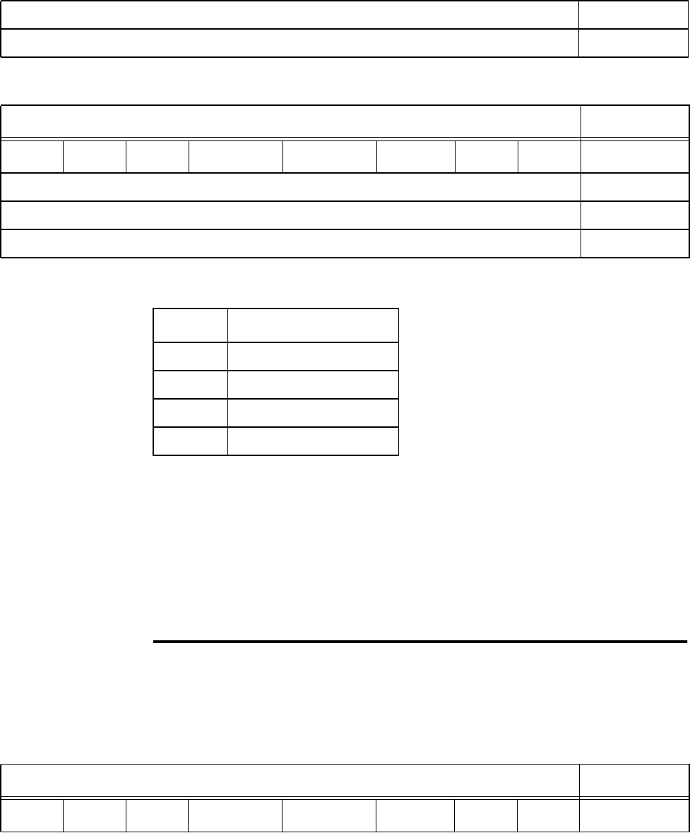
Configuring and Operating the Orion Reader Using TCP Commands
Use or disclosure of Proprietary Information contained on this sheet is subject to the restriction stated on the title page of this document. 6-125
Protocol — This field specifies the protocol for the counters.
Seen Frame Counter — Length of Seen Frame Counter in number of frames. Counts
the specified number of Sync frames, then reports the Seen Count to the host. This
field is used to vary the time interval between seen count messages.
Uniqueness Counter — Length of Uniqueness Counter in number of frames. This
field removes a tag from the seen table when that tag has not been read for the speci-
fied number of Sync frames.
Get Seen Count
This command gets the seen count. Table 6-212 and Table 6-213 list the command
and response data.
Uniqueness Counter in Sync Frames (MSB) XXH
Uniqueness Counter in Sync Frames (LSB) XXH
Table 6-211 Set Seen Count Response
Set Seen Count Response Data Data Payload
Bit 7 Bit 6 Bit 5 Bit 4 Bit 3 Bit 2 Bit 1 Bit 0
Set Seen Count Command (MSB) 00H
Set Seen Count Command (LSB) 66H
Protocol 0XH
Table 6-210 Set Seen Count Command (0066H)
Protocol Definition
2IAG
3 CVISN
4 Title 21
8 ISO 18000-6C (EPC)
Table 6-212 Get Seen Count Command (0067H)
Get Seen Count Command Data Data Payload
Bit 7 Bit 6 Bit 5 Bit 4 Bit 3 Bit 2 Bit 1 Bit 0
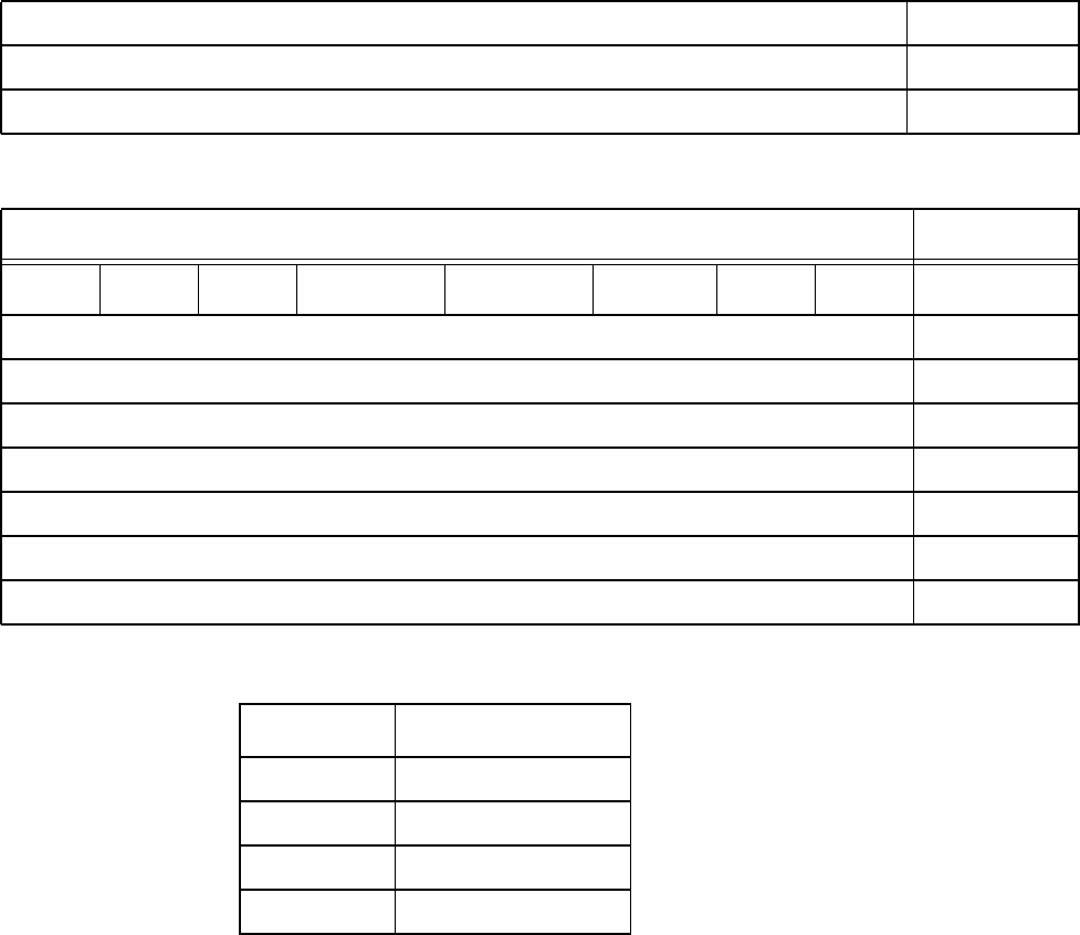
Orion Reader System Guide
6-126 Use or disclosure of Proprietary Information contained on this sheet is subject to the restriction stated on the title page of this document.
Protocol — This field specifies the protocol for the counters.
Seen Frame Counter — Length of Seen Frame Counter in number of frames. Counts
the specified number of Sync frames, then reports the Seen Count to the host. This
field is used to vary the time interval between seen count messages.
Uniqueness Counter — Length of Uniqueness Counter in number of frames. This
field removes a tag from the seen table when that tag has not been read for the speci-
fied number of Sync frames.
Get Seen Count Command (MSB) 00H
Get Seen Count Command (LSB) 67H
Protocol 0XH
Table 6-213 Get Seen Count Response
Get Seen Count Response Data Data Payload
Bit 7 Bit 6 Bit 5 Bit 4 Bit 3 Bit 2 Bit 1 Bit 0
Get Seen Count Command (MSB) 00H
Get Seen Count Command (LSB) 67H
Protocol 0XH
Seen Frame Counter in Sync Frames (MSB) XXH
Seen Frame Counter in Sync Frames (LSB) XXH
Uniqueness Counter in Sync Frames (MSB) XXH
Uniqueness Counter in Sync Frames (LSB) XXH
Table 6-212 Get Seen Count Command (0067H)
Protocol Definition
2IAG
3 CVISN
4 Title 21
8 ISO 18000-6C (EPC)

Configuring and Operating the Orion Reader Using TCP Commands
Use or disclosure of Proprietary Information contained on this sheet is subject to the restriction stated on the title page of this document. 6-127
Diagnostic Command Group Commands (0200H)
Table 6-214 lists the Diagnostic Command Group commands that are used in the
Orion multiprotocol reader.
Diagnostic Command Group Responses
Table 6-215 lists the responses and codes for the Diagnostic Command Group.
Table 6-214 Diagnostic Command Group Commands
Diagnostic Command Command
Code
Get Diagnostic Status 0001H
Get Diagnostic Interface Status 0002H
Get Error Log 0003H
Get Number of Error Logs 0004H
Clear Error Logs 0005H
Reserved 0006H
Reserved 0007H
Table 6-215 Diagnostic Command Group Responses
Diagnostic Response Response
Code
Synchronous OK Status Responses 88XXH
Reserved 8800H
Reserved 8801H
Asynchronous OK Status Responses 48XXH
Command Complete 4800H
Command In Progress 4801H
Unsolicited OK Status Responses 28XXH
Diagnostic Status Change OK Report 2810H

Orion Reader System Guide
6-128 Use or disclosure of Proprietary Information contained on this sheet is subject to the restriction stated on the title page of this document.
Reserved 84XXH
Reserved 44XXH
Reserved 24XXH
Reserved 2410H
Synchronous Error Status Responses 82XXH
Message Length Error 8200H
Message Sequence Error 8201H
Reserved 8202H
Command Group Error 8203H
Reserved 8204H
Reserved 8205H
Reserved 8206H
Reserved 8207H
Reserved 8208H
Data Acknowledge Response Error 8209H
Reserved 820AH
Asynchronous Error Status Responses 42XXH
Message Length Error 4200H
Command Sequence Error 4201H
Reserved 4202H
Command Group Error 4203H
Command Time-out Error 4204H
Table 6-215 Diagnostic Command Group Responses
Diagnostic Response Response
Code

Configuring and Operating the Orion Reader Using TCP Commands
Use or disclosure of Proprietary Information contained on this sheet is subject to the restriction stated on the title page of this document. 6-129
Diagnostic Command Group Response Data
Asynchronous OK Status Responses
The following diagnostic command group asynchronous OK status responses use the
specified data payload.
Reserved 4205H
Command Failed Error 4206H
System Command Error 4207H
Sub-Command Error 4208H
Reserved 4209H
Invalid Control Word Error 420AH
Unsolicited Error Status Responses 22XXH
Diagnostic Status Change Error Report 2210H
Synchronous Control Status Responses 81XXH
Data Acknowledge (Ack), data valid 8100H
Data Negative Acknowledge (Nack), data invalid 8101H
Reserved 8102H
Reserved 8104H
Asynchronous Control Status Responses 41XXH
Unsolicited Control Status Responses 21XXH
Table 6-215 Diagnostic Command Group Responses
Diagnostic Response Response
Code

Orion Reader System Guide
6-130 Use or disclosure of Proprietary Information contained on this sheet is subject to the restriction stated on the title page of this document.
Command Complete (4800H)
Command In Progress (4801H)
Command In Progress Response Data Data
Payload
Diagnostic Command Group Command (sub-command) XXXXH
Command In Progress Response Data Data
Payload
Diagnostic Command Group Command (sub-command) XXXXH

Configuring and Operating the Orion Reader Using TCP Commands
Use or disclosure of Proprietary Information contained on this sheet is subject to the restriction stated on the title page of this document. 6-131
Synchronous Error Status Responses
The following diagnostic command group synchronous error status responses use the
specified data payload.
Message Length Error Response Data (8200H)
Message Sequence Error Response Data (8201H)
Command Group Error Response Data (8203H)
Data Acknowledge Response Error Response Data (8209H)
Asynchronous Error Status Responses
The following diagnostic command group asynchronous error status responses use the
specified data payload.
Message Length Error Response Data Data
Payload
Expected Message Length XXXXH
Received Message Length XXXXH
Message Sequence Error Response Data Data
Payload
Expected Message Sequence Number XXH
Received Message Sequence Number XXH
Command Group Error Response Data Data
Payload
Invalid Command Group XXXXH
Data Acknowledge Response Error Response Data Data
Payload
Invalid Data Acknowledge Response XXXXH

Orion Reader System Guide
6-132 Use or disclosure of Proprietary Information contained on this sheet is subject to the restriction stated on the title page of this document.
Message Length Error Response Data (4200H)
Command Sequence Error Response Data (4201H)
Command Group Error (4203H)
Command Time-out Error (4204H)
Command Failed Error (4206H)
System Command Error (4207H)
Message Length Error Response Data Data
Payload
Expected Message Length XXXXH
Received Message Length XXXXH
Command Sequence Error Response Data Data
Payload
Expected Command Sequence Number XXH
Received Command Sequence Number XXH
Command Group Error Response Data Data
Payload
Invalid Command Group XXXXH
Command Time-out Error Response Data Data
Payload
N/A
Command Failed Error Response Data Data
Payload
Diagnostic Command Group Command (sub-command) XXXXH
System Command Error Response Data Data
Payload
N/A
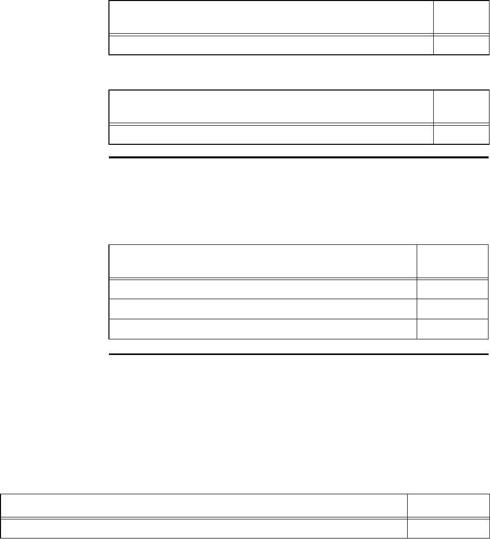
Configuring and Operating the Orion Reader Using TCP Commands
Use or disclosure of Proprietary Information contained on this sheet is subject to the restriction stated on the title page of this document. 6-133
Sub-Command Error (4208H)
Invalid Control Word Error (420AH)
Unsolicited Diagnostic Status Reports
Diagnostics supports the generation of the following unsolicited status message
reports as defined by the response code (Table 6-216).
Get Diagnostic Status
This command gets the current diagnostic status of the Orion Reader as defined by the
Diagnostic Status Bit definitions that include FRAM test status, FPGA1/FPGA2 test
status, digital board power supply status, RF transceiver status, GPS status, Sync sta-
tus, communication link status, reset count, CPU firmware fault status, buffered tag
transaction entries status, and error log entries status. Table 6-217 and Table 6-218 list
the command and response data.
Sub-Command Error Response Data Data
Payload
Sub-command XXXXH
Invalid Control Word Error Response Data Data
Payload
N/A
Table 6-216 Diagnostic Unsolicited Status Reports
Diagnostic Unsolicited Status Reports Response
Code
Diagnostic Status Change OK Report 2810H
Reserved 2410H
Diagnostic Status Change Error Report 2210H
Table 6-217 Get Diagnostic Status Command (0001H)
Get Diagnostic Status Command Data Data Payload
Get Diagnostic Status Command 0001H

Orion Reader System Guide
6-134 Use or disclosure of Proprietary Information contained on this sheet is subject to the restriction stated on the title page of this document.
Table 6-218 Get Diagnostic Status Response
Get Diagnostic Status Response Data Data Payload
Get Diagnostic Status Command 0001H
Diagnostic Status (MSB) XXH
Diagnostic Status XXH
Diagnostic Status XXH
Diagnostic Status XXH
Diagnostic Status XXH
Diagnostic Status XXH
Diagnostic Status XXH
Diagnostic Status (LSB) XXH

Configuring and Operating the Orion Reader Using TCP Commands
Use or disclosure of Proprietary Information contained on this sheet is subject to the restriction stated on the title page of this document. 6-135
Diagnostic Status Bit Definitions
Table 6-219 lists the bit definitions for the diagnostic status response.
Table 6-219 Diagnostic Status Bit Definitions
Bit Diagnostic Status Bit Definition
63 Reserved
62 Reserved
61 Reserved
60 Reserved
59 Reserved
58 FRAM test status, where 0 = OK, 1 = error
57 FRAM data storage test status, where 0 = OK, 1 = error
56 Reserved
55 Reserved
54 Reserved
53 Reserved
52 Reserved
51 Reserved
50 FPGA1 test status, where 0 = OK, 1 = error
49 FPGA2 test status, where 0 = OK, 1 = error
48 Power supply status, where 0 = OK, 1 = error
47 Digital board overvoltage error, where0=noerror, 1 = error
46 Digital board undervoltage error, where0=noerror, 1 = error
45 Reserved
44 Reserved
43 RF transceiver ADC above maximum error, where0=noerror, 1 = error
42 RF transceiver ADC below minimum error, where0=noerror, 1 = error
41 RF transceiver ATTN DAC1 above maximum error, where0=noerror, 1 = error
40 RF transceiver ATTN DAC1 below minimum error, where0=noerror, 1 = error
39 RF transceiver ATTN DAC2 above maximum error, where0=noerror, 1 = error
38 RF transceiver ATTN DAC2 below minimum error, where0=noerror, 1 = error

Orion Reader System Guide
6-136 Use or disclosure of Proprietary Information contained on this sheet is subject to the restriction stated on the title page of this document.
37 RF transceiver DOM DAC above maximum error, where0=noerror, 1 = error
36 RF transceiver DOM DAC below minimum error, where0=noerror, 1 = error
35 RF transceiver source1 PLL unlocked error, where0=noerror, 1 = error
34 RF transceiver source2 PLL unlocked error, where0=noerror, 1 = error
33 RF transceiver uncalibrated error, where0=noerror, 1 = error
32 RF transceiver 5VDC overvoltage error, where0=noerror, 1 = error
31 RF transceiver 5VDC undervoltage error, where0=noerror, 1 = error
30-23 Reserved
22 GPS T-RAIM alarm set, where 0 = alarm not set, 1 = alarm set
21 GPS self-test fault, where0=nofault,1=fault
20 GPS power-on fault, where0=nofault,1=fault
19 Sync two masters error, where0=noerror, 1 = error
18 Sync master-slave error, where0=noerror, 1 = error
17 Sync clock error, where0=noerror, 1 = error
16 GPS window error, where0=noerror, 1 = error
15 GPS one-PPS error, where0=noerror, 1 = error
14 GPS communication link status, where 0 = link up, 1 = link down
13 Serial communication link status, where 0 = link up, 1 = link down
12 TCP/IP communication link status, where 0 = link up, 1 = link down
11 Serial debug communication link status, where 0 = link up, 1 = link down
10 RF transceiver communication link status, where 0 = link up, 1 = link down
9 Reserved
8 Reserved
7 Reset count (MSB)
6 Reset count
5 Reset count
4 Reset count (LSB)
3 CPU firmware fault, where0=nofault,1=fault
Table 6-219 Diagnostic Status Bit Definitions
Bit Diagnostic Status Bit Definition

Configuring and Operating the Orion Reader Using TCP Commands
Use or disclosure of Proprietary Information contained on this sheet is subject to the restriction stated on the title page of this document. 6-137
2 Reserved
1 Buffered tag transaction entries, where0=noentries, 1 = entries
0 Error log entries, where0=noentries, 1 = entries
Table 6-219 Diagnostic Status Bit Definitions
Bit Diagnostic Status Bit Definition

Orion Reader System Guide
6-138 Use or disclosure of Proprietary Information contained on this sheet is subject to the restriction stated on the title page of this document.
Get Diagnostic Interface Status
This command gets the reader’s current diagnostic interface software status. Table 6-
220 and Table 6-221 list the command and response data.
Get Error Log
This command gets the error log. The error log lists the errors in chronological order.
Table 6-222 and Table 6-223 list the command and response data.
Table 6-220 Get Diagnostic Interface Status Command (0002H)
Get Diagnostic Interface Status Command Data Data Payload
Get Diagnostic Interface Status Command 0002H
Table 6-221 Get Diagnostic Interface Status Response
Get Diagnostic Interface Status Response Data Data Payload
Get Diagnostic Interface Status Command 0002H
Module Number XXXXH
Error Number XXXXH
Table 6-222 Get Error Log Command (0003H)
Get Error Log Command Data Data Payload
Get Error Log Command 0003H
Error Log Number XXXXH
Table 6-223 Get Error Log Response
Get Error Log Response Data Data Payload
Get Error Log Command 0003H
Error log number XXXXH
Module number XXXXH
Error number XXXXH
Time stamp: hours XXH
Time stamp: minutes XXH

Configuring and Operating the Orion Reader Using TCP Commands
Use or disclosure of Proprietary Information contained on this sheet is subject to the restriction stated on the title page of this document. 6-139
Get Number of Error Logs
This command gets the number of error logs. The error log overflow status is returned
as 0 for no overflow or 1 for overflow. Table 6-224 and Table 6-225 list the command
and response data..
Clear Error Logs
This command clears entries from the error log. Table 6-226 and Table 6-227 list the
command and response data
Time stamp: seconds XXH
Time stamp: hundredths of seconds XXH
Time stamp: month XXH
Time stamp: day XXH
Time stamp: year XXH
Table 6-223 Get Error Log Response
Get Error Log Response Data Data Payload
Table 6-224 Get Number Error Logs Command (0004H)
Get Number of Error Logs Command Data Data Payload
Get Number of Error Logs Command 0004H
Table 6-225 Get Number Error Logs Response
Get Number of Error Logs Response Data Data Payload
Get Number of Error Logs Command 0004H
Number of error logs XXXXH
Error log overflow status, where0=nooverflow,1=overflow XXH
Table 6-226 Clear Error Logs Command (0005H)
Clear Error Logs Command Data Data Payload
Clear Error Logs Command 0005H
Clear Error Logs Control Word A5A5H

Orion Reader System Guide
6-140 Use or disclosure of Proprietary Information contained on this sheet is subject to the restriction stated on the title page of this document.
Table 6-227 Clear Error Logs Response
Clear Error Logs Response Data Data Payload
Clear Error Logs Command 0005H

7
Tag Responses

Tag Responses
Use or disclosure of Proprietary Information contained on this sheet is subject to the restriction stated on the title page of this document. 7-3
Chapter 7
Tag Responses
This chapter provides tag responses for transmission control protocol
(TCP).
TCP Tag Responses
In general, the tag response is transmitted as the record type code and the tag response
data. Response lengths vary depending on the tag response record type. The tag
response record type communicates to the host the tag response type that the reader
processed.
TCP Tag Response Field Definitions
Tag command processing allows the host-Orion® Reader interface to be more under-
standable and maintainable. All of the interfaces closely parallel the Orion Reader-to-
tag interface. Tag processing responses are listed in Table 7-1.
Specific TCP Tag Responses
This section describes the various tag responses to requests.
Tag Data and CRC are used for parsing and format purposes only. The record types
shown contain valid data.
Table 7-1 Tag Transaction Record Types
Record Type Code Corresponding Tag Response
3024H Title 21 Read Response
3043H Seen Frame Counter Report
5014H CVISN Read Response
5026H IAG Read Response
5027H IAG Cross-Lane Read Response
7000H EPC Read Response
7010H EPC + TID Read Response (Mode 89 Only)
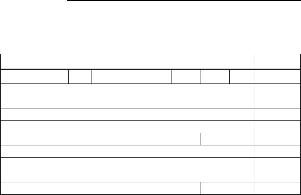
Orion Reader System Guide
7-4 Use or disclosure of Proprietary Information contained on this sheet is subject to the restriction stated on the title page of this document.
Title 21 Read Response
The Title 21 Read Response is as follows: 3024<Data><CRC>. Table 7-2 lists the
response data.
Note: A Title 21 response consists of a 0001 record type; however, there is a response
code conflict with the Set Mode Command response (0001) in TCP. The Orion Reader
addresses this conflict by replacing the 0001 Title 21 response code with a 3024
response code.
Record Type
This field identifies the message as a Title 21 Read Response message. This field con-
tains the following value: 3024H - Title 21 Read_Response.
Tag Type
This four-bit field is used to uniquely differentiate the State of California tags/tran-
sponders from those originating in other state agencies. Currently, the tag type value
defaults to 0 (California). Values of 1 to 15 are unassigned at this time.
Internal Tag ID
This field contains the Title 21 ID for the responding tag.
CRC
This field contains the standard message CRC. The CRC is calculated for all data
beginning with the transaction record type code and includes everything occurring
previous to the error detection code field.
Table 7-2 Title 21 Read Response (3024H)
Title 21 Read Response Data Data Payload
Field Bit 7 Bit 6 Bit 5 Bit 4 Bit 3 Bit 2 Bit 1 Bit 0
Record Record Type (MSB) 30H
Record Record Type (LSB) 24H
Data (MSB) Tag Type (4 bits) Facility Code (18 bits) XXH
Data Facility Code
Data Facility Code Internal Tag ID XXH
Data (LSB) Internal Tag ID (10 bits) XXH
CRC CRC XXH
CRC CRC XXH
Antenna Antenna Number 0XH
Tag Responses
Use or disclosure of Proprietary Information contained on this sheet is subject to the restriction stated on the title page of this document. 7-5
Facility Code
This field identifies the agency issuing the tags.
Title 21 Read Response Example:
Title 21 Tag Read Response
30240FCE8E7DD4E400 0 258979 637
where
3024 Title 21 tag response code
0FCE8E7D 32-bit tag ID
D4E4 CRC
00 Antenna number (single channel)
0 258979 637 Parsed Title 21 32-bit tag ID (decimal)
where
0Tag type
258979 Facility code
637 Internal tag ID

Orion Reader System Guide
7-6 Use or disclosure of Proprietary Information contained on this sheet is subject to the restriction stated on the title page of this document.
CVISN Seen Frame Counter Report
This message reports the seen count value when the seen frame counter times out if
the seen count is greater than zero for a tag listed in the table. The seen frame counter
report is populated with a minimum of one tag and a maximum of eight tags. The
report is always the same size. Active tags are packed in ascending order; the first
active tag and associated seen count read from the FPGA firmware seen count table is
placed in the report at tag ID 0. The first seen count field in the report (MSB and LSB)
that is set to zero indicates the end of the active tag list in the report (Table 7-3).
Table 7-3 CVISN Seen Frame Counter Report (5012H)
CVISN Seen Frame Counter Report Data Data Payload
Bits 7–0
Record Type (MSB) 50H
Record Type (LSB) 12H
Protocol 0XH
Seen Count (MSB) XXH
Seen Count (LSB) XXH
Tag ID 0 (32 bits) XXXXXXXXH
Seen Count (MSB) XXH
Seen Count (LSB) XXH
Tag ID 1 (32 bits) XXXXXXXXH
Seen Count (MSB) XXH
Seen Count (LSB) XXH
Tag ID 2 (32 bits) XXXXXXXXH
Seen Count (MSB) XXH
Seen Count (LSB) XXH
Tag ID 2 (32 bits) XXXXXXXXH
Seen Count (MSB) XXH
Seen Count (LSB) XXH
Tag ID 3 (32 bits) XXXXXXXXH
Seen Count (MSB) XXH
Seen Count (LSB) XXH

Tag Responses
Use or disclosure of Proprietary Information contained on this sheet is subject to the restriction stated on the title page of this document. 7-7
Tag ID 4 (32 bits) XXXXXXXXH
Seen Count (MSB) XXH
Seen Count (LSB) XXH
Tag ID 5 (32 bits) XXXXXXXXH
Seen Count (MSB) XXH
Seen Count (LSB) XXH
Tag ID 6 (32 bits) XXXXXXXXH
Seen Count (MSB) XXH
Seen Count (LSB) XXH
Tag ID 7 (32 bits) XXXXXXXXH
Table 7-3 CVISN Seen Frame Counter Report (5012H)

Orion Reader System Guide
7-8 Use or disclosure of Proprietary Information contained on this sheet is subject to the restriction stated on the title page of this document.
Seen Frame Counter Report
This message is use to report the value of the Seen Count when the Seen Frame
Counter times out and if the Seen Count is greater than zero. The Seen Frame Counter
Response is as follows: 3043<Data><CRC> Table 7-4 lists the response data.
Protocol — This field specifies the protocol for the counters.
CVISN Read Response
The CVISN Read Response format is as follows: 5014<Data><CRC>. Table 7-5 lists
the response data.
Table 7-4 Seen Frame Counter Report (3043H)
Seen Frame Counter Report Data Payload
Field Bits 7–0
Record Record Type (MSB) 30H
Record Record Type (LSB) 43H
Data Protocol 0XH
Data Seen Count (MSB) XXH
Data Seen Count (LSB) XXH
Antenna Antenna 0XH
Protocol Definition
2IAG
3 CVISN
4 Title 21
8 ISO 18000-6C (EPC)
Table 7-5 CVISN Read Response (5014H)
CVISN Read Response Data Data Payload
Field Bits 7–0
Record Record Type (MSB) 50H
Record Record Type (LSB) 14H

Tag Responses
Use or disclosure of Proprietary Information contained on this sheet is subject to the restriction stated on the title page of this document. 7-9
The valid tags are set to 0 for tag not in frame slot and 1 for tag in frame slot. The tran-
sponder message is the high-order nibble and the message type tag is the low-order
nibble. This byte is passed with each tag but currently is not used. The transponder ID
tag is the identifier read from the tag. There may be one to four tags read for a given
response. A read with no transponder ID tags is not forwarded to the host. The reader
also presents a tag’s CRC to the host as part of the response in the CRC field.
IAG Read Response
Data Valid Tag 1 0000H/0001H
Data Valid Tag 2 0000H/0001H
Data Valid Tag 3 0000H/0001H
Data Valid Tag 4 0000H/0001H
Data Transponder Message and Message Type Tag 1 (not used) XXH
Data Transponder ID Tag 1 XXXX.XXXXH
CRC CRC Tag 1 XXXXH
Data Tag Type Indicator (Toll Tag = 01H) XXH
Data Transponder Message and Message Type Tag 2 (not used) XXH
Data Transponder ID Tag 2 XXXX.XXXXH
CRC CRC Tag 2 XXXXH
Data Tag Type Indicator (Toll Tag = 01H) XXH
Data Transponder Message and Message Type Tag 3 (not used) XXH
Data Transponder ID Tag 3 XXXX.XXXXH
CRC CRC Tag 3 XXXXH
Data Tag Type Indicator (Toll Tag = 01H) XXH
Data Transponder Message and Message Type Tag 4 (not used) XXH
Data Transponder ID Tag 4 XXXX.XXXXH
CRC CRC Tag 4 XXXXH
Data Tag Type Indicator (Toll Tag = 01H) XXH
Antenna Antenna Number XXH
Table 7-5 CVISN Read Response (5014H) (continued)

Orion Reader System Guide
7-10 Use or disclosure of Proprietary Information contained on this sheet is subject to the restriction stated on the title page of this document.
The IAG Read Response format is as follows: 5026<Data><CRC>. Table 7-6 lists the
response data.
Table 7-6 IAG Read Response Data Parameters (5026H)
IAG Read Response Data
Payload
Field Bit 7 Bit 6 Bit 5 Bit 4 Bit 3 Bit 2 Bit 1 Bit 0
Record Record Type (MSB) 50H
Record Record Type (LSB) 26H
Read Only Partition
Data Header (3 bits) Tag Type (3 bits) App ID (3 bits) XXH
Data App ID Group ID (7 bits) XXH
Data Agency ID (7 bits) Ser Num XXH
Data Serial Number (24 bits) XXH
Data Serial Number XXH
Data Serial Number V. Class XXH
Data Vehicle Class (11 bits) XXH
Data Vehicle Class Revenue Type (4 bits) C. S. M. L. XXH
Data M. L. Agency Data 1 (3 bits) ISTHA Class (4 bits) XXH
Data Agency Data 2 (24 bits) XXH
Data Agency Data 2 XXH
Data Agency Data 2 XXH
Read/Write Partition
Data Reader ID (12 bits) XXH
Data Reader ID TM Date (9 bits) XXH
Data TM Date TM Time (17 bits) XXH
Data TM Time XXH
Data TM Time Agency ID (7 bits) XXH
Data Agency ID Plaza ID (7) XXH
Data Plaza ID Lane ID (5 bits) XXH
Data Lane ID Data (9 bits) XXH

Tag Responses
Use or disclosure of Proprietary Information contained on this sheet is subject to the restriction stated on the title page of this document. 7-11
IAG Read Response Example
#5026ECC11E01FCB21200010587052DBAAAD1607852D89687D54E03060001AAFB5983
where
Note: Due to overlap of byte boundaries by tag data fields, all further data break-
down will be in binary.
Hex tag data:
MSB ECC11E01FCB21200 010587052DBAAAD1 607852D89687D54E 03060001AAFB5983 LSB
32 bytes tag data*8 bits/byte = 256 bits
32 bytes/8 bytes per line = 4 lines
256 bits/4 lines = 64 bits/line from MSB to LSB
Data Date Time (17 bits) XXH
Data Time XXH
Data Time Vehicle Class (11 bits) XXH
Data Vehicle Class Future (4 bits) XXH
Data Future Agency Data (30 bits) XXH
Data Agency Data XXH
Data Agency Data XXH
Data Agency Data XXH
Data Transaction Number (16 bits) XXH
Data Transaction Number XXH
CRC CRC XXH
CRC CRC XXH
Antenna Antenna
Table 7-6 IAG Read Response Data Parameters (5026H) (continued)
IAG Read Response Data
Payload
Field Bit 7 Bit 6 Bit 5 Bit 4 Bit 3 Bit 2 Bit 1 Bit 0
5026 IAG Read Record Type, 2 bytes in hex
MSB

Orion Reader System Guide
7-12 Use or disclosure of Proprietary Information contained on this sheet is subject to the restriction stated on the title page of this document.
1110110011000001000111100000000111111100101100100001001000000000
0000000100000101100001110000010100101101101110101010101011010001
0110000001111000010100101101100010010110100001111101010101001110
0000001100000110000000000000000110101010111110110101100110000011
Response breakdown is from MSB to LSB, starting with the header field and ending
with the CRC.
Read-Only Partition
Read/Write Partition
Field (# of bits) : Bit Pattern : Decimal
Header (3 bits) : 111 :7
Tag Type (3 bits) : 011 :3
Application ID (3 bits) : 001 :1
Group ID (7 bits) : 1000001 :65
Agency ID (7 bits) : 0001111 :15
Serial Number (24 bits) : 000000001111111001011001 : 65113
Vehicle Class (11 bits) : 00001001000 :72
Revenue Type (4 bits) : 0000 :0
Commission Status (1 bit) : 0:0
Mounting Location (2 bits) : 00 :00
Agency Data 1 (3 bits) : 000 : 000
ISTHA Class (4 bits) : 0001 :1
Agency Data 2 (24 bits) : 000001011000011100000101 : 362245
Field (# of bits) : Bit Pattern : Decimal
Reader ID (12 bits) : 001011011011 : 731
TM Date (9 bits) : 101010101 : 341
TM Time (17 bits) : 01011010001011000 : 46168
Agency ID (7 bits) : 0001111 :15
Plaza ID (7 bits) : 0000101 :5
Lane ID (5 bits) : 00101 :5
Date (9 bits) : 101100010 : 354
LSB
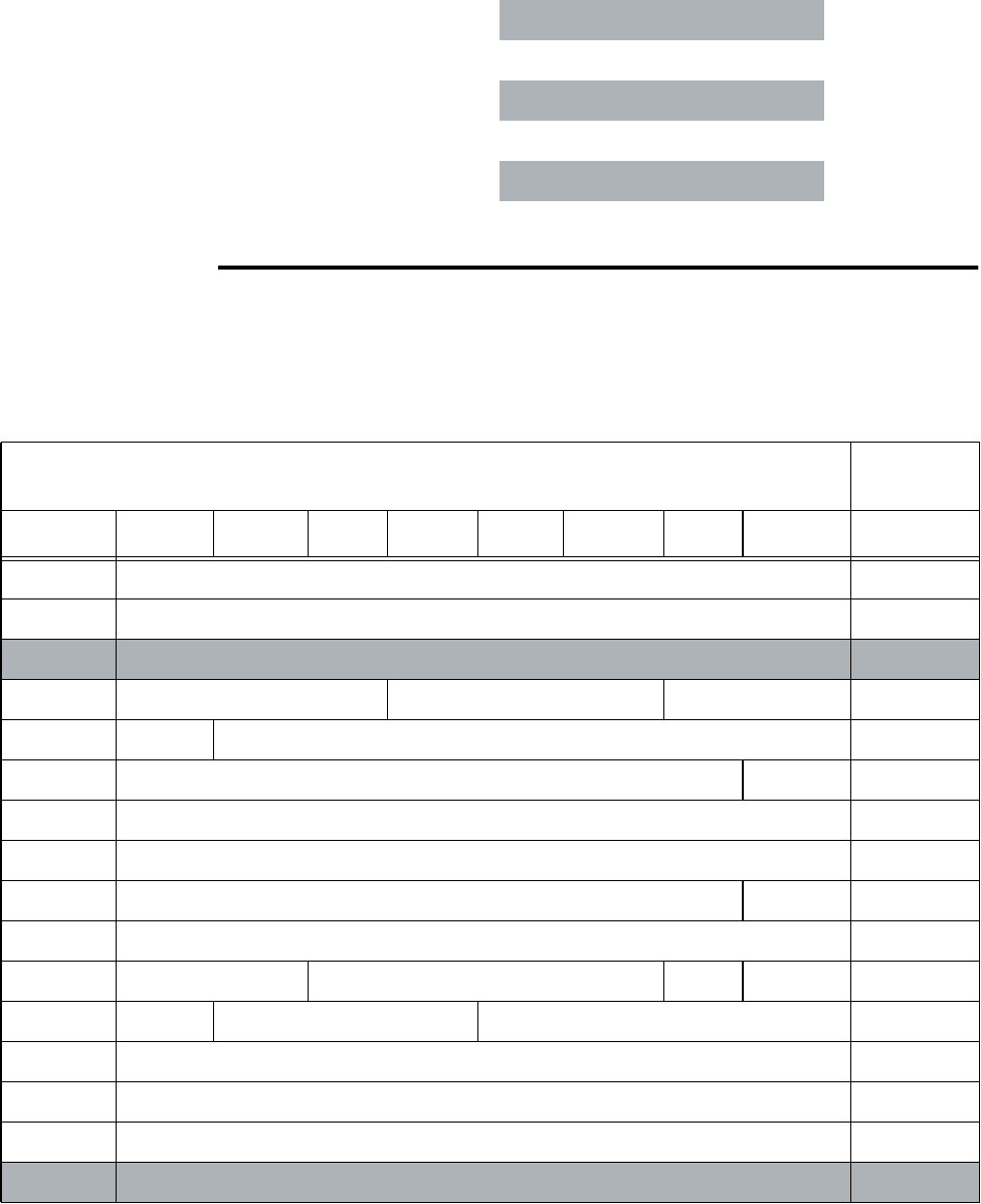
Tag Responses
Use or disclosure of Proprietary Information contained on this sheet is subject to the restriction stated on the title page of this document. 7-13
IAG Cross-Lane Read Response
The IAG Cross-Lane Read Response format is as follows: 5027<Data><CRC>. Table
7-7 lists the response data.
Time (17 bits) : 01011010000111110 : 46142
Vehicle Class (11 bits) : 10101010011 : 1363
Future (4 bits) : 1000 :8
Agency Data (30 bits) :
000011000001100000000000000001
: 50724865
Transaction Number (16 bits)
:1010101011111011 : 43771
CRC (16 bits) : 0101100110000011 : 22915
Table 7-7 IAG Cross-Lane Read Response (5027H)
IAG Cross-Lane Read Response Data
Payload
Field Bit 7 Bit 6 Bit 5 Bit 4 Bit 3 Bit 2 Bit 1 Bit 0
Record Record Type (MSB) 50H
Record Record Type (LSB) 27H
Read-Only Partition
Data Header (3 bits) Tag Type (3 bits) App. ID (3 bits) XXH
Data App ID Group ID (7 bits) XXH
Data Agency ID (7 bits) Ser Num XXH
Data Serial Number (24 bits) XXH
Data Serial Number XXH
Data Serial Number V. Class XXH
Data Vehicle Class (11 bits) XXH
Data Vehicle Class Revenue Type (4 bits) C. S. M. L XXH
Data M. L. Agency Data 1 (3 bits) ISTHA Class (4 bits) XXH
Data Agency Data 2 (24 bits) XXH
Data Agency Data 2 XXH
Data Agency Data 2 XXH
Read/Write Partition

Orion Reader System Guide
7-14 Use or disclosure of Proprietary Information contained on this sheet is subject to the restriction stated on the title page of this document.
IAG Cross-Lane Read Response Example
The IAG Cross-Lane Read Response example is
#5027ECC11E01FCB21200010587052DBAAAD1607852D89687D54E03060001AAFB5983
where
Data Reader ID (12 bits) XXH
Data Reader ID TM Date (9 bits) XXH
Data TM Date TM Time (17 bits) XXH
Data TM Time XXH
Data TM Time Agency ID (7 bits) XXH
Data Agency ID Plaza ID (7) XXH
Data Plaza ID Lane ID (5 bits) XXH
Data Lane ID Date (9 bits) XXH
Data Date Time (17 bits) XXH
Data Time XXH
Data Time Vehicle Class (11 bits) XXH
Data Vehicle Class Future (4 bits) XXH
Data Future Agency Data (30 bits) XXH
Data Agency Data XXH
Data Agency Data XXH
Data Agency Data XXH
Data Transaction Number (16 bits) XXH
Data Transaction Number XXH
CRC CRC XXH
CRC CRC XXH
Antenna Antenna Number
Table 7-7 IAG Cross-Lane Read Response (5027H) (continued)
IAG Cross-Lane Read Response Data
Payload
Field Bit 7 Bit 6 Bit 5 Bit 4 Bit 3 Bit 2 Bit 1 Bit 0
5027 IAG Cross-Lane Read Record Type, 2 bytes in hex

Tag Responses
Use or disclosure of Proprietary Information contained on this sheet is subject to the restriction stated on the title page of this document. 7-15
Note: Due to overlap of byte boundaries by tag data fields, all field breakdowns are
in binary.
Hex tag data:
MSB ECC11E01FCB21200 010587052DBAAAD1 607852D89687D54E 03060001AAFB5983 LSB
32 bytes tag data*8 bits/byte = 256 bits
32 bytes/8 bytes per line = 4 lines
256 bits/4 lines = 64 bits/line from MSB to LSB
1110110011000001000111100000000111111100101100100001001000000000
0000000100000101100001110000010100101101101110101010101011010001
0110000001111000010100101101100010010110100001111101010101001110
0000001100000110000000000000000110101010111110110101100110000011
Response breakdown is from MSB to LSB, starting with the header field and ending
with the CRC.
Read-Only Partition
Field (# of bits) : Bit Pattern : Decimal
Header (3 bits) : 111 :7
Tag Type (3 bits) : 011 :3
Application ID (17 bits) : 001 :1
Group ID (7 bits) : 1000001 :65
Agency ID (7 bits) : 0001111 :15
Serial Number (24 bits) : 000000001111111001011001 : 65113
Vehicle Class (11 bits) : 00001001000 :72
Revenue Type (4 bits) : 0000 :0
Commission Status (11 bits)
:0:0
Mounting Location (2 bits) : 00 :00
Agency Data 1 (3 bits) :
000
: 000
ISTHA Class (4 bits)
:0001 :1
Agency Data 2 (24 bits)
:000001011000011100000101 : 362245
MSB
LSB

Orion Reader System Guide
7-16 Use or disclosure of Proprietary Information contained on this sheet is subject to the restriction stated on the title page of this document.
Read/Write Partition
Field (# of bits) : Bit Pattern : Decimal
Reader ID (12 bits) : 001011011011 : 731
TM Date (9 bits) : 101010101 : 341
TM Time (17 bits) : 01011010001011000 : 46168
Agency ID (7 bits) : 0001111 :15
Plaza ID (7 bits) : 0000101 :5
Lane ID (5 bits) : 00101 :5
Date (9 bits) : 101100010 : 354
Time (17 bits) : 01011010000111110 : 46142
Vehicle Class (11 bits)
:10101010011 : 1363
Future (4 bits) : 1000 :8
Agency Data (30 bits) :
000011000001100000000000000001
: 50724865
Transaction Number (16 bits)
:1010101011111011 : 43771
CRC (16 bits)
:0101100110000011 : 22915

8
Configuring the Lane

Configuring the Lane
Use or disclosure of Proprietary Information contained on this sheet is subject to the restriction stated on the title page of this document. 8-3
Chapter 8
Configuring the Lane
This chapter provides information on the importance of lane tuning for
optimum automatic vehicle identification (AVI) system performance. This
chapter also describes the Orion® Reader functions and features that
can assist you in tuning an AVI lane.
Why You Need to Configure a Lane
Lane configuration optimizes the radio frequency (RF) characteristics and signal tim-
ing of an AVI-equipped toll lane to maximize the performance prescribed by the lane’s
traffic requirements. Typically, consideration of these factors is necessary for each
individual lane, although in some installations it may be possible to identify broader
solutions, then apply these solutions to certain classes of lanes having similar charac-
teristics, followed by additional fine adjustment on an individual lane-by-lane basis.
This process is necessitated by the radio link, which is subject to varying factors such
as:
•Lane type
•Geometry of fixed objects near the capture zone
•Interference from external sources
•Adjacent lane interference
•Natural non-homogeneity of RF field strength within the ideal capture zone
•Varying tag environments
These factors may vary within an installation and from lane to lane within the same
plaza.The tag protocol types used at an installation play a significant role in configur-
ing the lanes for operation. Knowing the appropriate factors and available tools is nec-
essary for the set-up and troubleshooting of AVI lanes.
Marking the Read Zone
The area where the Orion Reader reads tags at the current RF range is called the read
zone. The antenna pattern, or read zone, of the Orion Reader would look roughly like
a pear-shaped balloon if you were able to see it. When installing the toll antenna, you
should first mark the unit’s read zone using the RF range set at the factory-default
maximum.
If two toll antennas are installed near each other, Star Systems recommends that you

Orion Reader System Guide
8-4 Use or disclosure of Proprietary Information contained on this sheet is subject to the restriction stated on the title page of this document.
fine-tune each reader for the ideal read zone before connecting it permanently to sense
input/sense output and communications cables.
Required Supplies
You need the following supplies to mark the read zone:
•Test tags, supplied by the Star Systems dealer or distributor
•Audible circuit tester and 9V DC battery for circuit tester power as described in
the section
•Piece of chalk or roll of tape
•Plastic or wooden yardstick for tags
•Vinyl electrical tape or hook-and-loop material
Guidelines
Note: Using test tags that are not mounted to vehicles give a general idea of the read
pattern, but the pattern will vary somewhat when actual vehicles with tags are tested.
Final adjustments must be made with tags properly mounted on a variety of vehicles.
To mark the read zone
1. Turn on continuous RF power using the #6411 command.
2. Secure the test tag to the end of the yardstick using electrical tape or hook-and-
loop material. Be sure the tag polarization (horizontal or vertical alignment)
matches that of the toll antenna.
3. Stand directly in front of and about 5 feet (1.5 m) away from the overhead toll
antenna. Hold the stick so that the tag is positioned at a height and angle
consistent with a tag installed on a vehicle. The audible tester sounds upon tag
read. If the tester does not sound, try a different tag. If the tester still does not
sound, verify that the tester is working correctly and retest the tag.
Note: If you hold the test tag in your hand, your hand absorbs the RF signal and
the test results are not accurate.
4. Mark the spot with chalk or tape.
5. Move to the left until the sound stops and mark the ground with chalk or tape at
the location of the tag when the sound stopped.
6. Return to the center and then move to the right until the sound stops and mark the
ground with chalk or tape at the location of the tag when the sound stopped.
7. Return to the center and step backward 2 feet (0.6 m) and repeat steps 5 through 7.
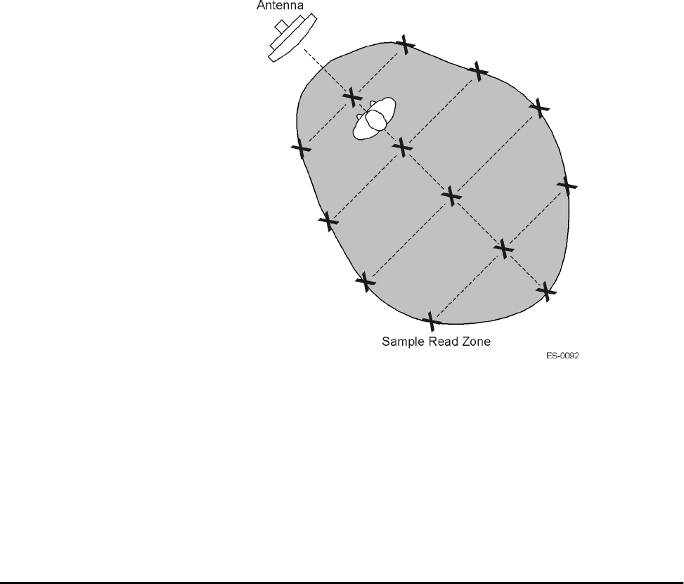
Configuring the Lane
Use or disclosure of Proprietary Information contained on this sheet is subject to the restriction stated on the title page of this document. 8-5
8. Continue moving the tag in this manner, placing marks on the ground to identify
the boundary of the read zone each time the sound stops. Continue moving the
tag to various locations until the read zone is fully marked.
9. You can now connect the outer marks to draw the outer boundary of the read
zone.
Figure 8-1 is a view of a sample read zone within a controlled lane. The outer X
marks show the outside edges of the read zone.
Figure 8-1 Sample Read Zone Marking Pattern
10. Standing at the farthest point of the pattern, walk toward the toll antenna and
listen for a continuous sound from the audible tester. If the sound is not
continuous, it could indicate a weak or patchy RF pattern.
Use the appropriate TCP command (Set RF Attenuation (0051H) or Set Data
Detect (0053H) or both) to adjust the footprint for the installation’s tag protocols.
To decrease the size of the footprint, increase the attenuation, which lowers the
transmit RF power.
Lane Configuration Examples
This section presents starting values for lane configuration parameters that can be
used for various protocol combinations. The tables do not represent all of the possible
protocol combinations available with the Orion Reader, but they provide a framework
for developing installation-specific configuration parameters.

Orion Reader System Guide
8-6 Use or disclosure of Proprietary Information contained on this sheet is subject to the restriction stated on the title page of this document.
Lane Configuration Parameters for Title 21 Protocols
To configure the reader for initial use reading Title 21 protocols, set the recommended
starting values for the parameters listed in Table 8-1.
Table 8-1 Initial Configuration Parameters for Title 21 Protocols
Parameter Recommended Starting Value
Protocol Selection Title 21
Enable Sequence Title 21 Ack or Nack Antenna Set
cTag ID 8-byte tag request ID; however, it is not used in Mode 88 so value should
be set to 0000000000000000H
cCommand Control Always set to 00H for GSE
cPage Data Contains 8 bytes of configurable comparison data. Set to 0 by default
cAntenna Set antenna with values between 0 to 0FH. Set to 0 by default
cAddress Tag memory address for byte mask. Tag memory address varies, so values
for this field may vary
cMask Set mask to desired bit, range = 0–FF
cStart Address Set to 00H
cCommand Depth Set to 00H
Reset Reset reader for changes to take effect
Downlink Frequency Set downlink frequency to 916.00 dB
Uplink Frequency Set uplink frequency to 903.00 dB
Title 21 Downlink Attenuation Set Attenuation so that the line loss and attenuation value = 10 dB
Title 21 Uplink Attenuation Set Attenuation so that the line loss and attenuation value=0dB
Retry Count Recommend setting of 5 for all required retry counts
Title 21 Data Detect Set to 0 dB
Title 21 Seen Count Set to 10 (every 140 ms) for both tag types
Title 21 Uniqueness Count Set to 1000 every 140 seconds for both tag types
Line Loss Set the RF cable loss (line loss from reader to antenna) to the nearest dB
value or 0, 1, 2, or 3

9
System Diagnostics and
Preventive Maintenance
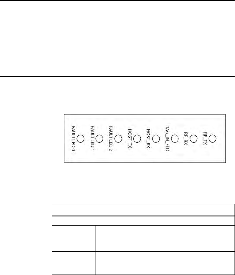
System Diagnostics and Preventive Maintenance
Use or disclosure of Proprietary Information contained on this sheet is subject to the restriction stated on the title page of this document. 9-3
Chapter 9
System Diagnostics and
Preventive Maintenance
This chapter provides information on diagnosing problems with the
Orion® Reader components and schedule and instructions for
preventive maintenance.
Error Indicators
The Orion Reader has light-emitting diodes (LED) that display operational functions
and error conditions. Figure 9-1 shows the LED locations.
Note: The NEMA box must be open in order to view the Operational LEDs.
Figure 9-1 Operational LEDs
Table 9-1 describes the LED indications.
Table 9-1 Operational LED Indicator Descriptions
Operational LED Description
Three fault indication LEDs
Fault
LED 0 Fault
LED 1 Fault
LED 2 Failure Mode
●●●Microprocessor resetting
●●❍Power supply failure
●❍●Transceiver failure
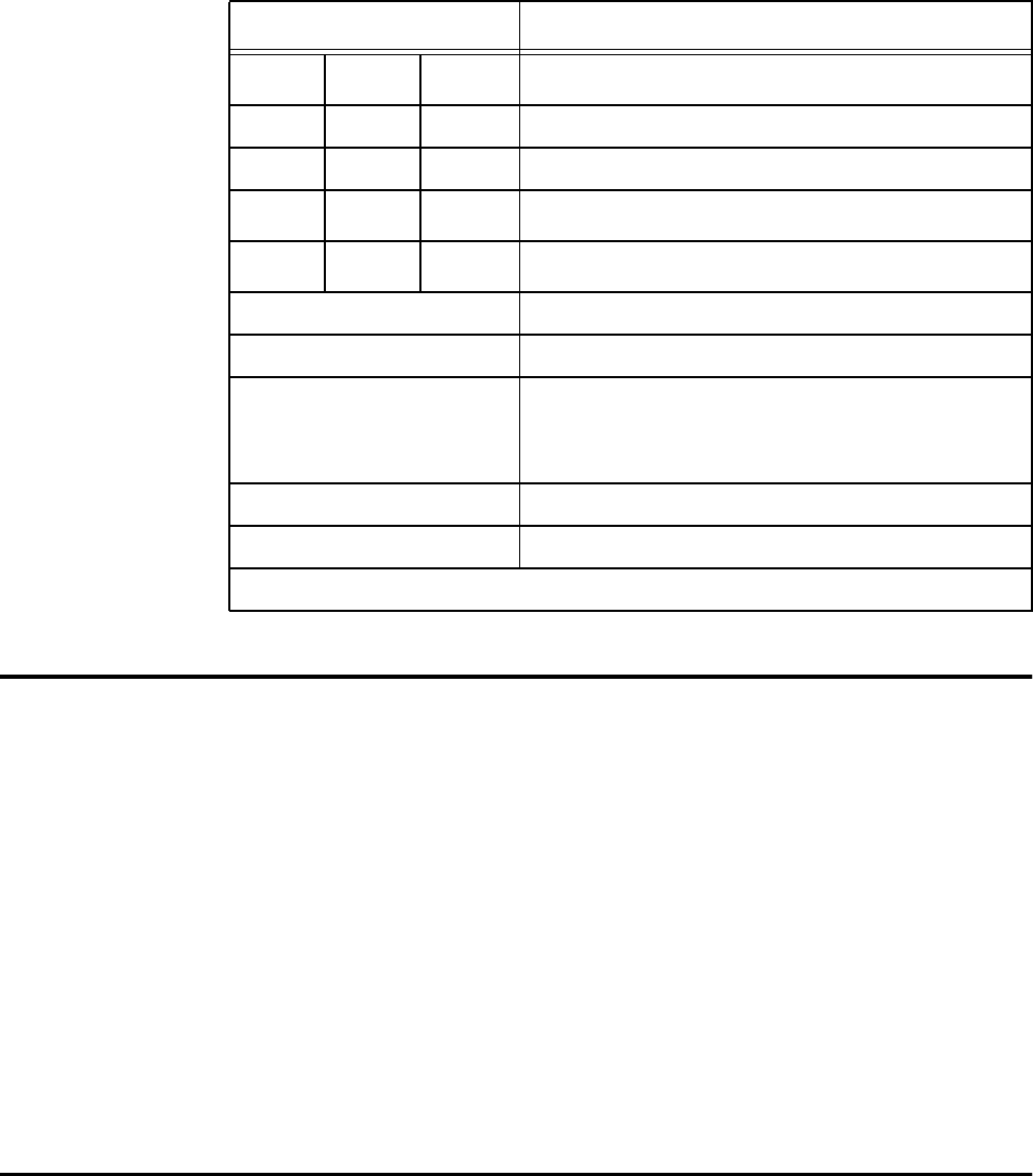
Orion Reader System Guide
9-4 Use or disclosure of Proprietary Information contained on this sheet is subject to the restriction stated on the title page of this document.
Troubleshooting Guidelines
The Orion Reader is very reliable, so any service-related problems will most likely be
due to external causes, such as damage to components. Visually inspect each system
component and replace or repair components as needed.
To perform a visual inspection
1. Make sure all component connectors are secure.
2. Make sure that the antenna is connected to the Orion Reader.
3. Make sure the Orion Reader is powered up by checking the Orion Reader Power
LEDs. The NEMA Box must be open.
4. Make sure the Orion Reader is communicating with the lane controller/host
system by checking operational/fault LEDs.
5. Review diagnostic commands and responses by accessing diagnostic port
(COM2). The NEMA Box must be open.
Communicating Via Diagnostic Port (COM2)
You can check the Orion Reader diagnostics by connecting a personal computer (PC)
●❍❍
Sync/GPS failure
❍●●No communication with lane controller/host system
❍●❍Other failure
❍❍●Data in buffer
❍❍❍
No failure
HOST_TX Orion Reader communicating with host
HOST_RX Host communicating with Orion Reader
TAG_IN_FLD Orion Reader is transacting with tag. LED lit when
Orion Reader receives correctly decoded tag
message including correct CRC for message. The
LED is lit for 250 ms following a tag transaction.
RF_RX RF uplink signal on
RF_TX RF downlink signal on
Note All FAULT LEDs light red.
Table 9-1 Operational LED Indicator Descriptions (continued)
Operational LED Description
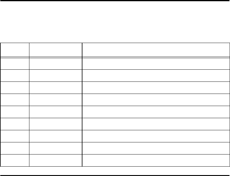
System Diagnostics and Preventive Maintenance
Use or disclosure of Proprietary Information contained on this sheet is subject to the restriction stated on the title page of this document. 9-5
to the Orion Reader COM2 port using a serial null-modem cable. This cable crosses
over the transmit and receive pins, which allows you to communicate with the Orion
Reader. The COM2 port is located inside the NEMA box.
Once you have connected the PC to the Orion Reader, you need to configure the ter-
minal emulation software.
Diagnostic COM2 Port Pin Assignments
This connector is a DB9 subminiature plug.
Starting the Terminal Emulation Software
You can use a PC and any terminal emulation software to enter the host commands to
retrieve diagnostic information. The following procedures show examples using
Hyper Terminal™, an application included with Microsoft Windows. Most terminal
emulation applications have a similar sequence for launching.
Note: In this hyperterminal selection, COM1 refers to the PC communications port.
To start the terminal emulation software
1. At the command prompt, type your terminal emulation start command, or if using
Windows Hyper Terminal, select: Programs>Accessories>Hyperterm
and press ENTER.
The application displays the Connection Description dialog box as shown in
Figure 9-2.
Table 9-2 Diagnostic Communications Connector Parameters
Pin Signal Description
1 RSD Received line signal detect (not connected)
2 RXD Receive Data
3 TXD Transmit Data
4 DTR Data Terminal Ready (not connected)
5 GND Ground
6 DSR Data Set Ready (not connected)
7 RTS Request to Send
8 CTS Clear to Send
9 RI Ring indicator (not connected)
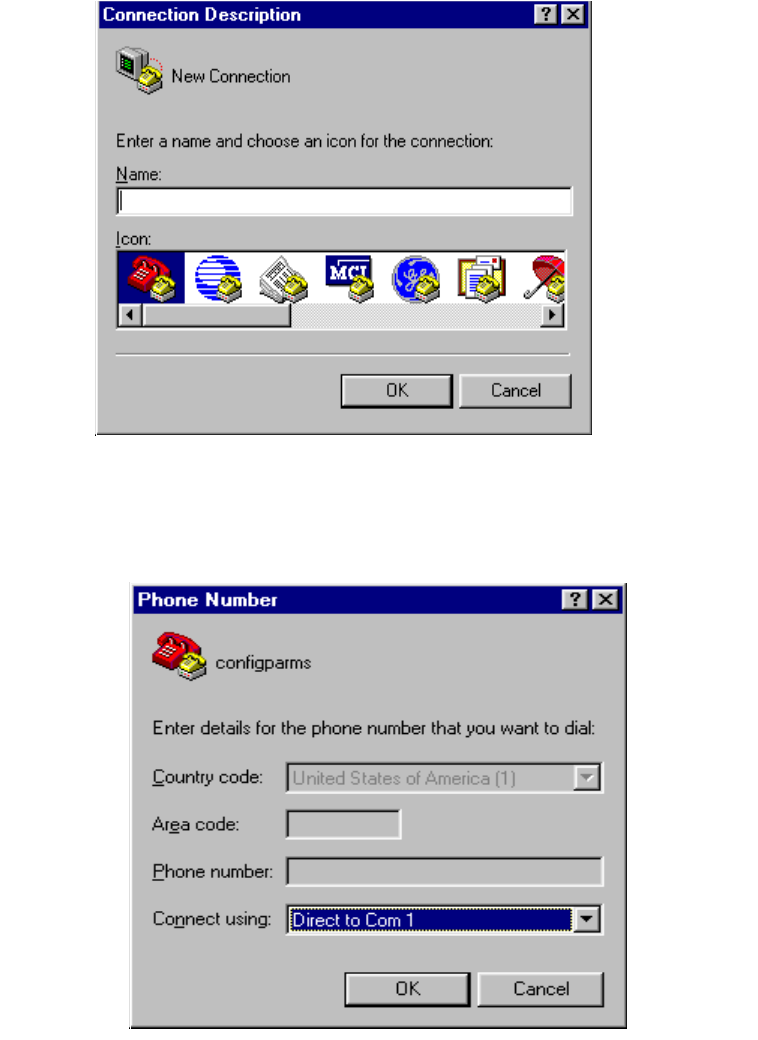
Orion Reader System Guide
9-6 Use or disclosure of Proprietary Information contained on this sheet is subject to the restriction stated on the title page of this document.
Figure 9-2 Connection Description Dialog Box
2. Enter a name for the session (e.g. myCOM1) and click OK.
The application displays the Phone Number dialog box as shown in Figure 9-3.
Figure 9-3 Phone Number Dialog Box
3. From the Connect using pull-down list, choose the COM1 option (or whichever
com port on the PC to which the RS–232 cable is attached) and click OK.
The application displays the COM1 Properties dialog box as shown in
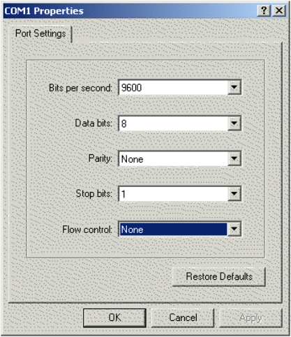
System Diagnostics and Preventive Maintenance
Use or disclosure of Proprietary Information contained on this sheet is subject to the restriction stated on the title page of this document. 9-7
Figure 9-4.
Figure 9-4 COM1 Properties Dialog Box
4. In the pull-down list on the COM1 Properties dialog box, choose the following
settings:
•Bits per second: 9600 baud
•Data bits: 8
•Parity: None
•Stop bits: 1
•Flow control: None
5. Click OK.
The application displays the myCOM1 - Hyper Terminal main screen as shown
in Figure 9-5.
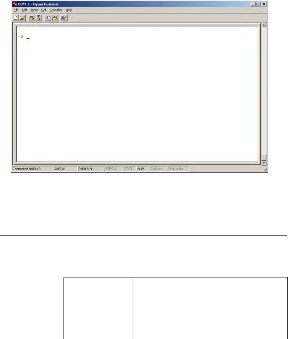
Orion Reader System Guide
9-8 Use or disclosure of Proprietary Information contained on this sheet is subject to the restriction stated on the title page of this document.
.
Figure 9-5 Hyper Terminal Main Screen
6. Press ENTER several times to get a flashing cursor prompt (– > _ ).
You can enter any of the diagnostic commands as listed in Table 9-3.
Diagnostic Commands
The Orion Reader uses the commands outlined in this section to help you diagnose
problems between the host and Orion Reader (Table 9-3).
Table 9-3 Diagnostic Commands
Diagnostic Command Command Description
version Used to display the VxWorks version information and the
boot line parameters. The Orion Reader’s IP address
and subnet mask are shown after the “e=” string.
bootChange Used to change the boot line parameters including the
Orion Reader’s IP address and subnet mask. See the
“bootChange” section for details.

System Diagnostics and Preventive Maintenance
Use or disclosure of Proprietary Information contained on this sheet is subject to the restriction stated on the title page of this document. 9-9
Note: All diagnostic host commands are case sensitive.
ShowErrorLog Scrolls the error log in chronological order.
ClearErrorLog Clears all entries in the error log.
ShowSysStatusBits Shows the status bits for error conditions in the Orion
Reader.
Table 9-3 Diagnostic Commands

Orion Reader System Guide
9-10 Use or disclosure of Proprietary Information contained on this sheet is subject to the restriction stated on the title page of this document.
bootChange
This section describes each line of the bootChange command and provides associated
usage.
Press Enter if you do not want to change an entry. To clear an entry on a line, type a
“.” (period). To change a line, type what is needed, then press Enter. On the “inet on
ethernet (e)” line, enter the Orion Reader’s IP address and subnet mask in the form
xxx.xxx.xxx.xxx.yyyyyyyy where xxx.xxx.xxx.xxx is the Orion Reader’s IP address
in decimal format and yyyyyyyy is the Orion Reader’s subnet mask in hexadecimal
format.
Note: If the Orion Reader’s IP address and subnet mask are not entered in the format
as shown, the Orion Reader’s Ethernet communications may not work.
When you have finished entering the bootChange, the screen displays the following
information:
boot device Required, must be motfec0
processor number Required, must be 0
host name Required, must be lcHost
file name Not required, should be left as is or blank
inet on ethernet (e) !Mandatory: Orion Reader’s IP address and subnet mask must be of the
form xxx.xxx.xxx.xxx:yyyyyyyy
inet on backplane (b) Not required, should be left as is or blank
host inet (h) Required, should be set to IP address of host computer
gateway inet (g) Not required, should be left as is or blank
user (u) Not required, should be left as is or blank
ftp password (pw)
(blank = use rsh) Not required, should be left as is or blank
flags (f) Required, should be 0x0
target name (tn) Not required, should be left as is or blank
startup script (s) Not required, should be left blank
other (o) Not required, should be left as is or blank

System Diagnostics and Preventive Maintenance
Use or disclosure of Proprietary Information contained on this sheet is subject to the restriction stated on the title page of this document. 9-11
Power Cycling the Orion Reader
If the Orion Reader stops communicating with the host system and does not respond
to the RESET READER (0006H) command, try power cycling the reader.
To power cycle the reader
1. Display the version by typing version. This provides the IP addresses for the
Orion Reader.
2. Display the error log by typing ShowErrorLog. Using the Hyper Terminal, save
the error log to a file by selecting Capture Text... from the Transfer drop-down
menu (Figure 9-6). The Capture feature in the menu bar at the bottom of the
screen darkens to show text is captured.
boot device motfec0
processor number 0
host name lcHost
file name
inet on ethernet (e) 10.3.11.96:ffff0000
inet on backplane (b)
host inet (h) 10.3.11.94
gateway inet (g)
user (u)
ftp password (pw)
(blank = use rsh)
flags (f) 0x0
target name (tn)
startup script (s)
other (o)
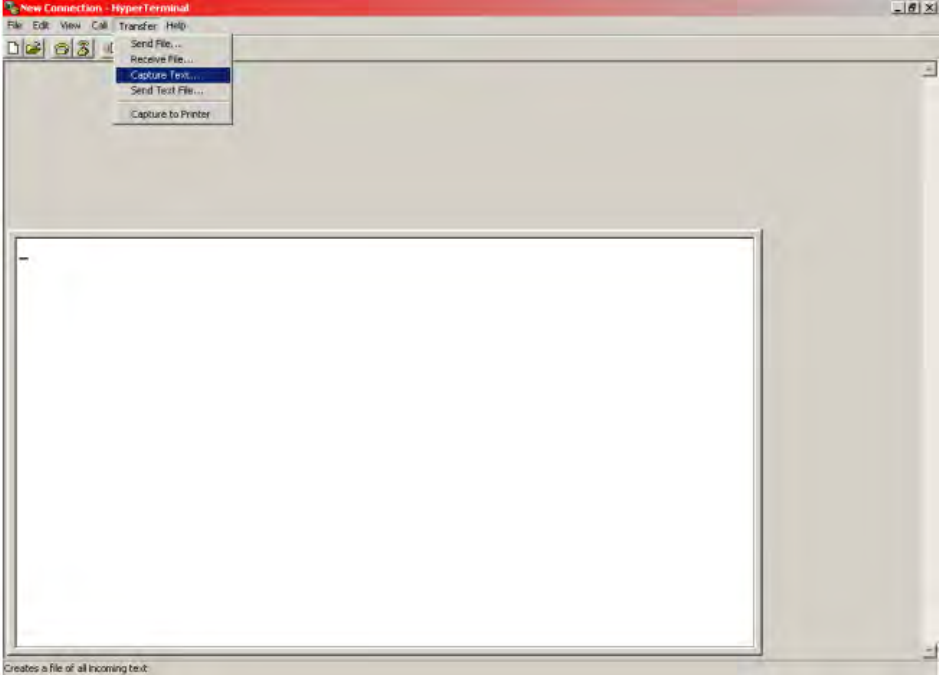
Orion Reader System Guide
9-12 Use or disclosure of Proprietary Information contained on this sheet is subject to the restriction stated on the title page of this document.
Figure 9-6 Capture Text Feature
Stop or pause the error log capture by selecting Capture Text... from the
Transfer drop-down menu by selecting Stop or Pause from the Capture Text...
feature (Figure 9-7).
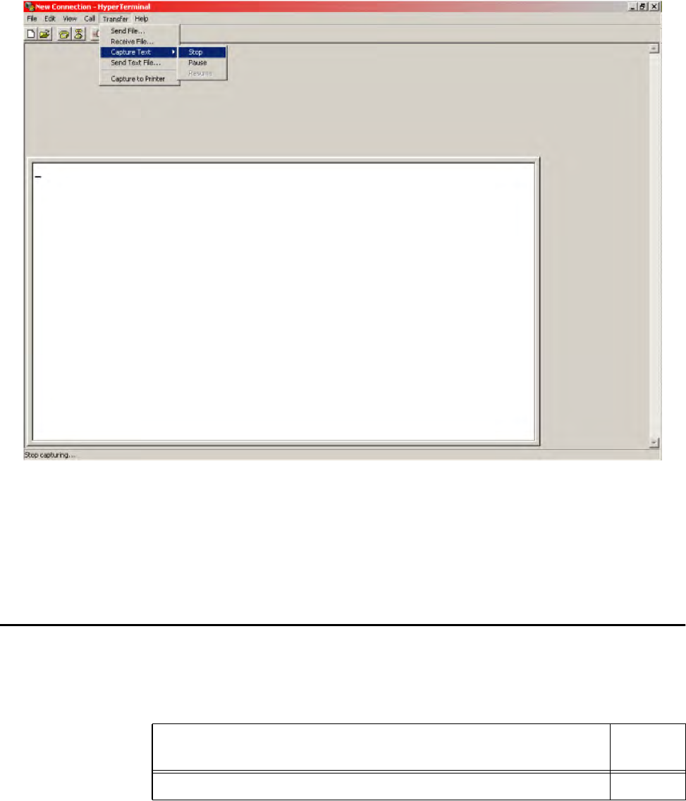
System Diagnostics and Preventive Maintenance
Use or disclosure of Proprietary Information contained on this sheet is subject to the restriction stated on the title page of this document. 9-13
Figure 9-7 Stop or Pause Text Capture
3. Display the error condition status bits by typing ShowSysStatusBits.
4. Disconnect Power.
5. Reconnect Power.
Error Log Reference
This section lists all the error log messages that can occur in the Orion Reader system.
Table 9-4 lists the Orion Reader software module numbers for reference.
Table 9-4 Software Module Numbers
Software Module Module
Number
System Initialization Module 0000H

Orion Reader System Guide
9-14 Use or disclosure of Proprietary Information contained on this sheet is subject to the restriction stated on the title page of this document.
Note: Only those software module error logs that are currently being used in the
Orion Reader are listed here.
Lane Controller Interface Module 0001H
System Interface Module 0002H
Mode Interface Module 0003H
Tag Interface Module 0004H
Sync Module 0005H
Global Positioning System (GPS) Module 0006H
Radio Frequency (RF) Transceiver Interface Module 0007H
Diagnostic Module 0008H
Reserved 0009H
Tag Buffer Module 000AH
Reserved 000BH
Reserved 000CH
Digital I/O (DIO) Module 000DH
Table 9-4 Software Module Numbers (continued)

System Diagnostics and Preventive Maintenance
Use or disclosure of Proprietary Information contained on this sheet is subject to the restriction stated on the title page of this document. 9-15
System Initialization Module Errors
Table 9-5 contains the system initialization module (MSIM) error numbers and log
entry descriptions.
Lane Controller Interface Module Errors
Table 9-6 contains the lane controller interface module (LCIM) error numbers and log
entry descriptions.
Table 9-5 System Initialization Module Errors (0000H)
Log Entry Description Error
Number
Reserved N/A 0000H
Timer Initialization Error This error indicates that the system timer initialization failed.
This error could prevent the Orion Reader’s ability to transact
with tags.
0001H
Buffer Management (BM)
Initialization Error This error indicates that the BM system initialization failed. This
error could prevent the Orion Reader’s ability to transact with
tags.
0002H
Tag Buffer Initialization Error This error indicates that the tag buffer module initialization
failed. 0003H
System Queue Create Error This error indicates that the creation of one or more system
message queues failed. This error could prevent the Orion
Reader’s ability to transact with tags.
0004H
System Task Create Error This error indicates that the creation of one or more system
tasks failed. This error could prevent the Orion Reader’s ability
to transact with tags.
0005H
System Security Error This error indicates that the system security was violated. This
error could prevent the Orion Reader’s ability to transact with
tags.
0006H
Error Recovery Event One or more of the errors recovered. 0007H
Table 9-6 Lane Controller Interface Module Errors (0001H)
Log Entry Description Error
Number
Reserved N/A 0000H
Saved SysComMsgs
Initialization Error This error indicates that the system communication message
buffer initialization failed. This error could prevent the Orion
Reader’s ability to transact with tags.
0001H

Orion Reader System Guide
9-16 Use or disclosure of Proprietary Information contained on this sheet is subject to the restriction stated on the title page of this document.
Buffer Management Create
Queue Error This error indicates that the creation of the LCI BM queue
failed. This error could prevent the Orion Reader’s ability to
transact with tags.
0002H
Buffer Management Not
Initialized Error This error indicates that BM is not initialized. This error could
prevent the Orion Reader’s ability to transact with tags. 0003H
Reserved N/A 0004H
System Serial Device Error This error indicates that the initialization of the system serial
port failed. 0005H
System Message Queue Full
Error This error indicates that the LC Message Queue is full. This
error could prevent the Orion Reader’s ability to transact with
tags.
0006H
Get Buffer Management
Buffer Error This error indicates that the get BM buffer failed. This error
could prevent the Orion Reader’s ability to transact with tags. 0007H
Message Queue Send Error This error indicates that the message queue send failed. This
error could prevent the Orion Reader’s ability to transact with
tags.
0008H
Reserved N/A 0009H
Message Queue Receive
Error This error indicates that the message queue receive failed.
This error could prevent the Orion Reader’s ability to transact
with tags.
000AH
Return Buffer Management
Buffer Error This error indicates that the return BM buffer failed. This error
could prevent the Orion Reader’s ability to transact with tags. 000BH
Reserved N/A 000CH
Reserved N/A 000DH
Reserved N/A 000EH
Reserved N/A 000FH
Tag Buffer Write Error This error indicates that tag data failed to be written into the tag
buffering location in flash memory. 0010H
Tag Buffer Overflow Error This error indicates that there is a tag buffer overflow. 0011H
Tag Buffer State Not Idle
Error This error indicates that the tag buffering runtime state is not
idle. 0012H
Serial Communication Link
Error This error indicates that the serial communication link is down. 0013H
TCP/IP Communication Link
Error This error indicates that the TCP/IP communication link is
down. This error could prevent the Orion Reader’s ability to
transact with tags.
0014H
Reserved N/A 0015H
Error Recovery Event One or more of the errors recovered. 0016H
Table 9-6 Lane Controller Interface Module Errors (0001H) (continued)

System Diagnostics and Preventive Maintenance
Use or disclosure of Proprietary Information contained on this sheet is subject to the restriction stated on the title page of this document. 9-17
System Interface Module Errors
Table 9-7 contains the system interface module (SIM) error numbers and log entry
descriptions.
Table 9-7 System Interface Module Errors (0002H)
Log Entry Description Error
Number
Reserved N/A 0000H
Buffer Management Create
Queue Error This error indicates that the creation of the SI BM queue failed.
This error could prevent the Orion Reader’s ability to transact
with tags.
0001H
Buffer Management Not
Initialized Error This error indicates that BM is not initialized. This error could
prevent the Orion Reader’s ability to transact with tags. 0002H
Message Queue Receive
Error This error indicates that the message queue receive failed.
This error could prevent the Orion Reader’s ability to transact
with tags.
0003H
Return Buffer Management
Buffer Error This error indicates that the return BM buffer failed. This error
could prevent the Orion Reader’s ability to transact with tags. 0004H
Get Buffer Management
Buffer Error This error indicates that the get BM buffer failed. This error
could prevent the Orion Reader’s ability to transact with tags. 0005H
Message Queue Send Error This error indicates that the message queue send failed. This
error could prevent the Orion Reader’s ability to transact with
tags.
0006H
Tag Buffer Read Error This error indicates that tag data failed to be read from the tag
buffering location in flash memory. 0007H
Tag Buffer Overflow Error This error indicates that there is a tag buffer overflow. 0008H
Erase Tag Buffers Error Tags in the Tag Buffer location in Flash failed to erased. 0009H
Erase Entire Tag Buffer
Space Error This error indicates that erase entire tag buffers flash space
failed. 000AH
Wait For Tag Buffer Idle State
Time-out Error This error indicates that the wait for tag buffering runtime idle
state, timed out. 000BH
Reserved N/A 000CH
Error Recovery Event One or more of the errors recovered. 000DH

Orion Reader System Guide
9-18 Use or disclosure of Proprietary Information contained on this sheet is subject to the restriction stated on the title page of this document.
Mode Interface Module Error Numbers
Table 9-8 contains the mode interface module (MIM) error numbers and log entry
descriptions.
Table 9-8 Mode Interface Module Errors (0003H)
Log Entry Description Error
Number
Reserved N/A 0000H
Prior Required Configuration
Not Set Error This error indicates that not all required configuration
parameters are set for the system to be able to start running in
the requested mode. This error could prevent the Orion
Reader’s ability to transact with tags.
0001H
Reserved N/A 0002H
Error Recovery Event One or more of the errors recovered. 0003H
Tag Interface Module Error Numbers
Table 9-9
contains the tag interface module (TIM) error numbers and log entry descriptions.
Table 9-9 Tag Interface Module Errors (0004H)
Log Entry Description Error
Number
Reserved N/A 0000H
TIM System Error This error indicates that a system call failed. This error could
prevent the Orion Reader’s ability to transact with tags. 0001H
FPGA1 Not Ready Error This error indicates that the FPGA1 is not ready. This error
could prevent the Orion Reader’s ability to transact with tags. 0002H
RF Transceiver Not Ready
Error This error indicates that the RF Transceiver is not ready. This
error could prevent the Orion Reader’s ability to transact with
tags.
0003H
FPGA1 Memory Test Error This error indicates that the FPGA1 memory test failed. This
error could prevent the Orion Reader’s ability to transact with
tags.
0004H
FPGA2 Memory Test Error This error indicates that the FPGA2 memory test failed. This
error could prevent the Orion Reader’s ability to transact with
tags.
0005H
Queue Message Error This error indicates that the source of the message is invalid.
This error could prevent the Orion Reader’s ability to transact
with tags.
0006H
Reserved N/A 0007H

System Diagnostics and Preventive Maintenance
Use or disclosure of Proprietary Information contained on this sheet is subject to the restriction stated on the title page of this document. 9-19
TagTransaction Configuration
Command Error This error indicates that an invalid tag transaction configuration
command was sent to the reader. This error could prevent the
Orion Reader’s ability to transact with tags.
0008H
Tag Transaction Sequence
Command Error This error indicates that an invalid tag transaction sequence
command was sent to the reader. This error could prevent the
Orion Reader’s ability to transact with tags.
0009H
Reserved N/A 000AH
Reserved N/A 000BH
Reserved N/A 000CH
Reserved N/A 000DH
Reserved N/A 000EH
Reserved N/A 000FH
Buffer Management Create
Queue Error This error indicates that the creation of a BM queue failed. This
error could prevent the Orion Reader’s ability to transact with
tags.
0010H
Get Buffer Management
Buffer Error This error indicates that the get BM buffer failed. This error
could prevent the Orion Reader’s ability to transact with tags. 0011H
Return Buffer Management
Buffer Error This error indicates that the return BM buffer failed. This error
could prevent the Orion Reader’s ability to transact with tags. 0012H
Get System Queue
Identification (ID) Error This error indicates that getting the system queue identification
failed. This error could prevent the Orion Reader’s ability to
transact with tags.
0013H
Error Recovery Event One or more of the errors recovered. 0014H
Product ID Error This error indicates that the Orion Reader was set to an
unsupported protocol. 0015H
Queue Create Error This error indicates that the message queues create failed. This
error could prevent the Orion Reader’s ability to transact with
tags.
0016H
Task Create Error This error indicates that the creation of a tag interface task
failed. This error could prevent the Orion Reader’s ability to
transact with tags.
0017H
Reserved N/A 0018H
Reserved N/A 0019H
Tag Interface Module
Configuration Initialization
Error
This error indicates that the tag interface configuration
initialization failed. This error could prevent the Orion Reader’s
ability to transact with tags.
001AH
Table 9-9 Tag Interface Module Errors (0004H) (continued)

Orion Reader System Guide
9-20 Use or disclosure of Proprietary Information contained on this sheet is subject to the restriction stated on the title page of this document.
Sync Module Error Numbers
Table 9-10
contains the Sync module (SM) error numbers and log entry descriptions
.
GPS Module Error Numbers
Table 9-11 contains the GPS module (GPSM) error numbers and log entry
descriptions.
Table 9-10 Sync Module Errors (0005H)
Log Entry Description Error
Number
Reserved N/A 0000H
Sync Two Masters Error This error indicates that two readers are configured as masters. 0001H
Sync Master Slave Error This error indicates that a reader, configured as a slave, does
not detect the master. 0002H
Sync Clock Error This error indicates that a Sync clock error occurred. 0003H
GPS Window Error This error indicates that a GPS window error occurred. 0004H
GPS One-PPS Error This error indicates that the one-pulse per second failed. 0005H
Sync Two Masters Error
Recovery Event This event indicates that the two masters error, recovered. 0006H
Sync Master Slave Error
Recovery Event This event indicates that the master slave error, recovered. 0007H
Sync Clock Error Recovery
Event This event indicates that the Sync clock error, recovered. 0008H
GPS Window Error Recovery
Event This event indicates that the GPS Window error, recovered 0009H
GPS One PPS Error
Recovery Event This event indicates that the one-pulse per second, recovered. 000AH
Table 9-11 GPS Module Errors (0006H)
Log Entry Description Error
Number
Reserved N/A 0000H
GPS Communication Link
Error This error indicates that the communication with the GPS
module is down. 0001H
GPS T-RAIM Alarm Set Event This error indicates that the T-RAIM algorithm of the GPS
module failed. 0002H

System Diagnostics and Preventive Maintenance
Use or disclosure of Proprietary Information contained on this sheet is subject to the restriction stated on the title page of this document. 9-21
RF Transceiver Interface Module Error Numbers
Table 9-12 contains the RF transceiver interface module (RFTIM) error numbers and
log entry descriptions.
GPS Self-Test Failed Event This error indicates that the self-test of the GPS module failed. 0003H
GPS Power On Failure Event This error indicates that the GPS module failed the power on
test. 0004H
GPS Auto Survey Failure
Event This error indicates that the auto survey failed. 0005H
GPS Communication Link
Error Recovery Event This event indicates that GPS Communication link, recovered. 0006H
GPS T-RAIM Alarm Set Error
Recovery Event This event indicates that T-RAIM alarm cleared. 0007H
GPS Self-Test Failed
Recovery Event This event indicates that self-test error cleared. 0008H
GPS Power-On Failure
Recovery Event This event indicates that self-test error cleared. 0009H
GPS Auto Survey Failure
Recovery Event This event indicates that the auto survey failure cleared. 000AH
Table 9-11 GPS Module Errors (0006H) (continued)
Table 9-12 RF Transceiver Interface Module Errors (0007H)
Log Entry Description Error
Number
Reserved N/A 0000H
Buffer Management Create
Queue Error This error indicates that the creation of a BM queue failed. This
error could prevent the Orion Reader’s ability to transact with
tags.
0001H
Memory Allocate Error This error indicates that the Memory allocation failed. This error
could prevent the Orion Reader’s ability to transact with tags. 0002H
System Queue ID Retrieve
Error This error indicates that getting the system queue identification
failed. This error could prevent the Orion Reader’s ability to
transact with tags.
0003H
Serial SMC Open Error This error indicates that opening the serial SMC failed. This
error could prevent the Orion Reader’s ability to transact with
tags.
0004H
Connect Interrupt Handler
Error This error indicates that connecting the interrupt handler failed.
This error could prevent the Orion Reader’s ability to transact
with tags.
0005H

Orion Reader System Guide
9-22 Use or disclosure of Proprietary Information contained on this sheet is subject to the restriction stated on the title page of this document.
Enable Interrupt Error This error indicates that enabling the interrupt failed. This error
could prevent the Orion Reader’s ability to transact with tags. 0006H
I/O Semaphore Create Error This error indicates that creating the I/O semaphore failed. This
error could prevent the Orion Reader’s ability to transact with
tags.
0007H
Non-volatile Random Access
Memory (NVRAM)
Configuration Data Retrieve
Error
This error indicates that retrieving configuration data from
NVRAM failed. This error could prevent the Orion Reader’s
ability to transact with tags.
0008H
NVRAM Configuration Data
Corrupt Error This error indicates that the configuration data in NVRAM is
corrupt. This error could prevent the Orion Reader’s ability to
transact with tags.
0009H
NVRAM Configuration Data
Write Error This error indicates that writing configuration data to NVRAM
failed. This error could prevent the Orion Reader’s ability to
transact with tags.
000AH
RF Transceiver Reset Error This error indicates that the transceiver reset failed. This error
could prevent the Orion Reader’s ability to transact with tags. 000BH
RF Heartbeat Task Create
Error This error indicates that the creation of the heartbeat task
failed. This error could prevent the Orion Reader’s ability to
transact with tags.
000CH
Get Buffer Management
Buffer Error This error indicates that the get BM buffer failed. This error
could prevent the Orion Reader’s ability to transact with tags. 000DH
Return Buffer Management
Buffer Error This error indicates that the return BM buffer failed. This error
could prevent the Orion Reader’s ability to transact with tags. 000EH
Serial Command Code Error This error indicates that an invalid command was received.
This error could prevent the Orion Reader’s ability to transact
with tags.
000FH
Message Queue Send Error This error indicates that the message queue send failed. This
error could prevent the Orion Reader’s ability to transact with
tags.
0010H
Set Tx Attenuation (Attn)
Invalid Input Error This error indicates that invalid input was sent to the reader for
setting the Tx Attn. This error could prevent the Orion Reader’s
ability to transact with tags.
0011H
Set Rx Attn Invalid Input Error This error indicates that invalid input was sent to the reader for
setting the Rx Attn. This error could prevent the Orion Reader’s
ability to transact with tags.
0012H
Set Range Adjust Invalid
Input Error This error indicates that invalid input was sent to the reader for
setting the Range Adjust. This error could prevent the Orion
Reader’s ability to transact with tags.
0013H
Set Protocol Parameters
Invalid Input Error This error indicates that invalid input was sent to the reader for
setting the protocol parameters. This error could prevent the
Orion Reader’s ability to transact with tags.
0014H
Table 9-12 RF Transceiver Interface Module Errors (0007H) (continued)

System Diagnostics and Preventive Maintenance
Use or disclosure of Proprietary Information contained on this sheet is subject to the restriction stated on the title page of this document. 9-23
Set Frequency Invalid Input
Error This error indicates that invalid input was sent to the reader for
setting the frequency. This error could prevent the Orion
Reader’s ability to transact with tags.
0015H
Reserved N/A 0016H
Reserved N/A 0017H
Reserved N/A 0018H
Reserved N/A 0019H
Reserved N/A 001AH
Reserved N/A 001BH
Message Queue Receive
Error This error indicates that the message queue receive failed.
This error could prevent the Orion Reader’s ability to transact
with tags.
001CH
Error Recovery Event One or more of the errors recovered. 001DH
Task Create Error This error indicates that the creation of an RF transceiver task
failed. This error could prevent the Orion Reader’s ability to
transact with tags.
001EH
Queue Create Error This error indicates that the message queues create failed.
This error could prevent the Orion Reader’s ability to transact
with tags.
001FH
Invalid Operation Mode
Initialization This error indicates that the RF transceiver interface module
was given an invalid mode number. This error could prevent the
Orion Reader’s ability to transact with tags.
0040H
Transceiver Serial
Communication Error This error indicates that a serial communication link is down. 0041H
Transceiver Reset Error This error indicates that the transceiver reset failed upon
initialization. This error could prevent the Orion Reader’s ability
to transact with tags.
0042H
Frequency Initialization Error This error indicates that the frequency initialization failed. This
error could prevent the Orion Reader’s ability to transact with
tags.
0043H
Tx Attenuation Initialization
Error This error indicates that the transmit attenuation initialization
failed. This error could prevent the Orion Reader’s ability to
transact with tags.
0044H
Rx Attenuation Initialization
Error This error indicates that the receive attenuation initialization
failed. This error could prevent the Orion Reader’s ability to
transact with tags.
0045H
Data Detect Initialization
Error This error indicates that the data detect initialization failed. This
error could prevent the Orion Reader’s ability to transact with
tags.
0046H
Table 9-12 RF Transceiver Interface Module Errors (0007H) (continued)

Orion Reader System Guide
9-24 Use or disclosure of Proprietary Information contained on this sheet is subject to the restriction stated on the title page of this document.
13-MHz Disable Initialization
Error This error indicates that there is a 13-MHz disable error. This
error could prevent the Orion Reader’s ability to transact with
tags.
0047H
RF Transceiver ADC Above
Maximum Error This error indicates that the analog-to-digital converter (ADC)
in the control feedback loop has exceeded a maximum set
value. This error could prevent the Orion Reader’s ability to
transact with tags.
0201H
RF Transceiver ADC Below
Minimum Error This error indicates that the ADC in the control feedback loop
has fallen below a minimum set value. This error could prevent
the Orion Reader’s ability to transact with tags.
0202H
RF Transceiver Attn DAC1
Above Maximum Error This error indicates that the attenuation DAC for source 1 has
exceeded a maximum set value. This error could prevent the
Orion Reader’s ability to transact with tags.
0203H
RF Transceiver Attn DAC1
Below Minimum Error This error indicates that the attenuation DAC for source 1 has
fallen below a minimum set value. This error could prevent the
Orion Reader’s ability to transact with tags.
0204H
RF Transceiver Attn DAC2
Above Maximum Error This error indicates that the attenuation DAC for source 2 has
exceeded a maximum set value. This error could prevent the
Orion Reader’s ability to transact with tags.
0205H
RF Transceiver Attn DAC2
Below Minimum Error This error indicates that the attenuation DAC for source 2 has
fallen below a minimum set value. This error could prevent the
Orion Reader’s ability to transact with tags.
0206H
RF Transceiver Depth-of-
Modulation (DOM) DAC
Above Maximum Error
This error indicates that the depth of modulation DAC has
exceeded a maximum set value. This error could prevent the
Orion Reader’s ability to transact with tags.
0207H
RF Transceiver DOM DAC
Below Minimum Error This error indicates that the depth of modulation DAC has fallen
below a minimum set value. This error could prevent the Orion
Reader’s ability to transact with tags.
0208H
RF Transceiver Source1 PLL
Unlocked Error This error indicates that the source 1 phase lock loop is
unlocked. This error could prevent the Orion Reader’s ability to
transact with tags.
0209H
RF Transceiver Source2 PLL
Unlocked Error This error indicates that the source 2, phase lock loop is
unlocked. This error could prevent the Orion Reader’s ability to
transact with tags.
020AH
RF Transceiver 13-MHz
Control Error This error indicates that there is a 13-MHz Control error. This
error could prevent the Orion Reader’s ability to transact with
tags.
020BH
RF Transceiver 5V DC Fault
Error This error indicates that the 5VDC digital supply is above or
below the threshold. This error could prevent the Orion
Reader’s ability to transact with tags.
020CH
RF Transceiver Uncalibrated
Error This error indicates that the Transceiver is uncalibrated. This
error could prevent the Orion Reader’s ability to transact with
tags.
020DH
Reserved N/A 020EH
Table 9-12 RF Transceiver Interface Module Errors (0007H) (continued)

System Diagnostics and Preventive Maintenance
Use or disclosure of Proprietary Information contained on this sheet is subject to the restriction stated on the title page of this document. 9-25
RF Transceiver 5V DC
Undervoltage Error This error indicates that the 5VDC digital supply is below the
threshold. This error could prevent the Orion Reader’s ability to
transact with tags.
020FH
Nack From RF Error This error indicates that the digital board received a Nack from
the Transceiver board. This error could prevent the Orion
Reader’s ability to transact with tags.
0401H
Serial Command Time-out
Error This error indicates that the digital board failed to send data to
the Transceiver board. This error could prevent the Orion
Reader’s ability to transact with tags.
0402H
Reserved N/A 0403H
Set Tx Attn Command Failure
Error This error indicates that the “Set Tx Attn Command” failed. This
error could prevent the Orion Reader’s ability to transact with
tags.
0404H
Get Tx Attn Command Failure
Error This error indicates that the “Get Tx Attn Command” failed.
This error could prevent the Orion Reader’s ability to transact
with tags.
0405H
Set Rx Attn Command Failure
Error This error indicates that the “Set Rx Attn Command” failed.
This error could prevent the Orion Reader’s ability to transact
with tags.
0406H
Get Rx Attn Command
Failure Error This error indicates that the “Get Rx Attn Command” failed.
This error could prevent the Orion Reader’s ability to transact
with tags.
0407H
Set Range Adjust Command
Failure Error This error indicates that the “Set Range Adjust Command”
failed. This error could prevent the Orion Reader’s ability to
transact with tags.
0408H
Get Range Adjust Command
Failure Error This error indicates that the “Get Range Adjust Command”
failed. This error could prevent the Orion Reader’s ability to
transact with tags.
0409H
Set Protocol Parameters
Command Failure Error This error indicates that the “Set Protocol Parameters
Command” failed. This error could prevent the Orion Reader’s
ability to transact with tags.
040AH
Get Protocol Parameters
Command Failure Error This error indicates that the “Get Protocol Parameters
Command” failed. This error could prevent the Orion Reader’s
ability to transact with tags.
040BH
Set Frequency Command
Failure Error This error indicates that the “Set Frequency Command” failed.
This error could prevent the Orion Reader’s ability to transact
with tags.
040CH
Get Frequency Command
Failure Error This error indicates that the “Get Frequency Command” failed.
This error could prevent the Orion Reader’s ability to transact
with tags.
040DH
Get Firmware ID Command
Failure Error This error indicates that the “Get Firmware ID Command”
failed. This error could prevent the Orion Reader’s ability to
transact with tags.
040EH
Table 9-12 RF Transceiver Interface Module Errors (0007H) (continued)

Orion Reader System Guide
9-26 Use or disclosure of Proprietary Information contained on this sheet is subject to the restriction stated on the title page of this document.
Diagnostic Module Error Numbers
Table 9-13 contains the diagnostic module (DM) error numbers and log entry descrip-
tions.
Get Status Command Failure
Error This error indicates that the “Get Status Command” failed. This
error could prevent the Orion Reader’s ability to transact with
tags.
040FH
13-MHz Control Command
Failure Error This error indicates that the “13-MHz Control Command” failed.
This error could prevent the Orion Reader’s ability to transact
with tags.
0410H
RF Transceiver Reset
Command Failure Error This error indicates that the “RF Transceiver Reset Command”
failed. This error could prevent the Orion Reader’s ability to
transact with tags.
0411H
Reference Synchronization
Command Failure Error This error indicates that the “Reference Synchronization
Command” failed. This error could prevent the Orion Reader’s
ability to transact with tags.
0412H
Table 9-12 RF Transceiver Interface Module Errors (0007H) (continued)
Table 9-13 Diagnostic Module Error Numbers (0008H)
Log Entry Description Error
Number
Reserved N/A 0000H
Buffer Management Create
Queue Error This error indicates that the creation of a BM queue failed. 0001H
Memory Allocate Error This error indicates that allocation of memory failed. 0002H
System Queue ID Retrieve
Error This error indicates that getting the system queue identification
failed. 0003H
Connect Interrupt Handler
Error This error indicates that connecting the interrupt handler failed. 0004H
Enable Interrupt Error This error indicates that enabling the interrupt failed. 0005H
Get Buffer Management
Buffer Error This error indicates that the get BM buffer failed. 0006H
Return Buffer Management
Buffer Error This error indicates that the return BM buffer failed. 0007H
Illegal Command Code Error This error indicates that illegal command was sent to the
reader for setting the frequency. 0008H
Message Queue Send Error This error indicates that the message queue send failed. 0009H
Message Queue Receive
Error This error indicates that the message queue receive failed. 000AH

System Diagnostics and Preventive Maintenance
Use or disclosure of Proprietary Information contained on this sheet is subject to the restriction stated on the title page of this document. 9-27
Tag Buffer Module Error Numbers
Table 9-14 contains the tag buffer module (TBM) error numbers and log entry
descriptions.
WatchDog Create Error This error indicates that creation of a watchdog timer failed. 000BH
WatchDog Start Error This error indicates that starting a watchdog timer failed. 000CH
Power On or Reset Event This error indicates that a power on or reset event occurred.
This error could prevent the Orion Reader’s ability to transact
with tags.
000DH
Power Supply Fault Error This error indicates that a power supply fault occurred. This
error could prevent the Orion Reader’s ability to transact with
tags.
000EH
Digital Board OverVoltage
Error This error indicates that an overvoltage fault occurred on the
digital board power supply. This error could prevent the Orion
Reader’s ability to transact with tags.
000FH
Digital Board UnderVoltage
Error This error indicates that an undervoltage fault occurred on the
digital board power supply. This error could prevent the Orion
Reader’s ability to transact with tags.
0010H
Reserved N/A 0011H
Power Supply Fault Status
Error This error indicates that an invalid power supply fault occurred.
This error could prevent the Orion Reader’s ability to transact
with tags.
0012H
Power Supply Fault Source
Error This error indicates that an erroneous power supply fault
occurred. This error could prevent the Orion Reader’s ability to
transact with tags.
0013H
Error Recovery Event One or more of the errors recovered. 0014H
Table 9-13 Diagnostic Module Error Numbers (0008H) (continued)
Table 9-14 Tag Buffer Module Errors (000AH)
Log Entry Description Error
Number
Reserved N/A 0000H
Tag Buffer Threshold Error This error indicates that there is a tag buffer threshold error. 0001H
Error Recovery Event One or more of the errors recovered. 0002H

Orion Reader System Guide
9-28 Use or disclosure of Proprietary Information contained on this sheet is subject to the restriction stated on the title page of this document.
Digital Input/Output Module Error Numbers
Table 9-15 contains the digital input/output module (DIOM) error numbers and log
entry descriptions.
Table 9-15 Digital I/O Module Errors (000DH)
Log Entry Description Error
Number
Reserved N/A 0000H
DIOM Task Create Error This error indicates that the creation of the digital I/O task
failed. This error could prevent the Orion Reader’s ability to
transact with tags.
0001H
Buffer Management Create
Queue Error This error indicates that the creation of a BM queue failed. This
error could prevent the Orion Reader’s ability to transact with
tags.
0002H
Get Buffer Management
Buffer Error This error indicates that the get BM buffer failed. This error
could prevent the Orion Reader’s ability to transact with tags. 0003H
Return Buffer Management
Buffer Error This error indicates that the return BM buffer failed. This error
could prevent the Orion Reader’s ability to transact with tags. 0004H
DIOM Synchronization Error This error indicates that there is a synchronization error. This
error could prevent the Orion Reader’s ability to transact with
tags.
0005H
Message Queue Create Error This error indicates that the message queues create failed.
This error could prevent the Orion Reader’s ability to transact
with tags.
0006H
Message Queue Send Error This error indicates that the message queue send failed. This
error could prevent the Orion Reader’s ability to transact with
tags.
0007H
Message Queue Receive
Error This error indicates that the message queue receive failed.
This error could prevent the Orion Reader’s ability to transact
with tags.
0008H
DIOM Invalid Configuration
Error This error indicates that there is an invalid configuration
command error. This error could prevent the Orion Reader’s
ability to transact with tags.
0009H
DIOM Event Error This error indicates that there is an invalid event error. 000AH
DIOM Synchronization Error
Recovery Event One or more of the synchronization errors recovered. 000BH
Error Recovery Event One or more of the errors recovered. 000CH

System Diagnostics and Preventive Maintenance
Use or disclosure of Proprietary Information contained on this sheet is subject to the restriction stated on the title page of this document. 9-29
Hardware Preventive Maintenance and Troubleshooting
Procedures
The Orion Reader system has limited serviceable parts, however, there are preventive
maintenance steps that can help to keep the equipment operating to specification. This
section describes the preventive maintenance steps and troubleshooting techniques
that can help determine if a component is failing.
Hardware Preventive Maintenance Schedule
Table 9-16 lists the schedule of preventive maintenance activities for the Orion
Reader system components.
Visual Inspection
The Orion Reader system is very reliable, so any service-related problems most likely
will be due to external causes, such as damage to components. Visually inspect each
system component and replace or repair components, if serviceable, as needed.
To perform a visual inspection
1. Inspect the transmit/receive antenna for signs of damage or corrosion.
2. Check cables between the transmit/receive antenna and the Orion Reader. Look
for damage or loose connections.
Table 9-16 Preventive MaintenanceTask Schedule
Period Task Description
Weekly Visually inspect the antennas for physical damage, such as
cracks or stressed cables.
Quarterly Visually inspect all transmit/receive antenna cables for signs of
damage or water invasion.
Semiannually Check the lane configuration. See Chapter 9 for detailed lane
configuration settings.
The toll antennas have two weep holes located at the lower left
and right corners of the radome. Check that these holes are
open to allow any trapped water to drain from the antenna.
Note If the antennas are installed upside down (Star Systems
logo is upside down) drill two new weep holes in the
lower left and right corners of the radome.
Annually Check NEMA enclosure seal for signs of damage or water
invasion.
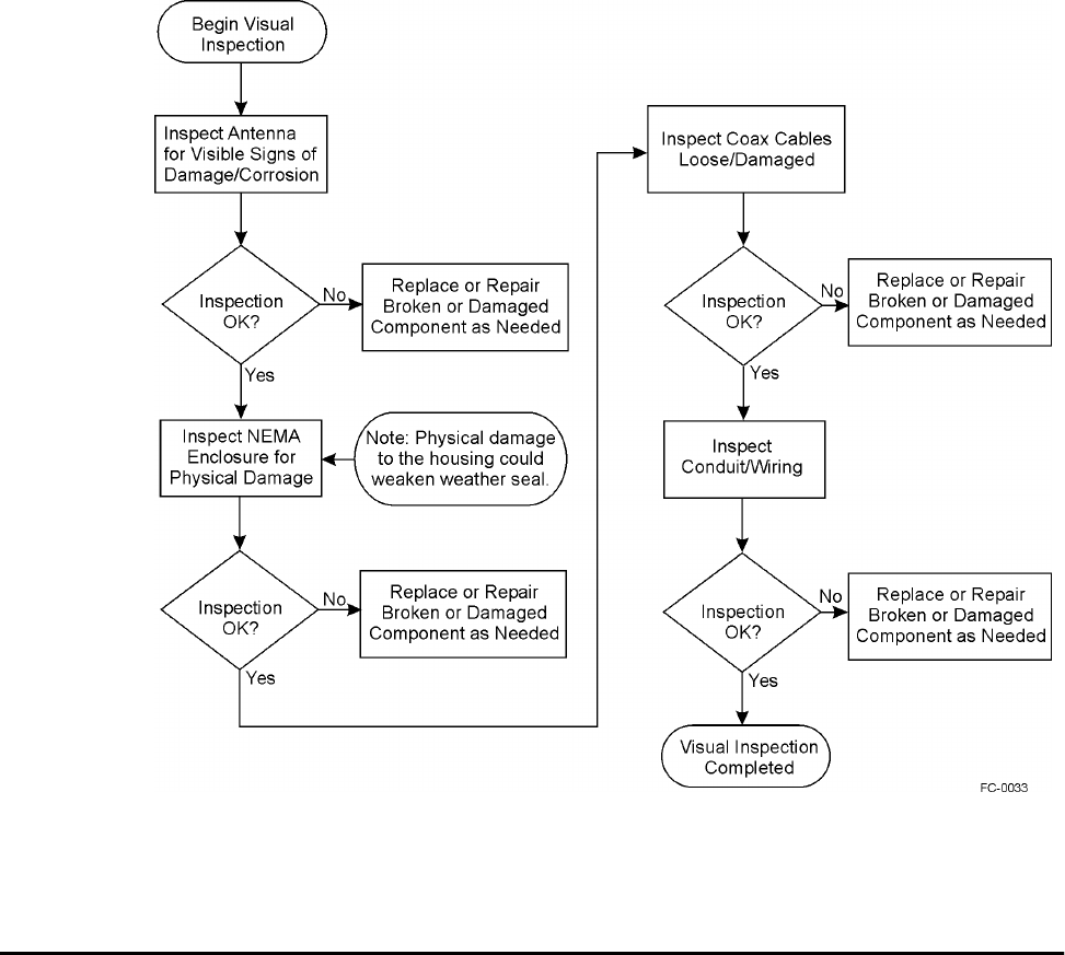
Orion Reader System Guide
9-30 Use or disclosure of Proprietary Information contained on this sheet is subject to the restriction stated on the title page of this document.
Figure 9-8 shows the visual inspection process.
Figure 9-8 Visual Inspection Process
Replacement Instructions for Orion Reader and AVI
Equipment
This section explains how to replace an Orion Reader and other AVI equipment. This
section shows Orion Readers that are installed in NEMA enclosures at the factory.
These instructions provide the following:
•Replacement instructions for an Orion in a NEMA enclosure
•Replacement instructions for a transmit/receive antenna
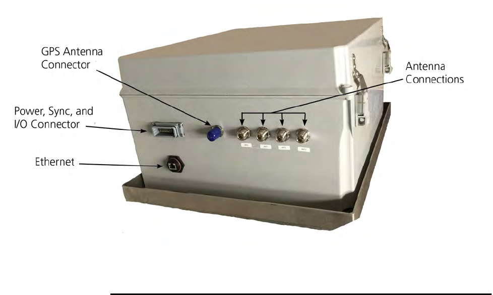
System Diagnostics and Preventive Maintenance
Use or disclosure of Proprietary Information contained on this sheet is subject to the restriction stated on the title page of this document. 9-31
Figure 9-9 shows the basic Orion Reader and its connection ports.
Figure 9-9 Connector and Indicator Locations on the Orion Reader
Replacing a Transmit/Receive Antenna on a
Gantry
To remove an antenna
1. Close traffic lane below where the antenna is being replaced.
2. Shut off RF power to the antenna.
3. Use an inclinometer to record the antenna angle from horizontal before moving
it.
4. Cut off the shrink tubing from around the RF coaxial cable connector.
5. Disconnect the RF connector from the rear of the antenna.
6. Remove nuts and washers from U-bolts.
7. Remove antenna from mounting pipe.
8. Return antenna to Star Systems.
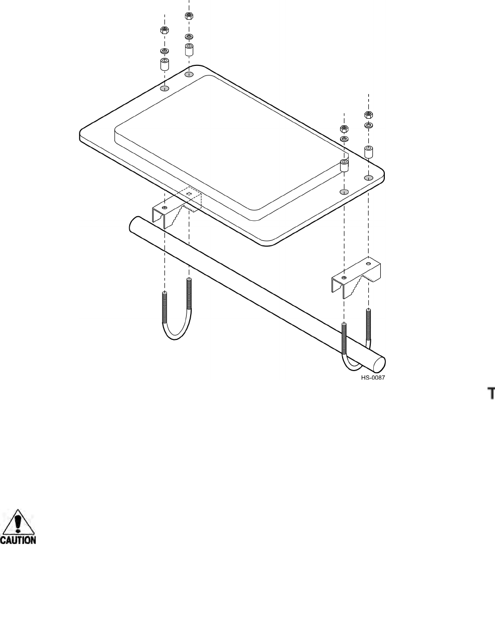
Orion Reader System Guide
9-32 Use or disclosure of Proprietary Information contained on this sheet is subject to the restriction stated on the title page of this document.
Figure 9-10 Transmit/Receive Antenna Mounting and Connections
To install a Transmit/Receive Antenna
1. Place the antenna below the mounting pipe and insert a U-bolt around the pole
and down through the bracket on the side of the antenna closest to the center of
the lane. This antenna should be mounted toward the driver side of the traffic
lane. Place a spacer, lock washer, and nut over each end of the U-bolt, but do not
tighten the nuts. Repeat for the other U-bolt (Figure 9-10).
Caution
When installing the antenna use only the mounting hardware provided. Do not use
oversized washers to secure the plastic radome to the bracket. This practice can
weaken the radome material.
System Diagnostics and Preventive Maintenance
Use or disclosure of Proprietary Information contained on this sheet is subject to the restriction stated on the title page of this document. 9-33
2. Rotate the antenna up and toward oncoming traffic. Rotate up 15° from
horizontal for a dedicated lane or 10° up for a mixed-use lane. Use an
inclinometer or angle finder to check the angle.
3. Tighten nuts with a torque wrench to 50 ft-lb (68 N-m).
4. Slide the shrink tubing over the coaxial cable, but do not heat it.
5. Connect the coaxial cable to the antenna. Heat the shrink tubing at the back of the
antenna after configuring the lane.
Preventive Maintenance Schedule
Table 9-17 lists the schedule of preventive maintenance activities for the Orion Reader
components.
Removal and Replacement Procedures
This section outlines the procedures to remove or replace the Orion Reader compo-
nents.
Transmit/Receive Antenna
Removal
To remove a transmit/receive antenna
1. Switch off power to the Orion Reader and disconnect the antenna from the port.
2. Remove shrink tubing covering connector.
3. Disconnect the antenna cable from the antenna.
4. Check the antenna mounting angle using an inclinometer and record the angle.
Also, note the position of any spacers on the mounting bracket.
5. Remove the nuts holding the mounting bracket U-bolts, then remove the antenna.
6. When lane tuning is complete, use a heat gun to shrink the tubing covering the
antenna cable connections.
Table 9-17 Preventive Maintenance Schedule
Period Task Description
Weekly Visually inspect the antennas and NEMA enclosure for physical
damage such as cracks or stressed cables.
Quarterly Visually inspect all antenna and cables entering NEMA
enclosure for signs of damage or water invasion.
Semiannually Check the lane configuration. See Chapter 9, “Configuring the
Lane.”

Orion Reader System Guide
9-34 Use or disclosure of Proprietary Information contained on this sheet is subject to the restriction stated on the title page of this document.
Replacement
To install a replacement antenna
1. Position the new antenna along the mounting pipe.
2. Insert the U-bolts through the mounting brackets and secure with lock washers
and nuts. Replace any spacers in the same position as before.
3. Set the antenna mounting angle to match the original antenna.
4. Tighten the mounting nuts to 50 ft-lb (68 N-m).
5. Put a length of heat shrink tubing over the antenna cable and connect the cable to
the antenna.
6. Connect the RF cable to the Orion Reader.
7. Check the lane tuning.
8. When lane tuning is complete, use a heat gun to shrink the tubing covering the
antenna cable connection.
Antenna Cable
Removal
To remove an antenna cable
1. Switch off power to the Orion Reader.
2. Disconnect the antenna cable from the Orion Reader antenna port.
3. Remove antenna cable from installation site. Because each installation may differ
(e.g., cabling may be located inside or alongside mounting pipes), detailed
removal instructions are not provided here.
Replacement
To install a replacement antenna cable
1. Route the new antenna cable between the antenna and Orion Reader as needed.
2. Connect the new cable to the Orion Reader at the antenna port.
3. Place a piece of heat shrink tubing over the antenna cable.
4. Connect the cable to the antenna.
5. Switch on power to the Orion Reader.
6. Check the lane tuning.
7. When lane tuning is complete, heat the shrink tubing covering the antenna cable
connector.

A
Acronyms and Glossary

Acronyms and Glossary
Use or disclosure of Proprietary Information contained on this sheet is subject to the restriction stated on the title page of this document. A-3
Appendix A
Acronyms and Glossary
Acronyms and Glossary
A
Aamp(s)
A/V audio/visual
AC alternating current
ACK acknowledge (data valid)
ADC analog-to-digital converter
antenna passive device that converts RF energy into magnetic energy (RF signal)
APP application
ASCII American Standard Code for Information Interchange
AVI automatic vehicle identification
AWG American Wire Gauge
B
backscatter portion of an RF signal that is modulated by a tag and radiated back to the reader
baud measure of number of bits per second of a digital signal; for example, 9600
baud = 9600 bits per second
BCM buffer control mode
bit The smallest unit of information, consisting of a 0 or 1, that is formed from a binary
digit
byte binary character; for example, one 8-bit ASCII character
C
CCentigrade
cm centimeter(s)
Orion Reader System Guide
A-4 Use or disclosure of Proprietary Information contained on this sheet is subject to the restriction stated on the title page of this document.
CMD command
command data set that is recognized by the receiving device as intending to elicit a specific
response
CPU central processing unit
CR carriage return
CRC cyclic redundancy check
crossover cable Ethernet cable equivalent of a null modem for serial cables. The crossover cable is
used so that two systems that use the same transmit and receive pins on the RJ-45 con-
nector can communicate.
CS commission status
CSN command sequence number
CTRL control
CTS clear to send
CVISN Commercial Vehicle Information Systems and Networks application, an ASTM Draft
6 Specification
CW continuous wave
D
DAC digital-to-analog converter
data information that is processed by a computing device
DC direct current
dB decibel(s)
dBidecibel(s), referencing isotropic radiator
DIAG diagnostic (command)
DIO digital input/output
DIOM digital input/output module
DL downlink
DLL dynamic link library
DM diagnostic module
DOM depth of modulation
DSR data set ready
Acronyms and Glossary
Use or disclosure of Proprietary Information contained on this sheet is subject to the restriction stated on the title page of this document. A-5
DTR data terminal ready
E
ECP error correcting protocol
EEPROM electrically erasable programmable read-only memory
eom end of message
EPC electronic product code
ERR error
ESD electrostatic discharge
ETC electronic toll collection
Ethernet family of computer networking technologies for local area network (LAN) and larger
networks
F
ffrequency
FFarenheit
FCC Federal Communications Commission
field physical area/space in which a tag can be read by the reader; also, an element of a data
record/frame, for example, division within a tag's data frame
FIFO first-in, first-out
FPGA field programmable gate-array
frame consecutive bits of data in memory that are read and written as a group
frequency bands range of RF frequencies assigned for transmission by an RF device
ft foot or feet
ftp file transfer protocol
G
Gantenna gain referenced to an isotropic radiator
Ggiga (109)
Gen Ack general acknowledgment
GHz gigahertz
Orion Reader System Guide
A-6 Use or disclosure of Proprietary Information contained on this sheet is subject to the restriction stated on the title page of this document.
GND ground
GPS global positioning system
GPSM GPS module
GSE group select equals
H
hex hexadecimal
hexadecimal base 16 numbering system that uses the characters 0 through 9 and A through F to rep-
resent the digits 0 through 15
HH hours
hh hundredths of seconds
host device, generally a computer, that is connected to reader system components through
the communications port
Hz hertz
I
IC Industry Canada
I/O Input/output
IAG Interagency Group
ID identification; for example, encoded information unique to a particular tag, or an FCC
identifier number
IEC/EN International Electrotechnical Commission/Comite, Europe, en de Normalisation
IHL Internet protocol header length
in inch(es)
interface connection point for communications with another device
IP Internet protocol
ISTHA Illinois State Toll Highway Authority
K
kkilo (103)
kg kilogram(s)
Acronyms and Glossary
Use or disclosure of Proprietary Information contained on this sheet is subject to the restriction stated on the title page of this document. A-7
kHz kilohertz
L
Luniqueness counter timing feature
LAN local area network
lane controller device that is used to integrate all activity that occurs in a toll lane
lb pound(s)
LC lane controller
LCD liquid crystal display
LCIM lane controller interface module
LED light-emitting diode
LF line feed
LSB least significant byte
LSW least significant word
M
smicrosecond(s)
mmeter(s)
Mmillion (106)
mA milliamp(s)
MB megabyte(s)
message combination of fields, frames, and pages as required by the system to transmit or
receive associated command and response data to and from the reader and host com-
puter
MHz megahertz
milli one-thousandth (10-3)
MIM mode interface module
ML mounting location
mode method of operation
MPI multiprotocol interrogator
Orion Reader System Guide
A-8 Use or disclosure of Proprietary Information contained on this sheet is subject to the restriction stated on the title page of this document.
MPR multiprotocol reader
ms milliseconds
MSB most significant byte
MSIM system initialization module
MSW most significant word
mW milliwatt(s)
N
N-m Newton-meter(s)
NACK negative acknowledge
NEMA National Electrical Manufacturers Association
NIC network interface card
null modem a communications cable that allows you to connect to another PC or serial device
using modem protocol.
NVRAM non-volatile random access memory
O
ORT open road tolling
OSHA Occupational Safety and Health Administration
P
Pantenna input power
P/N part number
PC personal computer
PLL phase-lock loop
PPS pulse-per-second
protocol specified convention for the format of data messages communicated between devices
pw password
PWA printed wiring assembly
Acronyms and Glossary
Use or disclosure of Proprietary Information contained on this sheet is subject to the restriction stated on the title page of this document. A-9
R
read process of acquiring data from a device, for example, from a tag or from computer
memory
reader controlled interrogating device capable of acquiring data from a device, for example,
acquiring and interrupting data from a tag
read zone physical area in which a tag can be read by the reader system
RESP response
RF radio frequency
RFID radio frequency identification
RFTIM RF transceiver interface module
RI ring indicator
RMS root-mean-square
RSD received line signal detect
RTS request to send
RX receive data
RXD receive data
S
ssecond(s)
S/N serial number
SA source address
S-record an S-record file consists of a sequence of specially formatted ASCII character strings.
An S-record is less than or equal to 78 bytes.
seq sequence
Ser Num serial number
SI system interface (command)
SIM system interface module
SL step-lock
SM sync module
SMA sub-miniature A connectorr
Orion Reader System Guide
A-10 Use or disclosure of Proprietary Information contained on this sheet is subject to the restriction stated on the title page of this document.
SMC serial management controller
SN serial number
som start of message
step-lock a specific method of synchronizing RFID signals to eliminate or reduce the effect of
interference among colocated RFID readers
sync refers to the synchronization of multiple readers in proximity of each other
system a reader, RF module, antenna, and tag, which are described by the general application
and interfaces with each other and any connected devices that are defined as being
outside the system
T
tag small, self-contained device acting as an identifying transponder
TBM tag buffer module
TCP transmission control protocol
TIM tag interface module
Title 21 state of California code of regulations, Chapter 16, Title 21, which is the standard used
for AVI/DSRC (digital short-range communications) protocol
TM traffic management
toll any application of the system equipment wherein the equipment is used to assist in the
orderly collection of money in exchange for the passage of a vehicle through a partic-
ular installation point
T-RAIM Timing-Receiver Autonomous Integrity Monitoring
transponder a tag
TX transmit data
TXD transmit data
som start of message
step-lock a specific method of synchronizing RFID signals to eliminate or reduce the effect of
interference among colocated RFID readers
system a reader, RF module, antenna, and tag, which are described by the general application
and interfaces with each other and any connected devices that are defined as being
outside the system
Acronyms and Glossary
Use or disclosure of Proprietary Information contained on this sheet is subject to the restriction stated on the title page of this document. A-11
T
tag small, self-contained device acting as an identifying transponder
TCP transmission control protocol
TBM tag buffer module
TDM time-division multiplexing, used in this document to refer to the use of time-division
multiplexing of multiple readers in proximity of each other.
TDMM TDM module
TIM tag interface module
Title 21 state of California code of regulations, Chapter 16, Title 21, which is the standard used
for AVI/DSRC (digital short-range communications) protocol
TM traffic management
toll any application of the system equipment wherein the equipment is used to assist in the
orderly collection of money in exchange for the passage of a vehicle through a partic-
ular installation point
T-RAIM Timing-Receiver Autonomous Integrity Monitoring
transponder a tag
TX transmit data
TXD transmit data
Orion Reader System Guide
A-12 Use or disclosure of Proprietary Information contained on this sheet is subject to the restriction stated on the title page of this document.
U
UL uplink
V
Vvolt(s)
V. Class vehicle class
VCC voltage controlled current
Ver version (software)
W
Wwatt(s)

B
Hardware Interfaces
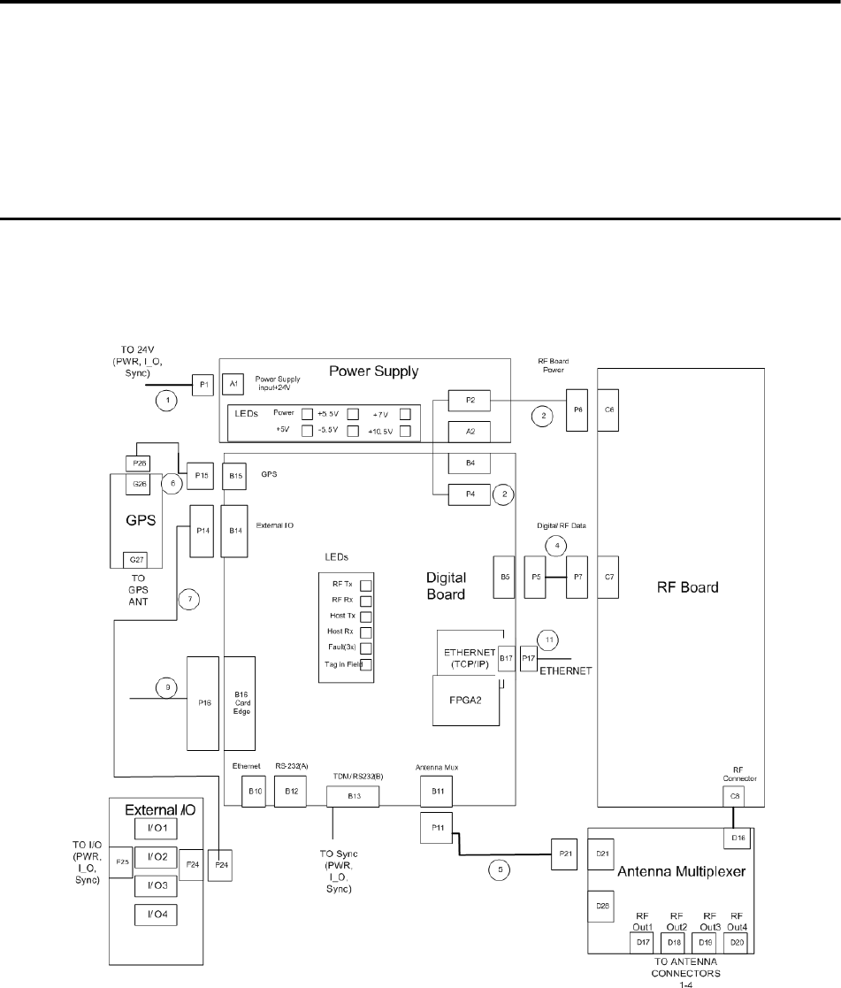
Hardware Interfaces
Use or disclosure of Proprietary Information contained on this sheet is subject to the restriction stated on the title page of this document. B-3
Appendix B
Hardware Interfaces
This appendix describes the physical interconnections within the
Orion® Reader.
Hardware Interfaces
This appendix describes the hardware interfaces in the Orion Reader and to external
components, such as antennas. Figure B-1 shows the basic hardware interconnec-
tions for the Orion Reader.
Figure B-1 Orion Reader Hardware Interconnection Block Diagram

Orion Reader System Guide
B-4 Use or disclosure of Proprietary Information contained on this sheet is subject to the restriction stated on the title page of this document.
Communications
The Orion Reader communicates with a host via an Ethernet communications proto-
col.
TCP/IP Fast Ethernet Connection
The Orion Reader communicates with a host via an Ethernet communications proto-
col. This connection requires an RJ–45 connector. If you connect the Orion Reader
directly to a host personal computer (PC) then you need a crossover cable. Star Sys-
tems recommends that you use Belden 7929A Category 5e twisted-pair cable for
Ethernet connections.
The Ethernet connector is an RJ-45 jack and uses a 100-base T interface. If the Orion
Reader is connected directly to the host system then a crossover cable is required.
Table B-1 lists the Ethernet connector pin assignments.
Table B-1 Ethernet Connector
Pin Signal Description 568Aa568Ba
1 TX+ Output Differential
Transmit Data (+) White w/ green stripe White w/ orange stripe
2 TX- Output Differential
Transmit Data (-) Green w/ white stripe or
solid green Orange w/ white stripe
or solid orange
3 RX+ Input Differential Receive
Data (+) White w/ orange stripe White w/ green stripe
4 Not connected N/A Blue w/ white stripe or
solid blue Blue w/ white stripe or
solid blue
5 Not connected N/A White w/ blue stripe White w/ blue stripe
6 RX- Input Differential Receive
Data (-) Orange w/ white stripe
or solid orange Green w/ white stripe or
solid green
7 Not connected N/A White w/ brown stripe
or solid brown White w/ brown stripe
8 Not connected N/A Brown w/ white stripe or
solid brown Brown w/ white stripe or
solid brown
a. 568A and 568B are Ethernet cable designations.
Hardware Interfaces
Use or disclosure of Proprietary Information contained on this sheet is subject to the restriction stated on the title page of this document. B-5
Sync/COM1 Port
This connector is an 8-pin block header receptacle. The signal descriptions are listed
in Table B-2.
External Digital Input/Output Connector
This connector is used for the digital input/output assembly, which is used to interface
the Orion Reader with external inputs and outputs. Inputs can be devices such as light
curtains or loops, and outputs can be devices such as gates or lights (connector is P/N
33357-01). The signal descriptions are listed in Table B-3.
Table B-3 Digital I/O Pin-outs on Power, Sync, and I/O Connector
Table B-2 RS-232B/sync Connector Parameters
Pin Signal Description DB-9 Socket
Connector
1 TXD Transmit Data 2
2 RXD Receive Data 3
3 DTR Data Terminal Ready (not connected) 4
4 RTS Request to Send 7
5 CTS Clear to Send 8
6 GND Ground 5
7 SYNC+ sync positive signal -
8 SYNC- sync negative signal -
Wire Pin No
Power +24V 5
Power +24V 6
Power Return 7
Power Return 8
Sync- 3
Sync+ 4
I/O 1 1

Orion Reader System Guide
B-6 Use or disclosure of Proprietary Information contained on this sheet is subject to the restriction stated on the title page of this document.
I/O 1 Return 15
I/O 2 14
I/O 2 Return 13
I/O 3 12
I/O 3 Return 11
I/O 4 10
I/O 4 Return 9
Wire Pin No

C
System Technical Specifications

System Technical Specifications
C-3
C
System Technical Specifications
This appendix provides reference specifications for the Orion® Reader
components.
Component Specifications
This appendix describes the engineering specifications for the reader components.
This appendix does not include specifications for reader options, those are described
in Appendix D, “Options.”
Orion Reader
The reader environmental specifications are listed in Table C-1.
Toll Antenna
A toll antenna should meet the specifications as follows:
•Operates in the location and monitoring service band (902 to 928 MHz).
•Optimum radiation pattern — Virtually no side or back lobes help to confine
antenna coverage to a single lane.
•Weatherproof — Each antenna is housed in a radome made of materials with
Table C-1 Orion Reader Environmental Specifications
Environment Specification
Shock 10 G, sawtooth pulse @11ms duration
Vibration 5-20 Hz: 0.1 inch; peak to peak
20-200 Hz: 2 G peak
Note No more than 2-dB tag-in-box sensitivity degradation
under the vibration conditions on all 3 axis
Temperature range Storage temperature range: –40C to +85C
Humidity 0% to 95% noncondensing over all temperatures.

Orion Reader System Guide
C-4 Use or disclosure of Proprietary Information contained on this sheet is subject to the restriction stated on the title page of this document.
favorable electrical characteristics and resistance to ultraviolet radiation.
•Bandpass filtering helps to attenuate interference from other RF sources.
Environmental Specifications
The toll antenna can withstand the environmental tolerances shown in Table C-2.
Table C-2 Antenna Environmental Tolerances
Environment Specification
Dust NEMA pub 250-1991, Sec. 6.5, page 18
Rain NEMA pub 250-1991, Sec. 6.4, page 17 and Sec. 6.7, page
19
Corrosion
resistance NEMA pub 250-1991, Sec. 6.9, page 20
Shock 5 G ½-sine pulse, 10 ms duration, 3 axes
Vibration 0.5 Grms 10-500 Hz
Temperature range -40F to +167F (-40Cto+75C)
Humidity 100% condensing

D
Orion Reader Options
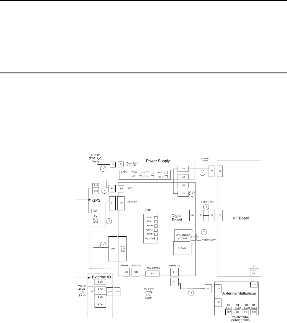
Orion Reader Options
Use or disclosure of Proprietary Information contained on this sheet is subject to the restriction stated on the title page of this document. D-3
Appendix D
Orion Reader Options
This appendix will describe each of the options available with the Orion®
Reader.
Orion Reader Options
This appendix describes the installation, operation, technical specifications, and pre-
ventive maintenance for the options available with the Orion Reader. Not all of the
options can be used on the same Orion Reader due to conflicts between the connec-
tors.
•“Digital Input/Output Modules”
•“Global Positioning System Timing Option”
Figure D-1 shows the optional assemblies.
Figure D-1 Connector Locations for External Options
Orion Reader System Guide
D-4 Use or disclosure of Proprietary Information contained on this sheet is subject to the restriction stated on the title page of this document.
Digital Input/Output Modules
The digital input/output (I/O) assembly is used to interface the Orion Reader with
external inputs and outputs. Inputs can be devices such as light curtains or loops, and
outputs can be devices such as gates or lights.
The digital I/O circuit board can accommodate up to four OPTO 22 G4-model input or
output modules and screw terminal connectors for connecting the Orion Reader to
external interfaces. These modules are optional.
Presence detectors (loop detectors, wheel detectors, infrared/laser lights) can be
installed through the input sense circuits to turn on the Orion Reader when an object is
detected approaching the reading range.
Output functions such as traffic lights, cameras, signs and gates may be controlled
through the reader’s status output circuits.
The output modules are controlled by 5V signals from the Orion Reader. The output
modules support voltages up to 100V DC or 130V AC on their output pins. The input
module outputs a 5V signal to the Orion Reader. The input modules recommended by
Star Systems use from 2.5V to 28V DC.
The OPTO 22 input/output modules are not supplied with the digital I/O assembly. Go
to www.opto22.com for a listing of input and output modules.
Caution
The Orion Reader digital I/O port is not surge protected, therefore Star Systems
strongly recommends that only OPTO 22 modules be used to configure any external
I/O device that will be controlled through the digital I/O port. DO NOT connect any
external device directly to the digital I/O port.
Damage to the Orion Reader caused by power surges or spikes linked to incorrect
use of the digital I/O port will void the reader warranty.
Required Components/Tools
Before installing the digital I/O assembly and modules, make sure you have the neces-
sary components.
•Digital I/O Kit ( P/N 77-6000-001). Here is a parts list for the kit:
•Phillips head screwdriver for installing the I/O assembly and modules to the Orion
Reader.
Quantity Description
1 Mounting rack for OPTO modules
4 #6-32 x 1/4 inch Phillips screw
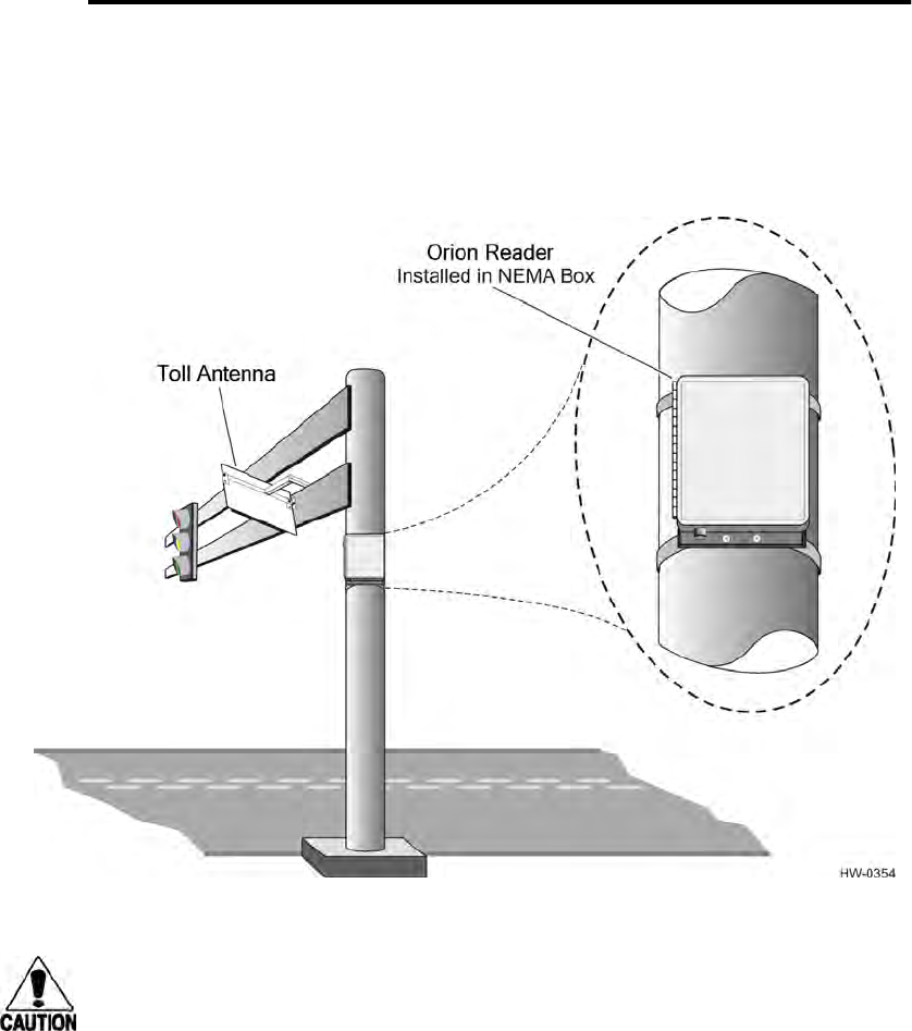
Orion Reader Options
Use or disclosure of Proprietary Information contained on this sheet is subject to the restriction stated on the title page of this document. D-5
•Assortment of 14-22 AWG wires to connect modules to mounting rack.
Installation/Mounting/Grounding of the Reader
Connect the stainless steel backplate used to mount the NEMA enclosure to earth
ground using a ground cable and stake. Follow the National Electric Code for light-
ning protection for the locale where you are installing the Orion Reader. Figure D-2
shows an example of a site installation using a NEMA enclosure.
Figure D-2 Sample NEMA Enclosure Installation
Caution
To protect the Orion Reader, attach the mounting plate to the ground cable. To
ensure that the mounting structure and NEMA enclosure housing the Orion Reader
are sufficiently grounded, have a licensed electrician certify the grounding system.
If you install the backplate on a mounting pole or other assembly that is sufficiently
grounded to earth, and all of the surfaces are good conductors, you may not need to
use a grounding cable.
Tighten the mounting hardware to 50 ft-lb (68 N/m) to ensure that the box will sustain
vibration requirements.
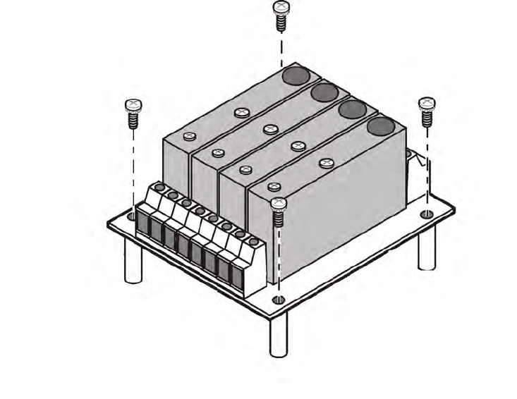
Orion Reader System Guide
D-6 Use or disclosure of Proprietary Information contained on this sheet is subject to the restriction stated on the title page of this document.
To Mount the Digital I/O Modules on the Orion Reader
1. Place the Digital I/O Module (Figure D-3) on the Orion Reader.
Figure D-3 Digital I/O Modules on Orion Reader
2. Insert I/O module(s) into assembly and tighten mounting screw at top of module.
Figure D-4 shows sample wiring schematic for digital I/O Input 1.
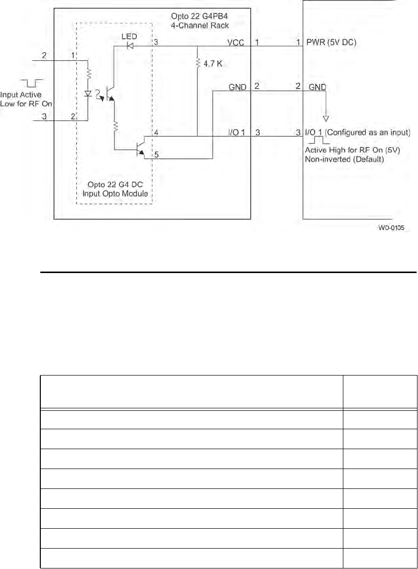
Orion Reader Options
Use or disclosure of Proprietary Information contained on this sheet is subject to the restriction stated on the title page of this document. D-7
Figure D-4 Example of Digital I/O Input 1
Testing the Digital I/O Components Using TCP
Commands
To test the digital I/O components using TCP commands, send the applicable TCP
commands listed in Table D-1.
Table D-1 Digital I/O Command Group Commands
Digital I/O Configuration Command Command
Code
Set Digital I/O Sensor Status Change Report 0000H
Get Digital I/O Sensor Status Change Report 0001H
Set Digital I/O Output Host Control 0002H
Get Digital I/O Output Host Control 0003H
Set Digital I/O Output Tag Read Control 0004H
Get Digital I/O Output Tag Read Control 0005H
Set Digital I/O RF Control 0006H
Get Digital I/O RF Control 0007H

Orion Reader System Guide
D-8 Use or disclosure of Proprietary Information contained on this sheet is subject to the restriction stated on the title page of this document.
Guidelines for Ordering the I/O Modules
The digital I/O assembly can accommodate up to four OPTO 22 G4-model input or
output modules for connecting the Orion Reader to external interfaces. Star Systems
recommends that the I/O modules have the following specifications:
Set Digital I/O RF Multiplexing Mode 0008H
Get Digital I/O RF Multiplexing Mode 0009H
Set Digital I/O Output Pulse Duration 000AH
Get Digital I/O Output Pulse Duration 000BH
Set Digital I/O Minimum Presence True Period 000CH
Get Digital I/O Minimum Presence True Period 000DH
Set Digital I/O Sensor Input Inversion 000EH
Get Digital I/O Sensor Input Inversion 000FH
Set Digital I/O Port Configuration 0010H
Get Digital I/O Port Configuration 0011H
Set Digital I/O Sensor Input Report 0012H
Get Digital I/O Sensor Input Report 0013H
Set Digital I/O Presence RF Control Algorithm 0014H
Get Digital I/O Presence RF Control Algorithm 0015H
Set Digital I/O Presence RF Control Time-Out Period 0016H
Get Digital I/O Presence RF Control Time-Out Period 0017H
Get Digital I/O Port Status 0018H
Set Digital I/O Mode 0019H
Get Digital I/O Mode 001AH
Set External Interrupt Control 056DH
Get External Interrupt Control 06ADH
Table D-1 Digital I/O Command Group Commands (continued)
Digital I/O Configuration Command Command
Code

Orion Reader Options
Use or disclosure of Proprietary Information contained on this sheet is subject to the restriction stated on the title page of this document. D-9
Input Module — input voltage from Orion Reader: 2.5V to 28V DC; output voltage
to Orion Reader: 5V DC logic
Output Module — input voltage from Orion Reader: 5V DC logic; output voltages of
up to 100V DC or 130V AC on their output pins.
Table D-2 lists the acceptable OPTO 22 input modules and Table D-3 lists the
acceptable OPTO 22 output modules to be used with the Orion Reader.
Table D-2 Acceptable Input Modules
OPTO 22 MODULE P/N INPUT VOLTAGE OUTPUT VOLTAGE
G4IAC5 90V-140V AC or DC 4.5V-6V DC
G4IAC5L 90V-140V AC or DC 4.5V-6V DC
G4IAC5MA 90V-140V AC or DC 4.5V-6V DC
G4IDC5 10V-32V DC or 12V-32V AC 4.5V-6V DC
G4IDC5B 4V-16V DC or AC 4.5V-6V DC
G4IDC5D 2.5V-28V DC 4.5V- 6V DC
G4IDC5K 2.5V-16V DC 4.5V-6V DC
G4IDC5MA 10V-32V DC or 12V-32V AC 4.5V-6V DC
G4IDC5-SW Dry contact 4.5V-6V DC
G4IDC5-SWNC Dry contact 4.5V-6V DC
Table D-3 Acceptable Output Modules
OPTO 22 MODULE P/N INPUT VOLTAGE OUTPUT VOLTAGE
G4OAC5 4V-8V DC 12-140V AC
G4OAC5FM 4V-8V DC 12-140V AC
G4OAC5MA 4V-8V DC 12-140V AC
G4ODC5 4V-8V DC 5V-60V DC
G4ODC5FM 4V-8V DC 5V-60V DC
G4ODC5MA 4V-8V DC 5V-60V DC
G4ODC5R 4.8V-6V DC 100V DC or 130V AC
G4ODC5RFM 4.8V-6V DC 100V DC or 130V AC
G4ODC5R5 4.8V-6V DC 100V DC or 130V AC
G4ODC5R5FM 4.8V-6V DC 100V DC or 130V AC
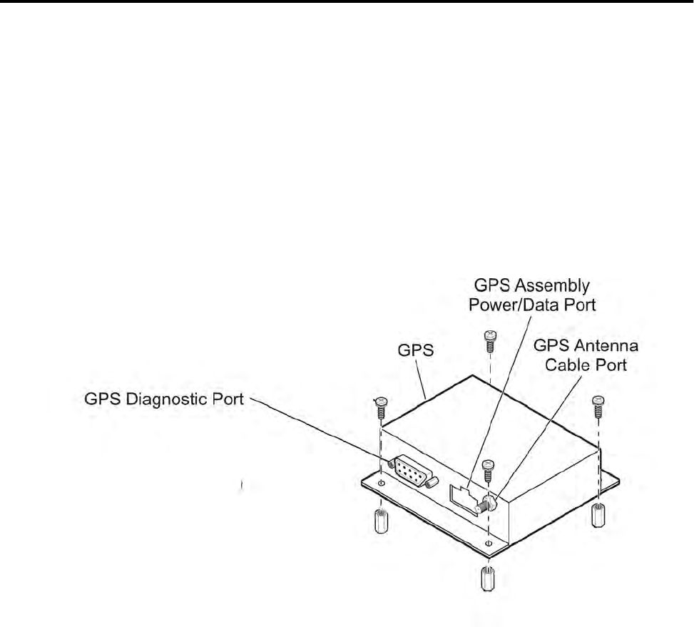
Orion Reader System Guide
D-10 Use or disclosure of Proprietary Information contained on this sheet is subject to the restriction stated on the title page of this document.
You can configure the I/O assembly with any combination of the four modules; for
instance, four inputs, four outputs, three inputs and one output, three outputs and one
input, and so on.
Global Positioning System Timing Option
The Global Positioning System (GPS) timing option available on Orion Readers per-
mits a GPS-equipped multiprotocol reader in one plaza to be synchronized with
another GPS-equipped multiprotocol reader in another location without being physi-
cally connected by a sync cable. This configuration is highly useful when physical
barriers or boundaries prevent a sync cable between plazas to be used. The GPS option
also can be used to synchronize any number of GPS-equipped multiprotocol readers
when no physical barrier is present.
The GPS timing assembly, which uses the globally available NAVSTAR GPS satel-
lite navigation and timing service, can provide a precise 1 pulse per second (PPS) tim-
ing signal to the Orion Reader. The GPS timing assembly mounts to the top of the
Orion Reader (Figure D-5).
Figure D-5 GPS Assembly
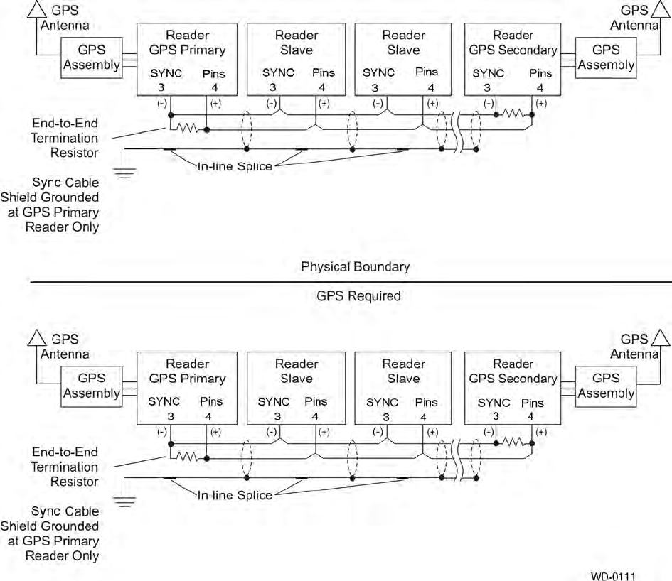
Orion Reader Options
Use or disclosure of Proprietary Information contained on this sheet is subject to the restriction stated on the title page of this document. D-11
This GPS timing option permits a GPS-equipped Orion Reader in one plaza to be syn-
chronized with another GPS-equipped Orion Reader in another plaza without being
physically connected by a Sync data cable (Figure D-6). This configuration is useful
when physical barriers or long distances prevent a Sync data cable between plazas to
be used.
Figure D-6 Sync Configuration Using GPS Timing Option
Star Systems recommends Belden 89182 (150 impedance), which is a single
twisted-pair shielded cable rated for outdoor use, or 8132 (120 impedance), which
is a double twisted-pair shielded cable that must be installed in conduit. The Belden
8132 cable has an extra pair that is not used. Using these low-loss, low-capacitance
twisted-pair cable, a distance of 1000 feet (305 m) has been obtained. This maximum
distance may be slightly longer or shorter depending on the cable type used.
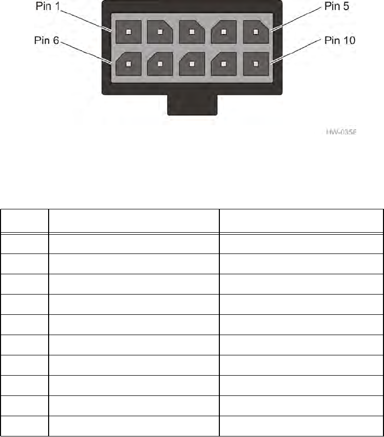
Orion Reader System Guide
D-12 Use or disclosure of Proprietary Information contained on this sheet is subject to the restriction stated on the title page of this document.
Star Systems recommends using the cable shielding and grounding scheme shown in
Figure D-7 to reduce the risk of electromagnetic interference disrupting or damaging
the Sync circuitry in the Orion Reader.
GPS Power and Data Connector
Figure D-7 shows the power and data connector and Table D-4 lists the connector pin
assignments and descriptions.
Figure D-7 GPS Assembly Power/Data Connector
Table D-4
GPS Assembly Connector Pin Assignments and Signal Descriptions
Pin Signal Description
1 TXD1 Transmit data (3V logic)
2 RXD1 Receive commands (3V logic)
3 Not connected N/A
4 1 PPS 1 pulse-per-second output
5 Ground Signal and power common
6 Not connected N/A
7 Not connected N/A
8 Not connected N/A
9 GPS receiver and antenna power +5V
10 Not connected N/A

Orion Reader Options
Use or disclosure of Proprietary Information contained on this sheet is subject to the restriction stated on the title page of this document. D-13
The GPS antenna mounts outside the plaza structure (Figure D-8). The antenna con-
nects to the GPS assembly with a coaxial cable.
Figure D-8 Example of GPS Used to Connect Separate Parking Sites
Before Installing the GPS Antenna
Before installing the GPS for the toll plaza, you need to ensure that the antenna will be
visible to GPS satellites. You should choose an antenna location that has clear, 360-
degree visibility to the sky.
Once you are sure that the antenna reception will be unobstructed, you can begin installing
the antenna. Make sure you have the following Star Systems-supplied items:
GPS kit ( P/N 23-5000-001 or 23-6000-001) consists of the items listed in Table D-5:
Table D-5 Global Positioning System Accessory Kit Contents
Quantity Description
1 Global positioning system assembly
1 Active GPS antenna
1 GPS power/data cable
4 #6-32 x 3/8 inch stand-off
4 #6-32 x 1/4 inch Phillips screw

Orion Reader System Guide
D-14 Use or disclosure of Proprietary Information contained on this sheet is subject to the restriction stated on the title page of this document.
Required Components/Tools
Once you are sure that the antenna reception will be unobstructed, you can begin
installing the antenna. Make sure you have the following -supplied items:
•GPS timing accessory kit (GPS assembly, power/data cable, antenna, and mount-
ing hardware, P/N 19100-02)
You need the following additional equipment and tools to complete the installation:
•Fifty-ohm antenna coaxial cable with attenuation loss of less than 12 dB @1.575
GHz.
Note: Maximum cable length is determined by cable attenuation loss. Installer should
calculate the cable loss for the specific cable being used.
•Pole/pipe mounting hardware (e.g., anchor bolts)
•Length of 1 1/4-inch (3.175 cm) Schedule 40 pipe (stainless steel, aluminum, or
galvanized steel) to be used for antenna pole
•Cable terminating/crimping tools
•Torque-limiting wrench (in-lb range)
•Standard set of tools (screwdrivers, pliers, wrenches) for fastening the GPS
assembly to the Orion Reader.
•Special tools for installing the GPS antenna at site, for example, impact hammer
for drilling into concrete, if needed.
You can order additional GPS antennas (P/N 20015-01) from Star Systems.
GPS Timing Assembly Mounting
1. Screw the four standoffs into the mounting holes of the Orion Reader as shown in
Figure D-5.
2. Place the GPS assembly on the standoffs and secure with the Phillips screws
provided in the kit.
Caution
Tighten the standoffs and mounting screws until snug. Do not overtighten.
3. Connect the GPS assembly to the reader with the power/data cable provided in
the GPS assembly kit.
GPS Antenna Mounting
Orion Reader Options
Use or disclosure of Proprietary Information contained on this sheet is subject to the restriction stated on the title page of this document. D-15
Note: The GPS antenna installation must comply with applicable structural and
building codes for the locale where it is being installed.
1. Select a location for the GPS antenna that provides maximum visibility to the
sky.
2. Secure the antenna pole mounting hardware to the site structure.
3. Connect the antenna pole to the mounting hardware.
4. Insert the RF coaxial cable up through the inside of the mounting pipe and
connect the cable to the antenna using a Type-N plug connector.
Refer to Figure D-9 when assembling the antenna components.
You also can cut a 1-inch (2.54-cm) wide by 2-inch (5.1-cm) long slot in the side
of the mounting pipe (Figure D-9). Star Systems recommends this procedure for
installing the RF coaxial cable when it cannot be pulled through the bottom of the
pipe.
5. Pull the cable up through the pipe bottom or slot and terminate it at the antenna
port.
Note: If you choose to use a different mounting pole material than the 1-¼ inch
(3.175 cm) Schedule 40 pipe, the pole material should have a nominal outside diame-
ter of 1.66 inches (4.2 cm). Proper material selection for the field installation is left to
the system installers.
6. Slip the antenna mount over the coaxial cable.
7. Screw the Type-N plug connector onto the type-N antenna receptacle connector
and tighten until snug.
8. Connect the mount to the antenna by tightening the four captive screws until
snug.
9. Push the antenna-mount assembly onto the antenna pipe or pole and tighten the
hex-head set screws on the antenna mount.
10. Connect the antenna to the Orion Reader at the GPS antenna cable port (Figure
D-5). Tighten this SMA connector to 10 in-lb.
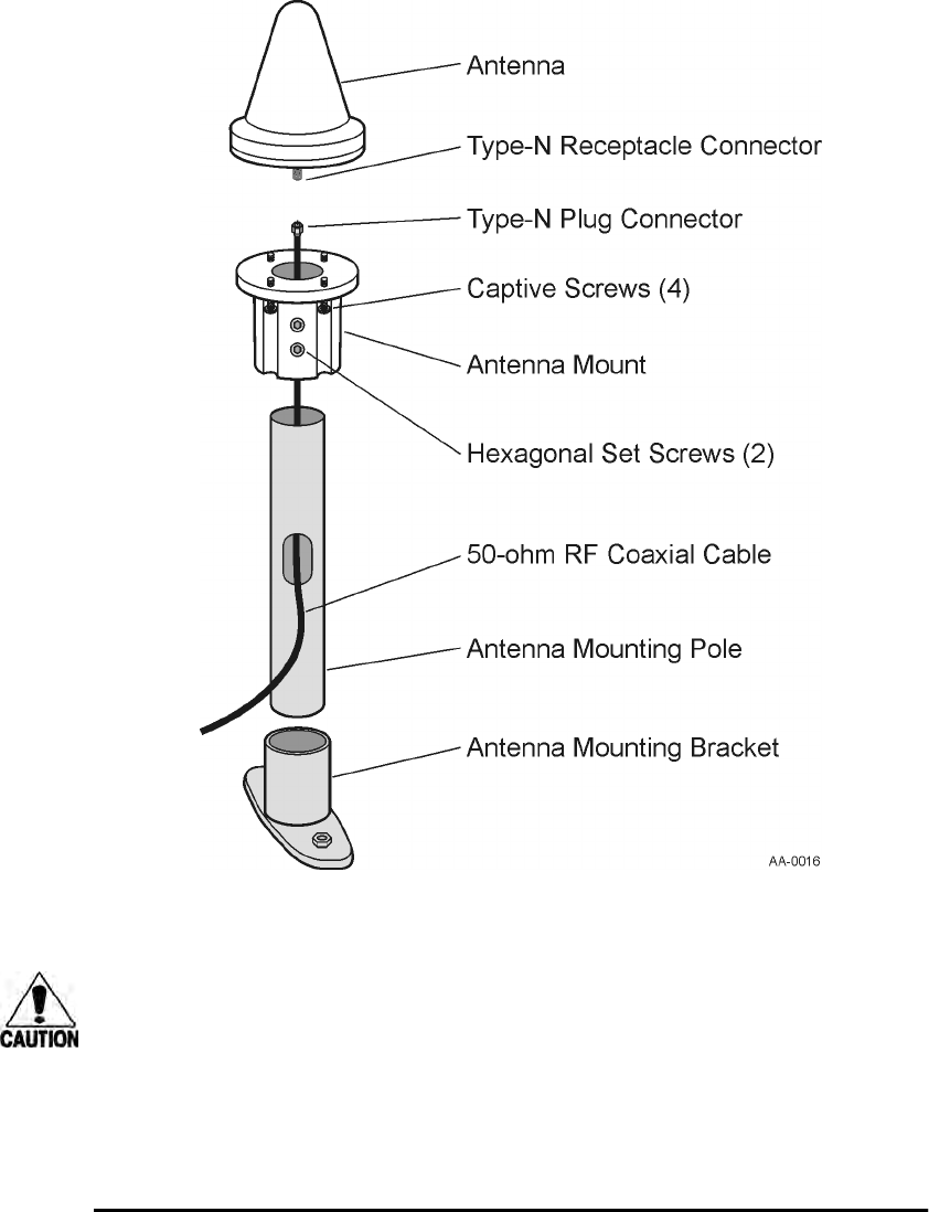
Orion Reader System Guide
D-16 Use or disclosure of Proprietary Information contained on this sheet is subject to the restriction stated on the title page of this document.
.
Figure D-9 GPS Antenna Assembly
Caution
To prevent damage to the SMA connector, Star Systems strongly recommends that
you provide a strain-relief bracket or other means of securing the GPS antenna
coaxial cable that terminates at the GPS timing assembly.
Note: The antenna mount must be grounded in accordance with National Electrical Code
regulations for the locale where the Orion Reader/GPS antenna system is being installed.
Testing the GPS Timing System
The following sections list basic command information for testing using TCP.
Orion Reader Options
Use or disclosure of Proprietary Information contained on this sheet is subject to the restriction stated on the title page of this document. D-17
Note: As the GPS system activates, the Sync error LED lights on the Orion Reader.
This error indication usually clears in about 1 minute, but it can take as long as 15
minutes.
Using the TCP Command Set
Configure and test the GPS timing option using the TCP command set by sending the
appropriate TCP command (“Set Master/Slave Mode” on page 6-109).
Configuring the Reader/Slave Count
This section explains how to configure the reader/slave hierarchy (GPS primary/GPS
secondary or master/slave) using the GPS TCP command.
Choose one field only, for example, GPS primary, GPS secondary, master, or slave.
GPS Primary — This field specifies whether the reader is to be configured as the
GPS primary.
GPS Secondary — This field specifies whether the reader is to be configured as the
GPS secondary.
GPS Primary Definition
0 Not GPS Primary
1 GPS Primary
GPS Secondary Definition
0 Not GPS Secondary
1 GPS Secondary

Orion Reader System Guide
D-18 Use or disclosure of Proprietary Information contained on this sheet is subject to the restriction stated on the title page of this document.
Master — This field specifies whether the reader is to be configured as the master.
Slave — This field specifies whether the reader is to be configured as the slave.
For this example, the sum of the delay and duration period is 19.9 milliseconds, which
is less than the synchronization rate of 20 milliseconds. If the sum of the delay and
duration periods equals the synchronization rate, unexpected results can occur.
Slave Select Count — This field specifies the order that a slave or GPS primary or
secondary reader issues a synchronization pulse whenever a given reader within a syn-
chronization group fails to recognize the signal from the preassigned master or when-
ever a GPS receiver fails to issue a 1-pps signal, respectively. The maximum slave
count = 26.
Scenario 1 — One master, n slaves. The master has no slave behavior, therefore it is
assigned a slave select count of 0. Each slave is assigned an increasingly greater num-
ber from 1 to n. When the master fails, slave 1 becomes the master, and so on.
Scenario 2 — GPS primary, GPS secondary, N slave readers. When in fault mode (1-
pps signal missing), a GPS primary is slave to a GPS secondary and all other slaves
and is assigned the last slave select count, n. A GPS secondary takes over when a GPS
primary is in fault mode, therefore it is assigned a slave select count of 1. All slaves
are assigned increasingly greater numbers from 2 to n+1.
Scenario 3 — One GPS primary and n slaves. This scenario forces the GPS primary
to have no slave behavior by specifying a slave select count of 0. Each slave is an
increasingly higher number from 1 to n. When the master fails, slave 1 becomes the
master. If slave 1 should fail, slave 2 takes over, and so on (Table D-6).
Master Definition
0 Not Master
1 Master
Slave Definition
0 Not Slave
1 Slave
Table D-6 Reader Slave Count ConfigurationTable
Scenario 1 —One Master, n Slaves
Reader Mode Master Slave Slave Slave Slave Slave
Slave Select Count 0 1 2 … n-1 n
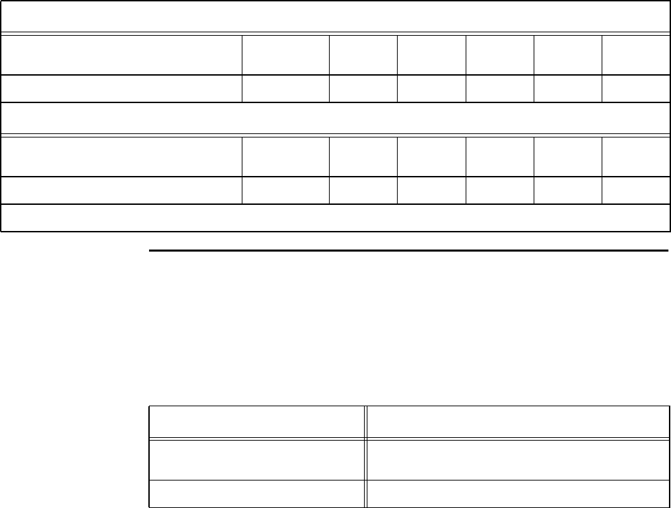
Orion Reader Options
Use or disclosure of Proprietary Information contained on this sheet is subject to the restriction stated on the title page of this document. D-19
Environmental
Temperature Range for GPS Assembly
The GPS assembly can operate within the following operating and storage tempera-
ture conditions (Table D-7).
Humidity
The Orion Reader GPS assembly is rated to operate within humidity levels of 0% to
95%, non-condensing.
Scenario 2 —GPS Primary, GPS Secondary, n Slaves
Reader Mode GPS
Secondary Slave Slave Slave Slave GPS
Primary
Slave Select Count 1 2 3 … n+1 n+2
Scenario 3 —One GPS Primary, n Slaves
Reader Mode GPS
Primary Slave Slave Slave Slave Slave
Slave Select Count 0 1 2 … n-1 n
n = Total number of slave readers
Table D-6 Reader Slave Count ConfigurationTable (continued)
Table D-7 Operating/Storage Temperature Limits and Conditions
Specification Limits/Conditions
Operating temperature installed
in NEMA -40°F to +131°F (-40°Cto+55°C)
Storage temperature range -40F to +185F (-40Cto+85C)

Orion Reader System Guide
D-20 Use or disclosure of Proprietary Information contained on this sheet is subject to the restriction stated on the title page of this document.
GPS Antenna
Table D-8 lists the GPS antenna specifications.
GPS Assembly Connector
GPS Diagnostic Port
The GPS diagnostic port is used for factory diagnostics only.
GPS Antenna Cable
The antenna connects to the GPS assembly via an RF coaxial cable that is supplied by
the Orion Reader user. The GPS antenna cable connects the receiver to the assembly’s
end panel and is externally available.
For applications requiring lightning protection on the GPS assembly/antenna system,
the lightning arrestor must be able to pass DC voltage or current on the center conduc-
tor of the coaxial cable. The GPS assembly transmits a DC bias voltage and current
through the center conductor from to the antenna to power the low-noise amplifier,
which is integrated into the active GPS antenna. Using a DC-block lightning protec-
tion system will not work. Star Systems recommends you use a gas-discharge-type
system designed for an active GPS antenna.
Regulatory Requirements
Emissions
The GPS assembly complies with the requirements of FCC Part 90, FCC Part 15, and
industry Canada RSS-137 (where applicable).
Safety
The GPS assembly is UL60950 approved.
Table D-8 GPS Antenna Specifications
Parameter Specification
Operating temperature -40°F to +185°F (-40°Cto+85°C)
Operating frequency 1527.42 ±1.023 MHz, typical
Power supply 5V DC
Current 27 mA maximum
Polarization RT hand circular
Output VSWR 2.5 maximum
Gain 30 dB minimum

Orion Reader Options
Use or disclosure of Proprietary Information contained on this sheet is subject to the restriction stated on the title page of this document. D-21
Electrical Protection
ESD
With the GPS assembly installed and operated as part of a complete Orion chassis
assembly, the assembly complies with the requirements of the International Electro-
technical Commission/Comite, Europe, en de Normalisation (IEC/EN) 61000-4-2,
Class 4 standard (Table D-9).
Antenna Drive and Protection Circuitry
The receiver uses an antenna sense circuit that detects under-current (open), over-cur-
rent (shorted or exceeding maximum), or valid antenna connection. The receiver sup-
plies up to 80 milliamps (mA) of current via the antenna power supply circuit.
If the antenna draws 15 mA or more, a status bit in the antenna status information is
set, giving a good indication that an antenna is attached.
If the antenna draws less than 15 mA, an alarm bit is set indicating an under-current
condition in the antenna status information.
If more then 80 mA is drawn through the antenna port, then the over-current detection
circuitry will reduce the antenna feed current to approximately 45 mA until the fault is
cleared.
Detection of an under-current situation will not prevent the receiver from operating.
The receiver will continue to operate normally, but will issue an error flag indicating a
possible antenna problem.
Antenna Drive Current Limits
Undercurrent detect @+77oF (25oC)
Good Indication: greater than 15 mA
Undercurrent Indication: less than 15 mA
Over-current Detect @+77oF (25oC): 80 mA maximum for normal operation
Table D-9 ESD Limits and Conditions
Discharge Voltage 16.0 kV
Polarity Positive
Number of Repetitions 2 pulses
ESD System NSG438 system, which complies with a 150-picofarad/330-ohm
discharge network of the IEC/EN 61000-4-2 standard
Test conditions All ESD tests are performed at +77F (+25C)
Orion Reader System Guide
D-22 Use or disclosure of Proprietary Information contained on this sheet is subject to the restriction stated on the title page of this document.
Troubleshooting the GPS System
Note: See “Communicating Via Diagnostic Port (COM2)” on page 10-4 to learn how
to access system diagnostics fault messages.
When the GPS receiver initializes, it performs a self-test, which includes a check of
the GPS antenna status. If a fault condition exists, the message displays GPS Self Test
Fault = 1, which means that an error condition exists with either the GPS receiver or
coaxial antenna cable. You can display the fault status by entering a ShowSysStatus-
Bits command from a PC.
If a fault condition exists, first check the GPS coaxial cable and connections. After
checking the cable, if the fault condition remains, switch the cable with another, good,
cable. If the fault condition continues, return the GPS assembly to Star Systems.
If the GPS self-test reveals no faults, the status bit displays GPS Self Test Fault = 0.
No further action is required.

E
Command-Based Pre- and Post-
Conditions

Command-Based Pre- and Post-Conditions
Use or disclosure of Proprietary Information contained on this sheet is subject to the restriction stated on the title page of this document. E-3
Appendix E
Command-Based Pre- and Post-Conditions
This appendix lists pre- and post-conditions for transmission control
protocol (TCP). In these tables, Stop Mode Required indicates that the
reader first must be set to Stop Mode (Mode 0) as a pre-condition to
entering the specified command. The post-conditions, Immediate or
Reset Required, indicate that the command either takes effect
immediately or that the reader must be reset after the command has
been entered. This is a subset of the complete list of commands and
lists only those commands that are needed to configure an Orion
Reader.
TCP Command Pre- and Post-Conditions
Table E-1 lists the TCP command pre- and post-conditions.
Table E-1 Pre- and Post-Conditions for TCP Commands
TCP Command
Group Command # Command Stop Mode Required/
Immediate/Reset Required
0x0200 - Diagnostics
0x0005 Clear Error Logs Immediate
0x0400 - Mode 0x0001 Set Mode Immediate if
1) TCP host startup selected
and mode and has not been
set previously;
2) Stop Mode is requested; or
3) Mode has been set
previously, Stop Mode is
current mode, and requested
mode is same as previous
operational mode.
Reset Required if
1) TCP non-volatile memory
startup selected and
requested mode is not Stop
Mode; or
2) requested mode is different
from previous operational
mode.

Orion Reader System Guide
E-4 Use or disclosure of Proprietary Information contained on this sheet is subject to the restriction stated on the title page of this document.
0x0400 - Mode 0x0003 Set Protocol Reset Required
0x0400 - Mode 0x0043 Set Tag Command Data Immediate if
1) Protocol is CVISN.
Stop Mode Required if
1) Request is not host driven.
Reset Required if
1) Command Action is 0.
0x0400 - Mode 0x0066 Set Seen Count Immediate
0x1000 - Tag 0x0002 Set Append Data Immediate
0x1000 - Tag 0x0025 Run CRC Immediate
0x1000 - Tag 0x002A Set Manual Antenna Channel
Control Immediate
0x1000 - Tag 0x0030 Set IAG Slot Reset Required
0x1000 - Tag 0x0040 Set Secondary Tag Sequence Reset Required
0x1000 - Tag 0x0045 Set Master/Slave Mode Immediate
0x2000 - RF 0x51 Set Attenuation Immediate
0x2000 - RF 0x53 Set Data Detect Immediate
0x2000 - RF 0x55 Set Line Loss Immediate
0x2000 - RF 0x57 Set Uplink Source Control Immediate
0x2000 - RF 0x60 Set Frequency in MHz Stop Mode Required
0x4000 - Digital I/O 0x0000 Set Sensor Status Change Report Immediate
Table E-1 Pre- and Post-Conditions for TCP Commands (continued)
TCP Command
Group Command # Command Stop Mode Required/
Immediate/Reset Required

Command-Based Pre- and Post-Conditions
Use or disclosure of Proprietary Information contained on this sheet is subject to the restriction stated on the title page of this document. E-5
0x4000 - Digital I/O 0x0002 Set Output Host Control Immediate if output host
control is enabled (i.e., both
predefined output control and
output by channel are
disabled)
Reset Required if output host
control is disabled (i.e., either
predefined output control or
output by channel is disabled)
0x4000 - Digital I/O 0x0004 Set Output Tag Read Control Reset Required
0x4000 - Digital I/O 0x0006 Set RF Control Reset Required
0x4000 - Digital I/O 0x0008 Set RF Multiplexing Mode Reset Required
0x4000 - Digital I/O 0x000A Set Output Pulse Duration Stop Mode Required
0x4000 - Digital I/O 0x000C Set Minimum Presence True
Period Stop Mode Required
0x4000 - Digital I/O 0x000E Set Sensor Input Inversion Stop Mode Required
0x4000 - Digital I/O 0x0010 Set Port Configuration Reset Required
0x4000 - Digital I/O 0x0012 Set Sensor Input Report Immediate
0x4000 - Digital I/O 0x0014 Set Presence RF Control
Algorithm Stop Mode Required
0x4000 - Digital I/O 0x0016 Set Presence RF Control Time-out
Period Stop Mode Required
0x4000 - Digital I/O 0x056D Set External Interrupt Control Reset Required (may only be
set if TCP Host Startup is
configured, and must be set
prior to setting mode. Reset is
required to change
parameters.)
0x8000 - System 0x0003 Set Time and Date Immediate
0x8000 - System 0x0009 Delete All Buffered Tag
Transactions Immediate
0x8000 - System 0x0011 Set TCP/IP Core Lane Controller
Parameters Reset Required
0x8000 - System 0x0013 Set TCP/IP Core IP Address Immediate
Table E-1 Pre- and Post-Conditions for TCP Commands (continued)
TCP Command
Group Command # Command Stop Mode Required/
Immediate/Reset Required

Orion Reader System Guide
E-6 Use or disclosure of Proprietary Information contained on this sheet is subject to the restriction stated on the title page of this document.
0x8000 - System 0x0016 Set Buffered Tag Transaction
Mode Immediate
0x8000 - System 0x0018 Set Data Acknowledge Time-out
Period Immediate
0x8000 - System 0x001A Set Switch Buffered Tag
Transaction Mode Enable Immediate
0x8000 - System 0x001F Get System Serial Number Immediate
Table E-1 Pre- and Post-Conditions for TCP Commands (continued)
TCP Command
Group Command # Command Stop Mode Required/
Immediate/Reset Required
I-1 Use or disclosure of Proprietary Information contained on this sheet is subject to the restriction listed on the title page of this document.
C
COM 1 properties dialog box, 9-7
Command group 9
reader system configuration
#984NYY SET TDM AS MASTER OR SLAVE, 1-17
Command-based pre- and post-conditions, AI1200-emulation, 1-
6
Command-based pre- and post-conditions, UDP, 1-3
Communicating via COM2 port, 9-4
Communicating via diagnostic port (COM2), 9-4
Communications
TCP/IP Fast Ethernet connection, 5-3
TCP/IP Fast Ethernet protocol
5-4
TCP/IP Fast Ethernet protocol message fields, 5-4
Component specifications
Orion Reader, 1-3
Toll Antenna 1-3
Toll Antenna, 1-3
Components
Toll antenna environmental specifications, 1-4
Components checklist 2-4
optional equipment, 2-4
Configuring a lane
marking read zone 8-3
guidelines, 8-4
required supplies, 8-4
purpose, 8-3
Configuring and operating
chapter organization, 6-3
tag transaction configuration group commands
set time-division parameters
secondary or slave select count
scenario 1, 6-111, 1-18
scenario 2, 6-111, 1-18
scenario 3, 6-111, 1-18
secondary or slave select count, 6-111, 1-18
TCP commands
diagnostic command group commands (0200H)
6-127
clear error logs, 6-139
get diagnostic interface status, 6-138
get diagnostic status, 6-133
get error log, 6-138
get number of error logs, 6-139
response data, 6-129
responses, 6-127
unsolicited diagnostic status reports, 6-133
digital I/O command responses, 6-38
digital I/O group commands (4000H)
6-37
digital I/O asynchronous reports
sensor input report, 6-45
sensor status change report, 6-43
digital I/O asynchronous reports, 6-43
get digital I/O minimum presence true period, 6-61
get digital I/O mode, 6-73
get digital I/O output host control, 6-51
get digital I/O output pulse duration, 6-58
get digital I/O output tag read control, 6-52
get digital I/O port configuration, 6-64
get digital I/O port status, 6-71
get digital I/O presence RF control algorithm, 6-67
get digital I/O presence RF control time-out period, 6-
70
get digital I/O RF control, 6-55
get digital I/O RF multiplexing mode, 6-56
get digital I/O sensor input inversion, 6-63
get digital I/O sensor input report, 6-66
get digital I/O sensor status change report, 6-47
get external interrupt control, 6-76
set digital I/O minimum presence true period, 6-60
set digital I/O mode, 6-73
set digital I/O output host control, 6-48
set digital I/O output pulse duration, 6-57
set digital I/O output tag read control, 6-52
set digital I/O port configuration, 6-63
set digital I/O presence RF control algorithm, 6-66
set digital I/O presence RF control time-out period, 6-
69
set digital I/O RF control, 6-53
set digital I/O RF multiplexing mode, 6-55
set digital I/O sensor input inversion, 6-62
set digital I/O sensor input report, 6-66
set digital I/O sensor status change report, 6-46
set external interrupt control, 6-74
mode command group commands (0400H)
6-114
get mode, 6-122
get protocol, 6-124
get seen count, 6-125
response data, 6-118
responses, 6-115
set mode, 6-121
set protocol, 6-123
set seen count, 6-124
RF transceiver group commands (2000H)
6-77
get data detect, 6-86
get frequency in MHz, 6-93
get line loss, 6-88
get RF attenuation, 6-84
get uplink source control, 6-89
RF transceiver command group response data, 6-80
RF transceiver command group responses, 6-78
set data detect, 6-85
set frequency in MHz, 6-90
set line loss, 6-87
set RF attenuation, 6-83
set uplink source control, 6-88
Orion Reader System Guide
I-2
system command bit definitions, 6-9
system command response bit definitions, 6-11
system command responses, 6-10
system commands, 6-6
system interface command responses, 6-14
system interface commands, 6-13
system interface group commands (8000H)
boot firmware download, 6-32
CPU firmware download, 6-23
delete all buffered tag transactions, 6-26
FPGA firmware download, 6-32
get buffered tag transaction mode, 6-28
get buffered tag transaction, 6-24
get data acknowledge time-out period, 6-29
get firmware version numbers, 6-33
get lane controller interface status, 6-27
get number of buffered tag transactions, 6-25
get switch buffered tag transaction mode enable, 6-30
get system interface status, 6-27
get system serial number, 6-32
get system startup status, 6-26
get time and date, 6-23
load default operating parameters, 6-33
reset reader, 6-24
set buffered tag transaction mode, 6-27
set data acknowledge time-out period, 6-28
set switch buffered tag transaction mode enable, 6-30
set time and date, 6-22
system identify, 6-21
tag transaction configuration group commands (1000H)
6-95
formats for time and date, 6-102
get asynchronous response append data, 6-102
get IAG slot, 6-106
get manual antenna channel control, 6-104
get master/slave mode, 6-112
get secondary tag sequence, 6-108
get SeGo table version number, 6-104
get synchronization timing parameters, 6-114
response data, 6-98
responses, 6-96
run check tag, 6-104
set asynchronous response append data, 6-101
set IAG slot, 6-105
set manual antenna control, 6-104
set master/slave mode, 6-109
set secondary tag sequence, 6-107
connection description dialog box, 9-6
Cross-lane interference
sync 3-7
Sync configuration example, 3-8
D
diagnostic COM2 port
pin assignments, 9-5
diagnostic commands
9-8
bootChange details, 9-10
bootChange, 9-8
check tag operation
AI1200-emulation
9-28
ClearErrorLog, 9-9
error log reference
9-13
diagnostic module, 9-26
digital I/O module, 9-28
GPS module, 9-20
lane controller interface module, 9-15
mode interface module, 9-18
RF transceiver module, 9-21
software module numbers, 9-13
system initialization module, 9-15
system interface module, 9-17
tag buffer module, 9-27
tag interface module, 9-18
ShowErrorLog, 9-9
ShowSysStatusBits, 9-9
version, 9-8
E
Error log reference, 9-13
F
Formulating site plan, 2-3
G
global positioning system timing
before you install, 1-13
connector pin-outs, 1-12
GPS antenna mounting, 1-13
power and data connector, 1-12
GPS antenna assembly
mounting, 1-14
GPS timing assembly
mounting, 1-14
GPS timing assembly, 1-10
Guide purpose, 1-3
Guide topics, 1-3
H
Hardware interfaces
antenna multiplexer/CRC connector, 1-5
digital I/O connector, 1-5
external digital input/output connector, 1-5
TDM/COM1 port, 1-5
Hardware replacement instructions
9-30
transmit/receive antenna on traditional gantry, 9-31
Health limits, 1-4
I-3 Use or disclosure of Proprietary Information contained on this sheet is subject to the restriction listed on the title page of this document.
Hyper Terminal main screen, 9-8
I
installation
3-11
Installation instructions
3-12
Intended audience, 1-3
L
Lane configuration
examples, 8-5
parameters for Title 21/SeGo protocols, 8-6
O
Operating the reader in Mode 88, 6-4
Orion Reader Options
see also GPS timing, 1-3
Orion Reader options
antenna multiplexer
preventive maintenance, 1-4
digital I/O assembly 1-4
digital I/O modules
ordering guidelines, 1-8
digital input/output assembly 1-4
testing with UDP commands, 1-7
digital input/output assembly, 1-3
global positioning system timing
1-10
global positioning system timing, 1-3
GPS timing assembly
environmental specifications, 1-19
testing with UDP commands, 1-16
NEMA 4X enclosure
installation
installation/mounting, 1-5
NEMA 4X enclosure, 1-3
see also digital I/O assembly, 1-3
P
Performing geographic RF site survey, 2-3
phone number dialog box, 9-6
Preparing the installation site
site preparation checklist, 2-3
Preventive maintenance schedule
9-29, 9-33
quarterly, 9-33
semiannually, 9-33
weekly, 9-33
R
Reader components
installation
Connecting Reader to Host System
full duplex operation, 3-9
network interface card, 3-9
NIC, 3-9
point-to-point, 3-9
Reader features
external device connectors
AC power supply, 3-6
COM1 connector, 3-9
diagnostic communications connector, 3-10
diagnostic test port connector, 3-11
digital I/O connector, 3-8
digital input/output connector, 3-8
Ethernet connector, 3-9
global positioning system connector, 3-11
GPS connector, 3-11
power supply specifics, 3-4
RS-232B/Sync connector, 3-9
selecting a power supply, 3-5
Sync connector, 3-9
sync connector, 3-9
external device connectors, 3-4
Reader features, 3-4
Reader features,external device connectors
RF antenna connectors, 3-7
Reader protocols
IAG, 3-3
see also Inter-Agency Group, 3-3
Title 21, 3-3
Reader system components, 3-3
Reader System installation
global positioning system, 2-4
mounting the components
cantilever arm mount, 2-7
open road tolling gantry mount, 2-8
overhead gantry mount, 2-5
overpass mount, 2-6
Removal/replacement procedures
antenna cable, 9-34
transmit/receive antenna, 9-33
removal/replacement procedures
9-33
S
Software information
Data acknowledge controls, 4-7
Orion Reader TCP 4-3
Orion Reader TCP messages
asynchronous response, 4-3
Orion Reader TCP messages, 4-3
TCP sequence number controls, 4-4
Starting terminal emulation software, 9-5
Starting the reader, 3-14
Sync configuration
cable grounding, 1-12
cable shielding, 1-12
optimum signal fidelity, 1-12
Orion Reader System Guide
I-4
System diagnostics
error indicators, 9-3
power cycling the Orion reader, 9-11
troubleshooting guidelines, 9-3
T
task checklist, 2-4
TCP tag responses
7-3
IAG cross-lane read response 7-13
example, 7-14
read response, Title 21
fields, 7-4
read response, Title 21, 7-4
SeGo streamlined read, 7-3
tag command fields, 7-3
TCP/IP Fast Ethernet protocol
messages
asynchronous response, 5-5
command request, 5-4
command response, 5-5
data acknowledge, 5-5
unsolicited status, 5-5
technical support 9-34
Toll Antenna, 1-3
Typographical conventions, 1-5
U
US FCC license statement, 1-2
V
Visual inspection, 9-29
W
Warning
minimum safe distance for maintenance personnel, 1-4
Working with Mode 88, 6-4