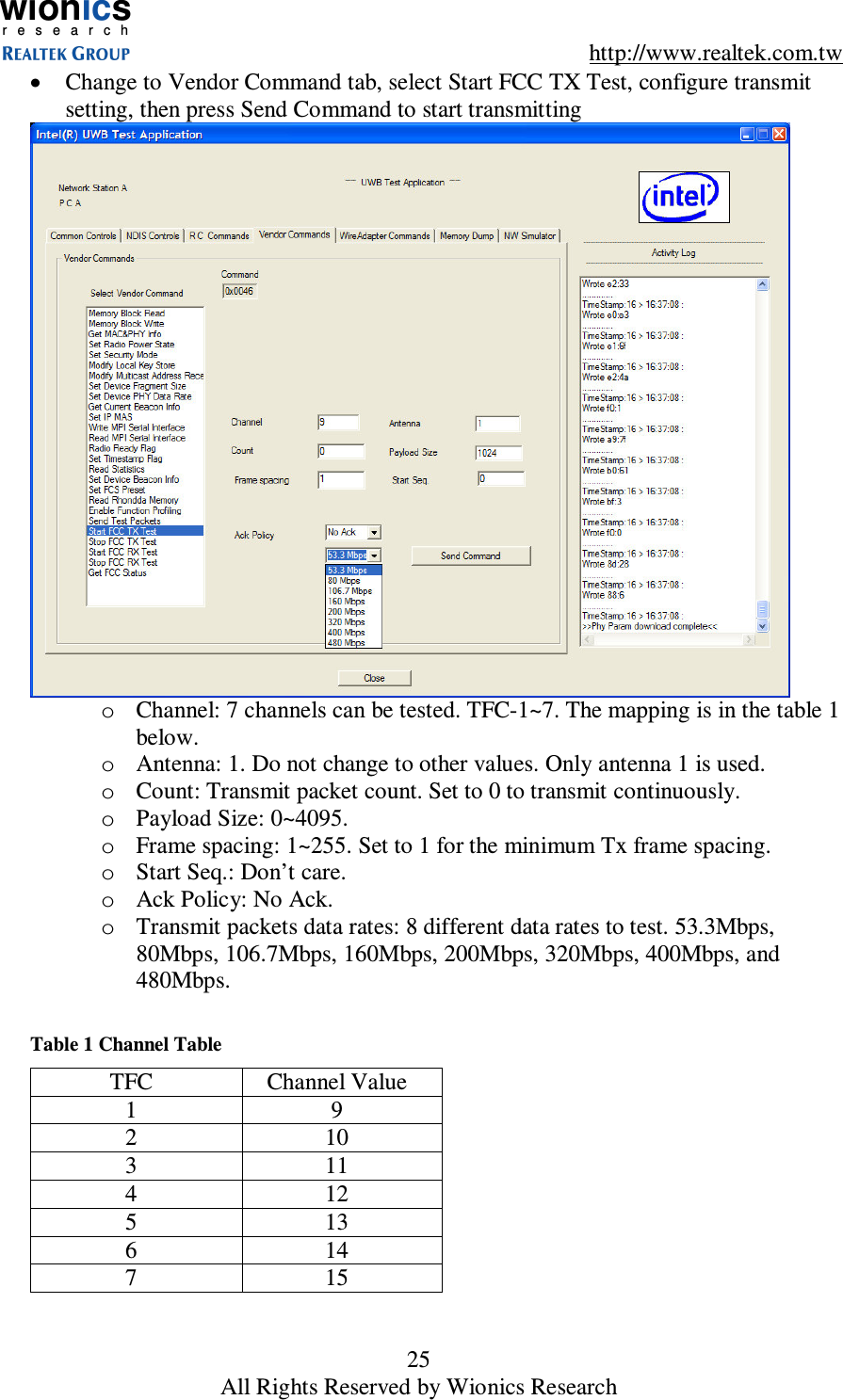
Starix Technology DGLR7CV1 Wireless USB 2.0 Adapter User Manual

Realtek Semiconductor Corp. - Wionics Research Wireless USB 2.0 Adapter Users Manual

Users Manual Document

wionicsr e s e a r c h    http://www.realtek.com.tw 1 All Rights Reserved by Wionics Research      Realtek/Intel UWB Dongle Demo Board  User’s Guide   Revision A                       wionicsr e s e a r c h
wionicsr e s e a r c h    http://www.realtek.com.tw 2 All Rights Reserved by Wionics Research   Table of Contents    1  Introduction ............................................................................................................ 3 2  System Description ................................................................................................. 3 2.1  UWB PHY .................................................................................................. 3 2.2  Intel MAC ................................................................................................... 4 2.3  EEPROM .................................................................................................... 4 3  Software.................................................................................................................. 4 3.1  Driver/Application Installation .................................................................... 4 3.1.1  Setup ....................................................................................................... 4 3.1.2  Driver Installation.................................................................................... 7 3.1.2.1  USB Dongle ............................................................................................ 7 3.1.2.1.1  DFU Driver.......................................................................................... 7 3.1.2.1.2  Control Driver ................................................................................... 10 3.1.2.1.3  HWA(Host Wire Adapter) Driver ...................................................... 14 3.1.2.1.4  WiNet Driver ..................................................................................... 19 3.1.3  Application Operation............................................................................ 23 4  Hardware Interfaces .............................................................................................. 26 4.1  USB Interface............................................................................................ 26 5  Instruction to The User.......................................................................................... 26 6  Document History................................................................................................. 27
wionicsr e s e a r c h    http://www.realtek.com.tw 3 All Rights Reserved by Wionics Research 1  Introduction This  document  describes  the  operations,  interfaces,  and  software  installation  of  the Realtek/Intel UWB USB Dongle Demo Board.  2  System Description Figure 1 shows the system block diagram of the Realtek/Intel UWB USB Dongle Demo Board. UWBPHYUWBPHYIntelMACIntelMACANT1MPI_PHYUSBInterfaceUSBInterface512KbEEPROM512KbEEPROM24MHzXtal24MHzXtal 66MHzXtal66MHzXtal Figure 1 System Block Diagram  The demo system mainly consists of two main chips – (i) UWB PHY, (ii) Intel MAC. A serial EEPROM is required to store proper data/commands for the PHY chip and MAC chip.  To  make  the  system  work  properly,  the  EEPROM  should  be  loaded  with  proper content  by  using proper EEPROM writing equipment through I2C  interface. Two basic clock frequencies are used in the system – 24MHz for MAC and 66MHz for PHY. Some more details of the components are shown in the following sections.   2.1  UWB PHY This  chip  integrates  the  RF  and  baseband  functions  of  a  UWB  PHY  defined  by  the standard.  This  version  of  PHY  chip  is  packaged  in  48-pin  QFN  form  factor.  The analog/RF  section  requires  1.65V  and  3.3V  to  operate.  The  digital  core  operates  with 1.4V and the I/O voltage can support a range of 1.8V~3.3V.
wionicsr e s e a r c h    http://www.realtek.com.tw 4 All Rights Reserved by Wionics Research  2.2  Intel MAC This  MAC  chip(Rhondda-M,  144-pin  BGA)  is  from  Intel  which  has  a  standard  MPI interface  to  communicate  with  a  standard  UWB  PHY,  as  well  as  a  standard  USB  2.0 interface to connect directly to a PC. This chip requires voltages of 1.5V and 3.3V.  2.3  EEPROM This chip  is a  serial EEPROM  from Atmel with  a capacity  of 512Kb. It is used  by  the MAC  to  store the  initialization data  and  command  sequence  required  by  the  MAC  and PHY on start up. This chip requires 2.7V~5V. On the application circuit, it’s powered by 3.3V.  3  Software 3.1  Driver/Application Installation 3.1.1  Setup •  Microsoft  .NET  Frame  2.0  should  be  installed  before  installing  the  software. Please download it from Microsoft web site. •  Make  sure  the  HWA  USB  dongle  is  not  connected  to  the  PC/Laptop.  Execute FCC_setup.exe
wionicsr e s e a r c h    http://www.realtek.com.tw 5 All Rights Reserved by Wionics Research •  Accept license agreement  •  Enter user information  •  Installed directory
wionicsr e s e a r c h    http://www.realtek.com.tw 6 All Rights Reserved by Wionics Research •  Install the program  o  The programs and drivers are install in the directory C:\Program Files\Intel\UWB •  Installed directory    •  Copy all files in the Drivers directory of the software package into the installed directory and overwrite every files, i.e., C:\Program Files\Intel\UWB\Drivers. •  Copy all files in the App directory of the software package into the installed directory and overwrite all files, i.e., C:\Program Files\Intel\UWB\App.
wionicsr e s e a r c h    http://www.realtek.com.tw 7 All Rights Reserved by Wionics Research 3.1.2  Driver Installation 3.1.2.1  USB Dongle 3.1.2.1.1  DFU Driver •  Plug in the dongle, wait for the following dialog  •  Install the drivers from the specified location(C:\Program Files\Intel\UWB\Drivers) manually
wionicsr e s e a r c h    http://www.realtek.com.tw 8 All Rights Reserved by Wionics Research •  Don’t search…  •  Click “Next>”  •  Choose “Have Disk…”
wionicsr e s e a r c h    http://www.realtek.com.tw 9 All Rights Reserved by Wionics Research •  Install the drivers from C:\Program Files\Intel\UWB\Drivers  •  Click “Next>”   •  Click “Continue Anyway”
wionicsr e s e a r c h    http://www.realtek.com.tw 10 All Rights Reserved by Wionics Research •  Click “Finish”  3.1.2.1.2  Control Driver  •  Install the drivers from the specified location(C:\Program Files\Intel\UWB\Drivers) manually
wionicsr e s e a r c h    http://www.realtek.com.tw 11 All Rights Reserved by Wionics Research
wionicsr e s e a r c h    http://www.realtek.com.tw 12 All Rights Reserved by Wionics Research •  Don’t Search…  •  Click “Next>”  •  Choose “Have Disk…”
wionicsr e s e a r c h    http://www.realtek.com.tw 13 All Rights Reserved by Wionics Research •  Install the drivers from C:\Program Files\Intel\UWB\Drivers  •  Click “Next>”  •  Click “Continue Anyway”
wionicsr e s e a r c h    http://www.realtek.com.tw 14 All Rights Reserved by Wionics Research •  Click “Finish”  3.1.2.1.3  HWA(Host Wire Adapter) Driver  •  Install the drivers from the specified location(C:\Program Files\Intel\UWB\Drivers) manually
wionicsr e s e a r c h    http://www.realtek.com.tw 15 All Rights Reserved by Wionics Research  •  Don’t Search…  •  Click “Next>”  •  Click “Have Disk…”
wionicsr e s e a r c h    http://www.realtek.com.tw 16 All Rights Reserved by Wionics Research  •  Install the drivers from C:\Program Files\Intel\UWB\Drivers  •  Click “Next>”  •  Click “Continue Anyway”
wionicsr e s e a r c h    http://www.realtek.com.tw 17 All Rights Reserved by Wionics Research
wionicsr e s e a r c h    http://www.realtek.com.tw 18 All Rights Reserved by Wionics Research •  Click “Finish”   •  Host Wire Adapter is installed
wionicsr e s e a r c h    http://www.realtek.com.tw 19 All Rights Reserved by Wionics Research 3.1.2.1.4  WiNet Driver  •  Install the drivers from the specified location(C:\Program Files\Intel\UWB\Drivers) manually  •  Don’t Search
wionicsr e s e a r c h    http://www.realtek.com.tw 20 All Rights Reserved by Wionics Research  •  Click “Next>”  •  Click “Have Disk…”  •  Install the drivers from C:\Program Files\Intel\UWB\Drivers
wionicsr e s e a r c h    http://www.realtek.com.tw 21 All Rights Reserved by Wionics Research
wionicsr e s e a r c h    http://www.realtek.com.tw 22 All Rights Reserved by Wionics Research •  Click “Have Disk…”  •  Click “Continue Anyway”  •  Click “Finish”
wionicsr e s e a r c h    http://www.realtek.com.tw 23 All Rights Reserved by Wionics Research  •  Both Host Wire Adapter and WiNet Adapter are installed     3.1.3  Application Operation •  Execute the C:\Program Files\Intel\UWB\App\UWB Test Application.exe, and select either Station A, B, or C.
wionicsr e s e a r c h    http://www.realtek.com.tw 24 All Rights Reserved by Wionics Research •  Press #RESET# button in the Commands block of the Common Controls tab  •  Select File1 and press Load PHY Parameters in the PHY Control block to load the PHY parameter file, RTU7010-13RF1.TXT, from the C:\Program Files\Intel\UWB\App directory.
wionicsr e s e a r c h    http://www.realtek.com.tw 25 All Rights Reserved by Wionics Research •  Change to Vendor Command tab, select Start FCC TX Test, configure transmit setting, then press Send Command to start transmitting  o  Channel: 7 channels can be tested. TFC-1~7. The mapping is in the table 1 below. o  Antenna: 1. Do not change to other values. Only antenna 1 is used. o  Count: Transmit packet count. Set to 0 to transmit continuously. o  Payload Size: 0~4095. o  Frame spacing: 1~255. Set to 1 for the minimum Tx frame spacing. o  Start Seq.: Don’t care. o  Ack Policy: No Ack. o  Transmit packets data rates: 8 different data rates to test. 53.3Mbps, 80Mbps, 106.7Mbps, 160Mbps, 200Mbps, 320Mbps, 400Mbps, and 480Mbps.  Table 1 Channel Table TFC  Channel Value 1  9 2  10 3  11 4  12 5  13 6  14 7  15
wionicsr e s e a r c h    http://www.realtek.com.tw 26 All Rights Reserved by Wionics Research  •  Select Stop FCC TX Test and press Send Command to stop transmitting. •  To continue Tx tests with different Tx setting, just change the setting and press Send Command without leaving the Start FCC TX Test. •  Whenever there’s Tx or Rx activities, one of the lights (LED’s) should be blinking. If the light is not blinking, press the Sand Command again. If the light is still not blinking or in any other abnormal situations that the USB dongle is not working correctly, close the application, unplug the dongle, and re-plug the dongle, execute the application and do the test again. •  To enable receive function, just select Start FCC RX test, configure related setting, and press Send Command to start receiving. •  Activity Log window also shows commands result of the dongle being tested.   4  Hardware Interfaces 4.1  USB Interface Table 2 shows the pinout of the USB interface. Table 2 USB Connector Pinout Pin#  Pin Name  Description 1  VBUS  USB BUS Power = 5V 2  Data-(D-, DM on the schematic)  Differential Data Pin - 3  Data+(D+, DP on the schematic)  Differential Data Pin + 4  GND  USB BUS Ground  5  Instruction to The User   This  equipment  has  been  tested  and  found  to  comply  with  the  limits  for  a  class  B digital  device,  pursuant  to  part  15  of  the  FCC  Rules.  These  limits  are  designed  to provide  reasonable  protection against  harmful  interference  in  a  residential  installation. This  equipment  generates,  uses  and  can  radiate  radio  frequency  energy  and  if  not installed and used in accordance with the instructions, may cause  harmful  interference  to  radio  communications.  However,  there  is  no  guarantee  that interference  will  not  occur  in  a  particular  installation.  If  this  equipment  does  cause  harmful interference to radio or television reception,  which can  be determined  by turning the equipment off  and  on,  the  user  is  encouraged  to  try  to  correct  the  interference  by  one  or  more  of  the following measures:  * Reorient or relocate the receiving antenna.  * Increase the separation between the equipment and receiver.   * Connect the equipment  into  an outlet on a circuit  different from  that to which the receiver is connected.
wionicsr e s e a r c h    http://www.realtek.com.tw 27 All Rights Reserved by Wionics Research  * Consult the dealer or an experienced radio/TV technician for help.    This    equipment    has   been   certified   to    comply   with    the   limits   for   a   class   B computing  device, pursuant to  FCC Rules. In order to  maintain compliance with FCC regulations,  shielded  cables  must  be  used  with  this  equipment.  Operation  with  non-approved equipment or unshielded cables is  likely  to  result  in  interference  to  radio  and  TV  reception.  The  user  is  cautioned that  changes  and  modifications  made  to  the  equipment  without  the  approval  of manufacturer  could  void  the user's authority to operate this equipment.  This equipment may only be operated indoors.  Operation outdoors is in violation of 47 USC Section 301 and could subject the operator to serious legal penalties.    6  Document History Date  Revision  Description  Author 02/14/07  A  Initial Release  Ted Lin

Navigation menu