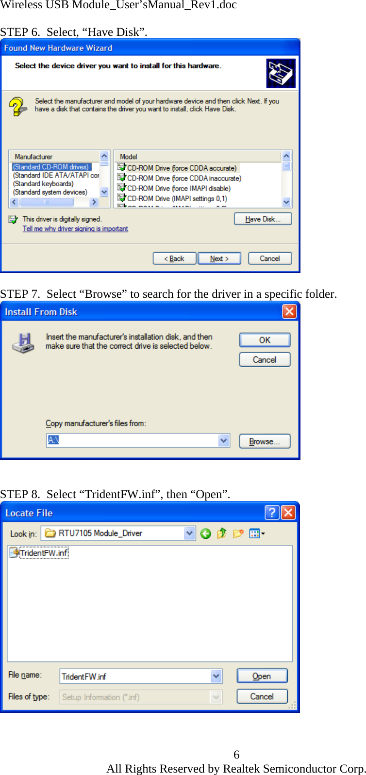
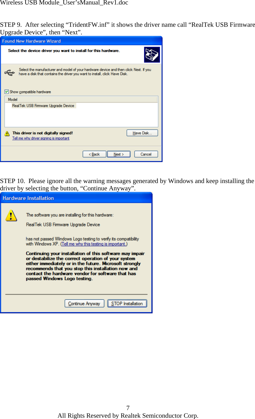
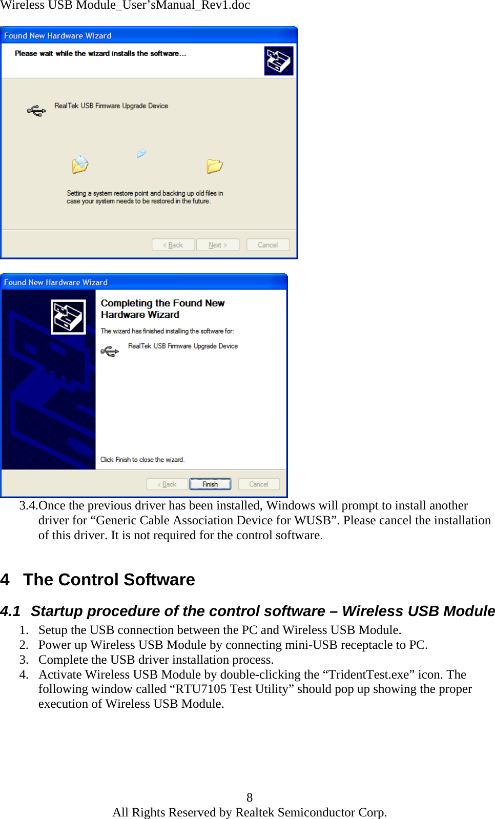
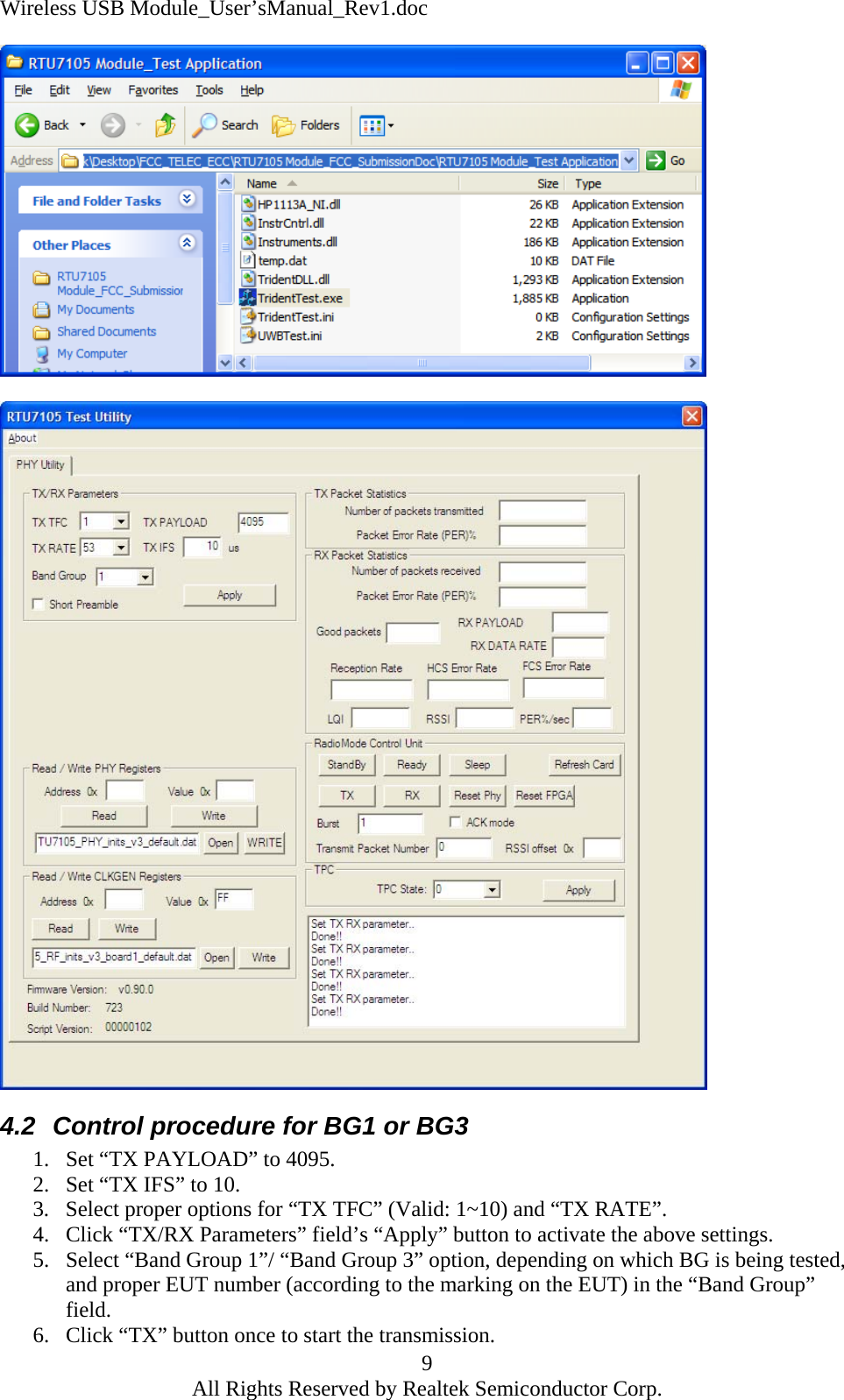
Starix Technology RTU7105-MOD-V3 Wireless USB Module User Manual RTU7105 Module V3 User s Manual

Realtek Semiconductor Corp. - Wionics Research Wireless USB Module RTU7105 Module V3 User s Manual

Users Guide

Wireless USB Module_User’sManual_Rev1.doc     Wireless USB Module User’s Manual  Rev 1       Hak C. Sok1 All Rights Reserved by Realtek Semiconductor Corp.
Wireless USB Module_User’sManual_Rev1.doc  1 Introduction This document describes the system operation of a Wireless USB Module, as well as driver installation and the use of control software.  2 System Operation 2.1 General Description Wireless USB Module is a UWB module. It can be used in various UWB applications, such as 4-port HWA and WUSB docking station.  2.2  System Block Diagram (with a Carrier Board) The following figure shows the system block diagram of a Wireless USB Module and a carrier board. It accepts +5V from a power adapter or +5V from USB device and converts it to various voltages required by the MAC-PHY chip.  Only one crystal is used in the system, which is 66MHz. The system is designed to support both BG1 and BG3 UWB bands as defined in the WiMedia standard. MAC-PHYChip66MHzExternalUSBDeviceUSB connectorExternalPowerAdapterPower socketBG 1 & 3AntennaAntenna connectorPowerManagement           2 All Rights Reserved by Realtek Semiconductor Corp.
Wireless USB Module_User’sManual_Rev1.doc 2.3 Connector Location   Wireless USB Module Carrier Board 3.3 V Regulator  Micro Coaxial connector RTU7105 1.8 V Regulator DC Power JackNot Used Mini-USB Receptacle Type- B 1.2 V Regulator3 Driver Installation 3.1.Setup the USB connection between the PC and Wireless USB Module. 3.2.Power up Wireless USB Module by inserting the connection between the mini-USB receptacle and the PC.  The mini-USB supplies the +5Vdc to the three regulators on the carrier board, which then convert it to various voltages required by the MAC-PHY chip. 3.3.Follow the steps below for the driver installation process. STEP 1.  After plugged in the mini-USB connector, Windows will prompt to install driver for the Found New Hardware Wizard.  3 All Rights Reserved by Realtek Semiconductor Corp.
Wireless USB Module_User’sManual_Rev1.doc  STEP 2.  Select, “No, not this time”, then “Next”.       STEP 3.  Select, “Install from a list or specific location (Advanced)”, then “Next”.       4 All Rights Reserved by Realtek Semiconductor Corp.
Wireless USB Module_User’sManual_Rev1.doc  STEP 4.  Select, “Don’t search, I will choose the driver to install”, then “Next”.      STEP 5.  Select, “Next”.      5 All Rights Reserved by Realtek Semiconductor Corp.
Wireless USB Module_User’sManual_Rev1.doc STEP 6.  Select, “Have Disk”.   STEP 7.  Select “Browse” to search for the driver in a specific folder.    STEP 8.  Select “TridentFW.inf”, then “Open”.    6 All Rights Reserved by Realtek Semiconductor Corp.
Wireless USB Module_User’sManual_Rev1.doc  STEP 9.  After selecting “TridentFW.inf” it shows the driver name call “RealTek USB Firmware Upgrade Device”, then “Next”.    STEP 10.  Please ignore all the warning messages generated by Windows and keep installing the driver by selecting the button, “Continue Anyway”.   7 All Rights Reserved by Realtek Semiconductor Corp.
Wireless USB Module_User’sManual_Rev1.doc    3.4.Once the previous driver has been installed, Windows will prompt to install another driver for “Generic Cable Association Device for WUSB”. Please cancel the installation of this driver. It is not required for the control software.  4  The Control Software 4.1  Startup procedure of the control software – Wireless USB Module 1.  Setup the USB connection between the PC and Wireless USB Module. 2.  Power up Wireless USB Module by connecting mini-USB receptacle to PC. 3.  Complete the USB driver installation process. 4.  Activate Wireless USB Module by double-clicking the “TridentTest.exe” icon. The following window called “RTU7105 Test Utility” should pop up showing the proper execution of Wireless USB Module. 8 All Rights Reserved by Realtek Semiconductor Corp.
Wireless USB Module_User’sManual_Rev1.doc    4.2  Control procedure for BG1 or BG3 1.  Set “TX PAYLOAD” to 4095.   2.  Set “TX IFS” to 10. 3.  Select proper options for “TX TFC” (Valid: 1~10) and “TX RATE”. 4.  Click “TX/RX Parameters” field’s “Apply” button to activate the above settings. 5.  Select “Band Group 1”/ “Band Group 3” option, depending on which BG is being tested, and proper EUT number (according to the marking on the EUT) in the “Band Group” field.  9 6.  Click “TX” button once to start the transmission. All Rights Reserved by Realtek Semiconductor Corp.

Navigation menu