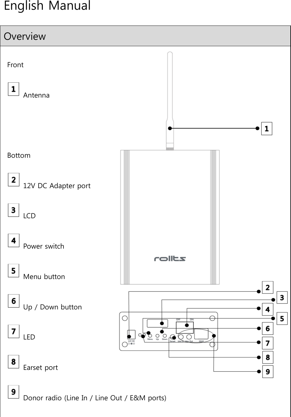
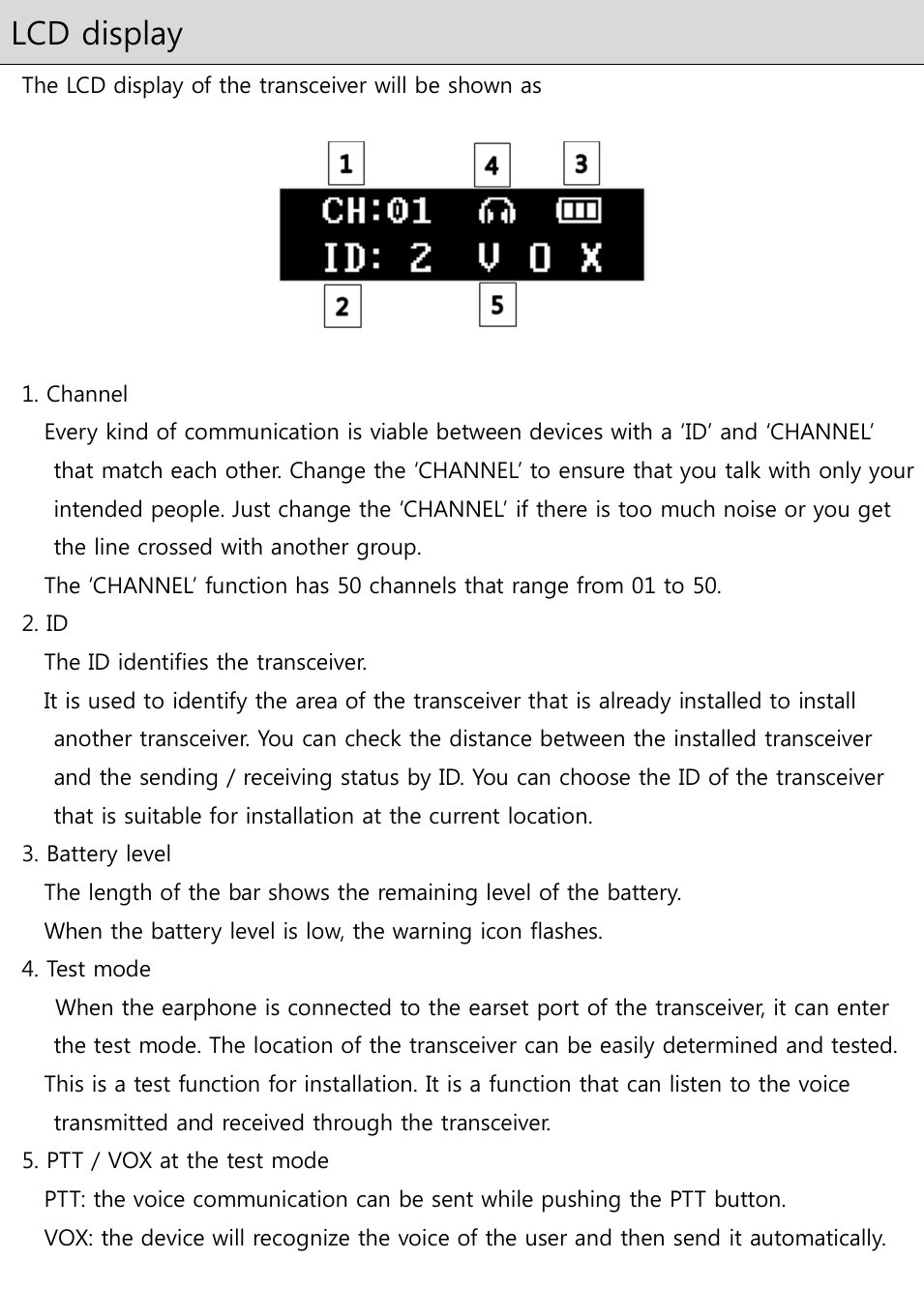
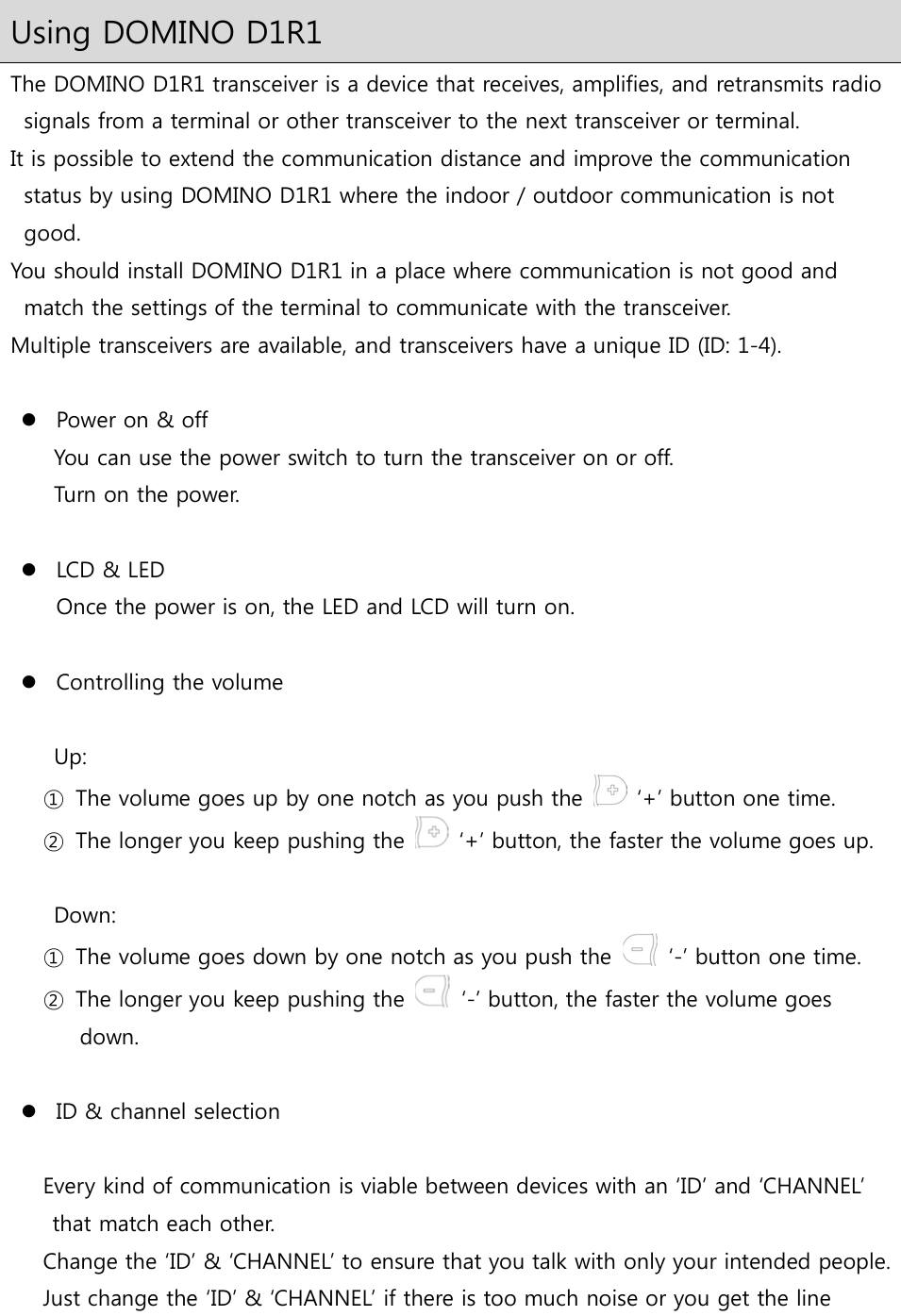
Starnex DOMINOD1R1 Digital Transceiver User Manual

Starnex Co., Ltd. Digital Transceiver

User Manual

English Manual Overview  Front    Antenna     Bottom    12V DC Adapter port    LCD    Power switch    Menu button    Up / Down button    LED    Earset port    Donor radio (Line In / Line Out / E&M ports)
 LCD display   The LCD display of the transceiver will be shown as      1. Channel Every kind of communication is viable between devices with a ‘ID’ and ‘CHANNEL’ that match each other. Change the ‘CHANNEL’ to ensure that you talk with only your intended people. Just change the ‘CHANNEL’ if there is too much noise or you get the line crossed with another group.   The ‘CHANNEL’ function has 50 channels that range from 01 to 50.   2. ID       The ID identifies the transceiver.   It is used to identify the area of the transceiver that is already installed to install another transceiver. You can check the distance between the installed transceiver and the sending / receiving status by ID. You can choose the ID of the transceiver that is suitable for installation at the current location.   3. Battery level       The length of the bar shows the remaining level of the battery.       When the battery level is low, the warning icon flashes.   4. Test mode         When the earphone is connected to the earset port of the transceiver, it can enter the test mode. The location of the transceiver can be easily determined and tested. This is a test function for installation. It is a function that can listen to the voice transmitted and received through the transceiver.   5. PTT / VOX at the test mode PTT: the voice communication can be sent while pushing the PTT button.       VOX: the device will recognize the voice of the user and then send it automatically.
 Usage  Market, Hotel, Sports, Leisure (Hiking, Climbing), Guide, Conference, Etc.  Type - High usability for any model (portable / fixed). - All possible for both portable and fixed use regardless of outdoor and indoor.  Communication - Secures own local communication network by building a small-scale communication network.  Distance - Extends the communication distance infinitely through relay between transceivers.  High receiving sensitivity - Receives weak signal and sends it with high-quality communication signal.  Built-in battery - Works with built-in battery when power is not available. - Chargeable power is DC 12 V.  Donor radio functions - Connects with other transceivers all around world through the gateway (or router / switch), and using the Line in/out ports or the E&M port.  Contents                                                       Transceiver            Brackets         Screws          Expansion anchors            User guide
Using DOMINO D1R1 The DOMINO D1R1 transceiver is a device that receives, amplifies, and retransmits radio signals from a terminal or other transceiver to the next transceiver or terminal. It is possible to extend the communication distance and improve the communication status by using DOMINO D1R1 where the indoor / outdoor communication is not good. You should install DOMINO D1R1 in a place where communication is not good and match the settings of the terminal to communicate with the transceiver. Multiple transceivers are available, and transceivers have a unique ID (ID: 1-4).   Power on & off You can use the power switch to turn the transceiver on or off. Turn on the power.   LCD & LED Once the power is on, the LED and LCD will turn on.   Controlling the volume  Up:   ①  The volume goes up by one notch as you push the    ‘+’ button one time. ②  The longer you keep pushing the    ‘+’ button, the faster the volume goes up.  Down:   ①  The volume goes down by one notch as you push the    ‘-’ button one time. ②  The longer you keep pushing the    ‘-’ button, the faster the volume goes down.   ID & channel selection  Every kind of communication is viable between devices with an ‘ID’ and ‘CHANNEL’ that match each other.   Change the ‘ID’ & ‘CHANNEL’ to ensure that you talk with only your intended people. Just change the ‘ID’ & ‘CHANNEL’ if there is too much noise or you get the line
crossed with another group.   The ‘ID’ function has a unique ID (ID: 1-4). The ‘CHANNEL’ function has 50 channels that range from 01 to 50.  Move to ‘ID’ or ‘CHANNEL’ by using the    ‘-’ or    ‘+’ buttons after pushing the menu in the main screen.  Select it by pushing the    menu button.  If the first number flashes, adjust it by using the    ‘-’ or    ‘+’ buttons.  Move to the next number by pushing the    menu button.  If the number flashes, adjust it by using the    ‘-’ or    ‘+’ buttons.  Once the last number has been changed, push the    menu button and the number will stop flashing.  Move to another menu by using the    ‘-’ or    ‘+’ buttons or go back to the main screen by pushing the    menu button.   Donor radio (Line In, Line Out, E&M ports) Connects with other DOMINOs all around world through the TCP/IP server with Line In, Line Out, or E&M ports. Enables on-line communication between DOMINOs and other types of communication devices using Line In, Line Out, or E&M ports.
Features Manual Features  900 MHz ISM license-free band  Frequency hopping spread spectrum (FHSS) Resistant to narrowband interference and difficult to intercept. Bandwidth used more efficiently.  Encryption (AES-256) Making eavesdropping impossible, even when set to the same channel and group using encryption technology.  Supports both 20,000mAh high-capacity battery Long-time power supply with high-capacity built-in battery in case of power failure or emergency.   General Specifications Frequency   : 900 MHz ISM FHSS Contact List Capacity   : 50 ch (1,000 groups/ch) Encryption   : AES-256 Dimensions (H x W x D)   : 7.8" x 4.7" x 1.97" (199.5 mm x 120 mm x 50 mm) (Except antenna) Weight    : 46 oz. (1.31 kg) (Including 65g bracket and 342g internal battery) Power Source (Built in battery)   : Li-polymer battery @ DC 3.7 V / 20,000 mAh DC power jack : External(-) 5.5 mm, internal(+) 2.1 mm Earset Port   : 3.5 mm 4 pole headset connection  Line In Port   : 3.5 mm 4 pole connector, inbound audio 1 Vp-p Line Out Port
: 3.5 mm 4 pole connector, outbound audio 1 Vp-p E&M Port   : RJ 45 connector, radio audio-in and audio-out 1 Vp-p   Receiver Specifications Frequency Stability   : +/- 2 ppm Spurious Emissions Radiated   : < 43.5 dBuV/m Blocking Immunity +/- 1 MHz   : 79 dB Audio Output   : E&M port audio-out 1 Vp-p : Earphone: 50 mW   Transmitter Specifications RF Output   : Up to 1 W Frequency Stability   : +/- 2 ppm Operating Frequency   : 902.6 ~ 927.5 MHz (Center: 914.5 MHz) Spurious Emissions Radiated   : < 54 dBuV/m FCC Modulation   : GFSK 900 MHz ISM FHSS
FCC information to user  Federal Communications Commission statement  NOTE : Change or modification not expressly approved by the party responsible for Compliance could void the user’s authority to operate the equipment.  NOTE : This equipment has been tested and found to comply with the limits for a Class B digital device, pursuant to Part 15 of the FCC Rules. These limits are designed to provide reasonable protection against harmful interference in a residential installation. This equipment generates, uses and can radiate radio frequency energy and, if not installed and used in accordance with the instructions, may cause harmful interference to radio communications. However, there is no guarantee that interference will not occur in a particular installation. If this equipment does cause harmful interference to radio or television reception which can be determined by turning the equipment off and on, the user is encouraged to try to correct the interference by one or more of the following measures. - Reorient or relocate the receiving antenna. - Increase the separation between the equipment and receiver. - Connect the equipment into an outlet on a circuit different from that to which the receiver is connected. - Consult the dealer or an experienced radio, TV technician for help. - Only shielded interface cable should be used. Finally, any changes or modifications to the equipment by the user not expressly approved by the grantee or manufacturer could void the user’s authority to operate such equipment,   NOTE : Exposure to Radio Frequency Radiation. Antenna shall be mounted in such a manner to minimize the potential for human contact during normal operation.  The antenna should not be contacted during operation to avoid the possibility of exceeding the FCC radio frequency exposure limit.  NOTE : The antenna(s) used for this device must be installed to provide a separation distance of at least 20 cm from all persons and must not be co-located or operating in conjunction with any other antenna or transmitter.  NOTE : This device complies with part 15 of the FCC Rules.  NOTE : Operation is subject to the following two Conditions : (1) This device may not cause harmful interference, and (2) This device must accept any interference received, including interference that may cause undesired operation.    NOTE : This appliance and its antenna must not be co-located or operated in conjunction with any other antenna or transmitter.

Navigation menu