Stasis Labs STSLBMV1 Stasi Monitor User Manual GPD 0001 Rev B Users Manualx
Stasis Labs, Inc. Stasi Monitor GPD 0001 Rev B Users Manualx
UserManual.wiki
>
Stasis Labs
>
STSLBMV1 User Manual
Appendix 9_User Manual
Navigation menu
Upload a User Manual
Namespaces
Wiki Guide
HTML
PDF
Info
Views
User Manual
Discussion / Help
Navigation
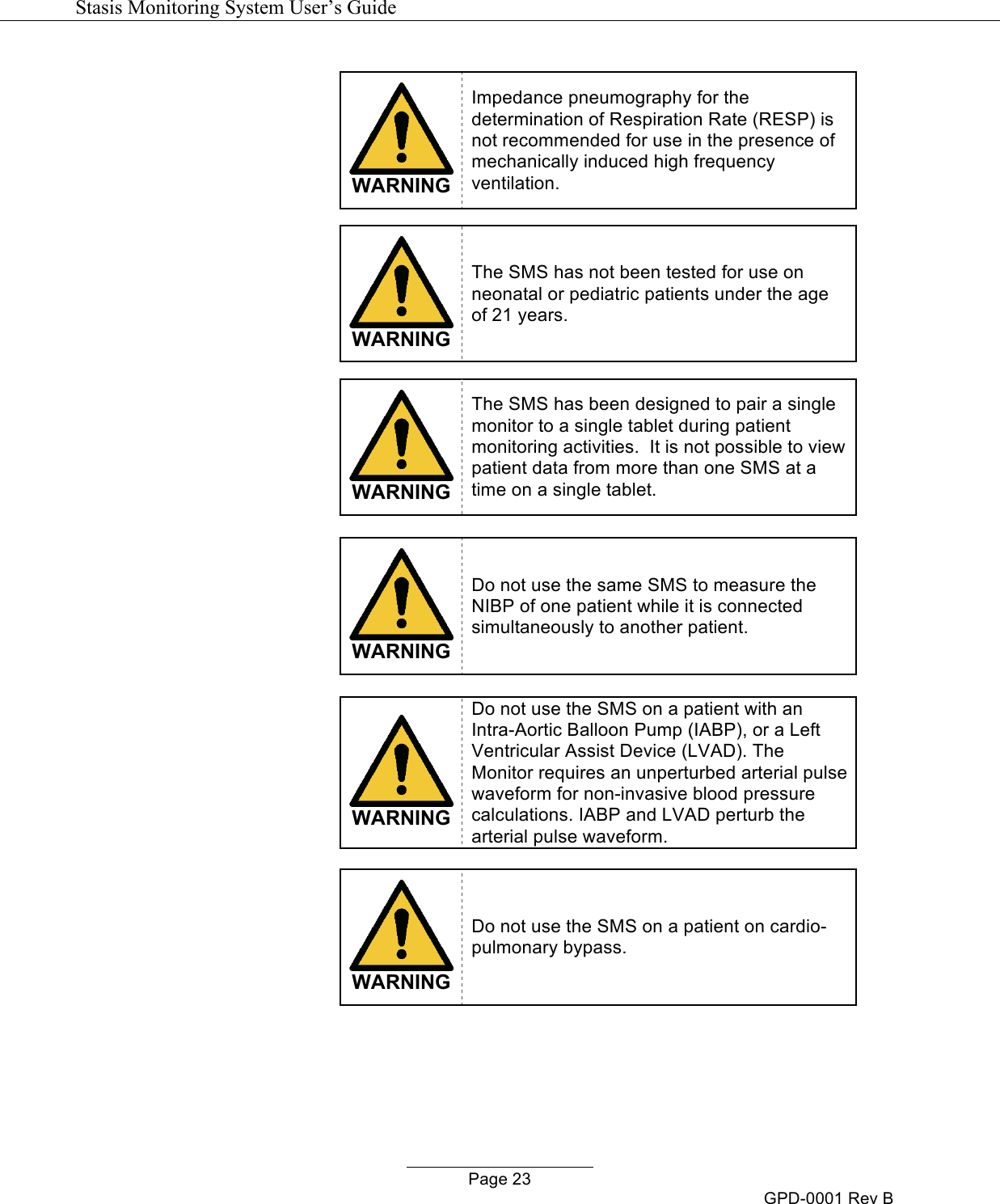

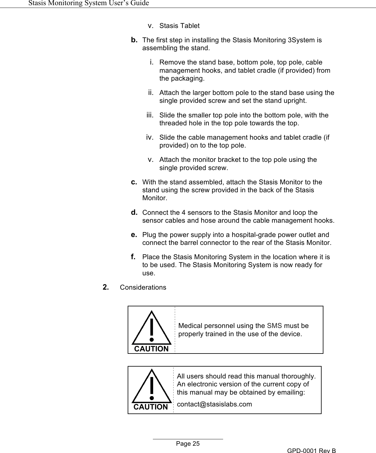
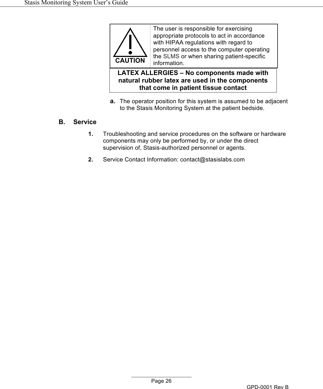
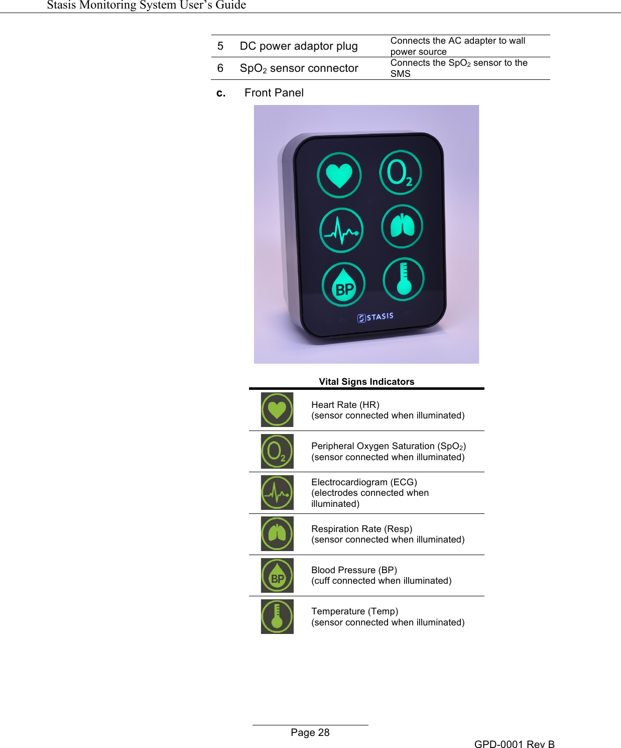
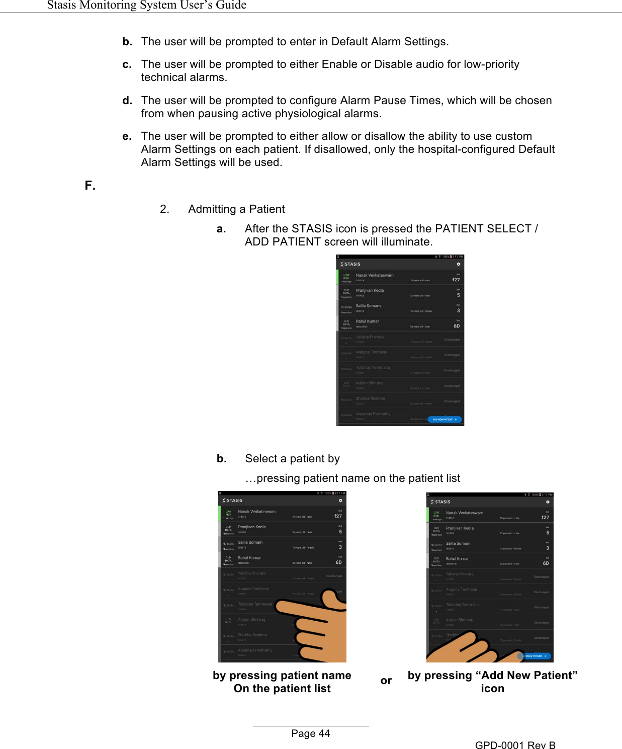
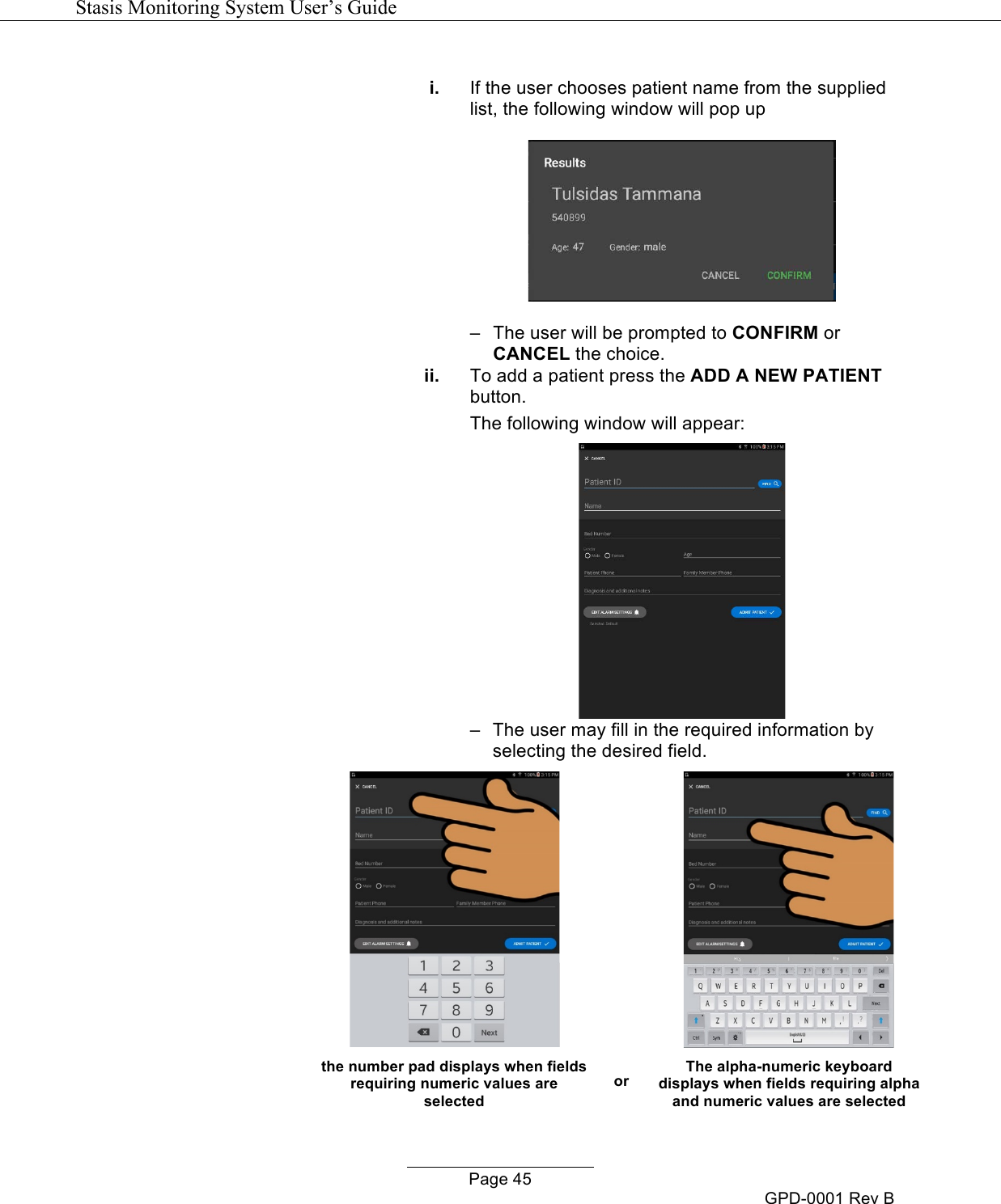
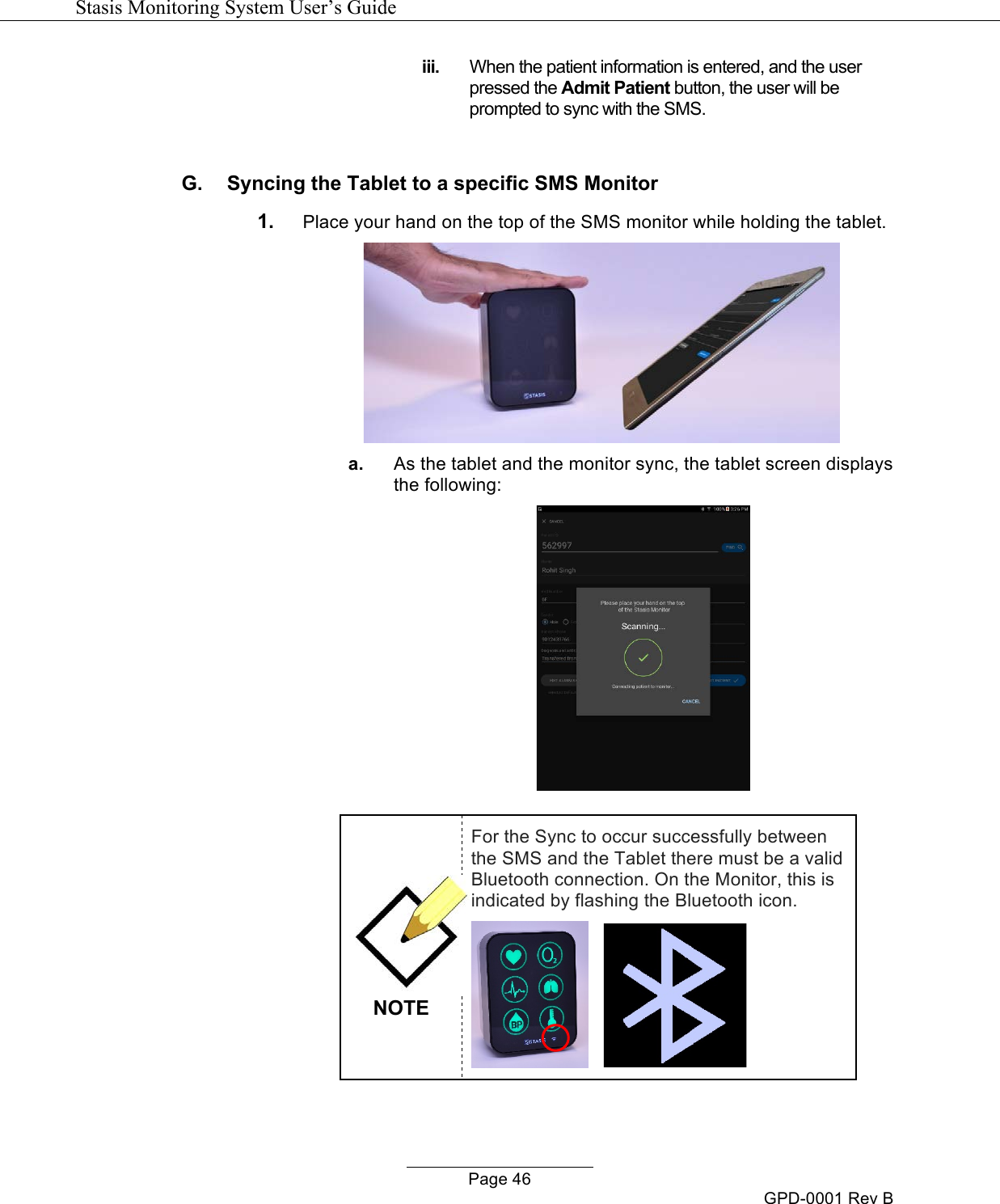
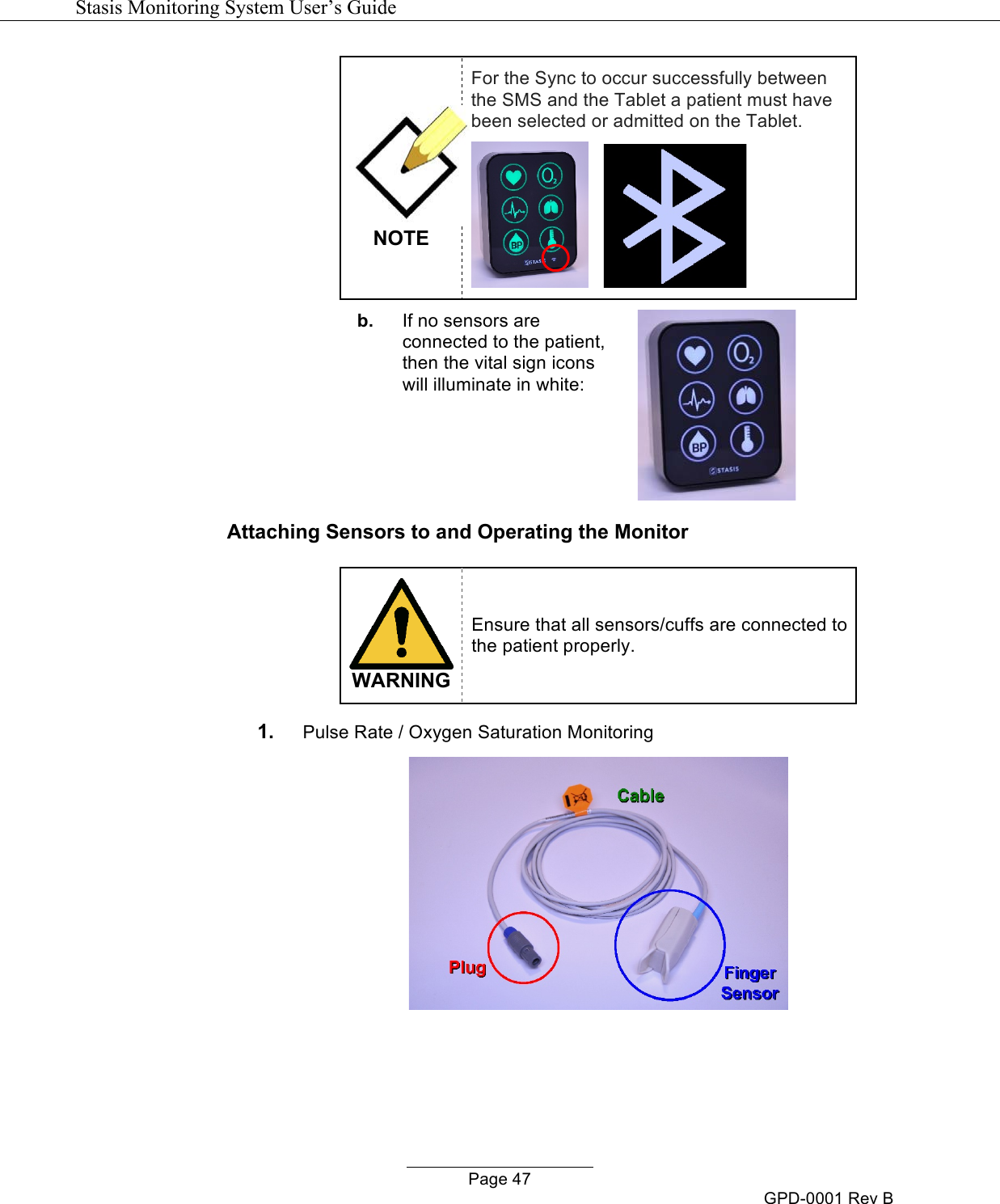
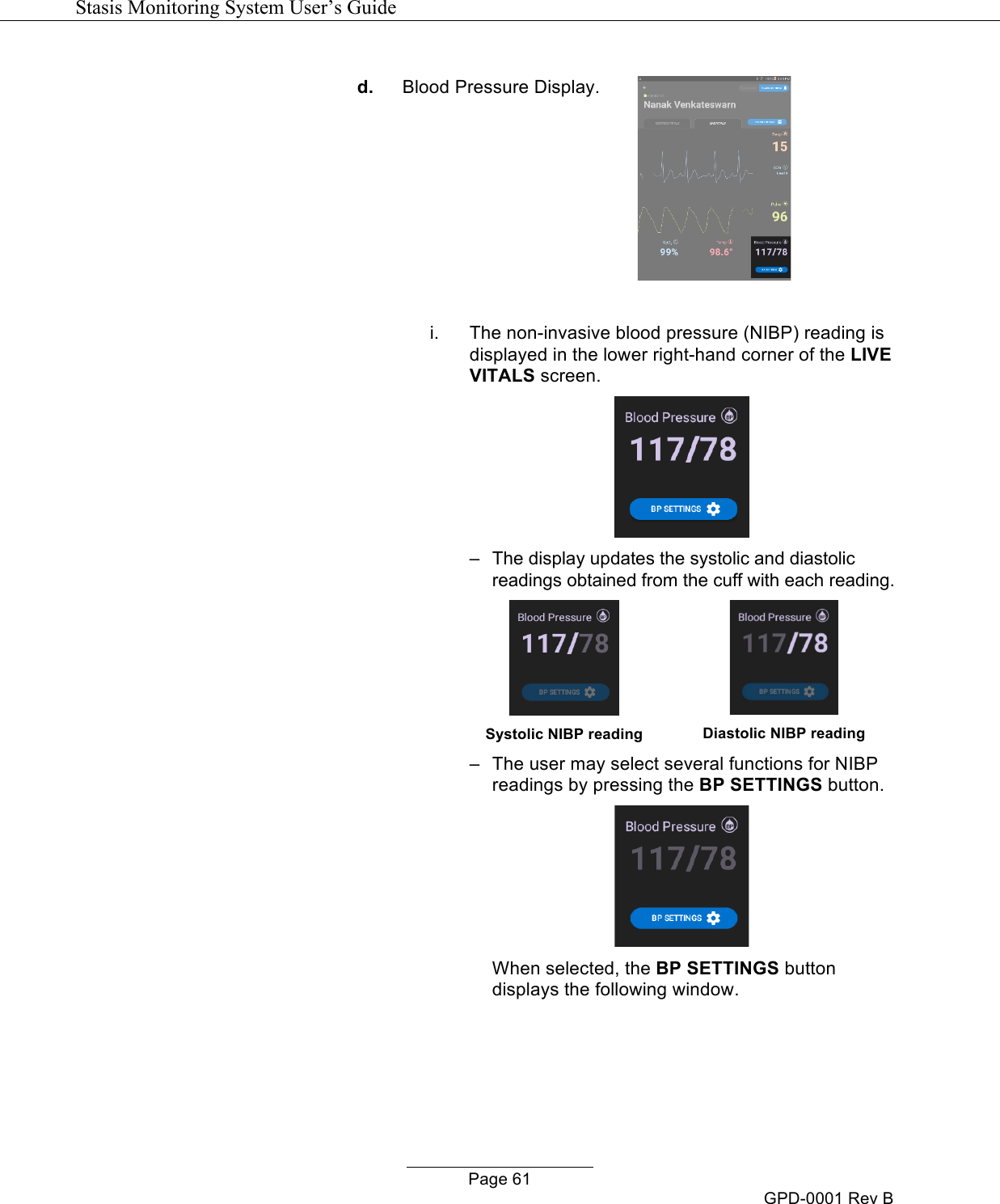
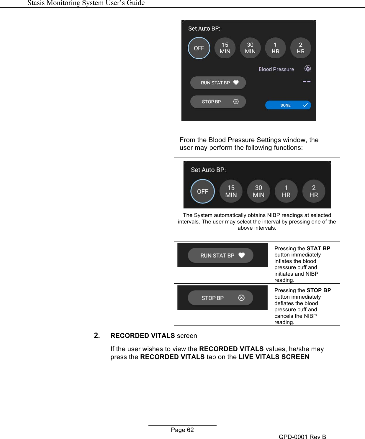
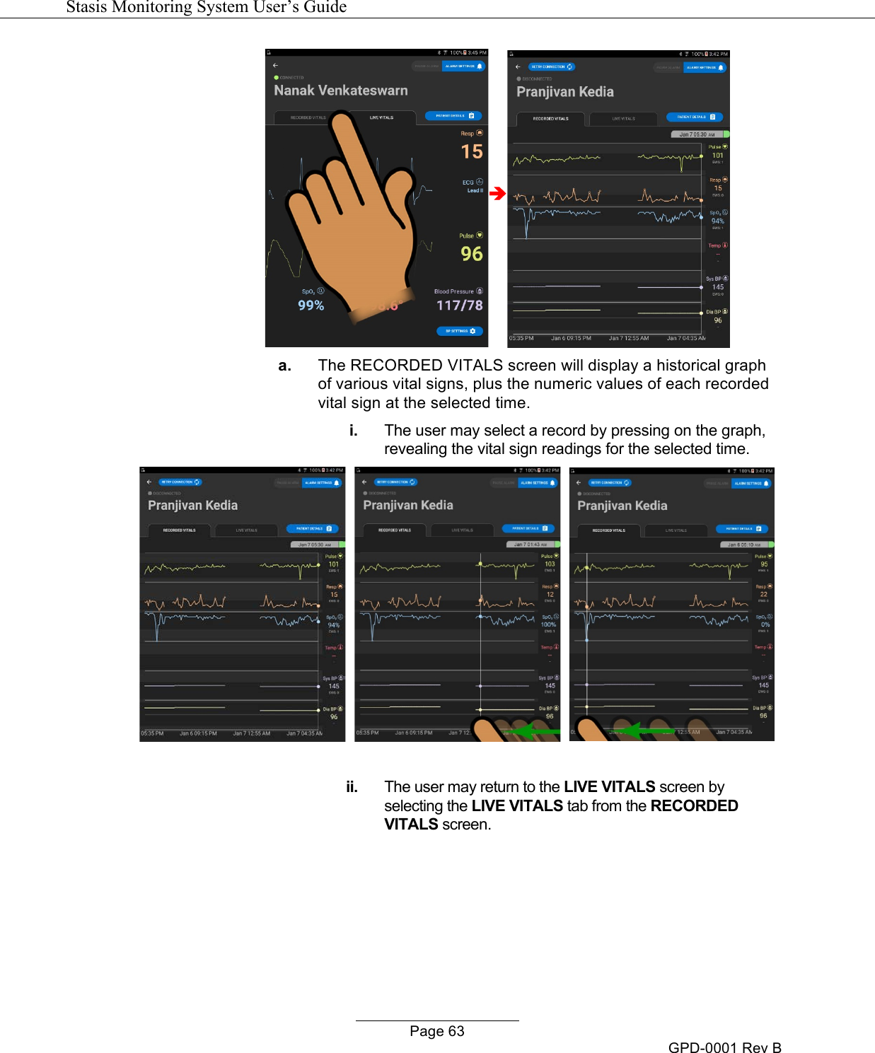
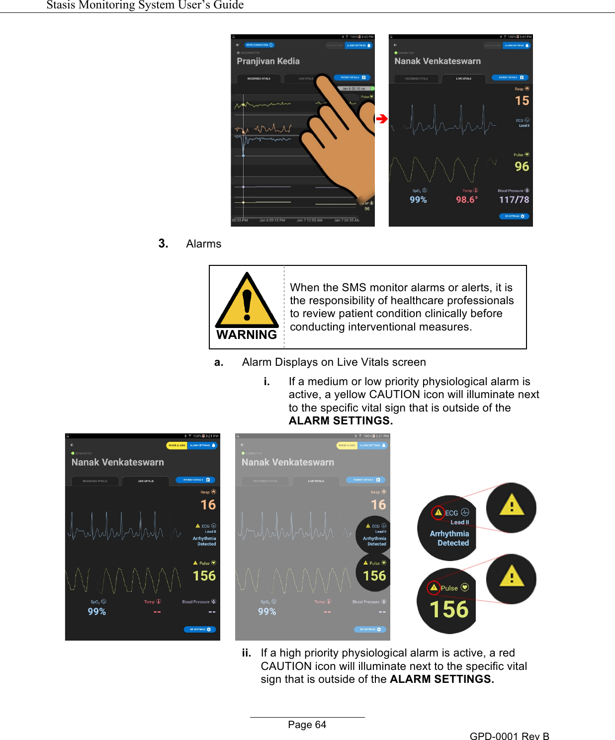
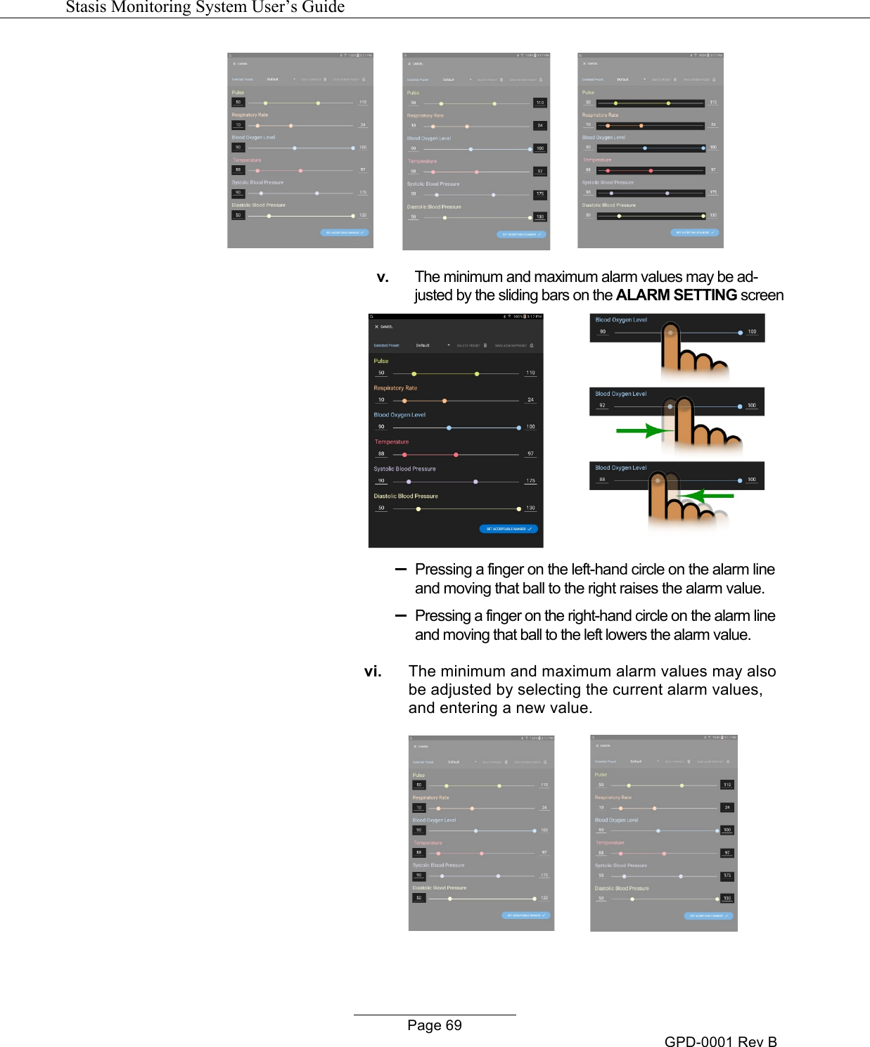
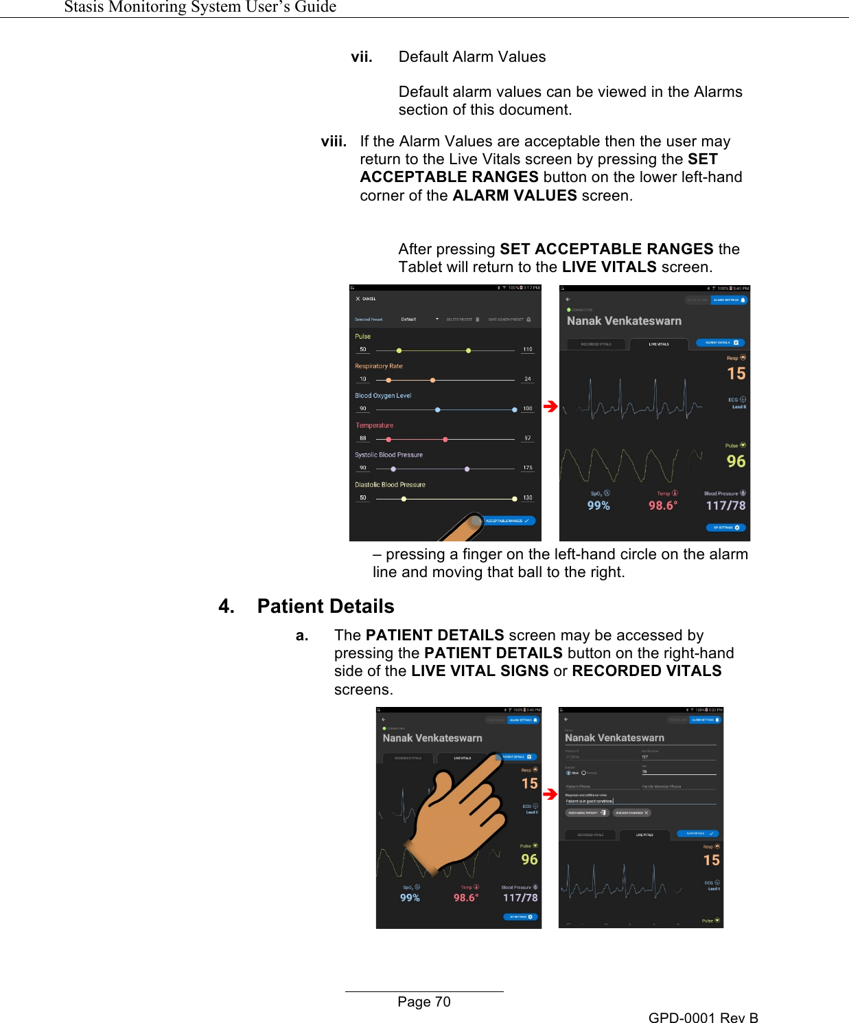
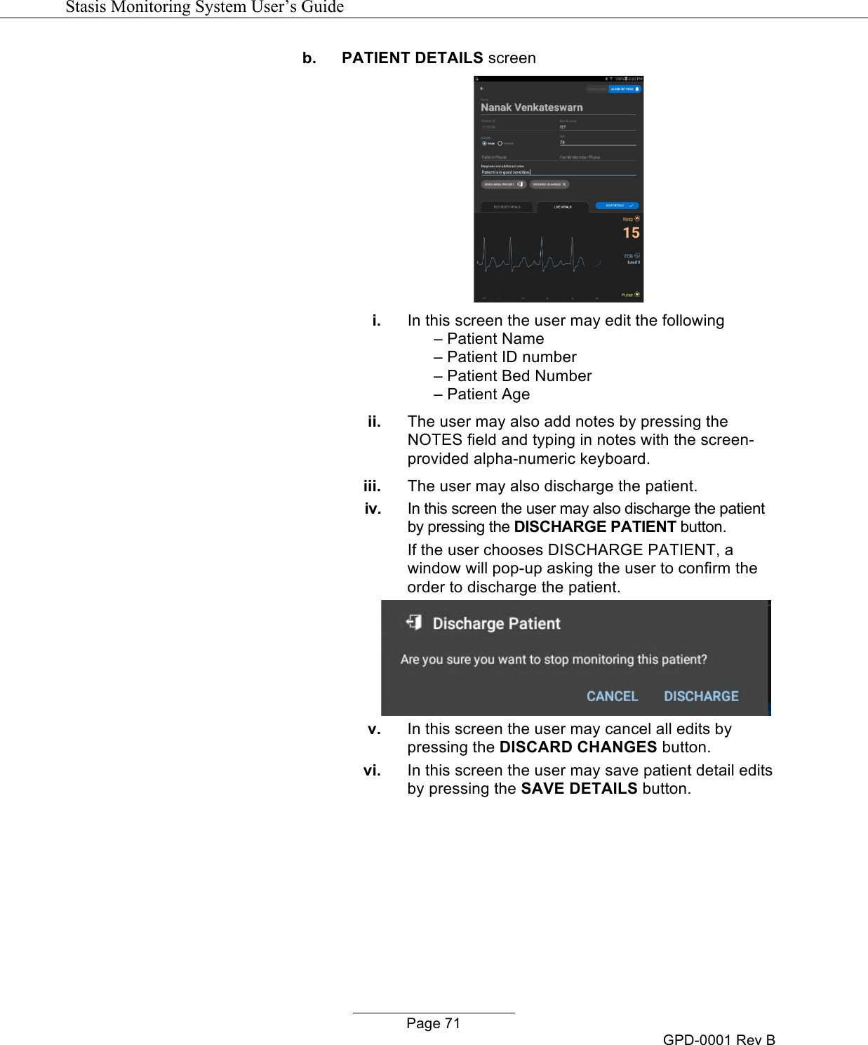
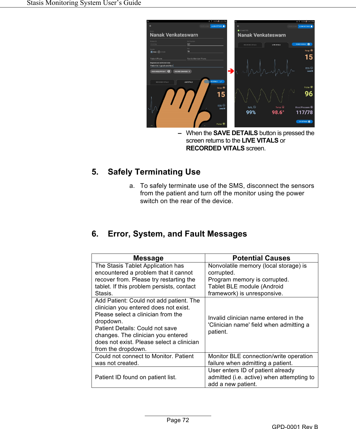
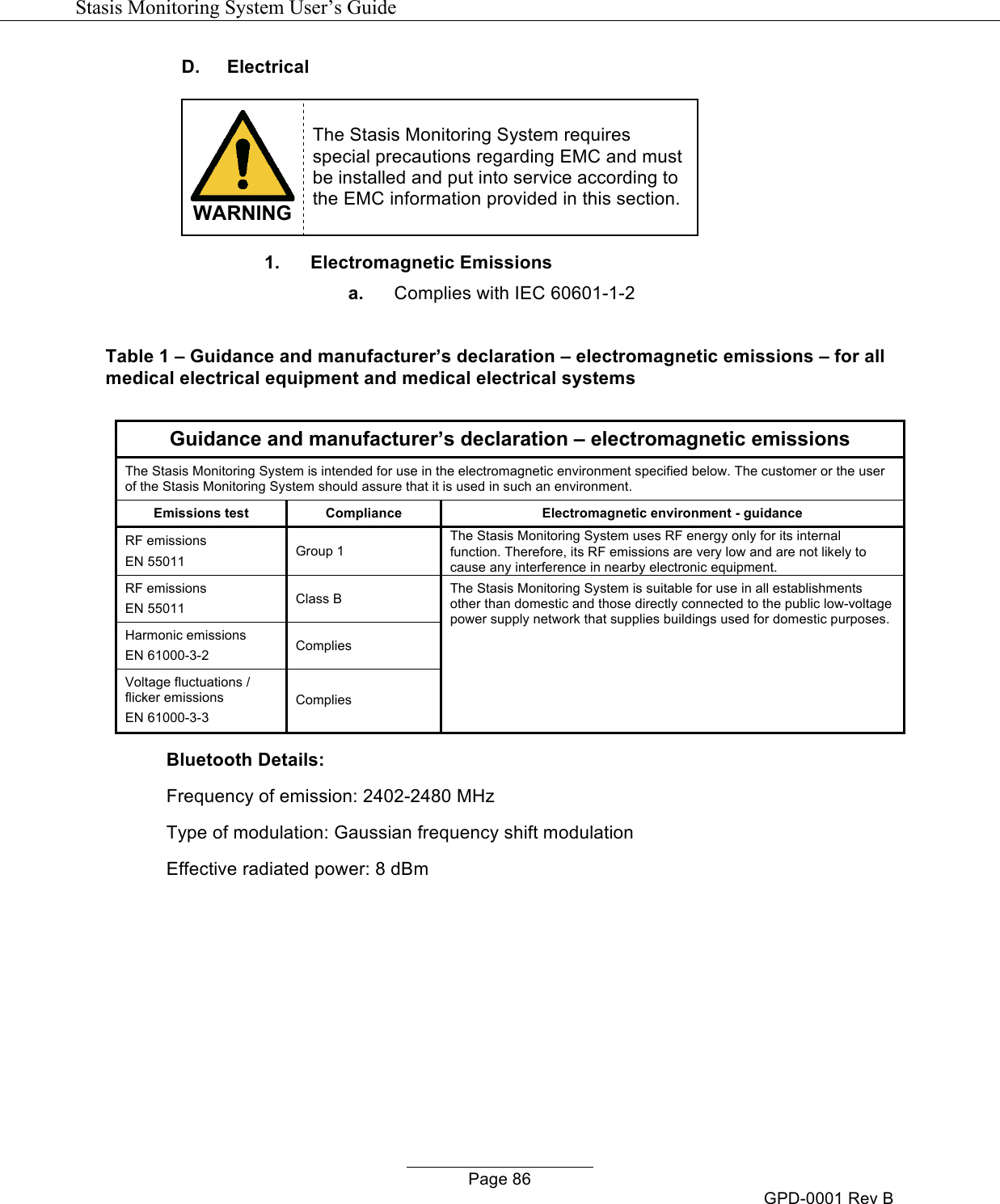
![Stasis Monitoring System User’s Guide Page 27 GPD-0001 Rev B VIII. SYSTEM SET-UP A. Components WARNING Only use the accessories, sensors, cuffs, and cables described below with the SMS. 1. Stasis Monitor a. Physical Characteristics i. Size: 13.3cm(T) X 10.3cm(W) X 7.2cm(D)* [5.38”(T) X 4.07”(W) X 3.88”(D)*] * D (depth) does not include the protrusion of the sensor connectors in the rear nor the room required for sensor cables. b. Back Panel 1 Power on/off switch Rocker switch. Rock to “1” to power on and rock to “0” to power off. 2 NIBP connector Connects the NIBP cuff to the SMS 3 ECG connector Connects the ECG leads to the SMS 4 Temperature connector Connects the temperature sensor to the SMS 1 2 3 4 6 5](https://usermanual.wiki/Stasis-Labs/STSLBMV1/User-Guide-3792063-Page-29.png)