Stasis Labs STSLBMV1 Stasi Monitor User Manual GPD 0001 Rev B Users Manualx
Stasis Labs, Inc. Stasi Monitor GPD 0001 Rev B Users Manualx
Appendix 9_User Manual

Stasis Monitoring System User’s Guide
Page 1
GPD-0001 Rev B
STASIS MONITORING SYSTEM
USER MANUAL
Table of Contents
I. SYMBOLS USED IN USER MANUAL page 1
II. SYMBOLS USED IN DEVICE LABELING page 2
III. ACRONYMS USED page 4
IV. OVERVIEW page 5
V. INTENDED USE page 6
VI. WARNINGS AND CAUTIONS page 7
VII. USE CONSIDERATIONS page 22
VIII. SYSTEM SET-UP page 27
IX. SYSTEM USE page 39
X. ALARMS……………………………………………...…...……page 73
XI. SYSTEM MAINTENANCE page 78
XII. OPERATING CONDITIONS page 83
XIII. TECHNICAL SUPPORT page 93
XIV. RECORDS page 93

Stasis Monitoring System User’s Guide
Page 2
GPD-0001 Rev B
NOTE: This user’s guide is provided as an initial outline for
review by Stasis. It is intended to provide a first
review for Stasis personnel to confirm that the higher-
level information covers needed topics and to guide
fulfilling the scope of the project.
Stasis Monitoring System User’s Guide
Page 1
GPD-0001 Rev B
I. SYMBOLS USED IN USER MANUAL
Symbol
Description
WARNING
A Warning indicates a hazardous
situation which, if not avoided,
could result in death or serious
injury.
Symbol
Description
CAUTION
A Caution indicates a hazardous
situation which, if not avoided,
could result in minor or moderate
injury or could result in property
damage. This manual treats
violation of HIPAA guidelines as a
minor injury warranting a caution
alert.
Symbol
Description
NOTE
Notes provide additional useful
information.
Stasis Monitoring System User’s Guide
Page 2
GPD-0001 Rev B
II. SYMBOLS USED IN DEVICE LABELING
Symbol
Description
WARNING
Warnings are identified by the
WARNING symbol shown at left.
A Warning indicates a hazardous
situation which, if not avoided,
could result in death or serious
injury.
Symbol
Description
REFER TO
INSTRUCTIONS
This symbol prompts the user
to refer to the user manual
before using the Stasis
Monitoring System.
Symbol
Description
DATE OF
MANUFACTURE
This symbol indicates the
year that the Stasis Monitor
was manufactured in.
Stasis Monitoring System User’s Guide
Page 3
GPD-0001 Rev B
Symbol
Description
CLASS II
This symbol indicates that the
Stasis Monitor is a Class II device.
Symbol
Description
TYPE CF
This symbol indicates that the
Stasis Monitor is a Type CF device
intended for defibrillation-
protected direct conductive
contact with the heart.
Symbol
Description
TYPE REF
This symbol precedes the model
designation of the Stasis Monitor.
Symbol
Description
SERIAL
NUMBER
This symbol precedes the serial
number of the Stasis Monitor.
Stasis Monitoring System User’s Guide
Page 4
GPD-0001 Rev B
Symbol
Description
DC POWER
This symbol indicates that the
Stasis Monitor accepts DC power
input.
III. ACRONYMNS USED
A. SMS – Stasis Monitoring System
B. EWS – Early Warning Score
C. ECG – Electrocardiogram
D. SpO2 – Peripheral Capillary Oxygen Saturation
E. HR – Heart Rate
F. BPM – Beats per Minute
G. RPM – Respirations per Minute
H. Temp – Skin Temperature
I. BP – Blood Pressure
J. NIBP – Non-Invasive Blood Pressure
K. IBP – Invasive Blood Pressure
L. SYS – Systolic Blood Pressure
M. DIA – Diastolic Blood Pressure
N. VSR – Vital Sign Records
O. UG – User’s Guide
P. IFU – Instructions for Use
Q. VAC – Volts, Alternating Current
R. VDC – Volts, Direct Current
S. V/m – Volts per Meter (a measurement of electric field strength)
T. Vrms – Volts root mean square (a measurement of electric field strength)
Stasis Monitoring System User’s Guide
Page 5
GPD-0001 Rev B
IV. OVERVIEW
A. The Stasis Monitoring System consists of a compact six-parameter vital signs
monitor that sits at patient bedside and communicates via Bluetooth with Android
tablets running our proprietary application. System uses traditional wired sensor
technology to acquire the vital signs. The primary data display and control for the
monitoring system is on the Android tablet.
B. The model name of the hardware component of the Stasis Monitoring System is
the “Stasis Monitor”.
C. The Stasis Monitor is manufactured for Stasis Labs by:
Johari Digital Healthcare Ltd.
G-582-584, EPIP, Boranada
Salawas Road, Basni Silawatan
Rajasthan - 342014, India
CAUTION
All users should read this manual
thoroughly. An electronic version of the
current copy of this manual may be
obtained by emailing:
contact@stasislabs.com
CAUTION
Review the intended use and warnings
and cautions sections in this manual.
Stasis Monitoring System User’s Guide
Page 6
GPD-0001 Rev B
V. INTENDED USE
The Stasis Monitoring System is intended for use by clinicians and medically
qualified personnel for single or multi-parameter vital signs monitoring of adult patients
(21 years of age or older). It is indicated for 3 lead ECG, respiration rate (RESP), heart
rate (HR), noninvasive blood pressure (NIBP), noninvasive monitoring of functional
oxygen saturation of arterial hemoglobin (SpO2), pulse rate (PR), and skin temperature
(TEMP) in hospital-based facilities; including, general medical-surgical floors,
intermediate care floors, and emergency departments. The Stasis Monitoring System
includes bedside Patient Monitors that communicate with mobile Tablets through
wireless Bluetooth Low Energy (BLE) communication. The Stasis Monitoring System
can generate alerts when rate-based cardiac arrhythmias such as asystole are
detected, and when physiological vital signs fall outside of selected parameters. The
Stasis Monitoring System has a notification system that communicates data and alarms
to a Stasis Tablet. It is intended to supplement the primary alarms which originate at the
Stasis Monitor device.
CAUTION
Federal Law (USA) restricts this device to
sale by or on an order of a physician.
CAUTION
The use of the Stasis Monitoring System
is restricted to one patient at a time.
NOTE
Hospital use typically covers such areas
as general care floors, operating rooms,
special procedural areas, intensive and
critical care areas, or other regions within
the hospital. Use with any particular
patient requires the selection of
appropriate sensors as described in this
manual.
Stasis Monitoring System User’s Guide
Page 7
GPD-0001 Rev B
Essential Performance
For the Stasis Labs Monitoring System, Essential Performance is defined as:
A) The ability to detect 3 lead ECG, respiration rate (RESP), and heart rate (HR) as per
IEC 60601-2-27, noninvasive blood pressure (NIBP) as per IEC 80601-2-30,
noninvasive monitoring of functional oxygen saturation of arterial hemoglobin (SpO2) as
per ISO 80601- 2-61, and skin temperature (TEMP) as per ISO 80601-2-56.
B) The ability to provide alarms if any of items listed in A above go above or fall below
pre-specified limits (as applicable) as per IEC 60601-1-8.
VI. WARNINGS AND CAUTIONS
A. Warnings Summary
WARNING
Before using the SMS carefully read this
user’s guide, including all warnings, cautions,
and instructions.
WARNING
The SMS is intended for patient assessment.
It must be used by healthcare professionals
in conjunction with the assessment of clinical
signs and symptoms when clinical action, or
inaction, is warranted.
WARNING
The use of accessories, sensors, cuffs, and
cables other than those specified may result
in increased emissions and/or decreased
emission immunity and may result in
inaccurate measurements.
WARNING
The protection of the Stasis Monitor against
the effects of discharge of a cardiac
defibrillator depends on using only the
accessories described in this user manual.
Stasis Monitoring System User’s Guide
Page 8
GPD-0001 Rev B
WARNING
The SMS may only be installed by Stasis-
trained personnel.
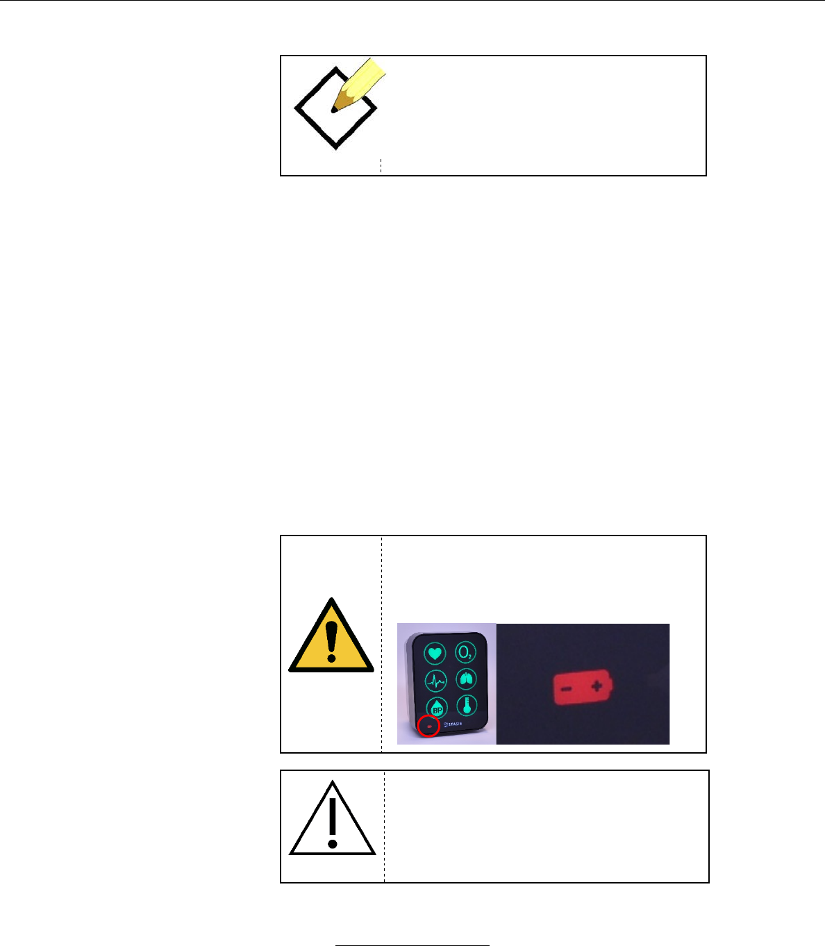
WARNING
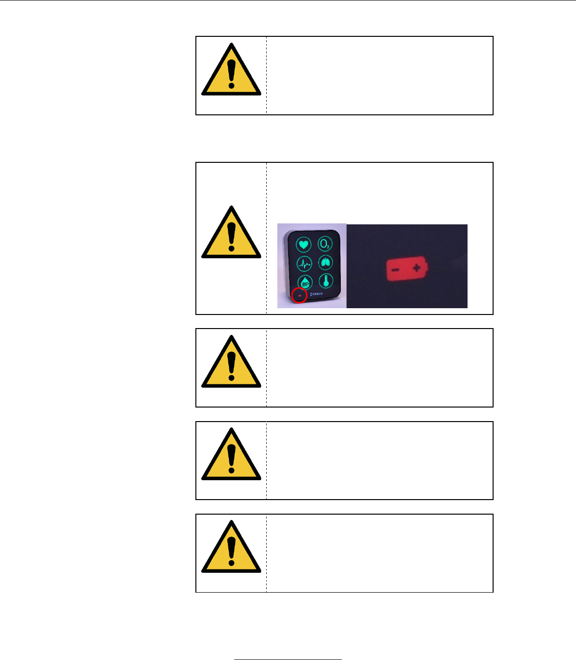
When the Battery level is critically low and
has 5 minutes or less of life remaining, the
Battery icon will flash red and an audible
alarm will sound.
WARNING
To ensure patient safety, do not place the
SMS in any position that might cause it to fall
on the patient.
WARNING
Ensure that the speaker is clear of any
obstructions. Failure to do so could result in
an inaudible alarm tone.
WARNING
Do not use the SMS in a MRI suite.
Stasis Monitoring System User’s Guide
Page 9
GPD-0001 Rev B
WARNING
Do not use the SMS to monitor a patient that
is being operated on with HF surgical
equipment.
WARNING
Explosion Hazard. Do not use the SMS in
the presence of flammable anesthetics or
gases.
WARNING
Vital sign readings may be affected by certain
environmental conditions. Refer to the
appropriate sections of this manual for
specific environmental safety information.
WARNING
Ensure that cable routing is conducted in a
manner which will reduce the possibility of
patient entanglement or strangulation.
WARNING
The conductive parts of the ECG electrodes
should not contact other conductive surfaces,
or earth ground, at any time.
WARNING
Do not lift the SMS by sensor/cuff cables or
power cord. This will protect the patient from
the possibility that such actions could result in
the SMS falling on the patient.
Stasis Monitoring System User’s Guide
Page 10
GPD-0001 Rev B
WARNING
Do not lift the SMS by sensor/cuff cables or
power cord as damaged cabling may cause
inaccurate performance or device failure.
WARNING
Do not plug or unplug the AC adapter with
wet hands.
WARNING
Do not plug or unplug the AC adapter if the
system is wet (as could be the case after
cleaning).
WARNING
Do not clean the unit while the power is on
and if the AC adapter is connected to the
SMS.
WARNING
Do not connect the SMS to an electrical outlet
that is controlled by a wall switch as the SMS
may be accidentally turned off.
WARNING
Ensure that all sensors/cuffs are connected to
the patient properly.

Stasis Monitoring System User’s Guide
Page 11
GPD-0001 Rev B
WARNING
Do not immerse or wet the SpO2 sensor.
WARNING
Failure to cover the SMS SpO2 sensor with
opaque light conditions may result in
inaccurate measurements.
WARNING
Inappropriate application or duration of SpO2
or ECG sensors may result in tissue damage.
Inspect the SpO2 and ECG sensor sites as
directed in the SpO2 and ECG sensor
directions for use.
WARNING
Only use the same type of ECG electrodes
for the various sites on the body. Mixing
ECG electrode types can adversely affect
ECG measurements.
WARNING
Make certain that the NIBP cuff tube is not
bent during inflation and deflation, particularly
after a change in patient body position.
WARNING
Do not wrap the cuff on the following parts of
the patient.
• An upper arm on which an SpO2 sensor, IBP
catheter, or other monitor sensor is connected.
• An upper arm on which an intravenous drip or
blood transfusion is being performed.
• An upper arm with a shunt for hemodialysis.
Stasis Monitoring System User’s Guide
Page 12
GPD-0001 Rev B
WARNING
If the NIBP cuff, SpO2 sensor or temperature
sensor is used on a patient with an infection,
it is the responsibility of the healthcare
professionals to treat the cuff or sensors as
medical waste or consider if appropriate
sanitizing cuff or sensors before reuse.
WARNING
Do not use sensors/cuffs prior that appear to
be damaged as damaged sensors/duffs may
cause inaccurate performance or device
failure.
WARNING
Ensure that all sensors/cuffs are connected to
the SMS properly.
WARNING
When the SMS monitor alarms or alerts, it is
the responsibility of healthcare professionals
to review patient condition clinically before
conducting interventional measures.
WARNING
It is the responsibility of healthcare
professionals to manage the alarm
notification settings for their patients.
WARNING
Do not operate the SMS in an environment
with high O2 levels.
Stasis Monitoring System User’s Guide
Page 13
GPD-0001 Rev B
WARNING
Impedance pneumography for the
determination of Respiration Rate (RESP) is
not recommended for use in the presence of
mechanically induced high frequency
ventilation.
WARNING
The SMS has not been tested for use on
neonatal or pediatric patients under the age
of 21 years.
WARNING
The SMS has been designed to pair a single
monitor to a single tablet during patient
monitoring activities. It is not possible to view
patient data from more than one SMS on a
single tablet.
WARNING
Do not use the same SMS to measure the
NIBP of one patient while it is connected
simultaneously to another patient.
WARNING
Do not use the SMS on a patient with an
Intra-Aortic Balloon Pump (IABP), or a Left
Ventricular Assist Device (LVAD). The
Monitor requires an unperturbed arterial pulse
waveform for non-invasive blood pressure
calculations. IABP and LVAD perturb the
arterial pulse waveform.
WARNING
Do not use the SMS on a patient on cardio-
pulmonary bypass.
Stasis Monitoring System User’s Guide
Page 14
GPD-0001 Rev B
WARNING
Do not use the SMS on patient arm where the
use of a blood pressure cuff is
contraindicated.
WARNING
Do not use the SMS in a MRI Suite.
WARNING
The SMS has been designed to pair a single
monitor to a single tablet during patient
monitoring activities. It is not possible to view
patient data from more than one SMS on a
single tablet.
WARNING
The effectiveness of the SMS’s blood
pressure monitoring has not been established
in the presence of any dysrhythmias.
WARNING
Should the SMS monitor lose Bluetooth
connection to the SMS tablet, the distributed
alarm function will not function. The tablet
must not be relied upon to annunciate alarms.
WARNING
When an alarm notification occurs, it is an indicator
that the patient needs increased attention.
Therefore, it is important for clinical personnel
to pay particular attention to the patient. It is
the responsibility of the healthcare
professional to take appropriate clinical
actions, including physically check on the
patient if necessary, before enabling the
PAUSE ALARM function.
Stasis Monitoring System User’s Guide
Page 15
GPD-0001 Rev B
WARNING
If the user is uncertain about the accuracy of
any measurement, it is the responsibility of
healthcare professionals to check patient vital
signs by an alternative means if deemed
necessary and make certain that the sensors
and/or SMS is functioning properly.
WARNING
Do not spray, pour, or spill liquids into or onto
the Monitor unit, accessories, connectors,
buttons, or openings in the housing.
WARNING
Dispose of all electrical components
associated with the SMS in accordance with
local requirements and regulations.
WARNING
Always leave the SMS plugged in to a
hospital-grade AC power outlet when
possible.
B. Cautions Summary
CAUTION
All users should read this manual thoroughly.
An electronic version of the current copy of
this manual may be obtained by emailing:
contact@stasislabs.com
CAUTION
Medical personnel using the SMS must be
properly trained in the use of the device.
Stasis Monitoring System User’s Guide
Page 16
GPD-0001 Rev B
CAUTION
The user is responsible for exercising
appropriate protocols to act in accordance with
HIPAA regulations with regards to personnel
access to the computer operating the SLMS or
when sharing patient-specific information.
CAUTION
Federal Law (USA) restricts this device to
sale by or on an order of a physician.
CAUTION
Check the wall power source to make certain
that it is providing 110VAC power.
CAUTION
If the device has not been used for an
extended period of time, verify that it operates
normally and safely before use.
CAUTION
Do not subject the SMS unit to mechanical
shocks, such as dropping the unit on the
floor.
CAUTION
Using the Tablet in high ambient light
conditions may affect the ability to read the
values correctly.
CAUTION
A displayed NIBP value that is outside of the
measurement range of 60-230 mmHg for
systolic pressure and 40-130 mmHg for
diastolic pressure is not accurate and must
be verified.
Stasis Monitoring System User’s Guide
Page 17
GPD-0001 Rev B
CAUTION
Only use a GE DURA-CUF NIBP cuff with
this device.
CAUTION
Use the appropriate size NIBP cuff to ensure
correct measurements. If the NIBP cuff is too
large the measured blood pressure value
tends to be lower than the actual blood
pressure. If the NIBP cuff is too small the
measured blood pressure value tends to be
higher than the actual blood pressure.
CAUTION
NIBP measurements should be performed
with the cuff placed on the upper arm.
CAUTION
Make certain that the part of the cuff is
approximately the same elevation as the
heart. A difference of 10cm (4in) in height
may cause a variation in the measured blood
pressure value of up to 7-8mmHg.
CAUTION
If the NIBP cuff is wrapped over thick clothing
it could affect the accuracy of the measured
blood pressure.
CAUTION
If patient sleeve is rolled up in a manner
where it exerts pressure on the arm it could
affect the accuracy of the measured blood
pressure.
Stasis Monitoring System User’s Guide
Page 18
GPD-0001 Rev B
CAUTION
If the patient moves or talks during the blood
pressure measurement it could affect the
accuracy of the measured blood pressure.
CAUTION
Make certain that the pneumatic connector is
locked on the pneumatic nipple on the SMS
unit. If the pneumatic connection is not
secure it could affect the accuracy of the
readings.
CAUTION
Make certain that the cuffing tubing does not
have a heavy object resting on it and that it
has no kinks, as restrictions in air flow to the
cuff can affect the accuracy of the NIBP
readings.
CAUTION
Do not use the NIBP cuff if it is damaged or
has holes.
CAUTION
If you believe that your SMS is in need of
repair, contact your Stasis sales
representative for instructions on sending the
system to Stasis for diagnosis and repairs.
CAUTION
Installation of unauthorized software will
result in the voiding of the SMS service
agreement.
Stasis Monitoring System User’s Guide
Page 19
GPD-0001 Rev B
CAUTION
The SMS can be sanitized by wiping down
with a soap and water solution, 70% isopropyl
alcohol, or dilute glutaraldehyde solution.
CAUTION
Do not sterilize by autoclave, irradiation, or
gas sterilization methods.
C. Notes Summary
NOTE
Hospital use typically covers such areas as
general care floors, operating rooms, special
procedural areas, intensive and critical care
areas, or other regions within hospital or
hospital-type facilities. Hospital-type facilities
include physician-office-based facilities, sleep
labs, skilled nursing facilities, surgical centers,
sub-acute centers, dental clinics, or oral
surgeon clinics.
Intra-hospital transport includes transport of a
patient within the hospital or hospital-type facility.
Home Care use is defined as managed/used
by a lay person (parent or other similar non-
critical care giver) in the home environment.
Use with any particular patient requires the
selection of appropriate sensors as described
in this manual.
NOTE
The Stasis power supply cord has a two-
prong US power plug. If the user is using the
SMS device in an environment with a
different power source or outlet design, the
user will need to procure a converter.
Stasis Monitoring System User’s Guide
Page 20
GPD-0001 Rev B
NOTE
Battery power life may be affected by certain
operational parameters including, but not
limited to:
• The frequency at which audible alarms are
sounded.
• The frequency at which NIBP
measurements are made.
NOTE
For the Sync to occur successfully between
the SMS and the Tablet there must be a valid
Bluetooth connection.
NOTE
For the Sync to occur successfully between
the SMS and the Tablet a patient must have
been selected or admitted on the Tablet.
NOTE
Place the SpO2 sensor on the finger in a
manner which results in the molded imprint of
the finger and nail is on the same side of the
finger as the nail.
NOTE
If there are no SMS systems within the same
Bluetooth range, the screen will prompt the
user to RETRY CONNECTION.
Stasis Monitoring System User’s Guide
Page 21
GPD-0001 Rev B
NOTE
The PAUSE ALARM button will only
illuminate when an alarm condition exists.
NOTE
Any displayed ECG alarms are based on a
rate-based detection algorithms, not a
waveform-based analysis
NOTE
Field strengths from fixed transmitters, such as
base stations for radio (cellular/cordless)
telephones, WIFI-enabled devices, and land
mobile radios; amateur radios; AM and FM radio
broadcast; and TV broadcast, and WIFI
transmission cannot be predicted theoretically with
survey accuracy. To assess the electromagnetic
environment due to fixed RF transmitters, an
electromagnetic site survey should be considered.
If the measured field strength in the location in
which the SMS is used exceeds the applicable RF
compliance level described in this section, the
SMS should be observed to verify normal
operation. If abnormal performance is observed,
additional measures may be necessary, such as
re-orienting or relocating the SMS.
NOTE
These guidelines may not apply in all
situations. Electromagnetic propagation is
affected by absorption and reflection from
structures, objects, and people.
Stasis Monitoring System User’s Guide
Page 22
GPD-0001 Rev B
NOTE
The SMS has an IP rating of IP22. This
means it is protected from intrusion by a large
part of the body such as a hand (but no
protection from deliberate access), and from
solid objects greater than 50mm in diameter.
It is also protected from vertically dripping
water when the enclosure is tilted at an angle
of up to 15 degrees from its normal position.
VII. USE CONSIDERATIONS
WARNING
Before using the SMS carefully read this
user’s guide, including all warnings, cautions,
and instructions.
WARNING
The SMS is intended for patient monitoring.
It must be used by healthcare professionals
in conjunction with the assessment of clinical
signs and symptoms to determine when
clinical action, or inaction, is warranted.
WARNING
The use of accessories, sensors, cuffs, and
cables other than those specified may result
in increased emissions and/or decreased
emission immunity and may result in
inaccurate measurements.
WARNING
Do not operate the SMS in an environment
with high O2 levels.
WARNING
It is the responsibility of healthcare
professionals to manage the alarm
notification settings for their patients.
Stasis Monitoring System User’s Guide
Page 23
GPD-0001 Rev B
WARNING
Impedance pneumography for the
determination of Respiration Rate (RESP) is
not recommended for use in the presence of
mechanically induced high frequency
ventilation.
WARNING
The SMS has not been tested for use on
neonatal or pediatric patients under the age
of 21 years.
WARNING
The SMS has been designed to pair a single
monitor to a single tablet during patient
monitoring activities. It is not possible to view
patient data from more than one SMS at a
time on a single tablet.
WARNING
Do not use the same SMS to measure the
NIBP of one patient while it is connected
simultaneously to another patient.
WARNING
Do not use the SMS on a patient with an
Intra-Aortic Balloon Pump (IABP), or a Left
Ventricular Assist Device (LVAD). The
Monitor requires an unperturbed arterial pulse
waveform for non-invasive blood pressure
calculations. IABP and LVAD perturb the
arterial pulse waveform.
WARNING
Do not use the SMS on a patient on cardio-
pulmonary bypass.
Stasis Monitoring System User’s Guide
Page 24
GPD-0001 Rev B
WARNING
Do not use the SMS on patient arm where the
use of a blood pressure cuff is
contraindicated.
WARNING
Do not use the SMS in a MRI Suite.
WARNING
The effectiveness of the SMS’s blood
pressure monitoring has not been established
in the presence of any dysrhythmias.
CAUTION
Medical personnel using the SMS must be
properly trained in the use of the device
CAUTION
The user is responsible for exercising
appropriate protocols to act in accordance with
HIPAA regulations with regard to personnel
access to the computer operating the SLMS or
when sharing patient-specific information.
A. INSTALLATION
1. Installation instructions:
a. The Stasis Monitoring System comes in 5 packages:
i. Stand Base and Hooks
ii. Stand Poles
iii. Stasis Monitor
iv. Stasis Sensors
Stasis Monitoring System User’s Guide
Page 25
GPD-0001 Rev B
v. Stasis Tablet
b. The first step in installing the Stasis Monitoring 3System is
assembling the stand.
i. Remove the stand base, bottom pole, top pole, cable
management hooks, and tablet cradle (if provided) from
the packaging.
ii. Attach the larger bottom pole to the stand base using the
single provided screw and set the stand upright.
iii. Slide the smaller top pole into the bottom pole, with the
threaded hole in the top pole towards the top.
iv. Slide the cable management hooks and tablet cradle (if
provided) on to the top pole.
v. Attach the monitor bracket to the top pole using the
single provided screw.
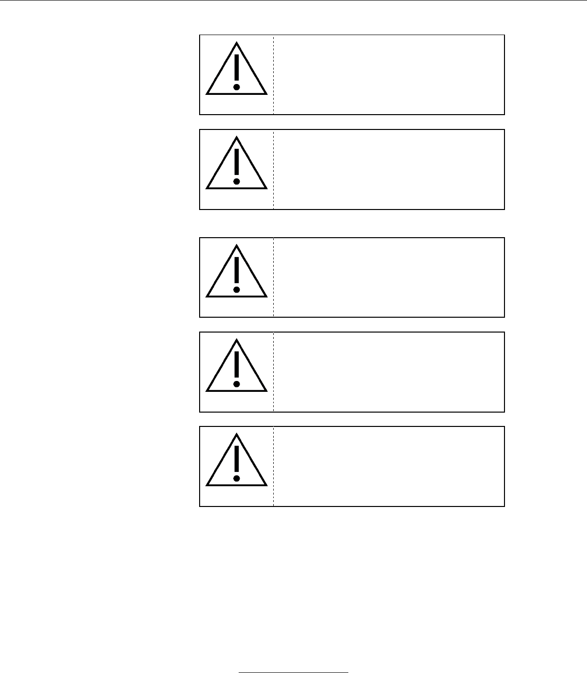
c. With the stand assembled, attach the Stasis Monitor to the
stand using the screw provided in the back of the Stasis
Monitor.
d. Connect the 4 sensors to the Stasis Monitor and loop the
sensor cables and hose around the cable management hooks.
e. Plug the power supply into a hospital-grade power outlet and
connect the barrel connector to the rear of the Stasis Monitor.
f. Place the Stasis Monitoring System in the location where it is
to be used. The Stasis Monitoring System is now ready for
use.
2. Considerations
CAUTION
Medical personnel using the SMS must be
properly trained in the use of the device.
CAUTION
All users should read this manual thoroughly.
An electronic version of the current copy of
this manual may be obtained by emailing:
contact@stasislabs.com
Stasis Monitoring System User’s Guide
Page 26
GPD-0001 Rev B
CAUTION
The user is responsible for exercising
appropriate protocols to act in accordance
with HIPAA regulations with regard to
personnel access to the computer operating
the SLMS or when sharing patient-specific
information.
LATEX ALLERGIES – No components made with
natural rubber latex are used in the components
that come in patient tissue contact!!
a. The operator position for this system is assumed to be adjacent
to the Stasis Monitoring System at the patient bedside.
B. Service
1. Troubleshooting and service procedures on the software or hardware
components may only be performed by, or under the direct
supervision of, Stasis-authorized personnel or agents.
2. Service Contact Information: contact@stasislabs.com
Stasis Monitoring System User’s Guide
Page 27
GPD-0001 Rev B
VIII. SYSTEM SET-UP
A. Components
WARNING
Only use the accessories, sensors, cuffs, and
cables described below with the SMS.
1. Stasis Monitor
a. Physical Characteristics
i. Size: 13.3cm(T) X 10.3cm(W) X 7.2cm(D)*
[5.38”(T) X 4.07”(W) X 3.88”(D)*]
* D (depth) does not include the protrusion of the
sensor connectors in the rear nor the room required
for sensor cables.
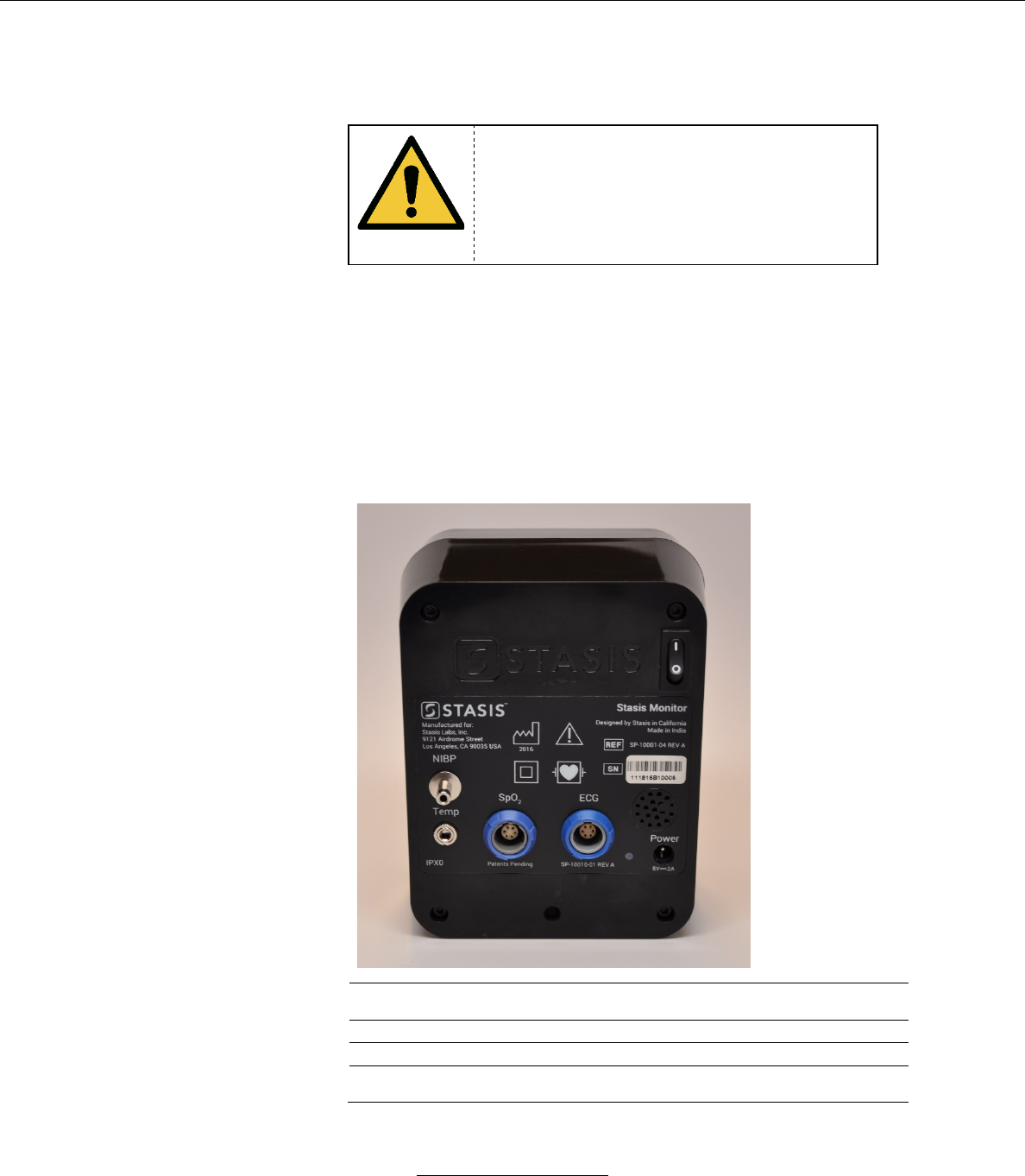
b. Back Panel
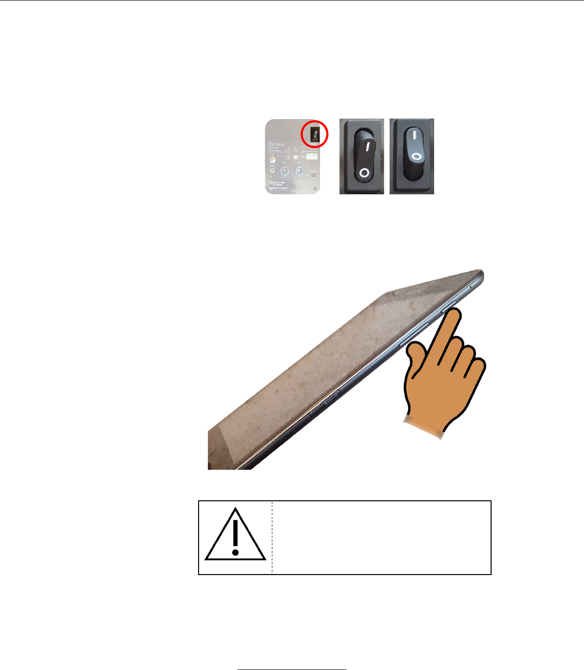
1
Power on/off switch
Rocker switch. Rock to “1” to power
on and rock to “0” to power off.
2
NIBP connector
Connects the NIBP cuff to the SMS
3
ECG connector
Connects the ECG leads to the SMS
4
Temperature connector
Connects the temperature sensor to
the SMS
1
2
3
4
6
5
Stasis Monitoring System User’s Guide
Page 28
GPD-0001 Rev B
5
DC power adaptor plug
Connects the AC adapter to wall
power source
6
SpO2 sensor connector
Connects the SpO2 sensor to the
SMS
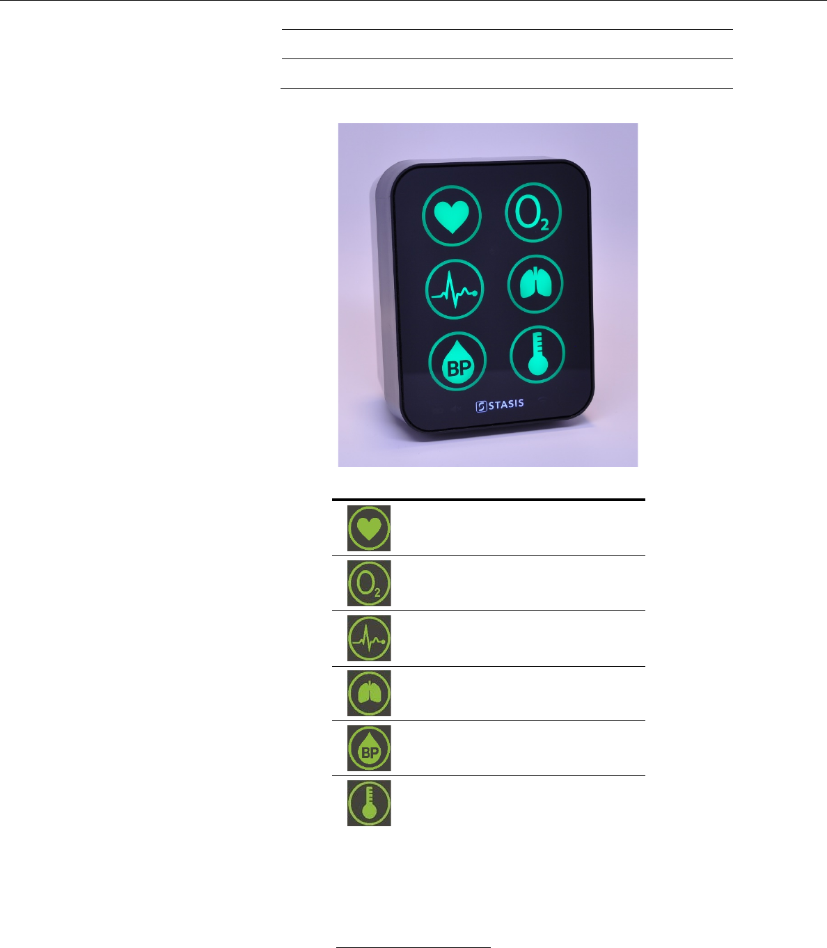
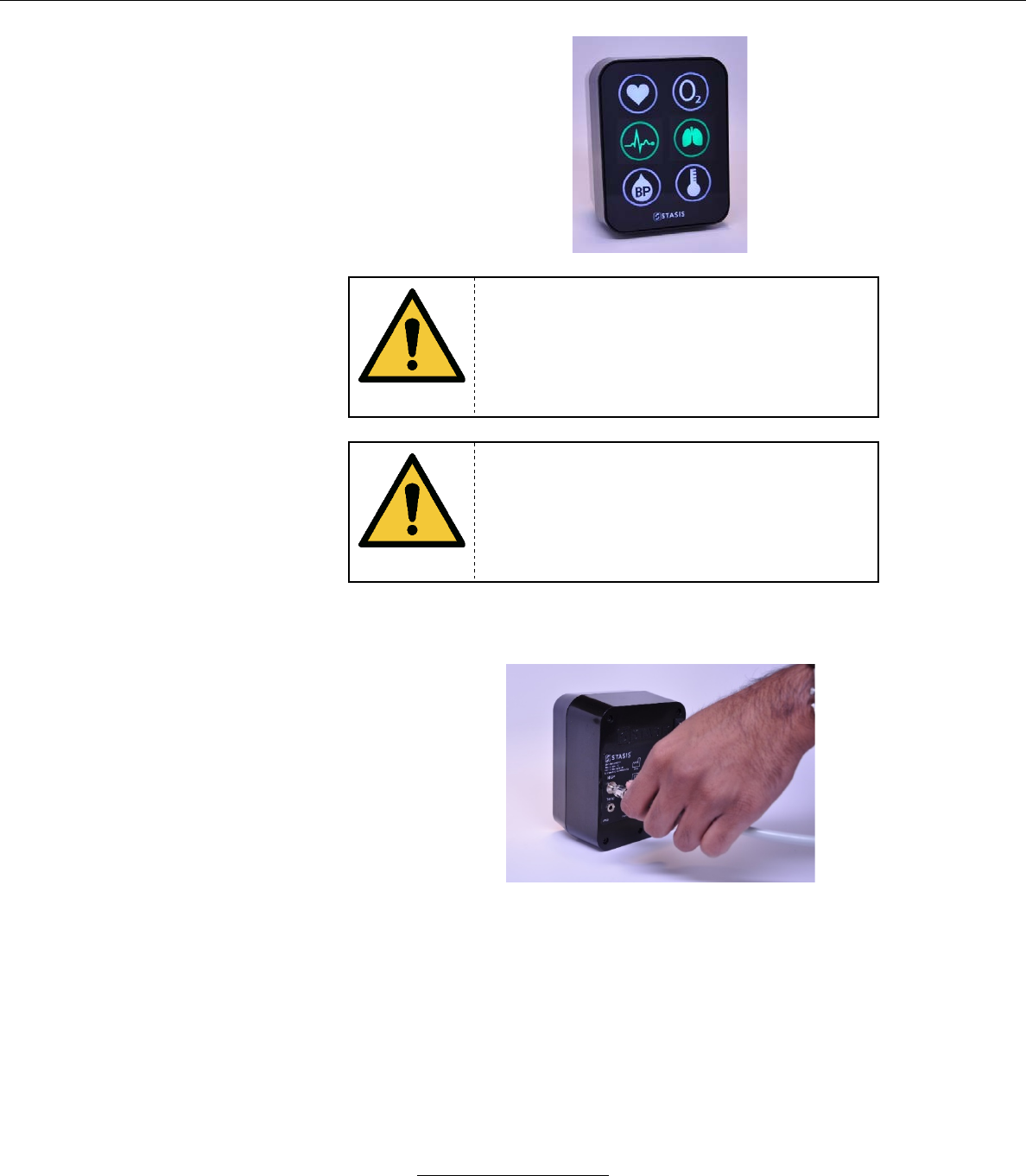
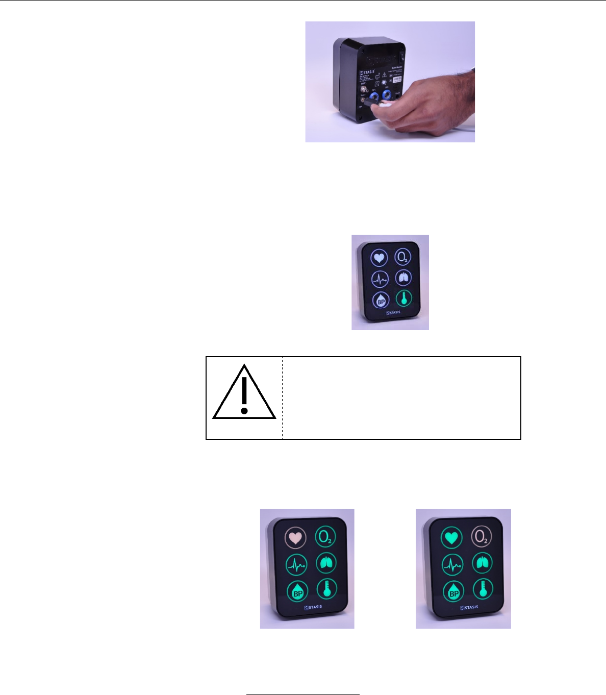
c. Front Panel
Vital Signs Indicators
Heart Rate (HR)
(sensor connected when illuminated)
Peripheral Oxygen Saturation (SpO2)
(sensor connected when illuminated)
Electrocardiogram (ECG)
(electrodes connected when
illuminated)
Respiration Rate (Resp)
(sensor connected when illuminated)
Blood Pressure (BP)
(cuff connected when illuminated)
Temperature (Temp)
(sensor connected when illuminated)
Stasis Monitoring System User’s Guide
Page 29
GPD-0001 Rev B
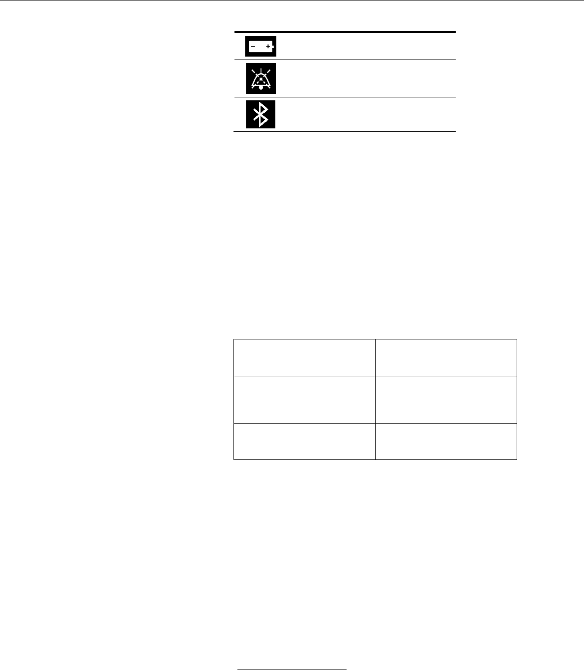
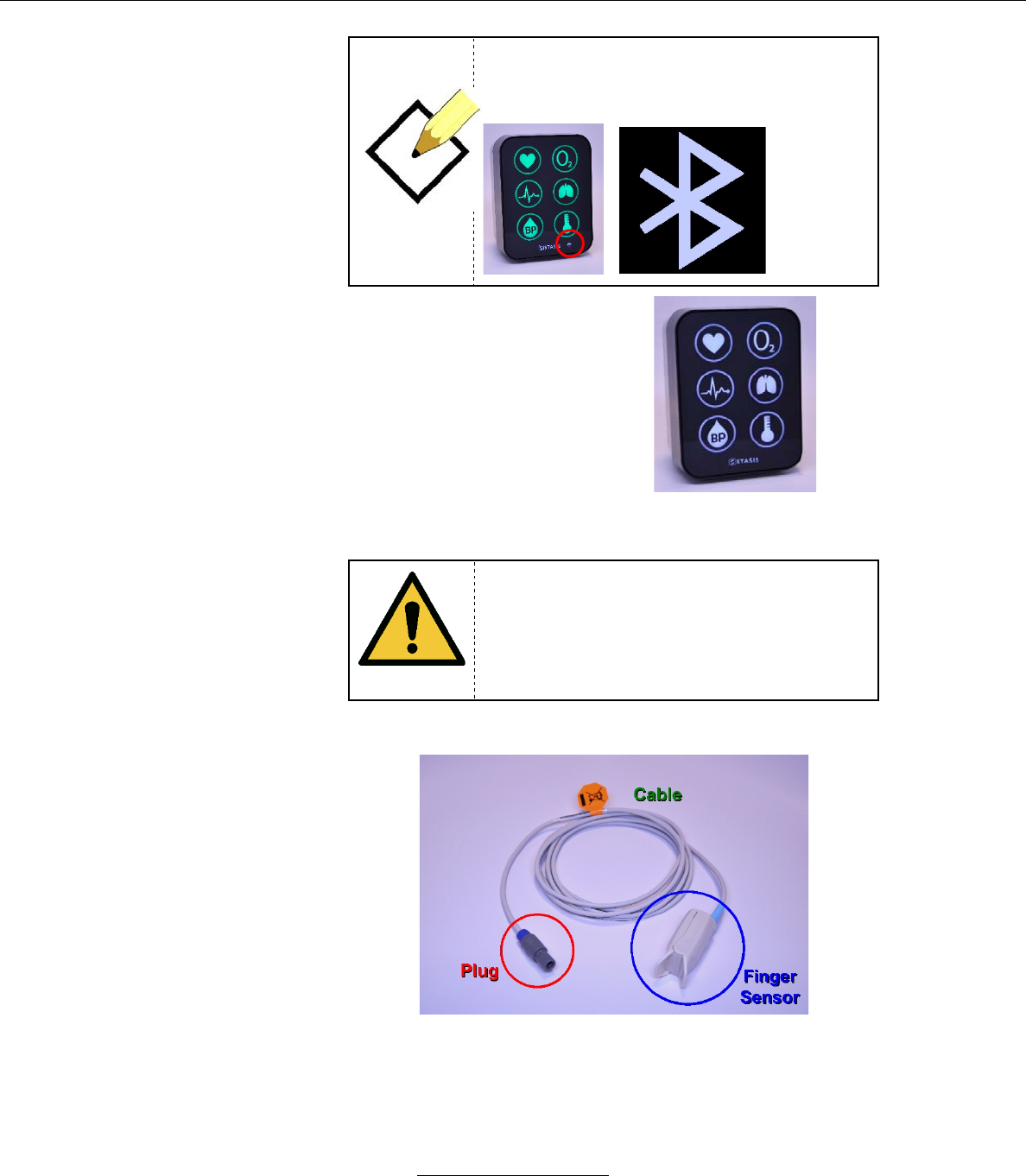
System Status Indicators (Next to Stasis Logo)
Battery (monitor operating on battery
power when illuminated)
Alarm Audio Paused (audible alarm is
disabled when illuminated)
Bluetooth (Bluetooth connection
between monitor and tablet is active
when illuminated)
i. Key Features
i-a. SpO2 (indicated by O2 symbol) and Heart
Rate (indicated by heart symbol) sensor
i-b. ECG (indicated by ECG waveform
symbol) and respiration rate (indicated by
lung symbol) sensor
i-c. Temperature (indicated by thermometer
symbol)
i-d. NIBP Monitoring (indicated by BP symbol)
Motion Stop Function
When body movement is
detected, the device stops
inflation for 5 seconds
Irregular Pulse Indicator
Helps identify changes in heart
rate, rhythm, or pulse which may
be caused by heart disease or
other serious health issues.
Inflation Pressure Settings
Initial inflation pressure is 140
mmHg, max inflation pressure is
300 mmHg
2. Samsung Galaxy Tab A 8” Tablet Console
a. Specifications:
i. 8” display
ii. Dimensions: 8.20” x 5.43” x 0.29”
iii. Android 5.0 or above
iv. 1.2 GHz quad-core processor
v. 802.11 a/b/g/n and Bluetooth 4.1 capability
vi. 1.5 GB RAM
Stasis Monitoring System User’s Guide
Page 30
GPD-0001 Rev B
vii. 16GB memory
b. Power ON/OFF
c. Interactive Touch Screen
i. Vital signs Indicators
3. Accessories
WARNING
The protection of the Stasis Monitor against
the effects of discharge of a cardiac
defibrillator depends on using only the
accessories described in this user manual.
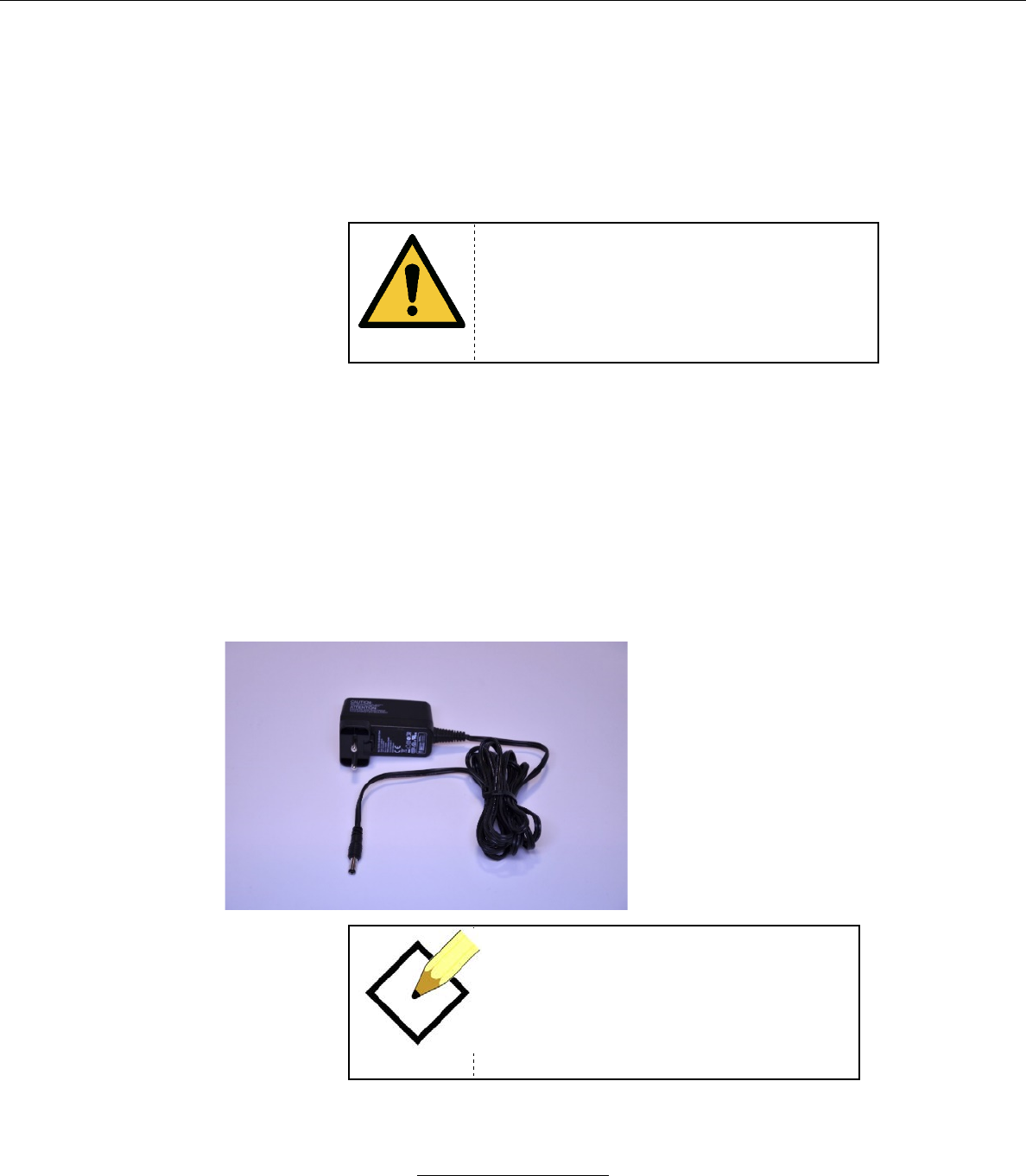
a. Friwo Power Supply
Type: FW8000M/05
Part Number: 1899240
Input Voltage: 100-240 V AC, 50-60 Hz
Nominal Output Voltage: 5 V DC
Nominal Output Current: 2200 mA
NOTE
The Stasis power supply cord is intended
to be plugged into a standard Type A
hospital plug. If the user is using the SMS
device in an environment with a different
power source or outlet design, the user will
need to procure a converter.
Stasis Monitoring System User’s Guide
Page 31
GPD-0001 Rev B
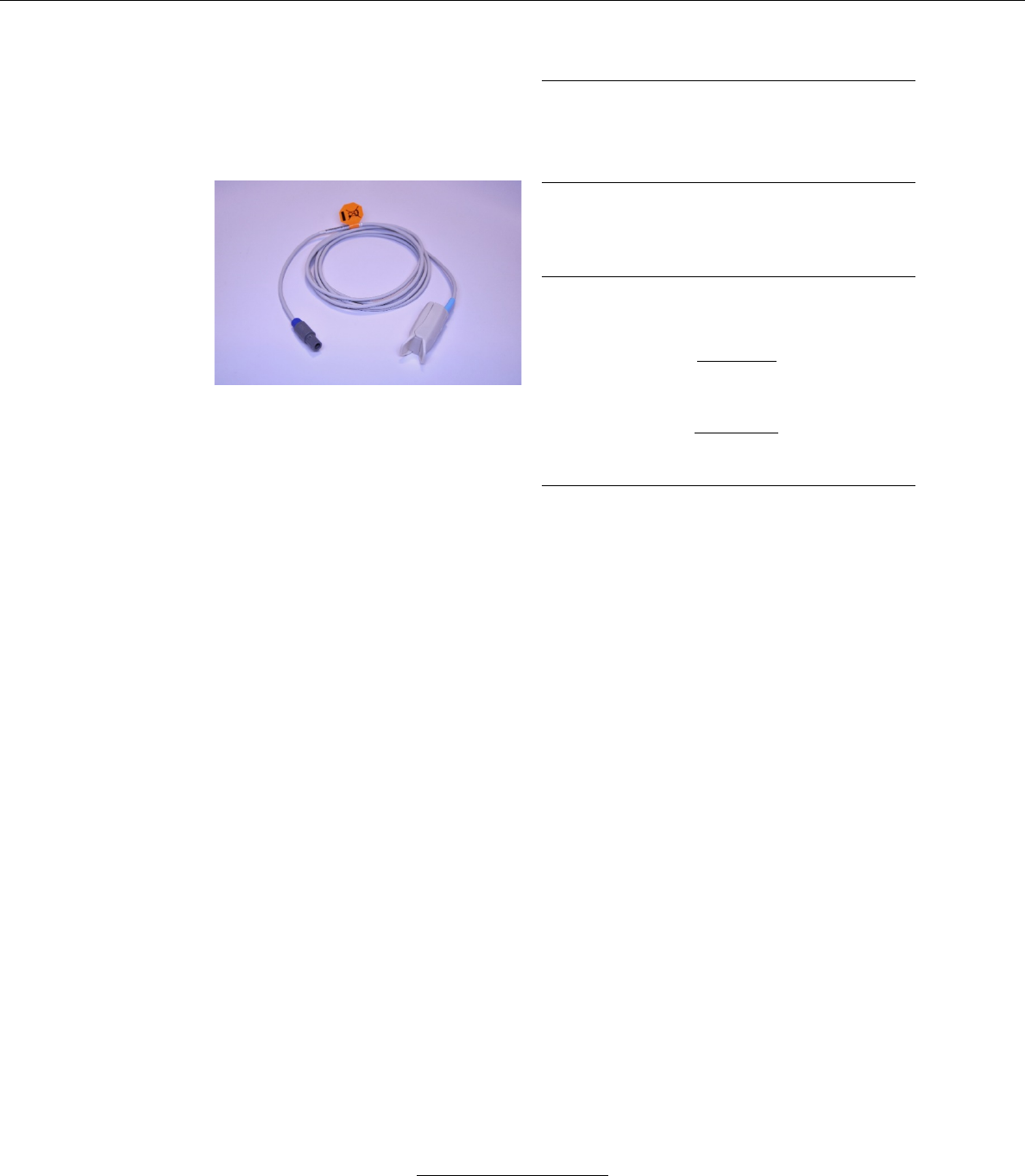
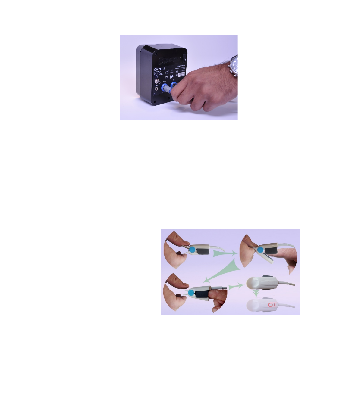
b. Unimed SpO2 Sensor (Model # U410-147)
Model # U410-147
Key Features
Adult Only
Greater than 40 kg
Measurement Range
SpO2
70% to 100%
Heart Rate
20 to 250 bpm
Perfusion Range
0.3% to 20%
Accuracy
Saturation
Adult1
70-100% +/- 2 digits
Low Perfusion2
70-100% +/- 2 digits
Heart Rate
Adult1
20-250 bpm +/- 3 digits
Low Perfusion2
20-250 bpm +/- 3 digits
1 Saturation accuracy may vary on sensor type used. Adult specifications are detailed in the IFU for the
particular sensor used.
2 Specification applies to monitor (SMS) performance.
Data Averaging: Display value is a moving average of the last 5 readings from the pulse
oximeter, which are taken at 60 Hz.
Data Update Period: Every 2 seconds
Alarm Condition Delay: 80 ms
Alarm Signal Generation Delay: 10 s
Range of peak wavelengths: 657-663 nm
Maximum optical output power: 2.0 mW
This information about the optical output and wavelength range of the SpO2 probe can
be especially useful to clinicians.
The Unimed U410-147 is the only pulse oximeter probe that is validated and tested for
compliance with ISO 80601-2-61 with the SMS. Do not use with any probe cable
extenders.
If the signal from the SpO2 Sensor is not sufficient to derive a reading, the tablet display
shows “Pulse Ox Not Connected” in the area where the waveform is typically displayed.
This serves as the signal inadequacy indicator.
The SpO2 waveform is normalized on the tablet display.
Stasis Monitoring System User’s Guide
Page 32
GPD-0001 Rev B
The pulse oximeter is calibrated to display functional oxygen saturation.
The accuracy of the pulse oximeter was validated against arterial blood sample
references from human subjects measured with a CO-oximeter.
A functional tester cannot be used to assess the accuracy of the pulse oximeter probe or
the accuracy of the Stasis Monitor’s pulse oximetry.
Do not leave the SpO2 sensor on a patient for more than 8 hours at a time before
inspecting the finger with the sensor for any potential injury.
The SpO2 sensor and the SMS have been validated and tested for compliance with ISO
80601-2-61.
The responsible organization can verify the functionality (but not the accuracy) of the
SpO2 sensor with a functional tester. A functional tester such as the Pronk Technologies
OX-1 OxSim Optical SpO2 Pulse Oximeter Simulator (any software version) is suitable
for this purpose. Refer to the operator’s manual of the functional tester for details of how
to verify the functionality of the SpO2 sensor.
SpO2 measurement can be adversely affected by the presence of dyshaemoglobins,
ambient light, electromagnetic interference, electrosurgical units, dysfunctional
hemoglobin, presence of certain dyes, and inappropriate positioning of the pulse
oximeter probe.
If the Stasis Monitor detects that the SpO2 or pulse rate value is potentially incorrect, the
Stasis Tablet will display the message “Reading may be unstable”.
The SpO2 sensor uses silicone for patient-contacting parts, which has no known toxicity
effects.
WARNING
This probe is only for use with the SMS. Do
not attempt to use this probe with other
monitoring systems.
WARNING
The responsible organization and the
operator must verify the compatibility of the
monitor and probe before use to avoid patient
injury.
Stasis Monitoring System User’s Guide
Page 33
GPD-0001 Rev B
WARNING
The misapplication of the pulse oximeter
probe with excessive pressure for extended
periods of time may cause a pressure injury
to the patient.
WARNING
The SpO2 sensor must only be used
continuously on a single finger for 8 hours
before inspecting the finger. If there is any
evidence of pressure injury or other damage
to the finger, move the sensor to a different
finger.
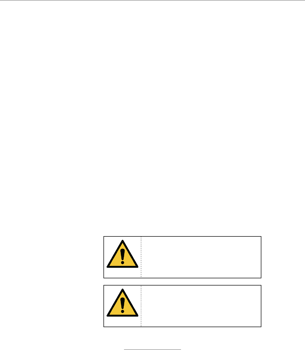
c. GE DURA-CUF NIBP Cuff, Adult Only
Adult Sizes Available (see GE DURA-
CUF catalog, only Adult cuffs can be
used)
Measurement Range:
Systolic: 60 – 230 mmHg
Diastolic: 40 – 130 mmHg
Pressure Precision: +/- 3 mmHg
Pressure Display Resolution: 1 mmHg
Pressure Measurement Variability:
Average Deviation: +/- 5 mmHg
Standard Deviation: +/- 8 mmHg
Maximum Inflation Pressure: 275 mmHg
d. NIBP Cuff Extension Tube (pictured above with NIBP cuff)
-NIBP Extension Tube for Edan M3A Vitals Monitor
-3 meters long
-Terminated with female metal bayonet connectors
Stasis Monitoring System User’s Guide
Page 34
GPD-0001 Rev B
WARNING
Taking blood pressure measurements too
frequently can cause injury to the patient due
to blood flow interference. Ensure that
circulation is not compromised during
repeated blood pressure measurements.
WARNING
Do not apply the blood pressure cuff over a
wound, as this may lead to additional patient
injury.
WARNING
Do not apply the blood pressure cuff to a limb
with intravascular access or an arterio-
venous shunt. Inflating the cuff may cause an
interruption in blood flow resulting in patient
injury.
WARNING
Do not apply the blood pressure cuff to a limb
on the side of the patient body where a
mastectomy was recently conducted.
WARNING
Pressurization of the blood pressure cuff can
temporarily cause loss of function of other
monitoring equipment that is being used on
the same limb as the cuff.
WARNING
Regularly check that the operation of the
automated sphygmomanometer does not
result in the prolonged impairment of patient
blood circulation.
Stasis Monitoring System User’s Guide
Page 35
GPD-0001 Rev B
WARNING
If a blood pressure measurement is
questionable, retake the measurement. If the
result is still questionable, use a different
method of measurement.
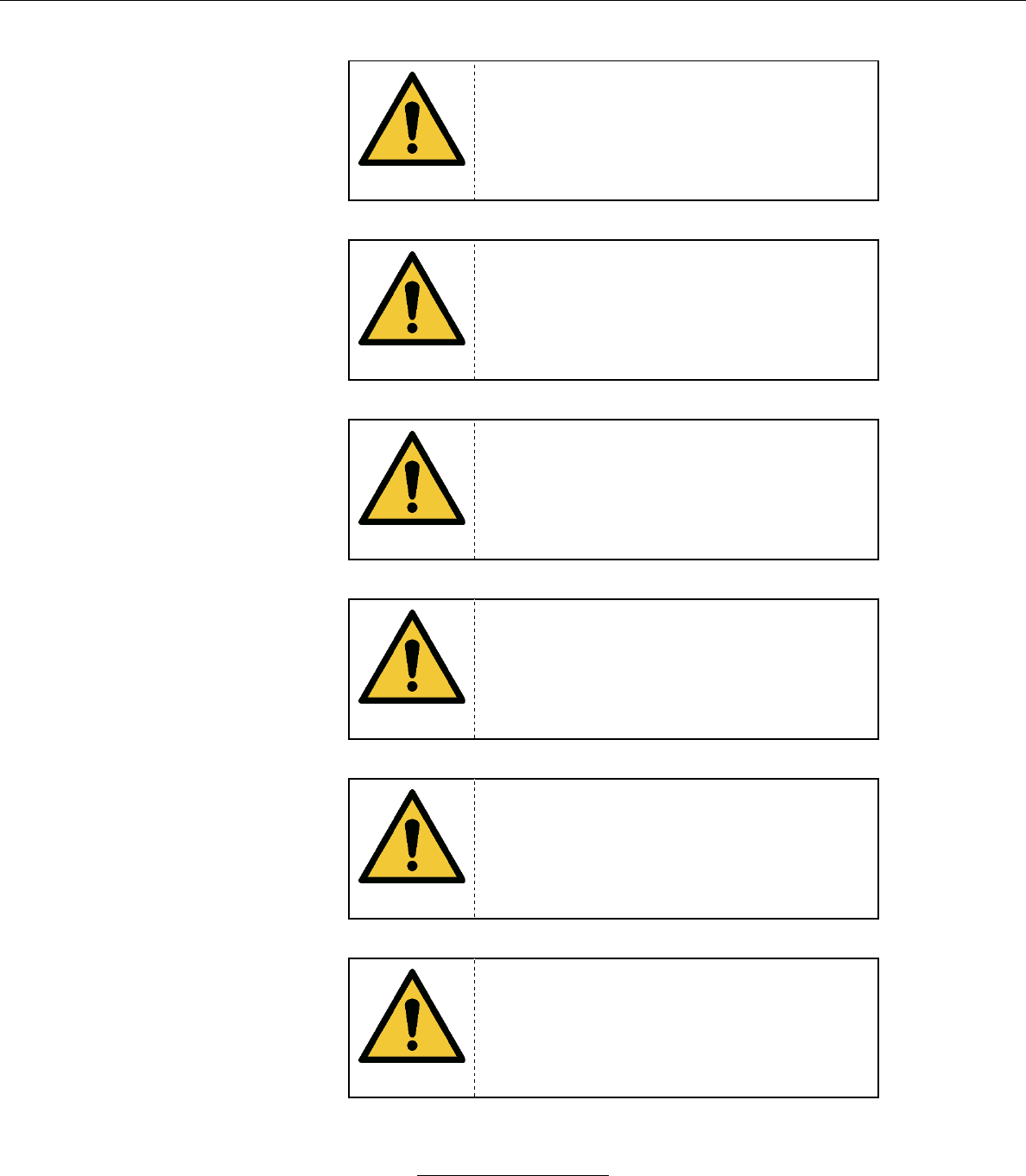
e. Med-Link EA021S3I ECG Cable
Respiration Rate Measurement:
Method: Impedance Pneumography
Range: 7-120 RPM
Resolution: 1 RPM
Accuracy: +/- 2 RPM
Key Features:
3 Leads
Defibrillation-protected
Heart Rate:
Range: 30 – 200 BPM
Accuracy: +/- 1% or 1 BPM,
whichever is greater
Resolution: 1 BPM
ECG and Respiration Rate Measurement Information
All Testing Conducted in Accordance with ANSI/AAMI EC13:2002
Available Time Base for ECG Display
25 mm/sec
Pacemaker
• The monitor detects and rejects
pacemaker impulses in accordance
with AAMI EC13:2002
• Performs heart rate calculations on a
patient with a pacemaker
• Will not recognize a pacemaker
impulse as a QRS
• Displays pacer markers on ECG
waveforms

Stasis Monitoring System User’s Guide
Page 36
GPD-0001 Rev B
Pacemaker Pulse Rejection Without
Overshoot
• Pacemaker pulse rejection range:
o Amplitude: -2 mV to 2 mV
o Pulse width: 0.1 ms to 2 ms
• Indicated Heart Rate:
o Ventricular Pacing:
§ Case (a): 0 BPM
§ Case (b): 60 BPM
§ Case (c): 30 BPM
o Atrial/Ventricular Pacing:
§ Case (a): 0 BPM
§ Case (b): 60 BPM
§ Case (c): 30 BPM
Pacemaker Pulse Rejection With
Overshoot
• Pacemaker pulse rejection range:
o Amplitude: -2 mV to 2 mV
o Pulse width: 0.1 ms to 2 ms
• Overshoot time: 0 ms to 4 ms
• Indicated Heart Rate:
o Ventricular Pacing:
§ Case (a): 0 BPM
§ Case (b): 60 BPM
§ Case (c): 30 BPM
o Atrial/Ventricular Pacing:
§ Case (a): 0 BPM
§ Case (b): 60 BPM
§ Case (c): 30 BPM
Defibrillation Response
• Defibrillation protected
• Displays heart rate measurement less
than 5 seconds after defibrillation
• Displays an ECG waveform less than
5 seconds after defibrillation
T-Wave Rejection
Rejects T-Waves up to 120% of QRS
amplitude
Heart Rate Averaging
Measured heart rate is a 15 second moving
average
Heart Rate Accuracy and Response
to Irregular Rhythm
Waveform A1: 80 BPM
Waveform A2: 60 BPM
Waveform A3: 120 BPM
Waveform A4: 92 BPM
Change in Heart Rate
80 BPM to 120 BPM: Less than 10 seconds
80 BPM to 40 BPM: Less than 10 seconds
Time to Alarm for Cardiac Standstill
Less than 10 seconds
Stasis Monitoring System User’s Guide
Page 37
GPD-0001 Rev B
Time to Alarm for Tachycardia
Figure B1:
• 1.0 x Gain: 6 seconds
• 2.0 x Gain: 8 seconds
• 0.5 x Gain: 6 seconds
Figure B2:
• 1.0 x Gain: 6 seconds
• 2.0 x Gain: 8 seconds
• 0.5 x Gain: 6 seconds
Input Impedance
>5 Mohms
Respiration Rate Detection Signal
Applied to Patient
32.5 kHz sine wave
0.08 V P-P
Lead-Off Detection Current
48.3 nA
WARNING
Do not use the SMS to monitor a patient that
is being operated on with HF surgical
equipment.
WARNING
Pacemaker Patients: Rate meters may
continue to count the pacemaker rate during
occurrences of cardiac arrest or some
arrhythmias. Do not rely entirely upon heart
rate meter alarm signals. Keep pacemaker
patients under close surveillance. See this
manual for disclosure of the pacemaker pulse
rejection capability of this instrument
WARNING
Do not use the SMS to monitor a patient that
is being operated on with HF surgical
equipment.
Stasis Monitoring System User’s Guide
Page 38
GPD-0001 Rev B
NOTE
Use the ECG cable only with 3M Red Dot
2560 Monitoring Electrodes.
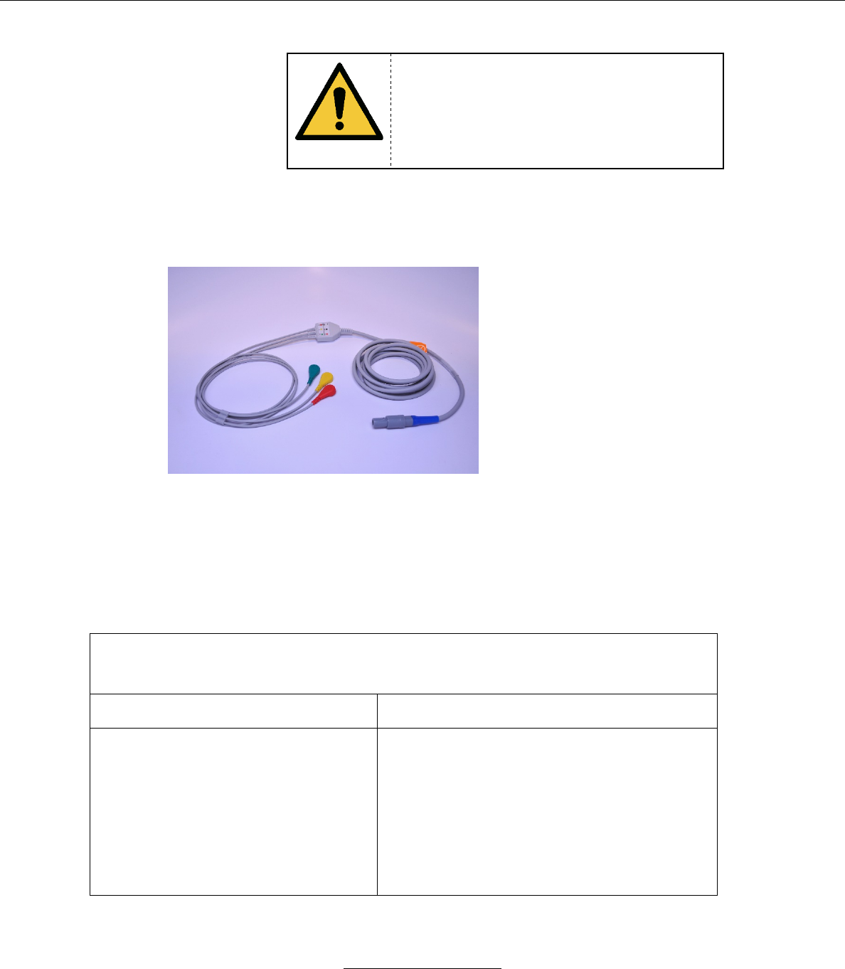
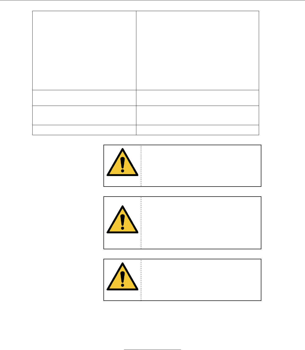
f. Unimed T2252-AS Temperature Sensor, Adult Only
The sensor must be used with the
included adapter (Monoprice part
number 7135) as shown in the above
image to connect with the Stasis
Monitor’s compact temperature port.
Key Features:
Skin temperature sensor intended to
be attached to an adult patient’s skin
in the axillary region with medical
tape. This is a direct mode
thermometer that displays the
measured temperature at the axillary
site.
Display Range: 30-45 °C
Accuracy Range: 10-50 °C
Resolution: 0.1 °C
Accuracy: +/- 0.2 °C
Recommended minimum
measurement time: 5 minutes
Measured time response:
35 to 37 °C: 59 seconds
35 to 33 °C: 32 seconds
NOTE
Do not leave the adapter connected to the
Stasis Monitor without the temperature
sensor attached to avoid the possibility of
accidental impact damage.
Stasis Monitoring System User’s Guide
Page 39
GPD-0001 Rev B
IX. SYSTEM USE
A. SMS placement
1. Place the SMS within 1m of the patient at the patient bedside.
WARNING
To ensure patient safety, do not place the
SMS in any position that might cause it to fall
on the patient.
WARNING
Disconnect all sensors/cuffs from the patient
during magnetic resonance imaging (MRI)
scanning. Induced current could potentially
cause burns.
WARNING
Explosion Hazard. Do not use the SMS in
the presence of flammable anesthetics or
gases.
WARNING
Vital sign readings may be affected by certain
environmental conditions. Refer to the
appropriate sections of this manual for
specific environmental safety information.
WARNING
Ensure that the speaker is clear of any
obstructions. Failure to do so could result in
an inaudible alarm tone.
WARNING
Remove the SMS from the vicinity of the
patient if he/she is in the same room as a
magnetic resonance imaging (MRI) scanning
device. The magnetic field of the MRI may
cause the system to fall on the patient.
Stasis Monitoring System User’s Guide
Page 40
GPD-0001 Rev B
WARNING
Ensure that cable routing is conducted in a
manner which will reduce the possibility of
patient entanglement or strangulation
WARNING
The conductive parts of the ECG electrodes
should not contact other conductive surfaces,
or earth ground, at any time.
WARNING
Do not lift the SMS by sensor/cuff cables or
power cord in order to protect the patient from
the possibility that such actions could result in
the SMS falling on the patient.
WARNING
Do not lift the SMS by sensor/cuff cables or
power cord as damaged cabling may cause
inaccurate performance or device failure.
CAUTION
Do not subject the SMS unit to mechanical
shocks, such as dropping the unit on the
floor.
B. Connecting the SMS to Power and Charging the Battery.
1. The SMS has an internal battery power source that may be used to power
the SMS when AC power is not available. A new, fully-charged monitor
may operate on its battery power source for at least 2 hours.
2. The SMS is intended to be plugged in to a power source at all times.
CAUTION
If the device has not been used for an
extended period of time, verify that it operates
normally and safely before use.
Stasis Monitoring System User’s Guide
Page 41
GPD-0001 Rev B
NOTE
Battery power life may be affected by certain
operational parameters including, but not
limited to:
• Frequency at which audible alarms are sounded.
• The frequency at which NIBP measurements
are made.
3. Charging the SMS Battery
a. Upon initial receipt of the SMS from Stasis, the SMS battery will
not be charged adequately to operate for proper operation.
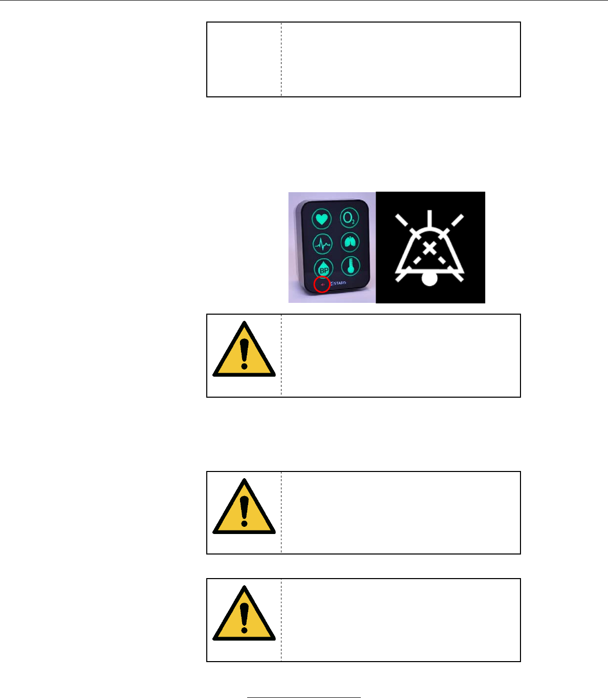
b. The SMS has a battery power indicator on the bottom left to
let the user know the battery status.
c. If the monitor is plugged in and fully charged, the battery
icon will be off.
d. If the monitor is plugged in and charging, the battery icon will
flash white.
e. If the monitor is unplugged and using battery power, the
battery icon will be illuminated in white.
f. If the monitor is unplugged and has a low battery, the battery
icon will be illuminated in cyan.
g. If the monitor is unplugged and has a critically low battery
the battery icon will flash red.
WARNING
When the Battery level is critically low, and
the system is in danger of shutting down, the
Battery icon turns red and flashes. An audible
alarm will sound as well.
CAUTION
Always leave the SMS connected to a power
supply whenever possible. The internal
battery is only intended as a backup power
source.
Stasis Monitoring System User’s Guide
Page 42
GPD-0001 Rev B
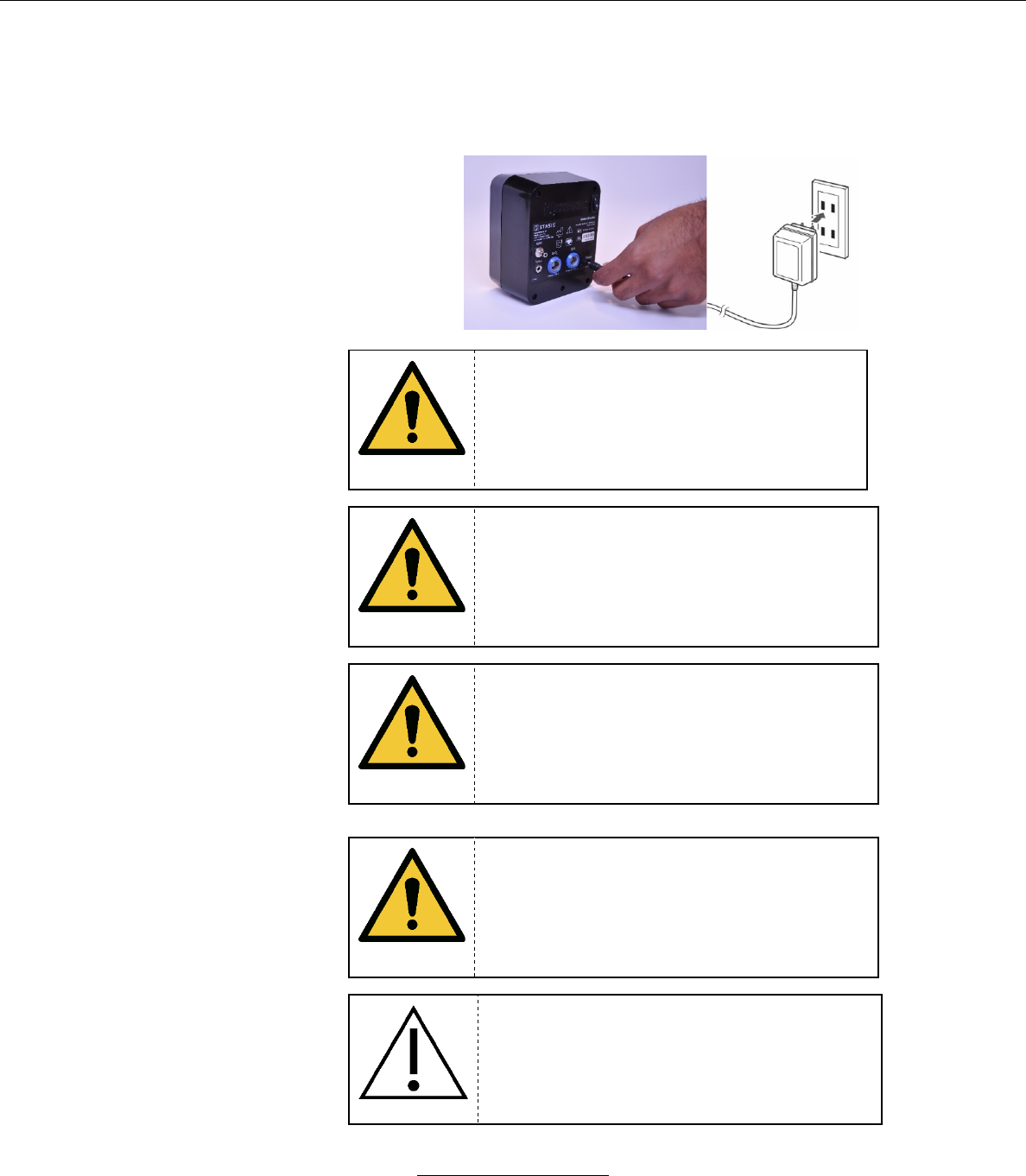
h. The SMS AC adapter is designed to convert wall current from
a Type A hospital grade wall outlet to 5VDC to charge the
system’s battery. To operate the system and charge the SMS
battery, connect the AC adapter to the DC connector on the
SMS and insert the wall plug in to the wall power outlet.
WARNING
Do not plug or unplug the AC adapter with
wet hands.
WARNING
Do not plug or unplug the AC adapter if the
system is wet (as could be the case after
cleaning).
WARNING
Do not clean the unit while the power is on
and if the AC adapter is connected to the
SMS.
WARNING
Do not connect the SMS to an electrical outlet
that is controlled by a wall switch as the SMS
may be accidentally turned off.
CAUTION
Check the wall power source to make certain
that it is providing 110VAC power.
Stasis Monitoring System User’s Guide
Page 43
GPD-0001 Rev B
i. The internal battery takes approximately 50 minutes to
charge from 0% to 90%.
C. Power the SMS device on
1. Press the rocker switch on the back from the “OFF” to the “ON” position
OFF ON
D. Power the Tablet on
1. Press, and hold down, the power button on the tablet.
CAUTION
Using the Tablet in high ambient light
conditions may affect the ability to read the
values correctly.
E. Configuring the Stasis Tablet Application
a. When the user first opens the Stasis Tablet Application, they will be prompted to
configure the HOSPITAL ADMINISTRATOR SETTINGS.
Stasis Monitoring System User’s Guide
Page 44
GPD-0001 Rev B
b. The user will be prompted to enter in Default Alarm Settings.
c. The user will be prompted to either Enable or Disable audio for low-priority
technical alarms.
d. The user will be prompted to configure Alarm Pause Times, which will be chosen
from when pausing active physiological alarms.
e. The user will be prompted to either allow or disallow the ability to use custom
Alarm Settings on each patient. If disallowed, only the hospital-configured Default
Alarm Settings will be used.
F.
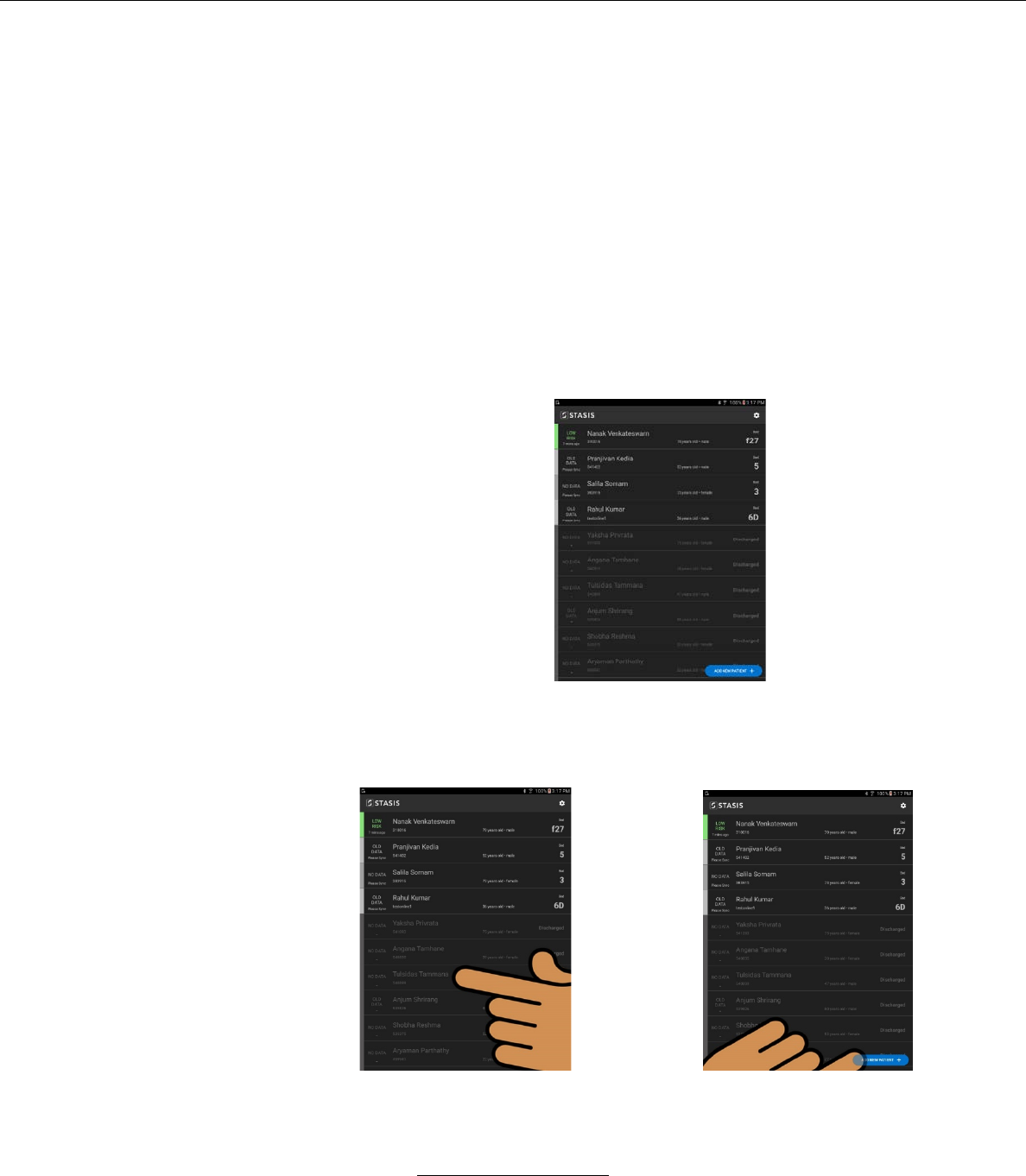
2. Admitting a Patient
a. After the STASIS icon is pressed the PATIENT SELECT /
ADD PATIENT screen will illuminate.
b. Select a patient by
…pressing patient name on the patient list
by pressing patient name
or
by pressing “Add New Patient”
On the patient list
icon
Stasis Monitoring System User’s Guide
Page 45
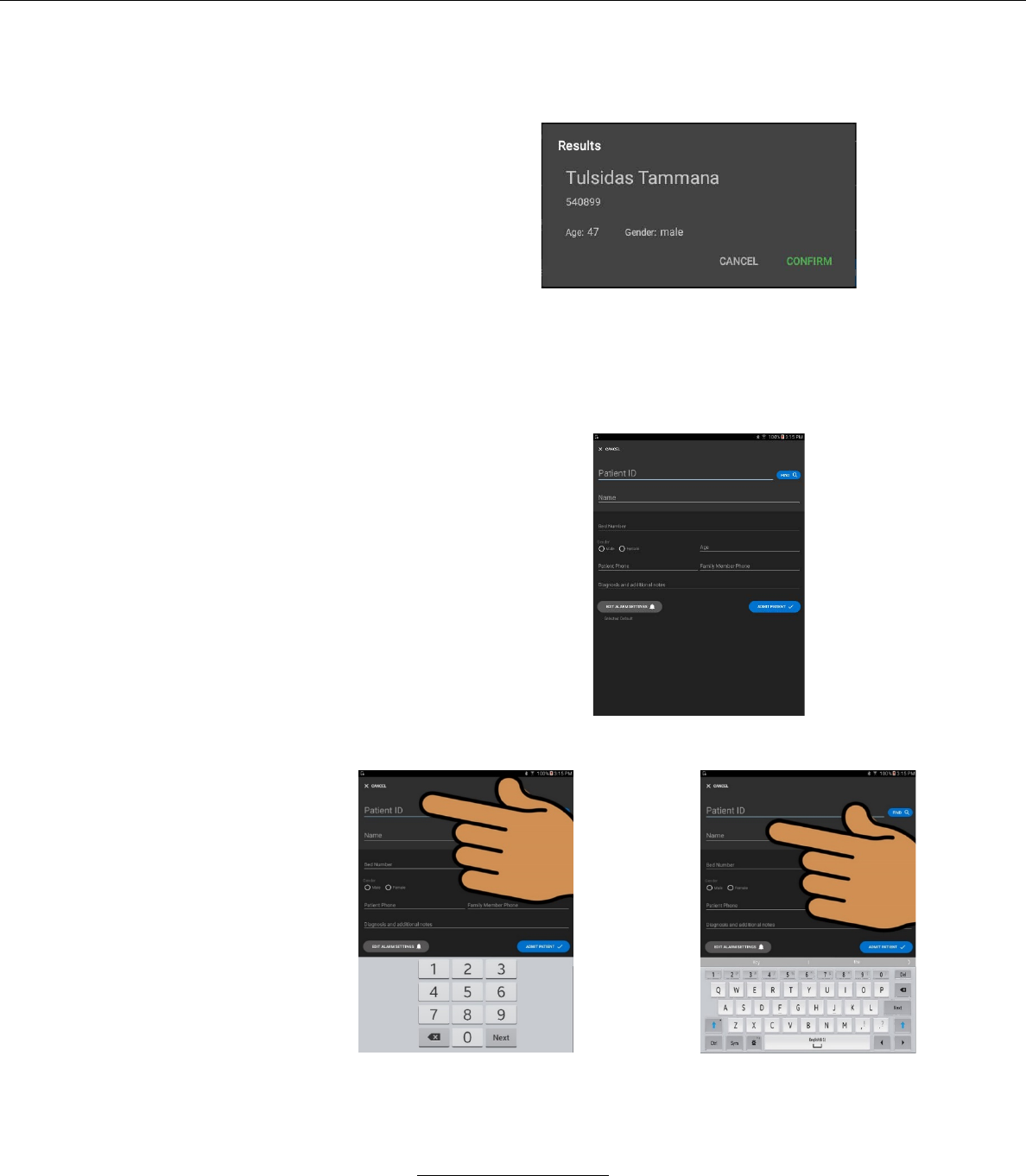
GPD-0001 Rev B
i. If the user chooses patient name from the supplied
list, the following window will pop up
– The user will be prompted to CONFIRM or
CANCEL the choice.
ii. To add a patient press the ADD A NEW PATIENT
button.
The following window will appear:
– The user may fill in the required information by
selecting the desired field.
the number pad displays when fields
requiring numeric values are
selected
or
The alpha-numeric keyboard
displays when fields requiring alpha
and numeric values are selected
Stasis Monitoring System User’s Guide
Page 46
GPD-0001 Rev B
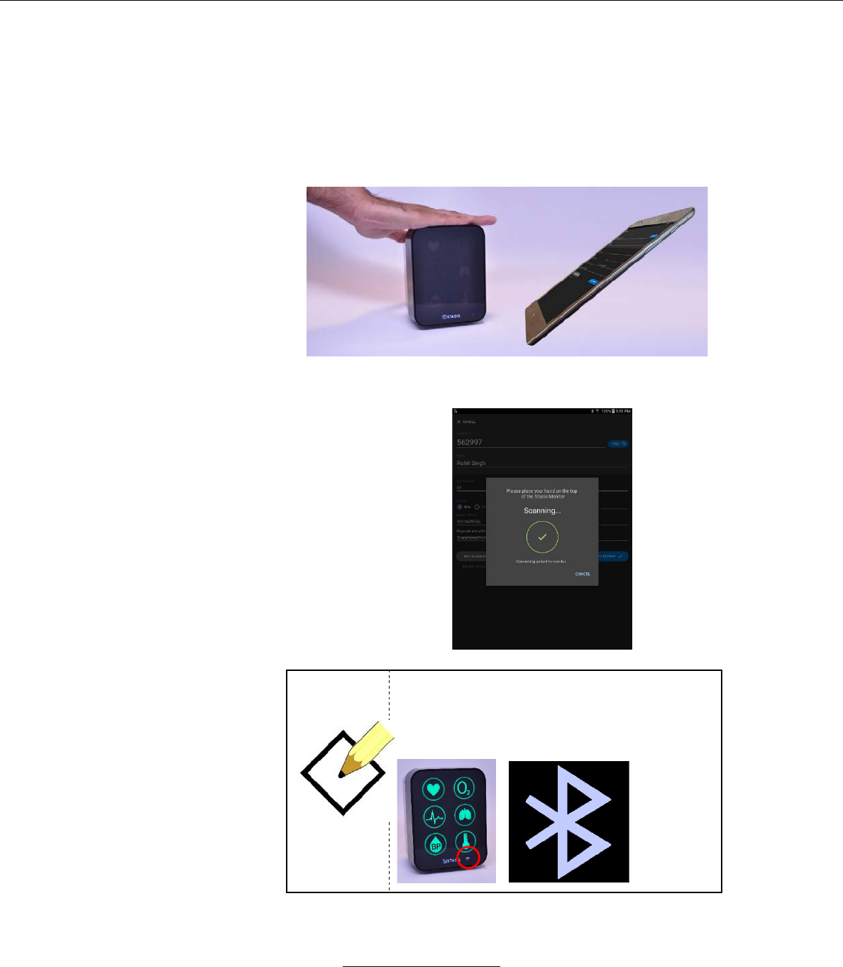
iii. When the patient information is entered, and the user
pressed the Admit Patient button, the user will be
prompted to sync with the SMS.
G. Syncing the Tablet to a specific SMS Monitor
1. Place your hand on the top of the SMS monitor while holding the tablet.
a. As the tablet and the monitor sync, the tablet screen displays
the following:
NOTE
For the Sync to occur successfully between
the SMS and the Tablet there must be a valid
Bluetooth connection. On the Monitor, this is
indicated by flashing the Bluetooth icon.
Stasis Monitoring System User’s Guide
Page 47
GPD-0001 Rev B
NOTE
For the Sync to occur successfully between
the SMS and the Tablet a patient must have
been selected or admitted on the Tablet.
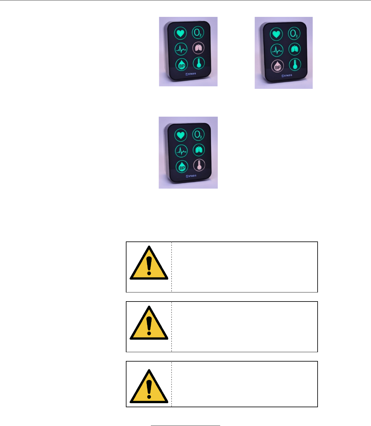
b.
If no sensors are
connected to the patient,
then the vital sign icons
will illuminate in white:
Attaching Sensors to and Operating the Monitor
WARNING
Ensure that all sensors/cuffs are connected to
the patient properly.
1. Pulse Rate / Oxygen Saturation Monitoring
Stasis Monitoring System User’s Guide
Page 48
GPD-0001 Rev B
a. Attaching the SpO2 Sensor to System
i. Insert the grey plug on the end of the SpO2 sensor
into the port marked SpO2 on the back of the SMS
(Note: Despite both having blue keying color, the
SpO2 connector can not plug into ECG connector
port due to unique connector keying).
ii. It is necessary to align the two protruding rails on
the plug in to the two slots on the port.
iii. When the SpO2 sensor is connected, the SMS
monitor will display the SpO2 icon in green.
b. Attaching Sensor to Patient
i. Clamp the prongs of the sensor, opening it.
ii. Place the sensor on the finger.
Stasis Monitoring System User’s Guide
Page 49
GPD-0001 Rev B
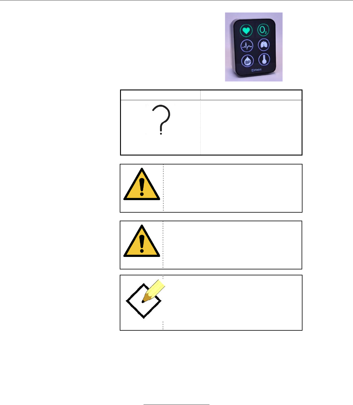
c.
When the SpO2 sensor is
connected and a reading
is being acquired, SpO2
and HR icons will flash
white. Once a reading is
acquired, the SMS will
display the SpO2 and HR
icons in green if no alarm
condition is active.
Symbol
Description
Signal Inadequacy
Indicator
This symbol indicates a
potentially incorrect SpO2 or
pulse rate value. It will appear
next to the SpO2 reading.
WARNING
Do not immerse or wet the SpO2 sensor.
WARNING
Bright light on the SMS SpO2 sensor may
result in inaccurate measurements.
NOTE
Place the SpO2 sensor on the finger in a
manner which results in the molded imprint of
the finger and nail is on the same side of the
finger as the nail.
Stasis Monitoring System User’s Guide
Page 50
GPD-0001 Rev B
2. ECG / Respiration Rate Monitoring
a. Attaching Sensor to System
i. Insert the grey plug on the end of the SpO2 sensor array
into the port marked ECG on the back of the SMS
(Note: Despite both having blue keying color, the
ECG connector can not plug into SpO2 connector
port due to unique connector keying).
ii. It is necessary to align the protruding rail on the
plug in to the slot on the port.
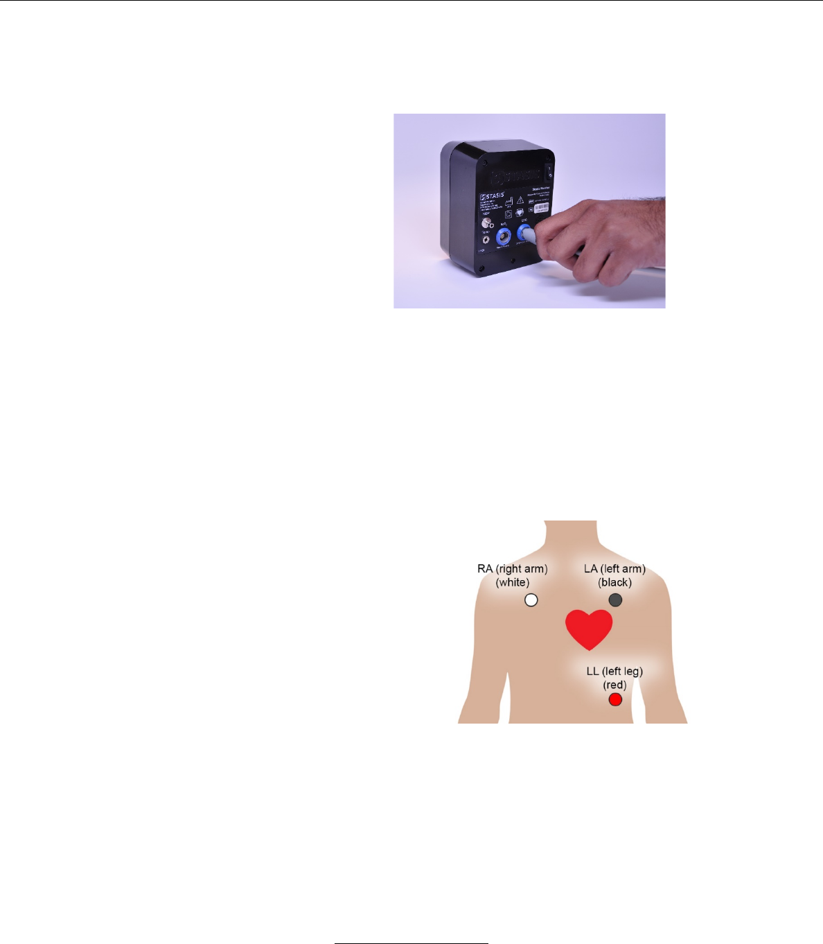
b. Attaching Sensor to Patient
i. Place ECG electrodes according to standard clinical
practice.
c. When the ECG sensor is connected and a reading is being
acquired, ECG, Resp and HR icons will flash white. Once a
reading is acquired, the SMS will display the ECG, Resp and
HR icons in green if no alarm condition is active.
Stasis Monitoring System User’s Guide
Page 51
GPD-0001 Rev B
WARNING
Inappropriate application or duration of SpO2
or ECG sensors may result in tissue damage.
Inspect the SpO2 and ECG sensor sights as
directed in the SpO2 and ECG sensor
directions for use.
WARNING
Only use the same type of ECG electrodes
for the various sites on the body. Mixing
ECG electrode types can adversely affect
ECG measurements.
3. Blood Pressure Monitoring
a. Attaching Sensor to System
i. Press the pneumatic connector on the end of the
cuff on to the nipple-connector on the back of the
SMS device.
ii. In order for the connection to lock, it is necessary
to pull back on the outer cannula of the pneumatic
connector while pressing it on to the nipple.
b. Placing the cuff on the patient.
Stasis Monitoring System User’s Guide
Page 52
GPD-0001 Rev B
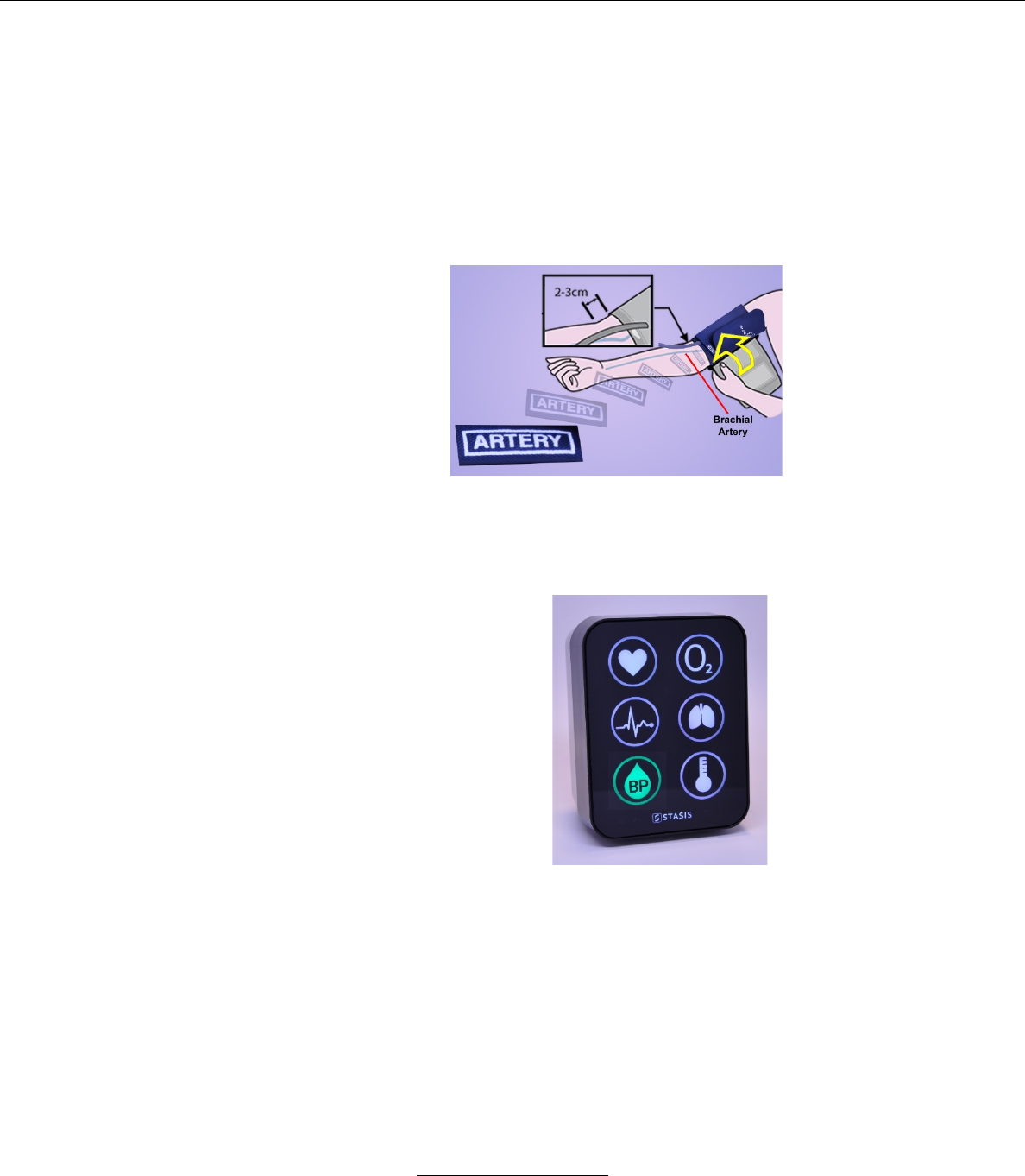
i. Most measurement errors occur by not taking the
time to choose the proper cuff size. Wrap the cuff
around patient arm and use the INDEX line to
determine if patient arm circumference falls within
the RANGE area. Otherwise, choose the
appropriate smaller or larger cuff.
ii. Palpate/locate the brachial artery and position the
BP cuff so that the ARTERY marker and the
pneumatic tube points to the brachial artery. Wrap
the BP cuff snugly around the arm.
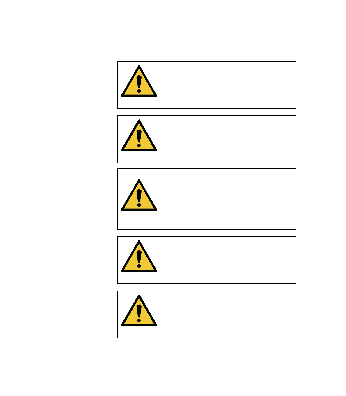
c. When the NIBP cuff is connected and a reading is being
acquired, the NIBP icon will flash white. Once a reading is
acquired, the SMS will display the NIBP icon in green if no
alarm condition is active.
d. When taking blood pressure measurements, ensure that:
i. The patient is comfortably seated
ii. The patient’s legs are uncrossed
iii. The patient’s feet are flat on the floor
iv. The patient’s back and arm are supported
v. The middle of the cuff is at the level of the right atrium
of the heart
Stasis Monitoring System User’s Guide
Page 53
GPD-0001 Rev B
vi. The patient is relaxed as possible and does not talk
during the measurement
vii. 5 minutes elapse with the patient in the correct position
before the first measurement is taken
WARNING
The accuracy of the blood pressure readings
can be impacted by extremes of temperature,
humidity, or altitude.
WARNING
Make certain that the NIBP cuff tube is not
bent, compressed, or restricted during
inflation and deflation, particularly after a
change in patient body position.
WARNING
Do not wrap the cuff on the following parts of
the patient.
• An upper arm on which an SpO2 sensor, IBP
catheter, or other monitor sensor is
connected.
• An upper arm on which an intravenous drip
or blood transfusion is being performed.
• An upper arm with a shunt for hemodialysis.
WARNING
The blood pressure reading may be affected
by the measurement site, the position of the
patient, patient exercise, or the patient’s
physiological condition.
WARNING
If the NIBP cuff, SpO2 sensor or temperature
sensor is used on a patient with an infection,
it is the responsibility of the healthcare
professionals to treat the cuff or sensors as
medical waste or consider if appropriate
sanitizing cuff or sensors before reuse.
Stasis Monitoring System User’s Guide
Page 54
GPD-0001 Rev B
WARNING
Do not use sensors/cuffs prior that appear to
be damaged as damaged sensors/duffs may
cause inaccurate performance or device
failure.
WARNING
Ensure that all sensors/cuffs are connected to
the SMS properly.
CAUTION
Only use a GE DURA-CUF NIBP cuff on this
device.
CAUTION
Use the appropriate size NIBP cuff to ensure
correct measurements. If the NIBP cuff is too
large the measured blood pressure value tends to
be lower than the actual blood pressure. If the
NIBP cuff is too small the measured blood
pressure value tends to be higher than the actual
blood pressure.
CAUTION
NIBP measurements should be performed
with the cuff placed on the upper arm.
CAUTION
Make certain that the part of the cuff is
approximately the same elevation as the
heart (A difference of 10cm (4in) in height
may cause a variation in the measured blood
pressure value of up to 7-8mmHg.
CAUTION
If the NIBP cuff is wrapped over thick clothing
it could affect the accuracy of the measured
blood pressure.
Stasis Monitoring System User’s Guide
Page 55
GPD-0001 Rev B
CAUTION
If patient sleeve is rolled up in a manner
where it exerts pressure on the arm it could
affect the accuracy of the measured blood
pressure.
CAUTION
If the patient moves or talks during the blood
pressure measurement it could affect the
accuracy of the measured blood pressure.
CAUTION
Make certain that the pneumatic connector is
locked on the pneumatic nipple on the SMS
unit. If the pneumatic connection is not
secure it could affect the accuracy of the
readings.
CAUTION
Make certain that the cuffing tubing does not
have a heavy object resting on it and that it
has no kinks, as restrictions in air flow to the
cuff can affect the accuracy of the NIBP
readings.
CAUTION
Do not use the NIBP cuff if it is damaged or
has holes.
4. Temperature Monitoring
a. Attaching Temperature Sensor to System
Stasis Monitoring System User’s Guide
Page 56
GPD-0001 Rev B
i. Insert the male connector on the Temperature Sensor
in to the Temperature port on the SMS monitor.
b. When the temperature sensor is connected and a reading is
being acquired, the temperature icon will flash white. Once a
reading is acquired, the SMS will display the temperature
icon in green if no alarm condition is active.
5. Alarms
WARNING
When the SMS monitor alarms or alerts, it is
the responsibility of healthcare professionals
to review patient condition clinically before
conducting interventional measures.
a. When an alarm condition is active, the relevant icons will
change color and/or flash based on the priority of the alarm.
Alarm conditions are detailed in Section IX.
ALARM: HR limits exceeded
ALARM: SpO2 limits exceeded
Stasis Monitoring System User’s Guide
Page 57
GPD-0001 Rev B
ALARM: Respiration rate limits
exceeded
ALARM: Systolic NIBP or
Diastolic NIBP limits exceeded
ALARM: Temperature limits
exceeded
b. When an alarm condition is active, an audible alarm may
sound on the SMS system. Alarm conditions and audible
alarms are detailed in Section IX.
WARNING
Ensure that the speaker is clear of any
obstructions. Failure to do so could result in
an inaudible alarm tone.
WARNING
If the Alarms are paused or turned off there is
no notification if a clinically significant change
in patient vital signs occurs. Observe the
patient by other means when alarms are
paused or turned off.
Should the SMS monitor lose Bluetooth
connection to the SMS tablet the Alarm
function will not function. The tablet must not
be relied upon to annunciate alarms.
Stasis Monitoring System User’s Guide
Page 58
GPD-0001 Rev B
WARNING
c. Alarm audio may be paused by the Tablet. If an alarm’s audio
is currently paused, the Alarm Audio Paused Icon will be
displayed in white. Alarm pause functionality is detailed in
Section IX.
WARNING
If alarms are paused or disabled check the
patient frequently to make certain that his/her
condition is acceptable.
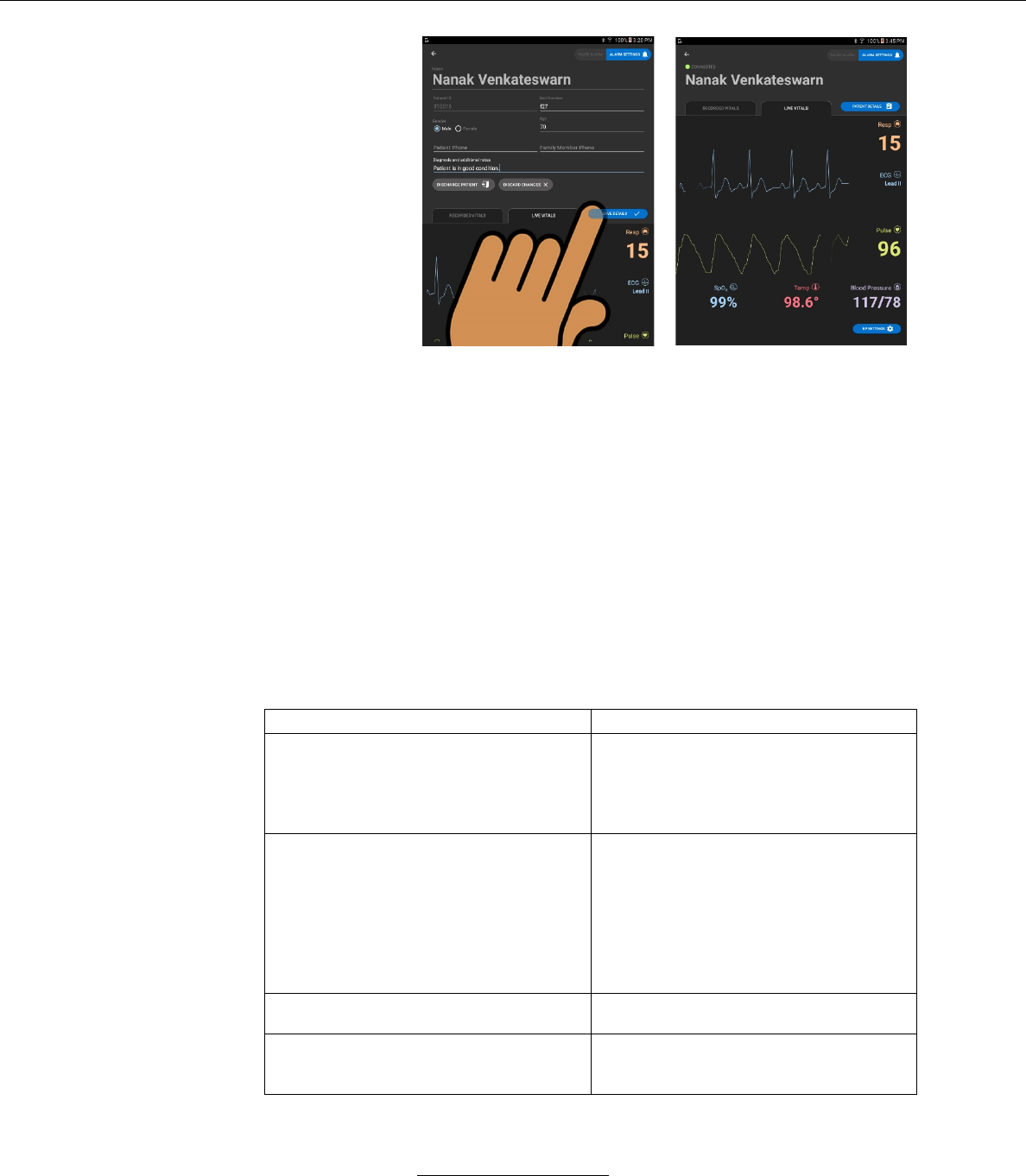
H. Operating the Tablet
When the Patient Information is input or the Patient is selected from the
patient list the LIVE VITALS screen will display
WARNING
If the user is uncertain about the accuracy of
any measurement, check patient vital signs
by an alternative means and make certain
that the sensors and/or SMS is functioning
properly.
WARNING
The Bluetooth range of the tablet and monitor
connection is 20 feet. Attempting to use the
tablet outside of this range may result in
unreliable operation.
Stasis Monitoring System User’s Guide
Page 59
GPD-0001 Rev B
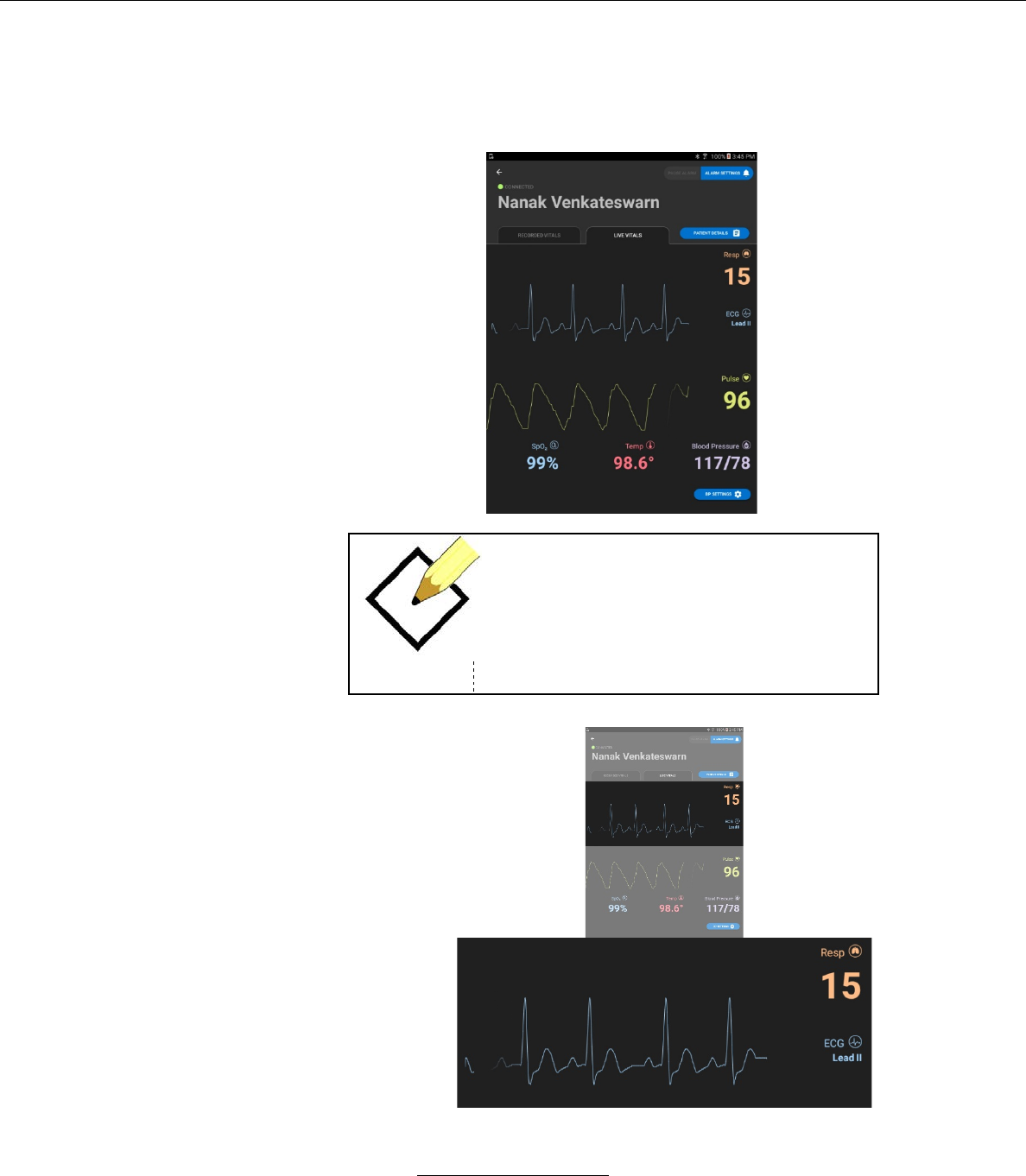
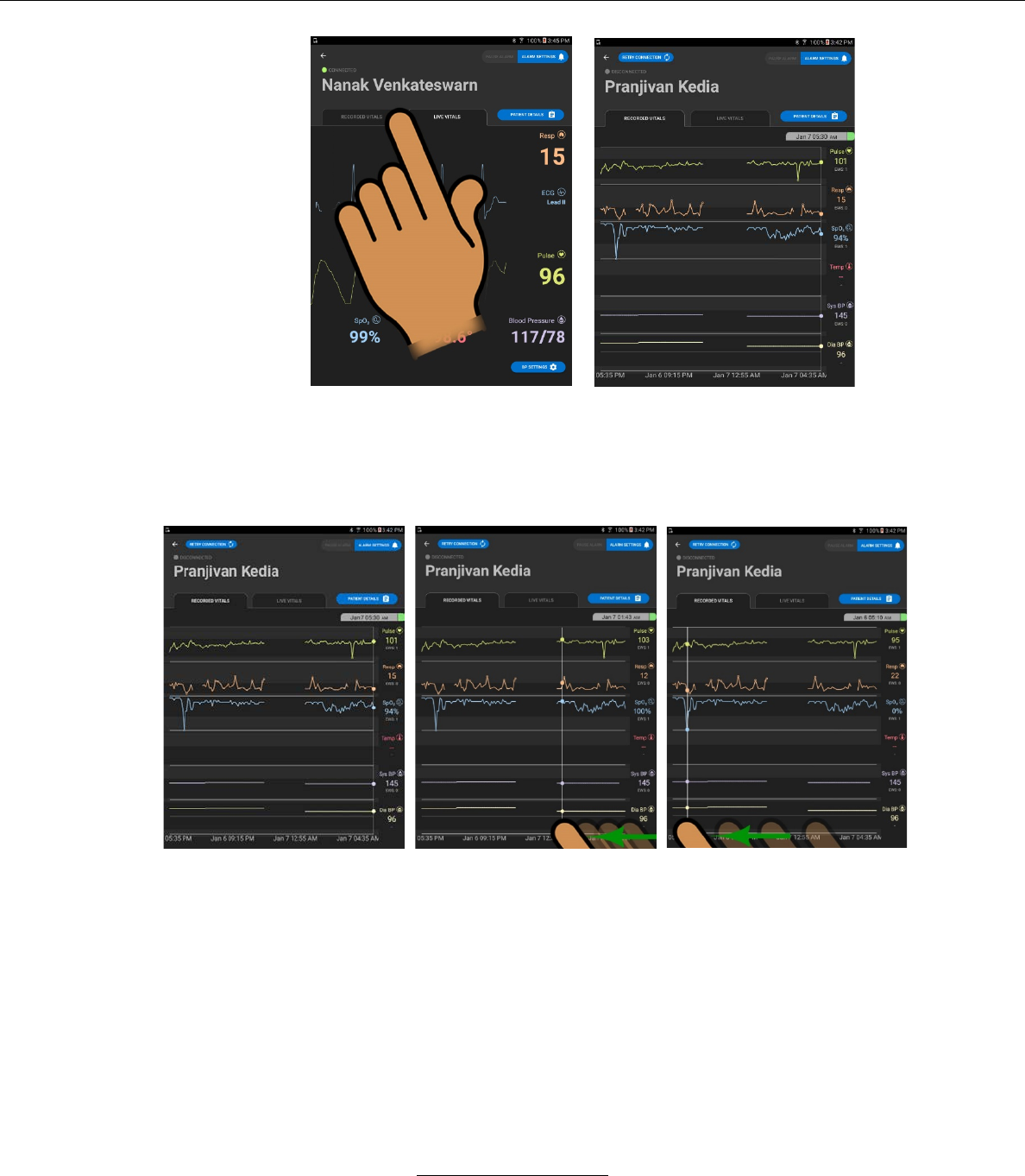
1. The LIVE VITALS screen.
If the user wishes to view the live vital sign readings, he/she may proceed.
NOTE
If the SMS which the patient is connected to
is not in Bluetooth range, the screen will
prompt the user to RETRY CONNECTION.
a. ECG Display
Stasis Monitoring System User’s Guide
Page 60
GPD-0001 Rev B
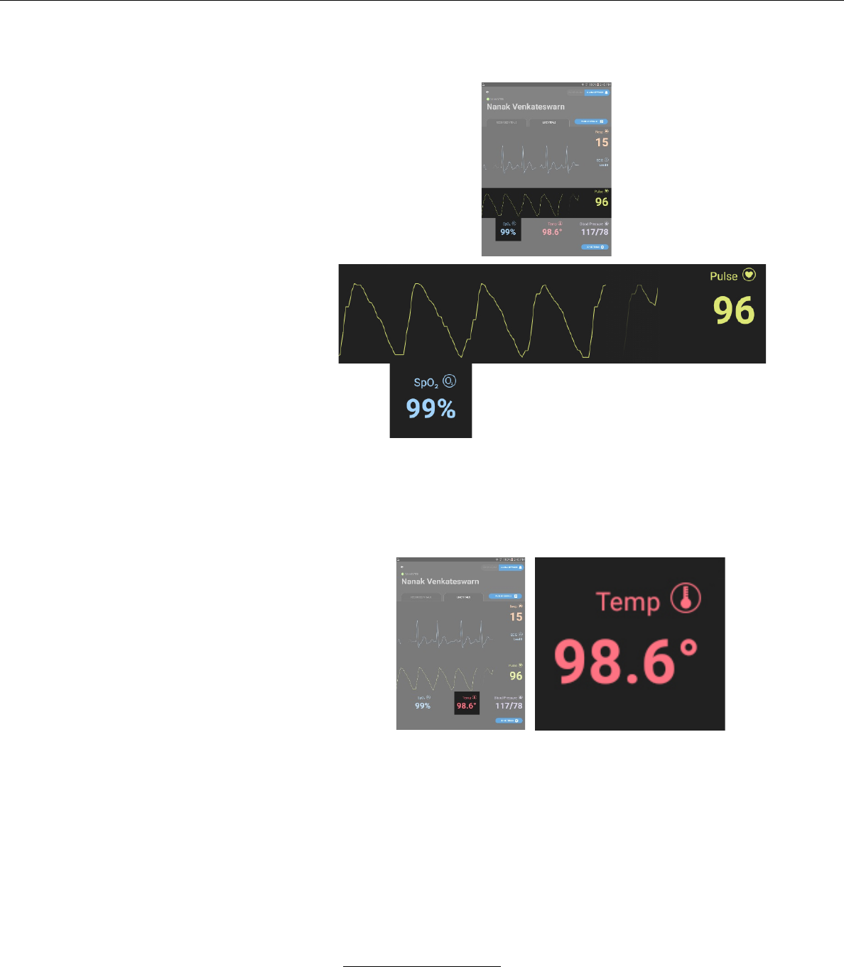
b. SpO2 Display
i. The oxygen Saturation level (SpO2) is displayed
numerically below the plethysmograph.
ii. The pulse rate is derived from the SpO2 sensor. It
is displayed to the right of the plethysmograph.
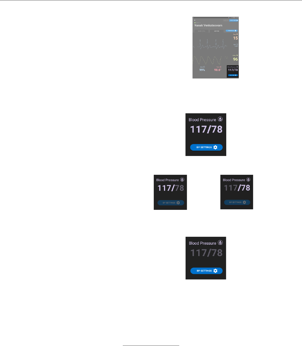
c. Temperature Display
i. Patient temperature is displayed below the
plethysmograph.
Stasis Monitoring System User’s Guide
Page 61
GPD-0001 Rev B
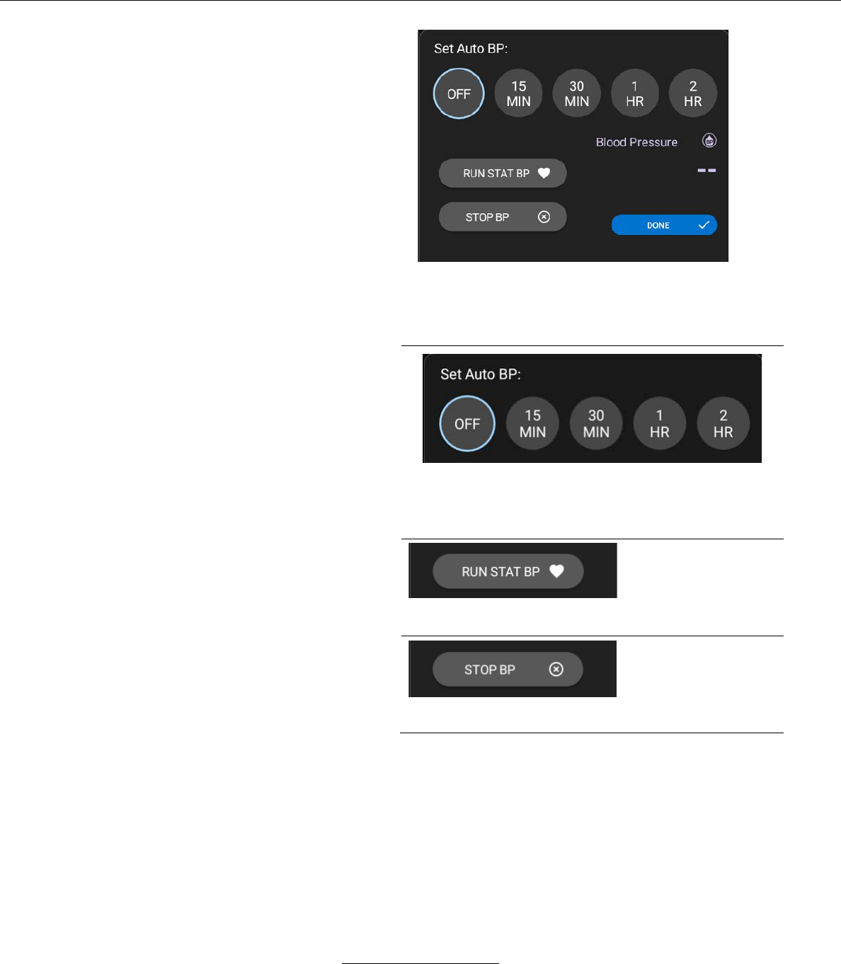
d.
Blood Pressure Display.
i. The non-invasive blood pressure (NIBP) reading is
displayed in the lower right-hand corner of the LIVE
VITALS screen.
– The display updates the systolic and diastolic
readings obtained from the cuff with each reading.
Systolic NIBP reading
Diastolic NIBP reading
– The user may select several functions for NIBP
readings by pressing the BP SETTINGS button.
When selected, the BP SETTINGS button
displays the following window.
Stasis Monitoring System User’s Guide
Page 62
GPD-0001 Rev B
From the Blood Pressure Settings window, the
user may perform the following functions:
The System automatically obtains NIBP readings at selected
intervals. The user may select the interval by pressing one of the
above intervals.
Pressing the STAT BP
button immediately
inflates the blood
pressure cuff and
initiates and NIBP
reading.
Pressing the STOP BP
button immediately
deflates the blood
pressure cuff and
cancels the NIBP
reading.
2. RECORDED VITALS screen
If the user wishes to view the RECORDED VITALS values, he/she may
press the RECORDED VITALS tab on the LIVE VITALS SCREEN
Stasis Monitoring System User’s Guide
Page 63
GPD-0001 Rev B
è
a. The RECORDED VITALS screen will display a historical graph
of various vital signs, plus the numeric values of each recorded
vital sign at the selected time.
i. The user may select a record by pressing on the graph,
revealing the vital sign readings for the selected time.
ii. The user may return to the LIVE VITALS screen by
selecting the LIVE VITALS tab from the RECORDED
VITALS screen.
Stasis Monitoring System User’s Guide
Page 64
GPD-0001 Rev B
è
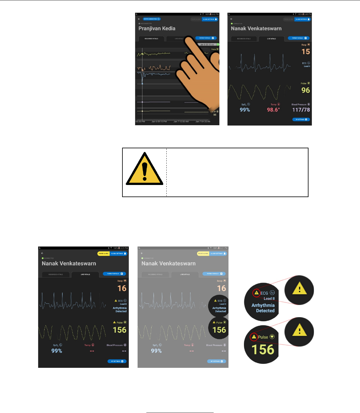
3. Alarms
WARNING
When the SMS monitor alarms or alerts, it is
the responsibility of healthcare professionals
to review patient condition clinically before
conducting interventional measures.
a. Alarm Displays on Live Vitals screen
i. If a medium or low priority physiological alarm is
active, a yellow CAUTION icon will illuminate next
to the specific vital sign that is outside of the
ALARM SETTINGS.
ii. If a high priority physiological alarm is active, a red
CAUTION icon will illuminate next to the specific vital
sign that is outside of the ALARM SETTINGS.
Stasis Monitoring System User’s Guide
Page 65
GPD-0001 Rev B
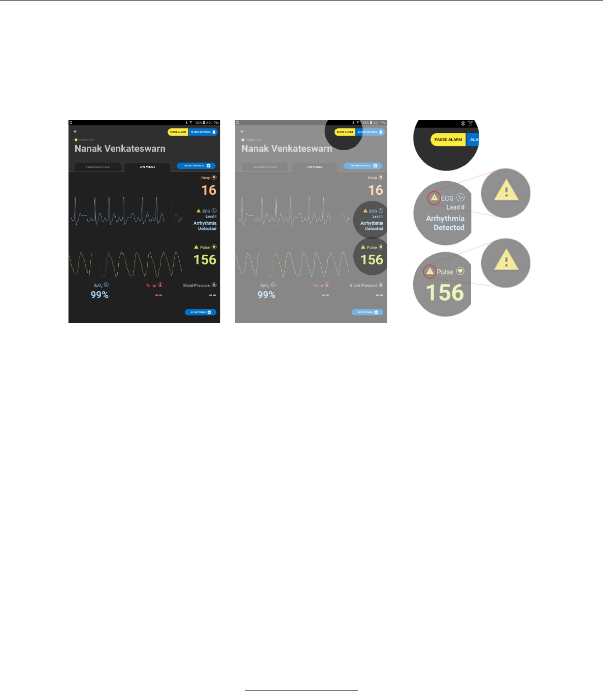
iii. If a low priority technical alarm is active, a blue
CAUTION icon will illuminate next to the specific vital
sign that is outside of the ALARM SETTINGS.
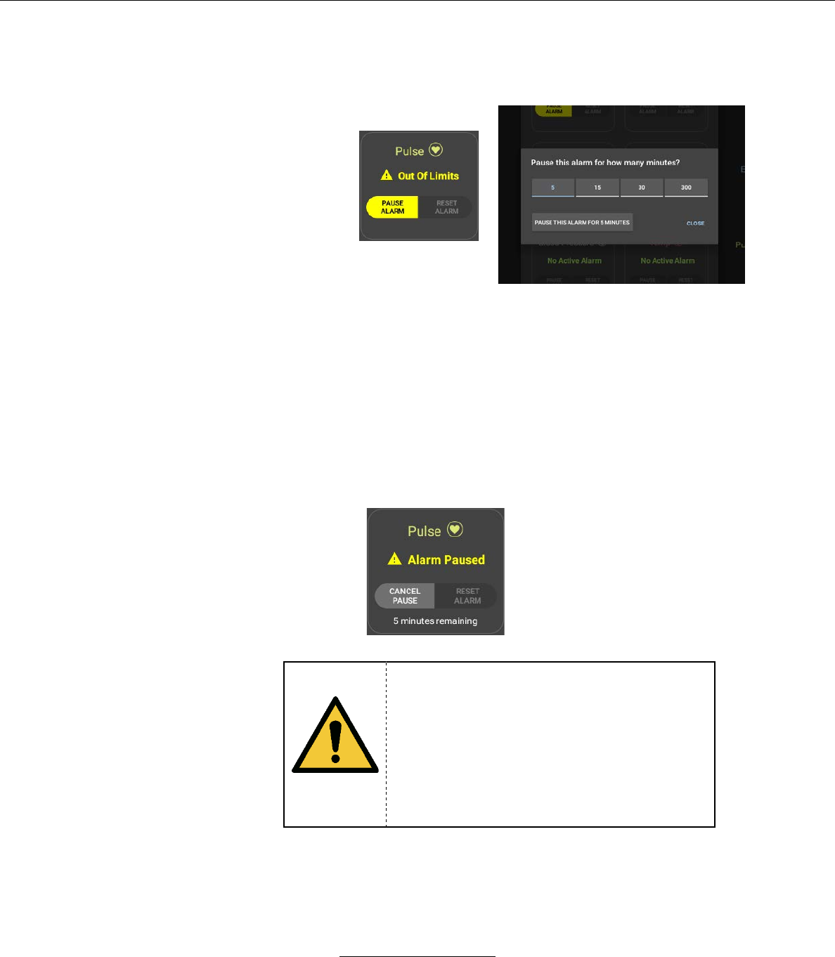
iv. Active alarms may be viewed and paused by pressing
the PAUSE / RESET ALARMS button at the upper right-
hand side of the LIVE VITALS SCREEN.
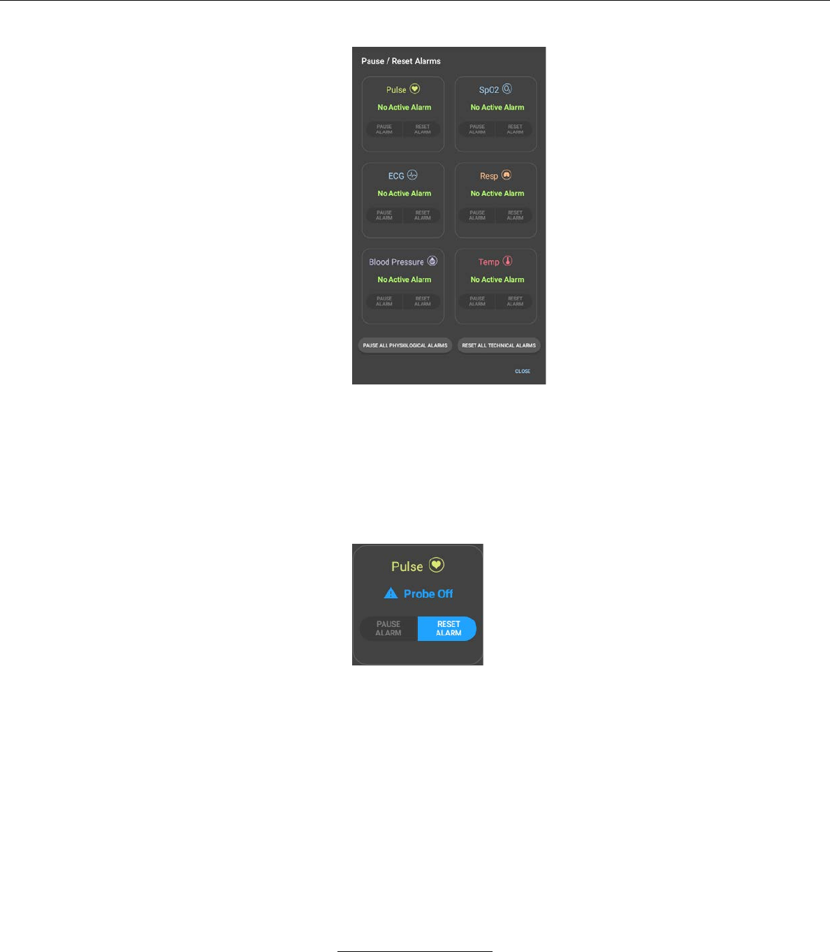
v. The PAUSE / RESET ALARMS screen shows a detailed
view of each active alarm. If a vital sign has no active
alarm, the screen will display “No Active Alarm”.
– Active low priority technical alarms are shown with a
solid blue CAUTION icon.
– Active low priority physiological alarms are shown with
a solid yellow CAUTION icon.
– Active medium priority physiological alarms are shown
with a flashing yellow CAUTION icon.
– Active high priority physiological alarms are shown
with a flashing red CAUTION icon.
Stasis Monitoring System User’s Guide
Page 66
GPD-0001 Rev B
vi. From the PAUSE / RESET ALARMS screen, the user
can reset any active Probe Off alarm by pressing the
RESET ALARM button next to the relevant vital sign.
The user can also reset all active Probe Off alarms by
pressing the RESET ALL TECHNICAL ALARMS button.
vii. From the PAUSE / RESET ALARMS screen, the user
can pause any active physiological alarm by pressing the
PAUSE ALARM button next to the relevant vital sign.
The user can also pause all active physiological alarms
by pressing the PAUSE ALL PHYSIOLOGICAL
ALARMS button.
– If any PAUSE ALARM button is pressed, a
second window appears, prompting the user to
specify the alarm pause time.
Stasis Monitoring System User’s Guide
Page 67
GPD-0001 Rev B
These pause time options are configured by the
user from the HOSPITAL ADMINISTRATOR
SETTINGS screen.
viii. From the PAUSE / RESET ALARMS screen, the user
can re-enable a paused physiological alarm by pressing
the CANCEL PAUSE button next to the relevant vital
sign.
– Text indicating the amount of time the alarm will
continue to be paused for will appear under the
CANCEL PAUSE and RESET ALARM buttons
for the relevant vital sign
WARNING
When an alarm notification occurs it is an indicator
that the patient needs increased attention.
Therefore, it is important for clinical personnel
to pay particular attention to the patient. It is
the responsibility of the healthcare
professional to take appropriate clinical
actions, including physically check on the
patient if necessary, before enabling the
PAUSE ALARM function.
Stasis Monitoring System User’s Guide
Page 68
GPD-0001 Rev B
NOTE
The PAUSE ALARM button will only
illuminate when an alarm condition exists.
NOTE
Any displayed ECG alarms are based on a
rate-based detection algorithms, not a
waveform-based analysis
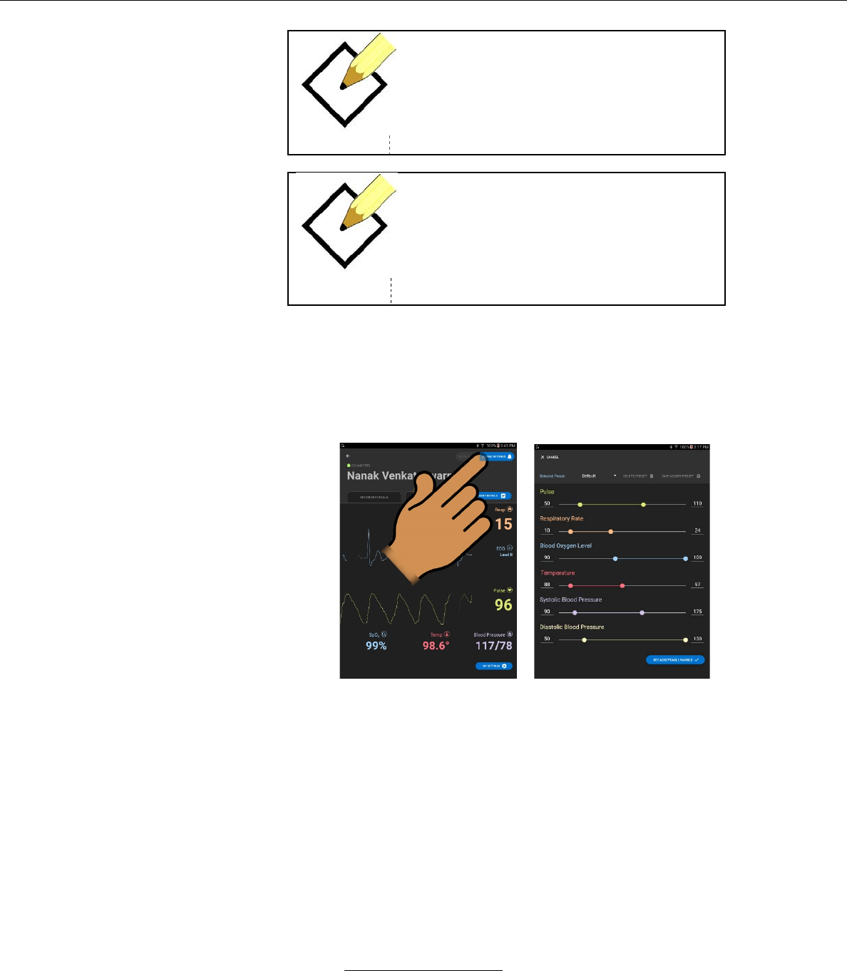
Accepting / Adjusting Alarm Values
i. Alarm values may be viewed or adjusted by pressing
the ALARM SETTINGS button on the upper right hand
portion of the LIVE VITALS screen.
è
ii. The minimum alarm
values will be dis-
played numerically
on the left.
iii. The maximum
alarm values will be
displayed numer-
ically on the right.
iv. The alarm adjust-
ments sliders are
displayed in the
middle.
Stasis Monitoring System User’s Guide
Page 69
GPD-0001 Rev B
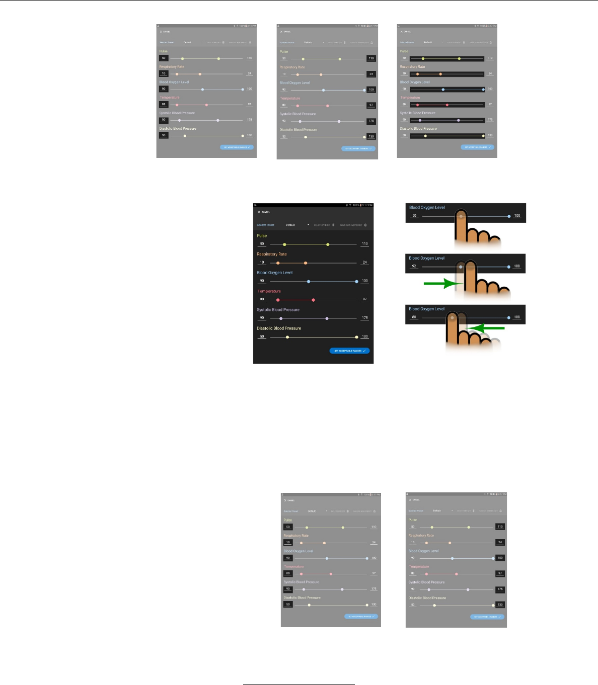
v. The minimum and maximum alarm values may be ad-
justed by the sliding bars on the ALARM SETTING screen
– Pressing a finger on the left-hand circle on the alarm line
and moving that ball to the right raises the alarm value.
– Pressing a finger on the right-hand circle on the alarm line
and moving that ball to the left lowers the alarm value.
vi. The minimum and maximum alarm values may also
be adjusted by selecting the current alarm values,
and entering a new value.
Stasis Monitoring System User’s Guide
Page 70
GPD-0001 Rev B
vii. Default Alarm Values
Default alarm values can be viewed in the Alarms
section of this document.
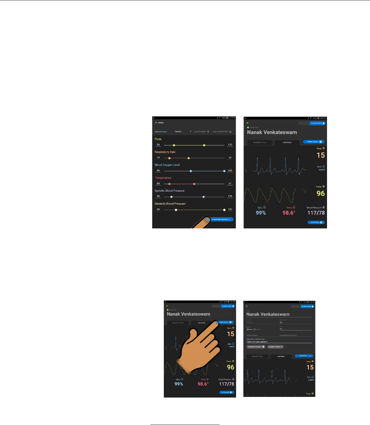
viii. If the Alarm Values are acceptable then the user may
return to the Live Vitals screen by pressing the SET
ACCEPTABLE RANGES button on the lower left-hand
corner of the ALARM VALUES screen.
After pressing SET ACCEPTABLE RANGES the
Tablet will return to the LIVE VITALS screen.
è
– pressing a finger on the left-hand circle on the alarm
line and moving that ball to the right.
4. Patient Details
a. The PATIENT DETAILS screen may be accessed by
pressing the PATIENT DETAILS button on the right-hand
side of the LIVE VITAL SIGNS or RECORDED VITALS
screens.
è
Stasis Monitoring System User’s Guide
Page 71
GPD-0001 Rev B
b. PATIENT DETAILS screen
i. In this screen the user may edit the following
– Patient Name
– Patient ID number
– Patient Bed Number
– Patient Age
ii. The user may also add notes by pressing the
NOTES field and typing in notes with the screen-
provided alpha-numeric keyboard.
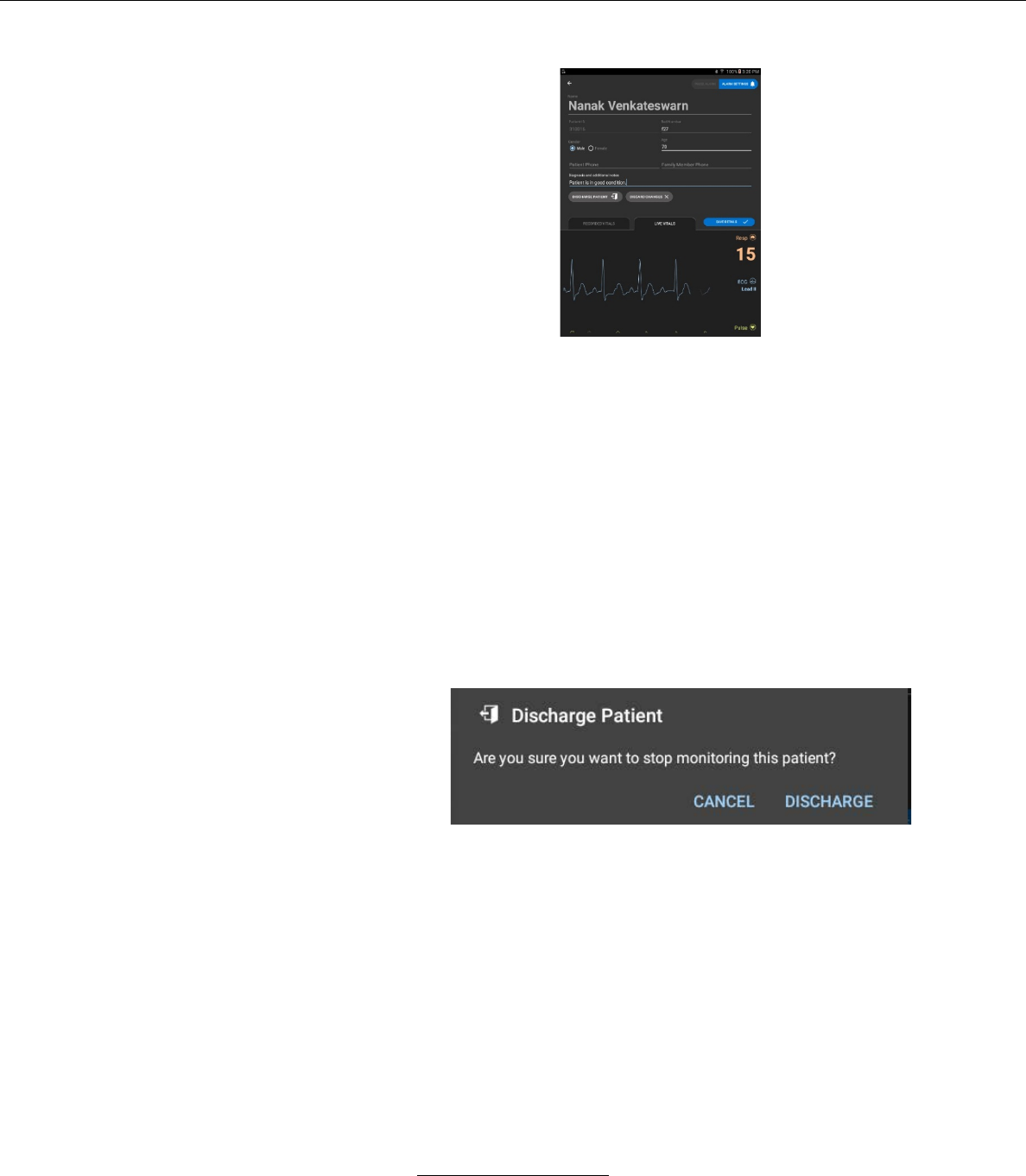
iii. The user may also discharge the patient.
iv. In this screen the user may also discharge the patient
by pressing the DISCHARGE PATIENT button.
If the user chooses DISCHARGE PATIENT, a
window will pop-up asking the user to confirm the
order to discharge the patient.
v. In this screen the user may cancel all edits by
pressing the DISCARD CHANGES button.
vi. In this screen the user may save patient detail edits
by pressing the SAVE DETAILS button.
Stasis Monitoring System User’s Guide
Page 72
GPD-0001 Rev B
è
– When the SAVE DETAILS button is pressed the
screen returns to the LIVE VITALS or
RECORDED VITALS screen.
5. Safely Terminating Use
a. To safely terminate use of the SMS, disconnect the sensors
from the patient and turn off the monitor using the power
switch on the rear of the device.
6. Error, System, and Fault Messages
Message
Potential Causes
The Stasis Tablet Application has
encountered a problem that it cannot
recover from. Please try restarting the
tablet. If this problem persists, contact
Stasis.
Nonvolatile memory (local storage) is
corrupted.
Program memory is corrupted.
Tablet BLE module (Android
framework) is unresponsive.
Add Patient: Could not add patient. The
clinician you entered does not exist.
Please select a clinician from the
dropdown.
Patient Details: Could not save
changes. The clinician you entered
does not exist. Please select a clinician
from the dropdown.
Invalid clinician name entered in the
'Clinician name' field when admitting a
patient.
Could not connect to Monitor. Patient
was not created.
Monitor BLE connection/write operation
failure when admitting a patient.
Patient ID found on patient list.
User enters ID of patient already
admitted (i.e. active) when attempting to
add a new patient.

Stasis Monitoring System User’s Guide
Page 73
GPD-0001 Rev B
Patient could not be admitted because
the monitor you're trying to admit to is
not compatible with this version of the
tablet application. The monitor version
is %s and the tablet version is X.
Tablet application and Monitor P1
application on incompatible major/minor
software versions.
<Field Name> is a required field.
A field marked as required (in hospital
authority settings) is left empty when
adding a new patient.
Error accessing patient file. Please try
again.
Patient file fails to successfully load
from local storage.
Unable not connect to Monitor, please
try again.
Unable to establish connection with
Monitor when patient file is opened for
admitted patient.
Alarm could not be silenced because
tablet is disconnected from the monitor.
Connection with Monitor lost when
attempting to pause alarms.
Check BP Cuff Placement.
Unrealistic BP values (out of BP
board/monitor error checking ranges)
detected.
NIBP Failure detected.
Monitor detects error with BP board.
Sorry, no Monitor connection was
detected. Your changes will not be
saved.
Writing new alarm settings to Monitor
after returning from alarm settings view
fails.
You cannot name your preset 'Default'
or 'Custom', sorry.
User tries to name a new custom preset
'Custom' or 'Default'.
Out of bounds. Enter a value between
<min_value> and <max_value>.
User tries to enter an invalid value for
alarm settings ranges.
Stasis Monitoring System User’s Guide
Page 74
GPD-0001 Rev B
X. ALARMS
WARNING
Do not set the alarm limits to extreme values to
prevent the triggering of alarms. This could lead to
injury or death to a patient if an alarm does not
sound for a dangerous condition.
WARNING
It is the responsibility of the operator to ensure that
the alarm pre-set is suitable for each patient.
The functionality of the alarm system is checked every time the Stasis Monitor is turned on. The
alarm speaker should beep 3 times every time the Stasis Monitor is turned on using the power switch on
the rear of the device. If no audio is heard when the Stasis Monitor is turned on, or the audio sounds
muffled or otherwise abnormal, remove the monitor from service immediately and notify Stasis to have the
monitor serviced.
After the loss of the external power source the monitor will retain its alarm settings for a minimum
of 3 hours.
The volume of the audio alarms is as follows (A-weighted):
Low Priority Alarms: 62.5 dB(A)
Medium Priority Alarms: 62.2 dB(A)
High Priority Alarms: 60.5 dB(A)

Stasis Monitoring System User’s Guide
Page 75
GPD-0001 Rev B
Alarm Types:
Type
Priority
Visual Indication
Audible Indication
Asystole
(physiological)
High
Red icon, flashing at 2 Hz
(250 ms on, 250 ms off)
• 325 Hz, 100ms Beep
• Wait 100ms
• 325 Hz, 100ms Beep
• Wait 100ms
• 325 Hz, 100ms Beep
• Wait 300ms
• 325 Hz, 100ms Beep
• Wait 100ms
• 325 Hz, 100ms Beep
• Wait 10 seconds
• 325 Hz, 100ms Beep
• Wait 100ms
• 325 Hz, 100ms Beep
• Wait 100ms
• 325 Hz, 100ms Beep
• Wait 300ms
• 325 Hz, 100ms Beep
• Wait 100ms
• 325 Hz, 100ms Beep
• Wait 10 seconds
• Repea!
Heart rate, SpO2,
respiration rate,
NIBP, or
temperature alarm
limits exceeded
(physiological)
Medium
Yellow icon, flashing at 0.625 Hz
(800 ms on, 800 ms off)
• 325 Hz, 200ms Beep
• Wait 200ms
• 325 Hz, 200ms Beep
• Wait 200ms
• 325 Hz, 200ms Beep
• Wait 20 seconds
• Repeat!
Critical Battery
(technical)
High
Red battery icon, flashing at 2 Hz
(250 ms on, 250 ms off)
Same as high priority
physiological
Low Battery
(technical)
Low
Yellow battery icon, constantly on
None
Other Technical
Alarms
Low
Cyan icon, constantly on
• 325 Hz, 200ms Beep
• Wait 200ms
• 325 Hz, 200ms Beep
• Wait 20 seconds
• Repeat

Stasis Monitoring System User’s Guide
Page 76
GPD-0001 Rev B
Types of Technical Alarms:
• NIBP failure detected
• Pulse oximeter off patient
• ECG leads off patient
• Temperature probe off patient
• Pulse oximetry module hardware failure detected
• ECG module hardware failure detected
• NIBP module hardware failure detected
If multiple alarms are active simultaneously, the system will sound the highest-priority
active alarm, and display all active alarms.
If the Stasis System detects a module failure, the icon for the associated vital signs will
illuminate in cyan and the Stasis logo will illuminate red. In case this occurs, contact
Stasis customer support.
Alarm Deactivation:
Default alarm audio pause time: 60 seconds
Audio for all active physiological alarms can be paused for a specified duration
with the Stasis Tablet. The physiological alarms to have their audio paused can be
specified, or audio of all of the physiological alarms can be paused at once. This audio
paused state can be canceled by the Stasis Tablet, and the audio pause state will be
canceled automatically if the associated vital sign returns inside the set alarm limits.
The visual indication of the alarm state will not be affected by the alarm audio
pause.
Technical alarms can be reset by the Stasis Tablet. The technical alarms to be
reset can be specified, or all of the technical alarms can be reset at once. This reset
cannot be reversed.

Stasis Monitoring System User’s Guide
Page 77
GPD-0001 Rev B
Default Alarm Limits:
Default
Lower
Default
Higher
Minimum
Allowed
Maximum
Allowed
Pulse
50
110
30
150
Respiration
Rate
10
25
6
50
Blood
Oxygen
Level
90
100
82
100
Temperature
89
99
88
108
NIBP
Systolic
Blood
Pressure
90
180
70
230
Diastolic
Blood
Pressure
50
130
30
130
Alarm System Delays:
The following alarms will be activated within the following times after an alarm condition
is reached:
High priority alarm signal generation delay: 10 seconds
Medium priority alarm signal generation delay: 10 seconds
Low priority technical alarm signal generation delay: 10 seconds
Alarm System Security:
Hospital administrators are the only users who are authorized to make changes
to the alarm presets and alarm delay times. In order to enforce this, an administrator
PIN is required to be entered before changes to the restricted alarm settings can be
saved.
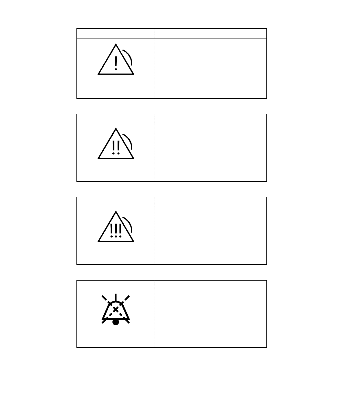
Stasis Monitoring System User’s Guide
Page 78
GPD-0001 Rev B
Description of Alarm Symbols:
Symbol
Description
Low-Priority
Alarm
This symbol indicates a low-
priority technical alarm. The
symbol appears on the tablet in
blue.
Symbol
Description
Medium-Priority
Alarm
This symbol indicates a medium-
priority physiological alarm. The
symbol appears on the tablet in
yellow.
Symbol
Description
High-Priority
Alarm
This symbol indicates a high-
priority physiological alarm. The
symbol appears on the tablet in
red.
Symbol
Description
Alarm Audio
Pause
This symbol indicates that alarm
audio is paused. Note that this
indicates that an alarm condition
is currently active, but the
associated alarm audio is
currently muted.
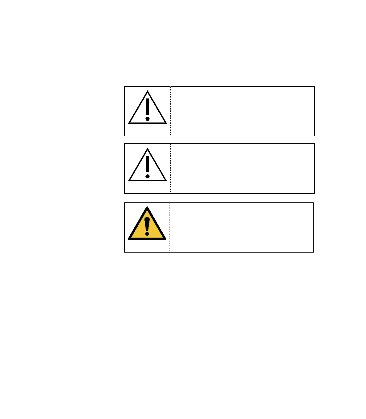
Stasis Monitoring System User’s Guide
Page 79
GPD-0001 Rev B
XI. SYSTEM MAINTENANCE
A. The system complies with IEC 60601-1/EN 60601-1 standards.
B. If the Stasis Monitor is in storage, check the battery every 3 months to
ensure that it is still able to charge and power the monitor.
C. Repair
CAUTION
If you believe that your SMS is in need of
repair, contact your Stasis sales
representative for instructions on sending the
system to Stasis for diagnosis and repairs.
CAUTION
Installation of unauthorized software will
result in the voiding of the SMS service
agreement.
WARNING
The battery can only be replaced by service
personnel using a tool.
D. NIBP Calibration Verification Procedure
This mode is restricted to access by the responsible organization and
service personnel and is not available in normal use.
a. Enable the “Show BP calibration button” feature in hospital administrator
settings.
b. Go to BP menu and start the Calibration.
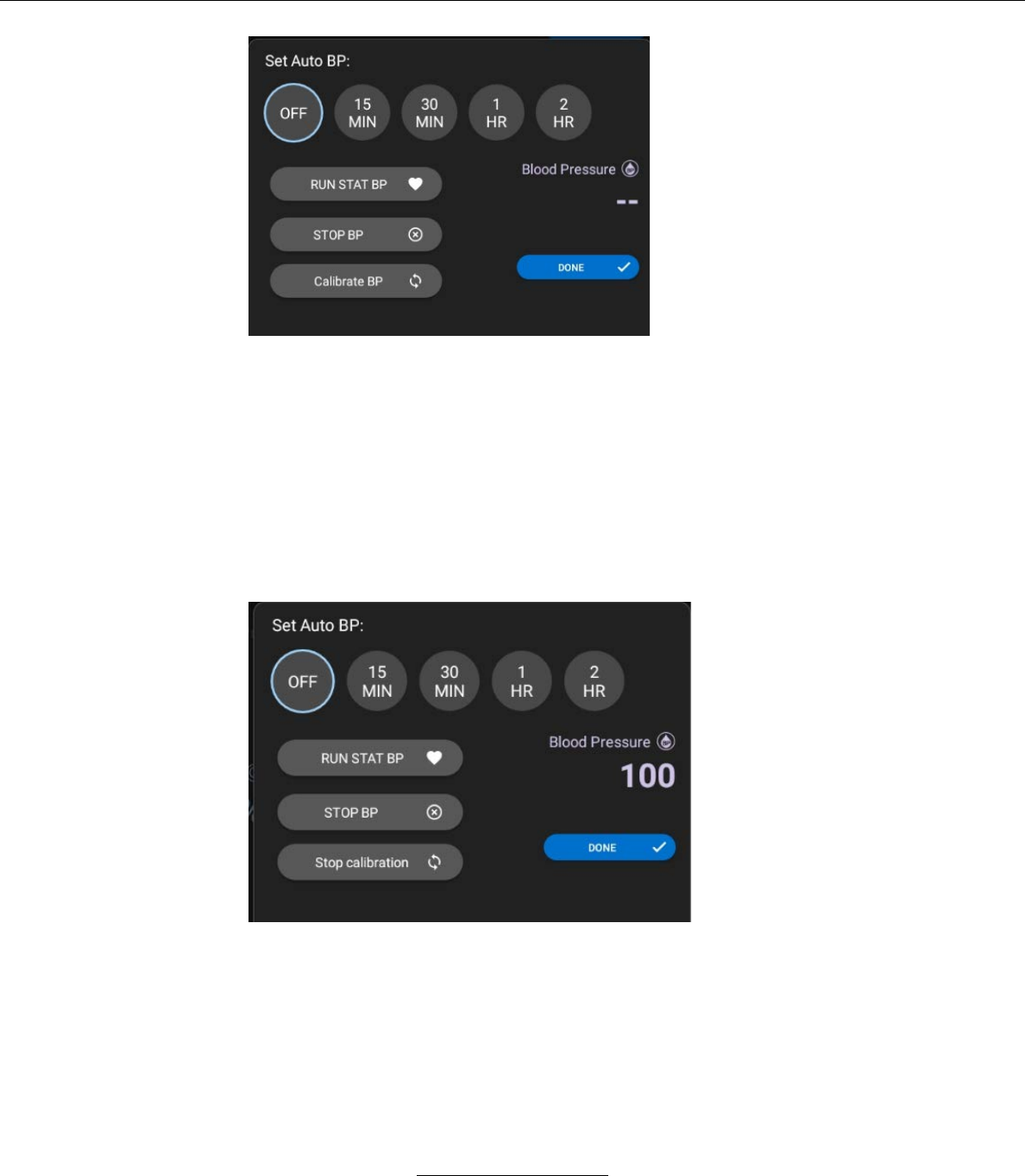
Stasis Monitoring System User’s Guide
Page 80
GPD-0001 Rev B
c. Set the Cuff pressure to 80, 100, 150,200,250 using a simulator or a
manual sphygmomanometer and note down the readings.
d. Stop the calibration after taking the readings.
e. The measured values should be less than or equal to +/- 3mmHg of the
actual Cuff pressure
f. If measured values are outside of the set cuff pressures, contact Stasis
for monitor refurbishment
Stasis Monitoring System User’s Guide
Page 81
GPD-0001 Rev B
E. Cleaning Instructions
1. Stasis Monitor
a. Turn off the SMS before cleaning.
b. Wipe exposed surfaces with a soft cloth or a pad
moistened with a mild detergent solution.
CAUTION
The SMS can be sanitized by wiping down
with a soap and water solution, 70% isopropyl
alcohol, or dilute glutaraldehyde solution.
CAUTION
Do not sterilize by autoclave or gas
sterilization methods.
WARNING
Do not spray, pour, or spill liquids into or onto
the unit, accessories, connectors, buttons, or
openings in the housing.
2. Reusable SpO2 Sensor
a. Disconnect the SpO2 sensor from the SMS before
cleaning
b. Clean the inside of the sensor, and the two optical
elements, with a cotton swab or equivalent.
c. Moisten cotton swab, or equivalent, with a mild
detergent solution or medical alcohol (70% isopropyl
alcohol solution).
Stasis Monitoring System User’s Guide
Page 82
GPD-0001 Rev B
WARNING
Do not immerse or wet the SpO2 sensor.
F. Disposal Instructions
WARNING
Dispose of all electrical components
associated with the SMS in accordance with
local requirements and regulations.

Stasis Monitoring System User’s Guide
Page 83
GPD-0001 Rev B
XII. OPERATING CONDITIONS
A. The system complies with IEC60601-1/EN 60601-1 standards.
B. Environmental Specifications:
1. Operating
Temperature
10oC - 40oC (50oF - 104oF)
Altitude
-390 m - 3,000 m
(-557 ft – 9,843 ft)
Pressure
71 to 106 kPa
Relative Humidity
15% - 95% non-condensing
2. Transport and Storage
Temperature
-20oC - 50oC (-4oF - 122oF)
Altitude
-390 m - 3,000 m
(-557 ft – 9,843 ft)
Pressure
71 to 106 kPa
Relative Humidity
15% - 95% non-condensing
C. IT Network Specifications
a. Purpose of SMS Connection to an IT Network
The Stasis System can optionally allow for remote patient monitoring
through the Stasis Cloud. The Stasis Cloud allows users to view recorded
vital signs information. It does not allow for viewing of live patient
information or include any real-time alarm capability.
To use the Stasis Cloud for remote viewing, the Stasis Tablet Application
must be connected to a Hospital's IT Network over Wi-Fi, and must
authenticate with the Stasis Cloud.
The Stasis System is designed to work stand-alone without the Stasis
Cloud. The Stasis System is designed such that network failures, including
temporary failures of a hospital's Wi-Fi network, will not disrupt the Stasis
Monitor and the Stasis Tablet Application from working normally.
b. Required Characteristics, Configuration, and Technical Specifications of
the IT Network
o The Stasis Tablet Application is designed to connect to a network
according to the 802.11b standard, which has the marketing name of Wi-
Fi.
Stasis Monitoring System User’s Guide
Page 84
GPD-0001 Rev B
o The Stasis Tablet Application is designed to be used on a Wi-Fi network
secured with WPA2-PSK security.
o Your hospital's IT network must be configured properly to allow the Stasis
Tablet Application to communicate with the Stasis Cloud.
o The Stasis Tablet Application will not send any patient information over
Wi-Fi unless it is configured to communicate with the Stasis Cloud from
the Hospital Administrator Settings screen.
c. Intended Information Flow
Patient vitals data is collected on the Stasis Monitor. This data is
transferred wirelessly via Bluetooth Low Energy (BLE) to the Stasis
Tablet. The Stasis Tablet then transfers this information via an 802.11 Wi-
Fi network to the Stasis Cloud. Operators can then use any internet-
connected device to view this recorded patient vitals information via the
Stasis App, which receives information from the Stasis Cloud.
d. Potential Hazardous Situations Resulting from the Failure of the IT
Network to Provide the Required Characteristics
o The Stasis Monitor is the source of all alarms. Failure of the IT network will
not result in the Stasis Monitor failing to alarm.
o Failure or misconfiguration of the IT network may result in data not being
sent to the Stasis Cloud, which may inconvenience operators.
o Failure or misconfiguration of the IT network may result in previously
unidentified risks to patients, operators, or third-parties.
o Hospitals are responsible for identifying, evaluating, and controlling these
risks.
o Changes to the IT network, including changes in network configuration,
connection or disconnection of additional devices, and upgrades of
equipment may result in IT network failures.
o Stasis Labs will work with hospitals during installation and upon IT network
changes to ensure the IT network is configured correctly for the Stasis
System.
WARNING
Connection to IT networks including other
equipment could result in previously
unidentified risks to patients, operators, or
third parties.
Stasis Monitoring System User’s Guide
Page 85
GPD-0001 Rev B
WARNING
The responsible organization should identify,
analyze, evaluate, and control any additional
risks resulting from the SMS being
connection to IT networks including other
equipment.
NOTE
Changes to the IT network could introduce
new risks that require additional analysis by
the responsible organization.
NOTE
Changes to the IT network include:
-Changes in network configuration
-Connection of additional items
-Disconnection of items
-Upgrade of equipment
Stasis Monitoring System User’s Guide
Page 86
GPD-0001 Rev B
D. Electrical
WARNING
The Stasis Monitoring System requires
special precautions regarding EMC and must
be installed and put into service according to
the EMC information provided in this section.
1. Electromagnetic Emissions
a. Complies with IEC 60601-1-2
Table 1 – Guidance and manufacturer’s declaration – electromagnetic emissions – for all
medical electrical equipment and medical electrical systems
Guidance and manufacturer’s declaration – electromagnetic emissions
The Stasis Monitoring System is intended for use in the electromagnetic environment specified below. The customer or the user
of the Stasis Monitoring System should assure that it is used in such an environment.
Emissions test
Compliance
Electromagnetic environment - guidance
RF emissions
EN 55011
Group 1
The Stasis Monitoring System uses RF energy only for its internal
function. Therefore, its RF emissions are very low and are not likely to
cause any interference in nearby electronic equipment.
RF emissions
EN 55011
Class B
The Stasis Monitoring System is suitable for use in all establishments
other than domestic and those directly connected to the public low-voltage
power supply network that supplies buildings used for domestic purposes.
Harmonic emissions
EN 61000-3-2
Complies
Voltage fluctuations /
flicker emissions
EN 61000-3-3
Complies
Bluetooth Details:
Frequency of emission: 2402-2480 MHz
Type of modulation: Gaussian frequency shift modulation
Effective radiated power: 8 dBm

Stasis Monitoring System User’s Guide
Page 87
GPD-0001 Rev B
2. Electromagnetic Immunity
Table 2 – Guidance and manufacturer’s declaration – electromagnetic immunity – for all
medical electrical equipment and medical electrical systems
Guidance and manufacturer’s declaration – electromagnetic immunity
The Stasis Monitoring System is intended for use in the electromagnetic environment specified below. The customer or the
user of the Stasis Monitoring System should assure that it is used in such an environment.
Immunity test
Error! Reference source
not found. 60601 test
level
Compliance level
Electromagnetic
environment – guidance
Electrostatic discharge
(ESD)
EN 61000-4-2
± 6kV contact
± 8kV air
± 6kV contact
± 8kV air
Floors should be wood, concrete, or
ceramic tile. If floors are covered with
synthetic material, the relative humidity
should be at least 30 %.
Electrical fast
transient/burst
EN 61000-4-4
± 2 kV for power supply
lines
± 2 kV for power supply
lines
Mains power quality should be that of a
typical commercial or hospital
environment.
Surge
EN 61000-4-5
± 1 kV line(s) to line(s)
± 1 kV line(s) to line(s)
Mains power quality should be that of a
typical commercial or hospital
environment.
Voltage dips, short
interruptions and voltage
variations on power
supply input lines
EN 61000-4-11
< 5 % UT
(> 95 % dip in UT)
for 0,5 cycle
40 % UT
(60 % dip in UT)
for 5 cycles
70 % UT
(30 % dip in UT)
for 25 cycles
< 5 % UT
(> 95 % dip in UT)
for 5 s
< 5 % UT
(> 95 % dip in UT)
for 0,5 cycle
40 % UT
(60 % dip in UT)
for 5 cycles
70 % UT
(30 % dip in UT)
for 25 cycles
< 5 % UT
(> 95 % dip in UT)
for 5 s
Mains power quality should be that of a
typical commercial or hospital
environment. If the user of the
Stasis Monitoring System requires
continued operation during power
mains interruptions, it is recommended
that the Stasis Monitoring System be
powered from an uninterruptible power
supply or a battery.
Power frequency (50/60
Hz) magnetic field
EN 61000-4-8
3 A/m
3 A/m
Power frequency magnetic fields
should be at levels characteristic of a
typical location in a typical commercial
or hospital environment.
NOTE UT is the AC mains voltage prior to application of the test level.
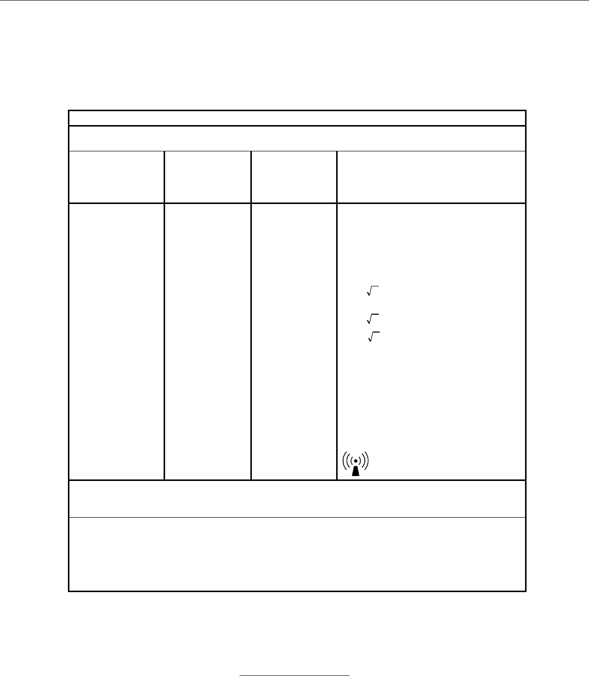
Stasis Monitoring System User’s Guide
Page 88
GPD-0001 Rev B
Table 4 – Guidance and manufacturer’s declaration – electromagnetic immunity –
for all medical electrical equipment and medical electrical systems that are not
life-supporting
Guidance and manufacturer’s declaration – electromagnetic immunity
The Stasis Monitoring System is intended for use in the electromagnetic environment specified below. The customer or the
user of the Stasis Monitoring System should assure that it is used in such an environment.
Immunity test
Error! Reference
source not found.
Error! Reference
source not found.
60601 test level
Compliance level
Electromagnetic
environment – guidance
Portable and mobile RF communications
equipment should be used no closer to any part of
< EUT Name > , including cables, than the
recommended separation distance calculated from
the equation applicable to the frequency of the
transmitter.
Recommended separation distance
Conducted RF
EN 61000-4-6
3 Vrms
150 kHz to 80 MHz
3 V
Pd 2,1=
Radiated RF
EN 61000-4-3
3 V/m
80 MHz to 2,5 GHz
3 V/m
Pd 2,1=
80 MHz to 800 MHz
Pd 3,2=
800 MHz to 2,5 GHz
where P is the maximum output power rating of
the transmitter in watts (W) according to the
transmitter manufacturer and d is the
recommended separation distance in meters (m).
Field strengths from fixed RF transmitters, as
determined by an electromagnetic site survey,a
should be less than the compliance level in each
frequency range.b
Interference may occur in the vicinity of equipment
marked with the following symbol:
NOTE 1 At 80 MHz and 800 MHz, the higher frequency range applies.
NOTE 2 These guidelines may not apply in all situations. Electromagnetic propagation is affected by absorption and reflection
from structures, objects and people.
a Field strengths from fixed transmitters, such as base stations for radio (cellular/cordless) telephones and land mobile radios,
amateur radio, AM and FM radio broadcast and TV broadcast cannot be predicted theoretically with accuracy. To assess the
electromagnetic environment due to fixed RF transmitters, an electromagnetic site survey should be considered. If the
measured field strength in the location in which the < EUT Name > is used exceeds the applicable RF compliance level
above, the < EUT Name > should be observed to verify normal operation. If abnormal performance is observed, additional
measures may be necessary, such as reorienting or relocating the < EUT Name > .
b Over the frequency range 150 kHz to 80 MHz, field strengths should be less than 3 V/m.
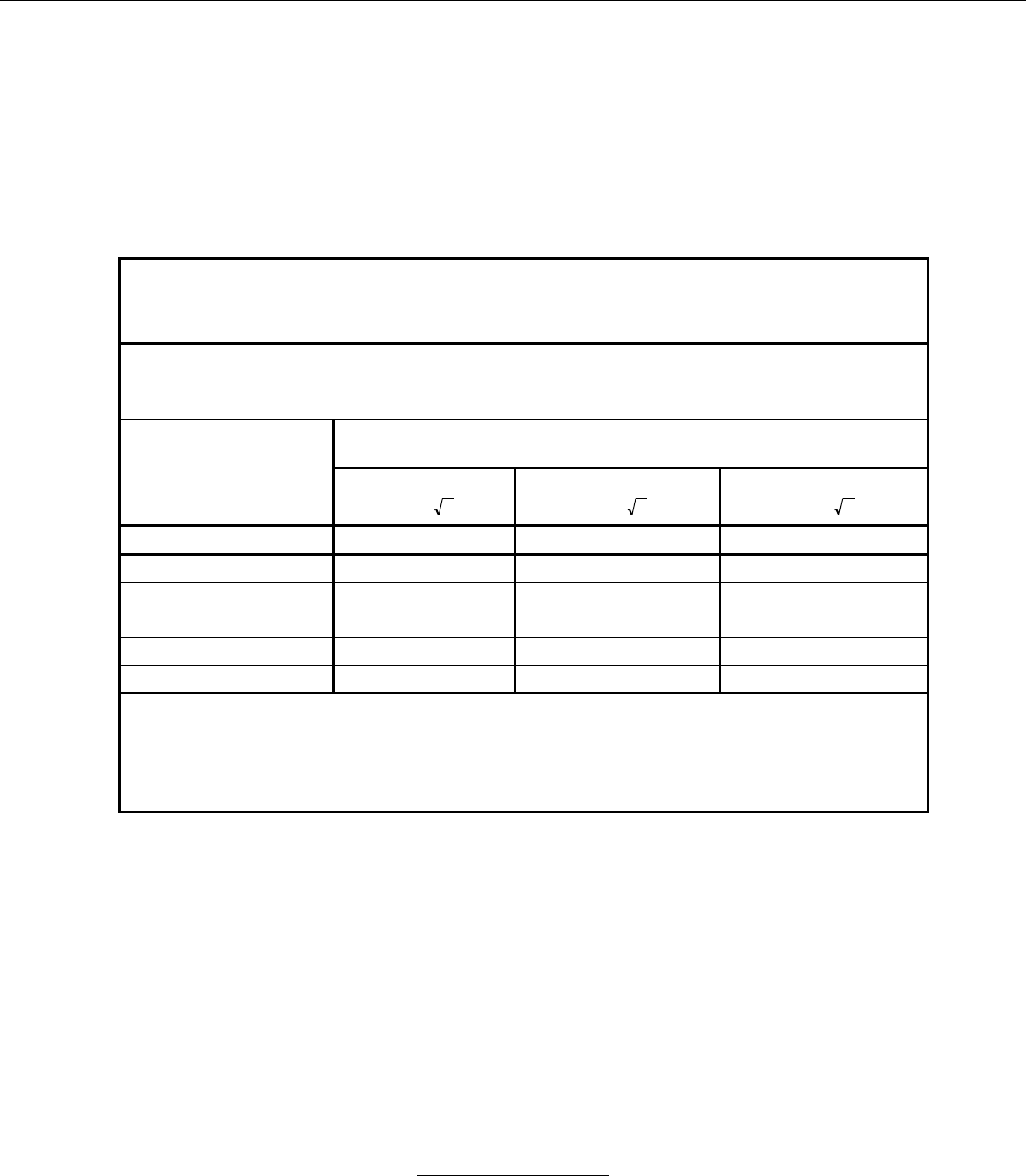
Stasis Monitoring System User’s Guide
Page 89
GPD-0001 Rev B
Table 6 – Recommended separation distances between portable and mobile RF
communications equipment and the medical electrical equipment and medical electrical
systems – for medical electrical equipment and medical electrical systems that are not
life-supporting
Recommended separation distances between
portable and mobile RF communications equipment and the Stasis Monitoring
System
The Stasis Monitoring System is intended for use in an electromagnetic environment in which radiated RF disturbances are
controlled. The customer or the user of the Stasis Monitoring System can help prevent electromagnetic interference by
maintaining a minimum distance between portable and mobile RF communications equipment (transmitters) and the Stasis
Monitoring System as recommended below, according to the maximum output power of the communications equipment.
Rated maximum output
power of transmitter
W
Separation distance according to frequency of transmitter
m
150 kHz to 80 MHz
Pd 2.1=
80 MHz to 800 MHz
Pd 2.1=
800 MHz to 2,5 GHz
Pd 3.2=
3V
3V/m
3V/m
0,01
0,12
0,12
0,23
0,1
0,38
0,38
0,73
1
1,2
1,2
2,3
10
3,8
3,8
7,3
100
12
12
23
For transmitters rated at a maximum output power not listed above, the recommended separation distance d in meters (m) can
be estimated using the equation applicable to the frequency of the transmitter, where P is the maximum output power rating of
the transmitter in watts (W) according to the transmitter manufacturer.
NOTE 1 At 80 MHz and 800 MHz, the separation distance for the higher frequency range applies.
NOTE 2 These guidelines may not apply in all situations. Electromagnetic propagation is affected by absorption and reflection
from structures, objects and people.
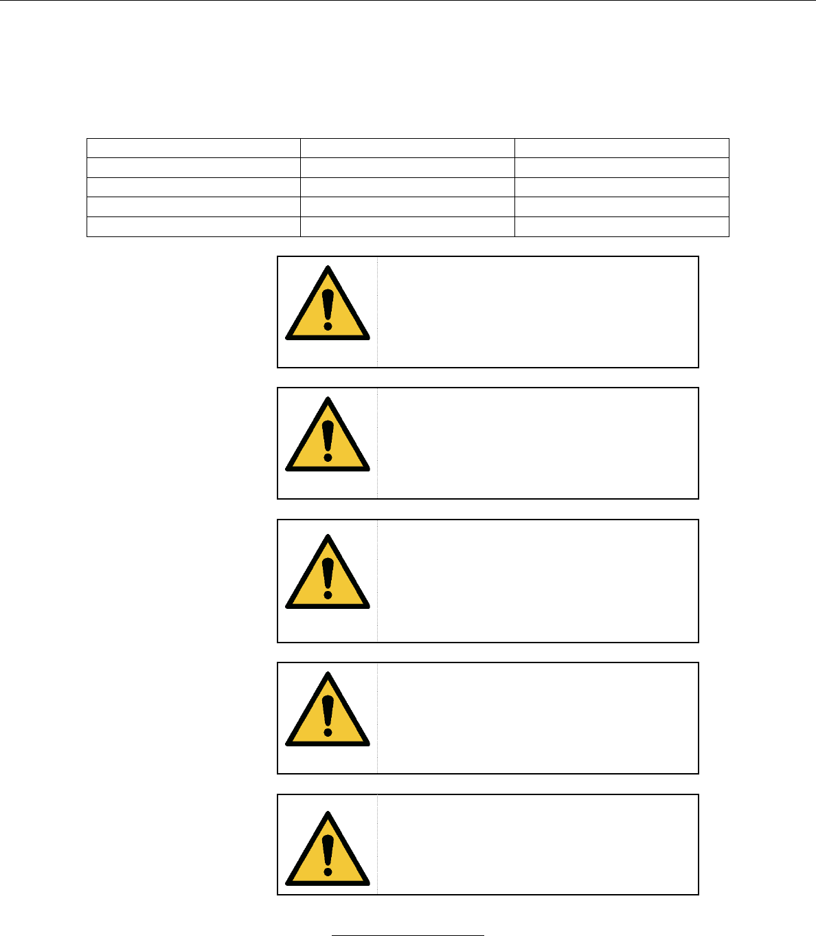
Stasis Monitoring System User’s Guide
Page 90
GPD-0001 Rev B
Cables Used in System:
Cable
Part Number
Length
SpO2 Cable
U410-147
3 m
ECG Cable
EA021S3I
3 m
Temperature Cable
T2252-AS
3 m
Power Cable
1899240
3 m
WARNING
The use of cables other than those specified
may result in increased emissions or
decreased immunity of the ME equipment or
ME system.
WARNING
Do not use the SMS in a MRI suite.
WARNING
The ME equipment or ME system should not
be used adjacent to or stacked with other
equipment, and that if adjacent or stacked
use is necessary, the ME equipment or ME
system should be observed to verify normal
operation in the configuration in which it will
be used.
WARNING
Use of accessories, transducers, or cables
with ME equipment and ME systems other
than those specified may result in increased
emissions or decreased immunity of the ME
equipment or ME system.
The Stasis Monitor may be interfered with by
other equipment, even if that other equipment
complies with CISPR EMISSION
requirements.
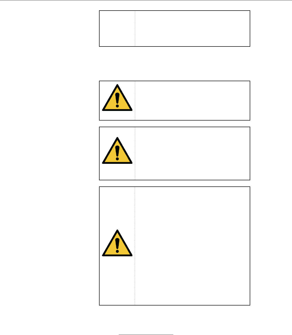
Stasis Monitoring System User’s Guide
Page 91
GPD-0001 Rev B
WARNING
WARNING
Portable and mobile RF communications
equipment may affect the function of the
Stasis Monitoring System.
WARNING
This equipment/system is intended for use by
healthcare professionals only. This
equipment/system may cause radio
interference or may disrupt the operation of
nearby equipment. It may be necessary to
take mitigation measures, such as re-
orienting or relocating the Stasis Monitoring
System or shielding the location.
WARNING
Field strengths from fixed transmitters, such
as base stations for radio (cellular/cordless)
telephones, WIFI-enabled devices, and land
mobile radios; amateur radios; AM and FM
radio broadcast; and TV broadcast, and WIFI
transmission cannot be predicted theoretically
with survey accuracy. To assess the
electromagnetic environment due to fixed RF
transmitters, an electromagnetic site survey
should be considered. If the measured field
strength in the location in which the SMS is
used exceeds the applicable RF compliance
level described in this section, the SMS
should be observed to verify normal
operation. If abnormal performance is
observed, additional measures may be
necessary, such as re-orienting or relocating
the SMS.
Stasis Monitoring System User’s Guide
Page 92
GPD-0001 Rev B
NOTE
These guidelines may not apply in all
situations. Electromagnetic propagation is
affected by absorption and reflection from
structures, objects, and people.
FCC Compliance Statements
This device complies with part 15 of the FCC Rules. Operation is subject to the
following two conditions:
1. This device may not cause harmful interference, and
2. This device must accept any interference received, including interference that may
cause undesired operation.
CAUTION
Any changes or modifications not
expressly approved by the party
responsible for compliance could void the
user's authority to operate this equipment.
CAUTION
This equipment should be installed and
operated with minimum distance 20 cm
between the radiator and your body.
Part 15B Compliance Statements for Digital Devices:
NOTE
This equipment has been tested and found to
comply with the limits for a Class B digital
device, pursuant to part 15 of the FCC Rules.
These limits are designed to provide
reasonable protection against harmful
interference in a residential installation.
This equipment generates, uses, and can radiate radio frequency energy and, if
not installed and used in accordance with the instructions, may cause harmful

Stasis Monitoring System User’s Guide
Page 93
GPD-0001 Rev B
interference to radio communications. However, there is no guarantee that interference
will not occur in a particular installation.
If this equipment does cause harmful interference to radio or television reception,
which can be determined by turning the equipment off and on, the user is encouraged to
try to correct the interference by one or more of the following measures:
• Reorient or relocate the receiving antenna.
• Increase the separation between the equipment and receiver.
• Connect the equipment into an outlet on a circuit different from that to which the
receiver is connected
• Consult the dealer or an experienced radio/TV technician for help.
XIII. TECHNICAL SUPPORT
A. If you believe that your system is malfunctioning, contact Stasis at
contact@stasislabs.com for instructions on returning your current system
and receiving a replacement.
Manufacturer: Stasis Labs, Inc.
Model: Stasis Monitoring System
Address: 9121 Airdrome St., Los Angeles, CA 90035
XIV. RECORDS
REVISION
SIGNIFICANT CHANGES
DCO#
EFFECTIVE
DATE
A
Initial release
0034
1/4/18
B
See redlined
0053
1/17/18