Stealth Alarm Systems SIU3A Radio Alarm Transmitter User Manual SIU3 Manualv2
Stealth Alarm Systems Inc Radio Alarm Transmitter SIU3 Manualv2
UserManual.wiki
>
Stealth Alarm Systems
>
SIU3A User Manual
Users Manual Revised
Navigation menu
Upload a User Manual
Namespaces
Wiki Guide
HTML
PDF
Info
Views
User Manual
Discussion / Help
Navigation

![8 operation The TEL-KEY-360 provides complete system status operation, including Tela-Link™ (TLR) zone status and trouble condition information. The keypad is also used to program the Tela-Link™ (TLR) reporting codes and system options. The keypad’s zone lights provide alarm and status indication for the alarm circuits. When the [*] key is pressed, the zone lights are used to display trouble conditions. Note: that the keypad connected to the Tela-Link™ (TLR) is only used to program and display information from the TLR unit. The keypad connected to the TLR cannot operate or display system information from an alarm control panel connected to the TLR. If the TLR is connected to a security system, the keypad should be removed once the TLR has been programmed. normal operation During normal operation, the 360 keypad will be in the “Ready Mode” with the “Ready” light illuminated. Activity on the TLR zone terminals (terminals Z1 through Z6) will be indicated on the Zone Lights; when a zone is activated, the Zone Light will come ON. If a TLR trouble condition is detected, the ‘Trouble” light will come ON. Press [*] to view trouble conditions. Note that the zones on the TLR are “armed” at all times. Trouble Display The Tela-Link™ (TLR) continuously monitors for four trouble conditions. If one of these conditions occurs, the keypad “Trouble Light” will come ON and the keypad will sound two short beeps every 10 seconds. To silence the buzzer, press the [#] key; the sounder will be silenced but the “Trouble Light” will remain ON until the trouble condition is cleared. Trouble conditions may be reported to the monitoring station by programming alarm and restoral reporting codes in Sections [08] and [09]. To view the trouble condition, press[*]. Trouble conditions will be indicated on the keypad Zone Lights: Zone Light [1] Internal Low Voltage Trouble: If the DC supply to the Tela-Link™ (TLR) drops below 10.9VDC for more than 4 minutes, this trouble will be indicated. This trouble condition will only be cleared after the DC supply voltage returns to 11.6 VDC or higher for more than 4 minutes. NOTE: The Tela-Link™ (TLR) will not power up with a low voltage from the power supply. Ensure that a 12Vdc supply is connected to the Tela-Link™ (TLR). [2] Loss of Time Trouble: This trouble condition will be displayed when the Tela-Link™ (TLR) is powered up after having lost power. This](https://usermanual.wiki/Stealth-Alarm-Systems/SIU3A/User-Guide-685101-Page-8.png)
![9condition will only be displayed if a Test Transmission time is programmed. This trouble will be cleared after trouble conditions are displayed and the display mode is exited, or after the system clock is reset. To exit the trouble display mode, press the [#] key. If [9] is pressed while in the trouble display mode, the most recent trouble will be displayed on the zone lights. This trouble memory is useful as a diagnostic tool when installing and servicing the Tela-Link™ (TLR). OUT TRBL Terminal When a trouble condition is generated, the OUT TRBL terminal will switch to ground and will remain switched until the trouble condition is cleared. This output may be used to activate a trouble indicator, such as an LED indicator, a low current sounder, or an RM-1 relay connected to another device. The OUT TRBL terminal may also be connected to a zone terminal on a security control panel to report TLR trouble conditions to the security system. programming Tela-Link is fully programmed in the Universal panel, programmed in 6x2 formatting. Enter the Installer’s code. The default Installer’s Code is the code that may be changed in Programming Section [11]. When the Installer’s Code is entered, the “Armed” light will come ON and the “Program” light will FLASH. The Tela-Link™ (TLR) is now ready to be programmed. To exit the programming mode and return to the “Ready” mode, press the [#] key. NOTE: If no key is pressed for more than two minutes, the Tela-Link™ (TLR) will return to the Ready mode and the Installer’s code will have to be entered again. With the “Armed” light ON steady, enter two digits for the section to be programmed. Programming sections range form[01] to [14], and special sections [90], [91] and [99]. Each section may be programmed individually. Once the desired section has been entered, the “Armed” light will be shut OFF, the “Ready” light will be ON, and the “Program” light will FLASH. The keypad will also beep 3 times. Programming data may now be entered. Programming Data Most sections contain groups of 2-digit entries. The keypad will beep twice after each 2-digit group is entered. When a section is entered, Zone Lights 1 through 4 will indicate, in binary format, the value of the first digit in the section; refer to the Binary Data Display Chart. If you wish to change that digit, simply enter the new digit. If you wish to keep that digit unchanged, you can enter the same number or skip over the digit. Hexadecimal numbers may also be entered in most sections. Refer to the Hexidecimal Data Programming for instruction on programming hex data. When the first digit has been entered or skipped, the Zone Lights will display the value of the next digit. After each digit is entered or skipped, the Zone Lights show the value of the next digit. When all data for a section is entered or reviewed, the keypad will beep several times and the “Armed” light will come ON and the “Ready” light will be shut OFF. At this point, you will be in the program mode. Enter the 2- digit number of the next section to be programmed. It is not necessary to program all 2-digit pairs in a section. A section can be entered and selectively programmed by going only to the digit or digits you wish to change, and then pressing [#] to return to the programming mode.](https://usermanual.wiki/Stealth-Alarm-Systems/SIU3A/User-Guide-685101-Page-9.png)
![10HEX Diagram For 2-digit numbers, both digits must be programmed before pressing the [#] key. Only the data entered before pressing the [#] key will be changed. Section [10] System Configuration Section [10] allows system options to be enabled or disabled. Section [10] uses the Zone Lights to indicate which options are selected; press the corresponding number keys to turn the options ON and OFF. When section [10] is entered, Zone Lights 1 to 6 will display which option are selected. Pressing the number key corresponding to the option’s Zone Light will alternately turn light ON and OFF. All lights can be turned OFF at once by pressing [0]. When the option selections have been made, press [#] to save the selections in memory and return to the program mode. Binary Data Display Zone Lights 1 through 4 are used to display the binary value of the data. Reviewing Programmed Data • Enter the section to be programmed by entering the 2- digit section number. • Zone Lights 1 through 4 will represent the value, in binary format, of the first digit in the section. • Press the [F] key to advance the display to the next digit. • At the end of the section, the keypad will beep several times and then return to the Program Mode so that another section can be selected for review or programming. HEX Data Programming Certain programming sections may require the entry of data in HEX (hexadecimal, or base 16) format. HEX numbering uses the numbers 0 through 9 and the letters A through F. The letters A through F are represented by the number keys 1 through 6. To enter data in HEX format, first press the [*] key; the “Ready” light will FLASH. Press a number key from [1] to [6] to enter a HEX digit. The “Ready’ light will stop flashing, indicating that the next keypress will enter a decimal value. To enter HEX numbers:](https://usermanual.wiki/Stealth-Alarm-Systems/SIU3A/User-Guide-685101-Page-10.png)
![11 A....... Enter [*][1] B....... Enter [*][2] C....... Enter [*][3] D....... Enter [*][4] E....... Enter [*][5] F....... Enter [*][6] When the “Ready” light is ON STEADY: data is entered in decimal When the “Ready” light is FLASHING: data is entered in HEX If the [*] key is pressed accidentally while entering data, press the [*] key a second time to exit the HEX data entry mode. programming sections [01] Radio Account Code [2150-SUI1] [1834-SUI2] This 4-digit code is used to identify the system and is transmitted when the Tela-Link™ (TLR) initiates communications. This can be viewed on the CPU label or this section through the TEL-KEY-360 this has been pre-programmed and is not changeable. [02] Alarm Reporting Codes, Zones 1 to 6 Enter eight 2-digit codes for the Alarm Reporting Codes for the Tela-Link™ (TLR) zones. These codes are used to report alarms on zones 1 through 6. [03] Restoral Reporting Codes, Zones 1 to 6 Enter eight 2-digit codes for the Restoral Reporting Codes for the Tela-Link™ (TLR) zones. These codes are used to report restorals in zones 1 through 6. [04] Maintenance Alarm Reporting Codes Program 2-digit alarm reporting codes for the following trouble conditions and the test transmission: • Internal Low Voltage Trouble This code will be transmitted when the voltage supplied to the Tela-Link™ (TLR) at the +12V and -12V terminals drops to 10.9Vdc or less for more then 4 minutes. This trouble will be restored when the voltage returns to 11.6 Vdc or higher for more than 4 minutes. • Test Transmission This code will be transmitted at the time and at the interval programmed in Section [12]. Enable the Test Transmission function in Section [10]. [05] Maintenance Restoral Reporting Codes Program 2-digit restoral reporting codes for the following trouble conditions: • Internal Low Voltage Trouble Restoral](https://usermanual.wiki/Stealth-Alarm-Systems/SIU3A/User-Guide-685101-Page-11.png)
![12Refer to Section [04] for information on the maintenance alarm reporting codes and the conditions that will cause them to be transmitted. [10] System Configuration The system Configuration is set using the Zone Lights as shown in the table below. Once Section [10] is entered, the 6 zone lights will indicate the status of each option. Press the number key corresponding to the zone light to turn an option ON and OFF. Press [0] to turn all the zone lights OFF. Zone Light 1 Communications Disabled. The Tela-Link™ (TLR) will not initiate long-range radio communications when alarm events occur or when data is received from the control panel. Disable communications to test the system and monitor zone activity on the keypad. DEFAULT Communications Enabled. The Tela-Link™ (TLR) will initiate radio communications when alarm events occur or when data is received from the control panel. Zone Light 2 ON 60 Second Zone Bypass on Power-up. The alarm zones on the Tela-Link™(TLR) (terminals Z1 through Z6) will be temporarily bypassed for 60 seconds after power is applied to the system. This allows time for the detection devices to “settle” after power is applied, and is intended to prevent false alarms. OFF Zones Active on Power-up. The alarm zones on the Tela-Link™ (TLR) will be active immediately when power is applied to the system. Zone Light 3 ON Test Transmission Disabled. The test transmission function will not operate. DEFAULT Test Transmission Enabled. The Tela-Link™ (TLR) will transmit the RF Identification Code and the Test Transmission Reporting Code at the time and interval programmed in Section [12]. NOTE: A Test Transmission Code in Section [08] and a Test Transmission Time and Interval in Section [12] must be programmed to enable the Test Transmission. Zone Light 4 ON For future use.](https://usermanual.wiki/Stealth-Alarm-Systems/SIU3A/User-Guide-685101-Page-12.png)
![13 DEFAULT The Tela-Link™ (TLR) is to be used in a stand-alone application. Zone Light 5 ON Negative Trigger Zone Inputs. All zone inputs require a negative trigger to activate. Refer to the Hook-up Diagram for instructions on connecting negative trigger zones. OFF Positive Trigger Zone Inputs. All zone inputs require a positive trigger to activate. Refer to the Hook-up Diagram for instructions on connecting negative trigger zones. Zone Light 6 ON For future use. OFF For future use. Zone Light 7 ON For future use. OFF For future use. Zone Light 8 ON For future use. OFF For future use. [11] Installer’s Code Program a 4-digit code in this Section. Only use digits 0 through 9 as numbers in the code. If an error is made entering the code, complete entry of the 4 digits then enter the section number again to enter the correct code. [12] System Times Program the following times in this section; all times are programmed in the range from “0” to “99”. • Test Transmission (hours). Program the hour of the Test Transmission in the 24-hour clock format. Enter a time from “00” to “23”, where “00” is 12:00 midnight, and 23 is 11:00 pm. • Test Transmission (minutes). Program the minutes of the Test Transmission time. Enter a time from “00” to “59” minutes. • Test Transmission Interval (days). Program the interval, in days, at which test transmissions will be performed. The default setting is 30 days. • Zone Response Time (x10 ms). This value determines the zone response time in milliseconds (ms). The response time is programmed in increments of 10 milliseconds, from a minimum of 0.02 seconds (20 milliseconds) to a maximum of 0.99 seconds (990 milliseconds). The default zone response time is 500 ms. i.e.: HH/MM/DD/SS = 13/45/30/30 [13] System Clock Enter the time of day using the 24-hour clock format. Enter”00” to “23” for the hour, and “00” to “59” for the minute. If this section is not programmed, the Tela-Link™ (TLR) will automatically set its clock as “00:00”.](https://usermanual.wiki/Stealth-Alarm-Systems/SIU3A/User-Guide-685101-Page-13.png)
![14The system time is transmitted along with all event transmissions. It is recommended that the system clock always be programmed with the correct time. NOTE: The system clock will need to be reprogrammed whenever power is removed from the Tela-Link™ (TLR), or if the Tela-Link™ (TLR) is reset to the factory default programming. i.e.: HH/MM [14] System Date Enter the current date as MMDDYY, where MM is the month (“01” to “12”), DD is the date (“01” to “31”), and YY is the year (“00” to “99”). If this section is not programmed, the Tela-Link™ (TLR) will automatically set its date as “00:00:00”. i.e.: MM/DD/YY [14] System Date Continued… The system date is transmitted along with all event transmissions. It is recommended that the system date always be programmed with the correct date. NOTE: The system date will need to be reprogrammed whenever power is removed from the Tela-Link™ (TLR), or if the Tela-Link™ (TLR) is reset to the factory default programming. [90] Installer Lockout Enable When this feature is enabled, performing a hardware or software reset to restore the system’s factory programming will not reset the Installer’s Code. To enable the Installer’s Lockout, enter Section [90]. After entering Section [90], the keypad will beep 6 times. To indicate that the Installer Lockout feature has been enabled, the Tela-Link™ (TLR) will beep the keypad sounder 10 times when power is applied to the Tela-Link™ (TLR). Ensure that the new Installer’s Code has been entered correctly before enabling the Installer’s Lockout. Without the correct Installer’s Code, there is no way of entering the Programming Mode. [91] Installer Lockout Disable Entering section [91] while in the Installer’s Programming Mode will disable the Installer Lockout feature described in Section [90]. To disable the Installer’s Lockout, enter Section [91]. After entering section [91], the keypad will beep 6 times. NOTE: Units returned to Tela-Link Communications with the Installer Lockout feature enabled and no other apparent problems will be subject to an additional service charge [$25/Panel+S&H]. [99] Restore Factory Default Programming Enter this section to reset the system’s programming to the factory default settings. To enable this feature, enter Section [99]. After entering section [99], the keypad will beep 6 times and the “Program”](https://usermanual.wiki/Stealth-Alarm-Systems/SIU3A/User-Guide-685101-Page-14.png)
![15light will come on briefly. The keypad will then beep 6 or 10 times to indicate if the Installer’s Lockout feature has been disabled or enabled. The Tela-Link™ (TLR)’s factory programming has now been restored. Hardware Reset If the Installer’s Code has been forgotten, the Tela-Link™ (TLR) may be reset using the following method: 1. Disconnect the power supply 2. Disconnect any connections made to the LB TRBL and TRBL OUT terminals 3. Use a jumper to short the LB TRBL and TRBL OUT terminals 4. Apply power to the Tela-Link™ (TLR) 5. Wait for 10 seconds, then remove the jumper 6. The Tela-Link™ (TLR) programming will now be restored to the factory default settings If the Installer’s Lockout has been enabled, resetting the Tela-Link™ (TLR) to the factory programming will not restore the default Installer’s Code. A $25+S&H charge will be applied to dealer to unlock installer’s lockout. programming worksheets [01] Tela-Link™ Unit I.D. (SIU3 = Use All 6 digits for I.D. Entry) [02] Alarm Reporting Codes, Zones 1 to 6 / Open - Red Light ON [___][___] Zone 1 Alarm [___][___] Zone 2 Alarm [___][___] Zone 3 Alarm [___][___] Zone 4 Alarm [___][___] Zone 5 Alarm [___][___] Zone 6 Alarm [03] Restoral Reporting Codes, Zones 1 to 6 / Closes - Red Light OFF [___][___] Zone 1 Alarm [___][___] Zone 2 Alarm [___][___] Zone 3 Alarm [___][___] Zone 4 Alarm [___][___] Zone 5 Alarm [___][___] Zone 6 Alarm [04] For Future Use. [05] For Future Use. [06] For Future Use. [07] For Future Use. [08] Maintenance Alarm Reporting Codes](https://usermanual.wiki/Stealth-Alarm-Systems/SIU3A/User-Guide-685101-Page-15.png)
![16 [___][___] Internal Low Voltage Trouble [___][___] External AC Trouble [___][___] External Low Battery Trouble [___][___] Control Panel Connection Trouble [___][___] Test Transmission [09] Maintenance Restoral Reporting Codes [___][___] Internal Low Voltage Trouble Restore [___][___] External AC Trouble Restore [___][___] External Low Battery Restore [___][___] Control Panel Connection Trouble Restore Do not enter hexadecimal numbers in this section. An Account Code must be entered before communications through the Tela-Link™ can be used. To disable any reporting code, enter [00] or [*][6][*][6] (hexadecimal FF). [10] System Configuration Default Light ON OFF OFF [___] 1 Communications disabled Communications enabled ON [___] 2 60-second bypass on power-up Zones active on power-up OFF [___] 3 Test transmission disabled Test transmission enabled OFF [___] 4 Future Use - enabled Future Use - disabled OFF [___] 5 Negative trigger zone inputs Positive trigger zone inputs OFF [___] 6 For Future Use For Future Use OFF [___] 7 For Future Use For Future Use OFF [___] 8 For Future Use For Future Use [11] Installer’s Code Default [ 2 ] [ 1 ] [ 5 ] [ 0 ] [___][___][___][___] Version: SIU1 Program a 4-digit code using the numbers [0] through [9]. Default [ 1 ] [ 8 ] [ 3 ] [ 4 ] [___][___][___][___] Version: SIU2 & SIU3 Program a 4-digit code using the numbers [0] through [9]. [12] System Times Default [ 9 ][ 9 ] [___][___] Test Transmission (hours) [ 9 ][ 9 ] [___][___] Test Transmission (minutes) [ 3 ][ 0 ] [___][___] Test Transmission Interval (in days)](https://usermanual.wiki/Stealth-Alarm-Systems/SIU3A/User-Guide-685101-Page-16.png)
![17 [ 5 ][ 0 ] [___][___] Zone Response Time (x 10 ms) Test Transmission Interval must not be programmed as [00]. Zone Response Time must be in the range of [02] to [99]; do not program [00] or [01]. [13] System Clock Enter the time in the 24-hour clock format (HHMM) [14] System Date Enter the date as 2 digits each for the Month, Day and Year (MMDDYY) [90] Installer’s Lockout Enable [91] Installer’s Lockout Disable [99] Restore Factory Default programming telA-link communications siu3 Hook Up Diagram UNIVERSAL](https://usermanual.wiki/Stealth-Alarm-Systems/SIU3A/User-Guide-685101-Page-17.png)

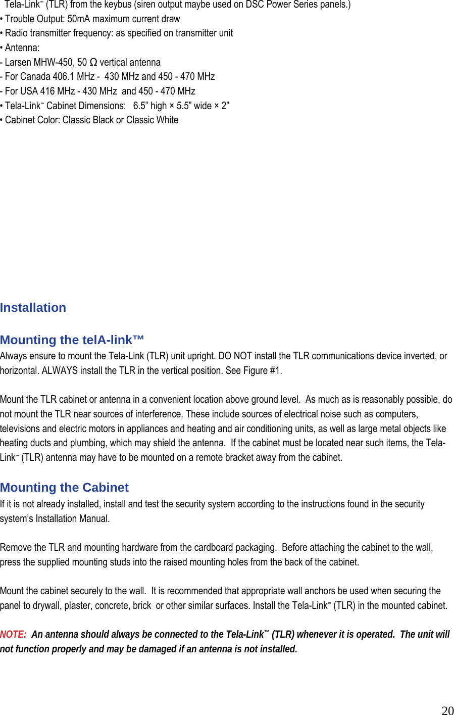
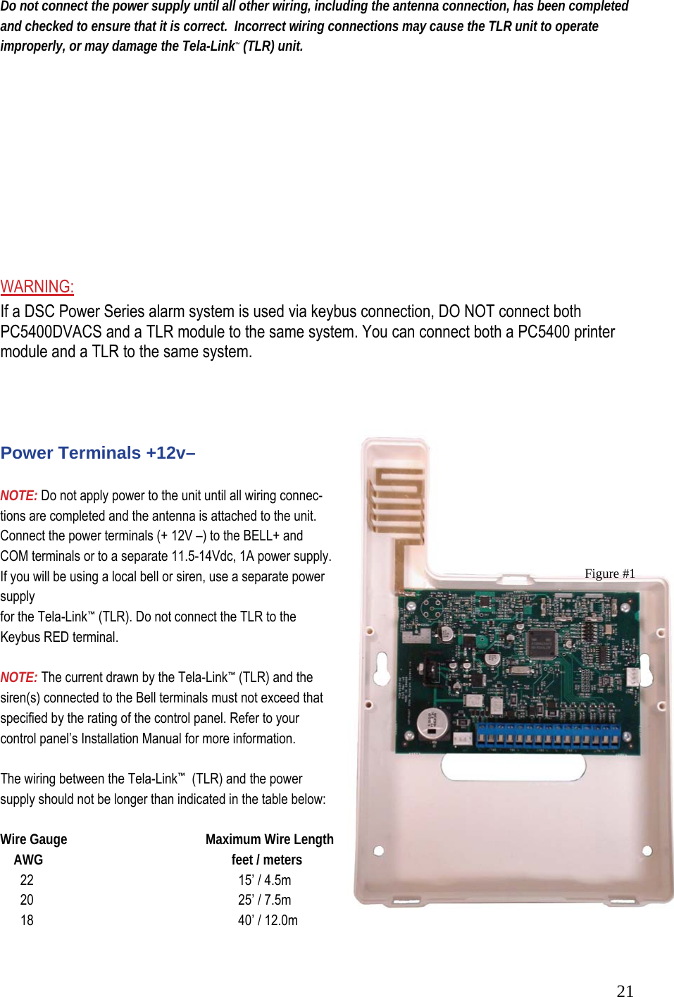
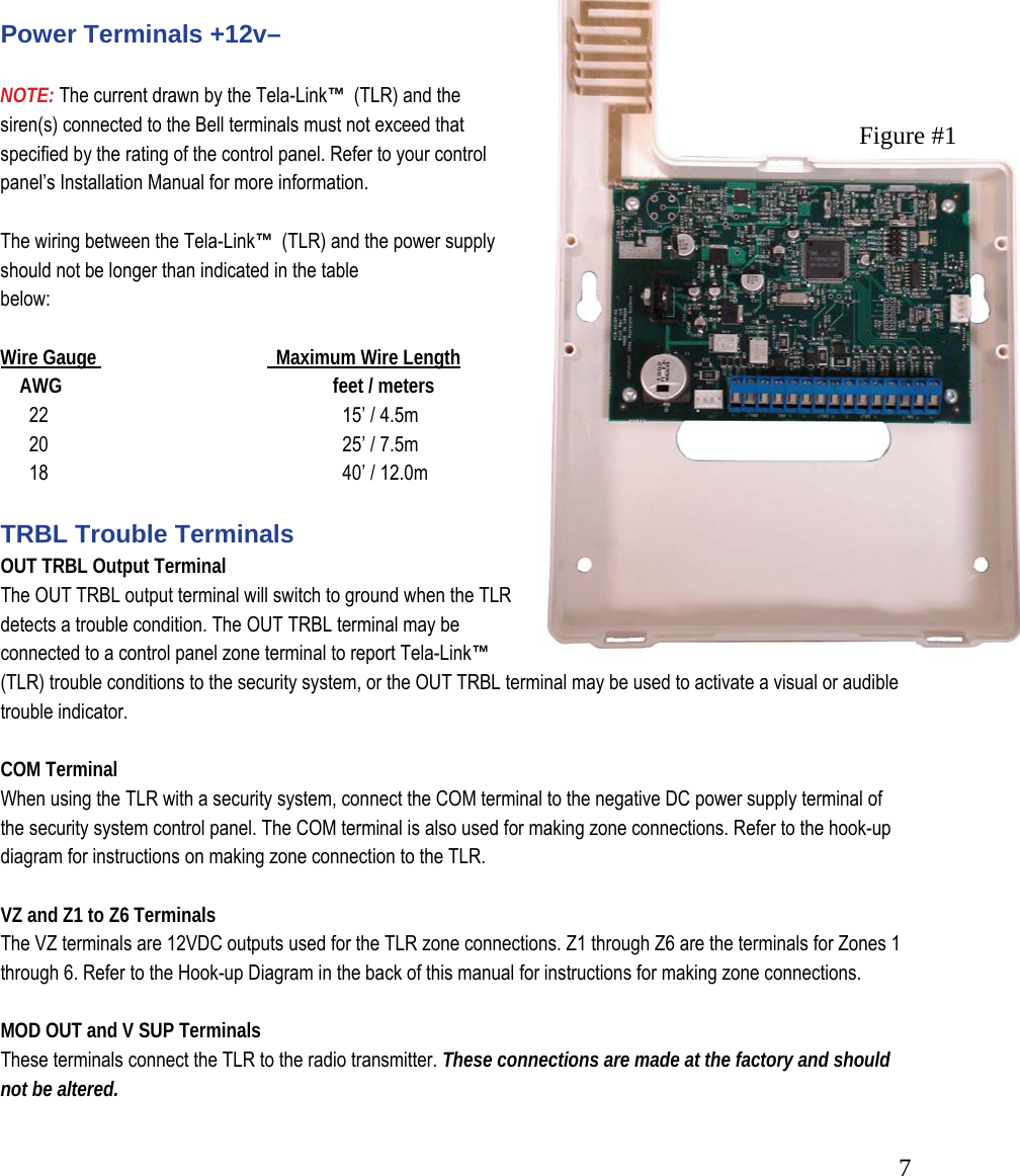
![22 You can double the maximum wire length if you double the conductors and connect them in parallel. Mount the TLR as close to the power supply as possible. TRBL Trouble Terminals OUT TRBL Output Terminal The OUT TRBL output terminal will switch to ground when the TLR detects a trouble condition. The OUT TRBL terminal may be connected to a control panel zone terminal to report Tela-Link™ (TLR) trouble conditions to the security system, or the OUT TRBL terminal may be used to activate a visual or audible trouble indicator. This output may be used to activate a trouble indicator, such as an LED indicator, a low current sounder, or relay connected to another device. COM Terminal When using the TLR with a security system, with sufficient power, connect the COM terminal to the negative DC power supply terminal of the security system control panel. YEL and GRN Keypad Terminal The GRN KEYPAD terminal is used to connect the keybus green from the PANEL. The YEL KEYPAD terminal is not used. Keybus Connections Panel Tela-Link Bell+ Red - 12 + Keybus Black To AUX- Keybus Green To GRN Keybus Yellow To YEL Note: Do not connect the Keybus RED wire to the Tela-Link™ (TLR). Programming the telA-link™ Program the Tela-Link™ (TLR) through Installer’s Programming at a system keypad, or downloading software. For instructions on keypad programming using Installer’s Programming sections, please refer to section 4 “How to Program” in your control panel Installation Manual. To enter Installer’s programming: 1. Go to Installer’s Programming by entering [*][8][Installer’s code]. 2. For PC5015, PC5010, PC1555 and PC580: Go to the Tela-Link™ (TLR) programming section by entering [803]. For PC1575: Go to the Tela-Link™ (TLR) programming section by entering [86].](https://usermanual.wiki/Stealth-Alarm-Systems/SIU3A/User-Guide-685101-Page-22.png)
![23 Programming Data Most sections contain groups of 2-digit entries. The keypad will beep twice after each 2-digit group is entered. When a section is entered, on LED keypads, zone lights 1 through 4 will indicate, in binary format, the value of the first digit in the section. If you wish to change the digit displayed, enter the new digit. If you wish to keep that digit unchanged, skip over the digit by pressing the [F] Key. Hexadecimal numbers may also be entered in most sections. Refer to Hexadecimal Data Programming for instructions. When you are done programming the section, enter the 2-digit number of the next section to be programmed. Reviewing Programmed Data • Enter the 2-digit number of the section to be reviewed. • LCD keypads will display the current data in the programming section. • LED keypads will display the first digit of data in the section using zone lights 1 to 4 to represent the ] value, in binary format. To advance the display to the next digit, press the [F] key. • At the end of the section, the keypad will beep several times and then return to the Program Mode so that another section can be selected for review or programming. hex Data Programming Certain programming sections may require the entry of data in HEX (hexadecimal, or base 16) format. HEX numbering uses the numbers 0 through 9 and the letters A through F. The letters A through F are represented by the number keys 1 through 6. To enter data in HEX format, first press the [*] key. Press a number key from [1] to [6] to enter a HEX digit then press the [*] key again to return to “decimal” values. To enter HEX numbers: A.......Enter [*][1][*] B.......Enter [*][2][*] C.......Enter [*][3][*] D.......Enter [*][4][*] E.......Enter [*][5][*] F.......Enter [*][6][*] telA-link™ (tlr) Programming Sections These sections will only be available if a TLR v2.0 (SUI3) is connected to the Keybus. [86] Tela-Link™ (TLR) Programming Sections for PC1575](https://usermanual.wiki/Stealth-Alarm-Systems/SIU3A/User-Guide-685101-Page-23.png)
![24 or [803] Tela-Link™ (TLR) Programming Section for PC5010, PC5015, PC1555, PC580 [01] TLR Account Code This 6-digit code is used to identify the system and is transmitted when the TLR initiates communications. Program a 6-digit code in this section using only numbers from 0 to F. Note: An account number must be entered in this section before communications through the Tela-Link™ (TLR) can be used. Do not enter Hexadecimal numbers in this section. [10] maintenance Alarm Reporting Codes Program 2 digit reporting codes for each of the following reporting codes • Internal Low Voltage This code will be sent when the voltage supplied to the Tela-Link™ (TLR) on the 12+ and 12 - terminals is less then 10.5 VDC for more than 4 minutes • External AC Trouble This code will be sent when the AC TRBL input terminal is switched to ground. • External Low Battery Trouble This code will be sent when the LB TRBL input terminal is switched to ground. • Control Panel Connection Trouble This code will be sent when connection is lost to the panel on the Keybus for more than 60 seconds • Test Transmission This code will be sent at the same interval as the test transmission of the panel. [11] maintenance Restoral Reporting Codes Program 2 digit reporting codes for each of the following reporting codes • Internal Low Voltage This code will be sent when the voltage supplied to the Tela-Link™ (TLR) on the 12+ and 12 - terminals is restored to more than 11.6 VDC for more than 4 minutes. • External AC Trouble This code will be sent when the AC TRBL input terminal is switched to ground. • External Low Battery Trouble This code will be sent when the LB TRBL input terminal is switched to ground. • Control Panel Connection Trouble This code will be sent when connection is restored to the panel on the Keybus for more then 60 seconds.](https://usermanual.wiki/Stealth-Alarm-Systems/SIU3A/User-Guide-685101-Page-24.png)
![25 [20] module Configuration Module configuration is set using Zone Lights as shown below. After you enter section [20], the options that are “on” will be shown either by the corresponding zone light being on (LED keypads) or the zone number being displayed (LCD keypads). Press the corresponding number key to turn an option ON or OFF. When finished, press [#]. Zone Light 1 ON - Communications Enabled - The Tela-Link™ (TLR) will initiate communications for all events that the panel has reporting codes programmed for. OFF - Communications Disabled - The Tela-Link™ (TLR) will not initiate communications for events that the panel has reporting codes programmed for. Disable communications to test the system. Zone Light 2 OFF - TRBL OUT Normally High Impedance - If there are no trouble conditions detected by the Tela-Link™ (TLR), the TRBL OUT terminal will be high-impedance. The TRBL OUT terminal will switch to ground when the Tela-Link™ (TLR) detects a trouble condition. ON - TRBL OUT Normally Low - If there are no trouble conditions detected by the Tela-Link™ (TLR), the TRBL OUT terminal will be low (ground). The TRBL OUT terminal will switch to high-impedance when the Tela-Link™ (TLR) detects a trouble condition. Zone Light 3 to Zone Light 8 INACTIVE ZONES - DSC & Visonic Panel ACTICE ZONES - Six (6) discrete zones for any panel beside listed above.](https://usermanual.wiki/Stealth-Alarm-Systems/SIU3A/User-Guide-685101-Page-25.png)
![26 [30] Call Direction Options Program which of the following reporting code types the TLR will send to the central station. Press the number corresponding the appropriate option to turn the reporting type ON or OFF. When finished, press [#]. Option 1 Alarm/restore reporting 2 Tamper/restore reporting 3 Opening/closing reporting 4 System maintenance reporting 5 System test transmission reporting In most installations, you should program the transmission of alarm/restore reporting codes only. Your radio network, StarNet Radio Communications™, has limited bandwidth and capacity. The more signals each TLR transmits, the fewer TLR’s you will be able to install on your network. NOTE: Sections [81] and [82] apply only to the PC1575 v1.0. All other panels will use the reporting codes that are programmed for these events in the panel. [81] miscellaneous Alarm Reporting Codes Program 2 digit reporting codes for each of the following reporting codes • General Zone Fault Alarm This code will be sent when the Tela-Link™ (TLR) receives a General Zone Fault Alarm event from the PC1575. • General System Tamper Alarm This code will be sent when the Tela-Link™ (TLR) receives a General System Tamper Alarm event from the PC1575. • General System Supervisory Alarm This code will be sent when the Tela-Link™ (TLR) receives a General System Supervisory Alarm event from the PC1575. [82] miscellaneous Restoral Reporting Codes Program 2 digit reporting codes for each of the following reporting codes • General Zone Fault Restoral](https://usermanual.wiki/Stealth-Alarm-Systems/SIU3A/User-Guide-685101-Page-26.png)
![27 This code will be sent when the Tela-Link™ (TLR) receives a General Zone Fault Restoral event from the PC1575. • General System Tamper Restoral This code will be sent when the Tela-Link™ (TLR) receives a General System Tamper Restoral event from the PC1575. • General System Supervisory Restoral This code will be sent when the Tela-Link™ (TLR) receives a General System Supervisory Restoral event from the PC1575. [83] miscellaneous Alarm Reporting Codes (PC1555 v2.0 panel only) Program 2 digit reporting codes for the following (see your PC1555 Installation Manual for more information): • Police Code: This code will be sent when the Tela-Link™ (TLR) receives a Police Code event from the PC1555. • Delinquency Code: This code will be sent when the Tela-Link™ (TLR) receives a Delinquency event from the PC1555. [96] [Installer Code] [96] Restore Tela-Link™ (TLR) Factory Default Programming for PC1575 [993][Installer Code][993] Restore Tela-Link™ (TLR) Factory Default Programming for PC5010 v1.1 or later, PC5015, PC1555, PC580 When this section is successfully entered, all programming in the Tela-Link™ (TLR) will be returned to the factory defaults. NOTE: This command is unavailable on PC5010 v1.0. If v1.0 is used, a hardware default must be done. Hardware Reset On a PC5010 v1.0, a hardware reset must be done. There is no software equivalent for PC5010 v1.0. 1. Remove all power to the Tela-Link™ (TLR) 2. Disconnect all connections made to LB TRBL and TRBL OUT. 3. Use a jumper to short LB TRBL and TRBL OUT terminals. 4. Re-apply power.](https://usermanual.wiki/Stealth-Alarm-Systems/SIU3A/User-Guide-685101-Page-27.png)
![285. Wait 10 seconds then remove the short. NOTE: This can also be done if connected to PC1575. telA-link (tlr) - programming worksheet [86] Tela-Link™ (TLR) Programming Sections for PC1575 OR [803] Tela-Link™ (TLR) Programming Section for PC5010, PC5015, PC1555, PC580 [01] RF (Radio Frequency) Identification Code (Unit I.D.) Default I______I______I______I______I I______I______I______I______I Unit I.D. is a 6-digit code SIU3/Tela-Link#3 = Use All 6 digits [10] Maintenance Alarm Reporting Codes I______I______I Internal Low Voltage Trouble I______I______I External AC Trouble I______I______I External Low Battery Trouble I______I______I Control Panel Connection Trouble I______I______I Test Transmission](https://usermanual.wiki/Stealth-Alarm-Systems/SIU3A/User-Guide-685101-Page-28.png)
![29 [11] Maintenance Restoral Reporting Codes I______I______I Internal Low Voltage Trouble Restore I______I______I External AC Trouble Restore I______I______I External Low Battery Trouble Restore I______I______I Control Panel Connection Trouble Restore [20] Module Configuration Default Option Option ON Option OFF ON I______I 1 Communications enabled Communications disabled OFF I______I 2 TRBL OUT Normally Low TRBL OUT Normally High Impedance OFF I______I 3-8 Future Use Future Use [30]Call Direction Options Default Option ON OFF ON I_______I 1 larm/restore reporting enabled Disabled ON I_______I 2 Tamper/restore reporting enabled Disabled OFF I_______I 3 Opening/closing reporting enabled Disabled ON I_______I 4 System maintenance reporting enabled Disabled ON I_______I 5 System test transmission reporting enabled Disabled OFF I_______I ON 6-8 Future Use [81] Miscellaneous Alarm Reporting Codes I______I______I General Zone Fault Alarm I______I______I General System Tamper Alarm I______I______I General System Supervisory Alarm [82] Miscellaneous Restoral Reporting Codes I______I______I General Zone Fault Restore I______I______I General System Tamper Restore I______I______I General System Supervisory Restore Note: Sections 81 and 82 will be for 1575 v1.0 only. [83] Miscellaneous Alarm Reporting Codes (PC1555 v2.0 panel only) Default = FF I_______I_______I Police Code I_______I_______I Delinquency Code](https://usermanual.wiki/Stealth-Alarm-Systems/SIU3A/User-Guide-685101-Page-29.png)
![30 [96] [Installer Code] [96] Restore Tela-Link™ (TLR) Factory Default Programming for PC1575 [993][Installer Code][993] Restore Tela-Link™ (TLR) Factory Default Programming for PC5010 v1.1 or later, PC5015, PC1555, PC580 HOOK UP FULL REPORTING PANEL](https://usermanual.wiki/Stealth-Alarm-Systems/SIU3A/User-Guide-685101-Page-30.png)