Stealth Alarm Systems SIU3A Radio Alarm Transmitter User Manual SIU3 Manualv2
Stealth Alarm Systems Inc Radio Alarm Transmitter SIU3 Manualv2
Users Manual Revised
1
2
Licensing
The FCC and IC requires the radio to operate with their respective guidelines, this includes licensing. The Stealth Corporation have applied and
received operating licenses within each area the Tela-Link™ units are distributed to within the StarNet coverage placement area.
No further Licensing within those areas are required from the end user. Although the end user / dealer must upon the respective agency request give
immediate access for inspection and testing.
Exposure To Radio frequency energy
The Tela-Link™ transmitter is active when the device senses an alarm event. When the Tela-Link™ transmitter is active it emits up to .6watts (EIRP)
of (RF) radio frequency energy (note this rating includes averaging for duty cycle for RF exposure purposes)
This product has been evaluated for compliance with the maximum permissible exposure for RF energy at the maximum power rating of the unit with
the built in antenna. The antennas used for this device must be installed to provide a separation distance of at least 20 cm (7.9 inches) from the
from all persons and must not be co-located or operating in conjunction with any other antenna or transmitter.
For external antenna connection, the maximum antenna gain must not exceed 5 dBi or FCC/IC compliance will be void
The antenna tested for this product for RF exposure was the StarNet TE-SANT-3. This is the only antenna available through StarNet. Other
antennas may require lesser or greater distances of connector cable to meet the limits depending upon their gains relative to that test. Higher gain
antenna are capable of yielding a higher RF energy density in the strongest part of their field and would, therefore, require a greater separation from
the antenna. If other antennas are used, it is incumbent upon the installer to insure that the RF exposure limits for General Population/Uncontrolled
Exposure are met. See 47CFR1.1307(b)(1)-(3) and / or OET Bulletin 65, Edition 97-01 for more information on RF exposure guidelines.
fcc Label/Warnings
An FCC label must be visible on the units in its final configuration. If the unit is to be used as shipped from StarNet, this would be no problem since
the FCC label is affixed to outside at the bottom of the housing. This label is rate for harsh conditions and is not easily removed or damaged and
contains FCC code UBLSIU3A. Any modifications to this product may void the FCC compliance
Safety Standards
The FCC (with its action in General Docket 79-144, March 1985) has adopted a safety standard for human exposure to radio frequency
electromagnetic emitted by FCC regulated equipment. StarNet observes these guidelines and recommends that you do also:
· DO NOT hold the Tela-Link™ SIU3 so the antenna is very close to or touching exposed parts of the body, especially the face or eyes,
while transmitting.
· DO NOT operate radio equipment near electrical blasting caps or in an explosive atmosphere.
· DO NOT allow children to play with any radio equipment that contains a transmitting device
· REPAIR of Tela-Link™ products should only be performed by StarNet authorized personnel.
General Specifications
FCC ID: UBLSIU3A
IC ID: 6548A-SIU3A
Frequency range Canada: 406.1 - 430 MHz and 450 - 470 MHz
USA: 416 MHz - 430 MHz and 450 – 470 MHz
Bandwidth 6 KHz per spectral mask E
Synthesizer Step Size 6.25 KHz
FCC Rule Parts 90
IC Class RSS-119
RF Channels 1
Frequency Stability < 0.5 PPM (-30 to +50 C)
Data Rate 4800 bps
Power Consumption 12 - 14 VDC or 12 - 17 VAC
Standby 120 mA
Transmit 600 mA
Dimensions 9¼“H x 6¼“W x 2¼“D or 236mmH x 159mmW x 58mmD
Weight 13.8 oz or 390 grams (without battery)
Transmitter Duty Cycle < 1%
Storage Temperature -40 to +85 C, 10% - 90% RHNC
Operating Temperature -30 to +50 C
3
Table of Contents

4

5
features
• Transmits alarm information to a dedicated long-range radio network
• Features Six (6) discrete alarm zones
keypad programmable
FULLY programmed before shipping. The Tela-Link™ (TLR) is complete with a default program and is operational
without programming.
flash memory
The Tela-Link™ (TLR) uses Flash memory, which will retain all program information even if AC and battery power is
removed. The Flash memory can be reprogrammed thousands of times.
Static / Lightning Protection
The Tela-Link™ (TLR) radio network, known as StarNet Radio Communications™, has been carefully designed and
tested to provide reliable protection against static and lightning induced transients. Our special “Zap-Out” circuit board
design catches high voltage transients right at the wiring terminals, and transient protection devices are placed in all
critical areas to further reduce damaging voltages.
Supervision
• Low or disconnected external battery
• Loss of external AC power
• Long-Range Radio Alarm Transmitter
• Six (6) zone inputs for stand-alone operation
• Trouble Reporting Codes and Test Transmission Reporting Code
• Programmable Test Transmission Time
• Programmable zone response time
• Inputs for external power supply trouble indications
• System Clock and Date
• Installer Lockout feature
• Programmed with the TL 360 LED keypad
specifications
• Six (6) positive or negative triggered zone inputs
-positive voltage trigger: 4 to 14 VDC
-negative voltage trigger: 0 to 0.8 VDC
-input impedance: 10kΩ
-maximum zone loop resistance: 100Ω
IMPORTANT:
Alarm Dealers must be enrolled with StarNet Radio Communications to activate a Tela-Link
Transmitter. If you have already enrolled, Please Call 1-888-207-STAR (7827) CANADA or
1-800-246-1914 USA at least 24-hours prior to install.
6
• 2 negative triggered trouble inputs
-negative voltage trigger: 0 to 0.8 VDC
• Output: 50mA
• Programmable with the TL 360 Keypad
installation
Locating the TelA-Link™ (TLR)
Mount the TLR cabinet in a convenient location above ground level. As much as is reasonably possible, do not mount
the TLR near sources of interference. These include sources of electrical noise such as computers, televisions and
electric motors in appliances and heating and air conditioning units, as well as large metal objects like heating ducts
and plumbing, which may shield the antenna. If the cabinet must be located near such items, the Tela-Link™ (TLR)
antenna may have to be mounted on a remote bracket away from the cabinet.
Mounting
Always ensure to mount the Tela-Link unit upright. DO NOT install the Tela-Link communication device inverted, or
horizontal. Always install the Tela-Link in the vertical position. See Figure #1.
Mounting the Cabinet
If it is not already installed, install and test the security system according to the instructions found in the security
system’s Installation Manual.
Mount the cabinet securely to the wall. It is recommended that appropriate wall anchors be used when securing the
panel to drywall, plaster, concrete, brick or other similar surfaces. Install the Tela-Link™ (TLR) in the mounted cabinet.
See Figure #1.
NOTE: An antenna should always be connected to the Tela-Link™ (TLR) whenever it is operated. The unit will
not function properly and may be damaged if an antenna is not installed. Do not connect the power supply
until all other wiring, including the antenna connection, has been completed and checked to ensure that it is
correct. Incorrect wiring connections may cause the TLR unit to operate improperly, or may damage the Tela-
Link™ (TLR) unit.
7
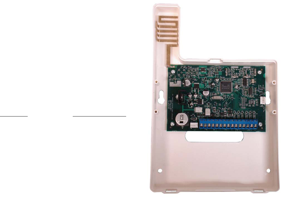
Universal Picture – Figure #1
Power Terminals +12v–
NOTE: The current drawn by the Tela-Link™ (TLR) and the
siren(s) connected to the Bell terminals must not exceed that
specified by the rating of the control panel. Refer to your control
panel’s Installation Manual for more information.
The wiring between the Tela-Link™ (TLR) and the power supply
should not be longer than indicated in the table
below:
Wire Gauge Maximum Wire Length
AWG feet / meters
22 15’ / 4.5m
20 25’ / 7.5m
18 40’ / 12.0m
TRBL Trouble Terminals
OUT TRBL Output Terminal
The OUT TRBL output terminal will switch to ground when the TLR
detects a trouble condition. The OUT TRBL terminal may be
connected to a control panel zone terminal to report Tela-Link™
(TLR) trouble conditions to the security system, or the OUT TRBL terminal may be used to activate a visual or audible
trouble indicator.
COM Terminal
When using the TLR with a security system, connect the COM terminal to the negative DC power supply terminal of
the security system control panel. The COM terminal is also used for making zone connections. Refer to the hook-up
diagram for instructions on making zone connection to the TLR.
VZ and Z1 to Z6 Terminals
The VZ terminals are 12VDC outputs used for the TLR zone connections. Z1 through Z6 are the terminals for Zones 1
through 6. Refer to the Hook-up Diagram in the back of this manual for instructions for making zone connections.
MOD OUT and V SUP Terminals
These terminals connect the TLR to the radio transmitter. These connections are made at the factory and should
not be altered.
Figure #1
8
operation
The TEL-KEY-360 provides complete system status operation, including Tela-Link™ (TLR) zone status and trouble
condition information. The keypad is also used to program the Tela-Link™ (TLR) reporting codes and system options.
The keypad’s zone lights provide alarm and status indication for the alarm circuits. When the [*] key is pressed, the
zone lights are used to display trouble conditions.
Note
:
that the keypad connected to the Tela-Link™ (TLR) is
only used to program and display information from the TLR unit.
The keypad connected to the TLR cannot operate or display system information from an alarm control panel connected
to the TLR. If the TLR is connected to a security system, the keypad should be removed once the TLR has been
programmed.
normal operation
During normal operation, the 360 keypad will be in the “Ready Mode” with the “Ready” light illuminated. Activity on the
TLR zone terminals (terminals Z1 through Z6) will be indicated on the Zone Lights; when a zone is activated, the Zone
Light will come ON. If a TLR trouble condition is detected, the ‘Trouble” light will come ON. Press [*] to view trouble
conditions. Note that the zones on the TLR are “armed” at all times.
Trouble Display
The Tela-Link™ (TLR) continuously monitors for four trouble conditions. If one of these conditions occurs, the keypad
“Trouble Light” will come ON and the keypad will sound two short beeps every 10 seconds. To silence the buzzer,
press the [#] key; the sounder will be silenced but the “Trouble Light” will remain ON until the trouble condition is
cleared. Trouble conditions may be reported to the monitoring station by programming alarm and restoral reporting
codes in Sections [08] and [09]. To view the trouble condition, press[*]. Trouble conditions will be indicated on the
keypad Zone Lights:
Zone Light
[1] Internal Low Voltage Trouble:
If the DC supply to the Tela-Link™ (TLR) drops below 10.9VDC for more than 4 minutes, this trouble will be indicated.
This trouble condition will only be cleared after the DC supply voltage returns to 11.6 VDC or higher for more than 4
minutes.
NOTE:
The Tela-Link™ (TLR) will not power up with a low voltage from the power supply. Ensure
that a 12Vdc supply is connected to the Tela-Link™ (TLR).
[2] Loss of Time Trouble:
This trouble condition will be displayed when the Tela-Link™ (TLR) is powered up after having lost power. This
9
condition will only be displayed if a Test Transmission time is programmed. This trouble will be cleared after trouble
conditions are displayed and the display mode is exited, or after the system clock is reset. To exit the trouble display
mode, press the [#] key. If [9] is pressed while in the trouble display mode, the most recent trouble will be displayed on
the zone lights. This trouble memory is useful as a diagnostic tool when installing and servicing the Tela-Link™ (TLR).
OUT TRBL Terminal
When a trouble condition is generated, the OUT TRBL terminal will switch to ground and will remain switched until the
trouble condition is cleared. This output may be used to activate a trouble indicator, such as an LED indicator, a low
current sounder, or an RM-1 relay connected to another device. The OUT TRBL terminal may also be connected to a
zone terminal on a security control panel to report TLR trouble conditions to the security system.
programming
Tela-Link is fully programmed in the Universal panel, programmed in 6x2 formatting. Enter the Installer’s code. The
default Installer’s Code is the code that may be changed in Programming Section [11]. When the Installer’s Code is
entered, the “Armed” light will come ON and the “Program” light will FLASH. The Tela-Link™ (TLR) is now ready to be
programmed. To exit the programming mode and return to the “Ready” mode, press the [#] key. NOTE: If no key is
pressed for more than two minutes, the Tela-Link™ (TLR) will return to the Ready mode and the Installer’s
code will have to be entered again.
With the “Armed” light ON steady, enter two digits for the section to be programmed. Programming sections range
form[01] to [14], and special sections [90], [91] and [99]. Each section may be programmed individually.
Once the desired section has been entered, the “Armed” light will be shut OFF, the “Ready” light will be ON, and the
“Program” light will FLASH. The keypad will also beep 3 times. Programming data may now be entered.
Programming Data
Most sections contain groups of 2-digit entries. The keypad will beep twice after each 2-digit
group is entered. When a section is entered, Zone Lights 1 through 4 will indicate, in binary
format, the value of the first digit in the section; refer to the Binary Data Display Chart.
If you wish to change that digit, simply enter the new digit. If you wish to keep that digit
unchanged, you can enter the same number or skip over the digit. Hexadecimal numbers may
also be entered in most sections. Refer to the Hexidecimal Data Programming for instruction on
programming hex data.
When the first digit has been entered or skipped, the Zone Lights will display the value of the next
digit. After each digit is entered or skipped, the Zone Lights show the value of the next digit.
When all data for a section is entered or reviewed, the keypad will beep several times and the
“Armed” light will come ON and the “Ready” light will be shut OFF. At this point, you will be in the
program mode. Enter the 2- digit number of the next section to be programmed.
It is not necessary to program all 2-digit pairs in a section. A section can be entered and
selectively programmed by going only to the digit or digits you wish to change, and then pressing
[#] to return to the programming mode.

10
HEX Diagram
For 2-digit numbers, both digits must be programmed before pressing the [#] key. Only the data
entered before pressing the [#] key will be changed.
Section [10] System Configuration
Section [10] allows system options to be enabled or disabled. Section [10] uses the Zone Lights to indicate which
options are selected; press the corresponding number keys to turn the options ON and OFF. When section [10] is
entered, Zone Lights 1 to 6 will display which option are selected. Pressing the number key corresponding to the
option’s Zone Light will alternately turn light ON and OFF. All lights can be turned OFF at once by pressing [0]. When
the option selections have been made, press [#] to save the selections in memory and return to the program mode.
Binary Data Display
Zone Lights 1 through 4 are used to display the binary value of the data.
Reviewing Programmed Data
• Enter the section to be programmed by entering the 2- digit section number.
• Zone Lights 1 through 4 will represent the value, in binary format, of the first digit in the section.
• Press the [F] key to advance the display to the next digit.
• At the end of the section, the keypad will beep several times and then return to the Program Mode so that
another section can be selected for review or programming.
HEX Data Programming
Certain programming sections may require the entry of data in HEX (hexadecimal, or base 16) format. HEX numbering
uses the numbers 0 through 9 and the letters A through F. The letters A through F are represented by the number keys
1 through 6. To enter data in HEX format, first press the [*] key; the “Ready” light will FLASH. Press a number key from
[1] to [6] to enter a HEX digit. The “Ready’ light will stop flashing, indicating that the next keypress will enter a decimal
value.
To enter HEX numbers:

11
A....... Enter [*][1]
B....... Enter [*][2]
C....... Enter [*][3]
D....... Enter [*][4]
E....... Enter [*][5]
F....... Enter [*][6]
When the “Ready” light is ON STEADY: data is entered in decimal When the “Ready” light is FLASHING: data
is entered in HEX If the [*] key is pressed accidentally while entering data, press the [*] key a second time to
exit the HEX data entry mode.
programming sections
[01] Radio Account Code [2150-SUI1] [1834-SUI2]
This 4-digit code is used to identify the system and is transmitted when the Tela-Link™ (TLR) initiates
communications. This can be viewed on the CPU label or this section through the TEL-KEY-360 this has
been pre-programmed and is not changeable.
[02] Alarm Reporting Codes, Zones 1 to 6
Enter eight 2-digit codes for the Alarm Reporting Codes for the Tela-Link™ (TLR) zones. These codes are
used to report alarms on zones 1 through 6.
[03] Restoral Reporting Codes, Zones 1 to 6
Enter eight 2-digit codes for the Restoral Reporting Codes for the Tela-Link™ (TLR) zones. These codes are
used to report restorals in zones 1 through 6.
[04] Maintenance Alarm Reporting Codes
Program 2-digit alarm reporting codes for the following trouble conditions and the test transmission:
• Internal Low Voltage Trouble
This code will be transmitted when the voltage supplied to the Tela-Link™ (TLR) at the +12V and -12V
terminals drops to 10.9Vdc or less for more then 4 minutes. This trouble will be restored when the voltage
returns to 11.6 Vdc or higher for more than 4 minutes.
• Test Transmission
This code will be transmitted at the time and at the interval programmed in Section [12]. Enable the Test
Transmission function in Section [10].
[05] Maintenance Restoral Reporting Codes
Program 2-digit restoral reporting codes for the following trouble conditions:
• Internal Low Voltage Trouble Restoral

12
Refer to Section [04] for information on the maintenance alarm reporting codes and the conditions that will
cause them to be transmitted.
[10] System Configuration
The system Configuration is set using the Zone Lights as shown in the table below. Once Section [10] is entered, the 6
zone lights will indicate the status of each option. Press the number key corresponding to the zone light to turn an
option ON and OFF. Press [0] to turn all the zone lights OFF.
Zone Light 1 Communications Disabled. The Tela-Link™ (TLR) will not initiate long-range radio
communications when alarm events occur or when data is received from the control panel. Disable
communications to test the system and monitor zone activity on the keypad.
DEFAULT Communications Enabled. The Tela-Link™ (TLR) will initiate radio communications when alarm
events occur or when data is received from the control panel.
Zone Light 2 ON 60 Second Zone Bypass on Power-up. The alarm zones on the Tela-Link™(TLR) (terminals Z1
through Z6) will be temporarily bypassed for 60 seconds after power is applied to the system. This
allows time for the detection devices to “settle” after power is applied, and is intended to prevent
false alarms.
OFF Zones Active on Power-up. The alarm zones on the Tela-Link™ (TLR) will be active immediately
when power is applied to the system.
Zone Light 3 ON Test Transmission Disabled. The test transmission function will not operate.
DEFAULT Test Transmission Enabled. The Tela-Link™ (TLR) will transmit the RF Identification Code and
the Test Transmission Reporting Code at the time and interval programmed in Section [12]. NOTE:
A Test Transmission Code in Section [08] and a Test Transmission Time and Interval in Section
[12] must be programmed to enable the Test Transmission.
Zone Light 4 ON For future use.

13
DEFAULT The Tela-Link™ (TLR) is to be used in a stand-alone application.
Zone Light 5 ON Negative Trigger Zone Inputs. All zone inputs require a negative trigger to activate. Refer to the
Hook-up Diagram for instructions on connecting negative trigger zones.
OFF Positive Trigger Zone Inputs. All zone inputs require a positive trigger to activate. Refer to the
Hook-up Diagram for instructions on connecting negative trigger zones.
Zone Light 6 ON For future use.
OFF For future use.
Zone Light 7 ON For future use.
OFF For future use.
Zone Light 8 ON For future use.
OFF For future use.
[11] Installer’s Code
Program a 4-digit code in this Section. Only use digits 0 through 9 as numbers in the code. If an error is
made entering the code, complete entry of the 4 digits then enter the section number again to enter the
correct code.
[12] System Times
Program the following times in this section; all times are
programmed in the range from “0” to “99”.
• Test Transmission (hours). Program the hour of the Test Transmission in the 24-hour clock format. Enter
a time from “00” to “23”, where “00” is 12:00 midnight, and 23 is 11:00 pm.
• Test Transmission (minutes). Program the minutes of the Test Transmission time. Enter a time from “00”
to “59” minutes.
• Test Transmission Interval (days). Program the interval, in days, at which test transmissions will be
performed. The default setting is 30 days.
• Zone Response Time (x10 ms). This value determines the zone response time in milliseconds (ms). The
response time is programmed in increments of 10 milliseconds, from a minimum of 0.02 seconds (20
milliseconds) to a maximum of 0.99 seconds (990 milliseconds). The default zone response time is 500 ms.
i.e.: HH/MM/DD/SS = 13/45/30/30
[13] System Clock
Enter the time of day using the 24-hour clock format. Enter”00” to “23” for the hour, and “00” to “59” for the
minute. If this section is not programmed, the Tela-Link™ (TLR) will automatically set its clock as “00:00”.

14
The system time is transmitted along with all event transmissions. It is recommended that the system clock
always be programmed with the correct time. NOTE: The system clock will need to be reprogrammed
whenever power is removed from the Tela-Link™ (TLR), or if the Tela-Link™ (TLR) is reset to the
factory default programming. i.e.: HH/MM
[14] System Date
Enter the current date as MMDDYY, where MM is the month (“01” to “12”), DD is the date (“01” to “31”), and
YY is the year (“00” to “99”). If this section is not programmed, the Tela-Link™ (TLR) will automatically set its
date as “00:00:00”. i.e.: MM/DD/YY
[14] System Date Continued…
The system date is transmitted along with all event transmissions. It is recommended that the system date
always be programmed with the correct date. NOTE: The system date will need to be reprogrammed
whenever power is removed from the Tela-Link™ (TLR), or if the Tela-Link™ (TLR) is reset to the
factory default programming.
[90] Installer Lockout Enable
When this feature is enabled, performing a hardware or software reset to restore the system’s factory
programming will not reset the Installer’s Code. To enable the Installer’s Lockout, enter Section [90]. After
entering Section [90], the keypad will beep 6 times.
To indicate that the Installer Lockout feature has been enabled, the Tela-Link™ (TLR) will beep the keypad
sounder 10 times when power is applied to the Tela-Link™ (TLR).
Ensure that the new Installer’s Code has been entered correctly before enabling the Installer’s
Lockout. Without the correct Installer’s Code, there is no way of entering the Programming Mode.
[91] Installer Lockout Disable
Entering section [91] while in the Installer’s Programming Mode will disable the Installer Lockout feature
described in Section [90]. To disable the Installer’s Lockout, enter Section [91]. After entering section [91],
the keypad will beep 6 times. NOTE: Units returned to Tela-Link Communications with the Installer
Lockout feature enabled and no other apparent problems will be subject to an additional service
charge [$25/Panel+S&H].
[99] Restore Factory Default Programming
Enter this section to reset the system’s programming to the factory default settings.
To enable this feature, enter Section [99]. After entering section [99], the keypad will beep 6 times and the “Program”
15
light will come on briefly. The keypad will then beep 6 or 10 times to indicate if the Installer’s Lockout feature has been
disabled or enabled. The Tela-Link™ (TLR)’s factory programming has now been restored.
Hardware Reset
If the Installer’s Code has been forgotten, the Tela-Link™ (TLR) may be reset using the following method:
1. Disconnect the power supply
2. Disconnect any connections made to the LB TRBL and TRBL OUT terminals
3. Use a jumper to short the LB TRBL and TRBL OUT terminals
4. Apply power to the Tela-Link™ (TLR)
5. Wait for 10 seconds, then remove the jumper
6. The Tela-Link™ (TLR) programming will now be restored to the factory default settings
If the Installer’s Lockout has been enabled, resetting the Tela-Link™ (TLR) to the factory programming will not
restore the default Installer’s Code. A $25+S&H charge will be applied to dealer to unlock installer’s lockout.
programming worksheets
[01] Tela-Link™ Unit I.D. (SIU3 = Use All 6 digits for I.D. Entry)
[02] Alarm Reporting Codes, Zones 1 to 6 / Open - Red Light ON
[___][___] Zone 1 Alarm
[___][___] Zone 2 Alarm
[___][___] Zone 3 Alarm
[___][___] Zone 4 Alarm
[___][___] Zone 5 Alarm
[___][___] Zone 6 Alarm
[03] Restoral Reporting Codes, Zones 1 to 6 / Closes - Red Light OFF
[___][___] Zone 1 Alarm
[___][___] Zone 2 Alarm
[___][___] Zone 3 Alarm
[___][___] Zone 4 Alarm
[___][___] Zone 5 Alarm
[___][___] Zone 6 Alarm
[04] For Future Use.
[05] For Future Use.
[06] For Future Use.
[07] For Future Use.
[08] Maintenance Alarm Reporting Codes

16
[___][___] Internal Low Voltage Trouble
[___][___] External AC Trouble
[___][___] External Low Battery Trouble
[___][___] Control Panel Connection Trouble
[___][___] Test Transmission
[09] Maintenance Restoral Reporting Codes
[___][___] Internal Low Voltage Trouble Restore
[___][___] External AC Trouble Restore
[___][___] External Low Battery Restore
[___][___] Control Panel Connection Trouble Restore
Do not enter hexadecimal numbers in this section. An Account Code must be entered before communications
through the Tela-Link™ can be used. To disable any reporting code, enter [00] or [*][6][*][6] (hexadecimal FF).
[10] System Configuration
Default Light ON OFF
OFF [___] 1 Communications disabled Communications enabled
ON [___] 2 60-second bypass on power-up Zones active on power-up
OFF [___] 3 Test transmission disabled Test transmission enabled
OFF [___] 4 Future Use - enabled Future Use - disabled
OFF [___] 5 Negative trigger zone inputs Positive trigger zone inputs
OFF [___] 6 For Future Use For Future Use
OFF [___] 7 For Future Use For Future Use
OFF [___] 8 For Future Use For Future Use
[11] Installer’s Code
Default
[ 2 ] [ 1 ] [ 5 ] [ 0 ] [___][___][___][___] Version: SIU1
Program a 4-digit code using the numbers [0] through [9].
Default
[ 1 ] [ 8 ] [ 3 ] [ 4 ] [___][___][___][___] Version: SIU2 & SIU3
Program a 4-digit code using the numbers [0] through [9].
[12] System Times
Default
[ 9 ][ 9 ] [___][___] Test Transmission (hours)
[ 9 ][ 9 ] [___][___] Test Transmission (minutes)
[ 3 ][ 0 ] [___][___] Test Transmission Interval (in days)
17
[ 5 ][ 0 ] [___][___] Zone Response Time (x 10 ms)
Test Transmission Interval must not be programmed as [00].
Zone Response Time must be in the range of [02] to [99]; do not program [00] or [01].
[13] System Clock
Enter the time in the 24-hour clock format (HHMM)
[14] System Date
Enter the date as 2 digits each for the Month, Day and Year (MMDDYY)
[90] Installer’s Lockout Enable
[91] Installer’s Lockout Disable
[99] Restore Factory Default programming
telA-link communications siu3
Hook Up Diagram UNIVERSAL
18
Full Reporting Cover Page
19
features
Programmable via Keypad or Downloading Software
The Tela-Link™ (TLR) is complete with a default program and will work with a minimum of programming. You can
program the at any system keypad or using DLS-1 v6.7 or higher.
flash Memory
The Tela-Link™ (TLR) uses Flash memory, which will retain all program information even if AC and battery power is
removed. The Flash memory can be reprogrammed thousands of times.
Static/Lightning Protection
The Tela-Link™ (TLR) has been carefully designed and tested to provide reliable protection against static and lightning
induced transients. Our special “Zap-Out” circuit board design catches high voltage transients right at the wiring
terminals, and transient protection devices are placed in all critical areas to further reduce damage from voltage spikes.
Supervision
• Low or disconnected external battery
• Loss of external AC power
• Security control panel connection supervision
Operation
• Long-range radio alarm transmitter
• Six (6) Tela-Link™ (TLR) trouble Reporting Codes and Test Transmission
Reporting Code
Specifications
• 2 negative triggered trouble inputs - negative voltage trigger: 0 to 0.8 VDC
• Required power supply: 11.5 to 14VDC at 1A, a separate power supply must be used. Do not power the
20
Tela-Link™ (TLR) from the keybus (siren output maybe used on DSC Power Series panels.)
• Trouble Output: 50mA maximum current draw
• Radio transmitter frequency: as specified on transmitter unit
• Antenna:
- Larsen MHW-450, 50 Ω vertical antenna
- For Canada 406.1 MHz - 430 MHz and 450 - 470 MHz
- For USA 416 MHz - 430 MHz and 450 - 470 MHz
• Tela-Link™ Cabinet Dimensions: 6.5” high × 5.5” wide × 2”
• Cabinet Color: Classic Black or Classic White
Installation
Mounting the telA-link™
Always ensure to mount the Tela-Link (TLR) unit upright. DO NOT install the TLR communications device inverted, or
horizontal. ALWAYS install the TLR in the vertical position. See Figure #1.
Mount the TLR cabinet or antenna in a convenient location above ground level. As much as is reasonably possible, do
not mount the TLR near sources of interference. These include sources of electrical noise such as computers,
televisions and electric motors in appliances and heating and air conditioning units, as well as large metal objects like
heating ducts and plumbing, which may shield the antenna. If the cabinet must be located near such items, the Tela-
Link™ (TLR) antenna may have to be mounted on a remote bracket away from the cabinet.
Mounting the Cabinet
If it is not already installed, install and test the security system according to the instructions found in the security
system’s Installation Manual.
Remove the TLR and mounting hardware from the cardboard packaging. Before attaching the cabinet to the wall,
press the supplied mounting studs into the raised mounting holes from the back of the cabinet.
Mount the cabinet securely to the wall. It is recommended that appropriate wall anchors be used when securing the
panel to drywall, plaster, concrete, brick or other similar surfaces. Install the Tela-Link™ (TLR) in the mounted cabinet.
NOTE: An antenna should always be connected to the Tela-Link™ (TLR) whenever it is operated. The unit will
not function properly and may be damaged if an antenna is not installed.
21
Do not connect the power supply until all other wiring, including the antenna connection, has been completed
and checked to ensure that it is correct. Incorrect wiring connections may cause the TLR unit to operate
improperly, or may damage the Tela-Link™ (TLR) unit.
WARNING:
If a DSC Power Series alarm system is used via keybus connection, DO NOT connect both
PC5400DVACS and a TLR module to the same system. You can connect both a PC5400 printer
module and a TLR to the same system.
Power Terminals +12v–
NOTE: Do not apply power to the unit until all wiring connec-
tions are completed and the antenna is attached to the unit.
Connect the power terminals (+ 12V –) to the BELL+ and
COM terminals or to a separate 11.5-14Vdc, 1A power supply.
If you will be using a local bell or siren, use a separate power
supply
for the Tela-Link™ (TLR). Do not connect the TLR to the
Keybus RED terminal.
NOTE: The current drawn by the Tela-Link™ (TLR) and the
siren(s) connected to the Bell terminals must not exceed that
specified by the rating of the control panel. Refer to your
control panel’s Installation Manual for more information.
The wiring between the Tela-Link™ (TLR) and the power
supply should not be longer than indicated in the table below:
Wire Gauge Maximum Wire Length
AWG feet / meters
22 15’ / 4.5m
20 25’ / 7.5m
18 40’ / 12.0m
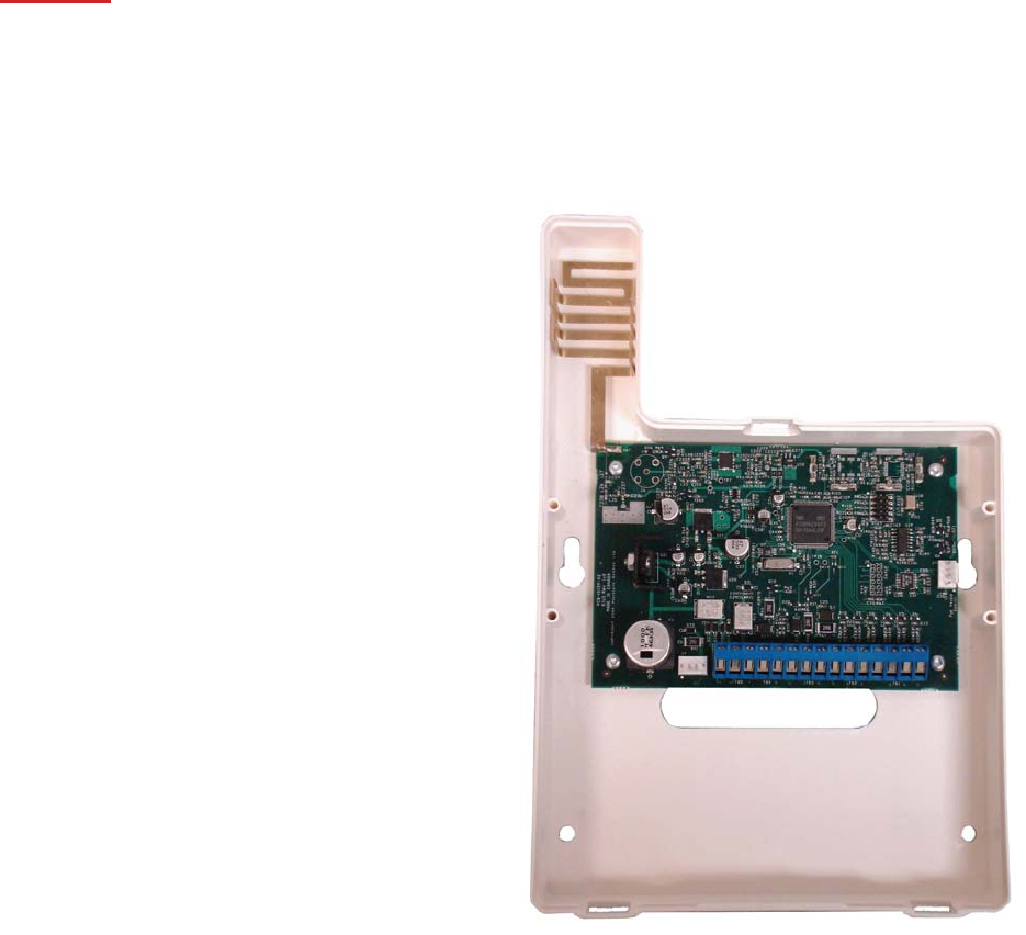
Figure #1
22
You can double the maximum wire length if you double the conductors and connect them in parallel. Mount the TLR
as close to the power supply as possible.
TRBL Trouble Terminals
OUT TRBL Output Terminal
The OUT TRBL output terminal will switch to ground when the TLR detects a trouble condition. The OUT TRBL
terminal may be connected to a control panel zone terminal to report Tela-Link™ (TLR) trouble conditions to the security
system, or the OUT TRBL terminal may be used to activate a visual or audible trouble indicator. This output may be
used to activate a trouble indicator, such as an LED indicator, a low current sounder, or relay connected to another
device.
COM Terminal
When using the TLR with a security system, with sufficient power, connect the COM terminal to the negative DC power
supply terminal of the security system control panel.
YEL and GRN Keypad Terminal
The GRN KEYPAD terminal is used to connect the keybus green from the PANEL. The YEL KEYPAD terminal is not
used.
Keybus Connections
Panel Tela-Link
Bell+ Red - 12 +
Keybus Black To AUX-
Keybus Green To GRN
Keybus Yellow To YEL
Note: Do not connect the Keybus RED wire to the Tela-Link™ (TLR).
Programming the telA-link™
Program the Tela-Link™ (TLR) through Installer’s Programming at a system keypad, or downloading
software. For instructions on keypad programming using Installer’s Programming sections, please refer to
section 4 “How to Program” in your control panel Installation Manual.
To enter Installer’s programming:
1. Go to Installer’s Programming by entering [*][8][Installer’s code].
2. For PC5015, PC5010, PC1555 and PC580: Go to the Tela-Link™ (TLR) programming
section by entering [803]. For PC1575: Go to the Tela-Link™ (TLR) programming section by
entering [86].
23
Programming Data
Most sections contain groups of 2-digit entries. The keypad will beep twice after each 2-digit group is
entered. When a section is entered, on LED keypads, zone lights 1 through 4 will indicate, in binary format,
the value of the first digit in the section. If you wish to change the digit displayed, enter the new digit. If you
wish to keep that digit unchanged, skip over the digit by pressing the [F] Key. Hexadecimal numbers may
also be entered in most sections. Refer to Hexadecimal Data Programming for instructions. When you are
done programming the section, enter the 2-digit number of the next section to be programmed.
Reviewing Programmed Data
• Enter the 2-digit number of the section to be reviewed.
• LCD keypads will display the current data in the programming section.
• LED keypads will display the first digit of data in the section using zone lights 1 to 4 to represent the ]
value, in binary format. To advance the display to the next digit, press the [F] key.
• At the end of the section, the keypad will beep several times and then return to the Program Mode so
that another section can be selected for review or programming.
hex Data Programming
Certain programming sections may require the entry of data in HEX (hexadecimal, or base 16) format. HEX numbering
uses the numbers 0 through 9 and the letters A through F.
The letters A through F are represented by the number keys 1 through 6. To enter data in HEX format, first press the
[*] key. Press a number key from [1] to [6] to enter a HEX digit then press the [*] key again to return to “decimal”
values.
To enter HEX numbers:
A.......Enter [*][1][*]
B.......Enter [*][2][*]
C.......Enter [*][3][*]
D.......Enter [*][4][*]
E.......Enter [*][5][*]
F.......Enter [*][6][*]
telA-link™ (tlr) Programming Sections
These sections will only be available if a TLR v2.0 (SUI3) is connected to the Keybus.
[86] Tela-Link™ (TLR) Programming Sections for PC1575
24
or
[803] Tela-Link™ (TLR) Programming Section for PC5010, PC5015, PC1555, PC580
[01] TLR Account Code
This 6-digit code is used to identify the system and is transmitted when the TLR initiates communications.
Program a 6-digit code in this section using only numbers from 0 to F.
Note: An account number must be entered in this section before communications through the Tela-Link™
(TLR) can be used. Do not enter Hexadecimal numbers in this section.
[10] maintenance Alarm Reporting Codes
Program 2 digit reporting codes for each of the following reporting codes
• Internal Low Voltage
This code will be sent when the voltage supplied to the Tela-Link™ (TLR) on the 12+ and 12 - terminals is less
then 10.5 VDC for more than 4 minutes
• External AC Trouble
This code will be sent when the AC TRBL input terminal is switched to ground.
• External Low Battery Trouble
This code will be sent when the LB TRBL input terminal is switched to ground.
• Control Panel Connection Trouble
This code will be sent when connection is lost to the panel on the Keybus for more than 60 seconds
• Test Transmission
This code will be sent at the same interval as the test transmission of the panel.
[11] maintenance Restoral Reporting Codes
Program 2 digit reporting codes for each of the following reporting codes
• Internal Low Voltage
This code will be sent when the voltage supplied to the Tela-Link™ (TLR) on the 12+ and 12 - terminals is restored
to more than 11.6 VDC for more than 4 minutes.
• External AC Trouble
This code will be sent when the AC TRBL input terminal is switched to ground.
• External Low Battery Trouble
This code will be sent when the LB TRBL input terminal is switched to ground.
• Control Panel Connection Trouble
This code will be sent when connection is restored to the panel on the Keybus for more then 60 seconds.
25
[20] module Configuration
Module configuration is set using Zone Lights as shown below. After you enter section [20], the options that are “on”
will be shown either by the corresponding zone light being on (LED keypads) or the zone number being displayed
(LCD keypads). Press the corresponding number key to turn an option ON or OFF. When finished, press [#].
Zone Light 1
ON - Communications Enabled - The Tela-Link™ (TLR) will initiate communications for all events that the
panel has reporting codes programmed for.
OFF - Communications Disabled - The Tela-Link™ (TLR) will not initiate communications for events that the
panel has reporting codes programmed for. Disable communications to test the system.
Zone Light 2
OFF - TRBL OUT Normally High Impedance - If there are no trouble conditions detected by the Tela-Link™
(TLR), the TRBL OUT terminal will be high-impedance. The TRBL OUT terminal will switch to ground when
the Tela-Link™ (TLR) detects a trouble condition.
ON - TRBL OUT Normally Low - If there are no trouble conditions detected by the Tela-Link™ (TLR), the TRBL
OUT terminal will be low (ground). The TRBL OUT terminal will switch to high-impedance when the
Tela-Link™ (TLR) detects a trouble condition.
Zone Light 3 to Zone Light 8
INACTIVE ZONES - DSC & Visonic Panel
ACTICE ZONES - Six (6) discrete zones for any panel beside listed above.
26
[30] Call Direction Options
Program which of the following reporting code types the TLR will send to the central station. Press the number
corresponding the appropriate option to turn the reporting type ON or OFF. When finished, press [#].
Option
1 Alarm/restore reporting
2 Tamper/restore reporting
3 Opening/closing reporting
4 System maintenance reporting
5 System test transmission reporting
In most installations, you should program the transmission of alarm/restore reporting codes only. Your radio network,
StarNet Radio Communications™, has limited bandwidth and capacity. The more signals each TLR transmits, the
fewer TLR’s you will be able to install on your network.
NOTE: Sections [81] and [82] apply only to the PC1575 v1.0. All other panels will use the reporting codes
that are programmed for these events in the panel.
[81] miscellaneous Alarm Reporting Codes
Program 2 digit reporting codes for each of the following reporting codes
• General Zone Fault Alarm
This code will be sent when the Tela-Link™ (TLR) receives a General Zone Fault Alarm event from the
PC1575.
• General System Tamper Alarm
This code will be sent when the Tela-Link™ (TLR) receives a General System Tamper Alarm event from the
PC1575.
• General System Supervisory Alarm
This code will be sent when the Tela-Link™ (TLR) receives a General System Supervisory Alarm event from
the PC1575.
[82] miscellaneous Restoral Reporting Codes
Program 2 digit reporting codes for each of the following reporting codes
• General Zone Fault Restoral
27
This code will be sent when the Tela-Link™ (TLR) receives a General Zone Fault Restoral event from the
PC1575.
• General System Tamper Restoral
This code will be sent when the Tela-Link™ (TLR) receives a General System Tamper Restoral event from
the PC1575.
• General System Supervisory Restoral
This code will be sent when the Tela-Link™ (TLR) receives a General System Supervisory Restoral event
from the PC1575.
[83] miscellaneous Alarm Reporting Codes
(PC1555 v2.0 panel only)
Program 2 digit reporting codes for the following (see your PC1555 Installation Manual for more
information):
• Police Code: This code will be sent when the Tela-Link™ (TLR) receives a Police Code event from
the PC1555.
• Delinquency Code: This code will be sent when the Tela-Link™ (TLR) receives a Delinquency event from
the PC1555.
[96] [Installer Code] [96]
Restore Tela-Link™ (TLR) Factory Default Programming for PC1575
[993][Installer Code][993]
Restore Tela-Link™ (TLR) Factory Default Programming for PC5010 v1.1 or later, PC5015, PC1555, PC580
When this section is successfully entered, all programming in the Tela-Link™ (TLR) will be returned to the factory
defaults.
NOTE: This command is unavailable on PC5010 v1.0. If v1.0 is used, a hardware default must be done.
Hardware Reset
On a PC5010 v1.0, a hardware reset must be done. There is no software equivalent for PC5010 v1.0.
1. Remove all power to the Tela-Link™ (TLR)
2. Disconnect all connections made to LB TRBL and TRBL OUT.
3. Use a jumper to short LB TRBL and TRBL OUT terminals.
4. Re-apply power.

28
5. Wait 10 seconds then remove the short.
NOTE: This can also be done if connected to PC1575.
telA-link (tlr) - programming worksheet
[86] Tela-Link™ (TLR) Programming Sections for PC1575 OR [803] Tela-Link™ (TLR) Programming Section for
PC5010, PC5015, PC1555, PC580
[01] RF (Radio Frequency) Identification Code (Unit I.D.)
Default
I______I______I______I______I I______I______I______I______I
Unit I.D. is a 6-digit code
SIU3/Tela-Link#3 = Use All 6 digits
[10] Maintenance Alarm Reporting Codes
I______I______I Internal Low Voltage Trouble
I______I______I External AC Trouble
I______I______I External Low Battery Trouble
I______I______I Control Panel Connection Trouble
I______I______I Test Transmission

29
[11] Maintenance Restoral Reporting Codes
I______I______I Internal Low Voltage Trouble Restore
I______I______I External AC Trouble Restore
I______I______I External Low Battery Trouble Restore
I______I______I Control Panel Connection Trouble Restore
[20] Module Configuration
Default Option Option ON Option OFF
ON I______I 1 Communications enabled Communications disabled
OFF I______I 2 TRBL OUT Normally Low TRBL OUT Normally High Impedance
OFF I______I 3-8 Future Use Future Use
[30]Call Direction Options
Default Option ON OFF
ON I_______I 1 larm/restore reporting enabled Disabled
ON I_______I 2 Tamper/restore reporting enabled Disabled
OFF I_______I 3 Opening/closing reporting enabled Disabled
ON I_______I 4 System maintenance reporting enabled Disabled
ON I_______I 5 System test transmission reporting enabled Disabled
OFF I_______I ON 6-8 Future Use
[81] Miscellaneous Alarm Reporting Codes
I______I______I General Zone Fault Alarm
I______I______I General System Tamper Alarm
I______I______I General System Supervisory Alarm
[82] Miscellaneous Restoral Reporting Codes
I______I______I General Zone Fault Restore
I______I______I General System Tamper Restore
I______I______I General System Supervisory Restore
Note: Sections 81 and 82 will be for 1575 v1.0 only.
[83] Miscellaneous Alarm Reporting Codes (PC1555 v2.0 panel only)
Default = FF
I_______I_______I Police Code
I_______I_______I Delinquency Code
30
[96] [Installer Code] [96]
Restore Tela-Link™ (TLR) Factory Default Programming for PC1575
[993][Installer Code][993]
Restore Tela-Link™ (TLR) Factory Default Programming for PC5010 v1.1 or later, PC5015, PC1555, PC580
HOOK UP FULL REPORTING PANEL

31
limited warranty
Tela-Link™ Communications warrants that for a period of twelve months from the date of purchase, the product shall
be free of defect in materials and workmanship under normal use and that in fulfillment of any breach of such warranty,
Tela-Link™ Communications
shall, at its option, repair or replace the defective equipment upon return of the equipment to its repair depot. This
warranty applies only to defects in parts and workmanship and not to damage incurred in shipping or handling, or
damage due to causes beyond the control of Tela-Link™ Communications such as lightning, excessive voltage,
mechanical shock, water damage, or damage arising out of abuse, alteration or improper application of the equipment.
The foregoing warranty shall apply only to the original buyer, and is and shall be in lieu of any and all other warranties,
whether expressed or implied and of all other obligations or liabilities on the part of Tela-Link™ Communications. This
warranty contains the entire warranty. Tela-Link™ Communications neither assumes, nor authorizes any other person
purporting to act on its behalf to modify or to change this warranty, nor to assume for it any other warranty or liability

32
concerning this product.
In no event shall Tela-Link™ Communications be liable for any direct, indirect or consequential damages, loss of
anticipated profits, loss of time or any other losses incurred by the buyer in connection with the purchase, installation or
operation or failure of this product.
WARNING: Tela-Link™ Communications recommends that the entire system be completely tested on a
regular basis. However, despite frequent testing, and due to, but not limited to, criminal tampering or electrical
disruption, it is possible for this product to fail to perform as expected.
© 2005 Tela-Link™ Communications
StarNet Radio Communications™
3510 - 29th Street N.E., Unit 120
Calgary, Alberta Canada T1Y 7E5
(888) 207-STAR (7827) - Phone
(403) 543-9922 - Fax
www.tela-link.com
Printed in Canada 2006
For the records - telA-link™ communications
Client: _________________________________________________________________________
Address: _________________________________________________________________________
_________________________________________________________________________
_________________________________________________________________________
_________________________________________________________________________
Installer: _________________________________ Installation Date: ____________________________
Installer’s Code: ___________________________ Installer’s Lockout: ON OFF
Control Panel: _____________________________ Software Version: ____________________________

33
Installation Notes:
______________________________________________________________________________________
______________________________________________________________________________________
______________________________________________________________________________________
______________________________________________________________________________________
______________________________________________________________________________________
______________________________________________________________________________________
______________________________________________________________________________________
______________________________________________________________________________________
______________________________________________________________________________________
______________________________________________________________________________________
______________________________________________________________________________________
______________________________________________________________________________________
______________________________________________________________________________________
______________________________________________________________________________________
System Complete:
YES NOT COMPLETE
Note: Please keep record on file for future reference and able to present upon request.