Stellar Industries Telescopic Crane Ec2000 Users Manual
2015-02-02
: Stellar-Industries Stellar-Industries-Telescopic-Crane-Ec2000-Users-Manual-488631 stellar-industries-telescopic-crane-ec2000-users-manual-488631 stellar-industries pdf
Open the PDF directly: View PDF ![]() .
.
Page Count: 22
!$%%"!($$ '#&!$(#%$
)
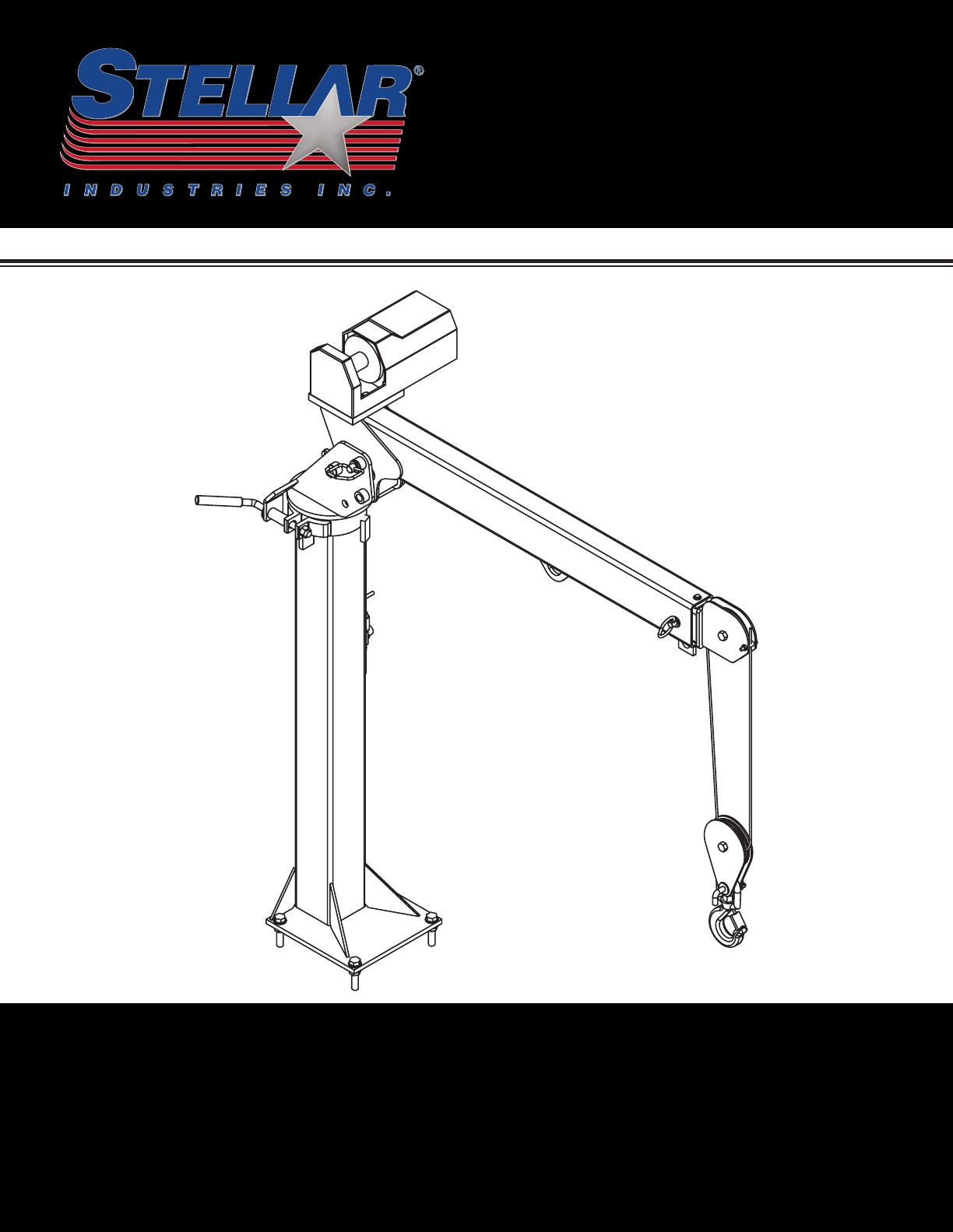
Stellar Industries, Inc.
190 State Street
PO Box 169
Garner, IA 50438
800-321-3741
Fax: 641-923-2811
www.stellarindustries.com Last Revision: 01/23/12
Subject to Change without Notification.
© 2012 Stellar Industries, Inc.

EC2000 Manual Revisions
Date of Revision Description of Revision
Section Revised

Table of Contents
Find a Dealer Near You:
http://www.stellarindustries.com/pages/dist/distsearch.htm
For Technical Questions, Information, Parts, or Warranty, Call Toll-Free at
800-321-3741
Hours: Monday - Friday, 8:00 a.m. - 5:00 p.m. CST
Or email at the following addresses:
Technical Questions, and Information service@stellarindustries.com
Order Parts parts@stellarindustries.com
Warranty Information warranty@stellarindustries.com
Table of Contents
Chapter 1 - Specifications . . . . . . . . . . . . . . . . . . . . . . . . . .1
Capacity Chart - Decal PN 18039 . . . . . . . . . . . . . . . . .2
Chapter 2 - Installation . . . . . . . . . . . . . . . . . . . . . . . . . . . . .3
Wiring Schematic - Power Rotation . . . . . . . . . . . . . . . .4
Wiring Schematic - Manual Rotation . . . . . . . . . . . . . . .4
Control Kit Power Rotation - PN 22930 . . . . . . . . . . . . .5
Stability Procedure . . . . . . . . . . . . . . . . . . . . . . . . . . . . . .6
Stability Capacity Chart . . . . . . . . . . . . . . . . . . . . . . . . . .7
Decal Kit - PN 18776 . . . . . . . . . . . . . . . . . . . . . . . . . . . . .8
Decals of Note . . . . . . . . . . . . . . . . . . . . . . . . . . . . . . . . .8
Chapter 3 - Assembly Drawings . . . . . . . . . . . . . . . . . . . . .9
Standard Crane Assembly - PN 17631 . . . . . . . . . . . . . .9
50’ Wire Rope Crane Assembly - PN 33939 . . . . . . . . .10
Short Mast Crane Assembly - PN 19146 . . . . . . . . . . . .11
Power Rotation Crane Assembly - PN 22601 . . . . . . . .12
Power Rotation/Short Mast Crane Assembly -
PN 24906 . . . . . . . . . . . . . . . . . . . . . . . . . . . . . . . . . . .13
LH Mount Crane Assembly - PN 56658 . . . . . . . . . . . . .14
Control Kit Assembly . . . . . . . . . . . . . . . . . . . . . . . . . . . .15
Chapter 4 - Replacement Parts . . . . . . . . . . . . . . . . . . . . .17
EC2000 Owner’s Manual
Specifications
Chapter 1 - Specifications
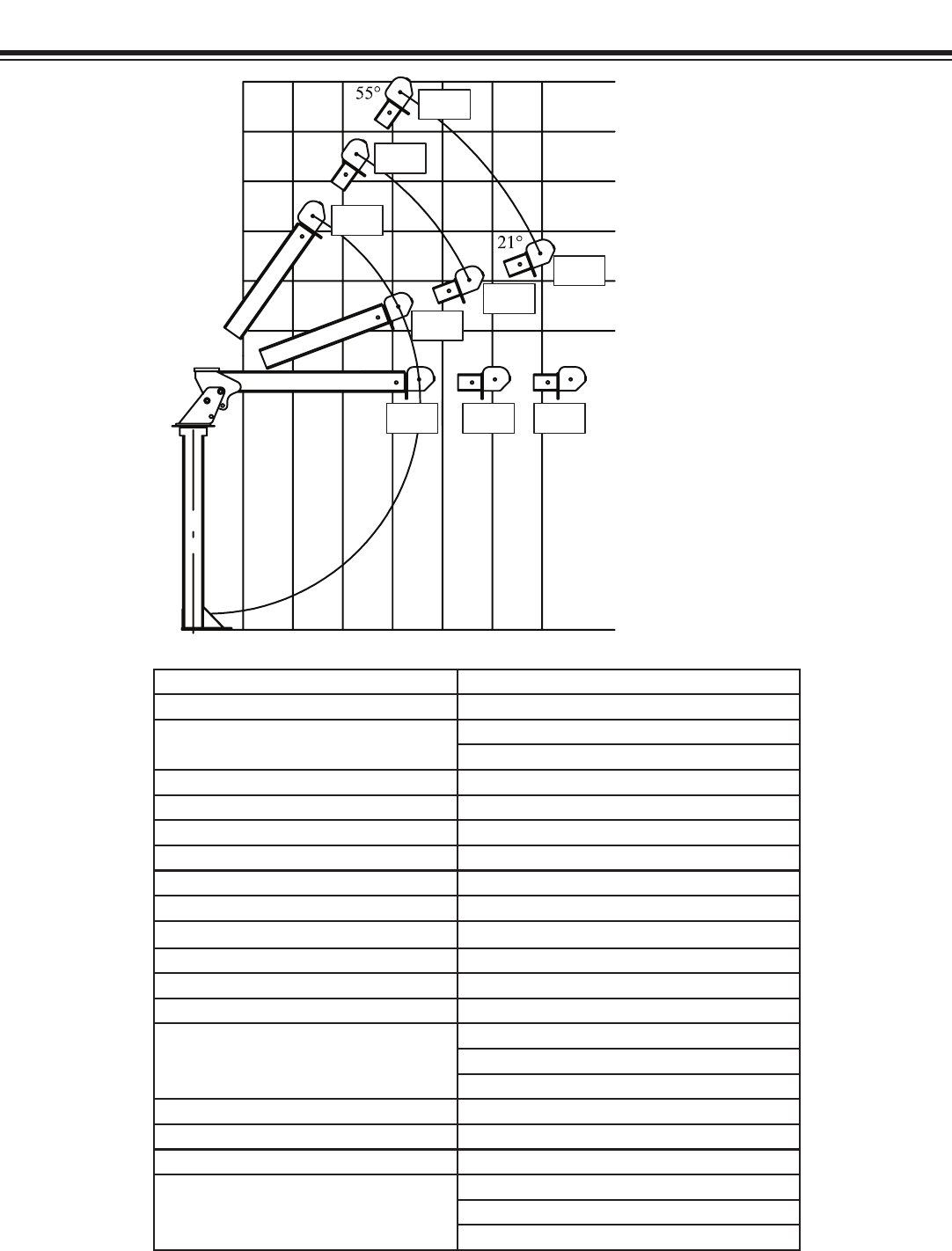
Crane Rating: 6500 ft-lb (.899 TM)
Standard Boom Length: 4’ (1.219 m) from CL of Crane
Boom Extension: 1st Position: Manual 18” (45.7 cm)
2nd Position: Manual 18” (45.7 cm)
Maximum Horizontal Reach: 7’ (2.13 m) from CL of Crane
Maximum Vertical Lift (from crane base): 10’9” (3.28 m)
Boom Elevation: 0 to +21 to +56 degrees
Winch Specification
Rope Diameter: 3/16” (.476 cm)
Line Pull Speed: 20 ft/min (6.10 m)
Max. Single Part Line: 1100 lbs (495 kg)
Max. Double Part Line: 2000 lbs (905 kg)
Manual Rotation: 340˚ Manual
Power Rotation: 314˚ Power
Lifting Capacities: 1580 lbs @ 4’ (715 kg @ 1.219 m)
1190 lbs @ 5’6” (540 kg @ 1.676 m)
930 lbs @ 7’ (420 kg @ 2.13 m)
Stowed Height: 60” (152.4 cm)
Crane Only: 30” (76.2 cm) - Short Mast
Mounting Space Required: 12” x 12” (30.5 cm x 30.5 cm
Approximate Crane Weight: 275 lbs (124.7 kg)
230 lbs (104.3 kg) - Short Mast
300 lbs (136.1 kg) - Power Rotation
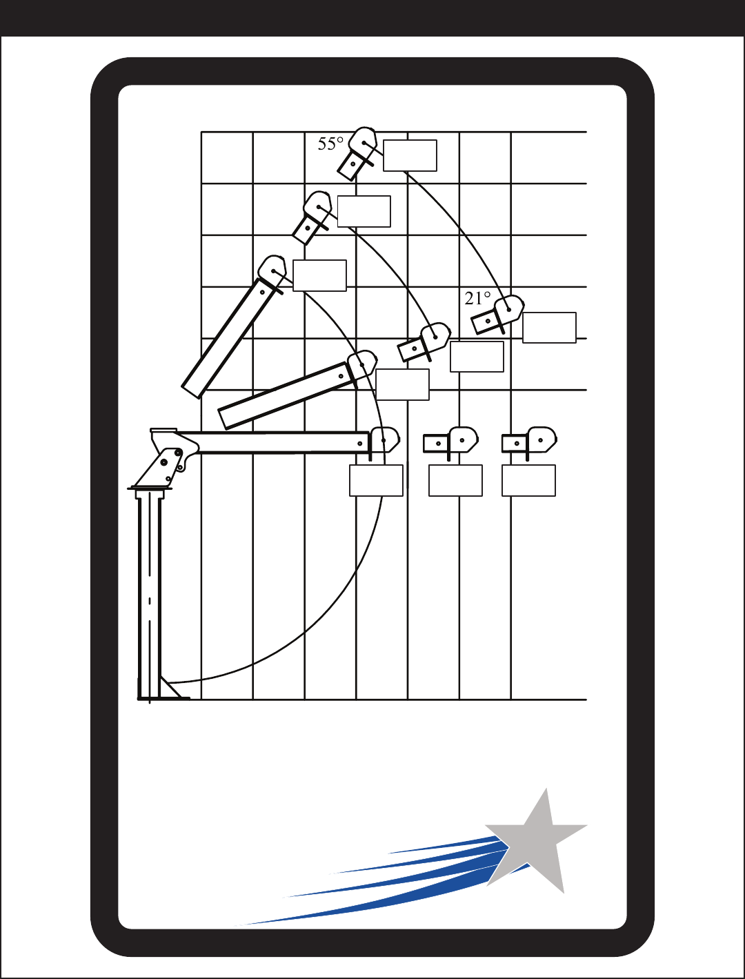
Weight of load handling devices are
part of the load lifted and must be
deducted from the capacity.
Maximum 1 - part line capacity is
1100lbs (495kg). For greater loads,
use 2 - part line.
Reach in Feet/Meters
Capacity in Pounds/Kilograms
1565lbs
710kg
1985lbs
900kg
2000lbs
905kg
1190lbs
540kg
1580lbs
715kg
930lbs
420kg
1430lbs
650kg
1075lbs
490kg
860lbs
390kg
6’
1.83 M
0’
0’
7’
2.13 M
8’
2.44 M
9’
2.74 M
10’
3.05 M
11’
3.35 M
1’
.305 M
2’
.610 M
3’
.914 M
4’
1.22 M
5’
1.52 M
6’
1.83 M
7’
2.13 M
EC2000 Owner’s Manual
Weight of load handling devices are
part of the load lifted and must be
deducted from the capacity.
Maximum 1 - part line capacity is
1100lbs (495kg). For greater loads,
use 2 - part line.
Reach in Feet/Meters
Capacity in Pounds/Kilograms
PN 18039
1565lbs
710kg
1985lbs
900kg
2000lbs
905kg
1190lbs
540kg
1580lbs
715kg
930lbs
420kg
1430lbs
650kg
1075lbs
490kg
860lbs
390kg
6’
1.83 M
0’
0’
7’
2.13 M
8’
2.44 M
9’
2.74 M
10’
3.05 M
11’
3.35 M
1’
.305 M
2’
.610 M
3’
.914 M
4’
1.22 M
5’
1.52 M
6’
1.83 M
7’
2.13 M
ECEC20002000
Capacity Chart - Decal PN 18039
Installation
Chapter 2 - Installation
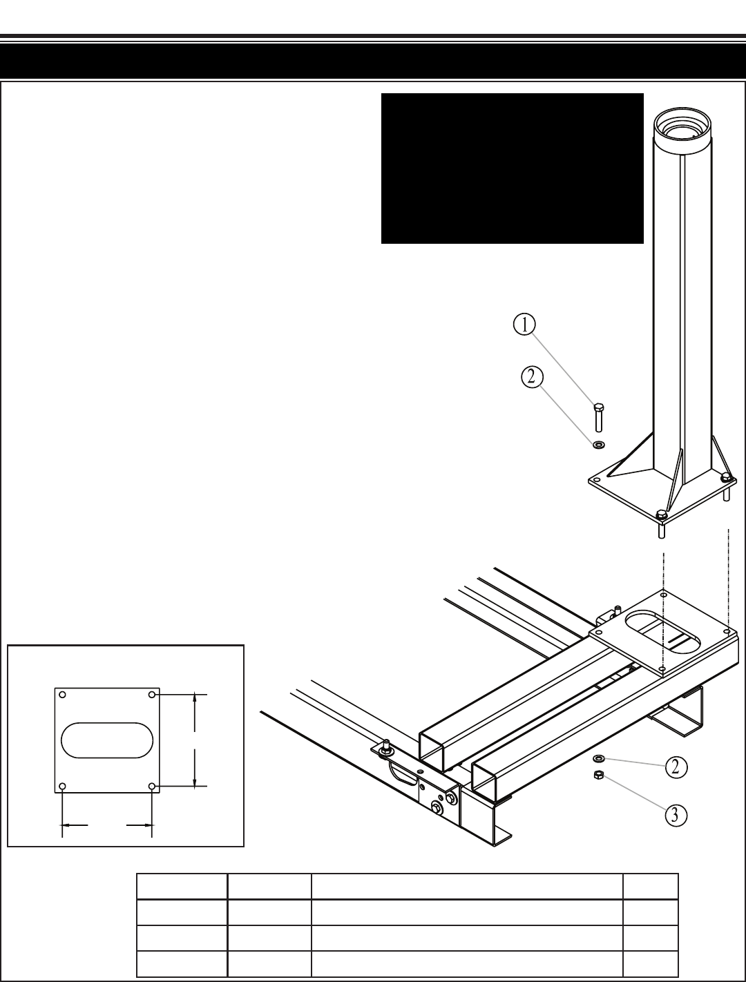
Mounting Hole Diagram
Item No. Part No. Description Qty.
1 D1034 CAP SCR 0.63-11 X 3.00 HHGR8 ZY 4
2 C5902 WASHER 0.63 FLAT GR8 8
3 2826 NUT 0.63-11 HH NYLOC 4
10.25
10.25
Notice: Read this Page Before Installation of the Crane
Installation Instructions:
Prepare Platform For Crane Installation (Not
Supplied)
1. When designing the platform, maintain a
proper clearance for the crane mount-
ing and operation.
2. The platform must be strong enough to
support the crane and rated load.
3. Platform/crane support minimum require-
ments: Top plate should be made from
0.50” grade 50 plate. The structure
should be supported by 4 x 4 x 3/16 tub-
ing.
Mounting Instructions:
1. Lower the crane onto the mounting plat-
form.
2. Mount the crane using 5/8” grade 8
bolts, flat washers, and nyloc nuts.
3. Connect power (+12V) and ground wires
per winch manufacturer’s specifications.
Power Rotation: Route 4 ga. wires (not
included) from junction box to power
(+12V) and ground. Recommended:
Use solenoid and a toggle switch to
power the crane.
4. Operate the crane for several cycles.
Important: When installing welder units to
the service bodies, it is highly
recommended that a surge protector is
installed on the chassis batteries to protect
the crane radio receiver, wiring and other
electronic devices from an unexpected
electrical spike or surge. Failure to do so
could result in extensive damage to the
service body and crane electrical circuit.
EC2000 Owner’s Manual
E-Brake
Ground
Ground Stud
Ec2k M ast
WinchMotor-
Winch M otor+
Battery-
Battery+
Ignition
Switch
Ignition
E-Brake
Ground
Battery -
Battery +
Ground Stud
EC2K Mast
Winch Motor -
Winch Motor +
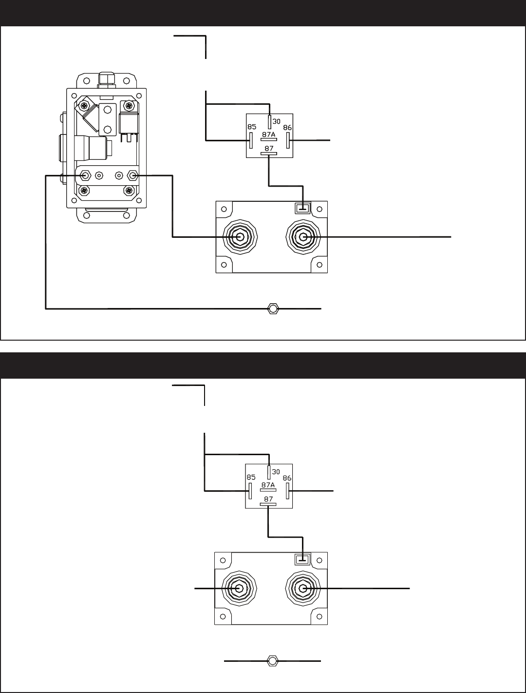
Solid State Solonoid PN 39687
Relay PN C6072
On/Off
Switch
(PN C4815)
Wiring Schematic - Manual Rotation
E-Brake
Ground
Ground Stud
Ec2k Mast
Battery-
Battery
Ignition
Switch
Control Box
Ignition
On/Off
Switch
(PN C4815)
E-Brake
Ground
Ground Stud
EC2K Mast
Battery +
Battery -
Solid State Solonoid PN 39687
Relay PN C6072
Wiring Schematic - Power Rotation
Installation
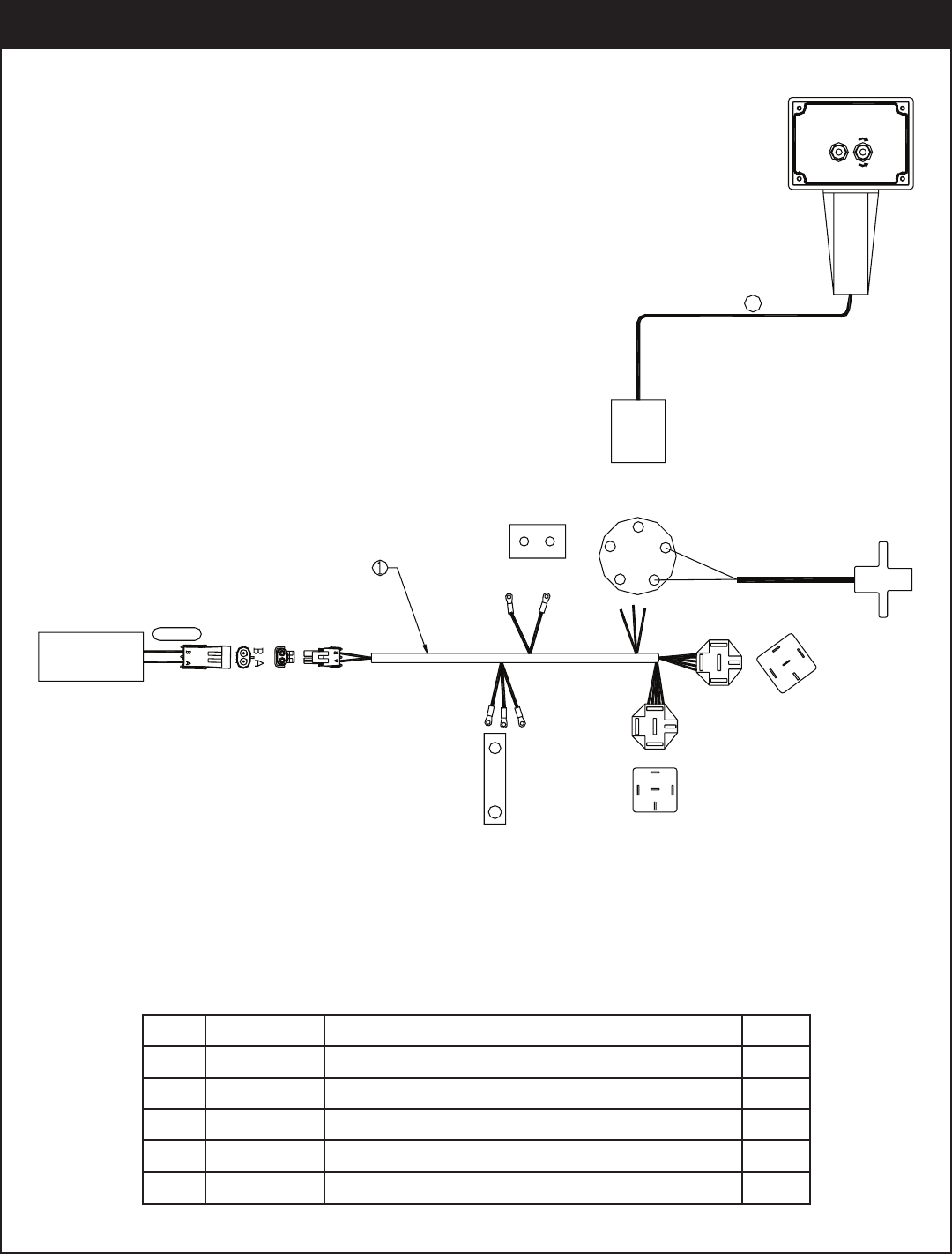
3,4,5
RO TATION
MOTOR
BLACK
RED
CUT W INCH CABLETO
6.5',W ITH 6"OF W IRE
INSIDEOFBOX
2
GROUND
PO W ER RO TATION
CW
RELAY
FRONT
VIEW
PO W ER
RO TATION
AUX
BREAKER
PO W ER
12V
BAT
GD
RT
LT
SA
TM
BLK
GRN
RO TATION
CCW
RELAY
WINCH
DOWN
UP
Rotation
ITEM PART NO. DESCRIPTION QTY
01 28834 WIRE HARNESS 1
02 22932 HANDLE ASM 2 FCTN EC2K POWER 1
03 9751 CONNECT 2 PIN SHROUD PACKARD 1
04 11359 CABLE SEAL 14-16 PACKARD 39001 2
05 13564 CONTACT M TERM SHROUD 12 32038 2
Rotation
Motor
Black
Red
3,4,5
Ground
Power
Breaker
Power
12V
Power
Rotation
Black
Green
Front
View
Bat
Aux GD
TM LT
SA RT
Cut winch cable to
6.5’ with 6” of wire
inside of box.
Rotation
CCW
Relay
Rotation
CW
Relay
PN 22930
Control Kit Power Rotation - PN 22930
EC2000 Owner’s Manual
Definition of Stability for the Stellar Telescopic Crane Products:
A truck is stable until the load cannot be lifted off the ground with the winch, without
tipping over the truck. Every Stellar crane installed must be tested for stability to
determine the actual load capacity of the final truck package. The actual test data
must be recorded and supplied with the truck at the time of in-service and should be kept
with the truck at all times. The following procedure will test the truck package for stability
and will provide a stability capacity chart. The load limit information shown on the
stability capacity chart is formulated on 85% tipping.
Set Up:
1. Locate the truck on a test course in position for loading and engage travel brakes.
2. Set stabilizers so that they make contact with firm, level footings.
3. Operate the crane under partial load to assure operator proficiency and proper
machine function.
Test Procedure
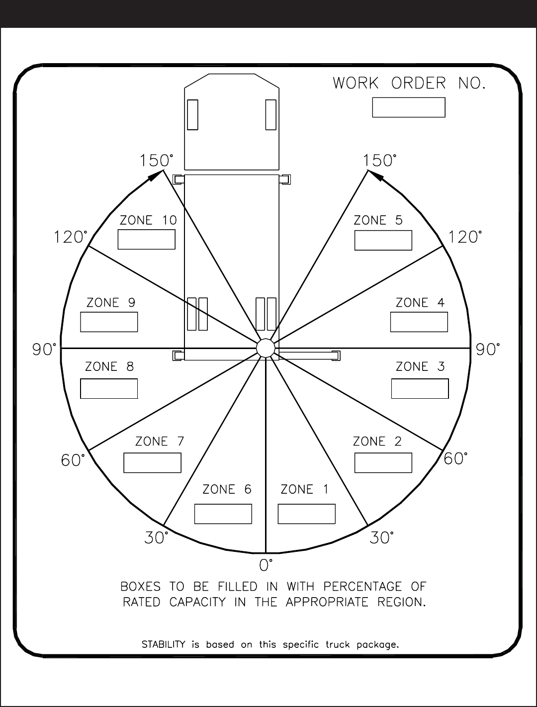
1. Rotate the crane into Zone 1 position.
2. With the crane fully retracted and the boom horizontal, winch the test weight off the
ground. Note: Keep weight within six inches of the ground at all times.
3. Extend the boom outward until full extension has been reached or until the truck
becomes unstable (Again, use the winch to keep the weight within six inches of the
ground.)
4. If the boom goes full extension without becoming unstable, the crane is termed stable
for this zone and 100% can be written in the Zone 1 data box.
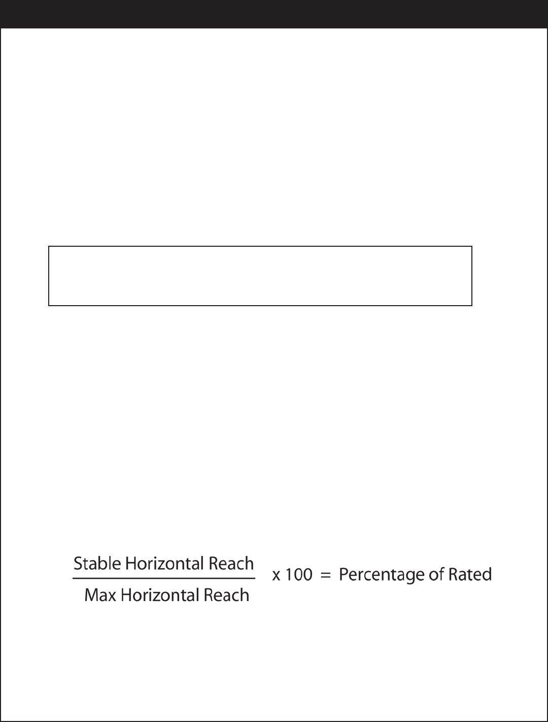
5. If the truck becomes unstable prior to going full extension, retract the boom until the
truck becomes stable and measure the horizontal reach in this position (center of
rotation to boom tip). This is the stable horizontal reach for this zone. Stable horizontal
reach divided by Maximum horizontal reach multiplied by 100 equals the percentage
of rated capacity for this zone. Use the following formula to determine the percentage
of rated capacity:
6. Record this number in the data box for Zone 1. This is the revised capacity due to
stability for this zone.
7. Repeat this procedure for each zone until the worksheet is completed.
8. This is the revised capacity based on stability of this package.
EC2000 Stability Data
Max Horizontal Reach: 180” (From the center of rotation to boom tip)
Stability Test Weight: 875 lbs.
Stability Procedure
Installation
STABILITY CAPACITY CHART
Stability Capacity Chart
EC2000 Owner’s Manual
Item Part No. Description QTY
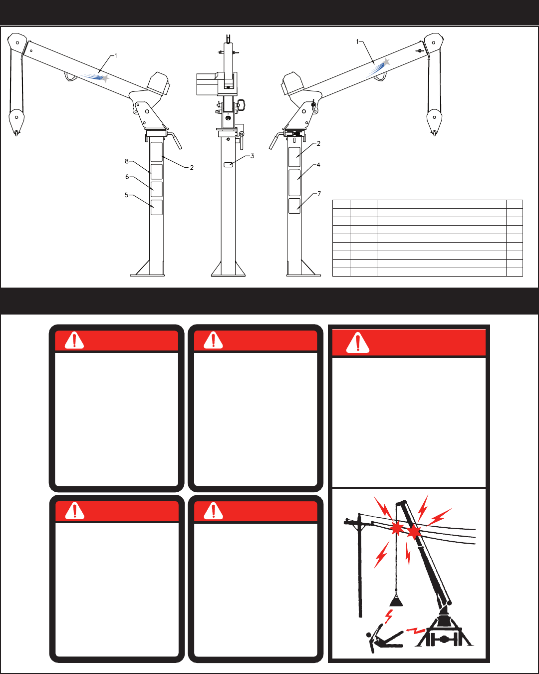
01 18040 DECAL IDENTIFICATION EC2K 2
02 18039 DECAL CAPACITY EC2K 2
03 4214 DECAL CONTACT STELLAR 1
04 6727 DECAL DANGER ELECTROCUTION VERT 1
05 C4540 DECAL DANGER 1
06 4190 DECAL DANGER OPERATION CONDITION 1
07 4189 DECAL DANGER OPERATION RESTRICTION 1
08 C4544 DECAL CAUTION 1
ECEC20002000
1804018040
ECEC20002000
18040
18040
PN 18776
Decals of Note
DANGER
• Main safe clearances from electrical lines. This crane
does not provide protection from contact with or proximity to
an electrically charged conductor. Allow for boom, electrical
line and load line swaying.
• Maintain a clearance of at least 10 feet between any part of
the crane, load line or load and any electrical line carrying
up to 50,000 volts.
• One foot additional clearance is required for every additional
30,000 volts or less.
ELECTROCUTION HAZARD
THIS CRANE IS NOT INSULATED
DEATH OR SERIOUS INJURY
WILL RESULT FROM CONTACT
OR INADEQUATE CLEARANCE
6727
DANGER
FAILURE TO OBEY THE FOLLOWING
WILL RESULT IN
INSTABILITY OR
STRUCTURAL DAMAGE
• Read, understand and follow the equipment
load and work area charts.
• Do not exceed winch or equipment ratings.
• Do not exceed jib load ratings at reduced
boom lengths.
• Weights of accessories attached to the
boom or loadline must be deducted from
the load chart ratings or be added to the
load weight.
4189
DEATH OR SERIOUS INJURY
DANGER
AN UNTRAINED OPERATOR
SUBJECTS HIMSELF AND
OTHERS TO
YOU MUST NOT OPERATE
THIS EQUIPMENT UNLESS
• You have been trained in the safe
operation of this equipment.
• You read, understand and follow the
safety and operating recommendations
contained in the equipment manufacturer’s
manuals, your employer’s work rules and
applicable government regulations.
C4540
DEATH OR SERIOUS INJURY
DANGER
FAILURE TO OBEY THE FOLLOWING
WILL RESULT IN
• Inspect equipment and its operation daily.
• For equipment stability, use only on solid,
level surface with outriggers properly
extended.
• Equipment must be level.
• Operate all controls slowly and smoothly.
• Never operate the equipment with
personnel under boom or load.
• Keep load underboom tip. Do not side
load boom or drag loads. Avoid free
swinging loads.
• Keep at least 3 wraps of loadline on
winch drum.
• For travel, boom and outriggers must be
in stowed position.
C4544
DEATH OR SERIOUS INJURY
DANGER
FAILURE TO OBEY THE FOLLOWING
WILL RESULT IN
• Follow all recommended inspections and
maintenance practices listed in the equipment
manufacturer’s manuals. If manuals are
missing from this equipment, contact
manufacturer for replacement.
• Do not modify or alter this equipment without
written manufacturers approval. Use only
manufacturer approved attachments or parts
on this equiupment.
• Equipment must be mounted on factory
recommended chassis. If re-mounted or
rebuilt, the equipment must be re-certified.
4190
DEATH OR SERIOUS INJURY
Decal Kit - PN 18776
#40365 ON BACK SIDE
1
26
27
5
7
6
8
12
9
10
2
18
17
25
24
23
2221
11
16
15
28
15
13
14
19
16
20
3
4
30
31
22 32
33
43
34
15
35
Ship Loose
36
37
38
29
39
41
Mounting Hardware
42
40
USE COMPOUND
11
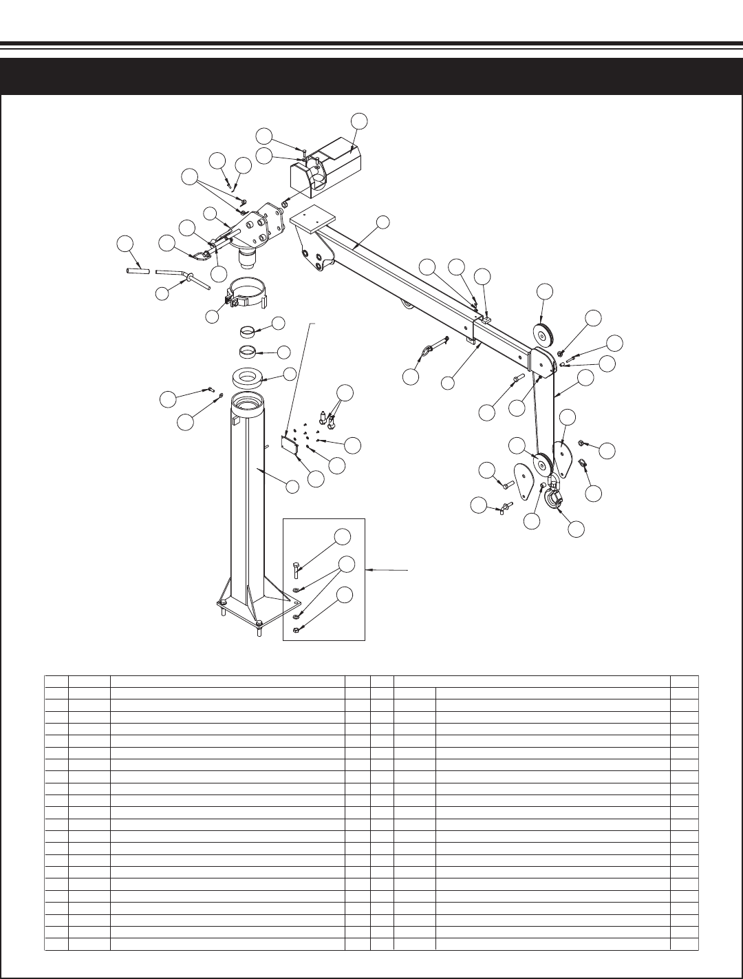
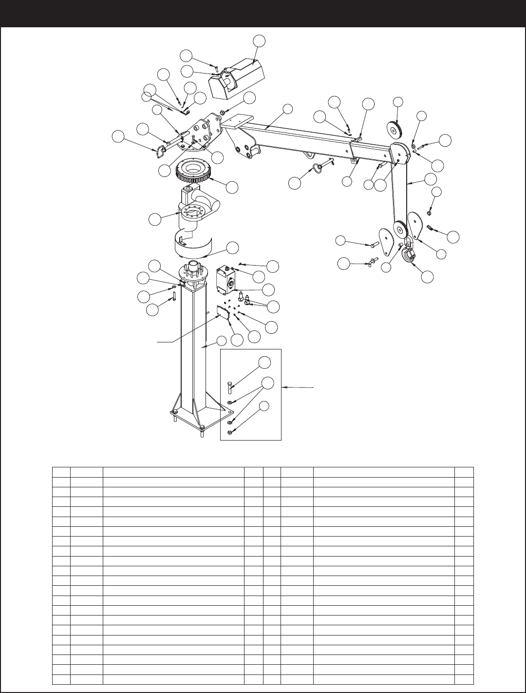
.YTQNOITPIRCSEDTRAPMETI
1K2CE ESAB396931
1K2CE TSAMCP006712
1K2CE MOOB NIAM196933
1K2CE MOOB TXE096934
5 18069 BEARING RADIAL BALL 6" BRB6217-2RS 1
16104-RIROT "05.2 RENNI ECAR860816
7 18067 BEARING DRAWN CUP NEEDLE 2.75" TORB-44161
8 18475PCBR 1K2CE TNEMDLEW EKA
1K2CE TNEMDLEW ELDNAHCP384819
1K2CE PIRG ELDNAH5848101
11 17222 SHEAVE EC2K 5.00 DIA .19R/.75 THK2
183.2X04HCS 57.0 EPIPCP1178121
2KCOLB HCTANS K2CE ETALPCP5697131
14 18036PC1K2CE KCOLB HCTANS RECAPS
6COLYN HH 11-36.0 TUN628251
25RGHH 00.2X11-36.0 RCS PAC993061
1COLYN 8RGHH 01-57.0 TUN8350C71
18 18712 CAP SCR 0.75-10X7.50 HHGR8 ZY1
1GNIHCTAL TNEMDLEW NIPCP4178191
1K2CE TXE POTSCP5178102
2TALF 52.0 REHSAW043012
25RGHH 57.0X02-52.0 RCS PAC974022
.YTQNOITPIRCSEDTRAPMETI
120030 0001 HCNIW4778132
28RG TALF 83.0 REHSAW3536C42
28RGHH 52.1X61-83.0 RCS PAC6753152
1TALF 83.0 REHSAW643062
15RGHH 00.1X61-83.0 RCS PAC153072
1TF04 CAG 91X7 61/3 EPOR ERIW3778182
1HCNYL 65.1X91.0 NIP357592
30 18778 PIN HITCH 0.75X6.25 W\ LANYARD1
31 18777 PIN HITCH 0.63X4.00 W\ LANYARD1
1KCOL 52.0 REHSAW125023
1NOT 3-ENARC KOOH8106C33
34 D1034 CAP SCR 0.63-11 X 3.00 HHGR8 ZY4
35 C5902 WASHER 0.63 SAE FLAT YELLOW GR8 8
15RGHH 57.1X81-13.0 RCS PAC784063
37 19374PC1K2CE PIT MOOB RECAPS
1COLYN HH 81-13.0 TUN243083
39 39687 SOLENOID SOLID STATE SSC 10-1001
40 37751 BOOT TERML SOLENOID SOLID TB-22-22
4CNIZ TALF EAS #8 REHSAW529014
48-32X0.63 BTNHD SS# WERCS6279224
43 C0078HOSE CLAMP #8 RUBBER COATED2
PN 17631
Standard Crane Assembly - PN 17631
Assembly Drawings
Chapter 3 - Assembly Drawings
EC2000 Owner’s Manual
11
1
26
27
5
7
6
8
12
9
10
2
18
17
25
24
23
22
21
11
16
15
28
15
13
14
19
16
20
3
4
30
31
22
33
21
34
32
35
15
36
Ship Loose
37
38
39
29
40
42
43
41
Mounting Hardware
#40365 ON BACK SIDE
USE COMPOUND
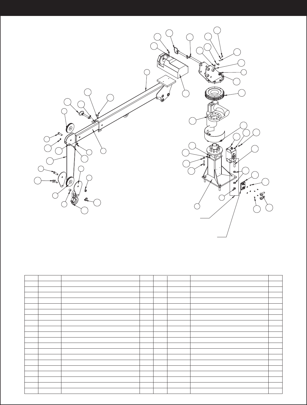
13
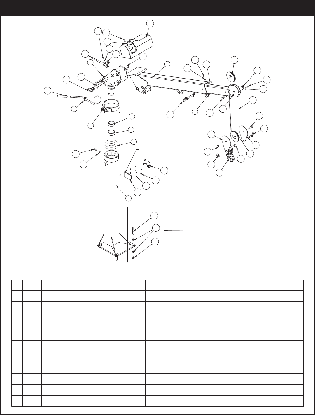
.YTQNOITPIRCSEDTRAPMETI .YTQNOITPIRCSEDTRAPMETI
1K2CE ESAB396931
1K2CE TSAMCP006712
1K2CE MOOB NIAM196933
1K2CE MOOB TXE096934
5 18069 BEARING RADIAL BALL 6" BRB6217-2RS 1
16104-RIROT "05.2 RENNI ECAR860816
7 18067 BEARING DRAWN CUP NEEDLE 2.75" TORB-44161
8 18475PCBR 1K2CE TNEMDLEW EKA
1K2CE TNEMDLEW ELDNAHCP384819
1K2CE PIRG ELDNAH5848101
11 17222 SHEAVE EC2K 5.00 DIA .19R/.75 THK2
183.2X04HCS 57.0 EPIPCP1178121
2KCOLB HCTANS K2CE ETALPCP5697131
14 18036PC1K2CE KCOLB HCTANS RECAPS
6COLYN HH 11-36.0 TUN628251
25RGHH 00.2X11-36.0 RCS PAC993061
1COLYN 8RGHH 01-57.0 TUN8350C71
18 18712 CAP SCR 0.75-10X7.50 HHGR8 ZY1
1GNIHCTAL TNEMDLEW NIPCP4178191
1K2CE TXE POTSCP5178102
2TALF 52.0 REHSAW043012
25RGHH 57.0X02-52.0 RCS PAC974022
120030 0001 HCNIW4778132
28RG TALF 83.0 REHSAW3536C42
28RGHH 52.1X61-83.0 RCS PAC6753152
1TALF 83.0 REHSAW643062
15RGHH 00.1X61-83.0 RCS PAC153072
28 33940 WIRE ROPE 3/16 7X19 IWRC-XIP 50 FT1
1HCNYL 65.1X91.0 NIP357592
30 18778 PIN HITCH 0.75X6.25 W\ LANYARD1
31 18777 PIN HITCH 0.63X4.00 W\ LANYARD1
32 C5946HOSE CLAMP #8 RUBBER COATED2
1KCOL 52.0 REHSAW125033
1NOT 3-ENARC KOOH8106C43
35 D1034 CAP SCR 0.63-11 X 3.00 HHGR8 ZY4
36 C5902 WASHER 0.63 SAE FLAT YELLOW GR8 8
15RGHH 57.1X81-13.0 RCS PAC784073
38 19374PC1K2CE PIT MOOB RECAPS
1COLYN HH 81-13.0 TUN243093
40 39687 SOLENOID SOLID STATE SSC 10-1001
41 37751 BOOT TERML SOLENOID SOLID TB-22-22
4CNIZ TALF EAS 8# REHSAW529024
4#8-32X0.63 BTNHD SS WERCS6279234
PN 33939
50’ Wire Rope Crane Assembly - PN 33939
Assembly Drawings
MOUNTING HARDWARE
38
1
26
27
5
7
6
8
12
9
10
2
18
17
25
24
23
22
21
11
16
15
28
15
29
13
14
19
16
20
3
4
30
31
33
34
42
32
35
41
15
36
SHIP LOOSE
21
39
22
37
40
43
USE COMPOUND
#40365 ON BACK SIDE
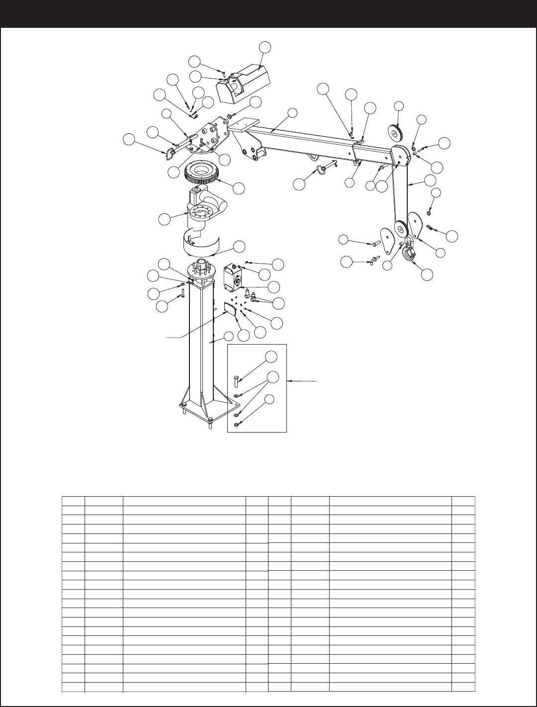
.YTQNOITPIRCSEDTRAPMETI .YTQNOITPIRCSEDTRAPMETI
1TROHS K2CE ESAB307931
1K2CE TSAMCP006712
1K2CE MOOB NIAM196933
1K2CE MOOB TXE096934
5 18069 BEARING RADIAL BALL 6" BRB6217-2RS 1
16104-RIROT "05.2 RENNI ECAR860816
7 18067 BEARING DRAWN CUP NEEDLE 2.75" TORB-44161
8 18475PCBR 1K2CE TNEMDLEW EKA
1K2CE TNEMDLEW ELDNAHCP384819
1K2CE PIRG ELDNAH5848101
11 17222 SHEAVE EC2K 5.00 DIA .19R/.75 THK2
183.2X04HCS 57.0 EPIPCP1178121
2KCOLB HCTANS K2CE ETALPCP5697131
14 18036PC1K2CE KCOLB HCTANS RECAPS
6COLYN HH 11-36.0 TUN628251
25RGHH 00.2X11-36.0 RCS PAC993061
1COLYN HH 01-57.0 TUN828271
18 18712 CAP SCR 0.75-10X7.50 HHGR8 ZY1
1GNIHCTAL TNEMDLEW NIPCP4178191
1K2CE TXE POTSCP5178102
2TALF 52.0 REHSAW043012
25RGHH 57.0X02-52.0 RCS PAC974022
120030 0001 HCNIW4778132
28RG TALF 83.0 REHSAW3536C42
28RGHH 52.1X61-83.0 RCS PAC6753152
1TALF 83.0 REHSAW643062
15RGHH 00.1X61-83.0 RCS PAC153072
1TF04 CAG 91X7 61/3 EPOR ERIW3778182
1HCNYL 65.1X91.0 NIP357592
30 18778 PIN HITCH 0.75X6.25 W\ LANYARD1
31 18777 PIN HITCH 0.63X4.00 W\ LANYARD1
15RGHH 57.1X81-13.0 RCS PAC784023
1COLYN HH 81-13.0 TUN243033
34 19374PC1K2CE PIT MOOB RECAPS
35 D1034 CAP SCR 0.63-11 X 3.00 HHGR8 ZY4
36 C5902 WASHER 0.63 SAE FLAT YELLOW GR8 8
1NOT 3-ENARC KOOH8106C73
38 C5946HOSE CLAMP #8 RUBBER COATED2
1KCOL 52.0 REHSAW125093
40 39687 SOLENOID SOLID STATE SSC 10-1001
41 37751 BOOT TERML SOLENOID SOLID TB-22-22
4#8-32X0.63 BTNHD SS WERCS
5290
24
4CNIZ TALF EAS 8# REHSAW
62792
34
PN 19146
Short Mast Crane Assembly - PN 19146
EC2000 Owner’s Manual
?
38
#40365 ON BACK SIDE 1
31
17
32
14
33
34
17
18
2
11
10
18
17
16
15
14
5
9
8
19
8
20
6
7
12
9
13
3
4
21
22
15
24
14
25
26
27
Ship Loose
28
29
30
35
36
14
33
37
8
40
39
Mounting Hardware
USE COMPOUND
23
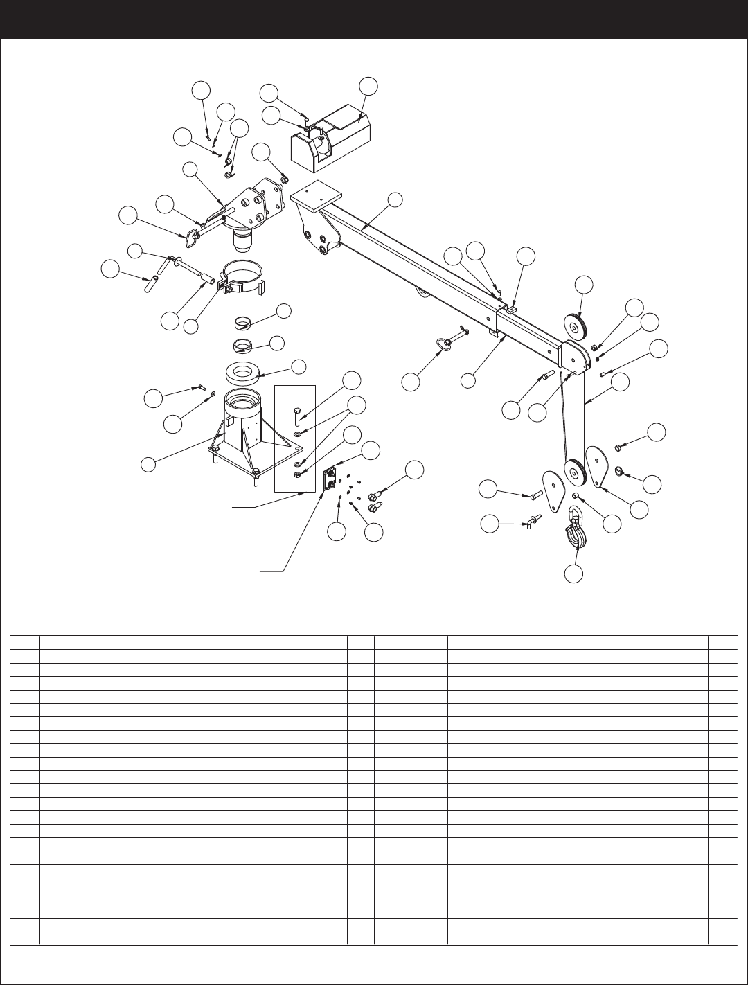
.YTQNOITPIRCSEDTRAPMETI .YTQNOITPIRCSEDTRAPMETI
1REWOP K2CE ESAB886931
222608PCMAST EC2K POWER ROTATION1
1K2CE MOOB NIAM196933
1K2CE MOOB TXE096934
5 17222 SHEAVE EC2K 5.00 DIA .19R/.75 THK 2
6 17965PC PLATE EC2K SNATCH BLOCK 2
7 18036PC SPACER SNATCH BLOCK EC2K 1
8 2826 NUT 0.63-11 HH NYLOC 6
9 0399 CAP SCR 0.63-11X2.00 HHGR5 2
10 C0538 NUT 0.75-10 HHGR8 NYLOC 1
11 18712 CAP SCR 0.75-10X7.50 HHGR8 ZY1
12 18714PC PIN WELDMENT LATCHING 1
1K2CE TXE POTSCP5178131
9TALF 52.0 REHSAW043041
15 0479 CAP SCR 0.25-20X0.75 HHGR52
120030 0001 HCNIW4778161
17 C6353 WASHER 0.38 FLAT GR8 20
18 13576 CAP SCR 0.38-16X1.25 HHGR8 10
19 18773 WIRE ROPE 3/16 7X19 GAC 40FT1
1
4
4
HCNYL 65.1X91.0 NIP357502
21 18778 PIN HITCH 0.75X6.25 W\ LANYARD1
22 18777 PIN HITCH 0.63X4.00 W\ LANYARD1
1LYNIV KLB 05.0 PMALC1800C32
1KCOL 52.0 REHSAW125042
1NOT 3-ENARC KOOH8106C52
26 D1034 CAP SCR 0.63-11 X 3.00 HHGR8 ZY4
27 C5902 WASHER 0.63 SAE FLAT YELLOW GR8 8
28 0487 CAP SCR 0.31-18X1.75 HHGR51
29 19374PC SPACER BOOM TIP EC2K1
30 0342NUT 0.31-18 HH NYLOC1
31 22924 CAP SCR 0.38-16X2.25 HHGR8 10
1K2CE BTT DRAUGCP6162223
33 0478 CAP SCR 0.25-20X0.50 HHGR57
34 22612 BEARING HOUSING SD14511S1
35 22613 BEARING GEAR SY7B0101N-10-B1
36 22930PCCONTROL KIT EC2K POWER 1
37 39687 SOLENOID SOLID STATE SSC 10-1001
38 37751 BOOT TERML SOLENOID SOLID TB-22-22
39 62792 SCREW #8-32X0.63 BTNHD SS
40 5290 WASHER #8 SAE FLAT ZINC
PN 22601
Power Rotation Crane Assembly - PN 22601
Assembly Drawings
20 1
31
17
32
14
33
22
17
18
2
11
23
18
17
16
15
14
5
9
8
19
8
14
6
7
12
9
13
3
4
21 15
10
24
8
27
25
26
34
Ship Loose
28
29
30
35
36 14 33
37
39
40
38
Mounting Hardware
#40365 ON BACK SIDE
USE COMPOUND
5
.YTQNOITPIRCSEDTRAPMETI .YTQNOITPIRCSEDTRAPMETI
139696PCBASE EC2K POWER SHORT1
2 22608PC MAST EC2K POWER ROTATION1
1K2CE MOOB NIAMCP196933
1K2CE MOOB TXECP096934
5 17222 SHEAVE EC2K 5.00 DIA .19R/.75 THK2
6 17965PC PLATE EC2K SNATCH BLOCK2
7 18036PC SPACER SNATCH BLOCK EC2K1
8 2826 NUT 0.63-11 HH NYLOC 6
9 0399 CAP SCR 0.63-11X2.00 HHGR52
10 C0538 NUT 0.75-10 HHGR8 NYLOC 1
11 18712 CAP SCR 0.75-10X7.50 HHGR8 ZY1
12 18714PC PIN WELDMENT LATCHING1
1K2CE TXE POTSCP5178131
9TALF 52.0 REHSAW043041
15 0479 CAP SCR 0.25-20X0.75 HHGR52
120030 0001 HCNIW4778161
17 C6353WASHER 0.38 FLAT GR820
18 13576 CAP SCR 0.38-16X1.25 HHGR810
19 18773 WIRE ROPE 3/16 7X19 GAC 40FT1
1HCNYL 65.1X91.0 NIP357502
PN 24906
21 18778 PIN HITCH 0.75X6.25 W\ LANYARD1
22 18777 PIN HITCH 0.63X4.00 W\ LANYARD1
23 C0081 CLAMP 0.50 BLK VINYL1
1KCOL 52.0 REHSAW125042
1NOT 3-ENARC KOOH8106C52
26 D1034 CAP SCR 0.63-11 X 3.00 HHGR8 ZY4
27 C5902 WASHER 0.63 SAE FLAT YELLOW GR88
28 0487 CAP SCR 0.31-18X1.75 HHGR51
29 19374PC SPACER BOOM TIP EC2K1
30 0342 NUT 0.31-18 HH NYLOC 1
31 22924 CAP SCR 0.38-16X2.25 HHGR810
1K2CE BTT DRAUGCP6162223
33 0478 CAP SCR 0.25-20X0.50 HHGR57
34 22612 BEARING HOUSING SD14511S1
35 22613 BEARING GEAR SY7B0101N-10-B1
36 22930CONTROL KIT EC2K POWER 1
37 39687SOLENOID SOLID STATE SSC 10-1001
38 37751BOOT TERML SOLENOID SOLID TB-22-22
39 62792 SCREW #8-32X0.63 BTNHD SS
40 5290 WASHER #8 SAE FLAT ZINC 4
4
Power Rotation Short Mast Crane Assembly - PN 24906
EC2000 Owner’s Manual
.YTQNOITPIRCSEDTRAPMETI
1 56659PC BASE EC2K POWER LH MNT1
2 22608PC MAST EC2K POWER ROTATION1
1K2CE MOOB NIAMCP196933
1K2CE MOOB TXECP096934
5 17222 SHEAVE EC2K 5.00 DIA .19R/.75 THK2
6 17965PC PLATE EC2K SNATCH BLOCK2
7 18036PC SPACER SNATCH BLOCK EC2K1
8 2826 NUT 0.63-11 HH NYLOC 6
9 0399 CAP SCR 0.63-11X2.00 HHGR52
10 C0538 NUT 0.75-10 HHGR8 NYLOC 1
11 18712 CAP SCR 0.75-10X7.50 HHGR8 ZY1
12 18714PC PIN WELDMENT LATCHING1
1K2CE TXE POTSCP5178131
9TALF 52.0 REHSAW043041
15 0479 CAP SCR 0.25-20X0.75 HHGR52
120030 0001 HCNIW4778161
17 C6353WASHER 0.38 FLAT GR820
18 13576 CAP SCR 0.38-16X1.25 HHGR810
19 18773 WIRE ROPE 3/16 7X19 GAC 40FT1
20 5753 PIN 0.19X1.56 LYNCH1
.YTQNOITPIRCSEDTRAPMETI
38
2
1
31
17
32
14
33
34
17
18
22
11
#40365 ON BACK SIDE
18
17
16
15
14
5
9
8
19
8
20
6
7
12
9
13
3
4
21
15
10
24
14
25
26
27
Ship Loose
28
29
30
35
36
14
33
37
8
40
39
Mounting Hardware
USE COMPOUND
23
PN 56658
21 18778 PIN HITCH 0.75X6.25 W\ LANYARD1
22 18777 PIN HITCH 0.63X4.00 W\ LANYARD1
23 C0081 CLAMP 0.50 BLK VINYL1
1KCOL 52.0 REHSAW125042
25 C6018 HOOK CRANE-3 TON 1
26 D1034 CAP SCR 0.63-11 X 3.00 HHGR8 ZY4
27 C5902 WASHER 0.63 SAE FLAT YELLOW GR88
28 0487 CAP SCR 0.31-18X1.75 HHGR51
29 19374PC SPACER BOOM TIP EC2K1
30 0342 NUT 0.31-18 HH NYLOC 1
31 22924 CAP SCR 0.38-16X2.25 HHGR810
1K2CE BTT DRAUGCP6162223
33 0478 CAP SCR 0.25-20X0.50 HHGR57
34 22612 BEARING HOUSING SD14511S1
35 22613 BEARING GEAR SY7B0101N-10-B1
36 22930CONTROL KIT EC2K POWER 1
37 39687SOLENOID SOLID STATE SSC 10-1001
38 37751 BOOT TERML SOLENOID SOLID TB-22-22
39 62792 SCREW #8-32X0.63 BTNHD SS 4
40 5290 WASHER #10 SAE FLAT ZINC4
LH Mount Crane Assembly - PN 56658
Assembly Drawings
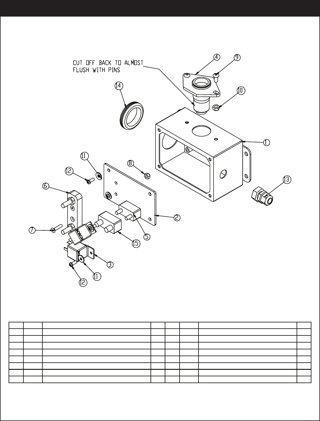
.YTQNOITPIRCSEDTRAPMETI.YTQNOITPIRCSEDTRAPMETI
122925ENCLOSURE 6.00X4.00 MACHINED 1 9 D0561 CAP SCR 0.25-20X0.50 BTNHD SS 2
222927PLATE ELECTRICAL MTG EC2K1100333NUT 0.25-20 HHGR5 NYLOC 2
4CNIZ TALF EAS 01# REHSAW8710D112PMA 03-02 HCSOB YALER2706C3
414994CONNECTOR SOCKET TRAILER 6 PIN 1126684CAP SCR #10-32X0.50 SH 4
522931CIRCUIT BREAKER 12V 20 AMP AUTO RES 1 13 12870 STRAIN RELIEF .38 NPT .08-.24 CABLE 1
623892JUNCTION BLOCK 5/16" 2 POST 1 14 23893 GROMENT RUBBER 1.75 1
7D0896CAP SCR #10-24X0.75 FHSH SS 2 15 23908 BOOT CIRCUIT BREAKER RED 23540 1
2SS COLYN HH 42-01# TUN6594C8
Control Kit Assembly
EC2000 Owner’s Manual

Replacement Parts
Chapter 4 - Replacement Parts
ASSEMBLY COMPONENTS
22612 BEARING HOUSING - ROTATION (POWER ROTATION MODELS)
22613 GEAR BEARING - ROTATION (POWER ROTATION MODELS)
18069 BEARING - RADIAL BALL 6.00”
18068 RACE - INNER 2.50”
18067 BEARING DRAWN CUP NEEDLE 2.75”
17222 SHEAVE 5.00” DIA.
18773 WIRE ROPE 40 FT (STANDARD MODELS)
33940 WIRE ROPE 50 FT
18483PC HANDLE WELDMENT EC2K
18485 HANDLE GRIP EC2K
18715PC STOP - EXTENSION WELDMENT
18777 HITCH PIN 0.63”X 4.00” W / LANYARD
18778 HITCH PIN 0.75”X 6.25” W / LANYARD
18714PC PIN WELDMENT - LATCHING
5753 PIN - LYNCH 0.19”X1.56”
C6018 HOOK 3-TON
10709 SAFETY LATCH FOR 3 TON HOOK
ELECTRICAL COMPONENTS
22932 HANDLE ASM 2 FUNCTION EC2K (POWER ROTATION MODELS)
22620 HANDLE ASM - WINCH FUNCTION ONLY (MANUAL ROTATION)
18774 WINCH
39836 COVER - PLASTIC (WINCH)
39687 SOLENOID - SOLID STATE SSC 10-100
37751 BOOT - SOLID STATE SOLENOID TERMINALS
28834 WIRE HARNESS (POWER ROTATION MODELS)
C6072 BOSCH RELAY (POWER ROTATION MODELS)
22931 CIRCUIT BREAKER (POWER ROTATION MODELS)
23908 BOOT - CIRCUIT BREAKER RED (POWER ROTATION MODELS)
14994 CONNECTOR SOCKET - TRAILER 6 PIN (POWER ROTATION MODELS)
23892 JUNCTION BLOCK 5/16” 2 POST (POWER ROTATION MODELS)

Limited Warranty Statement
Stellar Industries, Inc. (Stellar) warrants products designed and manufactured by Stellar to be free from defects in material and workmanship under
proper use and maintenance. Products must be installed and operated in accordance with Stellar’s written instructions and capacities. This warranty
shall cover the following:
Stellar Cranes, Stellar Hooklift Hoists, Stellar Cable Hoists, Stellar Container Carriers, Stellar Service Trucks, and Stellar X-Tra-Lift Systems:
Twelve (12) month warranty on parts from the date recorded by Stellar as the in-service date, not to extend beyond twenty-four (24) months from date
ofmanufacture,
Twelve (12) month repair labor from the date recorded by Stellar as the in-service date, not to extend beyond twenty-four (24) month from date of
manufacture, and
Thirty-six (36) month warranty on all Stellar Manufactured structural parts from the date recorded by Stellar as the in-service date, not to extend beyond
forty-eight (48) months from date of manufacture.
Stellar Tarper Systems:
Twelve (12) month warranty on parts from the date recorded by Stellar as the in-service date, not to extend beyond twenty-four (24) months from date
of manufacture and
Three (3) month repair labor from the date recorded by Stellar as the in-service date, not to extend beyond fifteen (15) month from date of
manufacture.
The in-service date will be derived from the completed warranty registration card. In the event a warranty registration card is not received by Stellar, the
factory ship date will be used.
Stellar’s obligation under this warranty is limited to, and the sole remedy for any such defect shall be, the repair and/or replacement (at Stellar’s option)
of the unaltered part and/or component in question. Stellar after-sales service personnel must be notified by telephone, fax, or letter of any warranty-
applicable damage within fourteen (14) days of its occurrence. If at all possible, Stellar will ship the replacement part within 24-hours of notification by
the most economical, yet expedient, means possible. Expedited freight delivery will be at the expense of the owner.
Warranty claims must be submitted and shall be processed in accordance with Stellar’s established warranty claim procedure. Stellar after-sales service
personnel must be contacted prior to any warranty claim. A return materials authorization (RMA) account number must be issued to the claiming party
prior to the return of any warranty parts. Parts returned without prior authorization will not be recognized for warranty consideration. All damaged parts
must be returned to Stellar freight prepaid; freight collect returns will be refused. Freight reimbursement of returned parts will be considered as part of
the warranty claim.
Warranty service will be performed by any Stellar new equipment distributor, or by any Stellar-recognized service center authorized to service the type
of product involved, or by the Stellar factory in the event of a direct sale. At the time of requesting warranty service, the owner must present evidence
of date of delivery of the product. The owner shall be obligated to pay for any overtime labor requested of the servicing company by the owner, any
field service call charges, and any towing and/or transportation charges associated with moving the equipment to the designated repair/service
provider.
All obligations of Stellar and its authorized dealers and service providers shall be voided if someone other than an authorized Stellar dealer provides
other than routine maintenance service without prior written approval from Stellar. In the case repair work is performed on a Stellar-manufactured
product, original Stellar parts must be used to keep the warranty in force. The warranty may also be voided if the product is modified or altered in any
way not approved, in writing, by Stellar.
The owner/operator is responsible for furnishing proof of the date of original purchase of the Stellar product in question. Warranty registration is the
ultimate responsibility of the owner and may be accomplished by the completion and return of the Stellar product registration card provided with the
product. If the owner is not sure of registration, he is encouraged to contact Stellar at the address below to confirm registration of the product in
question. This warranty covers only defective material and workmanship. It does not cover depreciation or damage caused by normal wear and tear,
accident, mishap, untrained operators, or improper or unintended use. The owner has the obligation of performing routine care and maintenance
duties as stated in Stellar’s written instructions, recommendations, and specifications. Any damage resulting from owner/operator failure to perform such
duties shall void the coverage of this warranty. The owner will pay the cost of labor and supplies associated with routine maintenance.
The only remedies the owner has in connection with the breach or performance of any warranty on the Stellar product specified are those set above.
In no event will Stellar, the Stellar distributor/dealer, or any company affiliated with Stellar be liable for business interruptions, costs of delay, or for any
special, indirect, incidental, or consequential costs or damages. Such costs may include, but are not limited to, loss of time, loss of revenue, loss of use,
wages, salaries, commissions, lodging, meals, towing, hydraulic fluid, or any other incidental cost.
All products purchased by Stellar from outside vendors shall be covered by the warranty offered by that respective manufacturer only. Stellar does not
participate in, or obligate itself to, any such warranty.
Stellar reserves the right to make changes in design or improvement upon its products without imposing upon itself the same upon its products
theretofore manufactured.
This warranty will apply to all Stellar Cranes, Stellar Hooklift Hoists, Stellar Cable Hoists, Stellar Container Carriers, Stellar Service Trucks, Stellar X-Tra-Lift
Systems, and Stellar Tarper Systems shipped from Stellar’s factory after January 1st, 2010. The warranty is for the use of the original owner only and is not
transferable without prior written permission from Stellar.
THIS WARRANTY IS EXPRESSLY IN LIEU OF ANY OTHER WARRANTIES, EXPRESS OR IMPLIED, INCLUDING ANY WARRANTY OF MERCHANTABILITY OR FITNESS FOR
A PARTICULAR PURPOSE. REMEDIES UNDER THIS WARRANTY ARE LIMITED TO THE PROVISION OF MATERIAL AND SERVICES, AS SPECIFIED HEREIN. STELLAR
INDUSTRIES, INC. IS NOT RESPONSIBLE FOR INCIDENTAL OR CONSEQUENTIAL DAMAGES.
Revision Date: February 2010 Document Number: 37040
EC2000 Owner’s Manual
