Stihl Fs360C Instruction Manual FS 360C Professional Use Brushcutter/Clearing Saw | USA
2014-07-06
: Stihl Fs360C-Instruction-Manual fs360c-instruction-manual stihl pdf
Open the PDF directly: View PDF ![]() .
.
Page Count: 120 [warning: Documents this large are best viewed by clicking the View PDF Link!]
{
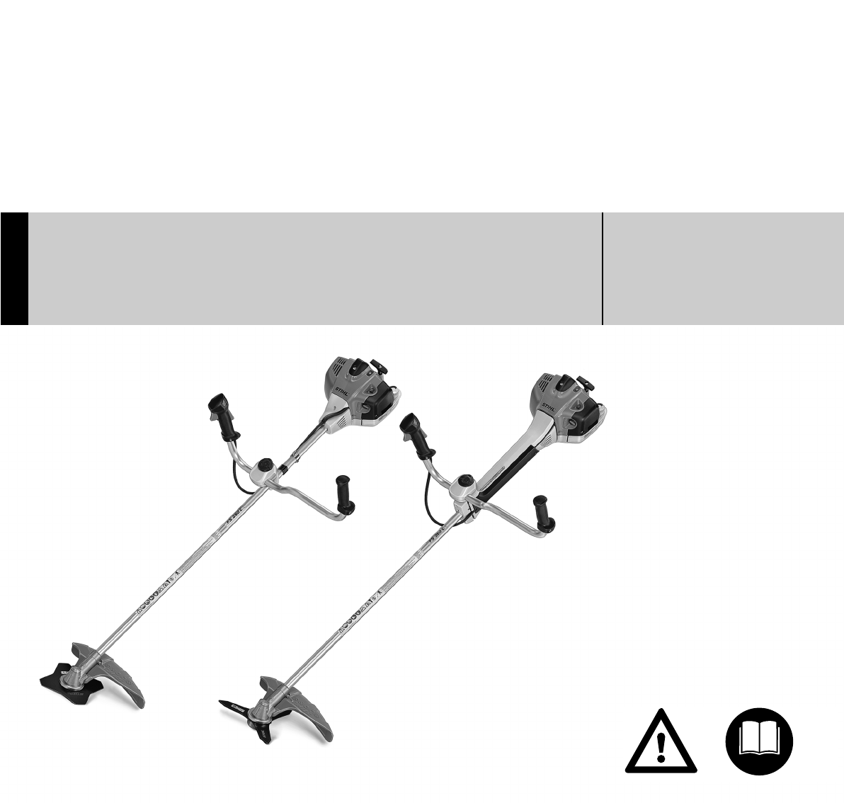
STIHL FS 260 C, 360 C
Warning!
Read and follow all safety precautions in
Instruction Manual – improper use can cause
serious or fatal injury.
Advertencia!
Lea y siga todas las precauciones de
seguridad dadas en el manual de
instrucciones – el uso incorrecto puede
causar lesiones graves o mortales.
Instruction Manual
Manual de instrucciones

Original Instruction ManualPrinted on chlorine-free paper
Printing inks contain vegetable oils, paper can be recycled.
© ANDREAS STIHL AG & Co. KG, 2010
0458-743-8621-A. M0-21.J10.DDS.
0000003973_002_GB
FS 260 C, FS 360 C
English
1
{
Contents
Allow only persons who fully understand
this manual to operate your trimmer /
brushcutter.
To receive maximum performance and
satisfaction from your STIHL trimmer /
brushcutter, it is important that you read,
understand and follow the safety
precautions and the operating and
maintenance instructions in chapter
"Safety Precautions and Working
Techniques" before using your trimmer /
brushcutter. For further information you
can go to www.stihlusa.com.
Contact your STIHL dealer or the STIHL
distributor for your area if you do not
understand any of the instructions in this
manual.
Make sure your unit is equipped with the
proper deflector, handle and harness for
the type of cutting attachment being
used. Always wear proper eye
protection.
Guide to Using this Manual 2
Safety Precautions and Working
Techniques 3
Approved Combinations of Cutting
Attachment, Deflector, Limit Stop
and Harness 16
Mounting the Bike Handle 17
Mounting the Deflector 20
Mounting the Cutting Attachment 21
Fuel 24
Fueling 25
Fitting the Full Harness 26
Balancing the Trimmer/Brushcutter 27
Starting / Stopping the Engine 28
Operating Instructions 30
Cleaning the Air Filter 31
Engine Management 31
Adjusting the Carburetor 32
Winter Operation 32
Spark Plug 33
Engine Running Behavior 35
Replacing the Starter Rope and
Rewind Spring 35
Storing the Machine 37
Sharpening Metal Cutting Blades 38
Inspection and Maintenance by
User 38
Inspections and Maintenance by
Dealer 39
Maintenance and Care 40
Main Parts 42
Specifications 44
Special Accessories 45
Maintenance and Repairs 45
Allocation of STIHL Incorporated
Warranty Declarations 46
STIHL Incorporated Federal
Emission Control Warranty
Statement 46
Allocation of STIHL Incorporated
Warranty Declarations 48
STIHL Incorporated Federal
Emission Control Warranty
Statement 48
STIHL Incorporated California
Exhaust and Evaporative
Emissions Control Warranty
Statement 50
Trademarks 52
Warning!
Because a trimmer / brushcutter is a
high-speed cutting tool some special
safety precautions must be observed to
reduce the risk of personal injury. Care-
less or improper use may cause serious
or even fatal injury.
FS 260 C, FS 360 C
English
2
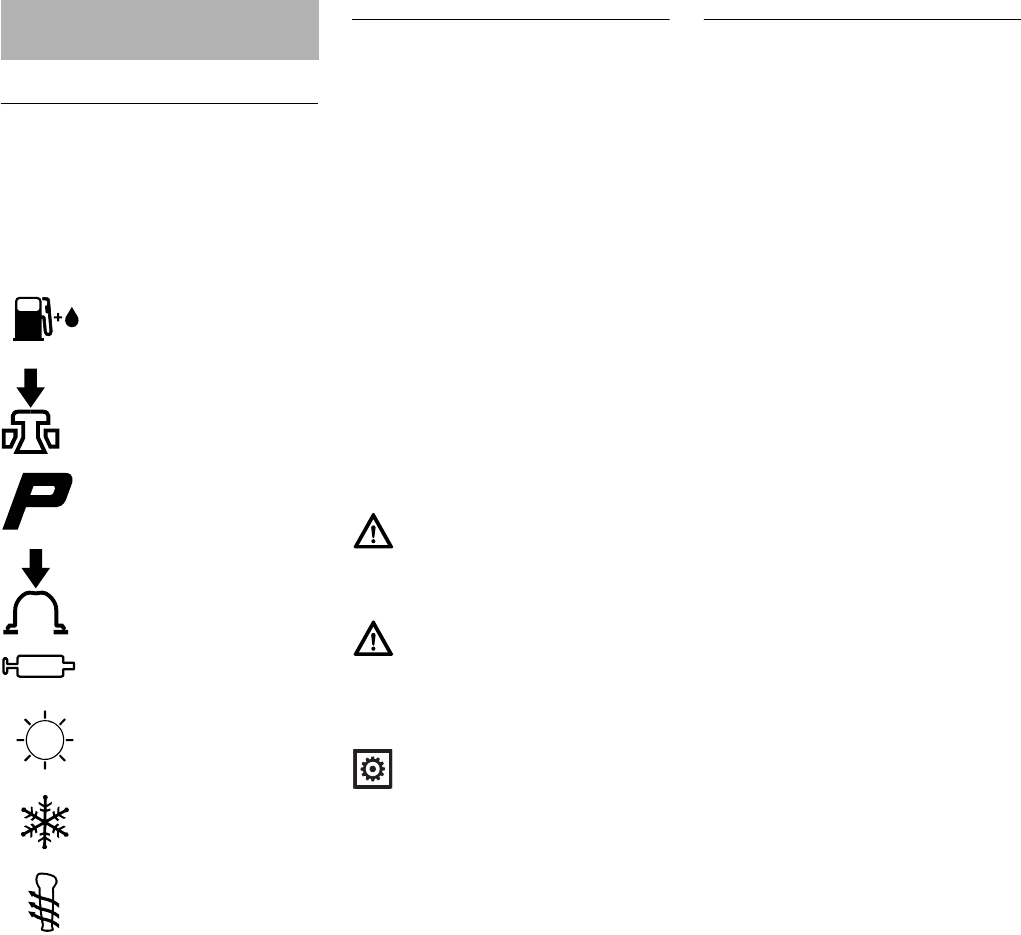
Pictograms
The meanings of the pictograms
attached to or embossed on the
machine are explained in this manual.
Depending on the model concerned, the
following pictograms may be on your
machine.
Symbols in Text
Many operating and safety instructions
are supported by illustrations.
The individual steps or procedures
described in the manual may be marked
in different ways:
NA bullet marks a step or procedure.
A description of a step or procedure that
refers directly to an illustration may
contain item numbers that appear in the
illustration. Example:
NLoosen the screw (1).
NLever (2) ...
In addition to the operating instructions,
this manual may contain paragraphs
that require your special attention. Such
paragraphs are marked with the
symbols and signal words described
below:
Engineering Improvements
STIHL’s philosophy is to continually
improve all of its products. As a result,
engineering changes and improvements
are made from time to time. Therefore,
some changes, modifications and
improvements may not be covered in
this manual. If the operating
characteristics or the appearance of
your machine differs from those
described in this manual, please contact
your STIHL dealer for assistance.
Guide to Using this Manual
Fuel tank for gasoline
and engine oil mixture
Press to operate decom-
pression valve
Manual fuel pump
Press to operate manual
fuel pump
Filler hole for gear
lubricant
Air intake summer mode
Air intake winter mode
Handle heating
Danger!
Indicates an imminent risk of severe or
fatal injury.
Warning!
Indicates a hazardous situation which, if
not avoided, could result in severe or
fatal injury.
Caution!
Indicates a risk of property damage,
including damage to the machine or its
individual components.

FS 260 C, FS 360 C
English
3
The terminology utilized in this manual
when referring to the power tool reflects
the fact that different types of cutting
attachments may be mounted on it. The
term "trimmer" is used to designate an
FS unit that is equipped with a nylon line
head or a head with flexible plastic
blades (i.e., the PolyCut head). A
"brushcutter" designates a unit
equipped with a rigid metal blade. Many
FS models may be used as either a
trimmer or a brushcutter – therefore, the
power tool is referred in this manual as a
"trimmer / brushcutter." Some smaller
and / or lightweight FS models may only
be used as a trimmer, i.e., they may not
be used with metal blades.
The term "clearing saw" indicates a
high-powered trimmer / brushcutter that
is particularly suited for use with a
circular saw blade to clear saplings or
small trees.
Have your STIHL dealer show you how
to operate your power tool. Observe all
applicable local safety regulations,
standards and ordinances.
Use your clearing saw equipped with the
appropriate cutting attachment only for
cutting grass, brush, wood and similar
material.
Safety Precautions and
Working Techniques
Because a clearing saw
is a high-speed, fast-cut-
ting power tool
sometimes equipped with
sharp cutting blades,
special safety precau-
tions must be observed to
reduce the risk of per-
sonal injury.
It is important that you
read, fully understand
and observe the following
safety precautions and
warnings. Read the
instruction manual and
the safety precautions
periodically. Careless or
improper use may cause
serious or fatal injury.
Warning!
As more fully explained later in these
Safety Precautions, to reduce the risk of
personal injury, make sure your unit is
equipped with the proper deflector, limit
stop and harness for the type of cutting
attachment you are using. Use only cut-
ting attachments that are specifically
authorized by STIHL for use on your FS
model.
Warning!
Do not lend or rent your power tool with-
out the instruction manual. Be sure that
anyone using it understands the infor-
mation contained in this manual.
Warning!
The use of this machine may be hazard-
ous. If the rotating line or blade comes in
contact with your body, it will cut you.
When it comes in contact with solid for-
eign objects such as rocks or bits of
metal, it may fling them directly or by ric-
ochet in the direction of bystanders or
the operator. Striking such objects could
damage the cutting attachment and may
cause blades to crack, chip or break.
Thrown objects, including broken heads
or blades, may result in serious or fatal
injury to the operator or bystanders.
STIHL does not recommend the use of
rigid blades when cutting in stony areas.
Warning!
Do not use it for other purposes, since
misuse may result in personal injury or
property damage, including damage to
the machine.
Warning!
Minors should never be allowed to use
this power tool. Bystanders, especially
children, and animals should not be
allowed in the area where it is in use.

FS 260 C, FS 360 C
English
4
Most of these safety precautions and
warnings apply to the use of all STIHL
clearing saws. Different models may
have different parts and controls. See
the appropriate section of your
instruction manual for a description of
the controls and the function of the parts
of your model.
Safe use of a clearing saw involves
1. the operator
2. the power tool
3. the use of the power tool.
THE OPERATOR
Physical Condition
You must be in good physical condition
and mental health and not under the
influence of any substance (drugs,
alcohol, etc.) which might impair vision,
dexterity or judgment. Do not operate
this machine when you are fatigued.
These conditions reduce the hand's
ability to feel and regulate temperature,
produce numbness and burning
sensations and may cause nerve and
circulation damage and tissue necrosis.
All factors which contribute to
whitefinger disease are not known, but
cold weather, smoking and diseases or
physical conditions that affect blood
vessels and blood transport, as well as
high vibration levels and long periods of
exposure to vibration are mentioned as
factors in the development of whitefinger
disease. In order to reduce the risk of
whitefinger disease and carpal tunnel
syndrome, please note the following:
–Most STIHL power tools are
available with an anti-vibration
("AV") system designed to reduce
the transmission of vibrations
created by the machine to the
operator's hands. An AV system is
recommended for those persons
using power tools on a regular or
sustained basis.
–Wear gloves and keep your hands
warm.
–Keep the AV system well
maintained. A power tool with loose
components or with damaged or
worn AV elements will tend to have
higher vibration levels.
–Maintain a firm grip at all times, but
do not squeeze the handles with
constant, excessive pressure. Take
frequent breaks.
All the above-mentioned precautions do
not guarantee that you will not sustain
whitefinger disease or carpal tunnel
syndrome. Therefore, continual and
regular users should closely monitor the
condition of their hands and fingers. If
any of the above symptoms appear,
seek medical advice immediately.
Warning!
To reduce the risk of injury to bystand-
ers and damage to property, never let
your power tool run unattended. When it
is not in use (e.g. during a work break),
shut it off and make sure that unauthor-
ized persons do not use it.
Warning!
Be alert – if you get tired, take a break.
Tiredness may result in loss of control.
Working with any power tool can be
strenuous. If you have any condition
that might be aggravated by strenuous
work, check with your doctor before
operating this machine.
Warning!
Prolonged use of a power tool (or other
machines) exposing the operator to
vibrations may produce whitefinger dis-
ease (Raynaud's phenomenon) or
carpal tunnel syndrome.
Warning!
The ignition system of the STIHL unit
produces an electromagnetic field of a
very low intensity. This field may inter-
fere with some pacemakers. To reduce
the risk of serious or fatal injury, persons
with a pacemaker should consult their
physician and the pacemaker manufac-
turer before operating this tool.
FS 260 C, FS 360 C
English
5
Proper Clothing
To reduce the risk of injury, the operator
should wear proper protective apparel.
Be particularly alert and cautious when
wearing hearing protection because
your ability to hear warnings (shouts,
alarms, etc.) is restricted.
Avoid loose-fitting jackets, scarfs,
neckties, jewelry, flared or cuffed pants,
unconfined long hair or anything that
could become caught on branches,
brush or the moving parts of the unit.
Secure hair so it is above shoulder level.
THE POWER TOOL
For illustrations and definitions of the
power tool parts see the chapter on
"Main Parts."
If this tool is subjected to unusually high
loads for which it was not designed (e.g.
heavy impact or a fall), always check
that it is in good condition before
continuing work. Check in particular that
the fuel system is tight (no leaks) and
that the controls and safety devices are
working properly. Do not continue
operating this machine if it is damaged.
In case of doubt, have it checked by your
STIHL servicing dealer.
THE USE OF THE POWER TOOL
Transporting the Power Tool
Warning!
The deflector provided with your power
tool will not protect the operator from all
foreign objects (gravel, glass, wire, etc.)
thrown back by the rotating cutting
attachment. Thrown objects may also
ricochet and strike the operator.
Warning!
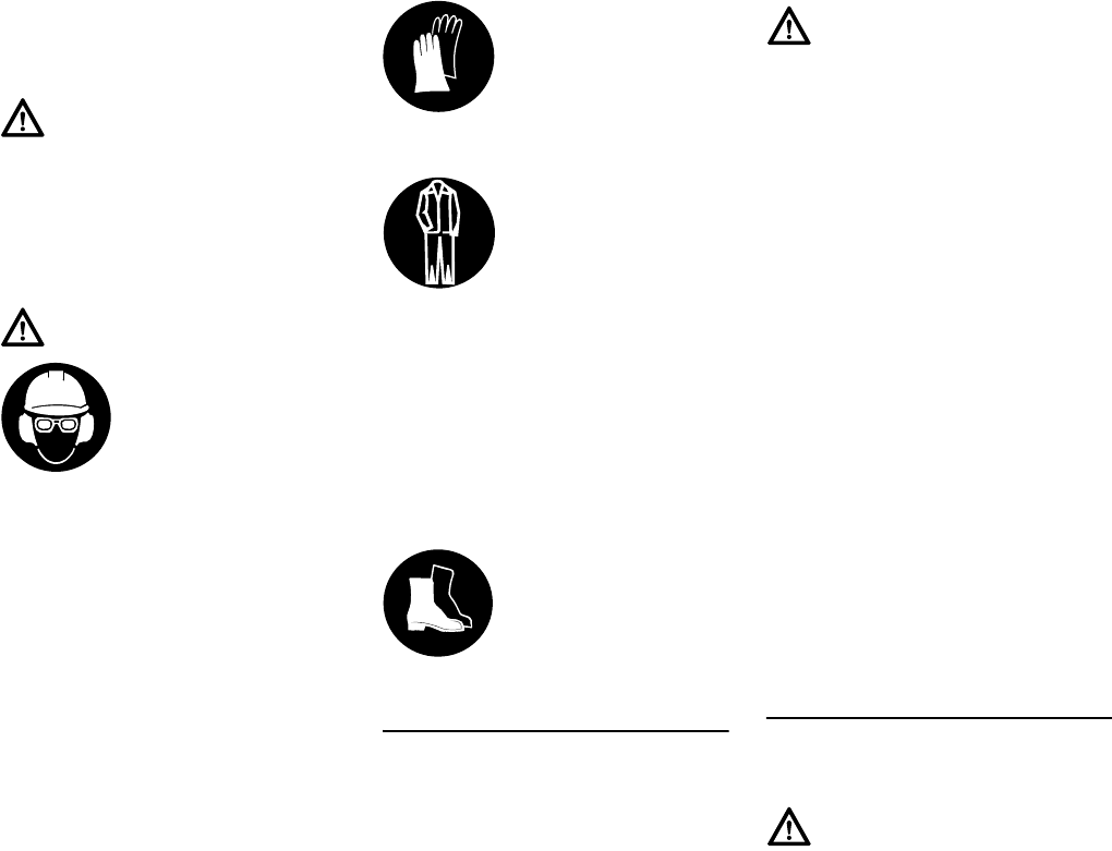
To reduce the risk of
injury to your eyes never
operate your power tool
unless wearing goggles
or properly fitted protec-
tive glasses with
adequate top and side protection com-
plying with ANSI Z 87.1 (or your
applicable national standard). To
reduce the risk of injury to your face
STIHL recommends that you also wear
a face shield or face screen over your
goggles or protective glasses.
Wear an approved safety hard hat to
reduce the risk of injury to your head
when there is a danger of head injuries.
Power tool noise may damage your
hearing. Wear sound barriers (ear plugs
or ear mufflers) to protect your hearing.
Continual and regular users should
have their hearing checked regularly.
Always wear gloves
when handling the
machine and metal
blades. Heavy-duty, non-
slip gloves improve your
grip and help to protect
your hands.
Clothing must be sturdy
and snug-fitting, but allow
complete freedom of
movement. Wear long
pants made of heavy
material to help protect
your legs. Do not wear
shorts, sandals or go
barefoot.
Good footing is very
important. Wear sturdy
boots with nonslip soles.
Steel-toed safety boots
are recommended.
Warning!
Never modify this power tool in any way.
Only attachments supplied by STIHL
and expressly approved by STIHL for
use with the specific STIHL model are
authorized. Although certain unauthor-
ized attachments are useable with
STIHL power tools, their use may, in
fact, be extremely dangerous. For the
cutting attachments authorized by
STIHL for your unit, see the chapter
"Approved Combinations of Cutting
Attachment, Deflector, Limit Stop and
Harness" in the instruction manual or
the STIHL "Cutting Attachments, Parts
& Accessories" catalog.
Warning!
To reduce the risk of injury from loss of
control and blade or line contact, never
carry or transport your power tool with
the cutting attachment moving.
FS 260 C, FS 360 C
English
6
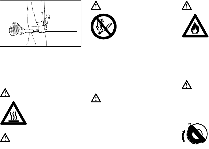
It may be carried only in a horizontal
position. Grip the shaft in a manner that
the machine is balanced horizontally.
Keep the hot muffler away from your
body and the cutting attachment behind
you.
Fuel
Your STIHL power tool uses an oil-
gasoline mixture for fuel (see the
chapter on "Fuel" of your instruction
manual).
Fueling Instructions
In order to reduce the risk of burns and
other personal injury from escaping gas
vapor, remove the fuel filler cap on your
power tool carefully so as to allow any
pressure build-up in the tank to release
slowly. Never remove the fuel filler cap
while the engine is running.
Select bare ground for fueling and move
at least 10 feet (3 m) from the fueling
spot before starting the engine. Wipe off
any spilled fuel before starting your
machine.
Cap with Grip
Warning!
To reduce the risk of
burn injury, do not touch
hot parts of the machine
and the gear housing
when they are hot.
Warning!
Always shut off the engine and make
sure the cutting attachment has stopped
before putting a clearing saw down.
When transporting it in a vehicle, prop-
erly secure it to prevent turnover, fuel
spillage and damage to the unit. STIHL
recommends that you keep metal
blades covered with the transport guard
(optional accessory).
002BA272 KN
Warning!
Gasoline is an extremely
flammable fuel. If spilled
and ignited by a spark or
other ignition source, it
can cause fire and seri-
ous burn injury or
property damage. Use extreme caution
when handling gasoline or fuel mix. Do
not smoke or bring any fire or flame near
the fuel or the power tool. Note that
combustible fuel vapor may escape
from the fuel system.
Warning!
Fuel your power tool in well-ventilated
areas, outdoors. Always shut off the
engine and allow it to cool before refu-
eling. Gasoline vapor pressure may
build up inside the fuel tank depending
on the fuel used, the weather conditions
and the tank venting system.
Warning!
Check for fuel leakage
while refueling and dur-
ing operation. If fuel
leakage is found, do not
start or run the engine
until the leak is fixed and
any spilled fuel has been wiped away.
Take care not to get fuel on your cloth-
ing. If this happens, change your
clothing immediately.
Warning!
In order to reduce the risk of fuel spill-
age and fire from an improperly
tightened fuel cap, correctly position
and tighten the fuel cap in the fuel tank
opening.
To do this with this STIHL
cap, raise the grip on the
top of the cap until it is
upright at a 90° angle.
Insert the cap in the fuel
tank opening with the tri-
angular marks on the grip
of the cap and on the fuel
tank opening lining up.
Using the grip, turn the
cap firmly clockwise as
far as it will go (approx. a
quarter turn).
FS 260 C, FS 360 C
English
7
Before Starting Keep the handles clean and dry at all
times; it is particularly important to keep
them free of moisture, pitch, oil, fuel mix,
grease or resin in order for you to
maintain a firm grip and properly control
your power tool.
As can be seen in that chart, some
cutting attachments may require you to
change your deflector, limit stop and / or
harness.
Keep the deflector (and the attached
skirt where appropriate) adjusted
properly at all times (see chapters on
"Mounting the Deflector" and "Mounting
the Cutting Attachment" of your
instruction manual).
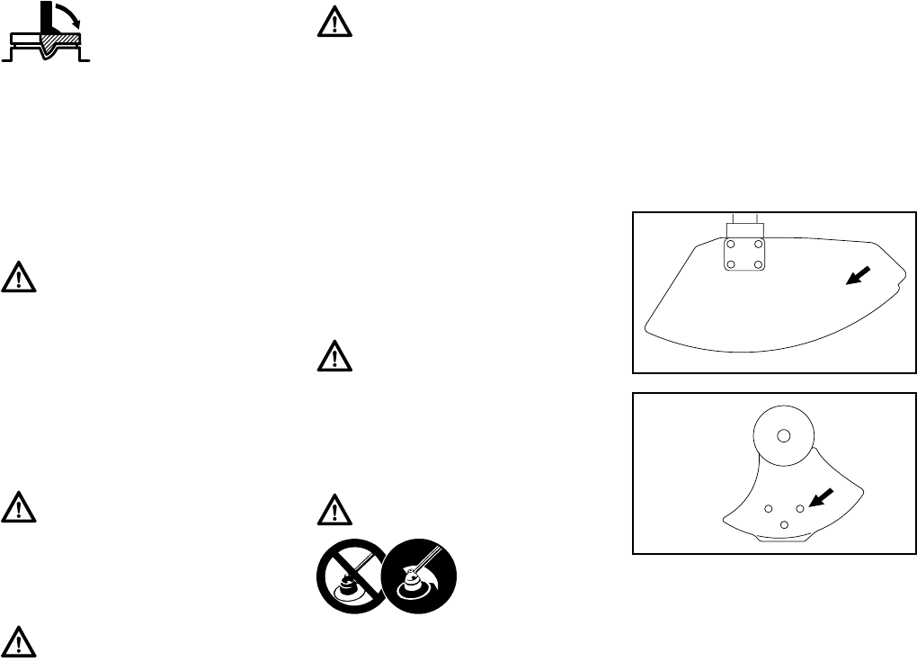
Arrows on the deflector (A) and limit
stop (B) (as seen from the underside)
show the correct direction of rotation of
the cutting attachment. When viewed
from above, however, the cutting
attachment rotates counterclockwise.
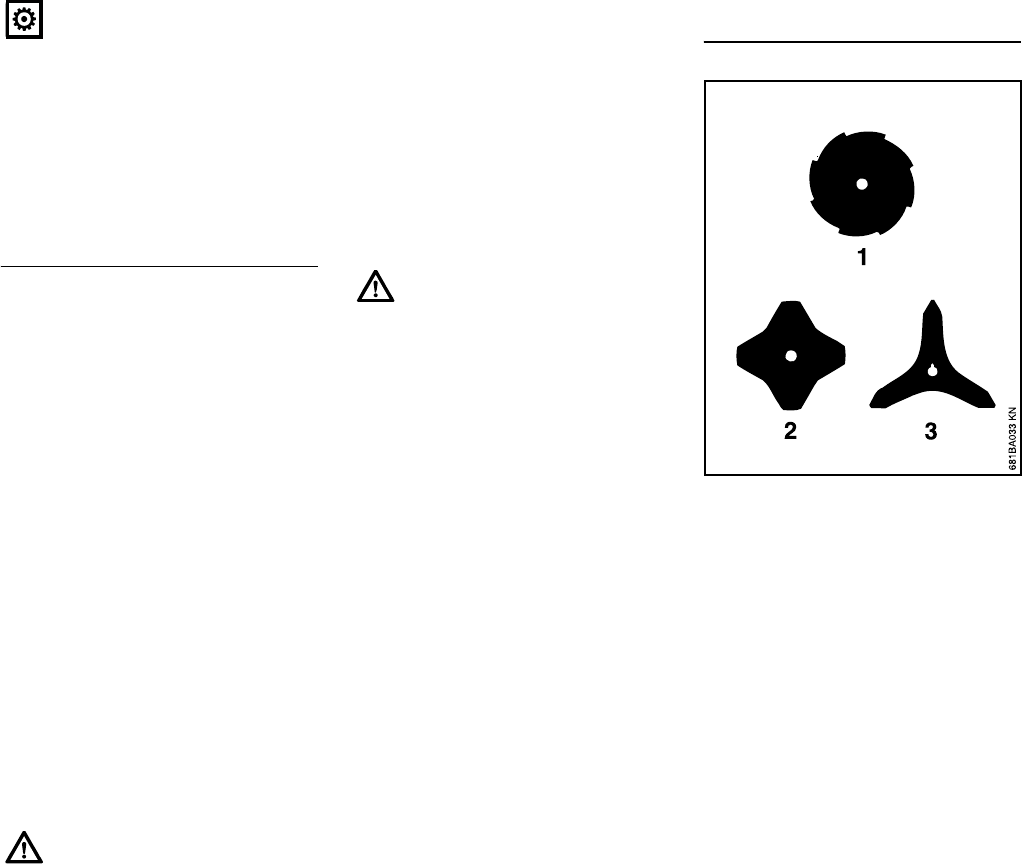
Some of the following symbols may be
embossed on the outside of the deflector
in order to indicate the approved
combination of cutting attachment and
deflector.
Fold the grip flush with
the top of the cap. If the
grip does not lie com-
pletely flush with the cap
and the detent on the grip
does not fit in the corre-
sponding recess in the
filler opening, the cap is
not properly seated and
tightened and you must
repeat the above steps.
Warning!
Always check your power tool for proper
condition and operation before starting,
particularly the throttle trigger, throttle
trigger lockout, momentary stop switch,
cutting attachment, deflector and har-
ness. The throttle trigger must move
freely and always spring back to the idle
position. Never attempt to modify the
controls or safety devices.
Warning!
Never operate your power tool if it is
damaged, improperly adjusted or main-
tained, or not completely or securely
assembled.
Warning!
Do not attach any cutting attachment to
a unit without proper installation of all
required parts. Failure to use the proper
parts may cause the blade or head to fly
off and seriously injure the operator or
bystanders.
Warning!
The cutting attachment must be prop-
erly tightened and in safe operating
condition. Inspect for loose parts (nuts,
screws, etc.) and for cracked or dam-
aged heads or cracked, bent, warped or
damaged blades. Replace damaged
heads or blades before using the power
tool. Always keep blades sharp.
Warning!
Check that the spark plug boot is
securely mounted on the spark plug – a
loose boot may cause arcing that could
ignite combustible fumes and cause a
fire.
Warning!
To reduce the risk
of personal injury
to the operator
from blade or line
contact and
thrown objects, make sure your unit is
equipped with the proper deflector, limit
stop and harness for the type of cutting
attachment being used (see chart in the
chapter on "Approved Combinations of
Cutting Attachment, Deflector, Limit
Stop and Harness").
A
000BA006 KN
B
000BA007 KN
FS 260 C, FS 360 C
English
8
Adjust carrying harness and hand grip to
suit your size before starting work. The
machine should be properly balanced as
specified in your instruction manual for
proper control and less fatigue in
operation. To be better prepared in case
of an emergency, practice releasing the
unit from the harness as quickly as
possible.
Starting
Start the engine at least 10 feet (3 m)
from the fueling spot, outdoors only.
For specific starting instructions, see the
appropriate section of your manual.
Place the power tool on firm ground or
other solid surface in an open area.
Maintain good balance and secure
footing.
Once the engine has started,
immediately blip the throttle trigger,
which should release the starting throttle
and allow the engine to slow down to
idle.
With the engine running only at idle,
attach the power tool to the spring hook
of your harness (see appropriate
chapter of this manual).
Important Adjustments
If you cannot set the correct idle speed,
have your STIHL dealer check your
power tool and make proper
adjustments and repairs.
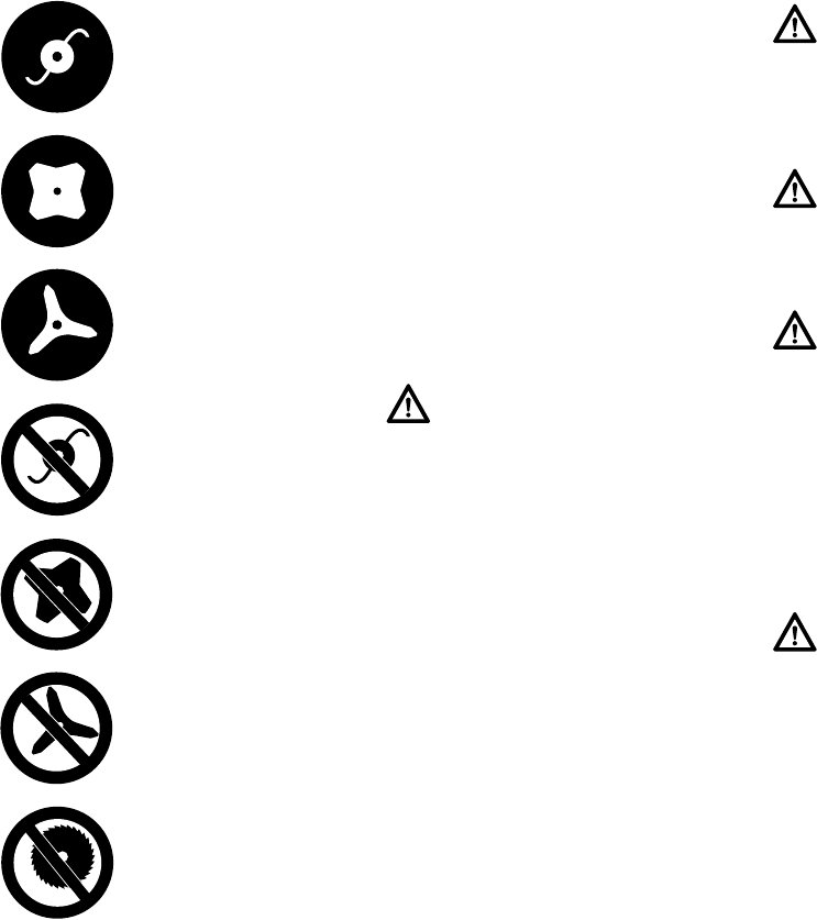
The deflector may be
used in combination with
mowing heads.
The deflector may be
used in combination with
grass cutting blades.
The deflector may be
used in combination with
brush knives.
The deflector must not be
used in combination with
mowing heads.
The deflector must not be
used in combination with
grass cutting blades.
The deflector must not be
used in combination with
brush knives.
The deflector must not be
used in combination with
circular saw blades.
Warning!
To reduce the risk of injury from blade or
line contact, be absolutely sure that the
cutting attachment is clear of you and all
other obstructions and objects, includ-
ing the ground, because when the
engine starts at starting-throttle, engine
speed will be fast enough for the clutch
to engage and move the cutting
attachment.
Warning!
Your power tool is a one-person
machine. Do not allow other persons in
the general work area, even when
starting.
Warning!
To reduce the risk of injury from loss of
control, do not attempt to "drop start"
your power tool.
Warning!
When you pull the starter grip, do not
wrap the starter rope around your hand.
Do not let the grip snap back, but guide
the starter rope to rewind it properly.
Failure to follow this procedure may
result in injury to your hand or fingers
and may damage the starter
mechanism.
Warning!
To reduce the risk of personal injury
from loss of control or contact with the
running cutting attachment, do not use
your unit with incorrect idle adjustment.
At correct idle speed, the cutting attach-
ment should not move. For directions on
how to adjust idle speed, see the appro-
priate section of your instruction
manual.
FS 260 C, FS 360 C
English
9
During Operation
Holding and Controlling the Power
Tool
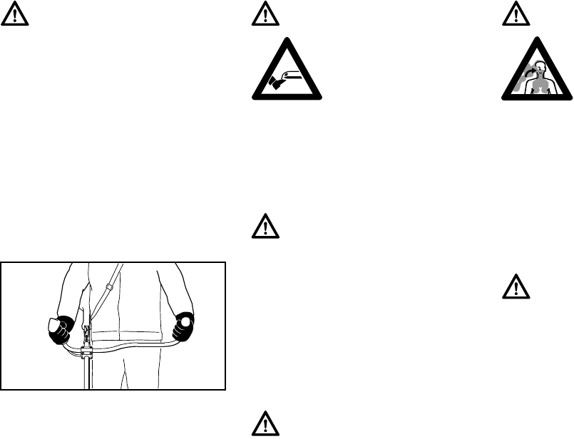
Always hold the unit firmly with both
hands on the handles while you are
working. Wrap your fingers and thumbs
around the handles, keeping the
handles cradled between your thumb
and forefinger.
Working Conditions
Operate and start your power tool only
outdoors in a well-ventilated area.
Operate it under good visibility and
daylight conditions only. Work carefully.
Warning!
This unit is equipped with an ignition
system that is normally in operational
readiness. After the setting lever is used
to stop the engine, it automatically
springs back to the "on" position. If the
engine is warm, it may be possible to
start it by simply pulling the starter rope,
with no further adjustments. To reduce
the risk of injury, be particularly alert to
keep children away from the unit.
002BA257 KN
Warning!
Never attempt to operate
your power tool with one
hand. Loss of control of
the power tool resulting in
serious or fatal injury may
result. To reduce the risk
of cut injuries, keep hands and feet
away from the cutting attachment.
Never touch a moving cutting attach-
ment with your hand or any other part of
your body.
Warning!
Do not overreach. Keep proper footing
and balance at all times. Special care
must be taken in slippery conditions
(wet ground, snow) and in difficult, over-
grown terrain. Watch for hidden
obstacles such as tree stumps, roots
and ditches to avoid stumbling. For bet-
ter footing, clear away scrub and
cuttings. Be extremely cautious when
working on slopes or uneven ground.
Warning!
To reduce the risk of injury from loss of
control, never work on a ladder or on
any other insecure support. Never hold
the cutting attachment above waist
height.
Warning!
As soon as the engine is
running, this product gen-
erates toxic exhaust
fumes containing chemi-
cals, such as unburned
hydrocarbons (including
benzene) and carbon monoxide, that
are known to cause respiratory prob-
lems, cancer, birth defects, or other
reproductive harm. Some of the gases
(e.g. carbon monoxide) may be color-
less and odorless. To reduce the risk of
serious or fatal injury / illness from inhal-
ing toxic fumes, never run the machine
indoors or in poorly ventilated locations.
Warning!
If the vegetation being cut or the sur-
rounding ground is coated with a
chemical substance (such as an active
pesticide or herbicide), read and follow
the instructions and warnings that
accompanied the substance at issue.
FS 260 C, FS 360 C
English
10
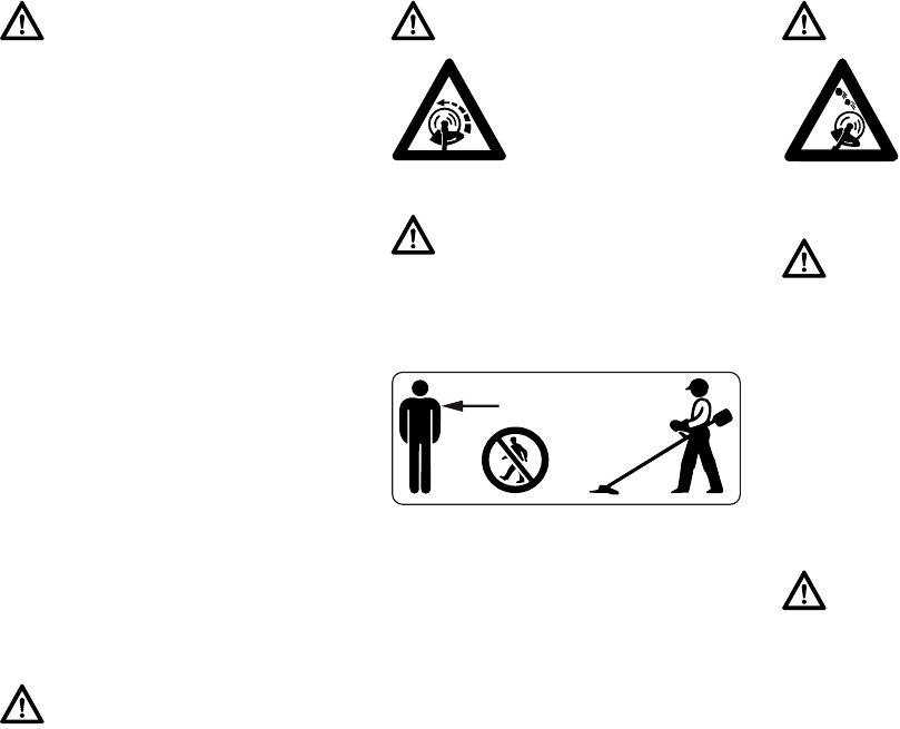
Operating Instructions
In the event of an emergency, shut off
the engine immediately – move the
momentary stop switch to STOP.
To reduce the risk of eye and other injury
always wear proper eye protection (see
the chapter on "Proper Clothing") and
ensure that bystanders are at least
50 feet (15 m) away. To reduce the risk
of damage to property, also maintain this
distance from such objects as vehicles
or windows. Any coworkers who must be
in the restricted area should also wear
goggles or protective glasses. Stop the
engine immediately if you are
approached.
Warning!
Inhalation of certain dusts, especially
organic dusts such as mold or pollen,
can cause susceptible persons to have
an allergic or asthmatic reaction. Sub-
stantial or repeated inhalation of dust
and other airborne contaminants, in par-
ticular those with a smaller particle size,
may cause respiratory or other ill-
nesses. Control dust at the source
where possible. Use good work prac-
tices, such as operating the unit so that
the wind or operating process directs
any dust raised by the power tool away
from the operator. Follow the recom-
mendations of EPA / OSHA / NIOSH
and occupational and trade associa-
tions with respect to dust ("particulate
matter"). When the inhalation of dust
cannot be substantially controlled, i.e.,
kept at or near the ambient (back-
ground) level, the operator and any
bystanders should wear a respirator
approved by NIOSH / MSHA for the type
of dust encountered.
Warning!
Do not operate your power tool using
the starting throttle lock, as you do not
have control of the engine speed.
Warning!
The cutting attachment
continues to rotate for a
short period after the
throttle trigger is
released (flywheel
effect.
Warning!
The rotating cutting attachment may
fling foreign objects directly or by rico-
chet a great distance.
15m (50ft)
Warning!
Before you start work,
examine the area for
stones, glass, fence
wire, metal, trash or
other solid objects. The
cutting attachment could
throw objects of this kind.
Warning!
This clearing saw is normally to be used
at ground level with the cutting attach-
ment parallel to the ground. Use of a
clearing saw above ground level or with
the cutting attachment perpendicular to
the ground may increase the risk of
injury, since the cutting attachment is
more fully exposed and the power tool
may be more difficult to control. Never
use your clearing saw as a hedge
trimmer.
Warning!
During cutting, check the tightness and
the condition of the cutting attachment
at regular short intervals with the engine
and attachment stopped. If the behavior
of the attachment changes during use,
stop the engine immediately, wait until
the cutting attachment stops, and check
the nut securing the attachment for
tightness and the blade or head for
cracks, wear and damage.

FS 260 C, FS 360 C
English
11
USING THE CUTTING ATTACHMENT
For an illustration of the various cutting
attachments and instructions on proper
mounting see the chapter on "Mounting
the Cutting Attachment" in your
instruction manual.
Warning!
A loose blade or head may vibrate,
crack, break or come off the clearing
saw, which may result in serious or fatal
injury. Make sure that the cutting attach-
ment is properly tightened. Use the
wrench supplied or one of sufficient
length to obtain the proper torque. If the
blade or head loosens after being prop-
erly tightened, stop work immediately.
The retaining nut may be worn or dam-
aged and should be replaced. If the
blade or head continues to loosen, see
your STIHL dealer. Never use a clearing
saw with a loose cutting attachment.
Warning!
Replace a cracked, damaged or worn-
out head or a cracked, bent, warped,
damaged, dull or worn out blade imme-
diately, even if damage is limited to
superficial cracks. Such attachments
may shatter at high speed and cause
serious or fatal injury.
Warning!
When using rigid blades, avoid cutting
close to fences, sides of buildings, tree
trunks, stones or other such objects that
could cause the power tool to kick out or
could cause damage to the blade.
STIHL recommends use of the nylon
line heads for such jobs. In addition, be
alert to an increased possibility of rico-
chets in such situations.
Warning!
If the head, blade or deflector becomes
clogged or stuck, always shut off the
engine and make sure the cutting
attachment has stopped before clean-
ing. Grass, weeds, etc. should be
cleaned off the blade or from around the
head at regular intervals.
Warning!
To reduce the risk of unintentional rota-
tion of the cutting attachment and injury,
always shut off the engine and remove
the spark plug boot before replacing the
cutting attachment. To reduce the risk of
injury, always shut off the engine before
adjusting the length of the nylon line on
manually adjustable mowing heads.
Warning!
Do not turn the engine on over the
starter with the spark plug boot or spark
plug removed since there is otherwise a
risk of fire from uncontained sparking.
Warning!
The gearbox becomes hot during oper-
ation. To reduce the risk of burn injury,
do not touch the gear housing when it is
hot.
Warning!
The muffler and other parts of the
engine (e.g. fins of the cylinder, spark
plug) become hot during operation and
remain hot for a while after stopping the
engine. To reduce risk of burns do not
touch the muffler and other parts while
they are hot.
Warning!
To reduce the risk of fire and burn injury,
keep the area around the muffler clean.
Remove excess lubricant and all debris
such as pine needles, branches or
leaves. Let the engine cool down sitting
on concrete, metal, bare ground or solid
wood away from any combustible
substances.
Warning!
Never modify your muffler. The muffler
could be damaged and cause an
increase in heat radiation or sparks,
thereby increasing the risk of fire and
burn injury. You may also permanently
damage the engine. Have your muffler
serviced and repaired by your STIHL
servicing dealer only.
FS 260 C, FS 360 C
English
12
Using the Mowing Heads
Do not use with mowing line longer than
the intended length. With a properly
mounted deflector, the built-in line-
limiting blade will automatically adjust
the line to its proper length.
Using the unit with an overly long nylon
cutting line increases the load on the
engine and reduces its operating speed.
This causes the clutch to slip
continuously and results in overheating
and damage to important components
(e.g. clutch, polymer housing
components). Such damage could,
among other things, cause the cutting
attachment to rotate at idle.
Mowing heads are to be used only on
clearing saws equipped with a line-
limiting blade in the deflector in order to
keep the line at the proper length (see
"Main Parts" chapter in your instruction
manual).
If the lawn edges are planted with trees
or bordered by a fence etc., it is best to
use a nylon line head. It achieves a
"softer" cut with less risk of damaging
tree bark etc. than polymer blades.
However, the polymer-bladed STIHL
PolyCut produces a better cut if there
are no plants along the edge of the lawn.
Sharpening is not necessary, and worn
polymer blades are easily replaced.
STIHL SuperCut mowing head
Fresh line is advanced automatically.
Frayed line is replaced by a simple
adjustment (see instruction sheet
supplied with mowing head).
STIHL AutoCut mowing head
Nylon cutting line advances
automatically when tapped against the
ground (TapAction).
STIHL TrimCut mowing head
Frayed line is replaced by a simple
adjustment (see instruction sheet
supplied with mowing head).
STIHL PolyCut mowing head
Uses either nylon lines or nonrigid,
pivoting polymer blades.
Observe wear indicators.
Warning!
To reduce the risk of severe or fatal
injury from blade contact and / or loss of
control, never attempt to use a metal
blade on an FS model for which it is not
authorized.
002BA354 KN
Warning!
To reduce the risk of serious injury,
never use wire or metal-reinforced line
or other material in place of the nylon
cutting lines. Pieces of wire could break
off and be thrown at high speed toward
the operator or bystanders.
Warning!
Three rectangular wear limit marks are
applied to the base (periphery) of the
PolyCut. To reduce the risk of serious
injury from breakage of the head or
blades, the PolyCut must not be used
when it has worn as far as one of these
marks. It is important to follow the main-
tenance instructions supplied with the
head.
Warning!
If the wear limit marks are ignored, there
is a risk of the cutting attachment shat-
tering and flying parts injuring the
operator or bystanders. To reduce the
risk of accidents from shattered blades,
avoid contact with stones, metal and
similar solid objects. Check PolyCut
blades for cracks at regular intervals. If
a crack is found on one blade, always
replace all blades.
002BA396 KN
FS 260 C, FS 360 C
English
13
Risk of Kickout (Blade Thrust) with all
Rigid Cutting Blades
This kickout (blade thrust) may cause
loss of control of the power tool and may
result in serious or fatal injury to the
operator or bystanders. To reduce the
risk of injury, extreme caution should be
used when cutting with the shaded area
of any rigid blade.
Using the Grass Cutting Blade
All kinds of grass and weeds can be
easily cut with the grass cutting blade.
The power tool is swept in an arc similar
to a scythe.
The 4-tooth grass cutting blade is
intended to cut grass and weeds. It has
4 cutting knives with cutting edges on
both sides, i.e. front and rear. When the
cutting edges on one side become dull,
the blade can be turned over to utilize
the cutting edges on the other side.
The 8-tooth grass cutting blade is
recommended for cutting fern or reed.
Both types of grass cutting blade have to
be resharpened when all cutting edges
are dull.
Using the Brush Knife
When fitted to the power tool, the brush
knife is suitable for applications ranging
from cutting matted grass to clearing
weeds, wild growth and scrub.
To cut wild growth and scrub, lower the
rotating brush knife down onto the
growth to achieve a chopping effect –
but keep the tool below waist height at
all times.
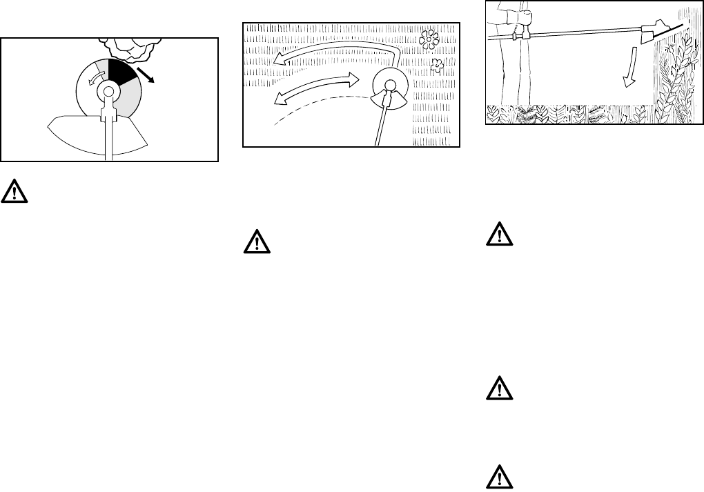
Use the power tool like a scythe to cut
grass, i.e. sweep it to and fro in an arc.
Warning!
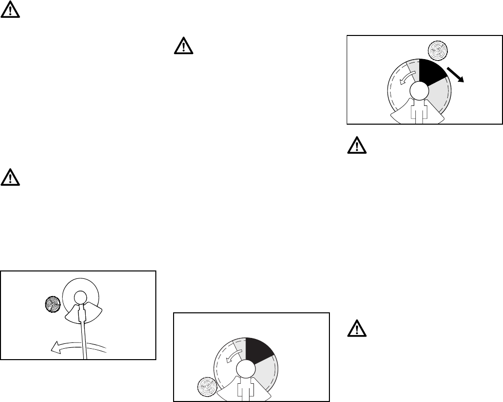
Kickout (blade thrust) is the sudden and
uncontrolled motion towards the opera-
tor's right or rear that can occur when
the shaded area (especially the darkly
shaded area) of a rotating blade comes
in contact with a solid rigid object like a
tree, rock, bush or wall. The rapid coun-
terclockwise rotation of the blade may
be stopped or slowed, and the cutting
attachment may be thrown to the right or
to the rear.
002BA135 KN
Warning!
To reduce the risk of serious or fatal
injury from blade breakage, never
attempt to use this blade to cut woody
materials.
002BA355 KN
Warning!
Exercise extreme caution when using
this method of cutting. The higher the
cutting attachment is off the ground, the
greater the risk of loss of control and of
cuttings being thrown sideways.
Warning!
When cutting woody materials, use the
left side of the blade to avoid "kickout"
(blade thrust) situations.
Warning!
Improper use of a brush knife may
cause it to crack, chip or shatter.
Thrown blade fragments may seriously
or fatally injure the operator or bystand-
ers. To reduce the risk of injury, avoid
contact with hard or solid foreign objects
such as stones, rocks or pieces of
metal.
002BA066 KN
FS 260 C, FS 360 C
English
14
Using the Circular Saw Blade
Circular saw blades are suitable for
thinning brush and cutting small trees up
to a diameter of 7 cm (2 3/4 in.). Do not
attempt to cut trees with larger
diameters, since the blade may catch or
jerk the trimmer / brushcutter forward.
This may cause damage to the blade or
loss of control of the power tool and
result in serious injury. Use a chain saw
for such work.
When a clearing saw with a circular saw
blade is used to cut down small trees,
STIHL recommends that the standard
deflector be removed and replaced by
the special limit stop deflector (see
chapter on "Mounting the Deflector").
This limit stop helps to keep the unit
positioned against the tree during the
cutting process. Inexperienced users
should place the left side of the stop
against the tree trunk before beginning
to cut. This will keep the clearing saw
against the tree during the cutting
operation and will reduce the risk of loss
of control and possible kickout
(described above and briefly again
below).
Before starting the cut, accelerate the
engine up to full throttle. Perform cut
with uniform pressure. STIHL
recommends that the circular saw blade
be applied to the right of the tree, using
the non-shaded area of the blade, as
shown in the illustration above.
When felling small trees, maintain a
distance of at least two tree lengths from
the nearest coworker.
Warning!
When cutting young saplings or other
woody materials up to 2 cm (3/4 in.) in
diameter, use the left side of the blade
to avoid "kickout" situations (see section
on "Risk of kickout (blade thrust) with all
rigid cutting blades"). Do not attempt to
cut woody material with a larger diame-
ter, since the blade may catch or jerk the
power tool forward. This may cause
damage to the blade or power tool or
loss of control of the power tool, result-
ing in personal injury. Use a circular saw
blade for such work.
Warning!
Inspect the brush knife at regular short
intervals for signs of damage. Do not
continue working with a damaged brush
knife. Resharpen the brush knife regu-
larly (when it has dulled noticeably).
002BA067 KN
Warning!
To reduce the risk that the blade will
crack and / or break, avoid all contact
with stones, rocks or the ground.
Sharpen blades in a timely manner as
specified – dull teeth may cause the
blade to crack or shatter.
002BA214 ST
Warning!
The risk of kickout is highest when cut-
ting in the darker shaded area. To
reduce the risk of kickout and resulting
injury, do not use this area of the circular
saw blade for cutting trees or shrubs.
Special techniques using the lighter
shaded areas of the blade to cut shrubs
and trees should only be used by expe-
rienced operators with specialized
training in the use and control of the
clearing saw.
Warning!
In order to reduce the risk of injury from
thrown objects or operator contact with
the blade or head, be sure to remount
the standard deflector when no longer
using a circular saw blade.
002BA068 KN

FS 260 C, FS 360 C
English
15
MAINTENANCE, REPAIR AND
STORING
Maintenance, replacement, or repair
of the emission control devices and
systems may be performed by any
nonroad engine repair establishment
or individual. However, if you make a
warranty claim for a component
which has not been serviced or
maintained properly or if
nonapproved replacement parts were
used, STIHL may deny coverage.
Strictly follow the maintenance and
repair instructions in the appropriate
sections of your instruction manual.
Wear gloves when handling or
performing maintenance on blades.
Keep blades sharp. Tighten all nuts,
bolts and screws, except the carburetor
adjustment screws, after each use.
Do not clean your machine with a
pressure washer. The solid jet of water
may damage parts of the machine.
Store the power tool in a dry and high or
locked location out of reach of children.
Before storing for longer than a few
days, always empty the fuel tank. See
chapter "Storing the Machine" in the
instruction manual.
Warning!
Use only identical STIHL replacement
parts for maintenance and repair. Use of
non-STIHL parts may cause serious or
fatal injury.
Warning!
Always stop the engine and make sure
that the cutting attachment is stopped
before doing any maintenance or repair
work or cleaning the power tool. Do not
attempt any maintenance or repair work
not described in your instruction man-
ual. Have such work performed by your
STIHL servicing dealer only.
Warning!
Use the specified spark plug, and make
sure it and the ignition lead are always
clean and in good condition. Always
press the spark plug boot snugly onto
the spark plug terminal of the proper
size. (Note: If the terminal has a detach-
able SAE adapter nut, it must be
securely attached.) A loose connection
between the spark plug and the ignition
wire connector in the boot may create
arcing that could ignite combustible
fumes and cause a fire.
Warning!
Never test the ignition system with the
spark plug boot removed from the spark
plug or with a removed spark plug, since
uncontained sparking may cause a fire.
Warning!
Do not operate your power tool if the
muffler is damaged, missing or modi-
fied. An improperly maintained muffler
will increase the risk of fire and hearing
loss. If your muffler was equipped with a
spark-arresting screen to reduce the
risk of fire, never operate your power
tool if the screen is missing or damaged.
Remember that the risk of forest fires is
greater in hot or dry weather.
Warning!
Never repair damaged cutting attach-
ments by welding, straightening or
modifying the shape. This may cause
parts of the cutting attachment to come
off and result in serious or fatal injuries.

FS 260 C, FS 360 C
English
16
Approved Combinations of Cutting Attachment, Deflector, Limit Stop and Harness
Cutting attachment Deflector, limit stop Harness
7
681BA171 KN
1
4
5
89
6
12
13
14
16
3
2
10 11 15
FS 260 C, FS 360 C
English
17
Permissible combinations
Choose the proper combination from the
table depending on the cutting
attachment!
Cutting attachments
Mowing heads
1STIHL SuperCut 40-2
2STIHL AutoCut 40-2
3STIHL TrimCut 41-2
4STIHL PolyCut 41-3
Metal cutting attachments
5Grass cutting blade 230-4
6Grass cutting blade 255-8
7Brush knife 300-3
8Circular saw blade 200 scratcher
tooth
9Circular saw blade 200 chisel tooth
10 Circular saw blade 225 scratcher
tooth
11 Circular saw blade 225 chisel tooth
Deflectors, limit stops
Deflectors
12 Deflector only for mowing heads
13 Deflector for the mowing tools
Items 5 to 7
Limit stops
14 Limit stop for circular saw blades
200
15 Limit stop for circular saw blades
225
Harnesses
16 Full harness must be used
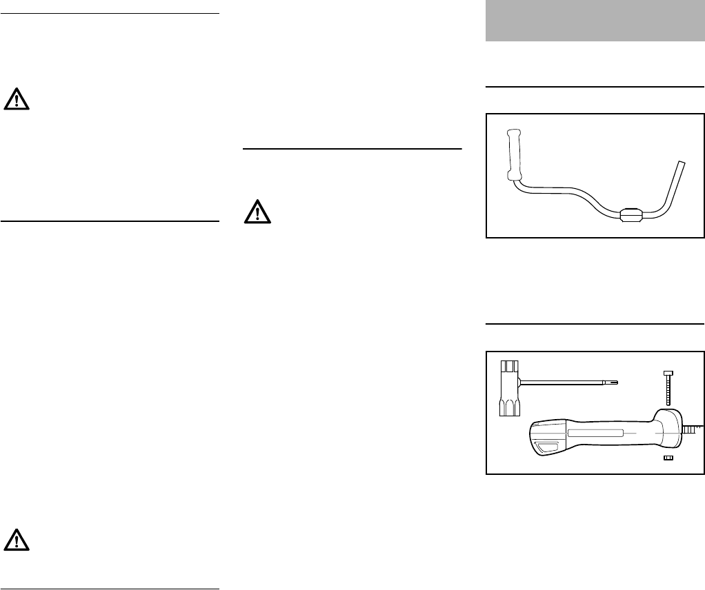
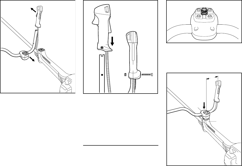
Mounting the bike handle with
swiveling handle support
The machine is supplied with the clamp
moldings (1) mounted to the
handlebar (2).
Mounting the control handle
NTake out the screw (3) and remove
the nut (4) from the control
handle (5).
For safety reasons only the
cutting attachments and deflectors
and/or limit stops within one line of
the table may be combined with
one another. Other combinations
are not permissible – risk of
accident!
Circular saw blades of other, non-
metal materials must not be used.
Warning!
Based on the cutting attachment being
used:
Choose the proper deflector in order to
reduce the risk of injury from thrown
objects and contact with the cutting
attachment.
Make sure your unit is equipped with the
proper handle and harness in order to
reduce the risk of injury from loss of con-
trol and contact with the cutting
attachment.
Use grass cutting metal blades, brush
knifes and circular saw blades on this
unit only if equipped with a bike handle.
Do not use rigid polymer blades on this
unit.
Mounting the Bike Handle
2
1
6BA018 KN
3
4
5
002BA352 KN
FS 260 C, FS 360 C
English
18
NLine up the control handle (5)
relative to the handlebar (2): The
throttle trigger (6) must point toward
the gearbox and the clamp
screw (7) toward the engine.
NHolding the control handle (5) in
that position, push it on to the end of
the handlebar (2) and line up the
holes (8).
NFit the nut (4) in the control
handle (5), insert the screw (3) and
tighten it down firmly.
Assembling the handle support
Assembly of the swivelling handle
support involves equipping the clamp
moldings with a spring and mounting
them on the handle support.
NUse the spring (9) from the parts kit
supplied with the machine.
NPlace the spring (9) in the lower
clamp molding (10).
NPosition the clamp moldings (1) with
handlebar (2) on the handle
support (11).
7
5
6BA002 KN
6
2
8
6BA019 KN
2
83
5
4
6BA001 KN
9
10
11
1
6BA020 KN
2
A
FS 260 C, FS 360 C
English
19
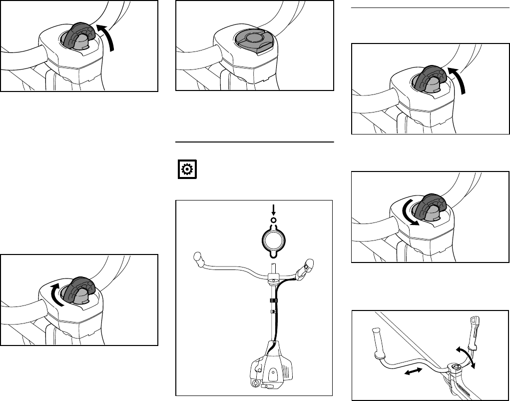
NRaise the grip of the wing screw (7)
to the upright position.
NTurn the wing screw
counterclockwise as far as stop.
NPush the wing screw into the handle
support as far as stop and then
screw it down – but do not finally
tighten yet.
NAdjust the handlebar (2) so that
distance A is no more than 15 cm.
NLine up the handlebar at a right
angle to the drive tube.
NTurn the wing screw clockwise as
far as stop.
NFold the grip of the wing screw down
so that it is flush.
FS 260 C: Fitting the throttle cable
NAttach the throttle cable (12) to the
retainer (13).
Adjusting the handlebar
Opening the wing screw
NRaise the grip of the wing screw to
the upright position.
NTurn the wing screw
counterclockwise until the handle
support can be moved.
NMove the handlebar to the required
position.
6BA003 KN
2
7
6BA005 KN
Do not kink the throttle cable or
lay it in tight radii – make sure the
throttle trigger moves freely.
6BA006 KN
12
13
002BA439 KN
13
12
6BA023 KN
6BA004 KN
6BA007 KN
FS 260 C, FS 360 C
English
20
Closing the wing screw
NTurn the wing screw clockwise as
far as stop.
NFold the grip of the wing screw down
so that it is flush.
Swiveling the handlebar
Transport position
NLoosen the wing screw (7) and
unscrew it until the handlebar (2)
can be turned clockwise.
NTurn the handlebar 90° and then
swing the handles down.
NTighten down the wing screw (7)
firmly.
Working position
NReverse the sequence described
above to swing the handles up and
turn the handlebar
counterclockwise.
Using the proper deflector
6BA005 KN
6BA006 KN
7
6BA008 KN
2
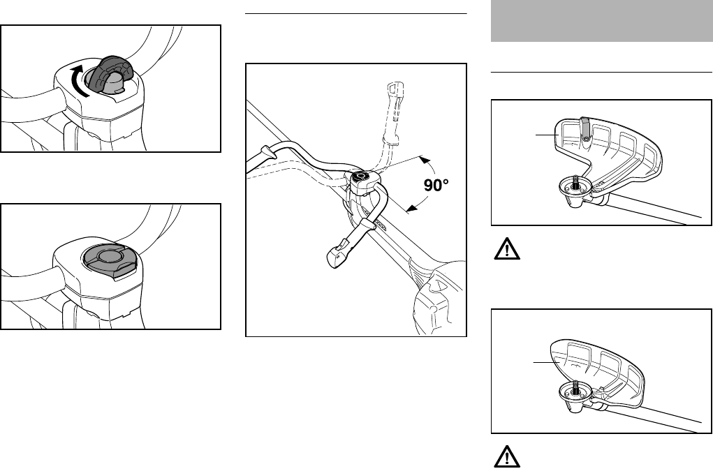
Mounting the Deflector
Deflector (1) is approved only for
mowing heads, thus deflector (1)
must be attached before attaching
a mowing head.
Deflector (2) is approved only for
grass cutting blades, thus
deflector (2) must be attached
before attaching a grass cutting
blade.
1
002BA401 KN
2
002BA402 KN
FS 260 C, FS 360 C
English
21
Mounting the deflector
Deflectors (1-3) are attached to the
gearbox in the same manner.
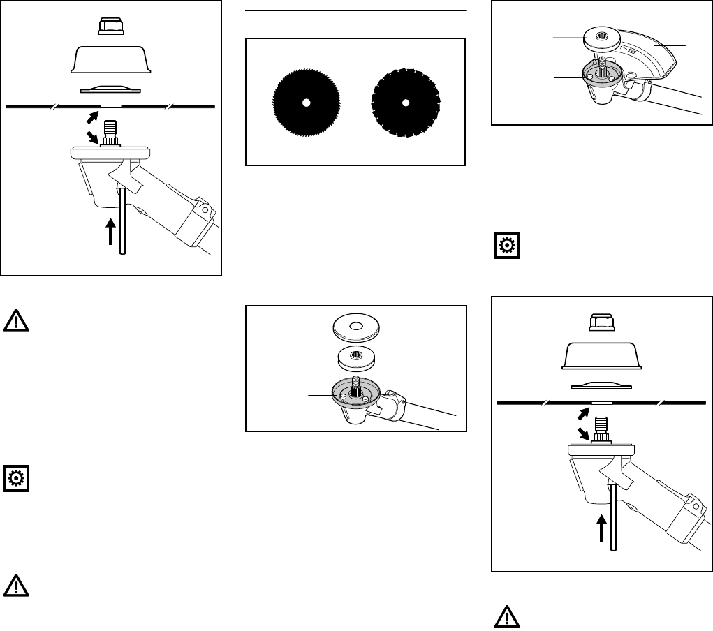
NSet the deflector on the gearbox (5),
Nscrew in and tighten the screws (6)
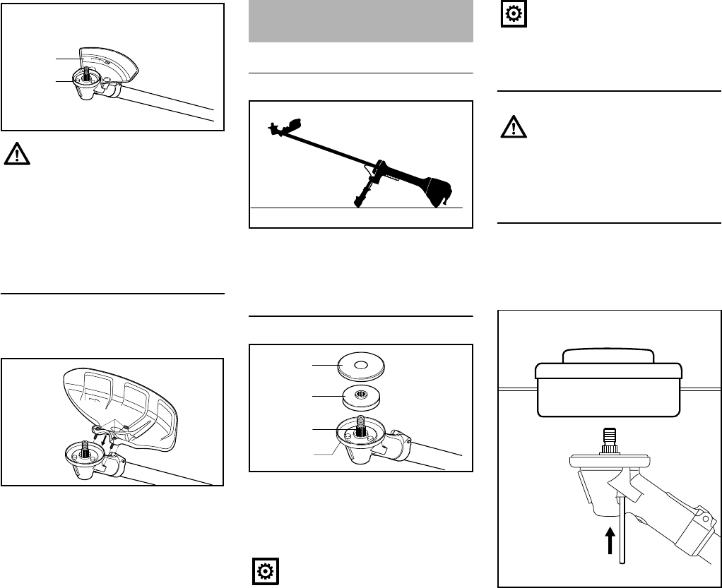
Preparing the machine
NLay down the machine so that the
mount for the cutting attachment
faces upward
Attaching the thrust plate
NPush the thrust plate (1) and guard
washer (2) onto the shaft (3)
The machine is equipped at the factory
with a guard ring (4) for mowing tools.
Mounting the cutting attachment
Mounting the mowing heads
STIHL SuperCut, STIHL AutoCut,
STIHL TrimCut, STIHL PolyCut
NUse the guard ring for mowing tools
NAttach the deflector for mowing
heads
NBlock the shaft
NTurn the mowing head
counterclockwise onto the shaft (1)
and tighten
Limit stop (3) is approved only for
circular saw blades, thus limit
stop (3) must be attached and
guard ring (4) replaced before
attaching a circular saw blade,
see "Mounting the cutting
attachment" / "Mounting circular
saw blades".
3
002BA433 KN
4
6
5
002BA434 KN
Mounting the Cutting
Attachment
The thrust plate (1) on the
gearbox is required for securing
all cutting attachments.
002BA406 KN
002BA407 KN
1
2
3
4
The guard washer (2) on the
gearbox is required for securing
all cutting attachments with the
exception of circular saw blades.
Use the appropriate deflector for
the cutting attachment – see
"Mounting the deflector".
1
002BA408 KN
FS 260 C, FS 360 C
English
22
Keep the information sheet for the
mowing head in a safe place.
Removing the mowing head
NBlock the shaft
NUnscrew the mowing head
clockwise
Feeding out mowing line
A detailed description is contained in the
information sheet for the respective
mowing head.
SuperCut Mowing Head
Line is fed out automatically during
mowing and shortened to optimum
length by the blade on the deflector. Line
is fed out only if both ends of the line are
still at least 6 cm long.
AutoCut Mowing Head
NHold the machine over an area of
lawn with the engine running
(mowing head must rotate)
NTap the mowing head on the ground
– line is fed out automatically and
shortened to optimum length by the
blade on the deflector
Line is fed out only if both ends of the
line are still at least 2.5 cm long.
TrimCut Mowing Head
NPull up the spool housing – turn
counterclockwise – approx. 1/6 turn
– until it engages – and then allow it
to spring back
NPull the ends of the line outward
Repeat operation as needed until both
ends of the line are approx. 13 cm long.
A rotary movement from one click to the
next releases approx. 4 cm of line.
PolyCut Mowing Head
Proceed as described in the mowing
head information sheet.
Attaching grass cutting blades,
brush knives
With the grass cutting blade 255-8 (1),
the cutting edges must face clockwise.
Cutting attachments with 3 or
4 blades (2, 3) can face in any direction
– turn over these cutting attachments
periodically to avoid uneven wear.
NUse the guard ring for mowing tools
NAttach the deflector for metal
mowing tools
Remove the tool used to block the
shaft.
Always switch off the engine to
fed out mowing line by hand –
otherwise there is a risk of injury!
Always switch off the engine to
load the mowing head by hand –
otherwise there is a risk of injury!
FS 260 C, FS 360 C
English
23
NPosition cutting attachment (1)
NFit the thrust washer (2) – curvature
faces upward
NPosition thrust plate (3)
NBlock the shaft
NScrew on the nut (4)
counterclockwise and tighten
Removing cutting attachments
NBlock the shaft
NUnscrew the nut clockwise
Attaching circular saw blades
With circular saw blades, the cutting
edges must face clockwise.
For attaching circular saw blades, a limit
stop set is available as a special
accessory that contains a limit stop and
a guard ring for circular saw blades.
Change guard ring
NRemove guard washer (3) and
thrust plate (4)
NRemove guard ring (5) for mowing
tools
NAttach guard ring (6) for circular saw
blades
NPush thrust plate (4) onto the shaft
NAttach limit stop (7) for circular saw
blades
Mounting the cutting attachment
NPosition cutting attachment (1)
The collar (a) must engage the
hole (b) in the cutting attachment!
Remove the tool used to block the
shaft.
A nut that moves too easily should
be replaced.
2
3
1
4
002BA409 KN
b
a
681BA165 KN
002BA424 KN
4
3
5
Do not use the guard washer (3)
for circular saw blades.
The collar (a) must engage the
hole (b) in the cutting attachment!
7
002BA425 KN
6
4
2
3
1
4
002BA423 KN
b
a

FS 260 C, FS 360 C
English
24
NFit the thrust washer (2) – curvature
faces upward
NPosition thrust plate (3)
A thrust plate (3) for sawing use, with
which the entire cutting depth of the
circular saw blade can be used, is
available as a special accessory.
NBlock the shaft
NScrew on the nut (4)
counterclockwise and tighten
Removing cutting attachments
NBlock the shaft
NUnscrew the nut clockwise
This engine is certified to operate on
unleaded gasoline and the STIHL two-
stroke engine oil at a mix ratio of 50:1.
Your engine requires a mixture of high-
quality gasoline and quality two-stroke
air cooled engine oil.
Use mid-grade unleaded gasoline with a
minimum octane rating of 89 (R+M/2). If
the octane rating of the mid-grade
gasoline in your area is lower, use
premium unleaded fuel.
Fuel with a lower octane rating may
increase engine temperatures. This, in
turn, increases the risk of piston seizure
and damage to the engine.
The chemical composition of the fuel is
also important. Some fuel additives not
only detrimentally affect elastomers
(carburetor diaphragms, oil seals, fuel
lines, etc.), but magnesium castings and
catalytic converters as well. This could
cause running problems or even
damage the engine. For this reason
STIHL recommends that you use only
nationally recognized high-quality
unleaded gasoline!
Use only STIHL two-stroke engine oil or
equivalent high-quality two-stroke
engine oils that are designed for use
only in air cooled two-cycle engines.
We recommend STIHL 50:1 two-stroke
engine oil since it is specially formulated
for use in STIHL engines.
Do not use BIA or TCW rated (two-
stroke water cooled) mix oils or other
mix oils that state they are for use in both
water cooled and air cooled engines
(e.g., outboard motors, snowmobiles,
chain saws, mopeds, etc.).
Take care when handling gasoline.
Avoid direct contact with the skin and
avoid inhaling fuel vapor. When filling at
the pump, first remove the canister from
your vehicle and place the canister on
the ground before filling. Do not fill fuel
canisters that are sitting in or on a
vehicle.
The canister should be kept tightly
closed in order to avoid any moisture
getting into the mixture.
The machine‘s fuel tank and the canister
in which fuel mix is stored should be
cleaned as necessary.
Fuel mix ages
Only mix sufficient fuel for a few days
work, not to exceed 3 months of storage.
Store in approved fuel-canisters only.
When mixing, pour oil into the canister
first, and then add gasoline. Close the
canister and shake it vigorously by hand
to ensure proper mixing of the oil with
the fuel.
Dispose of empty mixing-oil canisters
only at authorized disposal locations.
Remove the tool used to block the
shaft.
A nut that moves too easily should
be replaced.
Fuel
Gaso-
line
Oil (STIHL 50:1 or equiva-
lent high-quality oils)
US gal. US fl.oz
12.6
2 1/2 6.4
5 12.8
FS 260 C, FS 360 C
English
25
Preparations
NOn level ground, position the
machine so that the filler cap is
facing up.
NBefore fueling, clean the filler cap
and the area around it to ensure that
no dirt falls into the tank.
Always thoroughly shake the mixture in
the canister before fueling your
machine.
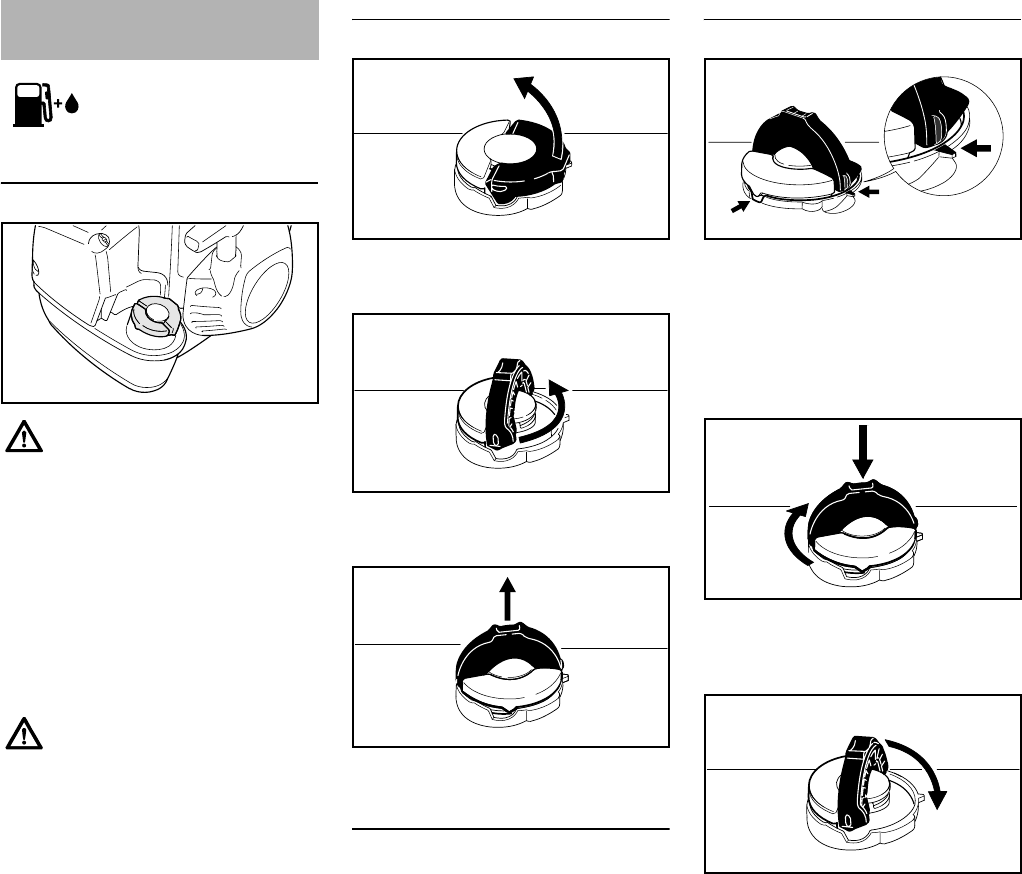
Opening
NRaise the grip into an upright
position.
NTurn the cap counterclockwise
(approx. 1/4 turn).
NRemove fuel filler cap.
Refueling
Take care not to spill fuel while fueling
and do not overfill the tank.
Closing
With grip in an upright position:
NInsert the cap – positioning marks
on the cap and the fuel tank opening
must line up.
NThe cap should drop fully into the
opening in this position.
NWhile pressing the cap down, twist it
firmly clockwise as far as it will go
(approx. 1/4 turn).
NFold down the grip.
Fueling
When fueling on a slope, always
position the machine so that the
filler cap is facing uphill.
In order to reduce the risk of burns
or other personal injury from
escaping gas vapor and fumes,
remove the fuel filler cap carefully
so as to allow any pressure build-
up in the tank to release slowly.
9926BA005 KN
001BA218 KN
001BA219 KN
001BA224 KN
001BA220 KN
001BA221 KN
001BA222 KN
FS 260 C, FS 360 C
English
26
Checking for proper closure
NThe lug on the grip must engage
entirely in the recess (arrow), and
the grip must lie completely flush
with the top of the cap.
NGrip the cap and check for
tightness.
NIf the cap can be moved, it is not
properly installed.
Misalignment of the cap parts
NIf the cap does not drop fully into the
opening when the positioning marks
line up and/or if the cap does not
tighten properly when twisted, the
base of the cap may be rotated out
of position vis-à-vis the top.
NSuch misalignment can result from
handling, cleaning or an improper
attempt at tightening.
NTo correct a misalignment, turn the
cap (with the grip up) until it drops
fully into the tank opening.
NTwist the cap counterclockwise as
far as it will go (approx. 1/4 turn) –
this will twist the base of the cap into
the correct position.
NTwist the cap clockwise, closing it
normally – see the sections
"Closing" and "Checking for proper
closure."
NIf your cap still does not tighten
properly, it may be damaged or
broken; immediately stop use of the
unit and take it to your authorized
STIHL dealer for repair.
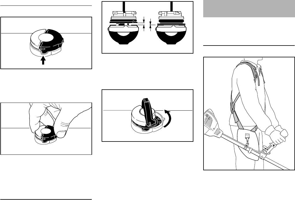
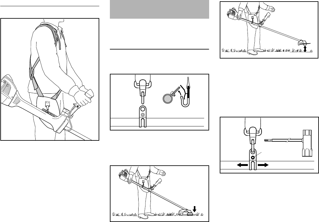
Fitting the full harness is described in
detail in the instruction sheet supplied.
FS 260 C
NPut on the full harness (1).
NAdjust the length of the strap so that
the carabiner (2) is about a hand’s
width below your right hip.
NBalance the machine – see
"Balancing the Machine".
001BA223 KN
001BA225 KN
Left: Base of improperly aligned
cap (with open space)
Right: Base of cap correctly posi-
tioned for installation
001BA227 KN
001BA226 KN
Fitting the Full Harness
002BA386 KN
1
2
FS 260 C, FS 360 C
English
27
FS 360 C
NPut on the full harness (1).
NAdjust the length of the strap so that
the carabiner (2) is about a hand’s
width below your right hip.
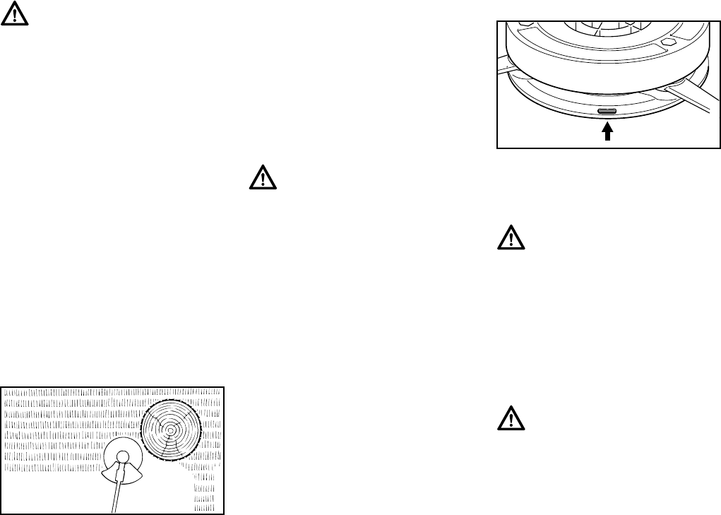
NAttach the spring hook to the
machine's perforated strip (3).
Find the right attachment point for the
cutting attachment you are using – see
"Balancing the Machine".
The type and version of the harness and
snap hook depend on the market.
FS 260 C
Connect machine to harness
NHook the snap hook (1) into the
carrying ring (2) on the drive tube
Hanging positions
Mowing heads, grass cutting blades and
brush knives should rest lightly on the
ground.
Circular saw blades should "hover"
approx. 8 in. (20 cm) above the ground.
Carry out the following steps to attain the
proper hanging position:
Letting the machine swing until it
stops moving
NUndo the screw (3)
NAdjust carrying ring (2) – tighten
screw lightly – let the machine swing
until it stops moving – check
hanging position
Once the proper hanging position has
been attained:
NTighten the screw on the carrying
ring
3
002BA411 KN
1
2
Balancing the
Trimmer/Brushcutter
1
2
1
2
002BA387 KN
002BA388 KN
002BA389 KN
3
2
002BA390 KN
FS 260 C, FS 360 C
English
28
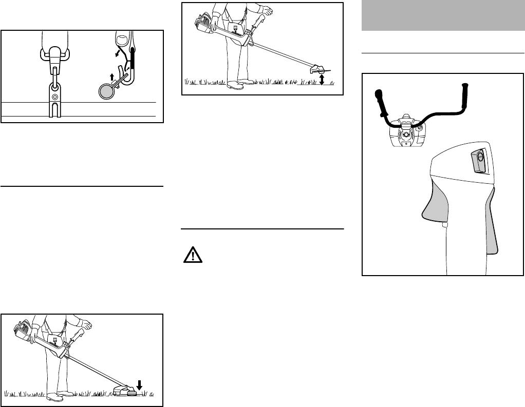
Disconnecting the machine from the
harness
NPress the spring on the snap
hook (1) and remove the carrying
ring (2) from the hook
FS 360 C
The machine will balance differently
depending on the cutting attachment
mounted.
NLet the machine swing on the
harness until it stops moving –
change the connection point if
necessary
Hanging positions
Mowing heads, grass cutting blades and
brush knives should rest lightly on the
ground.
Circular saw blades should "hover"
approx. 8 in. (20 cm) above the ground.
Disconnecting the machine from the
harness
NPress the spring on the snap hook
and remove the perforated strip
from the hook
Putting down the machine in an
emergency
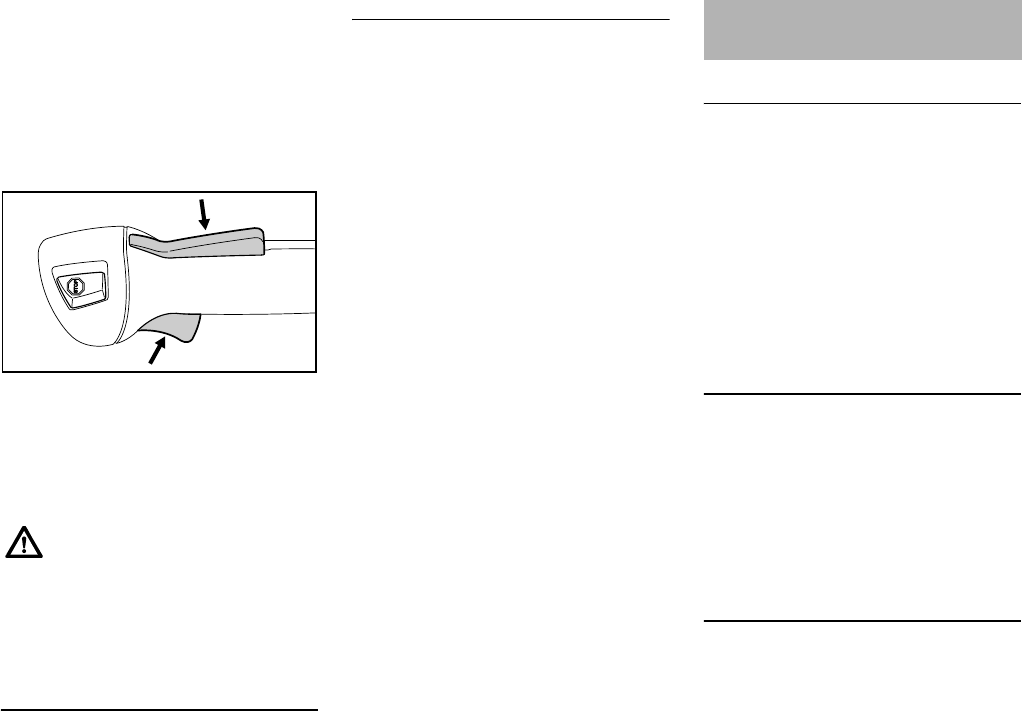
Controls
1Throttle trigger lockout
2Throttle trigger
3Stop switch with Run and Stop
positions. Push the stop switch
(STOP) to switch off the ignition.
Function of stop switch and ignition
system
The stop switch is normally in the Run
position: Ignition is on in this position –
the engine is ready to start and may be
started. The ignition is switched off when
the stop switch is depressed. It is
automatically switched on again after
the engine comes to a standstill.
1
2
1
2
002BA391 KN
6BA009 KN
As soon as it becomes apparent
that a dangerous situation is
developing, the machine must be
put down quickly. To put down the
machine, proceed as in
"Disconnecting the machine from
the harness". Practice setting
down the machine quickly. In
order to avoid damage, when
practicing, do not throw the
machine on the ground.
6BA010 KN
Starting / Stopping the
Engine
1
002BA392 KN
2
3
FS 260 C, FS 360 C
English
29
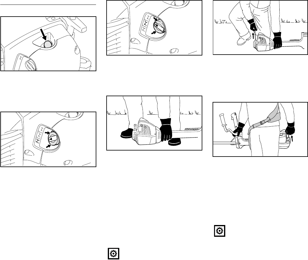
Starting the Engine
NPress the fuel pump bulb (4) at least
five times – even if the bulb is
already filled with fuel.
Cold engine (cold start)
NPress in the outer edge (arrows) of
the choke knob (5) and then turn it
to g.
Also use this setting if the engine has
been running but is still cold.
Hot engine (hot start)
The engine has reached normal
operating temperature, then shut down
and restarted after more than 5 minutes.
NPress in the outer edge (arrows) of
the choke knob (5) and then turn it
to<.
Starting
NPlace the unit on the ground: It must
rest securely on the engine's guard
plate and the deflector. Check that
the cutting attachment is not
touching the ground of any other
obstacles.
NMake sure you have a firm footing –
either standing, stooping or
kneeling.
NHold the unit firmly on the ground
with your left hand and press down
– do not touch the throttle trigger or
lockout lever.
NHold the starter grip with your right
hand.
Alternative method of starting:
Engine warm and the machine hanging
from the harness.
NHold the machine firmly with your
right hand on the drive tube, handle
support or handlebar.
NWith the machine behind you, press
it against the left side of your body.
NHold the starter grip with your left
hand.
NPull the starter grip steadily.
4
9926BA006 KN
5
9926BA007 KN
5
Do not stand or kneel on the drive
tube.
9926BA008 KN
5
6BA011 KN
Do not pull out the starter rope all
the way – it might otherwise
break.
6BA012 KN
6BA013 KN
FS 260 C, FS 360 C
English
30
NDo not let the starter grip snap back.
Guide it slowly back into the housing
so that the starter rope can rewind
properly.
NContinue cranking until the engine
runs.
As soon as the engine runs
NPress down the throttle trigger
interlock and open the throttle – the
choke lever moves to the run
position F. After a cold start, warm
up the engine by opening the
throttle several times.
Your machine is now ready for
operation.
Stopping the Engine
NOperate the stop switch – the
engine stops – release the stop
switch – it springs back to the run
position.
Other hints on starting
At very low outside temperatures
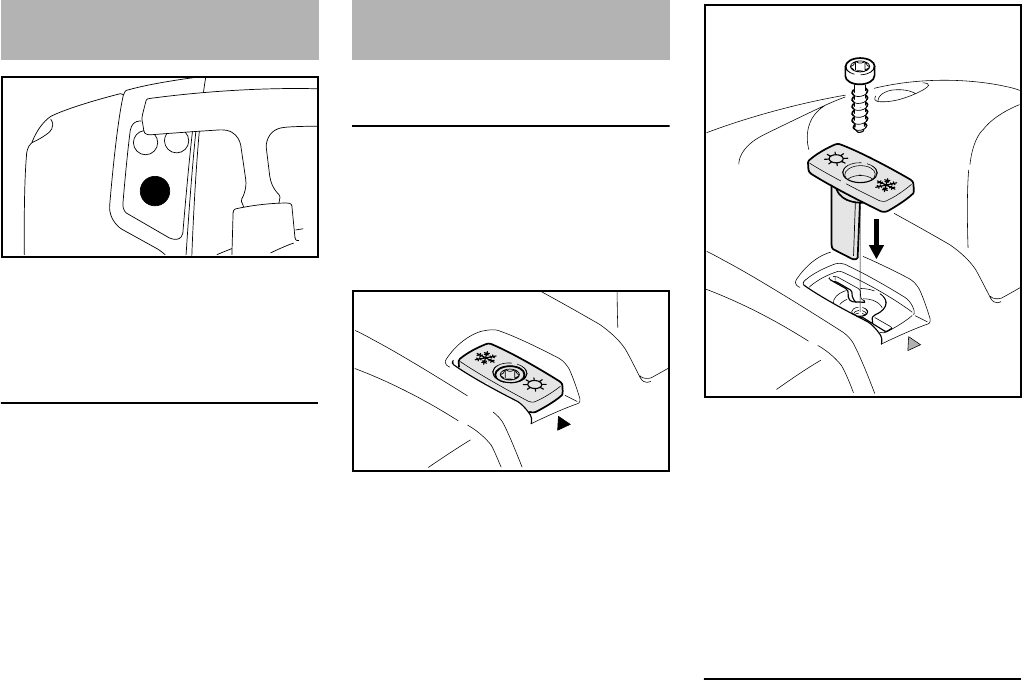
NSet the engine to winter operation if
necessary, see "Winter operation".
Engine stalls in cold start position g
or under acceleration
NMove the choke lever to < and
continue cranking until the engine
runs.
Engine does not start in hot start
position <
NMove the choke lever to g and
continue cranking until the engine
runs.
If the engine does not start
NCheck that all settings are correct.
NCheck that there is fuel in the tank
and refuel if necessary.
NCheck that the spark plug boot is
properly connected.
NRepeat the starting procedure.
Fuel tank run until completely dry
NAfter refueling, press the fuel pump
bulb at least five times – even if the
bulb is filled with fuel.
NSet the choke lever to suit the
engine temperature.
NStart the engine.
During break-in period
A factory-new machine should not be
run at high revs (full throttle off load) for
the first three tank fillings. This avoids
unnecessary high loads during the
break-in period. As all moving parts
have to bed in during the break-in
period, the frictional resistances in the
engine are greater during this period.
The engine develops its maximum
power after about 5 to 15 tank fillings.
During Operation
After a long period of full throttle
operation, allow the engine to run for a
short while at idle speed so that engine
heat can be dissipated by the flow of
cooling air. This protects engine-
mounted components (ignition,
carburetor) from thermal overload.
After Finishing Work
Storing for a short period: Wait for the
engine to cool down. Empty the fuel tank
and keep the machine in a dry place,
well away from sources of ignition, until
you need it again. For longer out-of-
service perionds – see "Storing the
Machine".
Make sure the carburetor is
correctly adjusted. The cutting
attachment must not rotate when
the engine is idling.
6BA014 KN
Operating Instructions

FS 260 C, FS 360 C
English
31
Dirty air filters reduce engine power,
increase fuel consumption and make
starting more difficult.
If there is a noticeable loss of engine
power
NSet the choke lever to g.
NLoosen the screws (1).
NRemove the filter cover (2).
NClean away loose dirt from around
the filter (3) and inside the filter
cover.
The filter (3) consists of a pleated paper
filter element.
NRemove and check the filter
element (3) – replace if dirty or
damaged.
NFit the filter in the filter housing.
NFitting the filter cover
Machines with "cover plate kit" for
winter operation
The filter (3) consists of a synthetic
fabric element, see also "Winter
operation".
NKnock the filter (3) out on the palm
of your hand or blow it clear with
compressed air from the inside
outwards.
In case of stubborn dirt or sticky filter
fabric:
NWash the filter in a clean, non-
flammable solution (e.g. warm
soapy water) and then dry.
Always replace a damaged filter.
Exhaust emissions are controlled by the
design of the fundamental engine
parameters and components (e.g.
carburation, ignition, timing and valve or
port timing) without the addition of any
major hardware.
Cleaning the Air Filter
9926BA013 KN
1
3
9926BA014 KN
2
Engine Management
FS 260 C, FS 360 C
English
32
The carburetor has been set at the
factory to provide an optimum fuel-air
mixture under most operating
conditions.
Adjusting idle speed
Engine stops while idling
NTurn the idle speed screw (LA)
slowly clockwise until the engine
runs smoothly.
Cutting tool rotates when engine is
idling
NTurn the idle speed screw (LA)
slowly counterclockwise until the
cutting attachment stops moving.
At temperatures below
+50°F(+10°C)
Pre-heat carburetor
Moving a shutter causes heated air to be
drawn in from around the cylinder and
mixed with cold air in order to prevent
carburetor icing.
An arrow on the shroud (1) shows the
position of the shutter (2) for summer or
winter operation. Key to symbols:
–Symbol "Sun" = summer operation
–Symbol "Snowflake" = winter
operation
NUnscrew and remove screw (3) on
shutter
NRemove shutter (2) from the shroud
NRotate shutter (2) from summer
position to winter position and
reinsert
NScrew the screw (3) through the
shutter into the shroud
At temperatures between
+50 °F (+10 °C) and +70 °F (+20 °C)
Within this temperature range, the
machine can normally be operated with
the shutter (2) in summer position.
Change the position of the shutter as
necessary.
Adjusting the Carburetor
9926BA015 KN
HL
LA
Winter Operation
2
1
9926BA016 KN
2
9926BA017 KN
3
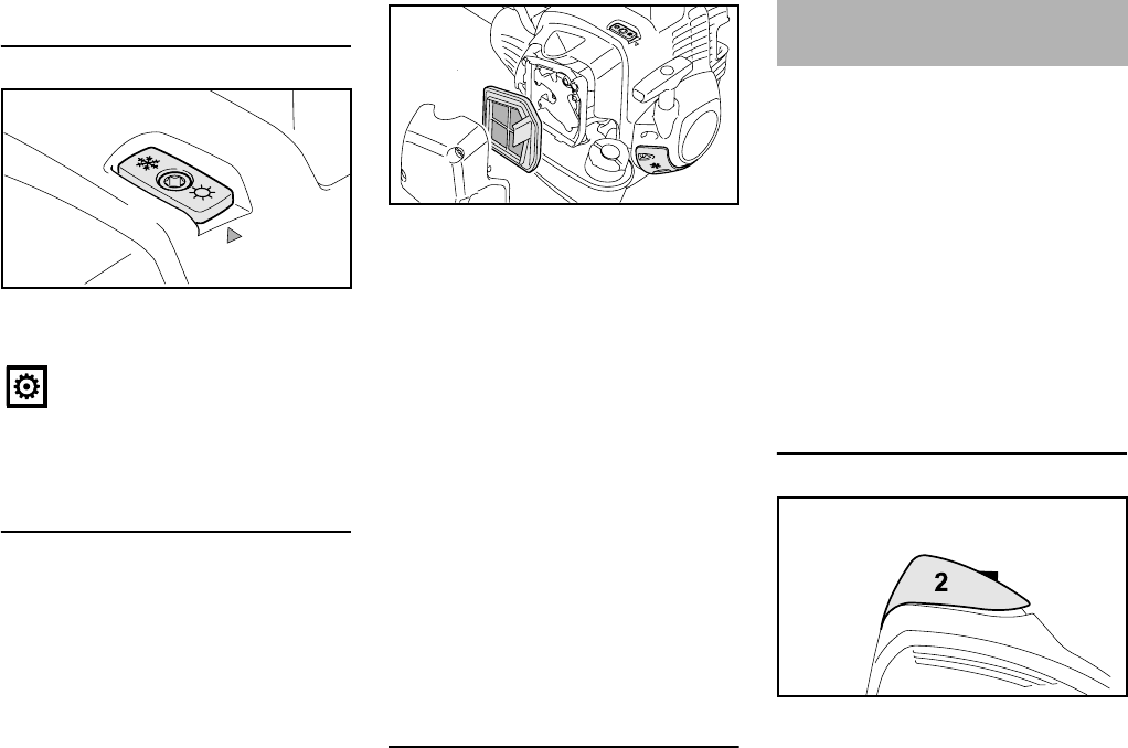
FS 260 C, FS 360 C
English
33
At temperatures above
+70 °F (+20 °C)
NAlways return the shutter (2) to
summer position
At temperatures below +14 °F (-10 °C)
Under extreme winter conditions with
the following conditions
–At temperatures below +14 °F
(-10 °C)
–Powdered or drifting snow
use of the "cover plate kit", which is
available as a special accessory, is
recommended.
The "cover plate kit" contains the
following parts for covering the machine:
4Cover plate for partially covering the
slits in the starter housing
5Filter insert made of cloth and
plastic for the air filter
–O-ring for the filler cap
–Information sheet describing
conversion of the machine
After installation of the cover plate kit:
NSet shutter (2) to winter operation
Nif the chain saw is extremely cold
(frost formation) – after starting,
bring the engine up to operating
temperature at increased idle speed
(cutting attachment rotates!)
At temperatures above
+14 °F (-10 °C)
NReconvert the machine and replace
the parts from the "cover plate kit"
with the parts for summer operation
The O-ring installed on the filler cap with
the "cover plate kit" can remain on the
machine.
Depending on the ambient temperature:
NSet shutter (2) to summer or winter
operation
If engine is down on power, difficult to
start or runs poorly at idling speed, first
check the spark plug.
Fit a new spark plug after approx. 100
operating hours or earlier if the
electrodes are badly eroded.
Wrong fuel mix (too much engine oil in
the gasoline), a dirty air filter and
unfavorable running conditions (mostly
at part throttle etc.) affect the condition
of the spark plug. These factors cause
deposits to form on the insulator nose
which may result in trouble in operation.
Removing the Spark Plug
NRotate the screw (1) in the cap (2)
until the screw head projects from it.
Do not use the machine in winter
operation at temperatures above
+70 °F (+20 °C), otherwise there
is a risk of engine damage due to
overheating!
2
9926BA018 KN
4
5
9926BA019 KN
2
Spark Plug
1
9926BA020 KN
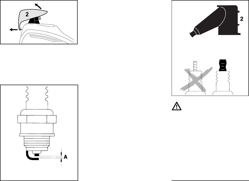
FS 260 C, FS 360 C
English
34
NLift the front of the cap (2) and push
it to the rear to disengage.
NLeave the cap to one side.
NPull off the spark plug boot (3).
NUnscrew the spark plug.
Wrong fuel mix (too much engine oil in
the gasoline), a dirty air filter and
unfavorable running conditions (mostly
at part throttle etc.) affect the condition
of the spark plug. These factors cause
deposits to form on the insulator nose
which may result in trouble in operation.
If engine is down on power, difficult to
start or runs poorly at idling speed, first
check the spark plug.
NRemove spark plug – see "Starting /
Stopping the Engine".
NClean dirty spark plug.
NCheck electrode gap (A) and
readjust if necessary – see
"Specifications".
NUse only resistor type spark plugs of
the approved range.
Rectify problems which have caused
fouling of spark plug:
NToo much oil in fuel mix.
NDirty air filter.
NUnfavorable running conditions,
e.g. operating at part load.
Fit a new spark plug after approx. 100
operating hours or earlier if the
electrodes are badly eroded.
Installing the Spark Plug
NScrew the spark plug into the
cylinder.
NPress the spark plug boot firmly
onto the spark plug.
3
9926BA021 KN
000BA002 KN
Warning!
To reduce the risk of fire and burn injury,
use only spark plugs authorized by
STIHL. Always press spark plug boot (2)
snugly onto spark plug terminal (1) of
the proper size. (Note: If terminal has
detachable SAE adapter nut, it must be
attached.) A loose connection between
spark plug boot and ignition wire con-
nector in the boot may create arcing that
could ignite combustible fumes and
cause a fire.
0
00BA036 TR
1
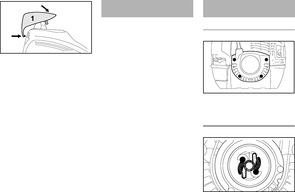
FS 260 C, FS 360 C
English
35
NFit the cap (1) on the shroud from
the rear and push the lug (2) into the
opening (3) in the shroud at the
same time.
NSwing the cap forwards onto the
shroud, insert and tighten down the
screw (4) firmly.
If engine running behavior is
unsatisfactory even though the air filter
is clean and the carburetor and throttle
cable are properly adjusted, the cause
may be the muffler.
Have the muffler checked by a servicing
dealer for contamination
(carbonization).
STIHL recommends that you have
servicing and repair work carried out
exclusively by an authorized STIHL
servicing dealer.
Removing the rewind starter
NTake out the screws (1).
NLift away the rewind starter.
Removing the rope rotor
NUse a screwdriver or suitable pliers
to remove the spring clip (2) from
the starter post.
NCarefully remove the E-clip (3).
4
3
2
9926BA022 KN
Engine Running Behavior Replacing the Starter Rope
and Rewind Spring
1 1
1 1
9926BA023 KN
32
9926BA024 KN
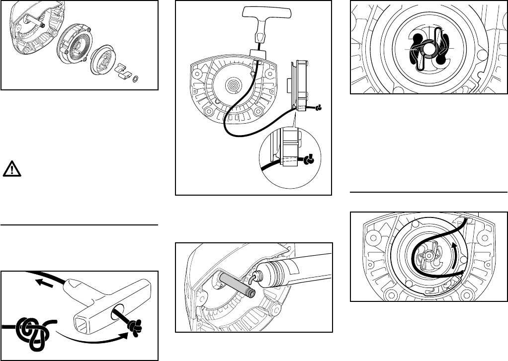
FS 260 C, FS 360 C
English
36
NCarefully remove the rope rotor (4)
with carrier (5), pawls (6) and
washer (7).
NPut the carrier (5) down so that the
pawls and washer cannot fall out.
Replacing a broken starter rope
NRemove the remaining rope from
the rotor and starter grip.
NThread the new rope through the
starter grip and tie one of the knots
shown.
NPull the knot back into the grip.
NThread the rope through the top of
the guide bushing (1) and rope
rotor (2).
NCoat starter post uniformly with
STIHL gear lubricant – see "Special
Accessories".
NSlip the rope rotor with carrier,
pawls and washer over the starter
post – turn it back and forth to
engage the anchor loop of the
rewind spring.
NFit the E-clip (3) in the groove in the
starter post.
NPush the spring clip (4) into position
– it must point counterclockwise as
shown and engage the pegs on the
pawls (5).
Tensioning the rewind spring
NMake a loop in the unwound starter
rope and use it to turn the rope rotor
six full revolutions
counterclockwise.
NHold the rotor steady.
NPull out and straighten the twisted
rope.
NRelease the rope rotor.
NRelease the rope slowly so that it
winds onto the rotor.
The rewind spring may pop out
and uncoil during this operation –
take care to avoid the risk of
injury.
5
6
9926BA025 KN
4
7
9926BA026 KN
1
9926BA027 KN
2
9926BA035 KN
34
9926BA028 KN
55
9926BA029 KN
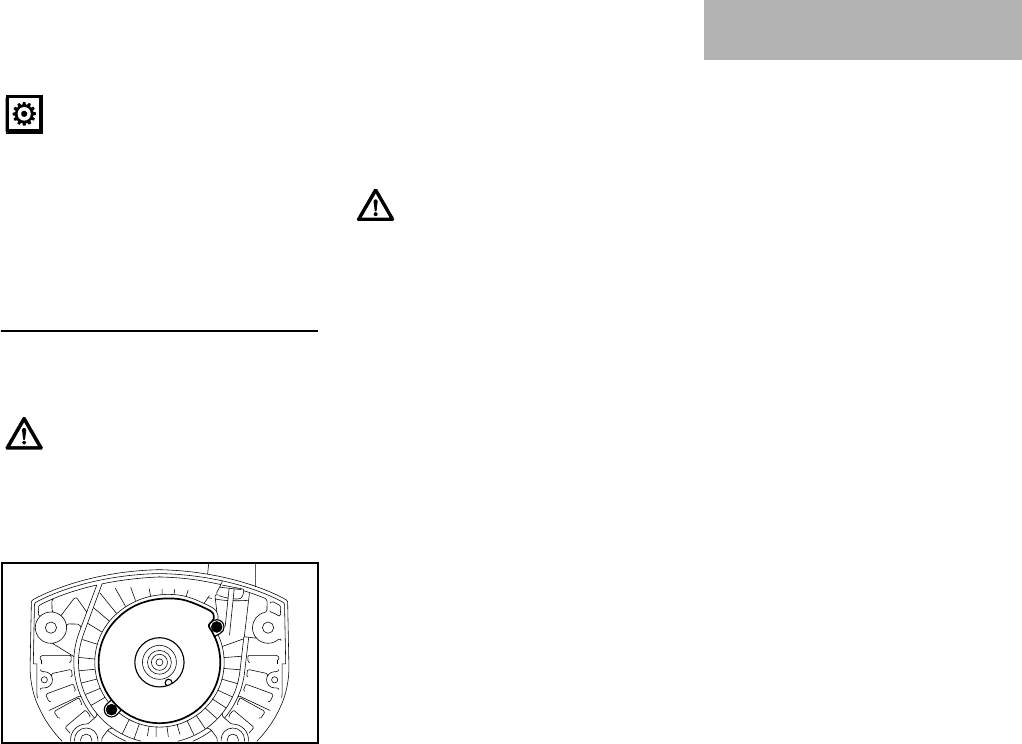
FS 260 C, FS 360 C
English
37
The starter grip must sit firmly in the rope
bushing. If the grip droops to one side:
Add one more turn on the rope rotor to
increase spring tension.
NTake one turn of the rope off the
rotor.
NInstall the rewind starter.
Replacing a broken rewind spring
NRemove the rope rotor as described
in "Removing the rope rotor".
NTake out the screws (1).
NRemove the spring housing and
pieces of spring.
NLubricate the new, ready-to-fit
replacement spring in the new
spring housing with a few drops of
resin-free oil – see "Special
Accessories".
NFit the replacement spring with
spring housing – the bottom plate
must face up.
NFit the screws.
NInstall the rope rotor as described in
"Replacing a broken rewind spring".
NTension the rewind spring as
describedf in "Tensioning the
rewind spring".
NInstall the rewind starter.
For periods of 3 months or longer
NDrain and clean the fuel tank in a
well ventilated area.
NDispose of fuel properly in
accordance with local
environmental requirements.
NRun the engine until the carburetor
is dry – this helps prevent the
carburetor diaphragms sticking
together.
NRemove, clean and inspect the
cutting attachment.
NThoroughly clean the machine –
pay special attention to the cylinder
fins and air filter.
NStore the machine in a dry and
secure location – out of the reach of
children and other unauthorized
persons.
When the starter rope is fully
extended it must still be possible
to rotate the rotor another full turn.
If this is not the case, the spring is
overtensioned and could break.
The bits of the spring may still be
under tension and could fly apart
when you remove the rope rotor
and spring housing. To reduce
the risk of injury, wear face
protection and work gloves.
1
9926BA030 KN
1
If the spring pops out of the
housing during installation: Wear
face protection and work gloves
and refit the spring in the spring
housing – clockwise – from the
outside inwards.
Storing the Machine
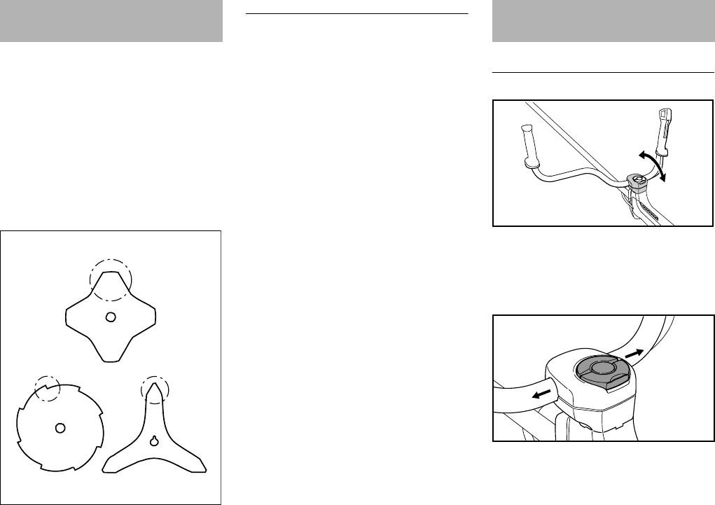
FS 260 C, FS 360 C
English
38
NUse a sharpening file (special
accessory) to sharpen dull cutting
attachments. In case of more
serious wear or nicks: Resharpen
with a grinder or have the work done
by a dealer – STIHL recommends a
STIHL servicing dealer.
NResharpen frequently, take away as
little material as possible: two or
three strokes of the file are usually
enough.
NResharpen the cutters (1) uniformly
– do not alter the contour or the
parent blade (2) in any way.
See cutting attachment packaging for
additional sharpening instructions.
Balancing
NAfter resharpening about 5 times,
check the cutting attachment for
out-of-balance on a STIHL balancer
(special accessory) or have it
checked by a dealer and re-
balanced as necessary – STIHL
recommends a STIHL servicing
dealer.
Clamped area of handlebar
NCheck the freedom of movement of
the handlebar (1) in the clamp
moldings (2) at regular intervals.
If the handle is stiff:
NLoosen the clamp screw (3) so that
the handlebar can be moved.
NPush the handlebar (1) sideways
out of the clamp.
NUse a cloth with a fresh, non-
flammable cleaning solution.
NThoroughly clean the clamp area of
the handlebar with the cloth and
cleaning solution.
NLine up the handlebar and secure it
in position with the clamp screw.
Sharpening Metal Cutting
Blades
22
1
2
11
002BA042 KN
Inspection and
Maintenance by User
1
2
6BA021 KN
3
6BA022 KN
1
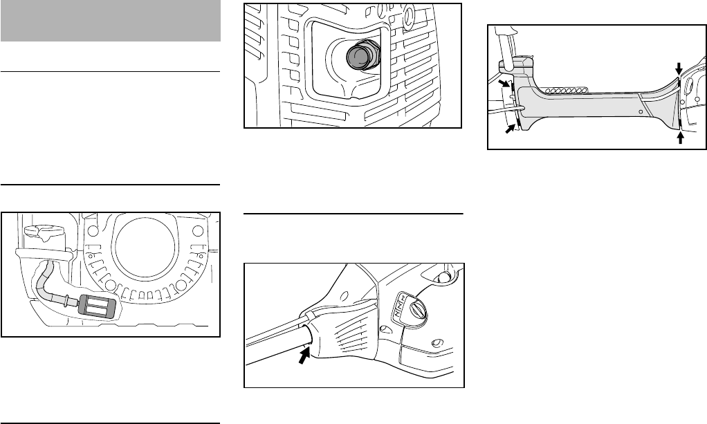
FS 260 C, FS 360 C
English
39
Maintenance Work
STIHL recommends that you have
servicing and repair work carried out
exclusively by an authorized STIHL
servicing dealer.
Fuel Pickup Body in Tank
NCheck the pickup body in the fuel
tank every year and have it replaced
if necessary.
Spark Arrestor in Muffler
The spark arrestor is not installed in all
markets
NIf the engine is down on power,
have the spark arrestor in the
muffler checked.
Antivibration elements
FS 260 C
A vibration-absorbing rubber element is
installed between the powerhead and
the drive tube. Have it checked if there
are signs of wear or a noticeable
increase in vibration levels.
FS 360 C
Four antivibration elements are installed
between the powerhead and the drive
tube. Have the system checked if there
is a noticeable increase in vibrations.
Inspections and
Maintenance by Dealer
9926BA031 KN
9926BA032 KN
9926BA033 KN
6BA015 KN

FS 260 C, FS 360 C
English
40
Maintenance and Care
The following intervals apply to normal operating conditions only. If your daily work-
ing time is longer or operating conditions are difficult (very dusty work area, etc.),
shorten the specified intervals accordingly.
before starting work
after finishing work or daily
after each refueling stop
weekly
monthly
every 12 months
if problem
if damaged
if required
Complete machine
Visual inspection (condition, leaks) XX
Clean X
Control handle Check operation XX
Air filter
Clean XX
Replace X
Pickup body in fuel tank
Check1) X
Replace1) XXX
Fuel tank Clean XXX
Carburetor
Check idle adjustment – the cutting
attachment must not turn XX
Readjust idle speed X
Spark plug
Readjust electrode gap X
Replace after every 100 operating hours
Cooling inlets
Visual inspection X
Clean X
Spark Arrestor in Muffler
Check1) XX
Clean or replace 1) X
Combustion chamber Decoke after first 139 hours of opera-
tion, then every 150 hours of operation X
All accessible screws and nuts (not adjust-
ing screws) Retighten X
Antivibration elements
Check XXX
Replace1) X

FS 260 C, FS 360 C
English
41
Cutting attachment
Visual inspection XX
Replace X
Check tightness XX
Metal cutting attachment Sharpen XX
Safety labels Replace X
1) STIHL recommends that this work be done by a STIHL servicing dealer
The following intervals apply to normal operating conditions only. If your daily work-
ing time is longer or operating conditions are difficult (very dusty work area, etc.),
shorten the specified intervals accordingly.
before starting work
after finishing work or daily
after each refueling stop
weekly
monthly
every 12 months
if problem
if damaged
if required
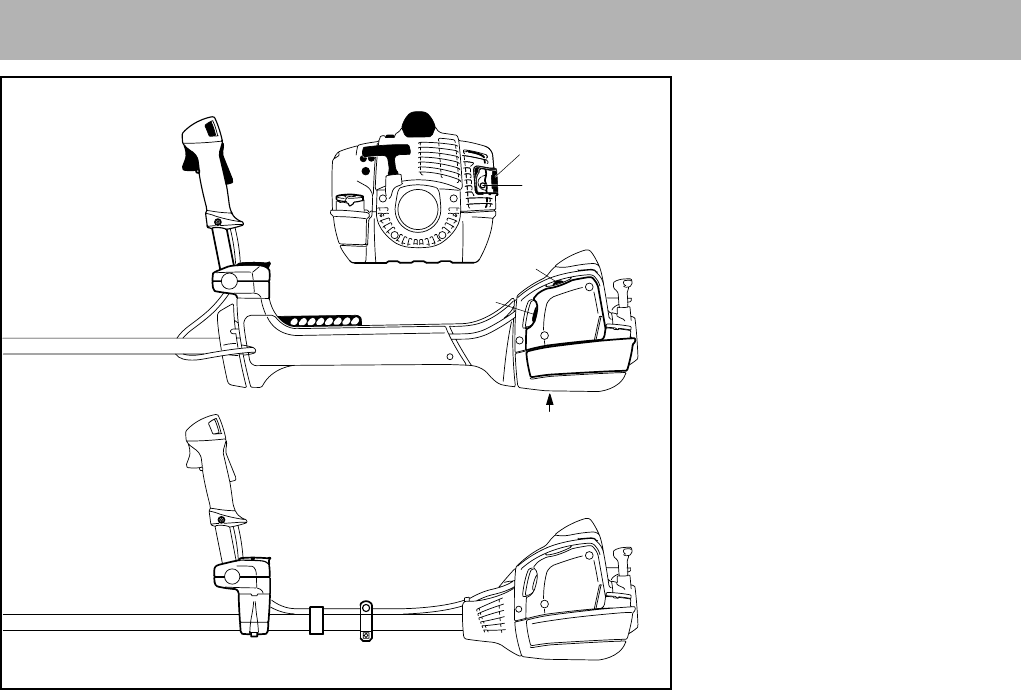
FS 260 C, FS 360 C
English
42
1Fuel Filler Cap
2Carburetor Adjusting Screws
3Starter Grip
4Shutter
5Spark Plug Boot
6Muffler with Spark Arresting Screen
7Spacer
8Guard Plate
9Throttle Trigger
10 Momentary Stop Switch
11 Throttle Trigger Lockout
12 Handlebar
13 Clamp Screw
14 Carrying Strip
15 Choke Lever
16 Fuel Pump
17 Filter Cover
18 Fuel Tank
19 Carrying Ring
20 Throttle Cable Retainer
21 Handle Support
#Serial Number
Main Parts
13
12
20
18
5
4
2
1
15 17
3
9
10
11
14
19
21
6BA017 KN
#
816
21
FS 360
FS 260
7
6
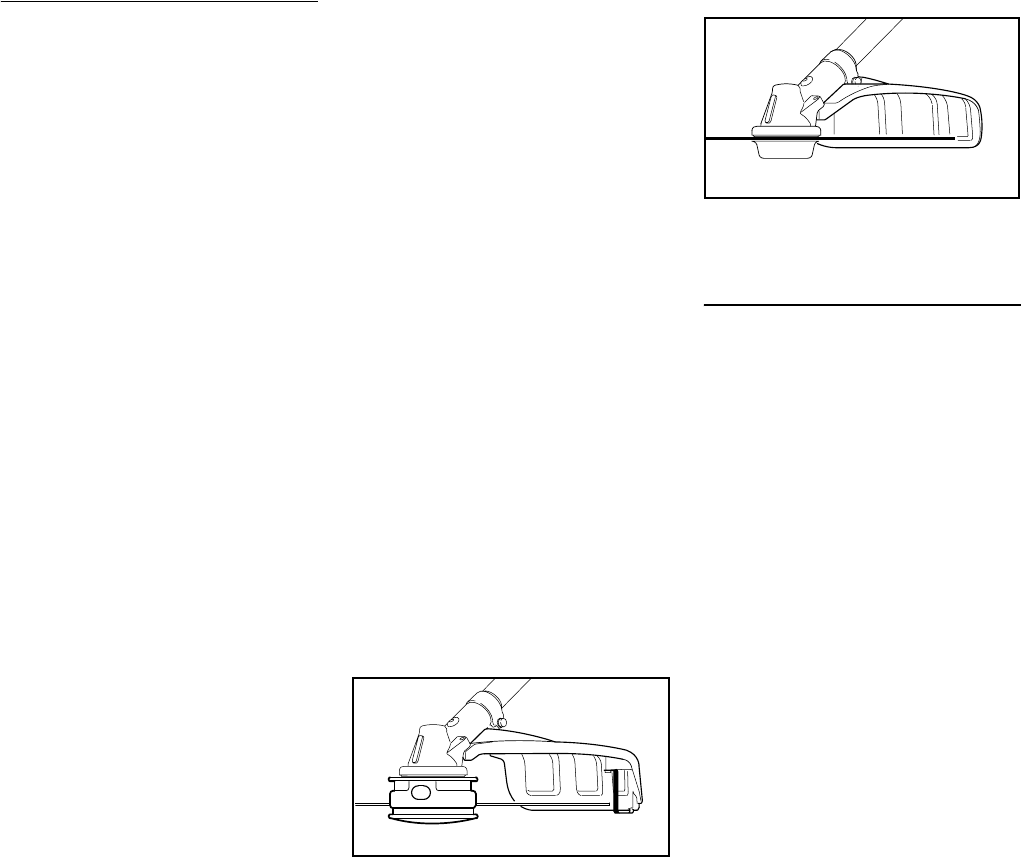
FS 260 C, FS 360 C
English
43
Definitions
1 Fuel Filler Cap
For closing the fuel tank.
2 Carburetor Adjusting Screws
For tuning the carburetor.
3 Starter Grip
The grip of the pull starter, for
starting the engine.
4 Shutter
With summer and winter positions.
Carburetor is heated in winter
position.
5 Spark Plug Boot
Connects the spark plug with the
ignition lead.
6 Muffler with Spark Arresting
Screen
Muffler reduces exhaust noises and
diverts exhaust gases away from
operator.
Spark arresting screen is designed
to reduce the risk of fire.
7Spacer
Designed to reduce the risk of burns
and fire.
8Guard Plate
Protects the fuel tank.
9 Throttle Trigger
Controls the speed of the engine.
10 Momentary Stop Switch
Switches the engine's ignition off
and stops the engine.
11 Throttle Trigger Lockout
Must be depressed before the
throttle trigger can be activated.
12 Handlebar
For holding and controlling the unit
with the hand during operation.
13 Clamp Screw
Locks handlebar in selected
position.
14 Carrying Strip
The device to connect the clearing
saw to the harness.
15 Choke Lever
Eases engine starting by enriching
mixture.
16 Fuel Pump
Provides additional fuel feed for a
cold start.
17 Filter Cover
Encloses and protects the air filter.
18 Fuel Tank
For fuel and oil mixture.
19 Carrying Ring
Connects the unit to the harness.
20 Throttle Cable Retainer
Secures the throttle cable to the
drive tube.
21 Handle Support
Connects the shaft and bike handle.
1Mowing Head
2Deflector for Mowing Heads
3Line Limiting Blade
4Metal Mowing Tool
5Deflector for Metal Mowing Tools
Definitions
1 Mowing Head
The cutting attachment, i. e.
mowing head, for different
purposes.
2 Deflector for Mowing Heads
Designed to reduce the risk of injury
from foreign objects flung
backwards toward the operator by
the cutting attachment and from
contact with the cutting attachment.
3 Line Limiting blade
Metal blade at the deflector in order
to keep the line of the mowing head
at the proper length.
4 Metal Mowing Tool
The cutting attachment, i. e. blade,
made from metal for different
purposes.
5 Deflector for Metal Mowing Tools
Designed to reduce the risk of injury
from foreign objects flung
backwards toward the operator by
the cutting attachment and from
contact with the cutting attachment.
1
002BA412 KN
2
3
002BA417 KN
5
4

FS 260 C, FS 360 C
English
44
6Circular Saw Blade
7Limit Stop for Circular Saw Blade
Definitions
6 Circular Saw Blade
Cutting attachment made of metal
for cutting wood.
7 Limit Stop for Circular Saw Blade
Designed to position the brushcutter
steady against the wood in order to
reduce the risk of injury from loss of
control from reactive forces such as
thrust out.
EPA / CEPA
The Emission Compliance Period
referred to on the Emissions
Compliance Label indicates the number
of operating hours for which the engine
has been shown to meet Federal
emission requirements.
Category
CARB
The Emission Compliance Period used
on the CARB-Air Index Label indicates
the terms:
Engine
Single cylinder two-stroke engine
FS 260 C
FS 360 C
Ignition system
Electronic magneto ignition
7
002BA435 KN
6
Specifications
A = 300 hours
B = 125 hours
C = 50 hours
Extended = 300 hours
Intermediate = 125 hours
Moderate = 50 hours
Displacement: 2.54 cu.in
(41.6 cm3)
Bore: 1.65 in (42 mm)
Stroke: 1.18 in (30 mm)
Engine power to
ISO 8893:
2.7 bhp (2.0 kW)
at 9000 rpm
Idle speed: 2800 rpm
Cut-off speed (nom-
inal value): 12500 rpm
Max. output shaft
speed (cutting
attachment): 8590 rpm
Displacement: 2.30 cu.in
(37.7 cm3)
Bore: 1.57 in (40 mm)
Stroke: 1.18 in (30 mm)
Engine power to
ISO 8893:
2.3 bhp (1.7 kW)
at 8500 rpm
Idle speed: 2800 rpm
Cut-off speed (nom-
inal value): 12500 rpm
Max. output shaft
speed (cutting
attachment): 8590 rpm
Spark plug
(suppressed): NGK CMR6H
Electrode gap: 0.02 in (0.5 mm)

FS 260 C, FS 360 C
English
45
Fuel system
All position diaphragm carburetor with
integral fuel pump
Weight
Overall length
Contact your STIHL dealer for
information regarding special
accessories that may be available for
your product.
Users of this unit should carry out only
the maintenance operations described
in this manual. Other repair work may be
performed only by authorized STIHL
service shops.
Warranty claims following repairs can be
accepted only if the repair has been
performed by an authorized STIHL
servicing dealer using original STIHL
replacement parts.
Original STIHL parts can be identified by
the STIHL part number, the {
logo and, in some cases, by the STIHL
parts symbol K. The symbol may
appear alone on small parts.
Fuel tank capacity:
FS260C: 25.4fl.oz (0.75l)
FS360C: 25.4fl.oz (0.75l)
dry, without cutting attachment and
deflector
FS260C: 17.4lb (7.9kg)
FS360C: 18.7lb (8.5kg)
Without cutting attachment
FS 260 C: 66.34 in (1685 mm)
FS 360 C: 70.47 in (1790 mm)
Special Accessories Maintenance and Repairs

FS 260 C, FS 360 C
English
46
Allocation of STIHL Incorporated
warranty declarations on compliance
with emission requirements for the
following models:
STIHL Incorporated Federal Emission
Control Warranty Statement
–FS 260
Your Warranty Rights and
Obligations
The U.S. Environmental Protection
Agency (EPA) and STIHL Incorporated
are pleased to explain the Emission
Control System Warranty on your
equipment type engine. In the U.S. new
1997 and later model year small off-road
equipment engines must be designed,
built and equipped, at the time of sale, to
meet the U.S. EPA regulations for small
non road engines. The equipment
engine must be free from defects in
materials and workmanship which
cause it to fail to conform with U.S. EPA
standards for the first two years of
engine use from the date of sale to the
ultimate purchaser.
STIHL Incorporated must warrant the
emission control system on your small
off-road engine for the period of time
listed below provided there has been no
abuse, neglect or improper maintenance
of your small off-road equipment engine.
Your emission control system includes
parts such as the carburetor and the
ignition system. Also included may be
hoses, and connectors and other
emission-related assemblies.
Where a warrantable condition exists,
STIHL Incorporated will repair your
small off-road equipment engine at no
cost to you including diagnosis (if the
diagnostic work is performed at an
authorized dealer), parts and labor.
Manufacturer's Warranty Coverage
In the U.S., 1997 and later model year
small off-road equipment engines are
warranted for two years. If any emission-
related part on your engine is defective,
the part will be repaired or replaced by
STIHL Incorporated free of charge.
Owner's Warranty Responsibilities
As the small off-road equipment engine
owner, you are responsible for the
performance of the required
maintenance listed in your instruction
manual. STIHL Incorporated
recommends that you retain all receipts
covering maintenance on your small off-
road equipment engine, but STIHL
Incorporated cannot deny warranty
solely for the lack of receipts or for your
failure to ensure the performance of all
scheduled maintenance.
Any replacement part or service that is
equivalent in performance and durability
may be used in non-warranty
maintenance or repairs, and shall not
reduce the warranty obligations of the
engine manufacturer.
As the small off-road equipment engine
owner, you should be aware, however,
that STIHL Incorporated may deny you
warranty coverage if your small off-road
equipment engine or a part has failed
due to abuse, neglect, improper
maintenance or unapproved
modifications.
You are responsible for presenting your
small off-road equipment engine to a
STIHL service center as soon as a
Allocation of STIHL
Incorporated Warranty
Declarations
STIHL Incorporated
Federal Emission Control
Warranty Statement

FS 260 C, FS 360 C
English
47
problem exists. The warranty repairs will
be completed in a reasonable amount of
time, not to exceed 30 days.
If you have any questions regarding your
warranty rights and responsibilities,
please contact a STIHL customer
service representative at 1-800-467-
8445 or you can write to
STIHL Inc.,
536 Viking Drive, P.O. Box 2015,
Virginia Beach, VA 23450-2015
www.stihlusa.com
Coverage by STIHL Incorporated
STIHL Incorporated warrants to the
ultimate purchaser and each
subsequent purchaser that your small
off-road equipment engine will be
designed, built and equipped, at the time
of sale, to meet all applicable
regulations. STIHL Incorporated also
warrants to the initial purchaser and
each subsequent purchaser that your
engine is free from defects in materials
and workmanship which cause the
engine to fail to conform with applicable
regulations for a period of two years.
Warranty Period
The warranty period will begin on the
date the utility equipment engine is
purchased by the initial purchaser and
you have signed and sent back the
warranty card to STIHL.
If any emission-related part on your
engine is defective, the part will be
replaced by STIHL Incorporated at no
cost to the owner. Any warranted part
which is not scheduled for replacement
as required maintenance, or which is
scheduled only for regular inspection to
the effect of "repair or replace as
necessary" will be warranted for the
warranty period. Any warranted part
which is scheduled for replacement as
required maintenance will be warranted
for the period of time up to the first
scheduled replacement point for that
part.
Diagnosis
You, as the owner, shall not be charged
for diagnostic labor which leads to the
determination that a warranted part is
defective. However, if you claim
warranty for a component and the
machine is tested as non-defective,
STIHL Incorporated will charge you for
the cost of the emission test. Mechanical
diagnostic work will be performed at an
authorized STIHL servicing dealer.
Emission test may be performed either
at STIHL Incorporated or at any
independent test laboratory.
Warranty Work
STIHL Incorporated shall remedy
warranty defects at any authorized
STIHL servicing dealer or warranty
station. Any such work shall be free of
charge to the owner if it is determined
that a warranted part is defective.
Any manufacturer-approved or
equivalent replacement part may be
used for any warranty maintenance or
repairs on emission-related parts and
must be provided without charge to the
owner. STIHL Incorporated is liable for
damages to other engine components
caused by the failure of a warranted part
still under warranty.
The following list specifically defines the
emission-related warranted parts:
–Air Filter
–Carburetor
–Fuel Pump
–Choke (Cold Start Enrichment
System)
–Control Linkages
–Intake Manifold
–Magneto or Electronic Ignition
System (Ignition Module)
–Spark Plug
–Catalytic Converter (if applicable)
–Fuel Tank
–Fuel Cap
–Fuel Line
–Fuel Line Fittings
–Clamps
–Fasteners
Where to make a Claim for Warranty
Service
Bring the product to any authorized
STIHL servicing dealer and present the
signed warranty card.
Maintenance Requirements
The maintenance instructions in this
manual are based on the application of
the recommended 2-stroke fuel-oil

FS 260 C, FS 360 C
English
48
mixture (see also instruction "Fuel").
Deviations from this recommendation
regarding quality and mixing ratio of fuel
and oil may require shorter maintenance
intervals.
Limitations
This Emission Control Systems
Warranty shall not cover any of the
following:
Nrepair or replacement required
because of misuse, neglect or lack
of required maintenance,
Nrepairs improperly performed or
replacements not conforming to
STIHL Incorporated specifications
that adversely affect performance
and/or durability, and alterations or
modifications not recommended or
approved in writing by STIHL
Incorporated,
and
Nreplacement of parts and other
services and adjustments
necessary for required maintenance
at and after the first scheduled
replacement point.
Allocation of STIHL Incorporated
warranty declarations on compliance
with emission requirements for the
following models:
STIHL Incorporated Federal Emission
Control Warranty Statement
–FS 360
STIHL Incorporated California Exhaust
and Evaporative Emissions Control
Warranty Statement
–FS 360
Not for California
Your Warranty Rights and
Obligations
The U.S. Environmental Protection
Agency (EPA) and STIHL Incorporated
are pleased to explain the Emission
Control System Warranty on your
equipment type engine. In the U.S. new
1997 and later model year small off-road
equipment engines must be designed,
built and equipped, at the time of sale, to
meet the U.S. EPA regulations for small
non road engines. The equipment
engine must be free from defects in
materials and workmanship which
cause it to fail to conform with U.S. EPA
standards for the first two years of
engine use from the date of sale to the
ultimate purchaser.
STIHL Incorporated must warrant the
emission control system on your small
off-road engine for the period of time
listed below provided there has been no
abuse, neglect or improper maintenance
of your small off-road equipment engine.
Your emission control system includes
parts such as the carburetor and the
ignition system. Also included may be
hoses, and connectors and other
emission-related assemblies.
Where a warrantable condition exists,
STIHL Incorporated will repair your
small off-road equipment engine at no
Allocation of STIHL
Incorporated Warranty
Declarations
STIHL Incorporated
Federal Emission Control
Warranty Statement
FS 260 C, FS 360 C
English
49
cost to you, including diagnosis (if the
diagnostic work is performed at an
authorized dealer), parts, and labor.
Manufacturer's Warranty Coverage
In the U.S., 1997 and later model year
small off-road equipment engines are
warranted for two years. If any emission-
related part on your engine is defective,
the part will be repaired or replaced by
STIHL Incorporated free of charge.
Owner's Warranty Responsibilities
As the small off-road equipment engine
owner, you are responsible for the
performance of the required
maintenance listed in your instruction
manual. STIHL Incorporated
recommends that you retain all receipts
covering maintenance on your small off-
road equipment engine, but STIHL
Incorporated cannot deny warranty
solely for the lack of receipts or for your
failure to ensure the performance of all
scheduled maintenance.
Any replacement part or service that is
equivalent in performance and durability
may be used in non-warranty
maintenance or repairs, and shall not
reduce the warranty obligations of the
engine manufacturer.
As the small off-road equipment engine
owner, you should be aware, however,
that STIHL Incorporated may deny you
warranty coverage if your small off-road
equipment engine or a part has failed
due to abuse, neglect, improper
maintenance or unapproved
modifications.
You are responsible for presenting your
small off-road equipment engine to a
STIHL service center as soon as a
problem exists. The warranty repairs will
be completed in a reasonable amount of
time, not to exceed 30 days.
If you have any questions regarding your
warranty rights and responsibilities,
please contact a STIHL customer
service representative at 1-800-467-
8445 or you can write to
STIHL Inc.,
536 Viking Drive, P.O. Box 2015,
Virginia Beach, VA 23450-2015
www.stihlusa.com
Coverage by STIHL Incorporated
STIHL Incorporated warrants to the
ultimate purchaser and each
subsequent purchaser that your small
off-road equipment engine will be
designed, built and equipped, at the time
of sale, to meet all applicable
regulations. STIHL Incorporated also
warrants to the initial purchaser and
each subsequent purchaser that your
engine is free from defects in materials
and workmanship which cause the
engine to fail to conform with applicable
regulations for a period of two years.
Warranty Period
The warranty period will begin on the
date the utility equipment engine is
purchased by the initial purchaser and
you have signed and sent back the
warranty card to STIHL.
If any emission-related part on your
engine is defective, the part will be
replaced by STIHL Incorporated at no
cost to the owner. Any warranted part
which is not scheduled for replacement
as required maintenance, or which is
scheduled only for regular inspection to
the effect of "repair or replace as
necessary" will be warranted for the
warranty period. Any warranted part
which is scheduled for replacement as
required maintenance will be warranted
for the period of time up to the first
scheduled replacement point for that
part.
Diagnosis
You, as the owner, shall not be charged
for diagnostic labor which leads to the
determination that a warranted part is
defective. However, if you claim
warranty for a component and the
machine is tested as non-defective,
STIHL Incorporated will charge you for
the cost of the emission test. Mechanical
diagnostic work will be performed at an
authorized STIHL servicing dealer.
Emission test may be performed either
at STIHL Incorporated or at any
independent test laboratory.
Warranty Work
STIHL Incorporated shall remedy
warranty defects at any authorized
STIHL servicing dealer or warranty
station. Any such work shall be free of
charge to the owner if it is determined
that a warranted part is defective.
Any manufacturer-approved or
equivalent replacement part may be
used for any warranty maintenance or
repairs on emission-related parts and
must be provided without charge to the
owner. STIHL Incorporated is liable for
damages to other engine components
caused by the failure of a warranted part
still under warranty.
The following list specifically defines the
emission-related warranted parts:

FS 260 C, FS 360 C
English
50
–Air Filter
–Carburetor
–Fuel Pump
–Choke (Cold Start Enrichment
System)
–Control Linkages
–Intake Manifold
–Magneto or Electronic Ignition
System (Ignition Module)
–Spark Plug
–Catalytic Converter (if applicable)
–Fuel Tank
–Fuel Cap
–Fuel Line
–Fuel Line Fittings
–Clamps
–Fasteners
Where to make a Claim for Warranty
Service
Bring the product to any authorized
STIHL servicing dealer and present the
signed warranty card.
Maintenance Requirements
The maintenance instructions in this
manual are based on the application of
the recommended 2-stroke fuel-oil
mixture (see also instruction "Fuel").
Deviations from this recommendation
regarding quality and mixing ratio of fuel
and oil may require shorter maintenance
intervals.
Limitations
This Emission Control Systems
Warranty shall not cover any of the
following:
Nrepair or replacement required
because of misuse, neglect or lack
of required maintenance,
Nrepairs improperly performed or
replacements not conforming to
STIHL Incorporated specifications
that adversely affect performance
and/or durability, and alterations or
modifications not recommended or
approved in writing by STIHL
Incorporated,
and
Nreplacement of parts and other
services and adjustments
necessary for required maintenance
at and after the first scheduled
replacement point.
For California only
Your Warranty Rights and
Obligations
The California Air Resources Board
(CARB) and STIHL Incorporated are
pleased to explain the Emission Control
System Warranty on your 2007 and later
small off-road equipment engine.
In California, new equipment that uses
small off-road engines must be
designed, built, and equipped to meet
the State's stringent anti-smog
standards. STIHL Incorporated must
warrant the emissions control system on
your small off-road engine for the period
listed below provided there has been no
abuse, neglect or improper maintenance
of your small off-road engine.
Your emissions control system may
include parts such as:
Air Filter, Carburetor, Fuel Pump, Choke
(Cold Start Enrichment System), Control
Linkages, Intake Manifold, Magneto or
Electronic Ignition System (Ignition
Module), Spark Plug, Catalytic
Converter (if applicable), Fuel Tank,
Fuel Cap, Fuel Line, Fuel Line Fittings,
Clamps, Fasteners.
STIHL Incorporated
California Exhaust and
Evaporative Emissions
Control Warranty
Statement
FS 260 C, FS 360 C
English
51
Where a warrantable condition exists,
STIHL Incorporated will repair your
small off-road equipment engine at no
cost to you including diagnosis, parts
and labor.
Manufacturer’s Warranty
Responsibilities
This emissions control system is
warranted for two years in California. If
any emissions-related part on your
equipment is defective, the part will be
repaired or replaced by STIHL
Incorporated free of charge.
Owner’s Warranty Responsibilities
As the small off-road equipment engine
owner, you are responsible for
performance of the required
maintenance listed in your instruction
manual. STIHL Incorporated
recommends that you retain all receipts
covering maintenance on your small off-
road equipment engine, but STIHL
Incorporated cannot deny warranty
solely for the lack of receipts or your
failure to ensure the performance of all
scheduled maintenance.
As the small off-road equipment engine
owner, you should however be aware
that STIHL Incorporated may deny you
warranty coverage if your small off-road
equipment engine or a part has failed
due to abuse, neglect, or improper
maintenance or unapproved
modifications.
You are responsible for presenting your
small off-road equipment engine to a
STIHL servicing dealer as soon as the
problem exists. The warranty repairs
should be completed in a reasonable
amount of time, not to exceed 30 days. If
you have any questions regarding your
warranty rights and responsibilities,
please contact a STIHL customer
service representative at 1-800-467-
8445 or you can write to
STIHL Inc., 536 Viking Drive,
P.O. Box 2015,
Virginia Beach, VA 23450-2015.
Coverage by STIHL Incorporated
STIHL Incorporated warrants to the
ultimate purchaser and each
subsequent purchaser that your small
off-road equipment engine is designed,
built and equipped, at the time of sale, to
meet all applicable emission
regulations.
STIHL Incorporated also warrants to the
initial purchaser and each subsequent
purchaser that your engine is free from
defects in materials and workmanship
which cause the engine to fail to conform
to applicable emission regulations for a
period of two years.
Defects Warranty Period
The warranty periods will begin on the
date the utility equipment engine is
purchased by the initial purchaser. If any
emission-related part on your engine is
defective, the part will be replaced by
STIHL Incorporated at no cost to the
owner.
Add-on or modified parts that are not
exempted by CARB may not be used.
The use of any non exempted add-on or
modified parts will be grounds for
disallowing a warranty claim. STIHL
Incorporated will not be liable to warrant
failures of warranted parts caused by the
use of a non exempted add-on or
modified part.
The warranty on emissions-related parts
will be interpreted as follows:
1. Any warranted part that is not
scheduled for replacement as
required maintenance in the written
instructions required in the
Emission Warranty Parts List (see
below) must be warranted for the
warranty period defined in
Subsection COVERAGE BY STIHL
INCORPORATED, see above. If
any such part fails during the period
of warranty coverage, it must be
repaired or replaced by the
manufacturer according to
Subsection (4) below. Any such part
repaired or replaced under the
warranty must be warranted for the
remaining warranty period.
2. Any warranted part that is
scheduled only for regular
inspection in the written instructions
required by the Emission Warranty
Parts List (see below) must be
warranted for the warranty period
defined in Subsection COVERAGE
BY STIHL INCORPORATED, see
above. A statement in such written
instructions to the effect of "repair or
replace as necessary" will not
reduce the period of warranty
coverage. Any such part repaired or
replaced under warranty must be
warranted for the remaining
warranty period.
3. Any warranted part that is
scheduled for replacement as
required maintenance in the written
instructions required by the
Emission Warranty Parts List (see
below) must be warranted for the
period of time prior to the first
scheduled replacement point for

FS 260 C, FS 360 C
English
52
that part. If the part fails prior to the
first scheduled replacement, the
part must be repaired or replaced by
the engine manufacturer according
to Subsection (4) below. Any such
part repaired or replaced under
warranty must be warranted for the
remainder of the period prior to the
first scheduled replacement point
for the part.
4. Repair or replacement of any
warranted part under the warranty
must be performed at a warranty
station at no charge to the owner.
5. Notwithstanding the provisions of
Subsection (4) above, warranty
services or repairs will be provided
at all manufacturer distribution
centers that are authorized to
service the subject engines.
6. The owner must not be charged for
diagnostic labor that leads to the
determination that a warranted part
is in fact defective, provided that
such diagnostic work is performed
at a warranty station.
Warranty Work
STIHL Incorporated shall remedy
warranty defects at any authorized
STIHL servicing dealer or warranty
station. Any such work shall be free of
charge to the owner if it is determined
that a warranted part is defective. Any
manufacturer approved or equivalent
replacement part may be used for any
warranty maintenance or repairs on
emission-related parts and must be
provided without charge to the owner.
STIHL Incorporated is liable for
damages to other engine components
caused by the failure of a warranted part
still under warranty.
Emission Warranty Parts List
Air Filter, Carburetor, Fuel Pump, Choke
(Cold Start Enrichment System), Control
Linkages, Intake Manifold, Magneto or
Electronic Ignition System (Ignition
Module), Spark Plug, Catalytic
Converter (if applicable), Fuel Tank,
Fuel Cap, Fuel Line, Fuel Line Fittings,
Clamps, Fasteners
Where to make a Claim for Warranty
Service
Bring the STIHL product to any
authorized STIHL servicing dealer and
present the signed STIHL product
registration card, or the print-out of the
electronic product registration.
Limitations
The repair or replacement of any
warranted part otherwise eligible for
warranty coverage may be excluded
from such warranty coverage if STIHL
Incorporated demonstrates that the
STIHL product has been abused,
neglected, or improperly maintained,
and that such abuse, neglect, or
improper maintenance was the direct
cause of the need for repair or
replacement of the part. That
notwithstanding, any adjustment of a
component that has a factory installed,
and properly operating, adjustment
limiting device is still eligible for warranty
coverage.
STIHL Registered Trademarks
STIHL®
{
K
The color combination orange-grey
(U.S. Registrations #2,821,860;
#3,010,057, #3,010,058, #3,400,477;
and #3,400,476)
4-MIX®
AUTOCUT®
EASYSTART®
FARM BOSS®
OILOMATIC®
STIHL Cutquik®
STIHL DUROMATIC®
STIHL Quickstop®
STIHL ROLLOMATIC®
STIHL WOOD BOSS®
TIMBERSPORTS®
YARD BOSS®
Some of STIHL’s Common Law
Trademarks
Trademarks
FS 260 C, FS 360 C
English
53
BioPlus™
Easy2Start™
EasySpool™
ElastoStart™
Ematic™ / Stihl-E-Matic™
FixCut™
HT Plus™
IntelliCarb™
Master Control Lever™
Micro™
Pro Mark™
Quad Power™
Quiet Line™
STIHL M-Tronic™
STIHL Compact™
STIHL HomeScaper Series™
STIHL Interchangeable Attachment
Series™
STIHL Magnum™ / Stihl-Magnum™
STIHL MiniBoss™
STIHL MotoPlus 4™
STIHL Multi-Cut HomeScaper Series™
STIHL OUTFITTERS™
STIHL PICCO™
STIHL PolyCut™
STIHL PowerSweep™
STIHL Precision Series™
STIHL Protech™
STIHL RAPID™
STIHL SuperCut™
STIHL Territory™
TapAction™
TrimCut™
This listing of trademarks is subject to
change.
Any unauthorized use of these
trademarks without the express written
consent of
ANDREAS STIHL AG & Co. KG,
Waiblingen is strictly prohibited.
FS 260 C, FS 360 C
English
54

Manual de instrucciones originalImpreso en papel libre de cloro.
Las tintas contienen aceites vegetales, el papel es reciclable.
© ANDREAS STIHL AG & Co. KG, 2010
0458-743-8621-A. M0-21.J10.DDS.
0000003973_002_EA
FS 260 C, FS 360 C
español / EE.UU
55
{
Contenido
Permita que solamente las personas
que comprenden la materia tratada en
este manual manejen su
orilladora/cortadora de matorrales.
Para obtener el rendimiento y
satisfacción máximos de la
orilladora/cortadora de matorrales
STIHL, es importante que lea, obedezca
y comprenda las precauciones de
seguridad y las instrucciones de uso y
mantenimiento dadas en el capítulo
"Precauciones de seguridad y técnicas
de uso", antes de usar la orilladora. Para
obtener información adicional, visite
www.stihlusa.com.
Comuníquese con su representante de
STIHL o el distribuidor de STIHL para su
zona si no se entiende alguna de las
instrucciones dadas en el presente
manual.
Asegúrese que su máquina esté
equipada con el deflector, mango y
arnés adecuados para el tipo de
accesorio de corte que se está
utilizando. Siempre protéjase
adecuadamente los ojos.
Acerca de este manual de
instrucciones 56
Medidas de seguridad y técnicas
de manejo 57
Combinaciones aprobadas de
accesorio de corte, deflector, tope
limitador y arnés 72
Montaje del manillar 73
Montaje de la barra de defensa 76
Montaje del accesorio de corte 77
Combustible 80
Llenado de combustible 81
Colocación del arnés completo 84
Equilibro de la unidad 84
Arranque / parada del motor 86
Instrucciones para el uso 88
Limpieza del filtro de aire 89
Gestión del motor 89
Ajuste del carburador 90
Manejo durante el invierno 90
Bujía 92
Funcionamiento del motor 93
Sustitución de la cuerda de
arranque y del resorte de
rebobinado 94
Almacenamiento de la máquina 96
Afilado de los accesorios de corte 96
Inspección y mantenimiento por el
usuario 97
Inspección y mantenimiento por el
concesionario 97
Información para mantenimiento 99
Componentes importantes 101
Especificaciones 103
Accesorios especiales 104
Información de reparación 105
Asignación de declaraciones de
garantía de STIHL Incorporated 105
Declaración de garantía de STIHL
Incorporated sobre sistemas de
control de emisiones según normas
Federales 105
Asignación de declaraciones de
garantía de STIHL Incorporated 108
Declaración de garantía de STIHL
Incorporated sobre sistemas de
control de emisiones según normas
Federales 108
Declaración de garantía de STIHL
Incorporated sobre el control de
emisiones de gases de escape y
emisiones por evaporación para el
Estado de California 110
Marcas comerciales 113 Advertencia!
Dado que la orilladora/cortadora de
matorrales es una herramienta de corte
motorizada de gran velocidad, es nece-
sario tomar medidas especiales de
seguridad para reducir el riesgo de
lesiones. El uso descuidado o inade-
cuado puede causar lesiones graves e
incluso mortales.
FS 260 C, FS 360 C
español / EE.UU
56
Pictogramas
Todos los pictogramas que se
encuentran fijados o grabados en la
máquina se explican en este manual.
Según el modelo, los pictogramas
siguientes pueden aparecer en su
máquina.
Símbolos en el texto
Muchas de las instrucciones de uso y
seguridad vienen acompañadas de
ilustraciones.
Los pasos individuales o
procedimientos descritos en el manual
pueden estar señalados en diferentes
maneras:
NSe usa un punto para denotar un
paso o procedimiento.
Una descripción de un paso o
procedimiento que se refiere
directamente a una ilustración puede
contener números de referencia que
aparecen en la ilustración. Ejemplo:
NSuelte el tornillo (1).
NPalanca (2) ...
Además de las instrucciones de uso, en
este manual pueden encontrarse
párrafos a los que usted debe prestar
atención especial. Tales párrafos están
marcados con los símbolos y las
palabras identificadoras que se
describen a continuación.
Mejoramientos técnicos
La filosofía de STIHL es mejorar
continuamente todos sus productos.
Como resultado de ello, periódicamente
se introducen cambios de diseño y
mejoras. Por lo tanto, es posible que
algunos cambios, modificaciones y
mejoras no se describen en este
manual. Si las características de
funcionamiento o la apariencia de su
máquina difieren de las descritas en
este manual, comuníquese con el
concesionario STIHL para obtener la
ayuda que requiera.
Acerca de este manual de
instrucciones
Tanque de combustible
que contiene la mezcla
de combustible y aceite
Presione para accionar la
válvula de
descompresión
Bomba de combustible
manual
Presione para accionar la
bomba manual de
combustible
Orificio de llenado para
lubricante de engranajes
Toma de aire para modo
de verano
Toma de aire para modo
de invierno
Calentador de manillar
¡Peligro!
Indica un riesgo inminente de lesiones
graves o mortales.
Advertencia!
Identifica una situación de peligro que,
al no evitarse, puede resultar en lesio-
nes graves o mortales.
¡Precaución!
Indica el riesgo de daños a la propie-
dad, incluyendo a la máquina o sus
componentes.

FS 260 C, FS 360 C
español / EE.UU
57
Los términos empleados en este manual
para designar la herramienta
motorizada variarán de acuerdo con los
tipos de accesorios de corte instalados
en la misma. La palabra "orilladora" se
usa para identificar una unidad FS
equipada con un cabezal de hilo de nilón
o un cabezal con cuchillas de plástico
flexibles (tal como el cabezal PolyCut).
La designación "cortadora de
matorrales" identifica una unidad
equipada con una cuchilla de metal
rígida. Muchos de los modelos FS
pueden usarse como una orilladora o
una cortadora de matorrales – por lo
tanto, la herramienta motorizada se
designa aquí como una "orilladora /
cortadora de matorrales". Algunos de
los modelos FS pequeños y/o livianos
sólo pueden usarse como orilladoras, es
decir no pueden equiparse con cuchillas
metálicas.
El término "sierra despejadora"
identifica una orilladora / cortadora de
matorrales de alta potencia
particularmente útil para usar con una
sierra circular para cortar árboles
jóvenes o pequeños.
Pida a su concesionario STIHL que le
enseñe el manejo de la herramienta
motorizada. Respete todas las
disposiciones, reglamentos y normas de
seguridad locales del caso.
Use la sierra despejadora equipada con
el accesorio de corte apropiado
únicamente para cortar pasto,
matorrales, madera y materiales
similares.
Medidas de seguridad y
técnicas de manejo
Dado que la sierra des-
pejadora es una
herramienta de corte
motorizada, con cuchi-
llas afiladas, que
funciona a gran veloci-
dad, es necesario tomar
medidas especiales de
seguridad para reducir el
riesgo de lesiones.
Es importante que usted
lea, comprenda bien y
respete las siguientes
advertencias y medidas
de seguridad. Lea el
manual de instrucciones
y las precauciones de
seguridad periódica-
mente. El uso
descuidado o inadecuado
puede causar lesiones
graves o incluso
mortales.
Advertencia!
Tal como se explicará a continuación en
estas Medidas de seguridad, para redu-
cir el riesgo de lesiones personales,
asegúrese que su máquina esté equi-
pada con el deflector, tope limitador y
arnés adecuados para el tipo de acce-
sorio de corte que se está utilizando.
Utilice exclusivamente los accesorios
de corte autorizados específicamente
por STIHL para usar en su modelo FS.
Advertencia!
No preste ni alquile nunca su herra-
mienta motorizada sin entregar el
manual de instrucciones. Asegúrese
que todas las personas que utilicen la
máquina lean y comprendan la informa-
ción contenida en este manual.
Advertencia!
El uso de esta máquina puede ser peli-
groso. Si el hilo o la cuchilla giratoria
llega a entrar en contacto con su
cuerpo, le ocasionará una cortadura.
Cuando choca con algún objeto extraño
sólido tal como rocas o pedazos de
metal, puede arrojarlo directamente o
por rebote en dirección de personas
que se encuentren en la cercanía o del
operador. El contacto con dichos obje-
tos puede dañar los accesorios de corte
y puede hacer que las cuchillas se rom-
pan, astillen o agrieten. Los objetos
lanzados, incluso los cabezales o las
cuchillas rotos, pueden provocar lesio-
nes graves o mortales al operador o a
personas que se encuentren en su
proximidad. STIHL no recomienda el
uso de cuchillas rígidas en zonas
pedregosas.
Advertencia!
No debe usarse para ningún otro propó-
sito ya que el uso indebido puede
resultar en lesiones personales o daños
a la propiedad, incluso daños de la
máquina.
Advertencia!
Nunca se debe permitir a los niños que
usen esta herramienta motorizada. No
se debe permitir la proximidad de otros,
especialmente niños y animales, donde
se esté utilizando la máquina.

FS 260 C, FS 360 C
español / EE.UU
58
La mayoría de las medidas de seguridad
y avisos contenidos en este manual se
refieren al uso de todas las sierras
despejadoras de STIHL. Los distintos
modelos pueden contar con piezas y
controles diferentes. Vea la sección
correspondiente de su manual de
instrucciones para tener una
descripción de los controles y la función
de los componentes de su modelo.
El uso seguro de una sierra despejadora
atañe a
1. el operador
2. la herramienta motorizada
3. el uso de la herramienta
motorizada.
EL OPERADOR
Condición física
Usted debe estar en buenas
condiciones físicas y psíquicas y no
encontrarse bajo la influencia de
ninguna sustancia (drogas, alcohol,
etc.) que le pueda restar visibilidad,
destreza o juicio. No maneje esta
máquina cuando está fatigado.
Estas condiciones reducen la capacidad
de las manos de sentir y regular la
temperatura, producen entumecimiento
y ardor y pueden provocar trastornos
nerviosos y circulatorios, así como
necrosis de los tejidos.
No se conocen todos los factores que
contribuyen a la enfermedad de
Raynaud, pero el clima frío, el fumar y
las enfermedades o condiciones físicas
que afectan los vasos sanguíneos y la
circulación de la sangre, como asimismo
los niveles altos de vibración y períodos
prolongados de exposición a la
vibración son mencionados como
factores en el desarrollo de la
enfermedad de Raynaud. Por lo tanto,
para reducir el riesgo de la enfermedad
de dedos blancos y del síndrome del
túnel carpiano, sírvase notar lo
siguiente:
–La mayor parte de las herramientas
motorizadas de STIHL se ofrecen
con un sistema antivibración ("AV")
cuyo propósito es reducir la
transmisión de las vibraciones
creadas por la máquina a las manos
del operador. Se recomienda el uso
del sistema AV a aquellas personas
que utilizan herramientas
motorizadas en forma constante y
regular.
–Use guantes y mantenga las manos
abrigadas.
–Mantenga el sistema AV en buen
estado. Una herramienta
motorizada con los componentes
flojos o con elementos AV dañados
o desgastados también tendrá
tendencia a tener niveles más altos
de vibración.
–Agarre firmemente los mangos en
todo momento, pero no los apriete
con fuerza constante y excesiva.
Tómese descansos frecuentes.
Todas las precauciones antes
mencionadas no le garantizan que va a
estar totalmente protegido contra la
enfermedad de Raynaud o el síndrome
del túnel carpiano. Por lo tanto, los
operadores constantes y regulares
deben revisar con frecuencia el estado
de sus manos y dedos. Si aparece
alguno de los síntomas arriba
mencionados, consulte inmediatamente
al médico.
Advertencia!
Para reducir el riesgo de ocasionar
lesiones a las personas en la cercanía y
daños a la propiedad, nunca deje la
herramienta motorizada en marcha
desatendida. Cuando no está en uso
(por ejemplo durante el descanso), apá-
guela y asegúrese de que las personas
no autorizadas no puedan usarla.
Advertencia!
Esté alerta. Si se cansa, tómese un des-
canso. El cansancio puede provocar
una pérdida del control. El uso de cual-
quier herramienta motorizada es
fatigoso. Si usted padece de alguna
dolencia que pueda ser agravada por la
fatiga, consulte a su médico antes de
utilizar esta máquina.
Advertencia!
El uso prolongado de una herramienta
motorizada (u otras máquinas) expone
al operador a vibraciones que pueden
provocar el fenómeno de Raynaud
(dedos blancos) o el síndrome del túnel
carpiano.
FS 260 C, FS 360 C
español / EE.UU
59
Vestimenta adecuada
Para reducir el riesgo de lesiones el
operador debe usar el equipo protector
adecuado.
Esté especialmente alerta y tenga
cuidado cuando se usa protectores de
oídos, ya que los mismos reducen la
posibilidad de oír señales de
advertencia (gritos, alarmas, etc.).
Evite el uso de chaquetas sueltas,
bufandas, corbatas, joyas, pantalones
acampanados o con vueltas, pelo largo
suelto o cualquier cosa que pueda
engancharse en las ramas, matorrales o
piezas en movimiento de la máquina.
Sujétese el pelo de modo que quede
sobre los hombros.
LA HERRAMIENTA MOTORIZADA
Para las ilustraciones y definiciones de
los componentes de la herramienta
motorizada, vea el capítulo sobre
"Piezas principales".
Advertencia!
El sistema de encendido de la máquina
STIHL produce un campo electromag-
nético de intensidad muy baja. El mismo
puede interferir con algunos tipos de
marcapasos. Para reducir el riesgo de
lesiones graves o mortales, las perso-
nas portadoras de marcapasos deben
consultar a sus médicos y al fabricante
del marcapasos antes de usar esta
máquina.
Advertencia!
El deflector provisto con su herramienta
motorizada no siempre protege al ope-
rador contra todos los objetos extraños
(gravilla, vidrio, alambre, etc.) arrojados
por el accesorio de corte giratorio. Los
objetos arrojados o lanzados por el
accesorio también pueden rebotar y
golpear al operador.
Advertencia!
Para reducir el riesgo de
lesionarse los ojos,
nunca maneje la herra-
mienta motorizada si no
tiene puestas gafas o
anteojos de seguridad
bien ajustados con una protección ade-
cuada en las partes superior y laterales
que satisfagan la norma ANSI Z 87.1 (o
la norma nacional correspondiente).
Para reducir el riesgo de lesionarse la
cara, STIHL recomienda usar también
una careta o protector facial adecuado
sobre las gafas o anteojos de
seguridad.
Utilice un casco de seguridad aprobado
para reducir el riesgo de lesionarse la
cabeza en caso de existir tal tipo de
peligro.
El ruido de la herramienta motorizada
puede dañar los oídos. Siempre use
amortiguadores del ruido (tapones u
orejeras) para protegerse los oídos. Los
usuarios constantes y regulares deben
someterse con frecuencia a un examen
o control auditivo.
Siempre use guantes al
usar la máquina y las
cuchillas metálicas. Los
guantes gruesos y anti-
deslizantes mejoran el
manejo y ayudan a prote-
ger las manos.
La ropa debe ser de con-
fección fuerte y ajustada,
pero no tanto que impida
la completa libertad de
movimiento. Use pantalo-
nes largos hechos de un
material grueso para pro-
tegerse las piernas. No
use pantalones cortos,
sandalias o pies
descalzos.
Es muy importante tener
una buena superficie de
apoyo para los pies. Pón-
gase botas gruesas con
suela antideslizante.
Recomendamos las
botas de seguridad con
puntera de acero.
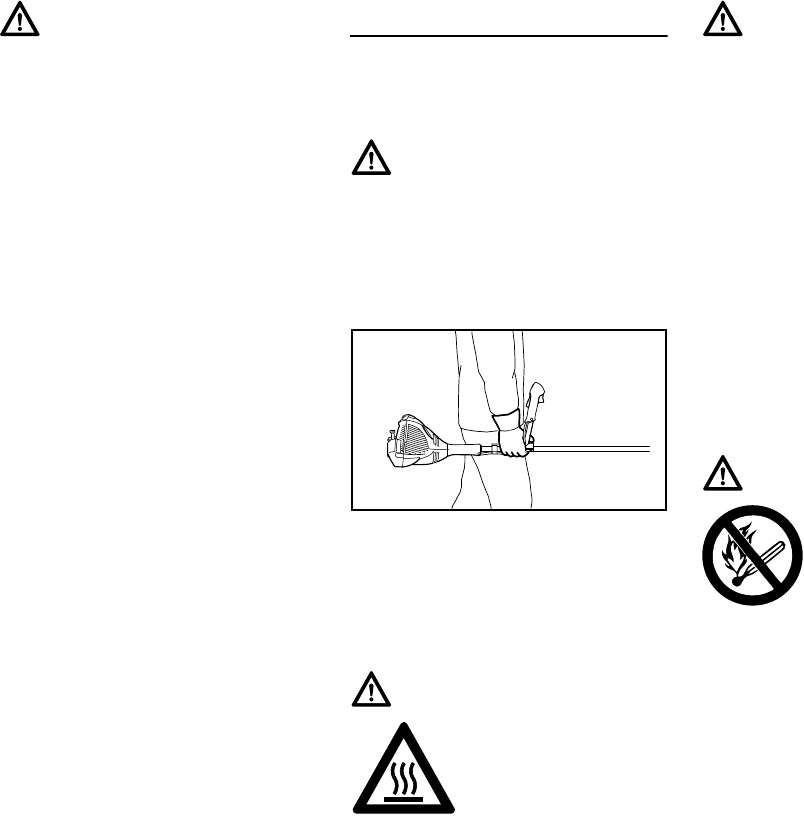
FS 260 C, FS 360 C
español / EE.UU
60
Si la máquina experimenta cargas
excesivas para las cuales no fue
diseñada (por ejemplo, impactos
severos o una caída), siempre
asegúrese de que la máquina esté en
buenas condiciones antes de seguir con
el trabajo. Inspeccione específicamente
la integridad del sistema de combustible
(ausencia de fugas) y asegúrese de que
los controles y dispositivos de seguridad
funcionen como es debido. No siga
manejando esta máquina si está
dañada. En caso de dudas, pida que el
concesionario de servicio de STIHL la
revise.
USO DE LA HERRAMIENTA
MOTORIZADA
Transporte de la herramienta
motorizada
Puede acarrearse solamente en
posición horizontal. Agarre el eje de una
manera que mantenga la máquina
equilibrada horizontalmente. Mantenga
el silenciador caliente lejos de su cuerpo
y el accesorio de corte detrás de usted.
Combustible
La herramienta motorizada STIHL utiliza
una mezcla de aceite-gasolina como
combustible (vea el capítulo
"Combustible" en el manual del
propietario).
Advertencia!
Nunca modifique, de ninguna manera,
esta herramienta motorizada. Utilice
únicamente los accesorios y repuestos
suministrados por STIHL y expresa-
mente autorizados por STIHL para
usarse con el modelo específico de
STIHL. Si bien es posible conectar a la
herramienta motorizada de STIHL cier-
tos accesorios no autorizados, su uso
puede ser, en la práctica, extremada-
mente peligroso. Para los accesorios de
corte autorizados por STIHL para su
unidad, consulte el capítulo "Combina-
ciones aprobadas de accesorio de
corte, deflector, mango y arnés", en el
manual de instrucciones o en el catá-
logo STIHL "Accesorios de corte,
piezas y accesorios".
Advertencia!
Para reducir el riesgo de sufrir lesiones
debido a la pérdida de control y al con-
tacto con las cuchillas o el hilo, nunca
lleve ni transporte la herramienta moto-
rizada con el accesorio de corte en
marcha.
Advertencia!
Para reducir el riesgo de
lesiones por quemadu-
ras, no toque las piezas
de la máquina ni la caja
de engranajes cuando
están calientes.
002BA272 KN
Advertencia!
Antes de apoyar la sierra despejadora
en el suelo, apague el motor y asegú-
rese de que el accesorio de corte ha
dejado de girar. Cuando transporte la
máquina en un vehículo, sujétela firme-
mente para impedir su vuelco, el
derrame de combustible y el daño a la
máquina. STIHL recomienda mantener
las cuchillas metálicas cubiertas con el
protector para el transporte (accesorio
opcional).
Advertencia!
La gasolina es un com-
bustible muy inflamable.
Si se derrama y arde a
causa de una chispa u
otra fuente de ignición,
puede provocar un incen-
dio y quemaduras graves o daños a la
propiedad. Tenga sumo cuidado
cuando manipule gasolina o la mezcla
de combustible. No fume cerca del com-
bustible o la herramienta motorizada, ni
acerque ningún fuego o llama a ellos.
Puede escapar vapor inflamable del sis-
tema de combustible.
FS 260 C, FS 360 C
español / EE.UU
61
Instrucciones para el llenado de
combustible
Para reducir el riesgo de quemaduras,
así como otras lesiones corporales
ocasionadas por los escapes de vapor
de gasolina, quite la tapa de llenado de
combustible de la herramienta
motorizada cuidadosamente de modo
que la presión que se pueda haber
acumulado en el tanque se disipe
lentamente. Nunca quite la tapa de
llenado de combustible mientras el
motor esté funcionando.
Elija una superficie despejada para
llenar el tanque y aléjese 3 m (10 pies)
por lo menos del lugar en que lo haya
llenado antes de arrancar el motor.
Limpie todo el combustible derramado
antes de arrancar la máquina.
Tapa con empuñadura
Antes de arrancar
Advertencia!
Cargue de combustible su herramienta
motorizada en lugares al aire libre bien
ventilados. Siempre apague el motor y
deje que se enfríe antes de llenar de
combustible. Dependiendo del combus-
tible utilizado, de las condiciones
climáticas y del sistema de ventilación
del tanque, es posible que se forme
vapor de gasolina a presión dentro del
tanque de combustible.
Advertencia!
Compruebe que no exis-
ten fugas de
combustible mientras
llena el tanque y durante
el funcionamiento de la
máquina. Si detecta
alguna fuga de combustible, no arran-
que el motor ni lo haga funcionar sin
antes reparar la fuga y limpiar el com-
bustible derramado. Tenga cuidado de
no mancharse la ropa con combustible.
Si la mancha, cámbiesela
inmediatamente.
Advertencia!
Para reducir el riesgo de derramar com-
bustible y provocar un incendio debido a
una tapa de combustible mal apretada,
coloque la tapa en la posición correcta y
apriétela en la boca de llenado del
tanque.
Para hacer esto con esta
tapa STIHL, levante la
empuñadura en la parte
superior de la tapa hasta
dejarla vertical a un
ángulo de 90°. Inserte la
tapa en la boca de lle-
nado del tanque,
alineando las marcas
triangulares en la empu-
ñadura de la tapa y en la
boca del tanque. Utili-
zando la empuñadura,
gire la tapa firmemente
en sentido horario hasta
donde tope (aprox. un
cuarto de vuelta).
Doble la empuñadura
dejándola a ras con la
parte superior de la tapa.
Si no queda totalmente a
ras y el tope en la empu-
ñadura no encaja en el
hueco correspondiente
en la abertura de llenado,
la tapa está mal asentada
y apretada, se deberán
repetir los pasos
anteriores.
Advertencia!
Siempre revise la herramienta motori-
zada para comprobar que está en
buenas condiciones y que funciona
correctamente antes de arrancarla, en
particular el gatillo de aceleración y su
bloqueo, el interruptor momentáneo de
parada, el accesorio de corte, el deflec-
tor y el arnés. El gatillo de aceleración
debe moverse libremente y siempre
debe regresar a la posición de marcha
en vacío por la acción de resorte. Nunca
intente modificar los controles o los dis-
positivos de seguridad.
Advertencia!
No maneje nunca una herramienta
motorizada que esté dañada, mal ajus-
tada o mantenida o que no fue armada
completa y debidamente.
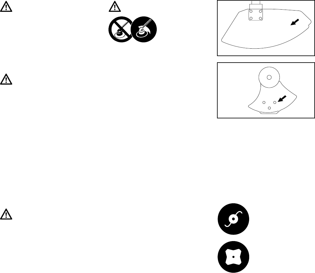
FS 260 C, FS 360 C
español / EE.UU
62
Mantenga los mangos limpios y secos
en todo momento; es particularmente
importante mantenerlos libres de
humedad, aceite, combustible, grasa o
resinas para garantizar que la máquina
pueda empuñarse firmemente para
mantenerla bajo control seguro.
Tal como se puede ver en la tabla, para
usar algunos de los accesorios de corte
puede ser necesario cambiar el
deflector, el tope limitador y/o el arnés.
Mantenga siempre el deflector (y la
faldilla en su caso) bien ajustado (vea en
su manual de instrucciones los capítulos
de "Montaje del deflector" y "Montaje del
accesorio de corte").
Las flechas (A) en el deflector y el
tope (B) (visto del fondo) muestran el
sentido correcto de rotación del
accesorio de corte. Sin embargo, al
verlo de arriba, el accesorio de corte gira
en sentido contrahorario.
Algunos de los siguientes símbolos
pueden aparecer grabados en el
exterior del deflector para indicar una
combinación aprobada de accesorio de
corte y deflector.
Advertencia!
No instale ningún accesorio de corte en
una máquina sin que todas las piezas
requeridas estén correctamente instala-
das. Si no se utilizan las piezas debidas
se puede causar el desprendimiento de
la cuchilla o el cabezal y lesionar grave-
mente al operador o a las personas que
encuentren en su proximidad.
Advertencia!
El accesorio de corte debe estar correc-
tamente apretado y en buenas
condiciones de trabajo. Busque piezas
sueltas (tuercas, tornillos, etc.) y cabe-
zales agrietados o dañados, o cuchillas
agrietadas, combadas, deformadas o
dañadas. Sustituya los cabezales o las
cuchillas dañados antes de usar la
herramienta motorizada. Mantenga las
cuchillas siempre afiladas.
Advertencia!
Asegúrese de que el casquillo de la
bujía esté firmemente colocado – un
casquillo suelto puede crear un arco
voltaico y encender los vapores del
combustible, provocando un incendio.
Advertencia!
Para reducir el
riesgo de sufrir
lesiones corpora-
les debido a la
pérdida de control
y/o al contacto con la cuchilla o el hilo y
los objetos arrojados, asegúrese que su
máquina está equipada con el deflector,
tope limitador y arnés correctos para el
tipo de accesorio de corte que está
usando (vea la tabla en el capítulo
"Combinaciones aprobadas de acceso-
rio de corte, deflector, tope limitador y
arnés").
El deflector puede usarse
en conjunto con las cabe-
zas segadoras.
El deflector puede usarse
en conjunto con las
cuchillas para cortar
pasto.
A
000BA006 KN
B
000BA007 KN
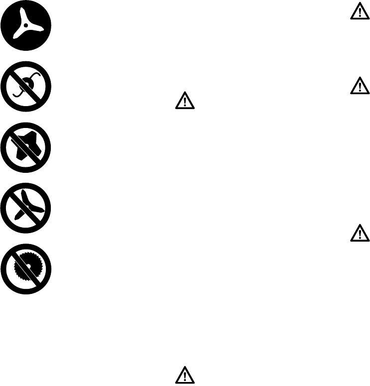
FS 260 C, FS 360 C
español / EE.UU
63
Ajuste el arnés y la empuñadura de
modo correspondiente a su estatura
antes de empezar a trabajar. La
máquina debe estar correctamente
equilibrada de la forma especificada en
el manual de instrucciones para un
control correcto y menos fatiga de
trabajo. Para prepararse para
emergencias, practique la liberación
rápida de la unidad del arnés.
Arranque
Arranque el motor al aire libre, por lo
menos 3 m (10 pies) del lugar en que lo
haya llenado.
Para las instrucciones específicas de
arranque, vea la sección
correspondiente en el manual del
usuario. Coloque la herramienta
motorizada sobre suelo firme u otra
superficie sólida en un lugar abierto.
Mantenga el equilibrio y elija un buen
punto de apoyo para los pies.
Tan pronto arranque, accione
inmediatamente por un breve momento
el gatillo de aceleración para
desconectarlo de la posición de
arranque y permitir que el motor se
desacelere a la marcha en vacío.
Con el motor funcionando a velocidad
de marcha en vacío solamente,
enganche la herramienta motorizada al
gancho de resorte de su arnés (vea el
capítulo correspondiente en este
manual).
Ajustes importantes
Si no puede regular correctamente el
ralentí, pida a su concesionario STIHL
que revise la herramienta motorizada y
haga los ajustes o reparaciones
correspondientes.
El deflector puede usarse
en conjunto con las
cuchillas para matorrales.
El deflector no debe
usarse en conjunto con
las cabezas segadoras.
El deflector no debe
usarse en conjunto con
las cuchillas para cortar
pasto.
El deflector no debe
usarse en conjunto con
las cuchillas para
matorrales.
El deflector no debe
usarse en conjunto con
las sierras circulares.
Advertencia!
Para reducir el riesgo de lesiones
debido al contacto con las cuchillas o el
hilo, esté absolutamente seguro que el
accesorio de corte se encuentra lejos
de su cuerpo y de todas las obstruccio-
nes y objetos, incluido el suelo, porque
al arrancar el motor, su velocidad será
lo suficientemente rápida para que el
embrague se engrane y haga girar el
accesorio de corte.
Advertencia!
Su herramienta motorizada es una
máquina que debe ser manejada por
solamente una persona. No deje que
otras personas estén en el lugar de tra-
bajo, aun durante el arranque.
Advertencia!
Para reducir el riesgo de sufrir lesiones
causadas por la pérdida de control, no
intente arrancar el motor de la herra-
mienta "por lanzamiento".
Advertencia!
Cuando tire del mango de arranque, no
enrolle la cuerda de arranque alrededor
de la mano. No deje que el mango retro-
ceda bruscamente, sino guíe la cuerda
de arranque para que se enrolle debida-
mente. Si no ejecuta este procedimiento
puede lastimarse la mano o los dedos y
también dañar el mecanismo de
arranque.
Advertencia!
Para reducir el riesgo de lesiones per-
sonales debido a la pérdida de control o
al contacto con el accesorio de corte en
movimiento, no use una máquina cuyo
régimen de marcha en vacío está mal
regulado. Cuando el régimen de mar-
cha en vacío está correctamente
regulado, el accesorio de corte no debe
moverse. Para instrucciones acerca de
cómo ajustar el régimen de marcha en
vacío, vea la sección correspondiente
del manual de instrucciones.
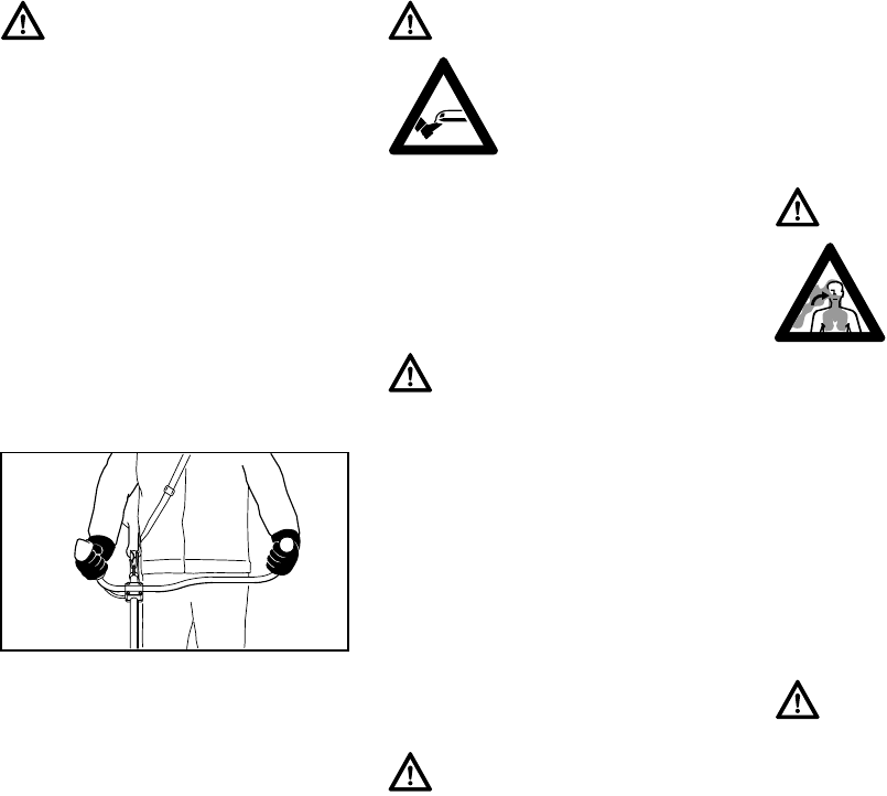
FS 260 C, FS 360 C
español / EE.UU
64
Durante el trabajo
Sujeción y control de la herramienta
motorizada
Al trabajar, siempre sujete la máquina
firmemente con ambas manos en los
mangos. Envuelva los dedos
firmemente en los mangos, ,
manteniéndolos sujetos entre los dedos
índice y pulgar.
Condiciones de trabajo
Maneje y arranque su herramienta
motorizada solamente al aire libre en un
lugar bien ventilado. Manéjela
solamente en condiciones de buena
visibilidad y a la luz del día. Trabaje con
mucho cuidado.
Advertencia!
Esta unidad tiene un sistema de encen-
dido que normalmente está listo para
usar en todo momento. Después de
usar la palanca de ajuste para detener
el motor, la misma regresa automática-
mente a la posición "activada". Si el
motor está caliente, puede ser posible
arrancarlo tirando de la cuerda de
arranque sin ajustes adicionales. Para
evitar el riesgo de lesiones, tenga sumo
cuidado y mantenga alejados a los
niños de la máquina.
002BA257 KN
Advertencia!
Nunca intente manejar la
herramienta motorizada
con una sola mano. La
pérdida de control de la
herramienta motorizada
puede ocasionar lesiones
graves o mortales. Para reducir el
riesgo de lesionarse, mantenga las
manos y los pies alejados del accesorio
de corte. No toque nunca con las manos
ni con cualquier parte del cuerpo un
accesorio de corte en movimiento.
Advertencia!
No trate de alcanzar más lejos de lo
debido. Mantenga los pies bien apoya-
dos y equilibrados en todo momento. Se
debe tener cuidado especial cuando las
condiciones del suelo son resbaladizas
(suelo húmedo, nieve) y en terreno difí-
cil y con mucha vegetación. Para evitar
tropezarse, esté atento a los obstáculos
ocultos tales como tocones, raíces y
zanjas. Para obtener un punto de apoyo
seguro, quite los matorrales y el mate-
rial cortado. Sea sumamente precavido
cuando trabaje en declives o terreno
irregular.
Advertencia!
Para reducir el riesgo de lesiones cau-
sadas por la pérdida del control, nunca
trabaje sobre una escalera o cualquier
otra superficie de soporte poco seguro.
Nunca mantenga el accesorio de corte
a una altura más arriba de la cintura.
Advertencia!
Tan pronto arranca, este
producto genera vapores
de escape tóxicos que
contienen productos quí-
micos (tales como
hidrocarburos sin quemar
y monóxido del carbono, incluyendo el
benceno) considerados como causan-
tes de enfermedades respiratorias,
cáncer, defectos de nacimiento u otra
toxicidad reproductora. Algunos de
estos gases (por ej., monóxido de car-
bono) pueden ser incoloros e inodoros.
Para reducir el riesgo de sufrir lesiones
graves o mortales por respirar gases
tóxicos, nunca haga funcionar la
máquina puertas adentro o en lugares
mal ventilados.
Advertencia!
Si la vegetación que se está cortando o
la tierra en el lugar está recubierta de
una sustancia química (tal como un
pesticida o herbicida activo), lea y siga
las instrucciones suministradas con la
sustancia en cuestión.
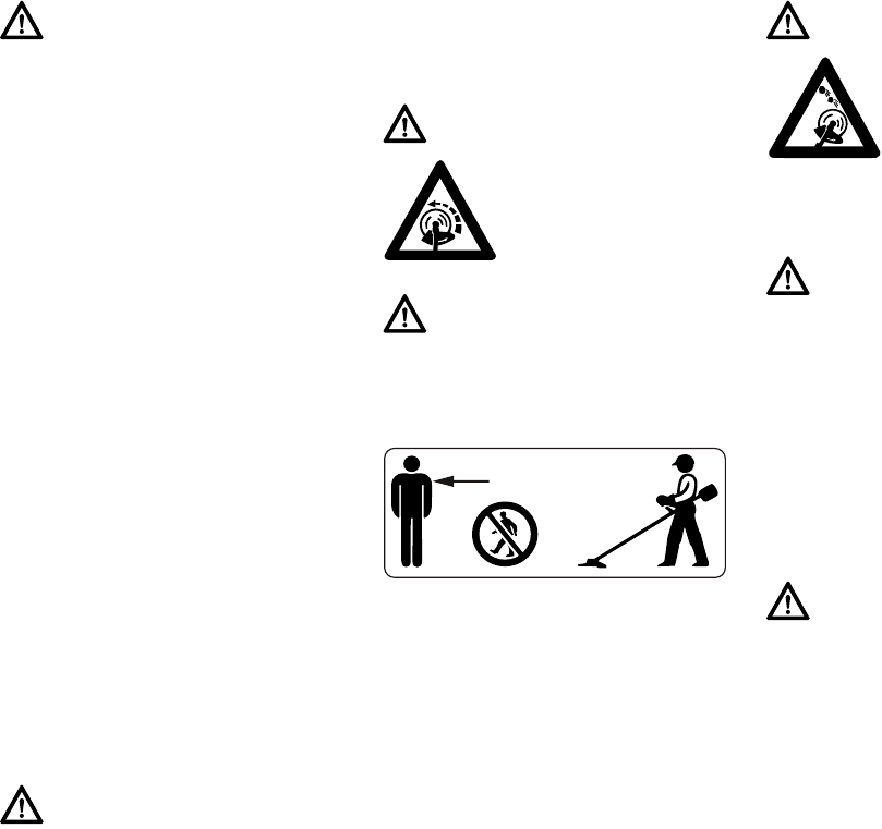
FS 260 C, FS 360 C
español / EE.UU
65
Instrucciones de manejo
En caso de emergencia, apague el
motor inmediatamente – mueva el
control deslizante / interruptor de parada
a STOP.
Para reducir el riesgo de ocasionar
lesiones a los ojos u otras partes del
cuerpo (vea el capítulo "Vestimenta
adecuada"), asegúrese que las
personas estén a por lo menos 15 m
(50 pies) de distancia de la máquina.
Para reducir el riesgo de ocasionar
daños a la propiedad, mantenga esta
distancia con respecto a los vehículos y
las ventanas. Los trabajadores que
deben quedar en la zona prohibida
también deben usar gafas o protección
ocular. Apague el motor
inmediatamente si se le aproxima
alguna persona.
Advertencia!
La inhalación de ciertos polvos, espe-
cialmente los polvos orgánicos, tales
como el moho o polen, puede provocar
reacciones alérgicas o asmáticas en las
personas sensibles. La inhalación repe-
tida o de grandes cantidades de polvo u
otros contaminantes del aire, especial-
mente los de partículas pequeñas
puede causar enfermedades respirato-
rias o de otro tipo. Controle el polvo en
su fuente, siempre que sea posible. Uti-
lice buenas prácticas de trabajo, tal
como trabajar de manera que el viento
o el proceso de corte dirija el polvo pro-
ducido por la herramienta motorizada
en sentido opuesto del operador.
Observe las recomendaciones emitidas
por EPA/OSHA/NIOSH y las asociacio-
nes de trabajo y los sindicatos con
respecto al polvo ("materia particu-
lada"). Cuando sea imposible eliminar
significativamente la inhalación del
polvo, es decir mantener el nivel cerca
del valor ambiente, el operador y las
personas que se encuentren en la cer-
canía siempre deberán usar un
respirador aprobado por NIOSH/MSHA
para el tipo de polvo presente en el
lugar.
Advertencia!
No maneje la herramienta motorizada
usando el bloqueo de acelerador para
arranque, pues no tendrá control de la
velocidad del motor.
Advertencia!
El accesorio de corte
sigue girando por un rato
después que se suelte el
gatillo de aceleración
(efecto de volante).
Advertencia!
El accesorio de corte giratorio puede
arrojar objetos extraños a gran distancia
directa o indirectamente.
15m (50ft)
Advertencia!
Antes de empezar a tra-
bajar, inspeccione el
área en busca de pie-
dras, vidrio, alambre,
pedazos de metal,
basura u otros objetos
sólidos. El accesorio de corte puede
arrojar los objetos de esta clase.
Advertencia!
La sierra despejadora normalmente se
usa a nivel del suelo con el accesorio de
corte paralelo al suelo. El uso de la sie-
rra despejadora sobre el nivel del suelo
o con el accesorio de corte perpendicu-
lar al suelo puede incrementar el riesgo
de lesiones, dado que el accesorio de
corte queda casi totalmente expuesto y
la herramienta motorizada es más difícil
de controlar. No use nunca la sierra
despejadora para recortar setos.
Advertencia!
Durante el corte, revise frecuentemente
el apriete y la condición del accesorio
de corte en intervalos regulares con el
motor y el accesorio parados. Si nota un
cambio en el comportamiento del acce-
sorio durante el trabajo, apague el
motor inmediatamente, espere hasta
que se pare el accesorio de corte y
revise el apriete de la tuerca que sujeta
el accesorio y revise la cuchilla o el
cabezal en busca de grietas, desgaste y
daños.

FS 260 C, FS 360 C
español / EE.UU
66
Advertencia!
Una cuchilla o un cabezal suelto puede
vibrar, agrietarse, romperse o salirse de
la sierra despejadora, lo que puede pro-
vocar lesiones graves o mortales.
Asegúrese que el accesorio de corte
esté correctamente apretado. Utilice la
llave suministrada o cualquier otra que
tenga el largo adecuado para obtener el
par de apriete adecuado. Si la cuchilla o
el cabezal se suelta después de haberlo
apretado correctamente, deje de usar la
máquina inmediatamente. La tuerca de
retención puede estar desgastada o
dañada y debe ser sustituida. Si la
cuchilla o el cabezal continúa afloján-
dose, consulte al concesionario STIHL.
No use nunca una sierra despejadora
con un accesorio de corte suelto.
Advertencia!
Sustituya inmediatamente un cabezal
trizado, dañado o desgastado o una
cuchilla trizada, combada, deformada,
dañada, desafilada o desgastada,
incluso si solamente hay rayas superfi-
ciales. Los accesorios en esa condición
pueden romperse a alta velocidad y
causar lesiones graves o mortales.
Advertencia!
Cuando utilice cuchillas rígidas, evite
cortar cerca de vallas, edificios, toco-
nes, piedras u otros objetos de ese tipo
que puedan causar contragolpe de la
herramienta motorizada o daños a la
cuchilla. Para ese tipo de trabajo, STIHL
recomienda el uso de cabezas con hilo
de nilón. Además, tenga en cuenta que
en estos casos aumenta la posibilidad
de que ocurran rebotes.
Advertencia!
Si el cabezal, la cuchilla o el deflector se
atasca o queda pegado, siempre apa-
gue el motor y asegúrese que el
accesorio de corte está detenido antes
de limpiarlo. Quite el pasto, las male-
zas, etc. de la cuchilla o de alrededor
del cabezal en intervalos regulares.
Advertencia!
Para reducir el riesgo de la rotación
inesperada del accesorio de corte y la
posibilidad de sufrir lesiones, siempre
apague el motor y quite el casquillo de
la bujía antes de sustituir el accesorio
de corte. Para reducir el riesgo de sufrir
lesiones, siempre apague el motor
antes de ajustar el largo del hilo de nilón
en las cabezas segadoras de ajuste
manual.
Advertencia!
Debido al riesgo de encendido no con-
trolado, no haga girar el motor con el
arrancador sin tener instalada la bujía o
el casquillo de la misma.
Advertencia!
La caja de engranajes está caliente
durante el funcionamiento de la
máquina. Para reducir el riesgo de
lesiones por quemaduras, no toque la
caja de engranajes cuando está
caliente.
Advertencia!
El silenciador y otros componentes del
motor (por ej., aletas del cilindro, bujía)
se calientan durante el funcionamiento
y permanecen calientes por un buen
rato después de apagar el motor. Para
reducir el riesgo de quemaduras, no
toque el silenciador y otros componen-
tes mientras están calientes.
Advertencia!
Para reducir el riesgo de incendio y
lesiones por quemadura, mantenga lim-
pia la zona alrededor del silenciador.
Quite el lubricante excesivo y toda la
basura tal como las agujas de pinos,
ramas u hojas. Deje que el motor se
enfríe apoyado sobre una superficie de
hormigón, metal, suelo raso o madera
maciza, lejos de cualquier sustancia
combustible.
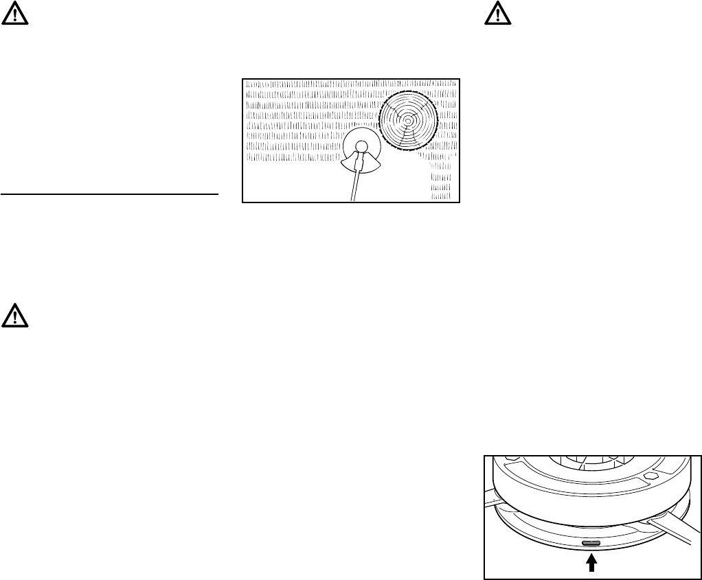
FS 260 C, FS 360 C
español / EE.UU
67
USO DEL ACCESORIO DE CORTE
Para una ilustración de los diversos
accesorios de corte y las instrucciones
sobre el montaje correcto, vea el
capítulo sobre "Montaje del accesorio
de corte" en su manual de instrucciones.
Uso de las cabezas segadoras
No use con un hilo de segado más largo
que el deseado. Con un deflector
debidamente instalado, la cuchilla
limitadora integral automáticamente
ajusta el hilo al largo adecuado.
Al usar la máquina con un hilo de nilón
de largo excesivo se aumenta la carga
del motor y se reduce la velocidad de
funcionamiento. Esto hace que el
embrague patine continuamente y
resulta en sobrecalentamiento y daño
de los componentes importantes (por
ejemplo, el embrague y las piezas de
polímero de la caja). Un efecto de este
tipo de daño puede ser la rotación del
accesorio de corte cuando el motor está
a la velocidad de ralentí.
Las cabezas segadoras deben usarse
solamente en las sierras despejadoras
equipadas con una cuchilla limitadora
del hilo en el deflector para mantener el
hilo al largo correcto (vea el capítulo
"Piezas principales" en el manual de
instrucciones).
Si las orillas del césped tienen árboles o
están bordeadas por un cerco, etc., es
mejor usar el cabezal de hilo de nilón.
Deja un corte más "suave" con menos
riesgo de dañar la corteza de los
árboles, etc., que si se usan cuchillas de
polímero.
Sin embargo, el cabezal PolyCut de
STIHL con cuchilla de polímero produce
un mejor corte si no hay plantas a lo
largo de la orilla del césped. No es
necesario afilar y las cuchillas de
polímero desgastadas se pueden
cambiar fácilmente.
Cabeza segadora SuperCut de STIHL
El hilo se avanza automáticamente. Los
hilos deshilachados se reemplazan con
un ajuste sencillo (consulte la hoja de
instrucciones provista con la cabeza
segadora).
Cabeza segadora AutoCut de STIHL
El hilo de corte de nilón avanza
automáticamente cuando se le golpea
contra el suelo (característica
TapAction).
Cabeza segadora TrimCut de STIHL
Los hilos deshilachados se reemplazan
con un ajuste sencillo (consulte la hoja
de instrucciones provista con la cabeza
segadora).
Cabeza segadora PolyCut de STIHL
Utiliza ya sea hilos de nilón o cuchillas
de polímero pivotantes no rígidas.
Advertencia!
Nunca modifique el silenciador. El silen-
ciador podría dañarse y causar el
aumento de la radiación de calor o chis-
pas, aumentando así el riesgo de
incendio y lesiones por quemadura.
Además, se podría dañar permanente-
mente el motor. Haga reparar el
silenciador únicamente por el concesio-
nario de servicio STIHL.
Advertencia!
Para reducir el riesgo de lesiones per-
sonales o la muerte debido al contacto
con las cuchillas y/o a la pérdida de con-
trol, nunca intente usar una cuchilla
metálica en una máquina modelo FS no
aprobada para esta aplicación.
002BA354 KN
Advertencia!
Para reducir el riesgo de lesiones gra-
ves, nunca use un hilo de alambre o
reforzado con metal ni ningún otro
material en lugar de los hilos de corte de
nilón. Es posible que unos pedazos de
alambre sean desprendidos y arrojados
a gran velocidad contra el operador o
terceros.
002BA396 KN
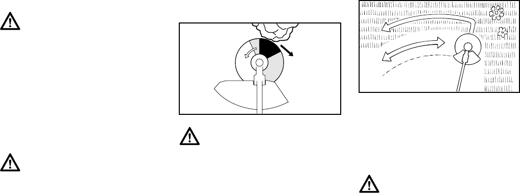
FS 260 C, FS 360 C
español / EE.UU
68
Observe los indicadores de
desgaste.
El riesgo de expulsión (disparo de la
cuchilla) existe con todas las
cuchillas rígidas
Esta expulsión (disparo de la cuchilla)
puede ocasionar la pérdida de control
de la herramienta motorizada y provocar
lesiones graves o mortales al usuario o
a personas en su proximidad. Para
reducir el riesgo, es necesario extremar
las precauciones a la hora de cortar con
la zona sombreada de cualquier cuchilla
rígida.
Uso de la cuchilla de cortar pasto
Todos los tipos de pasto y malezas se
pueden cortar fácilmente con la cuchilla
de cortar pasto. Para ello, la
herramienta motorizada se mueve en
forma de arco, como si fuera una
guadaña.
La función de la cuchilla de 4 dientes es
la de cortar pasto y malezas. Tiene 4
cuchillos con filo en los dos lados, esto
es, en las partes delantera y trasera.
Cuando los bordes cortantes en un lado
se desafilan, es posible invertir la
cuchilla para usar los bordes cortantes
en el otro lado.
Recomendamos la cuchilla de 8 dientes
para los casos en que haya que cortar
helechos o cañas.
Los dos tipos de cuchillas para cortar
pasto deben ser afiladas al desgastarse
sus filos o bordes cortantes.
Advertencia!
En la base (periferia) de la PolyCut hay
tres marcas rectangulares de límite de
desgaste. Para reducir el riesgo de
lesiones graves causadas por la rotura
de la cabeza o de las cuchillas, la
PolyCut no debe ser utilizada cuando se
ha desgastado hasta una de estas mar-
cas. Es importante seguir las
instrucciones para el mantenimiento
suministradas con la cabeza segadora.
Advertencia!
Si se pasan por alto las marcas de límite
de desgaste, el accesorio de corte
puede astillarse y lanzar objetos que
puedan lesionar al operador o a terce-
ros. Para reducir el riesgo de lesiones
causadas por la rotura de la cuchilla,
evite el contacto con las piedras, el
metal u otros objetos sólidos. Revise la
condición de las cuchillas PolyCut en
intervalos regulares. Siempre sustituya
todas las cuchillas si se encuentra una
fisura en una cuchilla.
Advertencia!
La expulsión (disparo de la cuchilla) es
el movimiento repentino y no controlado
hacia el lado derecho o posterior del
operador que puede suceder cuando la
zona sombreada (especialmente la
zona muy oscura) de la cuchilla giratoria
entra en contacto con un objeto macizo
tal como un árbol, roca, arbusto o
pared. La rápida rotación en sentido
contrahorario puede ser detenida o ami-
norada y el accesorio de corte puede
salir despedido hacia la derecha o
detrás.
002BA135 KN
Advertencia!
Para reducir el riesgo de lesiones gra-
ves o mortales debido a la rotura de la
cuchilla, no intente nunca cortar madera
con esta cuchilla.
002BA355 KN
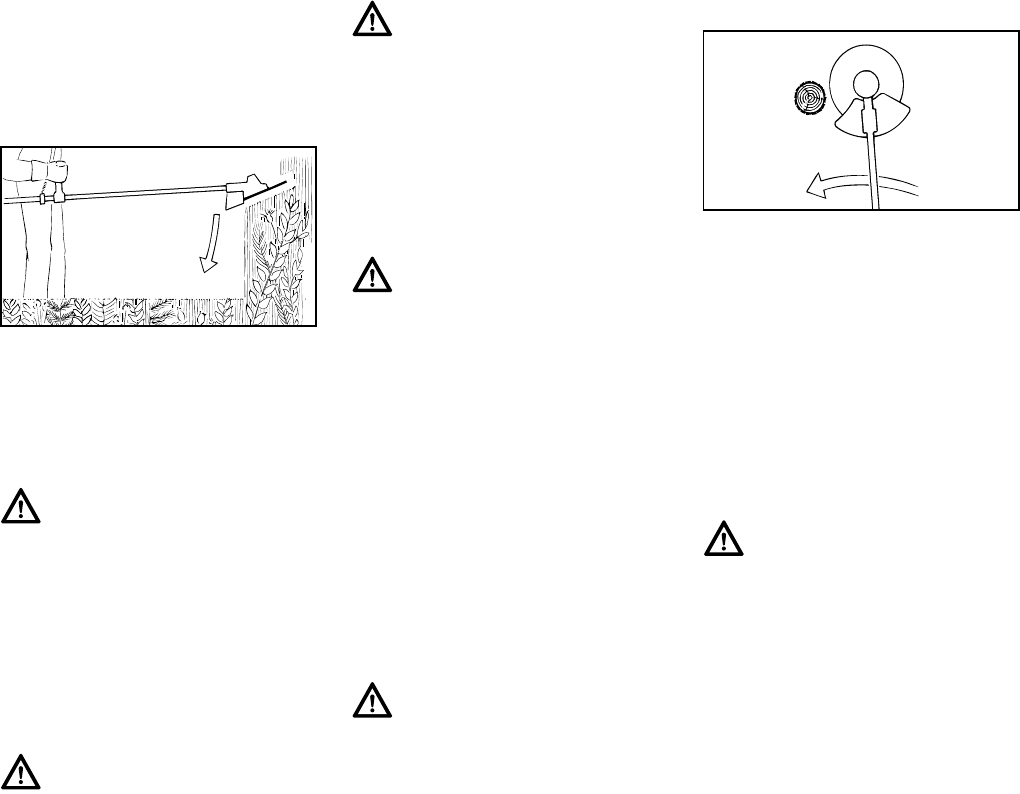
FS 260 C, FS 360 C
español / EE.UU
69
Uso de la cuchilla para matorrales
Cuando se instala la cuchilla para
matorrales en la herramienta
motorizada, es adecuada para cortar
desde pasto hasta malezas, plantas
silvestres y arbustos.
Para cortar plantas y arbustos
silvestres, baje la cuchilla giratoria para
matorrales hasta la planta para crear un
efecto de picado, pero mantener la
herramienta por debajo del nivel de la
cintura en todo momento.
Utilice la herramienta motorizada como
una guadaña para cortar pasto, es decir,
haga pasadas en uno y otro sentido,
describiendo un arco.
Uso de la sierra circular
Las sierras circulares son adecuadas
para recortar matorrales y cortar árboles
pequeños de hasta 7 cm (2-3/4 pulg) de
diámetro. No intente cortar árboles cuyo
diámetro sea mayor, puesto que la
cuchilla puede atorarse o tirar de la
orilladora / cortadora de matorrales
repentinamente hacia adelante. Esto
puede dañar la cuchilla o causar la
pérdida de control de la herramienta
motorizada, lo cual puede resultar en
lesiones personales graves. Utilice una
motosierra para estos tipos de trabajos.
Si se usa la sierra despejadora con una
sierra circular para cortar árboles
pequeños, STIHL recomienda retirar el
deflector estándar y sustituirlo con el
deflector de tope especial (vea el
capítulo "Montaje del deflector"). Este
tope ayuda a mantener la máquina en
su posición contra el árbol durante el
proceso de corte. Los usuarios con poca
Advertencia!
Tenga sumo cuidado al emplear este
método de corte. Cuanto mayor sea la
distancia entre el accesorio de corte y el
suelo, mayor es el riesgo de perder el
control o lanzar objetos por los lados.
Advertencia!
Al cortar materiales parecidos a
madera, utilice el lado izquierdo de la
cuchilla para evitar la "expulsión" (dis-
paro de la cuchilla).
002BA066 KN
Advertencia!
El uso incorrecto de una cuchilla para
matorrales puede causar agrietaciones,
picaduras o roturas. Las piezas de
cuchilla lanzadas pueden causar lesio-
nes graves o mortales al operador o a
terceros. Para reducir el riesgo de lesio-
nes, evite el contacto con objetos duros
o macizos tales como piedras, rocas u
objetos metálicos.
Advertencia!
Al cortar árboles jóvenes y otros mate-
riales de hasta 2 cm (3/4 pulg) de
diámetro, utilice el lado izquierdo de la
cuchilla para evitar la "expulsión" de la
misma (consulte la sección "El riesgo
de expulsión (disparo de la cuchilla)
existe con todas las cuchillas rígidas").
No intente cortar materiales parecidos a
la madera cuyo diámetro sea mayor,
puesto que la cuchilla puede atorarse o
tirar de la herramienta motorizada
repentinamente hacia adelante. Esto
puede dañar la cuchilla o la herramienta
motorizada, o causar la pérdida de con-
trol de la misma, lo cual puede resultar
en lesiones personales. Utilice una sie-
rra circular para estos tipos de trabajos.
Advertencia!
Inspeccione la cuchilla para matorrales
a intervalos periódicos y cortos en
busca de daños. No continúe traba-
jando con una cuchilla para matorrales
que esté dañada. Afile la cuchilla para
matorrales periódicamente (cuando ha
perdido su filo de modo apreciable).
Advertencia!
Para reducir el riesgo de rayar y / o rom-
per la cuchilla, evite todo contacto con
piedras, rocas o el suelo. Afile las cuchi-
llas oportunamente de la manera
especificada – los dientes desafilados
pueden hacer que la cuchilla se agriete
o se rompa.
002BA067 KN
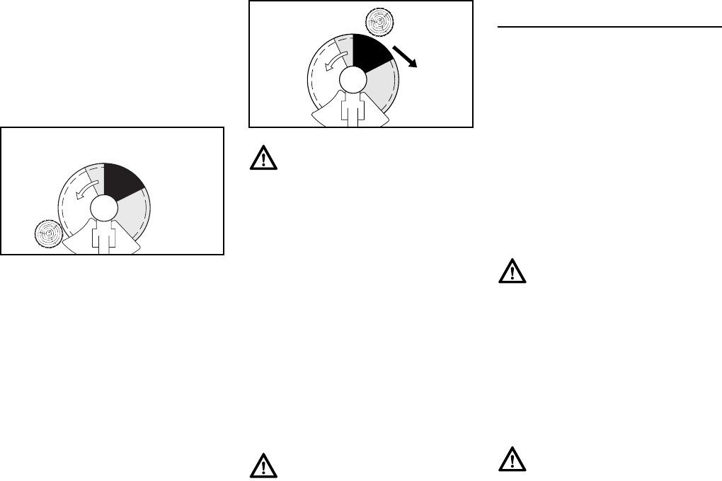
FS 260 C, FS 360 C
español / EE.UU
70
experiencia deben colocar el lado
izquierdo del tope contra el tronco del
árbol antes de iniciar el corte. Esto
mantiene la sierra despejadora contra el
árbol durante la operación de corte y
reduce el riesgo de pérdida de control y
posible expulsión (descrito más arriba y
brevemente otra vez más abajo).
Antes de iniciar el corte, acelere el motor
a su velocidad máxima. Efectúe el corte
aplicando presión uniforme. STIHL
recomienda aplicar la sierra circular por
el lado derecho del árbol, usando la
zona no sombreada de la cuchilla, tal
como se muestra en la ilustración de
arriba. Durante la tala de árboles pequeños,
mantenga una distancia de por lo menos
dos veces el largo del árbol con
respecto a la persona más cercana.
MANTENIMIENTO, REPARACIÓN Y
ALMACENAMIENTO
Los trabajos de mantenimiento,
reemplazo o reparación de los
dispositivos y sistemas de control de
emisiones de escape pueden ser
realizados por cualquier taller o
técnico de motores no diseñados
para vehículos. Sin embargo, si usted
está reclamando cobertura de
garantía para algún componente que
no ha sido reparado o mantenido
debidamente, o cuando se utilizan
repuestos no autorizados, STIHL
puede denegar la garantía.
Siga precisamente las instrucciones de
mantenimiento y reparación dadas en
las secciones correspondientes del
manual de instrucciones.
002BA214 ST
Advertencia!
El riesgo de expulsión de la cuchilla es
mayor cuando se corta en la zona som-
breada oscura. Para reducir el riesgo de
expulsión y las lesiones consecuentes,
no utilice esta zona de la sierra circular
para cortar árboles ni arbustos. Las téc-
nicas especiales que utilizan las zonas
sombreadas más claras de la cuchilla
para cortar arbustos y árboles sólo
deben ser usadas por operadores
expertos con capacitación especiali-
zada en cuanto al uso y control de la
sierra despejadora.
Advertencia!
Para reducir el riesgo de lesiones cau-
sadas por los objetos lanzados o por el
contacto con la cuchilla o el cabezal,
cerciórese de volver a instalar el deflec-
tor estándar cuando no está usando
una sierra circular.
002BA068 KN
Advertencia!
Utilice solamente piezas de repuesto de
STIHL para el mantenimiento y la repa-
ración. El uso de piezas no fabricadas
por STIHL puede causar lesiones gra-
ves o mortales.
Advertencia!
Siempre apague el motor y verifique
que el accesorio de corte está parado
antes de llevar a cabo cualquier trabajo
de mantenimiento, reparación o lim-
pieza de la herramienta motorizada. No
intente hacer ningún trabajo de mante-
nimiento o reparación que no esté
descrito en su manual de instrucciones.
Este tipo de trabajo debe ser realizado
únicamente por el concesionario de ser-
vicio de STIHL.

FS 260 C, FS 360 C
español / EE.UU
71
Use guantes para manipular o reparar
las cuchillas.
Mantenga las cuchillas afiladas. Apriete
todas las tuercas, pernos y tornillos,
excepto los tornillos de ajuste del
carburador, después de cada uso.
No limpie la máquina con una lavadora
a presión. El chorro fuerte de agua
puede dañar las piezas de la máquina.
Guarde la herramienta motorizada en un
lugar seco y elevado o con llave lejos del
alcance de los niños.
Antes de guardar la máquina durante un
período de más de algunos días,
siempre vacíe el tanque de combustible.
Consulte el capítulo "Almacenamiento
de la máquina" en el manual de
instrucciones.
Advertencia!
Use la bujía especificada y asegúrese
de que ella y el cable de encendido
están limpios y en buen estado. Siem-
pre inserte el casquillo de la bujía bien
apretado en el borne de la bujía del
tamaño adecuado. (Nota: Si el borne
tiene una tuerca adaptadora SAE des-
montable, tiene que ser firmemente
instalada.) Una conexión suelta entre la
bujía y el conector del cable de encen-
dido en el casquillo puede crear un arco
voltaico y encender los vapores del
combustible y provocar un incendio.
Advertencia!
No pruebe nunca el sistema de encen-
dido con el casquillo desconectado de
la bujía, o sin tener instalada la bujía, ya
que las chispas al descubierto pueden
causar un incendio.
Advertencia!
Nunca maneje su herramienta motori-
zada si el silenciador está dañado, se
ha perdido o si fue modificado. Un silen-
ciador mal cuidado aumenta el riesgo
de incendio y puede causar pérdida de
audición. Si el silenciador está equipado
con un chispero para reducir el riesgo
de incendio, no maneje nunca su herra-
mienta motorizada si le falta el chispero
o está dañado. Recuerde que el riesgo
de incendios forestales es mayor
durante las estaciones calurosas y
secas.
Advertencia!
Nunca repare los accesorios de corte
dañados aplicándoles soldadura, ende-
rezándolos o modificándoles su forma.
Esto puede causar el desprendimiento
de alguna pieza del accesorio de corte
y producir lesiones graves o mortales.
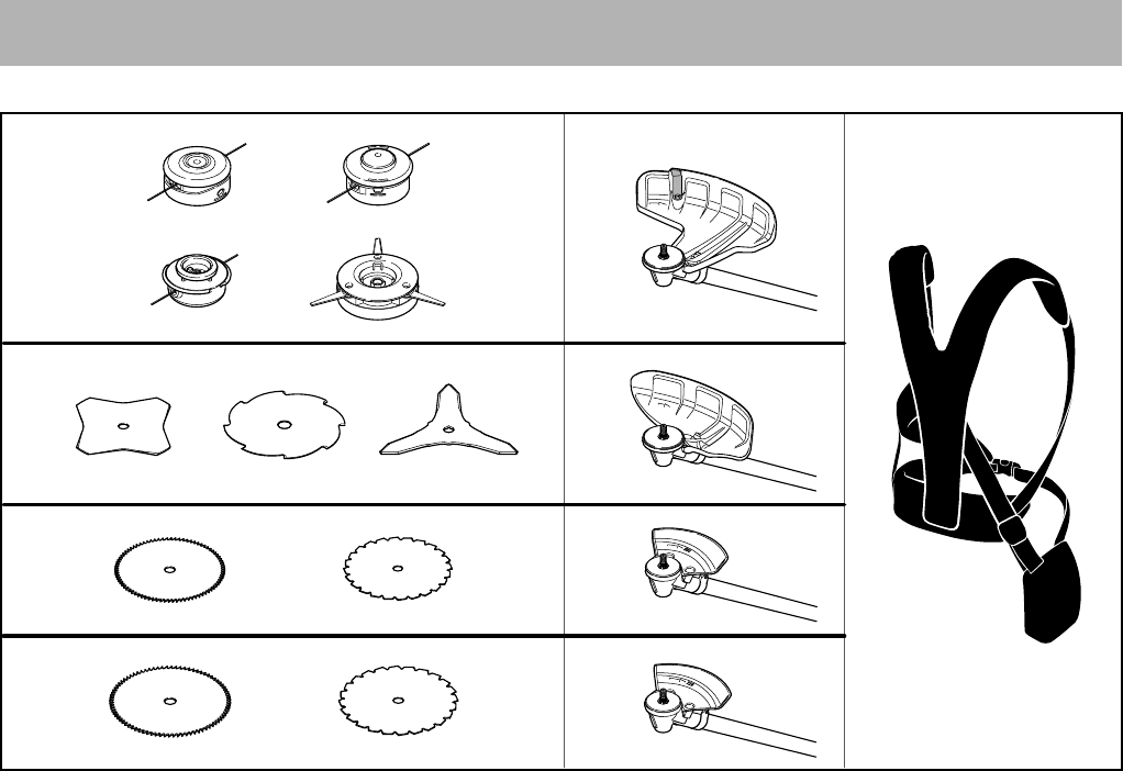
FS 260 C, FS 360 C
español / EE.UU
72
Combinaciones aprobadas de accesorio de corte, deflector, tope limitador y arnés
Accesorio de corte Deflector, límite de tope Arnés
7
681BA171 KN
1
4
5
89
6
12
13
14
16
3
2
10 11 15
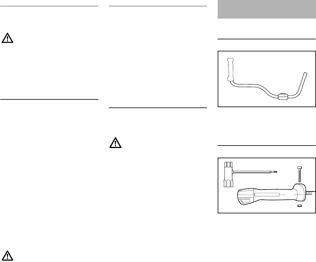
FS 260 C, FS 360 C
español / EE.UU
73
Combinaciones permisibles
Elija la combinación indicada en la tabla
de acuerdo con el accesorio de corte.
Accesorios de corte
Cabezas segadoras
1STIHL SuperCut 40-2
2STIHL AutoCut 40-2
3STIHL TrimCut 41-2
4STIHL PolyCut 41-3
Accesorios de corte metálicos
5Cuchilla para pasto 230-4
6Cuchilla para pasto 255-8
7Cuchilla para matorrales 300-3
8Sierra circular 200 (dientes
raspadores)
9Sierra circular 200 (dientes tipo
cincel)
10 Sierra circular 225 (dientes
raspadores)
11 Sierra circular 225 (dientes tipo
cincel)
Deflectores, topes limitadores
Deflectores
12 Deflector sólo para cabezas
segadoras
13 Deflector para herramientas de
segado; elementos 5 al 7
Topes limitadores
14 Tope limitador para sierras
circulares 200
15 Tope limitador para sierras
circulares 225
Arneses
16 Es obligatorio usar el arnés
completo
Montaje del manillar tipo bicicleta
con soporte de mango giratorio
La máquina se suministra con piezas
moldeadas de fijación (1) montadas en
el manillar (2).
Montaje del mango de control
NSaque el tornillo (3) y quite la
tuerca (4) del mango de control (5).
Por motivos de seguridad,
solamente los accesorios de
corte, los deflectores y/o los topes
limitadores que aparecen en el
mismo renglón de la tabla pueden
combinarse. No se permiten otras
combinaciones debido al ¡riesgo
de accidentes!
Las sierras circulares hechas de
otro material no metálico no
deben usarse.
Advertencia!
Basado en el accesorio de corte en uso:
Seleccione un deflector adecuado para
reducir el riesgo de lesiones causadas
por los objetos lanzados y por el con-
tacto con el accesorio de corte.
Para reducir el riesgo de sufrir lesiones
debido a la pérdida de control y al con-
tacto con el accesorio de corte,
asegúrese que su máquina está equi-
pada con el mango y arnés correctos.
Utilice las cuchillas metálicas para corte
de pasto, cuchillas para arbustos y dis-
cos de sierra circular con esta máquina
únicamente si la misma está provista
con un manillar tipo bicicleta.
No utilice cuchillas de polímero rígidas
con esta máquina.
Montaje del manillar
2
1
6BA018 KN
3
4
5
002BA352 KN
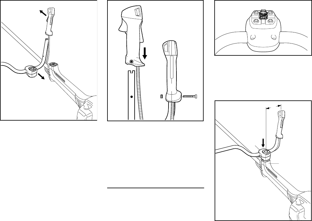
FS 260 C, FS 360 C
español / EE.UU
74
NAlinee el mango de control (5) con
respecto al manillar (2): El gatillo de
aceleración (6) debe apuntar hacia
la caja de engranajes y el tornillo de
fijación (7) hacia el motor.
NMantenga el mango de control (5)
en esa posición, empújelo en el
extremo del manillar (2) y alinee los
orificios (8).
NColoque la tuerca (4) en el mango
de control (5), introduzca el
tornillo (3) y apriételo firmemente.
Armado del soporte del mango
Para armar el soporte de mango
giratorio se coloca un resorte en las
piezas moldeadas de fijación y se
instalan las mismas en el soporte del
mango.
NUtilice el resorte (9) del juego de
piezas suministrado con la
máquina.
NColoque el resorte (9) en la pieza
moldeada de fijación inferior (10).
NColoque las piezas moldeadas de
fijación (1) con el manillar (2) en el
soporte del mango (11).
7
5
6BA002 KN
6
2
8
6BA019 KN
2
83
5
4
6BA001 KN
9
10
11
1
6BA020 KN
2
A
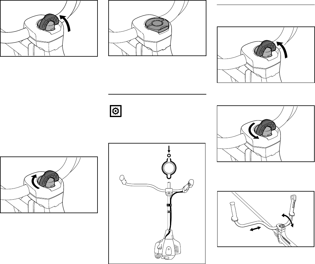
FS 260 C, FS 360 C
español / EE.UU
75
NEleve la empuñadura del tornillo
mariposa (7) a la posición vertical.
NGire el tornillo mariposa hasta el
tope en sentido contrahorario.
NEmpuje el tornillo mariposa hasta el
tope en el soporte del mango y
atorníllelo, pero no al valor de
apriete final.
NAjuste el manillar (2) de modo que
la distancia A no exceda 15 cm.
NAlinee el manillar perpendicular al
tubo de mando.
NGire el tornillo mariposa hasta el
tope en sentido horario.
NPliegue la empuñadura del tornillo
mariposa hasta que quede al ras.
FS 260 C: Instalación del cable del
acelerador
NEmpuje el cable del acelerador (12)
en el retenedor (13).
Ajuste del manillar
Apertura del tornillo mariposa
NEleve la empuñadura del tornillo
mariposa a la posición vertical.
NGire el tornillo mariposa en sentido
contrahorario hasta que se pueda
mover el soporte del mango.
NMueva el manillar a la posición
requerida.
6BA003 KN
2
7
6BA005 KN
No tuerza el cable del acelerador
ni forme curvas agudas al colocar
el mismo – asegúrese de que el
gatillo de aceleración se mueva
libremente.
6BA006 KN
12
13
002BA439 KN
13
12
6BA023 KN
6BA004 KN
6BA007 KN
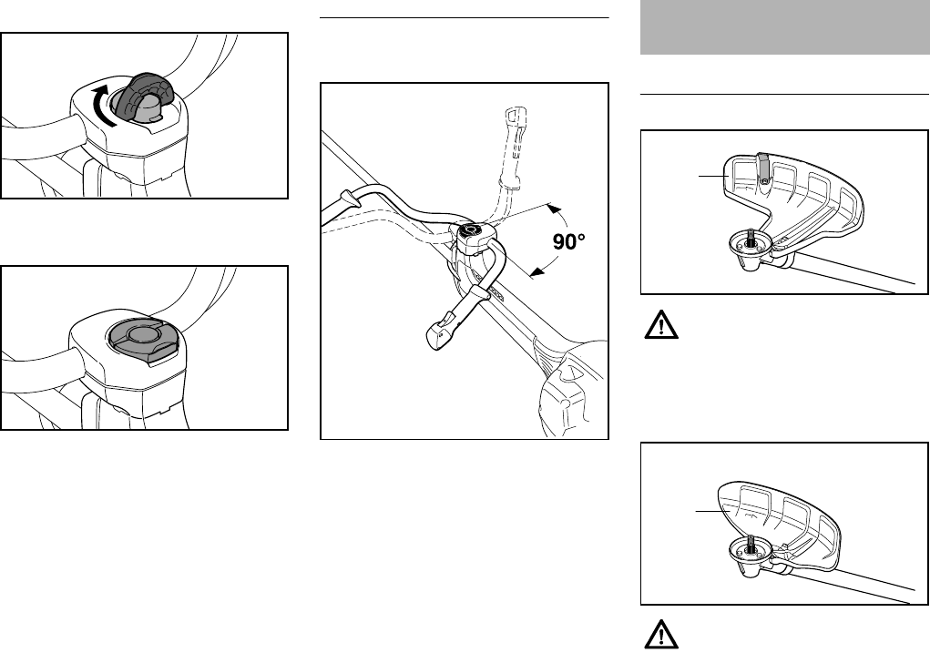
FS 260 C, FS 360 C
español / EE.UU
76
Cierre del tornillo mariposa
NGire el tornillo mariposa hasta el
tope en sentido horario.
NPliegue la empuñadura del tornillo
mariposa hasta que quede al ras.
Giro del manillar
Posición de transporte
NSuelte el tornillo mariposa (7) y
destorníllelo hasta que el
manillar (2) pueda girarse en
sentido horario.
NGire el manillar en 90° y luego gire
hacia abajo los mangos.
NApriete el tornillo mariposa (7)
firmemente.
Posición de trabajo
NInvierta la secuencia descrita arriba
para girar los mangos hacia arriba y
girar el manillar en sentido
contrahorario.
Uso del deflector apropiado
6BA005 KN
6BA006 KN
7
6BA008 KN
2
Montaje de la barra de
defensa
El deflector (1) está aprobado
para uso únicamente con cabezas
segadoras, por lo cual es
necesario instalar el deflector (1)
antes de fijar una cabeza
segadora.
El deflector (2) está aprobado
para uso únicamente con hojas
segadoras, por lo cual es
necesario instalar el deflector (2)
antes de fijar una hoja segadora
de pasto.
1
002BA401 KN
2
002BA402 KN
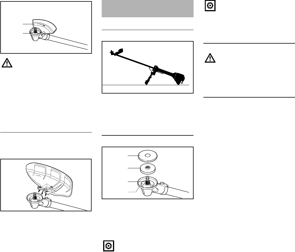
FS 260 C, FS 360 C
español / EE.UU
77
Montaje del deflector
Los deflectores (1-3) se conectan a la
caja de engranajes de la misma manera.
NColoque el deflector en la caja de
engranajes (5),
NAtornille y apriete los tornillos (6)
Preparación de la máquina
NColoque la máquina en el suelo de
modo que el montaje para los
accesorios de corte quede
orientado hacia arriba.
Fijación de la placa de empuje
NEmpuje la placa de empuje (1) y la
arandela protectora (2) en el eje (3)
La máquina se equipa en fábrica con un
anillo protector (4) para las
herramientas de corte.
Montaje del accesorio de corte
Montaje de las cabezas segadoras
STIHL SuperCut, STIHL AutoCut,
STIHL TrimCut, STIHL PolyCut
NUtilice el anillo protector con las
herramientas de segado
NFijación del deflector para las
cabezas segadoras
El tope limitador (3) está
aprobado para uso únicamente
con discos de sierra circular, por
lo cual es necesario instalar el
limitador (3) y sustituir el anillo
protector (4) antes de fijar un
disco de sierra circular, consulte
"Montaje del accesorio de corte" /
"Montaje de discos de sierra
circular".
3
002BA433 KN
4
6
5
002BA434 KN
Montaje del accesorio de
corte
La placa de empuje (1) de la caja
de engranajes es necesaria para
fijar todos los accesorios de corte.
002BA406 KN
002BA407 KN
1
2
3
4
La arandela protectora (2) en la
caja de engranajes es necesaria
para fijar todos los accesorios de
corte, salvo los discos de sierra
circular.
Utilice el deflector adecuado para
el accesorio de corte – vea
"Montaje del deflector".
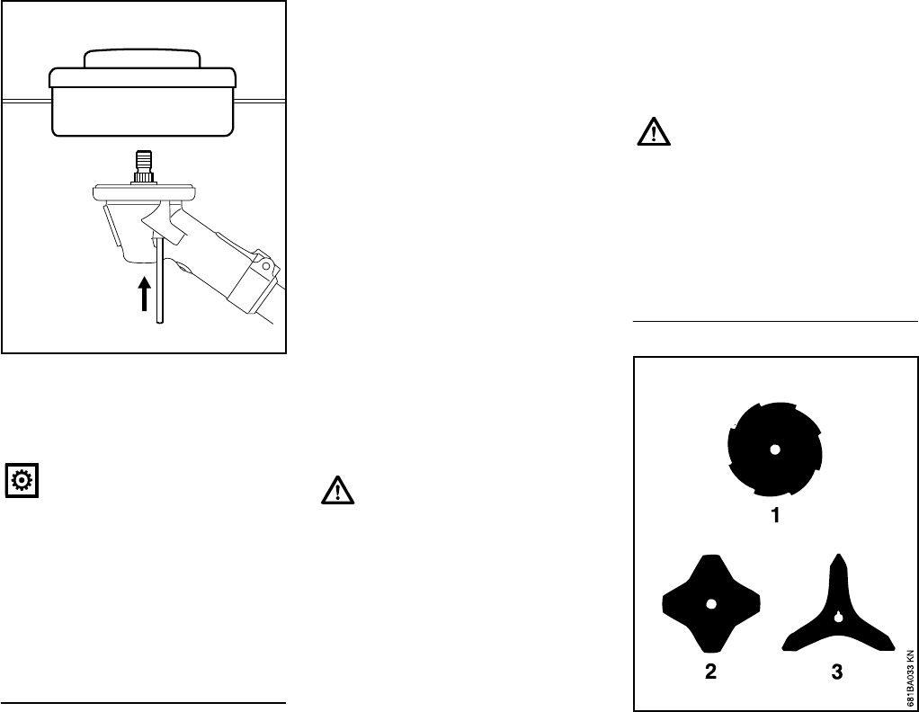
FS 260 C, FS 360 C
español / EE.UU
78
NBloquee el eje
NGire la cabeza segadora en sentido
contrahorario sobre el eje (1) y
apriétela.
Guarde la hoja de información de la
cabeza segadora en un lugar seguro.
Retiro de la cabeza segadora
NBloquee el eje
NDestornille la cabeza segadora en
sentido horario.
Alimentación del hilo de segado
La hoja de información de la cabeza
segadora contiene una descripción
detallada.
Cabeza segadora SuperCut
El hilo se alimenta automáticamente
durante el segado y se recorta al largo
óptimo por medio de una cuchilla en el
deflector. El hilo se alimenta únicamente
si ambos extremos del hilo miden por lo
menos 6 cm de largo.
Cabeza segadora AutoCut
NSujete la máquina sobre una
sección del prado con el motor en
marcha (la cabeza segadora
deberá girar)
NGolpee levemente la cabeza
segadora contra el suelo – el hilo se
alimenta automáticamente y se
recorta al largo óptimo por medio de
la cuchilla del deflector
El hilo se alimenta únicamente si ambos
extremos del hilo miden por lo menos
2.5 cm de largo.
Cabeza segadora TrimCut
NTire de la caja del carrete hacia
arriba – gírela en sentido
contrahorario aprox. 1/6 de vuelta
hasta que se enganche y luego
suéltela para que retorne por acción
de resorte.
NTire de los extremos del hilo hacia
fuera
Repita esta operación según sea
necesario hasta que ambos extremos
del hilo midan aprox. 13 cm de largo.
El giro desde el punto en que se emite
un chasquido hasta el chasquido
siguiente suelta aproximadamente 4 cm
del hilo.
Cabeza segadora PolyCut
Proceda de la manera descrita en la
hoja de información de la cabeza
segadora.
Instalación de hojas segadoras de
pasto, cuchillas para arbustos
Con la hoja de segado de pasto
2558 (1), los filos deberán quedar
orientados en sentido horario.
Quite la herramienta usada para
bloquear el eje.
1
002BA408 KN
Siempre apague el motor antes
de avanzar el hilo con la mano ya
que ¡de lo contrario hay un riesgo
de lesiones!
Siempre apague el motor antes
de cargar el hilo con la mano ya
que ¡de lo contrario hay un riesgo
de lesiones!
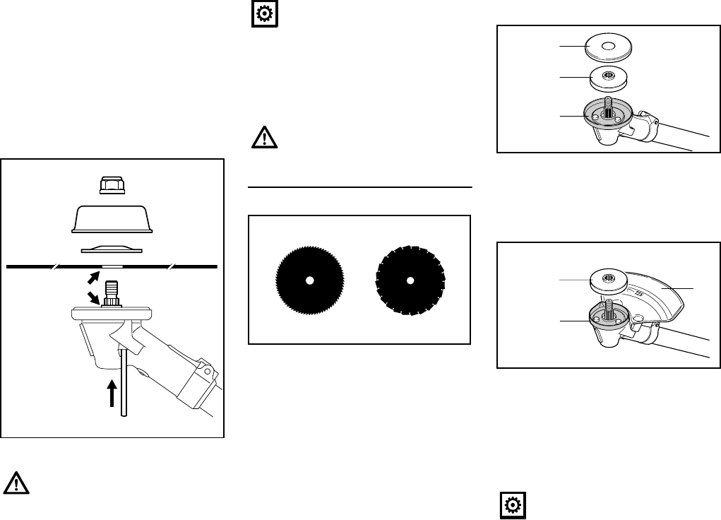
FS 260 C, FS 360 C
español / EE.UU
79
Los accesorios de corte con 3 ó
4 hojas (2, 3) pueden orientarse en
cualquier sentido – invierta este tipo de
accesorios de corte periódicamente
para evitar el desgaste desparejo.
NUtilice el anillo protector con las
herramientas de segado
NFijación del deflector para
herramientas segadoras metálicas
NColoque el accesorio de corte (1)
NColoque la arandela de empuje (2)
– la curvatura queda orientada
hacia arriba.
NColoque la placa de empuje (3)
NBloquee el eje
NEnrosque la tuerca (4) en sentido
contrahorario y apriétela
Retire los accesorios de corte
NBloquee el eje
NDestornille la tuerca en sentido
horario
Fijación de discos de sierra circular
Con los discos de sierra circular, los filos
deberán quedar orientados en sentido
horario.
Para fijar discos de sierra circular, se
utiliza un juego de topes limitadores
como accesorio especial que incluye el
tope limitador y un anillo protector para
los discos de sierra circular.
Cambio de anillo protector
NQuite la arandela protectora (3) y la
placa de empuje (4).
NQuite el anillo protector (5) para
herramientas de segado
NFije el anillo protector (6) para
discos de sierra circular
NMonte la placa de empuje (4) en el
eje
NFije el tope limitador (7) para discos
de sierra circular
El collar (a) deberá engancharse
en el agujero (b) del accesorio de
corte.
2
3
1
4
002BA409 KN
b
a
Quite la herramienta usada para
bloquear el eje.
Una tuerca muy floja debe
sustituirse.
681BA165 KN
No utilice la arandela
protectora (3) para discos de
sierra circular.
002BA424 KN
4
3
5
7
002BA425 KN
6
4
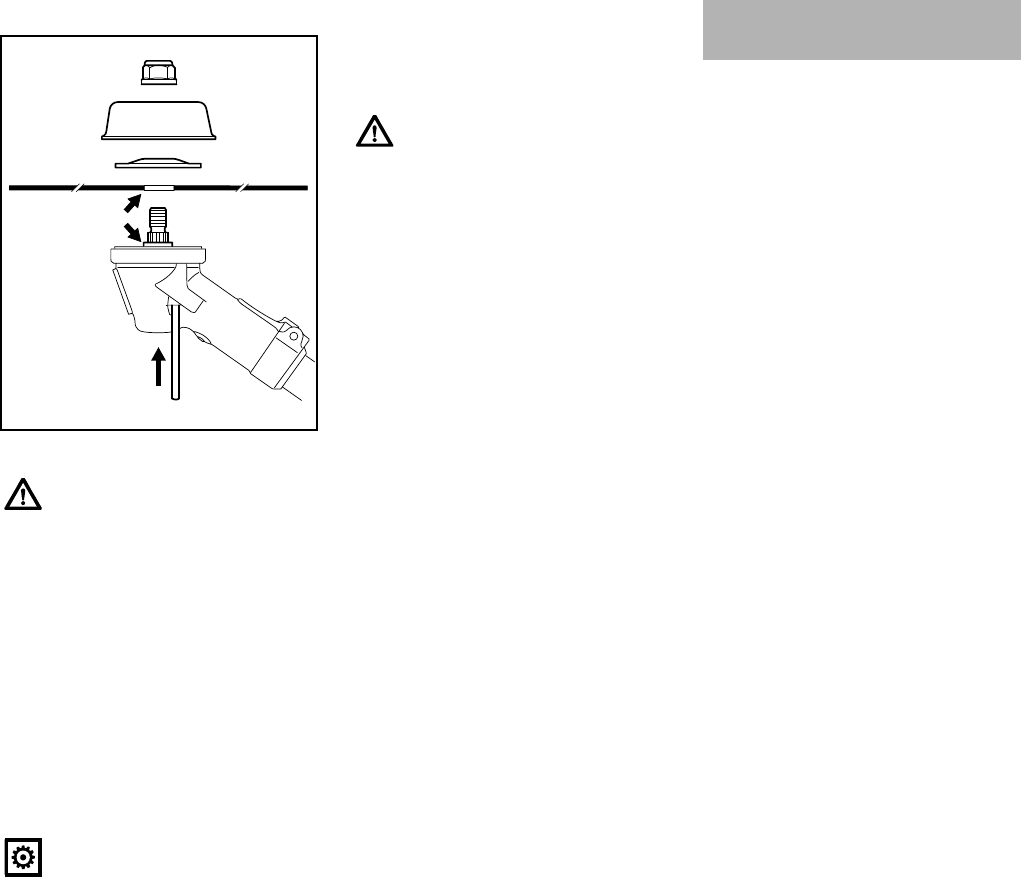
FS 260 C, FS 360 C
español / EE.UU
80
Montaje del accesorio de corte
NColoque el accesorio de corte (1)
NColoque la arandela de empuje (2)
– la curvatura queda orientada
hacia arriba.
NColoque la placa de empuje (3)
La placa de empuje (3) para aserrado,
que permite aprovechar la profundidad
de corte total del disco de sierra circular,
se ofrece como accesorio especial.
NBloquee el eje
NEnrosque la tuerca (4) en sentido
contrahorario y apriétela
Retire los accesorios de corte
NBloquee el eje
NDestornille la tuerca en sentido
horario Este motor está certificado para
funcionar con una mezcla de 50 a 1 de
gasolina sin plomo y aceite STIHL para
motores de dos tiempos.
Su motor requiere una mezcla de
gasolina de alta calidad y aceite de
calidad para motores de dos tiempos
enfriados por aire.
Use gasolina sin plomo regular con un
octanaje mínimo de 89 (R+M/2). Si el
octanaje de la gasolina regular en su
zona es más bajo, use combustible sin
plomo superior.
El combustible de octanaje bajo puede
aumentar la temperatura de
funcionamiento del motor. Esto, a su
vez, aumenta el riesgo de que se
agarrote el pistón y se dañe el motor.
La composición química del
combustible también es importante.
Algunos aditivos de combustible no
solamente tienen efectos perjudiciales
en los elastómeros (diafragmas de
carburador, sellos de aceite, tuberías de
combustible, etc.), sino también en las
piezas fundidas de magnesio y en los
convertidores catalíticos. Esto podría
causar problemas de funcionamiento e
incluso daño del motor. Por esta razón,
STIHL recomienda el uso exclusivo de
gasolina sin plomo reconocida de buena
calidad.
Use solamente el aceite STIHL para
motores de dos tiempos o un aceite de
marca equivalente para motores de dos
tiempos diseñado para usar
exclusivamente con los motores de dos
tiempos enfriados por aire.
El collar (a) deberá engancharse
en el agujero (b) del accesorio de
corte.
Quite la herramienta usada para
bloquear el eje.
2
3
1
4
002BA423 KN
b
a
Una tuerca muy floja debe
sustituirse.
Combustible
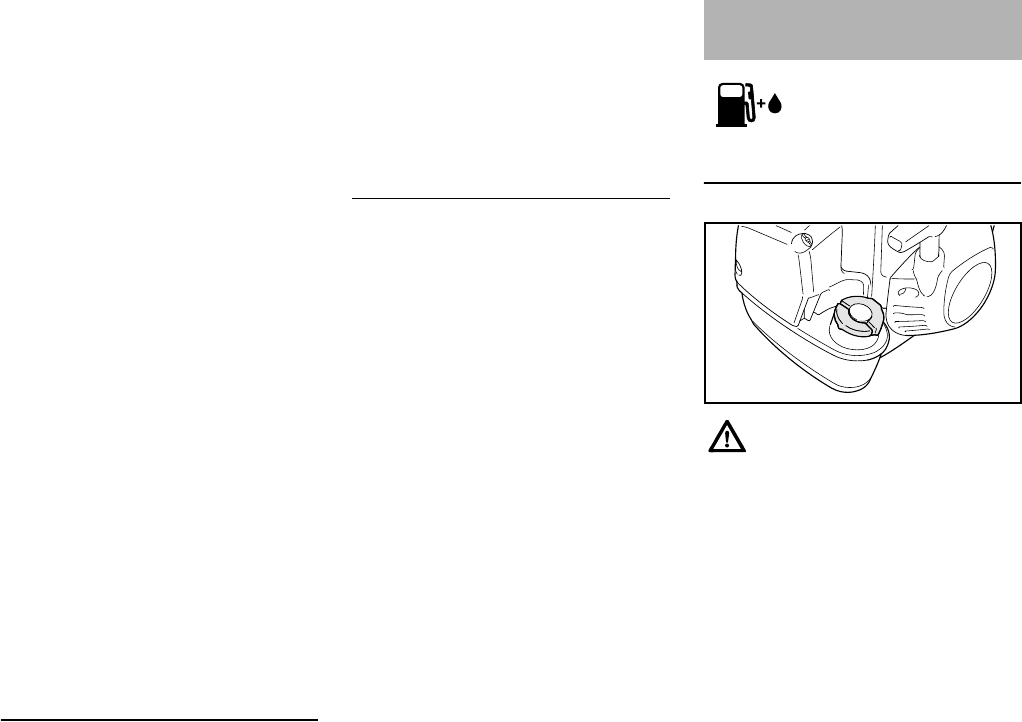
FS 260 C, FS 360 C
español / EE.UU
81
Recomendamos el aceite STIHL para
motores de dos tiempos 50:1 pues está
especialmente formulado para usarse
en motores STIHL.
No use aceites para mezclar con
designaciones BIA o TCW (para
motores de dos tiempos enfriados por
agua) ni otros aceites para mezclar
diseñados para usar en motores
enfriados por agua o por aire (por
ejemplo, en motores marinos fuera de
borda, motonieves, motosierras,
bicimotos, etc.).
Manipule la gasolina con sumo cuidado.
Evite el contacto directo con la piel y
evite inhalar los vapores de
combustible. Cuando se reabastece de
combustible, quite primero el envase del
vehículo y colóquelo en el suelo antes
de llenarlo. No llene un envase que está
en un vehículo o apoyado sobre el
mismo.
Mantenga el envase bien cerrado para
evitar la entrada de humedad a la
mezcla.
Según sea necesario, limpie el tanque
de combustible de la máquina y el
envase en que se guarda la mezcla de
combustible.
Duración de la mezcla de
combustible
Mezcle una cantidad suficiente de
combustible para trabajar unos pocos
días, no lo guarde por más de 3 meses.
Guárdelo únicamente en envases
aprobados para combustible. Para el
proceso de mezclado, vierta el aceite en
el envase primero y luego agregue la
gasolina. Cierre el envase y agítelo
vigorosamente a mano para asegurar
que se mezclen bien el aceite y la
gasolina.
Deseche los envases vacíos usados
para mezclar el aceite únicamente en
vertederos autorizados para ello.
Preparaciones
NSobre suelo nivelado, coloque la
máquina de modo que la tapa de
llenado quede orientada hacia
arriba.
NAntes de llenar la máquina con
combustible, limpie a fondo la tapa
de llenado y la zona alrededor del
mismo para evitar la entrada de
tierra al tanque.
Siempre agite bien la mezcla en el
recipiente antes de llenar la máquina
con combustible.
Gaso-
lina
Aceite (STIHL 50:1 ó aceite
de alta calidad equivalente)
gal
EE.UU.
oz fl
EE.UU.
12.6
2 1/2 6.4
512.8
Llenado de combustible
Cuando se abastece el
combustible a la máquina cuando
está sobre una pendiente,
coloque la máquina de modo que
la tapa de llenado quede cuesta
arriba.
9926BA005 KN
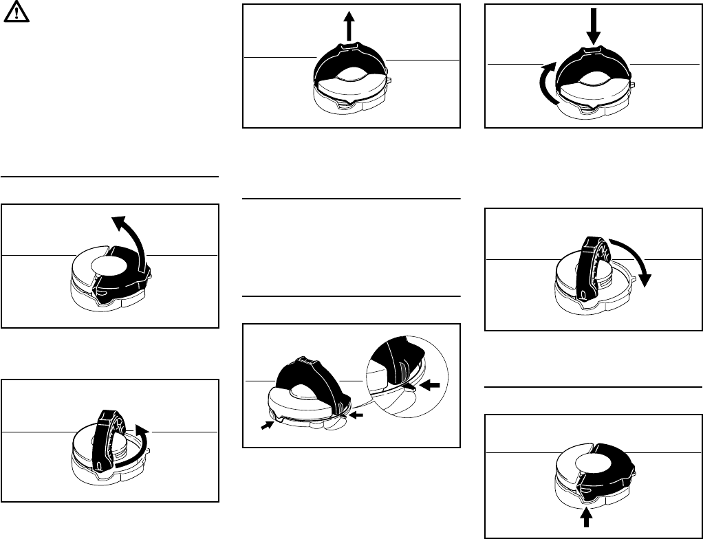
FS 260 C, FS 360 C
español / EE.UU
82
Apertura
NLevante el mango hasta que esté
vertical.
NGire la tapa en sentido
contrahorario (aprox. 1/4 de vuelta).
NQuite la tapa de llenado de
combustible.
Carga de combustible
Tenga cuidado de no derramar el
combustible y no llene en exceso el
tanque.
Cierre
Con el mango vertical:
NInserte la tapa – las marcas de
colocación en la tapa y el tanque de
combustible deben estar alineados.
NLa tapa debe caer por completo en
la abertura en esta posición.
NMientras presiona la tapa hacia
abajo, gírela con firmeza en sentido
horario hasta que haga tope
(aprox. 1/4 de vuelta).
NPliegue el mango.
Comprobación del cierre apropiado
NEl tope en el mango debe encajar
completamente en el rebajo
(flecha), y el mango debe quedar
totalmente a ras con respecto a la
parte superior de la tapa.
Para reducir el riesgo de
quemaduras, así como otras
lesiones corporales ocasionadas
por los escapes de vapor de
gasolina y otras emanaciones,
quite la tapa de llenado de
combustible cuidadosamente de
modo que la presión que se
pueda haber acumulado en el
tanque se disipe lentamente.
001BA218 KN
001BA219 KN
001BA224 KN
001BA220 KN
001BA221 KN
001BA222 KN
001BA223 KN
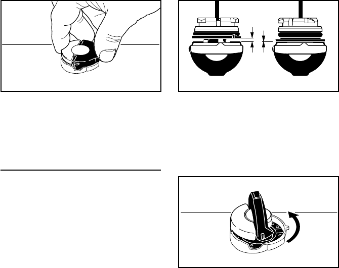
FS 260 C, FS 360 C
español / EE.UU
83
NAgarre la tapa y revise el apriete.
NSi puede moverla, no está instalada
de manera apropiada.
Alineación incorrecta de las piezas
de la tapa
NSi la tapa no cae completamente en
la abertura cuando las marcas de
colocación están alineadas y/o la
tapa no se ajusta de manera
adecuada al girarla, la base de la
tapa puede rotar hasta salir de
posición con respecto a la parte
superior.
NEl manejo, la limpieza o un intento
de apriete incorrecto pueden
ocasionar una alineación
incorrecta.
NPara corregir una alineación
incorrecta, gire la tapa (con el
mango hacia arriba) hasta que
caiga por completo en la abertura
del tanque.
NGire la tapa en sentido
contrahorario hasta que haga tope
(aprox. 1/4 de vuelta) – esto girará
la base de la tapa a la posición
correcta.
NGire la tapa en sentido horario,
cerrándola normalmente – vea las
secciones "Cierre" y
"Comprobación del cierre
apropiado".
NSi la tapa sigue sin ajustarse
apropiadamente, podría estar
dañada o rota; deje de utilizar la
unidad de inmediato y llévela a su
concesionario autorizado de STIHL
para que la reparen.
001BA225 KN
A
izquierd
a:
Base de la tapa alineada de
manera inapropiada (con
espacio abierto)
A
derecha:
Base de la tapa colocada de
manera correcta para la
instalación
001BA227 KN
001BA226 KN
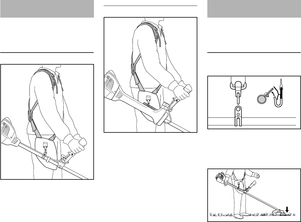
FS 260 C, FS 360 C
español / EE.UU
84
La instalación del arnés completo se
describe en forma detallada en la hoja
de instrucciones suministrada.
FS 260 C
NPóngase el arnés completo (1).
NAjuste el largo de la correa de modo
que el mosquetón (2) quede
aproximadamente el ancho de la
mano por debajo de su cadera
derecha.
NEquilibre la máquina – consulte
"Equilibrio de la máquina".
FS 360 C
NPóngase el arnés completo (1).
NAjuste el largo de la correa de modo
que el mosquetón (2) quede
aproximadamente el ancho de la
mano por debajo de su cadera
derecha.
NConecte el gancho de resorte a la
pletina perforada (3) de la máquina.
Encuentre el punto de conexión correcto
para el accesorio de corte específico –
vea la sección "Equilibrio de la
máquina".
El tipo y la versión del arnés y gancho
con resorte dependen del lugar de
venta.
FS 260 C
Conexión de la máquina al arnés
NEnganche el gancho de resorte (1)
en la argolla (2) ubicada en el tubo
de mando
Posiciones de suspensión
Las cabezas de segado, la cuchillas
para pasto y las cuchillas para
matorrales deben quedar ligeramente
apoyadas en el suelo.
Colocación del arnés
completo
002BA386 KN
1
2
3
002BA411 KN
1
2
Equilibro de la unidad
1
2
1
2
002BA387 KN
002BA388 KN
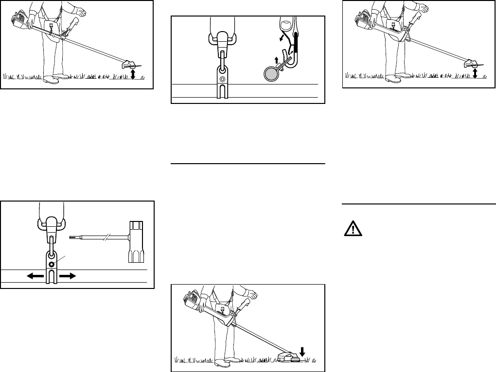
FS 260 C, FS 360 C
español / EE.UU
85
Las cuchillas circulares deben quedar
"flotando" a unos 20 cm (8 pulg) sobre el
suelo.
Lleve a cabo los pasos dados a
continuación para obtener la posición de
colgado:
Deje la máquina oscilar hasta que se
detenga
NDestornille el tornillo (3)
NAjuste la argolla de transporte (2) –
apriete el tornillo levemente –
permita que la máquina oscile hasta
que se detenga – revise la posición
de colgado
Una vez que se ha obtenido la posición
de colgado correcta:
NApriete el tornillo en la argolla de
transporte
Desconexión de la máquina del arnés
NPulse el resorte en el gancho (1) y
quite la argolla de transporte (2) del
gancho
FS 360 C
La máquina se equilibra de forma
diferente, dependiendo del accesorio de
corte montado.
NDeje que la máquina cuelgue en el
arnés hasta que la misma se pare –
cambie el punto de conexión, de ser
necesario
Posiciones de suspensión
Las cabezas de segado, la cuchillas
para pasto y las cuchillas para
matorrales deben quedar ligeramente
apoyadas en el suelo.
Las cuchillas circulares deben quedar
"flotando" a unos 20 cm (8 pulg) sobre el
suelo.
Desconexión de la máquina del arnés
NComprima el resorte del gancho y
saque la tira perforada del gancho
Retiro rápido de la máquina en caso
de emergencia
002BA389 KN
3
2
002BA390 KN
1
2
1
2
002BA391 KN
6BA009 KN
Tan pronto como se hace
evidente que una situación
peligrosa se está desarrollando, la
máquina debe ponerse en el
suelo rápidamente. Para poner la
máquina rápidamente en el suelo,
efectuar el procedimiento descrito
en "Desconexión de la máquina
del arnés". Practique la puesta en
el suelo rápida de la máquina.
Para evitar daños, no tire la
máquina al suelo al practicar el
procedimiento.
6BA010 KN
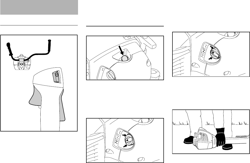
FS 260 C, FS 360 C
español / EE.UU
86
Controles
1Bloqueo de gatillo de aceleración
2Gatillo de aceleración
3Interruptor de parada con
posiciones Run (Marcha) y Stop
(Parada). Pulse el interruptor de
parada (STOP) para apagar el
encendido.
Funcionamiento del interruptor de
parada y sistema de encendido
El interruptor de parada normalmente
está en la posición de Marcha: En esta
posición el encendido está conectado –
el motor está listo para arrancar y puede
arrancarse. El encendido se apaga al
pulsar el interruptor de parada. El
sistema de encendido se vuelve a
conectar después que el motor deje de
girar.
Arranque del motor
NOprima el bulbo (4) de la bomba de
combustible por lo menos cinco
veces, aunque el bulbo esté lleno
de combustible.
Motor frío (arranque en frío)
NPulse hacia adentro el borde
exterior (flechas) de la perilla del
estrangulador(5) y gírelo a g.
También utilice esta posición si el motor
ha estado en marcha, pero todavía se
encuentra frío.
Motor caliente (arranque en caliente)
El motor ha alcanzado su temperatura
de funcionamiento normal, luego se
para y se vuelve a arrancar después de
transcurridos más de 5 minutos.
NPulse hacia adentro el borde
exterior (flechas) de la perilla del
estrangulador(5) y gírelo a <.
Arranque
NColoque la máquina sobre el suelo:
Debe quedar firmemente apoyada
en la placa protectora del motor y el
Arranque / parada del
motor
1
002BA392 KN
2
3
4
9926BA006 KN
5
9926BA007 KN
5
9926BA008 KN
5
6BA011 KN
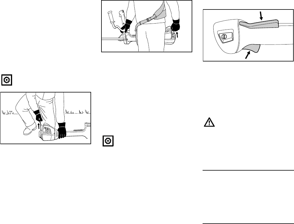
FS 260 C, FS 360 C
español / EE.UU
87
deflector. Verifique que el accesorio
de corte no esté tocando el suelo ni
ningún otro obstáculo.
NAsegúrese de tener los pies bien
apoyados – ya sea de estar a pie,
agacharse o arrodillarse.
NSujete la máquina firmemente en
el suelo usando la mano izquierda y
empujando hacia abajo – no toque
el gatillo de aceleración ni la
palanca de bloqueo.
NSujete el mango de arranque con la
mano derecha.
Método alternativo de arranque:
Motor tibio y máquina colgando del
arnés.
NAgarre la máquina firmemente con
la mano derecha en el tubo de
mando, el soporte del mango o el
manillar.
NCon máquina detrás de su cuerpo,
empújela contra el costado
izquierdo de su cuerpo.
NSujete el mango de arranque con la
mano izquierda.
NTire uniformemente del mango de
arranque.
NNo deje que el mango de arranque
salte bruscamente hacia atrás.
Guíelo lentamente hacia el interior
de la caja para que la cuerda de
arranque se enrolle correctamente.
NContinúe haciendo girar el motor
hasta que arranque.
Tan pronto arranca
NEmpuje el bloqueo del gatillo de
aceleración hacia abajo y abra el
acelerador – la palanca del
estrangulador se mueve a la
posición de marcha F. Después de
un arranque en frío, caliente el
motor accionando varias veces el
acelerador.
Su máquina está lista para trabajar.
Parada del motor
NAccione el interruptor de parada – el
motor se para – suelte el interruptor
de parada – el mismo salta a la
posición de marcha.
Sugerencias adicionales para el
arranque
A temperaturas ambiente muy bajas
NAjuste el motor para las
operaciones de invierno, de ser
necesario; vea "Manejo durante el
invierno".
No se pare ni se arrodille sobre el
tubo de mando.
6BA012 KN
No tire de la cuerda de arranque
totalmente hasta fuera, se podría
romper.
6BA013 KN
Asegúrese de que el carburador
esté correctamente ajustado. El
accesorio de corte no debe girar
cuando el motor está funcionando
a marcha en vacío.
6BA014 KN

FS 260 C, FS 360 C
español / EE.UU
88
El motor se cala en la posición de
arranque en frío g o durante la
aceleración
NMueva la palanca del estrangulador
a < y continúe haciendo girar el
motor hasta que arranque.
El motor no arranca en la posición de
arranque en caliente <
NMueva la palanca del estrangulador
a g y continúe haciendo girar el
motor hasta que arranque.
Si el motor no arranca
NCompruebe que todos los ajustes
sean correctos.
NVerifique que haya combustible en
el tanque y agregue combustible de
ser necesario.
NVerifique que el casquillo de la bujía
esté correctamente conectado.
NRepita el procedimiento de
arranque.
Se agotó completamente el
combustible en el tanque
NDespués de llenar el tanque, oprima
el bulbo de la bomba de
combustible por lo menos cinco
veces, aunque el bulbo esté lleno
de combustible.
NAjuste la palanca del estrangulador
según la temperatura del motor.
NArranque el motor.
Durante el período de rodaje
Una máquina nueva de fábrica no debe
hacerse funcionar a velocidad alta
(aceleración máxima sin carga) por el
lapso que tome llenar el tanque tres
veces. Esto evita la imposición de
cargas innecesariamente altas durante
el período de rodaje. Ya que todas las
piezas móviles deben asentarse
durante el período de rodaje inicial,
durante este tiempo la resistencia
causada por fricción en el motor es más
elevada. El motor desarrolla su potencia
máxima después de haber llenado el
tanque de 5 a 15 veces.
Durante el trabajo
Después de un período largo de
funcionamiento con el acelerador a
fondo, deje funcionar el motor por un
rato en ralentí de modo que el calor en
el motor sea disipado por la corriente de
aire de enfriamiento. Esto ayuda a evitar
que los componentes montados en el
motor (encendido, carburador) sufran
sobrecargas térmicas.
Después de terminar el trabajo
Almacenamiento por corto tiempo:
Espere hasta que el motor se enfríe.
Vacíe el tanque de combustible y
guarde la máquina en un lugar seco,
alejada de fuentes de encendido, hasta
que la vuelva a utilizar. Para los
intervalos de almacenamiento por
tiempo prolongado – vea
"Almacenamiento de la máquina".
Instrucciones para el uso
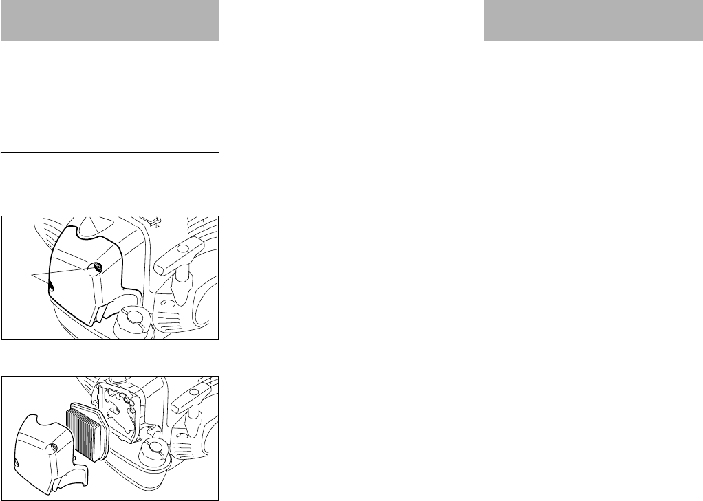
FS 260 C, FS 360 C
español / EE.UU
89
La suciedad en el filtro de aire reduce la
potencia del motor, aumenta el
consumo de combustible y dificulta el
arranque del motor.
Si se nota una pérdida considerable
de la potencia del motor
NPonga la palanca del estrangulador
en g.
NAfloje los tornillos (1).
NQuite la cubierta del filtro (2).
NQuite la tierra suelta de alrededor
del elemento de filtro (3) y del
interior de la cubierta de filtro.
El filtro (3) consta de un elemento de
papel con pliegues.
NQuite y revise el elemento de
filtro (3) – sustitúyalo si está sucio o
dañado.
NInstale el filtro en la caja de filtro.
NInstalación de la cubierta del filtro
Máquinas con el "juego de placa de
cierre" para invierno
El filtro (3) consta de un elemento de
tela sintética, vea también "Manejo
durante el invierno".
NGolpee el filtro (3) en la palma de la
mano o sóplelo con aire comprimido
de adentro hacia afuera.
En caso de suciedad difícil o tela de filtro
pegajosa:
NLave el filtro en una solución limpia
y no inflamable (por ejemplo, agua
jabonosa tibia) y séquelo.
Un filtro dañado siempre debe
sustituirse.
Las emisiones de gases de escape son
controladas por el diseño de parámetros
y componentes fundamentales del
motor (por ej. carburación, encendido,
regulación y regulación de las válvulas o
la lumbrera) sin la adición de ningún
equipo importante.
Limpieza del filtro de aire
9926BA013 KN
1
3
9926BA014 KN
2
Gestión del motor
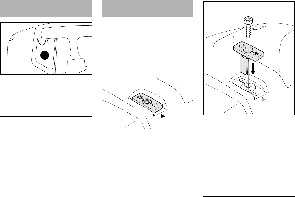
FS 260 C, FS 360 C
español / EE.UU
90
El carburador se ajusta en fábrica para
garantizar que la mezcla de
combustible/aire sea óptima bajo la
mayoría de las condiciones de trabajo.
Ajuste de marcha en vacío
El motor se para cuando funciona a
ralentí
NGire el tornillo de ajuste de marcha
en vacío (LA) lentamente en
sentido horario hasta que el motor
funcione de modo suave.
La herramienta de corte gira cuando
el motor funciona a ralentí
NGire el tornillo de ralentí (LA)
lentamente en sentido
contrahorario hasta que el
accesorio de corte deje de
moverse.
A temperaturas bajo +10 °C (+50 °F)
Precalentamiento del carburador
Si se mueve el obturador, se aspira aire
caliente de alrededor del cilindro y se lo
mezcla con el aire frío para evitar el
congelamiento del carburador.
La flecha en la envuelta (1) muestra la
posición del obturador (2) para trabajo
en verano y en invierno. Clave de los
símbolos:
–Símbolo "Sol" = funcionamiento de
verano
–Símbolo "Copo de nieve" =
funcionamiento de invierno
NDesenrosque y saque el tornillo (3)
del obturador.
NQuite el obturador (2) de la envuelta
NGire el obturador (2) de la posición
de verano a la de invierno y vuélvalo
a insertar
NEnrosque el tornillo (3) a través del
obturador en la envuelta
A temperaturas entre +10 °C (+50 °F)
y +20 °C (+70 °F)
En esta gama de temperatura, la
máquina puede utilizarse de modo
normal con el obturador (2) en posición
de verano. Cambie la posición del
obturador según sea necesario.
Ajuste del carburador
9926BA015 KN
HL
LA
Manejo durante el invierno
2
1
9926BA016 KN
2
9926BA017 KN
3
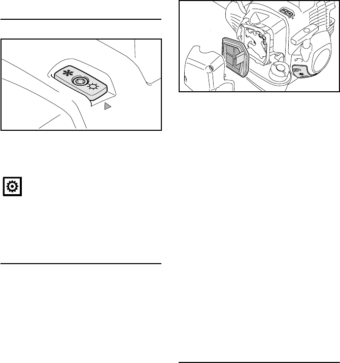
FS 260 C, FS 360 C
español / EE.UU
91
A temperaturas de más de +20 °C
(+70 °F):
NSiempre vuelva a colocar el
obturador (2) en la posición de
verano
A temperaturas bajo 10 °C (+14 °F)
En condiciones de invierno extremo,
cuando existen las condiciones
siguientes
–A temperaturas bajo 10 °C (+14 °F)
–Nieve pulverizada o amontonada
se recomienda usar el "juego de placa
de tapa", disponible como accesorio
especial.
El "juego de placa de tapa" contiene las
piezas siguientes para cubrir la
máquina:
4Placa para tapar parcialmente las
rendijas de la caja del arrancador
5Inserto de tela y plástico para el
filtro de aire
–Anillo "O" para la tapa de llenado
–Hoja de información que describe la
conversión de la máquina
Después de haber instalado el juego de
placa de tapa:
NFije el obturador (2) en posición de
invierno
NSi la motosierra está muy fría
(formación de escarcha) – después
de arrancarla, caliente el motor a
una velocidad más alta (el
accesorio de corte gira)
A temperaturas bajo 10 °C (+14 °F)
NRevertir la máquina, sustituyendo
las piezas del "juego de placa de
tapa" con las piezas para
funcionamiento en verano
El anillo "O" que se instala en la tapa de
llenado con el "juego de placa de tapa"
puede dejarse instalado en la máquina.
Según la temperatura ambiente:
NFije el obturador (2) en posición de
verano o de invierno
No utilice la máquina en modo de
invierno a temperaturas
superiores a los +20 °C (+70 °F),
ya que con ello se corre el riesgo
de causarle daños al motor por
sobrecalentamiento.
2
9926BA018 KN
4
5
9926BA019 KN
2
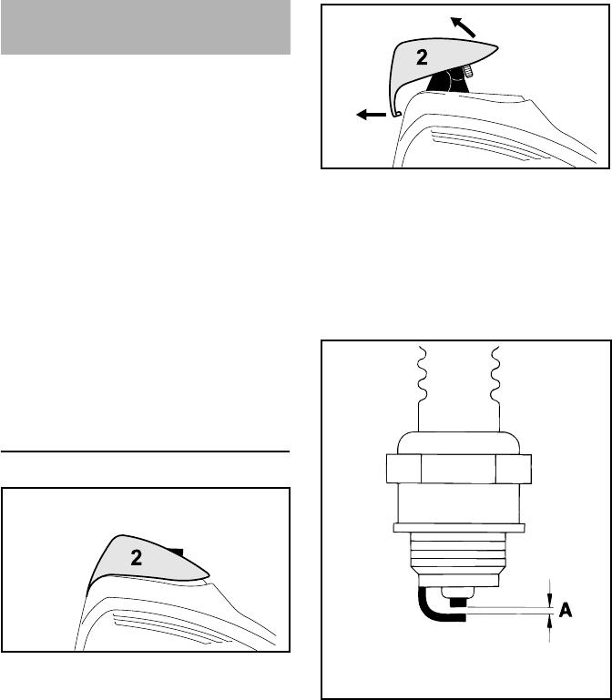
FS 260 C, FS 360 C
español / EE.UU
92
Si el motor pierde potencia, es difícil
arrancarlo o funciona de modo irregular
a ralentí, revise la bujía primero.
Instale una bujía nueva después de
aprox. 100 horas de funcionamiento,
o más temprano si los electrodos están
muy gastados.
Si la mezcla del combustible es
incorrecta (demasiado aceite en la
gasolina), el filtro de aire está sucio, y
las condiciones de trabajo no son
favorables (especialmente a
aceleraciones intermedias) se afecta la
condición de la bujía. Estos factores
permiten la formación de depósitos en la
punta aislante, los cuales pueden
perjudicar el rendimiento.
Retiro de la bujía
NGire el tornillo (1) en la tapa (2)
hasta que la cabeza del tornillo
sobresalga de la tapa.
NLevante la parte delantera de la
tapa (2) y empújela hacia atrás para
desengancharla.
NDeje la tapa a un lado.
NQuite el casquillo de la bujía (3).
NDestornille la bujía.
Si la mezcla del combustible es
incorrecta (demasiado aceite en la
gasolina), el filtro de aire está sucio, y
las condiciones de trabajo no son
favorables (especialmente a
aceleraciones intermedias) se afecta la
condición de la bujía. Estos factores
permiten la formación de depósitos en la
punta aislante, los cuales pueden
perjudicar el rendimiento.
Si el motor pierde potencia, es difícil
arrancarlo o funciona de modo irregular
a ralentí, revise la bujía primero.
NSaque la bujía – vea
"Arranque/parada del motor".
NLimpie la bujía si está sucia.
NRevise la separación entre
electrodos (A) y ajústela de ser
necesario – vea "Especificaciones".
NUtilice únicamente bujías tipo
resistencia cuyo margen de
rendimiento sea el aprobado.
Corrija los problemas que hayan
causado la contaminación de la bujía:
NDemasiado aceite en la mezcla de
combustible.
NFiltro de aire sucio.
NCondiciones desfavorables de
funcionamiento, por ejemplo,
funcionando bajo carga parcial.
Instale una bujía nueva después de
aprox. 100 horas de funcionamiento,
o más temprano si los electrodos están
muy gastados.
Bujía
1
9926BA020 KN
3
9926BA021 KN
000BA002 KN
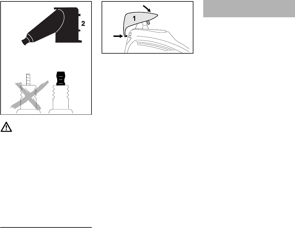
FS 260 C, FS 360 C
español / EE.UU
93
Instalación de la bujía
NAtornille la bujía en el cilindro.
NPresione el casquillo firmemente
sobre la bujía
NColoque la tapa (1) en la envuelta
por la parte trasera y empuje la
orejeta (2) dentro de la abertura (3)
de la envuelta al mismo tiempo.
NGire la tapa hacia delante sobre la
envuelta, e inserte y apriete el
tornillo (4) firmemente.
Si el funcionamiento del motor es
insatisfactorio aunque el filtro de aire
está limpio y el carburador y el cable del
acelerador han sido debidamente
ajustados, la causa puede hallarse en el
silenciador.
Solicite al concesionario que revise si
hay contaminación (coquización) en el
silenciador.
STIHL recomienda que un
concesionario STIHL autorizado efectúe
los trabajos de mantenimiento y
reparación.
Advertencia!
Para reducir el riesgo de incendio y de
quemaduras, utilice solamente las
bujías autorizadas por STIHL. Siempre
empuje el casquillo (2) de la bujía firme-
mente en el borne (1) del tamaño
adecuado. (Nota: Si el borne tiene una
tuerca adaptadora SAE desmontable,
tiene que ser instalada.) Una conexión
suelta entre el casquillo de la bujía y el
conector del cable de encendido en el
casquillo puede crear un arco voltaico y
encender los vapores del combustible,
provocando un incendio.
0
00BA036 TR
1
4
3
2
9926BA022 KN
Funcionamiento del motor
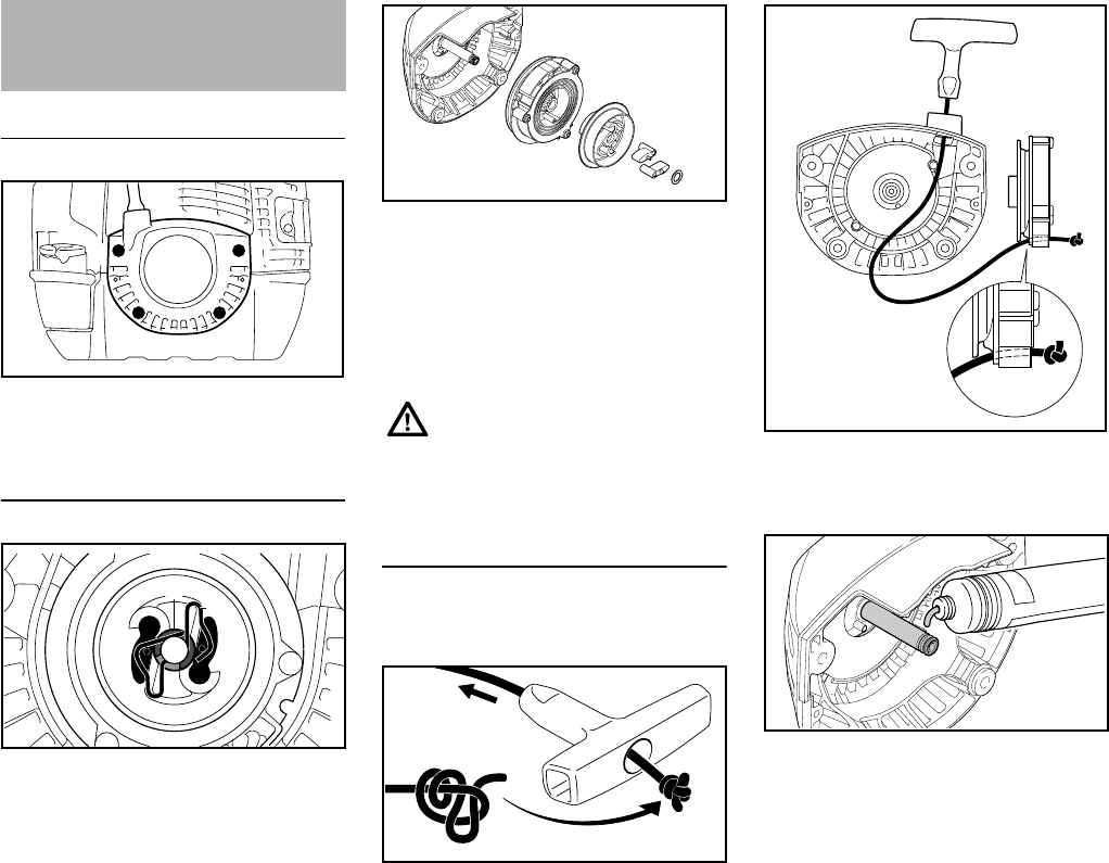
FS 260 C, FS 360 C
español / EE.UU
94
Retiro del arrancador
NSaque los tornillos (1).
NLevante el arrancador para quitarlo.
Retiro del rotor de la cuerda
NUse un destornillador o alicates
adecuados para retirar
cuidadosamente la pinza de
resorte (2) del poste del arrancador.
NSaque la pinza en E (3)
cuidadosamente.
NRetire cuidadosamente el rotor de
cuerda (4) con su portador (5),
trinquetes (6) y arandela (7).
NColocar el portador (5) hacia abajo,
de manera que los trinquetes y la
arandela no puedan caerse de su
lugar.
Sustitución de una cuerda de
arranque rota
NQuite el resto de la cuerda del rotor
y del mango de arranque.
NPase la cuerda nueva por el mango
de arranque y haga uno de los
nudos ilustrados.
NTire del nudo de vuelta en el mango.
NMeter la cuerda por la parte superior
del buje guía (1) y el rotor de la
cuerda (2).
NCubrir el poste del arrancador de
modo uniforme con lubricante para
engranajes STIHL – ver
"Accesorios especiales".
NDeslice el rotor de la cuerda con el
portador, trinquetes y arandela
sobre el poste del arrancador.
Gírelo hacia uno y otro lado para
engranar la espiral terminal del
resorte de rebobinado.
Sustitución de la cuerda de
arranque y del resorte de
rebobinado
1 1
1 1
9926BA023 KN
32
9926BA024 KN
El resorte de rebobinado puede
saltarse y desenrollarse durante
esta operación – tome medidas
para evitar lesiones.
5
6
9926BA025 KN
4
7
9926BA026 KN
1
9926BA027 KN
2
9926BA035 KN
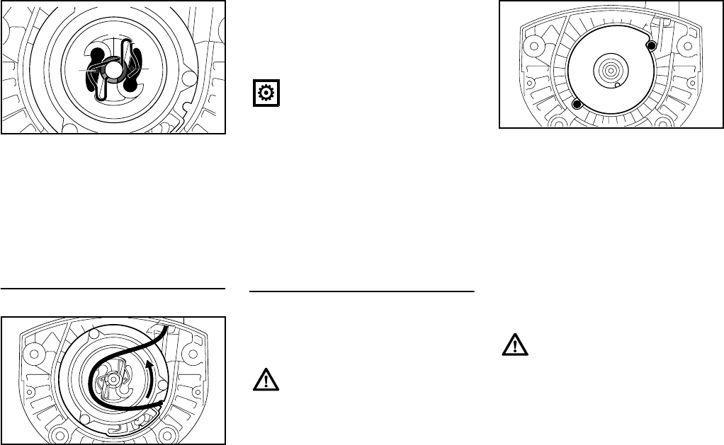
FS 260 C, FS 360 C
español / EE.UU
95
NColoque la pinza en E (3) en la
ranura del poste del arrancador.
NEmpuje la pinza de resorte (4) en su
lugar – debe apuntar en sentido
contrahorario, tal como se muestra,
y debe encajarse en las espigas de
los trinquetes (5).
Tensado del resorte de rebobinado
NForme un bucle con la cuerda de
arranque sin envolver y utilícelo
para girar el rotor seis revoluciones
completas en sentido contrahorario.
NSujete firmemente el rotor.
NTire y enderece la cuerda torcida.
NSuelte el rotor de la cuerda.
NSuelte lentamente la cuerda para
que se enrolle en el rotor.
El mango de arranque debe quedar
firmemente en el buje para la cuerda. Si
el mango cae hacia un lado: Déle una
vuelta adicional al rotor de la cuerda
para aumentar la tensión del resorte.
NQuítele una vuelta de la cuerda al
rotor.
NInstale el arrancador con cuerda.
Sustitución de un resorte de
rebobinado roto
NQuite el rotor de la cuerda de la
forma descrita en "Retiro de la
cuerda del rotor".
NSaque los tornillos (1).
NRetire la caja de resorte y las piezas
del resorte
NLubrique el resorte de repuesto
nuevo listo para instalar en la caja
nueva con unas cuantas gotas de
aceite sin resina – vea "Accesorios
especiales".
NColoque el resorte de repuesto con
la caja – la placa inferior debe
quedar orientada hacia arriba.
NInstale los tornillos.
NInstale el rotor de la cuerda de la
manera descrita en "Sustitución de
un resorte de rebobinado roto".
NAplique tensión al resorte de
rebobinado de la manera descrita
en "Tensión del resorte de
rebobinado".
NInstale el arrancador con cuerda.
34
9926BA028 KN
55
9926BA029 KN
Cuando la cuerda de arranque se
extiende completamente, debe
ser posible girar el rotor una
vuelta completa adicional. En
caso contrario, el resorte está
sobretensado y podría
romperse:
Las partes del resorte aún pueden
estar bajo tensión y podrían
desprenderse al quitar el rotor de
la cuerda y la caja del resorte.
Para reducir el riesgo de
lesionarse, póngase un protector
facial y guantes gruesos.
Si el resorte se sale de la caja
durante la instalación: Usar una
careta protectora y guantes de
trabajo al colocar el resorte en su
caja – en sentido horario –
avanzando del lado exterior al
interior.
1
9926BA030 KN
1
FS 260 C, FS 360 C
español / EE.UU
96
Para intervalos de 3 meses o más
NVacíe y limpie el tanque de
combustible en una zona bien
ventilada.
NDeseche el combustible de acuerdo
con los requerimientos locales de
protección del medio ambiente.
NHaga funcionar el motor hasta que
el carburador se seque. Esto ayuda
a evitar que los diafragmas del
carburador se peguen.
NRetire, limpie e inspeccione el
accesorio de corte.
NLimpie la máquina a fondo - preste
atención especial a las aletas del
cilindro y al filtro de aire.
NGuarde la máquina en un lugar seco
y bajo llave, fuera del alcance de los
niños y de otras personas no
autorizadas.
NUse una lima (accesorio especial)
para afilar los accesorios de corte
romos. En el caso de desgaste o
mellas más serios: Vuelva a afilar
con una rectificadora o pida que el
trabajo se lo haga el concesionario
– STIHL recomienda acudir a un
concesionario de STIHL.
NAfile frecuentemente, quitando la
menor cantidad posible de material;
por lo general dos o tres pasadas de
la lima son suficientes.
NAfile las cuchillas (1)
uniformemente – no altere de
manera alguna el contorno de la
cuchilla matriz (2).
Vea las instrucciones en el embalaje del
accesorio de corte para información
adicional acerca del afilado.
Equilibrio
NDespués de aproximadamente 5
afiladas, revise la cuchilla con un
equilibrador STIHL (accesorio
especial) – o pida que un
concesionario la revise y vuelva a
ajustar el equilibrio según sea
necesario – STIHL recomienda
acudir a un concesionario STIHL
para servicio.
Almacenamiento de la
máquina Afilado de los accesorios
de corte
22
1
2
11
002BA042 KN
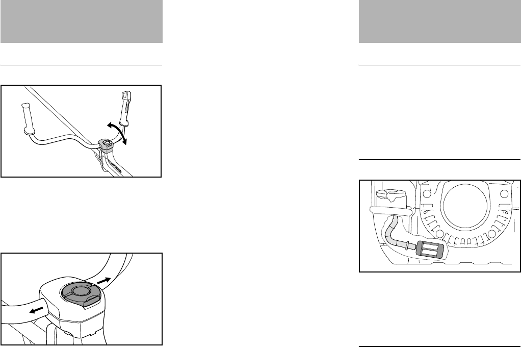
FS 260 C, FS 360 C
español / EE.UU
97
Zona fijada del mango
NVerifique la libertad de movimiento
del mango (1) en las pinzas
moldeadas (2) en intervalos
regulares.
Si el mango está rígido:
NSuelte el tornillo (3) de la pinza para
poder mover el mango.
NEmpuje el mango (1) en sentido
lateral para sacarlo de la pinza.
NUtilice un trapo humedecido con
una solución limpiadora no
inflamable fresca.
NLimpie completamente la zona
donde se sujeta el mango con el
trapo y la solución limpiadora.
NAlinee el mango y asegúrelo en su
posición con el tornillo de la pinza. Trabajos de mantenimiento
STIHL recomienda que un
concesionario STIHL autorizado efectúe
los trabajos de mantenimiento y
reparación.
Captador de combustible en el
tanque
NRevise anualmente el recogedor en
el tanque de combustible y pida que
el concesionario lo sustituye de ser
necesario.
Parachispas en el silenciador.
El parachispas no se usa en todos los
países
Inspección y
mantenimiento por el
usuario
1
2
6BA021 KN
3
6BA022 KN
1
Inspección y
mantenimiento por el
concesionario
9926BA031 KN
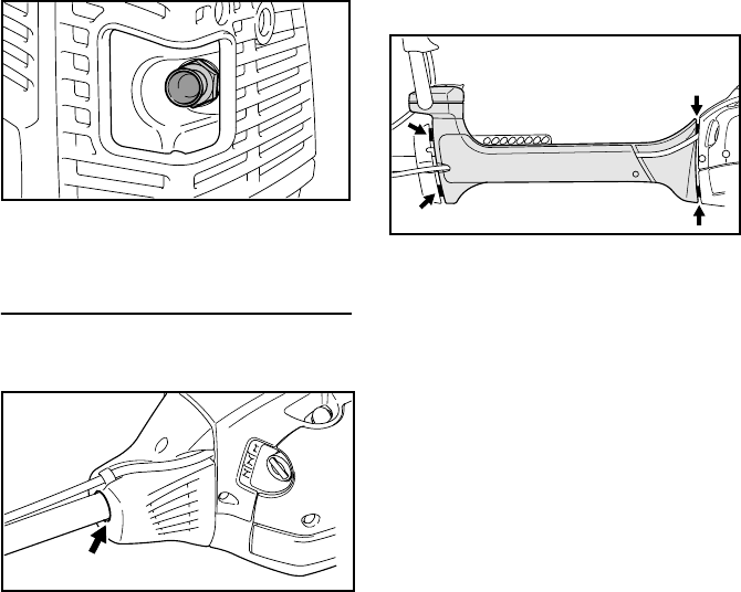
FS 260 C, FS 360 C
español / EE.UU
98
NSi el motor pierde potencia, haga
revisar el chispero del silenciador.
Elementos antivibración
FS 260 C
Se instala un elemento de caucho que
amortigua vibraciones entre el motor y el
tubo de mando. Revíselo si halla
señales de desgaste o si se percibe un
aumento notable en los niveles de
vibración.
FS 360 C
Entre el motor y el tubo de mando hay
instalados cuatro elementos
antivibración. Pida que el concesionario
revise el sistema si se observa un
aumento notable del nivel de
vibraciones.
9926BA032 KN
9926BA033 KN
6BA015 KN

FS 260 C, FS 360 C
español / EE.UU
99
Información para mantenimiento
Los intervalos dados a continuación corresponden únicamente a condiciones nor-
males de trabajo. Si el tiempo de trabajo por jornada es más largo que lo normal, o
si las condiciones son extremas (zonas polvorientas, etc.), acorte los intervalos indi-
cados de modo correspondiente.
antes de comenzar el trabajo
después de terminar el tra-
bajo o diariamente
después de cada parada
para cargar combustible
semanalmente
mensualmente
cada 12 meses
si hay problema
si tiene daños
si se requiere
Máquina completa
Inspección visual (condición general,
fugas) XX
Limpiar X
Mango de control Comprobar el funcionamiento XX
Filtro de aire
Limpiar XX
Reemplazar X
Recogedor en tanque de combustible
Revisar 1) X
Reemplazar1) XXX
Tanque de combustible Limpiar XXX
Carburador
Comprobar el ajuste de marcha en vacío
– el accesorio de corte no debe girar XX
Volver a ajustar la velocidad de marcha
en vacío X
Bujía
Ajustar la distancia entre electrodos X
Cambiar después de aprox. cada 100
horas de funcionamiento
Entradas de enfriamiento
Inspección visual X
Limpiar X
Parachispas en el silenciador.
Revisar 1) XX
Limpiar o reemplazar 1) X
Cámara de combustión
Descarbonizar después de las primeras
139 horas de funcionamiento, y luego
cada 150 horas
X
Todos los tornillos y tuercas accesibles
(salvo los tornillos de ajuste) Volver a apretar X
Elementos antivibración
Revisar XXX
Reemplazar1) X

FS 260 C, FS 360 C
español / EE.UU
100
Accesorio de corte
Inspección visual XX
Reemplazar X
Revisar el apriete XX
Accesorio de corte metálico Afilar XX
Etiquetas de seguridad Reemplazar X
1) STIHL recomienda que un concesionario de servicio STIHL efectúe este trabajo
Los intervalos dados a continuación corresponden únicamente a condiciones nor-
males de trabajo. Si el tiempo de trabajo por jornada es más largo que lo normal, o
si las condiciones son extremas (zonas polvorientas, etc.), acorte los intervalos indi-
cados de modo correspondiente.
antes de comenzar el trabajo
después de terminar el tra-
bajo o diariamente
después de cada parada
para cargar combustible
semanalmente
mensualmente
cada 12 meses
si hay problema
si tiene daños
si se requiere

FS 260 C, FS 360 C
español / EE.UU
101
1Tapa de llenado de combustible
2Tornillos de ajuste del carburador
3Mango de arranque
4Obturador
5Casquillo de bujía
6Silenciador con chispero
7Espaciador
8Placa protectora
9Gatillo de aceleración
10 Interruptor momentáneo de parada
11 Bloqueo de gatillo de aceleración
12 Manillar
13 Tornillo de fijación
14 Correa de transporte
15 Palanca del estrangulador
16 Bomba de combustible
17 Cubierta del filtro
18 Tanque de combustible
19 Argolla de transporte
20 Retenedor del cable del acelerador
21 Soporte del manillar
N.º Número de serie
Componentes importantes
13
12
20
18
5
4
2
1
15 17
3
9
10
11
14
19
21
6BA017 KN
#
816
21
FS 360
FS 260
7
6
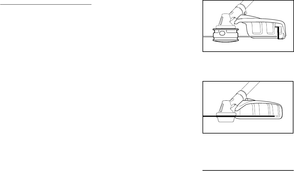
FS 260 C, FS 360 C
español / EE.UU
102
Definiciones
1 Tapa de llenado de combustible
Para tapar el tanque de
combustible.
2 Tornillos de ajuste del
carburador
Para afinar el carburador.
3 Mango de arranque
El mango del arrancador usado
para arrancar el motor.
4 Obturador
Con posiciones para invierno y
verano. El carburador se calienta en
la posición de invierno.
5 Casquillo de bujía
Conecta la bujía al alambre de
encendido.
6 Silenciador con chispero
El silenciador reduce los ruidos del
tubo de escape y desvía los gases
de escape lejos del operador.
El chispero está diseñado para
reducir el riesgo de incendios.
7Espaciador
Diseñado para reducir el riesgo de
quemaduras y incendios.
8 Placa protectora
Protege al tanque de combustible.
9 Gatillo de aceleración
Regula la velocidad del motor.
10 Interruptor momentáneo de
parada
Apaga el sistema de encendido del
motor y para el motor.
11 Bloqueo de gatillo de aceleración
Debe ser oprimido antes de poder
activar el gatillo de aceleración.
12 Manillar
Para agarrar con la mano para
manejar y controlar la máquina
durante los trabajos.
13 Tornillo de fijación
Bloquea el manillar en la posición
seleccionada.
14 Correa de transporte
Un dispositivo para conectar la
sierra despejadora al arnés.
15 Palanca del estrangulador
Facilita el arranque del motor al
enriquecer la mezcla.
16 Bomba de combustible
Suministra alimentación adicional
de combustible para el arranque en
frío.
17 Cubierta del filtro
Encierra y protege el filtro de aire.
18 Tanque de combustible
Contiene la mezcla de combustible
y aceite.
19 Argolla de transporte
Conecta la unidad al arnés.
20 Retenedor del cable del
acelerador
Sujeta el cable del acelerador al
tubo de mando.
21 Soporte del manillar
Conecta el eje y el manillar tipo
bicicleta.
1Cabeza segadora
2Deflector para cabezas segadoras
3Cuchilla limitadora del hilo
4Herramienta segadora metálica
5Deflector para las herramientas
segadoras metálicas
Definiciones
1 Cabeza segadora
El accesorio de corte, por ej. una
cabeza segadora, se usa para
diferentes propósitos.
2 Deflector para cabezas
segadoras
Sirve para reducir el riesgo de
lesiones causadas por objetos
extraños arrojados contra el
operador por el accesorio de corte y
por el contacto con el accesorio de
corte.
1
002BA412 KN
2
3
002BA417 KN
5
4
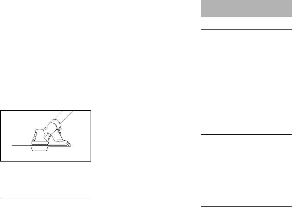
FS 260 C, FS 360 C
español / EE.UU
103
3 Cuchilla limitadora del hilo
Una cuchilla de metal en el deflector
para mantener el hilo de la cabeza
segadora al largo adecuado.
4 Herramienta segadora metálica
El accesorio de corte, por ejemplo la
cuchilla, hecho de metal para varios
propósitos.
5 Deflector para las herramientas
segadoras metálicas
Sirve para reducir el riesgo de
lesiones causadas por objetos
extraños arrojados contra el
operador por el accesorio de corte y
por el contacto con el accesorio de
corte.
6Cuchilla para sierra circular
7Tope limitador para sierras
circulares
Definiciones
6 Cuchilla para sierra circular
Un accesorio de corte hecho de
metal para cortar madera.
7 Tope limitador para sierras
circulares
Diseñado para colocar la cortadora
de matorrales firmemente contra la
madera para reducir el riesgo de
lesiones causadas por la pérdida de
control como resultado de las
fuerzas reactivas.
EPA / CEPA
El período de cumplimiento de
emisiones indicado en la etiqueta de
cumplimiento de emisiones es la
cantidad de horas de funcionamiento
para la cual la máquina ha demostrado
la conformidad con los requerimientos
de emisiones del Gobierno federal de
los EE.UU.
Categoría
CARB
El período de cumplimiento de
emisiones empleado en la etiqueta del
índice de aire CARB tiene las siguientes
definiciones:
Motor
Motor de un cilindro, dos tiempos
7
002BA435 KN
6
Especificaciones
A = 300 horas
B = 125 horas
C= 50horas
Extended = 300 horas
Intermediate = 125 horas
Moderate = 50 horas

FS 260 C, FS 360 C
español / EE.UU
104
FS 260 C
FS 360 C
Sistema de encendido
Encendido por magneto electrónico
Sistema de combustible
Carburador de diafragma de todas
posiciones con bomba de combustible
integral
Peso
Largo total
Comuníquese con su concesionario
STIHL para información acerca de
accesorios especiales que pueden estar
disponibles para su producto.
Cilindrada: 41,6 cm3
(2.54 pulg³)
Diámetro: 42 mm (1,65 pulg)
Carrera: 30 mm (1,18 pulg)
Potencia del motor
según ISO 8893:
2,0 kW (2,7 bhp) a
9000 rpm
Marcha en vacío: 2800 rpm
Velocidad de corte
(valor nominal): 12 500 rpm
Velocidad máx. de
eje de salida (acce-
sorio de corte) 8590 rpm
Cilindrada: 37,7 cm3)
(2,30 pulg³)
Diámetro: 40 mm (1,57 pulg)
Carrera: 30 mm (1,18 pulg)
Potencia del motor
según ISO 8893:
1,7 kW (2,3 bhp) a
8500 rpm
Marcha en vacío: 2800 rpm
Velocidad de corte
(valor nominal): 12 500 rpm
Velocidad máx. de
eje de salida (acce-
sorio de corte) 8590 rpm
Bujía (con
supresión): NGK CMR6H
Distancia entre
electrodos:
0,5 mm
(0,02 pulg)
Capacidad del tan-
que de
combustible:
FS 260 C 0,75 l (25,4 fl.oz)
FS 360 C 0,75 l (25,4 fl.oz)
seco, sin accesorio de corte y deflector
FS 260 C 7,9 kg (17,4 lb)
FS 360 C 8,5 kg (18,7 lb)
Sin accesorio de corte
FS 260 C 1685 mm
(66,34 pulg)
FS 360 C 1790 mm
(70,47 pulg)
Accesorios especiales

FS 260 C, FS 360 C
español / EE.UU
105
Los usuarios de esta máquina deben
efectuar únicamente los trabajos de
mantenimiento descritos en este
manual. Solamente los talleres
autorizados por STIHL deben llevar a
cabo los demás trabajos de reparación.
Los reclamos de garantía presentados
después de realizadas las reparaciones
serán aceptados únicamente si las
mismas fueron ejecutadas por un
concesionario de servicio autorizado
STIHL utilizando piezas de repuesto
originales de STIHL.
Es posible identificar las piezas
originales de STIHL por el número de
pieza STIHL, el logotipo de {
y, en ciertos casos, el símbolo K de
piezas STIHL. En las piezas pequeñas
el símbolo puede aparecer solo.
Asignación de declaraciones de
garantía de STIHL Incorporated acerca
del cumplimiento con los requerimientos
de emisiones de los modelos siguientes:
Declaración de garantía de STIHL
Incorporated sobre sistemas de control
de emisiones según normas Federales
–FS 260
Sus derechos y obligaciones de
garantía
La Agencia de Protección del Medio
Ambiente (EPA) de los EE.UU. y STIHL
Incorporated se complacen en
explicarle la garantía del sistema de
control de emisiones instalado en el
motor de su equipo. En los EE.UU., los
nuevos motores pequeños para equipos
de uso fuera de carretera modelos 1997
y posteriores deben estar diseñados,
construidos y equipados, al tiempo de la
venta, de conformidad con los
reglamentos de la EPA de los EE.UU.
para los motores pequeños de uso fuera
de carretera. El motor del equipo debe
carecer de defectos en el material y la
fabricación que puedan causar el
incumplimiento de las normas de la EPA
de los EE.UU. durante los primeros dos
años de uso del motor a partir de la
fecha de compra por el último
comprador.
STIHL Incorporated debe garantizar el
sistema de control de emisiones en el
motor pequeño para uso fuera de
carretera por el intervalo mencionado
más arriba, siempre que dicho motor no
haya estado sujeto a maltrato,
negligencia o cuidado inapropiado.
El sistema de control de emisiones de
su máquina incluye piezas tales como el
carburador y el sistema de encendido.
Información de reparación Asignación de
declaraciones de garantía
de STIHL Incorporated
Declaración de garantía de
STIHL Incorporated sobre
sistemas de control de
emisiones según normas
Federales

FS 260 C, FS 360 C
español / EE.UU
106
Además puede incluir mangueras,
conectores y otros conjuntos asociados
con el control de emisiones.
En los casos de existir una condición
amparada bajo garantía, STIHL
Incorporated reparará el motor pequeño
para equipo de uso fuera de carretera
sin costo alguno, incluido el diagnóstico
(si el trabajo de diagnóstico fue
realizado por un concesionario
autorizado), las piezas y la mano de
obra.
Cobertura de garantía del fabricante
En los EE.UU., los motores pequeños
para equipos de uso fuera de carretera
modelos 1997 y posteriores también
están garantizados por dos años. En el
caso de encontrarse defectos en
cualquiera de las piezas del motor
relacionadas con el sistema de control
de emisiones, la pieza será reparada o
sustituida por STIHL Incorporated sin
costo alguno.
Responsabilidades del usuario
relativas a la garantía
Como propietario de motor pequeño
para equipo de uso fuera de carretera,
usted tiene la responsabilidad de
realizar el mantenimiento requerido
descrito en su manual de instrucciones.
STIHL Incorporated le recomienda
guardar todos los recibos comprobantes
de los trabajos de mantenimiento
hechos a su motor pequeño para equipo
de uso fuera de carretera, pero STIHL
Incorporated no puede negar garantía
basado en el solo hecho de faltar los
recibos o del incumplimiento del
propietario de realizar todos los trabajos
de mantenimiento programados.
El uso de cualquier pieza de repuesto o
servicio cuyo comportamiento y
durabilidad sean equivalentes está
permitido en trabajos de mantenimiento
o reparación no contemplados en la
garantía, y no reducirá las obligaciones
de la garantía del fabricante del motor.
Sin embargo, como propietario del
motor pequeño para equipo de uso
fuera de carretera usted debe ser
consciente de que STIHL Incorporated
puede negarle cobertura de garantía si
dicho motor o una pieza del mismo ha
fallado debido a maltrato, descuido,
mantenimiento inadecuado o
modificaciones no autorizadas.
Usted es responsable de llevar el motor
pequeño para equipo de uso fuera de
carretera a un centro de servicio STIHL
tan pronto surja el problema. Las
reparaciones bajo garantía serán
realizadas en un tiempo razonable, sin
exceder de 30 días.
Ante cualquier duda respecto a sus
derechos y responsabilidades bajo esta
garantía, sírvase contactar al
representante de atención al cliente
STIHL llamando al 1-800-467-8445, o si
lo prefiere puede escribir a
STIHL Inc.,
536 Viking Drive, P.O. Box 2015,
Virginia Beach, VA 23450-2015 EE.UU.
www.stihlusa.com
Cobertura por STIHL Incorporated
STIHL Incorporated garantiza al último
comprador y a cada comprador
subsiguiente que el motor pequeño para
equipo de uso fuera de carretera está
diseñado, construido y equipado, al
tiempo de la venta, de conformidad con
todos los reglamentos aplicables.
Además, STIHL Incorporated garantiza
al comprador inicial y a cada comprador
subsiguiente que el motor está libre de
defectos en el material y fabricación que
puedan causar el incumplimiento de los
reglamentos aplicables durante un
período de dos años.
Período de garantía
El período de garantía comienza en la
fecha en que el motor del equipo
utilitario es entregado a usted y usted
firma y remite la tarjeta de garantía a
STIHL.
Si cualquier componente relacionado
con el sistema de control de emisiones
está defectuoso, el mismo será
sustituido por STIHL Incorporated sin
costo alguno para el propietario.
Cualquier pieza garantizada cuyo
reemplazo no está programado como
mantenimiento requerido, o que debe
recibir únicamente inspección regular
en el sentido de "reparar o sustituir
según sea necesario", estará
garantizada por el período de garantía.
Cualquier pieza cuyo reemplazo está
programado como mantenimiento
requerido estará garantizada por el
intervalo hasta el primer punto de
reemplazo programado para esa pieza.

FS 260 C, FS 360 C
español / EE.UU
107
Diagnóstico
Como propietario, a usted no se le debe
cobrar la mano de obra por los
diagnósticos que determinen que una
pieza garantizada está defectuosa. No
obstante, si usted reclama garantía para
un componente y se comprueba que la
máquina no está defectuosa, STIHL
Incorporated le cobrará el costo de la
prueba del sistema de control de
emisiones. El trabajo de diagnóstico
mecánico se realiza en un centro de
servicio autorizado por STIHL. La
prueba del sistema de control de
emisiones se realiza ya sea en la fábrica
de STIHL Incorporated o en un
laboratorio de ensayos independiente.
Trabajo bajo garantía
STIHL Incorporated reparará los
defectos amparados por la garantía en
cualquier estación de garantía o centro
de servicio autorizado por STIHL. Todo
trabajo de este tipo se hará gratis para el
propietario siempre que se determine
que la pieza cubierta por la garantía está
defectuosa.
Se puede usar cualquier pieza de
repuesto aprobada por el fabricante o
equivalente en las piezas relacionadas
con el sistema de control de emisiones,
y debe ser suministrada gratis al
propietario. STIHL Incorporated es
responsable por daños a otros
componentes del motor causados por la
falla de una pieza garantizada que
todavía está bajo garantía.
La lista siguiente define
específicamente las piezas
garantizadas y relacionadas con las
emisiones:
–Filtro de aire
–Carburador
–Bomba de combustible
–Estrangulador (sistema de refuerzo
para arranque en frío)
–Varillajes de control
–Múltiple de admisión
–Magneto o sistema de encendido
electrónico (módulo de encendido)
–Bujía
–Convertidor catalítico (si lo tiene)
–Tanque de combustible
–Tapa de tanque de combustible
–Línea de combustible
–Adaptadores de línea de
combustible
–Abrazaderas
–Sujetadores/pernos
Dónde presentar el reclamo para
servicio bajo garantía
Lleve el producto a cualquier centro de
servicio autorizado por STIHL y
presente la tarjeta de garantía firmada.
Requerimientos de mantenimiento
Las instrucciones presentadas en este
manual se basan en la aplicación de la
mezcla recomendada para motores de 2
tiempos (vea también la instrucción
"Combustible"). Las discrepancias de
estas recomendaciones con respecto a
la calidad y la proporción de la mezcla
de combustible y aceite pueden exigir
intervalos de mantenimiento más
cortos.
Limitaciones
Esta garantía de los sistemas de control
de emisiones no cubrirá ninguno de los
puntos siguientes:
Nreparación o sustitución requerida
debido a maltrato, negligencia o
falta del mantenimiento requerido,
Nreparaciones mal hechas o
sustituciones contrarias a las
especificaciones de STIHL
Incorporated que afecten
desfavorablemente el
funcionamiento y/o la durabilidad, y
las alteraciones o modificaciones
no recomendadas o aprobadas por
escrito por STIHL Incorporated,
y
Nla sustitución de piezas y otros
servicios y ajustes necesarios para
el mantenimiento requerido en y
después del primer punto de
reemplazo programado.

FS 260 C, FS 360 C
español / EE.UU
108
Asignación de declaraciones de
garantía de STIHL Incorporated acerca
del cumplimiento con los requerimientos
de emisiones de los modelos siguientes:
Declaración de garantía de STIHL
Incorporated sobre sistemas de control
de emisiones según normas Federales
–FS 360
Declaración de garantía de STIHL
Incorporated sobre el control de
emisiones de gases de escape y
emisiones por evaporación para el
Estado de California
–FS 360
No para California
Sus derechos y obligaciones de
garantía
La Agencia de Protección del Medio
Ambiente (EPA) de los EE.UU. y STIHL
Incorporated se complacen en
explicarle la garantía del sistema de
control de emisiones instalado en el
motor de su equipo. En los EE.UU., los
nuevos motores pequeños para equipos
de uso fuera de carretera modelos 1997
y posteriores deben estar diseñados,
construidos y equipados, al tiempo de la
venta, de conformidad con los
reglamentos de la EPA de los EE.UU.
para los motores pequeños de uso fuera
de carretera. El motor del equipo debe
carecer de defectos en el material y la
fabricación que puedan causar el
incumplimiento de las normas de la EPA
de los EE.UU. durante los primeros dos
años de uso del motor a partir de la
fecha de compra por el último
comprador.
STIHL Incorporated debe garantizar el
sistema de control de emisiones en el
motor pequeño para uso fuera de
carretera por el intervalo mencionado
más arriba, siempre que dicho motor no
haya estado sujeto a maltrato,
negligencia o cuidado inapropiado.
El sistema de control de emisiones de
su máquina incluye piezas tales como el
carburador y el sistema de encendido.
Además puede incluir mangueras,
conectores y otros conjuntos asociados
con el control de emisiones.
En los casos de existir una condición
amparada bajo garantía, STIHL
Incorporated reparará el motor pequeño
para equipo de uso fuera de carretera
sin costo alguno, incluido el diagnóstico
(si el trabajo de diagnóstico fue
realizado por un concesionario
autorizado), las piezas y la mano de
obra.
Cobertura de garantía del fabricante
En los EE.UU., los motores pequeños
para equipos de uso fuera de carretera
modelos 1997 y posteriores también
están garantizados por dos años. En el
caso de encontrarse defectos en
cualquiera de las piezas del motor
relacionadas con el sistema de control
de emisiones, la pieza será reparada o
sustituida por STIHL Incorporated sin
costo alguno.
Responsabilidades del usuario
relativas a la garantía
Como propietario de motor pequeño
para equipo de uso fuera de carretera,
usted tiene la responsabilidad de
realizar el mantenimiento requerido
descrito en su manual de instrucciones.
STIHL Incorporated le recomienda
guardar todos los recibos comprobantes
de los trabajos de mantenimiento
hechos a su motor pequeño para equipo
de uso fuera de carretera, pero STIHL
Incorporated no puede negar garantía
basado en el solo hecho de faltar los
Asignación de
declaraciones de garantía
de STIHL Incorporated
Declaración de garantía de
STIHL Incorporated sobre
sistemas de control de
emisiones según normas
Federales
FS 260 C, FS 360 C
español / EE.UU
109
recibos o del incumplimiento del
propietario de realizar todos los trabajos
de mantenimiento programados.
El uso de cualquier pieza de repuesto o
servicio cuyo comportamiento y
durabilidad sean equivalentes está
permitido en trabajos de mantenimiento
o reparación no contemplados en la
garantía, y no reducirá las obligaciones
de la garantía del fabricante del motor.
Sin embargo, como propietario del
motor pequeño para equipo de uso
fuera de carretera usted debe ser
consciente de que STIHL Incorporated
puede negarle cobertura de garantía si
dicho motor o una pieza del mismo ha
fallado debido a maltrato, descuido,
mantenimiento inadecuado o
modificaciones no autorizadas.
Usted es responsable de llevar el motor
pequeño para equipo de uso fuera de
carretera a un centro de servicio STIHL
tan pronto surja el problema. Las
reparaciones bajo garantía serán
realizadas en un tiempo razonable, sin
exceder de 30 días.
Ante cualquier duda respecto a sus
derechos y responsabilidades bajo esta
garantía, sírvase contactar al
representante de atención al cliente
STIHL llamando al 1-800-467-8445, o si
lo prefiere puede escribir a
STIHL Inc.,
536 Viking Drive, P.O. Box 2015,
Virginia Beach, VA 23450-2015 EE.UU.
www.stihlusa.com
Cobertura por STIHL Incorporated
STIHL Incorporated garantiza al último
comprador y a cada comprador
subsiguiente que el motor pequeño para
equipo de uso fuera de carretera está
diseñado, construido y equipado, al
tiempo de la venta, de conformidad con
todos los reglamentos aplicables.
Además, STIHL Incorporated garantiza
al comprador inicial y a cada comprador
subsiguiente que el motor está libre de
defectos en el material y fabricación que
puedan causar el incumplimiento de los
reglamentos aplicables durante un
período de dos años.
Período de garantía
El período de garantía comienza en la
fecha en que el motor del equipo
utilitario es entregado a usted y usted
firma y remite la tarjeta de garantía a
STIHL.
Si cualquier componente relacionado
con el sistema de control de emisiones
está defectuoso, el mismo será
sustituido por STIHL Incorporated sin
costo alguno para el propietario.
Cualquier pieza garantizada cuyo
reemplazo no está programado como
mantenimiento requerido, o que debe
recibir únicamente inspección regular
en el sentido de "reparar o sustituir
según sea necesario", estará
garantizada por el período de garantía.
Cualquier pieza cuyo reemplazo está
programado como mantenimiento
requerido estará garantizada por el
intervalo hasta el primer punto de
reemplazo programado para esa pieza.
Diagnóstico
Como propietario, a usted no se le debe
cobrar la mano de obra por los
diagnósticos que determinen que una
pieza garantizada está defectuosa. No
obstante, si usted reclama garantía para
un componente y se comprueba que la
máquina no está defectuosa, STIHL
Incorporated le cobrará el costo de la
prueba del sistema de control de
emisiones. El trabajo de diagnóstico
mecánico se realiza en un centro de
servicio autorizado por STIHL. La
prueba del sistema de control de
emisiones se realiza ya sea en la fábrica
de STIHL Incorporated o en un
laboratorio de ensayos independiente.
Trabajo bajo garantía
STIHL Incorporated reparará los
defectos amparados por la garantía en
cualquier estación de garantía o centro
de servicio autorizado por STIHL. Todo
trabajo de este tipo se hará gratis para el
propietario siempre que se determine
que la pieza cubierta por la garantía está
defectuosa.
Se puede usar cualquier pieza de
repuesto aprobada por el fabricante o
equivalente en las piezas relacionadas
con el sistema de control de emisiones,
y debe ser suministrada gratis al
propietario. STIHL Incorporated es
responsable por daños a otros
componentes del motor causados por la
falla de una pieza garantizada que
todavía está bajo garantía.
La lista siguiente define
específicamente las piezas
garantizadas y relacionadas con las
emisiones:
–Filtro de aire
–Carburador
–Bomba de combustible
–Estrangulador (sistema de refuerzo
para arranque en frío)
–Varillajes de control

FS 260 C, FS 360 C
español / EE.UU
110
–Múltiple de admisión
–Magneto o sistema de encendido
electrónico (módulo de encendido)
–Bujía
–Convertidor catalítico (si lo tiene)
–Tanque de combustible
–Tapa de tanque de combustible
–Línea de combustible
–Adaptadores de línea de
combustible
–Abrazaderas
–Sujetadores/pernos
Dónde presentar el reclamo para
servicio bajo garantía
Lleve el producto a cualquier centro de
servicio autorizado por STIHL y
presente la tarjeta de garantía firmada.
Requerimientos de mantenimiento
Las instrucciones presentadas en este
manual se basan en la aplicación de la
mezcla recomendada para motores de 2
tiempos (vea también la instrucción
"Combustible"). Las discrepancias de
estas recomendaciones con respecto a
la calidad y la proporción de la mezcla
de combustible y aceite pueden exigir
intervalos de mantenimiento más
cortos.
Limitaciones
Esta garantía de los sistemas de control
de emisiones no cubrirá ninguno de los
puntos siguientes:
Nreparación o sustitución requerida
debido a maltrato, negligencia o
falta del mantenimiento requerido,
Nreparaciones mal hechas o
sustituciones contrarias a las
especificaciones de STIHL
Incorporated que afecten
desfavorablemente el
funcionamiento y/o la durabilidad, y
las alteraciones o modificaciones
no recomendadas o aprobadas por
escrito por STIHL Incorporated,
y
Nla sustitución de piezas y otros
servicios y ajustes necesarios para
el mantenimiento requerido en y
después del primer punto de
reemplazo programado.
Solamente para California
Sus derechos y obligaciones de
garantía
El Consejo de Recursos del Aire del
Estado de California (CARB) y STIHL
Incorporated se complacen en
explicarle la Garantía del sistema de
control de emisiones instalado en el
motor de su equipo de uso fuera de
carretera para el año 2007 y posteriores.
En California, el equipo nuevo que tiene
motores pequeños para uso fuera de
carretera debe estar diseñado,
construido y equipado de conformidad
con las rigurosas normas de
contaminación del aire del estado.
STIHL Incorporated debe garantizar el
sistema de control de emisiones en el
motor pequeño para uso fuera de
carretera por el intervalo mencionado
más arriba, siempre que dicho motor
pequeño para uso fuera de carretera no
haya estado sujeto a maltrato,
negligencia o cuidado inapropiado.
El sistema de control de emisiones
puede contar con los siguientes
componentes:
Filtro de aire, carburador, bomba de
combustible, estrangulador (sistema de
enriquecimiento para arranque en frío),
Declaración de garantía de
STIHL Incorporated sobre
el control de emisiones de
gases de escape y
emisiones por evaporación
para el Estado de
California
FS 260 C, FS 360 C
español / EE.UU
111
varillaje de control, colector de
admisión, magneto o sistema de
encendido electrónico (módulo de
encendido), bujía, convertidor catalítico
(si lo tiene), tanque de combustible, tapa
de tanque de combustible, línea de
combustible, adaptadores de líneas de
combustible, abrazaderas y
sujetadores.
En los casos de existir una condición
amparada bajo garantía, STIHL
Incorporated reparará el motor pequeño
para equipo de uso fuera de carretera
sin costo alguno, incluido el diagnóstico,
las piezas y la mano de obra.
Responsabilidades del fabricante
relativas a la garantía
El sistema de control de emisiones tiene
una garantía de dos años en California.
En el caso de encontrarse defectos en
cualquiera de los componentes del
motor relacionados con el sistema de
control de emisiones, el mismo será
reparado o sustituido por STIHL
Incorporated sin costo alguno.
Responsabilidades del propietario
relativas a la garantía
Como propietario de motor pequeño
para equipo de uso fuera de carretera,
usted tiene la responsabilidad de
realizar el mantenimiento requerido
descrito en su manual de instrucciones.
STIHL Incorporated le recomienda
guardar todos los recibos comprobantes
de los trabajos de mantenimiento
hechos a su motor pequeño para equipo
de uso fuera de carretera, pero STIHL
Incorporated no puede negar garantía
basado en el solo hecho de faltar los
recibos o de su incumplimiento de
realizar todos los trabajos de
mantenimiento programados.
Sin embargo, como propietario del
motor pequeño para equipo de uso
fuera de carretera usted debe ser
consciente de que STIHL Incorporated
puede negarle cobertura de garantía si
dicho motor o un componente del mismo
ha fallado debido a maltrato, descuido,
mantenimiento inadecuado o
modificaciones no autorizadas.
Usted es responsable de llevar el motor
pequeño para equipo de uso fuera de
carretera a un concesionario de servicio
STIHL tan pronto surja el problema. Las
reparaciones bajo garantía deben
realizarse en un tiempo razonable, sin
exceder de 30 días. Ante cualquier duda
respecto a sus derechos y
responsabilidades bajo esta garantía,
sírvase contactar al representante de
atención al cliente STIHL llamando al 1-
800-467-8445, o si lo prefiere puede
escribir a
STIHL Inc., 536 Viking Drive,
P.O. Box 2015,
Virginia Beach, VA 23450-2015 EE.UU.
Cobertura por STIHL Incorporated
STIHL Incorporated garantiza al último
comprador y a cada comprador
subsiguiente que el motor pequeño para
equipo de uso fuera de carretera está
diseñado, construido y equipado, al
tiempo de la venta, de conformidad con
todos los reglamentos acerca de
emisiones aplicables.
Además, STIHL Incorporated garantiza
al comprador inicial y a cada comprador
subsiguiente que el motor está libre de
defectos en el material y fabricación que
puedan causar el incumplimiento de los
reglamentos acerca de emisiones
aplicables durante un período de dos
años.
Período de garantía contra defectos
Los períodos de garantía comenzarán el
día en que el motor de equipo utilitario
es comprado por el comprador inicial. Si
cualquier componente relacionado con
el sistema de control de emisiones está
defectuoso, el mismo será sustituido por
STIHL Incorporated sin costo alguno
para el propietario.
No se permite usar componentes
adicionales o modificados que no hayan
sido eximidos por el Consejo de
Recursos del Aire (CARB). El uso de
cualquier componente adicional o
modificado no eximido será motivo para
la denegación del reclamo bajo
garantía. STIHL Incorporated no es
responsable por las fallas de los
componentes garantizados causadas
por el uso de un componente adicional o
modificado no eximido.
La garantía de los componentes
relacionados con el control de
emisiones se interpretará de la manera
siguiente:
1. Cualquier componente garantizado
cuyo reemplazo no está
programado como mantenimiento
requerido en las instrucciones
escritas requeridas en la Lista de
Piezas bajo la Garantía de Control
de Emisiones (vea más abajo) debe
garantizarse por el período de
garantía definido en la subsección
COBERTURA POR STIHL
INCORPORATED, vea más arriba.
Si uno de estos componentes falla
FS 260 C, FS 360 C
español / EE.UU
112
durante el período de garantía, el
fabricante debe reparar o sustituir el
mismo de acuerdo con la
subsección (4) más abajo. Un
componente reparado o sustituido
bajo la garantía debe garantizarse
durante el resto del período de
garantía.
2. Cualquier componente garantizado
que solamente debe
inspeccionarse periódicamente de
acuerdo con las instrucciones
escritas requeridas en la Lista de
Piezas bajo la Garantía de Control
de Emisiones (vea más abajo) debe
garantizarse por el período de
garantía definido en la subsección
COBERTURA POR STIHL
INCORPORATED, vea más arriba.
Una declaración en las
instrucciones escritas tal como
"reparar o sustituir según sea
necesario" no acortará el período
de cobertura de garantía. Un
componente de este tipo reparado o
sustituido bajo la garantía debe
garantizarse durante el resto del
período de garantía.
3. Cualquier componente garantizado
que debe sustituirse como un
elemento de mantenimiento
requerido en las instrucciones
escritas requeridas por la lista de
piezas bajo la garantía de control de
emisiones (vea más abajo) debe
garantizarse por el intervalo antes
del primer punto de sustitución
programado para este componente.
Si el componente falla antes del
primer punto de sustitución
programado, el fabricante del motor
debe reparar o sustituir el mismo de
acuerdo con la subsección (4) más
abajo. Un componente de este tipo
reparado o sustituido bajo la
garantía debe garantizarse durante
el resto del período de garantía
antes del primer punto de
sustitución programado para el
componente.
4. La reparación o sustitución de
cualquier componente garantizado
debe llevarse a cabo en una
estación de reparaciones bajo
garantía sin costo alguno para el
propietario.
5. No obstante lo expuesto en la
subsección (4) de arriba, los
servicios o las reparaciones bajo
garantía pueden obtenerse en
todos los centros de distribución del
fabricante autorizados para dar
servicio a los motores en cuestión.
6. Al propietario no se le debe cobrar
el trabajo del diagnóstico que
establece que el componente
garantizado es de hecho
defectuoso, a condición de que tal
trabajo de diagnóstico se realice en
una estación de reparaciones bajo
garantía.
Trabajo bajo garantía
STIHL Incorporated reparará los
defectos amparados por la garantía en
cualquier estación de garantía o centro
de servicio autorizado por STIHL. Todo
trabajo de este tipo se hará gratis para el
propietario siempre que se determine
que la pieza cubierta por la garantía está
defectuosa. Se puede usar cualquier
pieza de repuesto aprobada por el
fabricante o equivalente para el
mantenimiento o la reparación de los
componentes relacionados con el
sistema de control de emisiones, y la
misma debe ser suministrada gratis al
propietario. STIHL Incorporated es
responsable por daños a otros
componentes del motor causados por la
falla de una pieza garantizada que
todavía está bajo garantía.
Lista de piezas bajo la garantía de
emisiones
Filtro de aire, carburador, bomba de
combustible, estrangulador (sistema de
enriquecimiento para arranque en frío),
varillaje de control, colector de
admisión, magneto o sistema de
encendido electrónico (módulo de
encendido), bujía, convertidor catalítico
(si lo tiene), tanque de combustible, tapa
de tanque de combustible, línea de
combustible, adaptadores de líneas de
combustible, abrazaderas y sujetadores
Dónde presentar el reclamo para
servicio bajo garantía
Lleve el producto de STIHL a cualquier
concesionario de servicio autorizado por
STIHL y presente la tarjeta de registro
de producto STIHL firmado o la copia
impresa del registro electrónico del
producto.
Limitaciones
La reparación o la sustitución de
cualquier componente garantizado y
normalmente abarcado por la garantía
se puede excluir de la garantía si STIHL
Incorporated demuestra el maltrato,
negligencia o mantenimiento incorrecto
del producto de STIHL, y que tal
maltrato, negligencia, o mantenimiento
incorrecto era la causa directa de la
necesidad de reparación o sustitución
del componente. A pesar de lo anterior,

FS 260 C, FS 360 C
español / EE.UU
113
el ajuste de un componente que tiene un
dispositivo limitador instalado en fábrica
y funcionando correctamente no
perjudicará la cobertura bajo garantía.
Marcas registradas de STIHL
STIHL®
{
K
La combinación de colores anaranjado-
gris (Números de registro EE.UU.
2,821,860; 3,010,057, 3,010,058,
3,400,477; y 3,400,476)
4-MIX®
AUTOCUT®
EASYSTART®
FARM BOSS®
OILOMATIC®
STIHL Cutquik®
STIHL DUROMATIC®
STIHL Quickstop®
STIHL ROLLOMATIC®
STIHL WOOD BOSS®
TIMBERSPORTS®
YARD BOSS®
Algunos de las marcas comerciales
de STIHL por ley común
BioPlus™
Easy2Start™
EasySpool™
ElastoStart™
Ematic™ /Stihl-E-Matic™
FixCut™
HT Plus™
IntelliCarb™
Master Control Lever™
Micro™
Pro Mark™
Quad Power™
Quiet Line™
STIHL M-Tronic™
STIHL Compact™
STIHL HomeScaper Series™
STIHL Interchangeable Attachment
Series™
STIHL Magnum™ / Stihl-Magnum™
STIHL MiniBoss™
STIHL MotoPlus 4™
STIHL Multi-Cut HomeScaper Series™
Stihl Outfitters™
STIHL PICCO™
STIHL PolyCut™
STIHL PowerSweep™
STIHL Precision Series™
STIHL Protech™
STIHL RAPID™
STIHL SuperCut™
Marcas comerciales
FS 260 C, FS 360 C
español / EE.UU
114
STIHL Territory™
TapAction™
TrimCut™
Esta lista de marcas comerciales está
sujeta a cambios.
Queda terminantemente prohibido todo
uso de estas marcas comerciales sin el
consentimiento expreso por escrito de
ANDREAS STIHL AG & Co. KG,
Waiblingen.
FS 260 C, FS 360 C
español / EE.UU
115
FS 260 C, FS 360 C
español / EE.UU
116

www.stihl.com *04587438621A*
0458-743-8621-A
0458-743-8621-A
englisch / spanisch USA
G U
! WARNING!
The engine exhaust from this product
contains chemicals known to the State
of California to cause cancer, birth
defects or other reproductive harm.
! WARNING!
The engine exhaust from this product
contains chemicals known to the State
of California to cause cancer, birth
defects or other reproductive harm.
! ADVERTENCIA!
El gas de escape del motor de esta máquina
contiene productos químicos que en el estado de
California son considerados como causantes de
cáncer, defectos de nacimiento u otros efectos
nocivos para los órganos de la reproducción.
englisch / spanisch USA
U
