Storagetek 9840 Users Manual Tape Drive Product
9840 to the manual a784333d-649d-4829-ad72-843bc561cab8
2015-02-02
: Storagetek Storagetek-9840-Users-Manual-489238 storagetek-9840-users-manual-489238 storagetek pdf
Open the PDF directly: View PDF ![]() .
.
Page Count: 250 [warning: Documents this large are best viewed by clicking the View PDF Link!]
- List of Pages
- Summary of Changes
- Contents
- Figures
- Tables
- Preface
- Notices
- 1: Introduction
- 2: Safety and Handling
- 3: Installation
- Verify all Equipment has Arrived
- Unpacking the Shipment
- Inspecting the Equipment
- Hubs
- Begin the Hardware Installation Process
- 9738 Library Attachment
- Desktop Units
- Rack
- Rack-mountable Tray
- Configure the Drive
- Install Interface Cables at Host
- Manually Load Cartridges
- Return System to Operator
- 4: Getting Started
- 5: Cartridge Scratch Loader
- 6: Menu System
- 7: Error and Recovery
- 8: Servicing the Drive
- A: Specifications
- Glossary
- Index
- Reader’s Comment Form
9840 Tape Drive
Product Manual
Part Number: 95741

9840 Tape Drive
Product Manual
ii Sixth Edition 95741
Information contained in this publication is subject to change without notice. Comments con-
cerning the contents of this publication should be directed to:
Technical Information Services
Storage Technology Corporation
One StorageTek Drive
Louisville, CO 80028-2121
USA
http://sts.stortek.com/sts/tis
StorageTek, the signature, and Information Made Powerful are trademarks of Storage
Technology Corporation. Other product names, features, and terms used in this publication are
for informational purposes only and might be trademarks of Storage Technology Corporation
or of other companies.
© 1999, 2002 by Storage Technology Corporation, Louisville, Colorado, USA. All rights
reserved. Printed in the USA.

95741 Sixth Edition iii
List of Pages
Document Title: 9840 Tape Drive Product Manual
Manual Part Number: 95741
Assembly Part Number: 310340301
First Edition: April 1999, EC 112225
Sixth Edition: March 2002, EC 111701
Total number of pages in this document is 250, consisting of the following:
Pages
Cover
Blank page
Title page
Copyright page (ii)
iii through xxii
1-1 through 1-18
2-1 through 2-8
3-1 through 3-54
4-1 through 4-12
5-1 through 5-40
6-1 through 6-40
7-1 through 7-12
8-1 through 8-8
A-1 through A-8
Glossary-1 through Glossary-6
Index-1 through Index-16
Reader’s Comment Form
Business Reply Mailer
Blank Page
Back Cover

iv Sixth Edition 95741
Summary of Changes
The following is a history and summary of changes for this publication:
EC Date Edition Description
112225 04/99 First Initial Release
53911 08/99 Second See this edition for a description of changes.
111382 02/00 Third See this edition for a description of changes.
111462 04/00 Fourth See this edition for a description of changes.
111521 10/00 Fifth See this edition for a description of changes.
111701 03/02 Sixth Updated entire manual to reflect current 9840 EC levels.
Reorganized Chapter 6, Menu System with updated menu
trees and tables.

95741 Sixth Edition v
Contents
List of Pages . . . . . . . . . . . . . . . . . . . . . . . . . . . . . . . . . . . . . . . . . . . . . . . . . . . . . . iii
Summary of Changes . . . . . . . . . . . . . . . . . . . . . . . . . . . . . . . . . . . . . . . . . . . . . . .iv
Contents . . . . . . . . . . . . . . . . . . . . . . . . . . . . . . . . . . . . . . . . . . . . . . . . . . . . . . . . . v
Figures . . . . . . . . . . . . . . . . . . . . . . . . . . . . . . . . . . . . . . . . . . . . . . . . . . . . . . . . . . xi
Tables . . . . . . . . . . . . . . . . . . . . . . . . . . . . . . . . . . . . . . . . . . . . . . . . . . . . . . . . . . xiii
Preface . . . . . . . . . . . . . . . . . . . . . . . . . . . . . . . . . . . . . . . . . . . . . . . . . . . . . . . . . . xv
Organization . . . . . . . . . . . . . . . . . . . . . . . . . . . . . . . . . . . . . . . . . . . . . . . . . . . . . . . .xv
Comments and Suggestions . . . . . . . . . . . . . . . . . . . . . . . . . . . . . . . . . . . . . . . . . . . . xvi
Alert Messages . . . . . . . . . . . . . . . . . . . . . . . . . . . . . . . . . . . . . . . . . . . . . . . . . . . . . xvi
Related Publications . . . . . . . . . . . . . . . . . . . . . . . . . . . . . . . . . . . . . . . . . . . . . . . . . xvi
Conventions . . . . . . . . . . . . . . . . . . . . . . . . . . . . . . . . . . . . . . . . . . . . . . . . . . . . . . . xvii
Additional Information . . . . . . . . . . . . . . . . . . . . . . . . . . . . . . . . . . . . . . . . . . . . . . . xviii
StorageTek’s External Web Site . . . . . . . . . . . . . . . . . . . . . . . . . . . . . . . . . . . . . . xviii
Customer Resource Center . . . . . . . . . . . . . . . . . . . . . . . . . . . . . . . . . . . . . . . . . xviii
e-Partners Site . . . . . . . . . . . . . . . . . . . . . . . . . . . . . . . . . . . . . . . . . . . . . . . . . . xviii
Notices . . . . . . . . . . . . . . . . . . . . . . . . . . . . . . . . . . . . . . . . . . . . . . . . . . . . . . . . . xix
FCC Compliance Statement . . . . . . . . . . . . . . . . . . . . . . . . . . . . . . . . . . . . . . . . . . . . xix
Japanese Compliance Statement . . . . . . . . . . . . . . . . . . . . . . . . . . . . . . . . . . . . . . . . . .xx
Taiwan Warning Label Statement . . . . . . . . . . . . . . . . . . . . . . . . . . . . . . . . . . . . . . . . .xx
Internal Code License Statement . . . . . . . . . . . . . . . . . . . . . . . . . . . . . . . . . . . . . . . . . xxi
1: Introduction . . . . . . . . . . . . . . . . . . . . . . . . . . . . . . . . . . . . . . . . . . . . . . . . . .1-1
Overview . . . . . . . . . . . . . . . . . . . . . . . . . . . . . . . . . . . . . . . . . . . . . . . . . . . . . . . . . 1-1
Host Interfaces . . . . . . . . . . . . . . . . . . . . . . . . . . . . . . . . . . . . . . . . . . . . . . . . . . 1-2
Configurations . . . . . . . . . . . . . . . . . . . . . . . . . . . . . . . . . . . . . . . . . . . . . . . . . . . 1-2
Desktop Unit . . . . . . . . . . . . . . . . . . . . . . . . . . . . . . . . . . . . . . . . . . . . . . . . . . . . . . . 1-3
Rack-mountable Drive Tray . . . . . . . . . . . . . . . . . . . . . . . . . . . . . . . . . . . . . . . . . . . . 1-3
CSL Desktop Unit . . . . . . . . . . . . . . . . . . . . . . . . . . . . . . . . . . . . . . . . . . . . . . . . . . . 1-4
Rack-mountable CSL . . . . . . . . . . . . . . . . . . . . . . . . . . . . . . . . . . . . . . . . . . . . . . . . . 1-5
9840 Tape Drive in 9738 Library . . . . . . . . . . . . . . . . . . . . . . . . . . . . . . . . . . . . . . . . . 1-6
Operator Panels . . . . . . . . . . . . . . . . . . . . . . . . . . . . . . . . . . . . . . . . . . . . . . . . . . . . 1-7
Standard Operator Panel . . . . . . . . . . . . . . . . . . . . . . . . . . . . . . . . . . . . . . . . . . . 1-8
Standard Operator Panel Switches . . . . . . . . . . . . . . . . . . . . . . . . . . . . . . . . . . 1-9
Standard Operator Panel Indicators . . . . . . . . . . . . . . . . . . . . . . . . . . . . . . . . 1-11

vi Sixth Edition 95741
Contents
CSL Operator Panel . . . . . . . . . . . . . . . . . . . . . . . . . . . . . . . . . . . . . . . . . . . . . . 1-13
Display . . . . . . . . . . . . . . . . . . . . . . . . . . . . . . . . . . . . . . . . . . . . . . . . . . . . . . . 1-14
Tape Bar . . . . . . . . . . . . . . . . . . . . . . . . . . . . . . . . . . . . . . . . . . . . . . . . . . . . . . 1-14
Write Bar . . . . . . . . . . . . . . . . . . . . . . . . . . . . . . . . . . . . . . . . . . . . . . . . . . . 1-14
Read Bar . . . . . . . . . . . . . . . . . . . . . . . . . . . . . . . . . . . . . . . . . . . . . . . . . . . 1-14
Cartridges . . . . . . . . . . . . . . . . . . . . . . . . . . . . . . . . . . . . . . . . . . . . . . . . . . . . . . . . 1-16
9840 Tape Cartridge . . . . . . . . . . . . . . . . . . . . . . . . . . . . . . . . . . . . . . . . . . . . . . 1-17
2: Safety and Handling . . . . . . . . . . . . . . . . . . . . . . . . . . . . . . . . . . . . . . . . . . . .2-1
Safety Precautions . . . . . . . . . . . . . . . . . . . . . . . . . . . . . . . . . . . . . . . . . . . . . . . . . . . 2-1
Lifting Techniques . . . . . . . . . . . . . . . . . . . . . . . . . . . . . . . . . . . . . . . . . . . . . . . 2-2
Shoulder, Elbow, Wrist, and Hand Safety . . . . . . . . . . . . . . . . . . . . . . . . . . . . . . . 2-2
Electrostatic Discharge (ESD) Damage Prevention . . . . . . . . . . . . . . . . . . . . . . . . . . . . 2-3
ESD Precautions . . . . . . . . . . . . . . . . . . . . . . . . . . . . . . . . . . . . . . . . . . . . . . . . . 2-3
ESD-Protection Procedure . . . . . . . . . . . . . . . . . . . . . . . . . . . . . . . . . . . . . . . . . . 2-4
Prepare the Work Area . . . . . . . . . . . . . . . . . . . . . . . . . . . . . . . . . . . . . . . . . . 2-4
Access the Equipment . . . . . . . . . . . . . . . . . . . . . . . . . . . . . . . . . . . . . . . . . . 2-4
Replace Components . . . . . . . . . . . . . . . . . . . . . . . . . . . . . . . . . . . . . . . . . . . 2-5
Clean Up . . . . . . . . . . . . . . . . . . . . . . . . . . . . . . . . . . . . . . . . . . . . . . . . . . . . 2-5
Fiber Optic Safety . . . . . . . . . . . . . . . . . . . . . . . . . . . . . . . . . . . . . . . . . . . . . . . . . . . 2-5
Laser Product Label . . . . . . . . . . . . . . . . . . . . . . . . . . . . . . . . . . . . . . . . . . . . . . . . . . 2-6
Fiber-Optic Cable Handling . . . . . . . . . . . . . . . . . . . . . . . . . . . . . . . . . . . . . . . . . . . . 2-6
Fiber-Optic Cable Installation . . . . . . . . . . . . . . . . . . . . . . . . . . . . . . . . . . . . . . . . . . . . 2-7
3: Installation . . . . . . . . . . . . . . . . . . . . . . . . . . . . . . . . . . . . . . . . . . . . . . . . . . . .3-1
Verify all Equipment has Arrived . . . . . . . . . . . . . . . . . . . . . . . . . . . . . . . . . . . . . . . . 3-2
Unpacking the Shipment . . . . . . . . . . . . . . . . . . . . . . . . . . . . . . . . . . . . . . . . . . . . . . 3-2
Inspecting the Equipment . . . . . . . . . . . . . . . . . . . . . . . . . . . . . . . . . . . . . . . . . . . . . 3-2
Hubs . . . . . . . . . . . . . . . . . . . . . . . . . . . . . . . . . . . . . . . . . . . . . . . . . . . . . . . . . . . . 3-5
Considerations . . . . . . . . . . . . . . . . . . . . . . . . . . . . . . . . . . . . . . . . . . . . . . . . . . 3-6
Cascading Fibre Channel Hubs . . . . . . . . . . . . . . . . . . . . . . . . . . . . . . . . . . . . . . 3-6
Begin the Hardware Installation Process . . . . . . . . . . . . . . . . . . . . . . . . . . . . . . . . . . . 3-6
9738 Library Attachment . . . . . . . . . . . . . . . . . . . . . . . . . . . . . . . . . . . . . . . . . . . . . . 3-8
Prepare and Install the Drive . . . . . . . . . . . . . . . . . . . . . . . . . . . . . . . . . . . . . . . . 3-9
Install Power Supplies . . . . . . . . . . . . . . . . . . . . . . . . . . . . . . . . . . . . . . . . . . . . 3-11
Connect Drive and Library Cables . . . . . . . . . . . . . . . . . . . . . . . . . . . . . . . . . . . . 3-12
Install Host Interface Cables . . . . . . . . . . . . . . . . . . . . . . . . . . . . . . . . . . . . . . . . 3-13
9738 Fibre Channel Cable(s) . . . . . . . . . . . . . . . . . . . . . . . . . . . . . . . . . . . . 3-13
9738 Library SCSI Cable(s) . . . . . . . . . . . . . . . . . . . . . . . . . . . . . . . . . . . . . . 3-16
Apply Power to Library Drive . . . . . . . . . . . . . . . . . . . . . . . . . . . . . . . . . . . . . . . 3-18
Install a Cleaning Cartridge . . . . . . . . . . . . . . . . . . . . . . . . . . . . . . . . . . . . . . . . 3-18

95741 Sixth Edition vii
Contents
Desktop Units . . . . . . . . . . . . . . . . . . . . . . . . . . . . . . . . . . . . . . . . . . . . . . . . . . . . . 3-19
Desktop Drive Shipping Insert . . . . . . . . . . . . . . . . . . . . . . . . . . . . . . . . . . . . . . 3-19
CSL Shipping Insert . . . . . . . . . . . . . . . . . . . . . . . . . . . . . . . . . . . . . . . . . . . . . . 3-19
Install Host Interface Cables . . . . . . . . . . . . . . . . . . . . . . . . . . . . . . . . . . . . . . . . 3-21
Fibre Channel Cables (Desktop/CSL) . . . . . . . . . . . . . . . . . . . . . . . . . . . . . . . 3-21
SCSI Cables (Desktop/CSL) . . . . . . . . . . . . . . . . . . . . . . . . . . . . . . . . . . . . . . 3-23
Power-On Desktop/CSL . . . . . . . . . . . . . . . . . . . . . . . . . . . . . . . . . . . . . . . . . . . 3-25
Rack . . . . . . . . . . . . . . . . . . . . . . . . . . . . . . . . . . . . . . . . . . . . . . . . . . . . . . . . . . . . 3-26
Rack Safety and Precautions . . . . . . . . . . . . . . . . . . . . . . . . . . . . . . . . . . . . . . . . 3-26
Installation Overview . . . . . . . . . . . . . . . . . . . . . . . . . . . . . . . . . . . . . . . . . . . . 3-27
Tools Required . . . . . . . . . . . . . . . . . . . . . . . . . . . . . . . . . . . . . . . . . . . . . . . . . 3-28
Install Stabilizer . . . . . . . . . . . . . . . . . . . . . . . . . . . . . . . . . . . . . . . . . . . . . . . . . 3-28
Open the Rear Door . . . . . . . . . . . . . . . . . . . . . . . . . . . . . . . . . . . . . . . . . . . . . 3-29
Install Optional Second Power Strip . . . . . . . . . . . . . . . . . . . . . . . . . . . . . . . . . . 3-29
Install Captive Nuts and Nut Plates for First Tray . . . . . . . . . . . . . . . . . . . . . . . . . 3-30
Drive Tray Nuts and Nut Plates . . . . . . . . . . . . . . . . . . . . . . . . . . . . . . . . . . . 3-30
CSL Tray Nuts and Nut Plates . . . . . . . . . . . . . . . . . . . . . . . . . . . . . . . . . . . . 3-32
Install Slide Rails . . . . . . . . . . . . . . . . . . . . . . . . . . . . . . . . . . . . . . . . . . . . . 3-33
Additional Tray Rack-hardware Installation . . . . . . . . . . . . . . . . . . . . . . . . . . . . . 3-35
Drive Tray Additional Hardware . . . . . . . . . . . . . . . . . . . . . . . . . . . . . . . . . . 3-35
CSL Tray Additional Hardware . . . . . . . . . . . . . . . . . . . . . . . . . . . . . . . . . . . 3-37
Rack-mountable Tray . . . . . . . . . . . . . . . . . . . . . . . . . . . . . . . . . . . . . . . . . . . . . . . 3-38
Install Tray Rails . . . . . . . . . . . . . . . . . . . . . . . . . . . . . . . . . . . . . . . . . . . . . . . . 3-38
Drive Tray Rail . . . . . . . . . . . . . . . . . . . . . . . . . . . . . . . . . . . . . . . . . . . . . . . 3-38
CSL Tray Rail . . . . . . . . . . . . . . . . . . . . . . . . . . . . . . . . . . . . . . . . . . . . . . . 3-39
Insert Tray . . . . . . . . . . . . . . . . . . . . . . . . . . . . . . . . . . . . . . . . . . . . . . . . . . . . 3-40
Secure Tray and Remove Shipping Insert . . . . . . . . . . . . . . . . . . . . . . . . . . . . . . 3-41
Drive Tray . . . . . . . . . . . . . . . . . . . . . . . . . . . . . . . . . . . . . . . . . . . . . . . . . . 3-41
CSL Tray . . . . . . . . . . . . . . . . . . . . . . . . . . . . . . . . . . . . . . . . . . . . . . . . . . . 3-43
Attach Tray Power Cord . . . . . . . . . . . . . . . . . . . . . . . . . . . . . . . . . . . . . . . . . . . 3-45
Install Host Interface Cables . . . . . . . . . . . . . . . . . . . . . . . . . . . . . . . . . . . . . . . . 3-46
Fibre Channel Cables (Rack-mount Tray) . . . . . . . . . . . . . . . . . . . . . . . . . . . 3-46
SCSI Cables (Rack-mount Tray) . . . . . . . . . . . . . . . . . . . . . . . . . . . . . . . . . . . 3-49
Power-On Rack . . . . . . . . . . . . . . . . . . . . . . . . . . . . . . . . . . . . . . . . . . . . . . . . 3-52
Configure the Drive . . . . . . . . . . . . . . . . . . . . . . . . . . . . . . . . . . . . . . . . . . . . . . . . 3-53
Install Interface Cables at Host . . . . . . . . . . . . . . . . . . . . . . . . . . . . . . . . . . . . . . . . . 3-54
Manually Load Cartridges . . . . . . . . . . . . . . . . . . . . . . . . . . . . . . . . . . . . . . . . . . . . . 3-54
Return System to Operator . . . . . . . . . . . . . . . . . . . . . . . . . . . . . . . . . . . . . . . . . . . . 3-54
4: Getting Started . . . . . . . . . . . . . . . . . . . . . . . . . . . . . . . . . . . . . . . . . . . . . . . . .4-1
Basic Operations . . . . . . . . . . . . . . . . . . . . . . . . . . . . . . . . . . . . . . . . . . . . . . . . . . . . 4-1
Power-on the Drive . . . . . . . . . . . . . . . . . . . . . . . . . . . . . . . . . . . . . . . . . . . . . . . 4-1

viii Sixth Edition 95741
Contents
Power-off the Drive . . . . . . . . . . . . . . . . . . . . . . . . . . . . . . . . . . . . . . . . . . . . . . . 4-2
Reset the Drive . . . . . . . . . . . . . . . . . . . . . . . . . . . . . . . . . . . . . . . . . . . . . . . . . . 4-2
Place the Drive Offline . . . . . . . . . . . . . . . . . . . . . . . . . . . . . . . . . . . . . . . . . . . . . 4-3
Place the Drive Online . . . . . . . . . . . . . . . . . . . . . . . . . . . . . . . . . . . . . . . . . . . . . 4-3
View Drive Configuration . . . . . . . . . . . . . . . . . . . . . . . . . . . . . . . . . . . . . . . . . . . 4-4
View Firmware Release Level . . . . . . . . . . . . . . . . . . . . . . . . . . . . . . . . . . . . . . . . 4-4
Clean the Drive . . . . . . . . . . . . . . . . . . . . . . . . . . . . . . . . . . . . . . . . . . . . . . . . . . . . . 4-5
Cartridges . . . . . . . . . . . . . . . . . . . . . . . . . . . . . . . . . . . . . . . . . . . . . . . . . . . . . . . . . 4-6
Write Protect/Enable a Cartridge . . . . . . . . . . . . . . . . . . . . . . . . . . . . . . . . . . . . . . 4-6
Switch Positions . . . . . . . . . . . . . . . . . . . . . . . . . . . . . . . . . . . . . . . . . . . . . . . 4-6
Process . . . . . . . . . . . . . . . . . . . . . . . . . . . . . . . . . . . . . . . . . . . . . . . . . . . . . 4-6
Load a Cartridge Tape . . . . . . . . . . . . . . . . . . . . . . . . . . . . . . . . . . . . . . . . . . . . . 4-8
Unload a Cartridge Tape . . . . . . . . . . . . . . . . . . . . . . . . . . . . . . . . . . . . . . . . . . . 4-8
Reclaim (Reformat) a Cartridge Tape . . . . . . . . . . . . . . . . . . . . . . . . . . . . . . . . . 4-10
Format a Diagnostic Dump Tape . . . . . . . . . . . . . . . . . . . . . . . . . . . . . . . . . . . . . . . 4-11
Diagnostic Dump to Tape . . . . . . . . . . . . . . . . . . . . . . . . . . . . . . . . . . . . . . . . . . . . 4-12
5: Cartridge Scratch Loader . . . . . . . . . . . . . . . . . . . . . . . . . . . . . . . . . . . . . . . .5-1
Overview . . . . . . . . . . . . . . . . . . . . . . . . . . . . . . . . . . . . . . . . . . . . . . . . . . . . . . . . . 5-1
Component Locations . . . . . . . . . . . . . . . . . . . . . . . . . . . . . . . . . . . . . . . . . . . . . 5-2
Cartridge Routing . . . . . . . . . . . . . . . . . . . . . . . . . . . . . . . . . . . . . . . . . . . . . . . . . 5-3
CSL Firmware Update/Load . . . . . . . . . . . . . . . . . . . . . . . . . . . . . . . . . . . . . . . . . 5-4
Desktop CSL . . . . . . . . . . . . . . . . . . . . . . . . . . . . . . . . . . . . . . . . . . . . . . . . . . . . . . . 5-5
Rack . . . . . . . . . . . . . . . . . . . . . . . . . . . . . . . . . . . . . . . . . . . . . . . . . . . . . . . . . . . . . 5-6
Rack-mount CSL Tray . . . . . . . . . . . . . . . . . . . . . . . . . . . . . . . . . . . . . . . . . . . . . . . . 5-7
Operator Panel . . . . . . . . . . . . . . . . . . . . . . . . . . . . . . . . . . . . . . . . . . . . . . . . . . . . . 5-8
CSL Switches . . . . . . . . . . . . . . . . . . . . . . . . . . . . . . . . . . . . . . . . . . . . . . . . . . . . 5-9
CSL Indicators . . . . . . . . . . . . . . . . . . . . . . . . . . . . . . . . . . . . . . . . . . . . . . . . . . 5-10
Power On/Off CSL . . . . . . . . . . . . . . . . . . . . . . . . . . . . . . . . . . . . . . . . . . . . . . . . . 5-12
Power On . . . . . . . . . . . . . . . . . . . . . . . . . . . . . . . . . . . . . . . . . . . . . . . . . . . . . 5-12
Power Off . . . . . . . . . . . . . . . . . . . . . . . . . . . . . . . . . . . . . . . . . . . . . . . . . . . . . 5-13
CSL Cartridge Loading/Unloading . . . . . . . . . . . . . . . . . . . . . . . . . . . . . . . . . . . . . . . 5-14
Cartridge Loading . . . . . . . . . . . . . . . . . . . . . . . . . . . . . . . . . . . . . . . . . . . . . . . 5-14
Cartridge Unloading . . . . . . . . . . . . . . . . . . . . . . . . . . . . . . . . . . . . . . . . . . . . . . 5-15
Modes of Operation . . . . . . . . . . . . . . . . . . . . . . . . . . . . . . . . . . . . . . . . . . . . . . . . 5-16
System Mode . . . . . . . . . . . . . . . . . . . . . . . . . . . . . . . . . . . . . . . . . . . . . . . . . . . 5-16
Mount Message . . . . . . . . . . . . . . . . . . . . . . . . . . . . . . . . . . . . . . . . . . . . . . 5-17
Unload Message . . . . . . . . . . . . . . . . . . . . . . . . . . . . . . . . . . . . . . . . . . . . . . 5-17
Place CSL in System Mode . . . . . . . . . . . . . . . . . . . . . . . . . . . . . . . . . . . . . . 5-17

95741 Sixth Edition ix
Contents
Automatic Mode . . . . . . . . . . . . . . . . . . . . . . . . . . . . . . . . . . . . . . . . . . . . . . . . 5-18
Unload Message . . . . . . . . . . . . . . . . . . . . . . . . . . . . . . . . . . . . . . . . . . . . . . 5-18
Example . . . . . . . . . . . . . . . . . . . . . . . . . . . . . . . . . . . . . . . . . . . . . . . . . . . 5-18
Place CSL in Automatic Mode . . . . . . . . . . . . . . . . . . . . . . . . . . . . . . . . . . . . 5-18
Manual Mode . . . . . . . . . . . . . . . . . . . . . . . . . . . . . . . . . . . . . . . . . . . . . . . . . . 5-19
Unload . . . . . . . . . . . . . . . . . . . . . . . . . . . . . . . . . . . . . . . . . . . . . . . . . . . . 5-19
Place CSL in Manual Mode . . . . . . . . . . . . . . . . . . . . . . . . . . . . . . . . . . . . . . 5-19
Priority Mount Mode . . . . . . . . . . . . . . . . . . . . . . . . . . . . . . . . . . . . . . . . . . . . . 5-20
CSL in System Mode . . . . . . . . . . . . . . . . . . . . . . . . . . . . . . . . . . . . . . . . . . . 5-20
CSL in Automatic Mode . . . . . . . . . . . . . . . . . . . . . . . . . . . . . . . . . . . . . . . . 5-21
CSL in Manual Mode . . . . . . . . . . . . . . . . . . . . . . . . . . . . . . . . . . . . . . . . . . 5-22
Cartridge Removal from Feed Channel . . . . . . . . . . . . . . . . . . . . . . . . . . . . . . . . 5-22
Error and Recovery . . . . . . . . . . . . . . . . . . . . . . . . . . . . . . . . . . . . . . . . . . . . . . . . . 5-23
Operator Indicator . . . . . . . . . . . . . . . . . . . . . . . . . . . . . . . . . . . . . . . . . . . . . . . 5-23
Drive Failure to Load . . . . . . . . . . . . . . . . . . . . . . . . . . . . . . . . . . . . . . . . . . . . . 5-24
Incorrect Load Process . . . . . . . . . . . . . . . . . . . . . . . . . . . . . . . . . . . . . . . . . 5-24
Recovery Process . . . . . . . . . . . . . . . . . . . . . . . . . . . . . . . . . . . . . . . . . . . . . 5-25
Failure to Unload Cartridge . . . . . . . . . . . . . . . . . . . . . . . . . . . . . . . . . . . . . . . . 5-26
Clearing CSL Errors . . . . . . . . . . . . . . . . . . . . . . . . . . . . . . . . . . . . . . . . . . . . . . 5-27
Fault Symptom Codes . . . . . . . . . . . . . . . . . . . . . . . . . . . . . . . . . . . . . . . . . . . . 5-28
Jammed Cartridge . . . . . . . . . . . . . . . . . . . . . . . . . . . . . . . . . . . . . . . . . . . . . . . . . . 5-30
Shipping Insert . . . . . . . . . . . . . . . . . . . . . . . . . . . . . . . . . . . . . . . . . . . . . . . . . . . . 5-35
Removal . . . . . . . . . . . . . . . . . . . . . . . . . . . . . . . . . . . . . . . . . . . . . . . . . . . . . . 5-36
Install and Lock . . . . . . . . . . . . . . . . . . . . . . . . . . . . . . . . . . . . . . . . . . . . . . . . . 5-37
6: Menu System . . . . . . . . . . . . . . . . . . . . . . . . . . . . . . . . . . . . . . . . . . . . . . . . . .6-1
Menu Structure Overview . . . . . . . . . . . . . . . . . . . . . . . . . . . . . . . . . . . . . . . . . . . . . 6-3
Menu Operations . . . . . . . . . . . . . . . . . . . . . . . . . . . . . . . . . . . . . . . . . . . . . . . . . . . . 6-4
Online Main Menu Operation . . . . . . . . . . . . . . . . . . . . . . . . . . . . . . . . . . . . . . . . 6-4
Offline Main Menu Operation . . . . . . . . . . . . . . . . . . . . . . . . . . . . . . . . . . . . . . . . 6-6
Explanation of Menu Trees . . . . . . . . . . . . . . . . . . . . . . . . . . . . . . . . . . . . . . . . . . . . 6-8
Fibre Channel View Configuration Status . . . . . . . . . . . . . . . . . . . . . . . . . . . . . . . . . . 6-9
Fibre Channel Change Configuration Menu . . . . . . . . . . . . . . . . . . . . . . . . . . . . . . . 6-10
SCSI View Configuration Status . . . . . . . . . . . . . . . . . . . . . . . . . . . . . . . . . . . . . . . . 6-23
SCSI Change Configuration Menu . . . . . . . . . . . . . . . . . . . . . . . . . . . . . . . . . . . . . . . 6-24
Drive Operations Menu . . . . . . . . . . . . . . . . . . . . . . . . . . . . . . . . . . . . . . . . . . . . . . 6-34
7: Error and Recovery . . . . . . . . . . . . . . . . . . . . . . . . . . . . . . . . . . . . . . . . . . . . .7-1
Power and Service Error Indicators . . . . . . . . . . . . . . . . . . . . . . . . . . . . . . . . . . . . . . . 7-1
Dislodge a Stuck Tape . . . . . . . . . . . . . . . . . . . . . . . . . . . . . . . . . . . . . . . . . . . . . . . . 7-2
Save Fails or Fix_CfgErr Indication . . . . . . . . . . . . . . . . . . . . . . . . . . . . . . . . . . . . . . . 7-9
Explanation of Operations . . . . . . . . . . . . . . . . . . . . . . . . . . . . . . . . . . . . . . . . . . 7-9
Save New Configuration Change . . . . . . . . . . . . . . . . . . . . . . . . . . . . . . . . . . . 7-9

x Sixth Edition 95741
Contents
EEPROM versus RAM . . . . . . . . . . . . . . . . . . . . . . . . . . . . . . . . . . . . . . . . . . . 7-9
After Power On or IPL . . . . . . . . . . . . . . . . . . . . . . . . . . . . . . . . . . . . . . . . . . 7-9
Fix_CfgErr” Error Indication . . . . . . . . . . . . . . . . . . . . . . . . . . . . . . . . . . . . . . 7-9
Save Fails Error Indication . . . . . . . . . . . . . . . . . . . . . . . . . . . . . . . . . . . . . . . 7-9
Save Fails Error . . . . . . . . . . . . . . . . . . . . . . . . . . . . . . . . . . . . . . . . . . . . . . . . . 7-10
Fix_CfgErr Error . . . . . . . . . . . . . . . . . . . . . . . . . . . . . . . . . . . . . . . . . . . . . . . . . 7-10
UnWr xxxx Indication . . . . . . . . . . . . . . . . . . . . . . . . . . . . . . . . . . . . . . . . . . . . . . . 7-12
DumpAgain? Indication . . . . . . . . . . . . . . . . . . . . . . . . . . . . . . . . . . . . . . . . . . . . . . 7-12
8: Servicing the Drive . . . . . . . . . . . . . . . . . . . . . . . . . . . . . . . . . . . . . . . . . . . . .8-1
Jammed Cartridge . . . . . . . . . . . . . . . . . . . . . . . . . . . . . . . . . . . . . . . . . . . . . . . . . . . 8-1
Clean Tape Path . . . . . . . . . . . . . . . . . . . . . . . . . . . . . . . . . . . . . . . . . . . . . . . . . . . . 8-3
Clean Fibre Channel Components . . . . . . . . . . . . . . . . . . . . . . . . . . . . . . . . . . . . . . . 8-4
Fibre Channel Transmission . . . . . . . . . . . . . . . . . . . . . . . . . . . . . . . . . . . . . . . . . 8-4
Cleaning Materials . . . . . . . . . . . . . . . . . . . . . . . . . . . . . . . . . . . . . . . . . . . . . . . . 8-4
Fibre Channel Cable . . . . . . . . . . . . . . . . . . . . . . . . . . . . . . . . . . . . . . . . . . . . . . 8-4
9840 Fibre Channel Drive Ports . . . . . . . . . . . . . . . . . . . . . . . . . . . . . . . . . . . . . . 8-5
Fibre Channel GBIC . . . . . . . . . . . . . . . . . . . . . . . . . . . . . . . . . . . . . . . . . . . . . . . 8-6
Fibre Channel Hub Slot . . . . . . . . . . . . . . . . . . . . . . . . . . . . . . . . . . . . . . . . . . . . 8-7
Fibre Channel Loop Test . . . . . . . . . . . . . . . . . . . . . . . . . . . . . . . . . . . . . . . . . . . . . . 8-8
Tools Required for the Fibre Channel Loop Test . . . . . . . . . . . . . . . . . . . . . . . . . . 8-8
Fibre Channel Loop Test Instructions . . . . . . . . . . . . . . . . . . . . . . . . . . . . . . . . . . 8-8
A: Specifications . . . . . . . . . . . . . . . . . . . . . . . . . . . . . . . . . . . . . . . . . . . . . . . . . A-1
Power Requirements . . . . . . . . . . . . . . . . . . . . . . . . . . . . . . . . . . . . . . . . . . . . . . . . . A-1
Site Power Connector Requirements . . . . . . . . . . . . . . . . . . . . . . . . . . . . . . . . . . . . . . A-2
Environmental Requirements . . . . . . . . . . . . . . . . . . . . . . . . . . . . . . . . . . . . . . . . . . . A-3
Drive and Power Supply . . . . . . . . . . . . . . . . . . . . . . . . . . . . . . . . . . . . . . . . . . . A-3
Cartridge Tapes and Media . . . . . . . . . . . . . . . . . . . . . . . . . . . . . . . . . . . . . . . . . . A-4
Cartridge Tape Specifications . . . . . . . . . . . . . . . . . . . . . . . . . . . . . . . . . . . . . . . . . . . A-5
Drive Performance . . . . . . . . . . . . . . . . . . . . . . . . . . . . . . . . . . . . . . . . . . . . . . . . . . A-6
Host Interfaces . . . . . . . . . . . . . . . . . . . . . . . . . . . . . . . . . . . . . . . . . . . . . . . . . . . . . A-7
Library Attachments . . . . . . . . . . . . . . . . . . . . . . . . . . . . . . . . . . . . . . . . . . . . . . . . . . A-7
Non-Library Drive Installations . . . . . . . . . . . . . . . . . . . . . . . . . . . . . . . . . . . . . . . . . . A-8
Supported Device Modes . . . . . . . . . . . . . . . . . . . . . . . . . . . . . . . . . . . . . . . . . . . . . . A-8
Host Hardware and Software Attachments . . . . . . . . . . . . . . . . . . . . . . . . . . . . . . . . . A-8
Glossary . . . . . . . . . . . . . . . . . . . . . . . . . . . . . . . . . . . . . . . . . . . . . . . . . . Glossary-1
Index. . . . . . . . . . . . . . . . . . . . . . . . . . . . . . . . . . . . . . . . . . . . . . . . . . . . . . . .Index-1
Reader’s Comment Form

95741 Sixth Edition xi
Figures
Figures
Figure 1-1. 9840 Tape Drive . . . . . . . . . . . . . . . . . . . . . . . . . . . . . . . . . . . . . . . . . . . . . . . 1-1
Figure 1-2. 9840 Tape Drive Desktop Unit . . . . . . . . . . . . . . . . . . . . . . . . . . . . . . . . . . . . 1-3
Figure 1-3. 9840 Tape Drive Rack-mountable Tray . . . . . . . . . . . . . . . . . . . . . . . . . . . . . . 1-3
Figure 1-4. StorageTek RACK001 Cabinet with Drive Trays . . . . . . . . . . . . . . . . . . . . . . . . 1-4
Figure 1-5. Desktop CSL Unit . . . . . . . . . . . . . . . . . . . . . . . . . . . . . . . . . . . . . . . . . . . . . . 1-4
Figure 1-6. CSL Rack-mountable Tray . . . . . . . . . . . . . . . . . . . . . . . . . . . . . . . . . . . . . . . . 1-5
Figure 1-7. StorageTek RACK001 with CSL Trays . . . . . . . . . . . . . . . . . . . . . . . . . . . . . . . . 1-5
Figure 1-8. 9840 Tape Drive Assembly for the 9738 Library . . . . . . . . . . . . . . . . . . . . . . . . 1-6
Figure 1-9. 9738 Library . . . . . . . . . . . . . . . . . . . . . . . . . . . . . . . . . . . . . . . . . . . . . . . . . . 1-6
Figure 1-10. 9840 Tape Drive Operator Panels . . . . . . . . . . . . . . . . . . . . . . . . . . . . . . . . . 1-7
Figure 1-11. Standard Operator Panel Switches . . . . . . . . . . . . . . . . . . . . . . . . . . . . . . . . . 1-8
Figure 1-12. Standard Operator Panel Indicators . . . . . . . . . . . . . . . . . . . . . . . . . . . . . . . 1-11
Figure 1-13. CSL Operator Panel . . . . . . . . . . . . . . . . . . . . . . . . . . . . . . . . . . . . . . . . . . 1-13
Figure 1-14. Tape Write/Read Bar Chart . . . . . . . . . . . . . . . . . . . . . . . . . . . . . . . . . . . . . 1-15
Figure 1-15. 9840 Tape Cartridge . . . . . . . . . . . . . . . . . . . . . . . . . . . . . . . . . . . . . . . . . . 1-17
Figure 3-1. RACK001 Floorspace (Top View) . . . . . . . . . . . . . . . . . . . . . . . . . . . . . . . . . . 3-3
Figure 3-2. Fibre Channel Cable Connector . . . . . . . . . . . . . . . . . . . . . . . . . . . . . . . . . . . 3-4
Figure 3-3. SCSI Cable Connectors . . . . . . . . . . . . . . . . . . . . . . . . . . . . . . . . . . . . . . . . . . 3-5
Figure 3-4. Cascading Hubs . . . . . . . . . . . . . . . . . . . . . . . . . . . . . . . . . . . . . . . . . . . . . . . 3-7
Figure 3-5. 9738 Library Attachment . . . . . . . . . . . . . . . . . . . . . . . . . . . . . . . . . . . . . . . . . 3-8
Figure 3-6. SCSI International Symbols . . . . . . . . . . . . . . . . . . . . . . . . . . . . . . . . . . . . . . 3-16
Figure 3-7. SCSI International Symbols . . . . . . . . . . . . . . . . . . . . . . . . . . . . . . . . . . . . . . 3-23
Figure 3-8. Rack Installation Overview . . . . . . . . . . . . . . . . . . . . . . . . . . . . . . . . . . . . . . 3-27
Figure 3-9. SCSI International Symbols . . . . . . . . . . . . . . . . . . . . . . . . . . . . . . . . . . . . . . 3-49
Figure 4-1. Cartridges . . . . . . . . . . . . . . . . . . . . . . . . . . . . . . . . . . . . . . . . . . . . . . . . . . . 4-7
Figure 5-1. Desktop and Rack-mount CSL . . . . . . . . . . . . . . . . . . . . . . . . . . . . . . . . . . . . . 5-1
Figure 5-2. CSL Component Locations . . . . . . . . . . . . . . . . . . . . . . . . . . . . . . . . . . . . . . . 5-2
Figure 5-3. Cartridge Routing . . . . . . . . . . . . . . . . . . . . . . . . . . . . . . . . . . . . . . . . . . . . . . 5-3
Figure 5-4. CSL Desktop Unit . . . . . . . . . . . . . . . . . . . . . . . . . . . . . . . . . . . . . . . . . . . . . . 5-5
Figure 5-5. RACK001 for CSL Trays . . . . . . . . . . . . . . . . . . . . . . . . . . . . . . . . . . . . . . . . . 5-6
Figure 5-6. Rack Mount CSL . . . . . . . . . . . . . . . . . . . . . . . . . . . . . . . . . . . . . . . . . . . . . . . 5-7
Figure 5-7. CSL Operator Panel . . . . . . . . . . . . . . . . . . . . . . . . . . . . . . . . . . . . . . . . . . . . 5-8
Figure 5-8. CSL Operator Panel Indicators . . . . . . . . . . . . . . . . . . . . . . . . . . . . . . . . . . . 5-10
Figure 5-9. CSL Power . . . . . . . . . . . . . . . . . . . . . . . . . . . . . . . . . . . . . . . . . . . . . . . . . . 5-12
Figure 5-10. CSL Power Switch . . . . . . . . . . . . . . . . . . . . . . . . . . . . . . . . . . . . . . . . . . . 5-13
Figure 5-11. Cartridge Loading . . . . . . . . . . . . . . . . . . . . . . . . . . . . . . . . . . . . . . . . . . . . 5-14
Figure 5-12. Cartridge Unloading . . . . . . . . . . . . . . . . . . . . . . . . . . . . . . . . . . . . . . . . . . 5-15
Figure 5-13. CSL Modes of Operation . . . . . . . . . . . . . . . . . . . . . . . . . . . . . . . . . . . . . . . 5-16

Figures
xii Sixth Edition 95741
Figure 5-14. Priority Mounting a Cartridge . . . . . . . . . . . . . . . . . . . . . . . . . . . . . . . . . . . 5-20
Figure 5-15. Priority Mount Cartridge . . . . . . . . . . . . . . . . . . . . . . . . . . . . . . . . . . . . . . . 5-21
Figure 5-16. Cartridge Stop Mechanism . . . . . . . . . . . . . . . . . . . . . . . . . . . . . . . . . . . . . 5-22
Figure 5-17. CSL Operator Panel . . . . . . . . . . . . . . . . . . . . . . . . . . . . . . . . . . . . . . . . . . 5-23
Figure 5-18. Ejected Cartridge (Failure to Load) . . . . . . . . . . . . . . . . . . . . . . . . . . . . . . . 5-24
Figure 5-19. Feed Roller . . . . . . . . . . . . . . . . . . . . . . . . . . . . . . . . . . . . . . . . . . . . . . . . 5-26
Figure 5-20. CSL Rear View . . . . . . . . . . . . . . . . . . . . . . . . . . . . . . . . . . . . . . . . . . . . . . 5-27
Figure 5-21. 9840 Tape Drive Manual Unload Device . . . . . . . . . . . . . . . . . . . . . . . . . . . 5-30
Figure 5-22. Shipping Insert . . . . . . . . . . . . . . . . . . . . . . . . . . . . . . . . . . . . . . . . . . . . . . 5-35
Figure 5-23. MUD Screw in CSL . . . . . . . . . . . . . . . . . . . . . . . . . . . . . . . . . . . . . . . . . . . 5-37
Figure 6-1. Operator Panels . . . . . . . . . . . . . . . . . . . . . . . . . . . . . . . . . . . . . . . . . . . . . . . 6-2
Figure 6-2. Main Menu System . . . . . . . . . . . . . . . . . . . . . . . . . . . . . . . . . . . . . . . . . . . . . 6-3
Figure 6-3. Online Main Menus and Submenus . . . . . . . . . . . . . . . . . . . . . . . . . . . . . . . . . 6-5
Figure 6-4. Offline Main Menu and Submenus . . . . . . . . . . . . . . . . . . . . . . . . . . . . . . . . . 6-7
Figure 6-5. Menu Trees Legend . . . . . . . . . . . . . . . . . . . . . . . . . . . . . . . . . . . . . . . . . . . . 6-8
Figure 6-6. Menu Tree—View Fibre Channel Configuration . . . . . . . . . . . . . . . . . . . . . . . 6-9
Figure 6-7. Menu Tree—Change Fibre Channel Configuration . . . . . . . . . . . . . . . . . . . . 6-10
Figure 6-8. Menu Tree—View SCSI Configuration . . . . . . . . . . . . . . . . . . . . . . . . . . . . . . 6-23
Figure 6-9. Menu Tree—Change SCSI Configuration . . . . . . . . . . . . . . . . . . . . . . . . . . . 6-24
Figure 6-10. Menu Tree—Drive Operations . . . . . . . . . . . . . . . . . . . . . . . . . . . . . . . . . . 6-34
Figure 7-1. Operator Panels . . . . . . . . . . . . . . . . . . . . . . . . . . . . . . . . . . . . . . . . . . . . . . . 7-1
Figure 8-1. Fibre Channel Connector . . . . . . . . . . . . . . . . . . . . . . . . . . . . . . . . . . . . . . . . 8-4
Figure 8-2. 9840 Fibre Channel Drive Ports . . . . . . . . . . . . . . . . . . . . . . . . . . . . . . . . . . . . 8-5
Figure 8-3. Fibre Channel GBIC . . . . . . . . . . . . . . . . . . . . . . . . . . . . . . . . . . . . . . . . . . . . 8-6
Figure 8-4. Fibre Channel Hub . . . . . . . . . . . . . . . . . . . . . . . . . . . . . . . . . . . . . . . . . . . . . 8-7

95741 Sixth Edition xiii
Tables
Tables
Table 1-1. Configurations and Interfaces . . . . . . . . . . . . . . . . . . . . . . . . . . . . . . . . . . . . . . 1-2
Table 1-2. Operator Panel Switches . . . . . . . . . . . . . . . . . . . . . . . . . . . . . . . . . . . . . . . . . 1-9
Table 1-3. Operator Panel Indicators . . . . . . . . . . . . . . . . . . . . . . . . . . . . . . . . . . . . . . . 1-11
Table 1-4. Standard and VolSafe Cartridges . . . . . . . . . . . . . . . . . . . . . . . . . . . . . . . . . . . 1-16
Table 3-1. Fibre Channel Cable (SC to SC Connectors) Part Numbers . . . . . . . . . . . . . . . . 3-4
Table 3-2. SCSI Cable Part Numbers . . . . . . . . . . . . . . . . . . . . . . . . . . . . . . . . . . . . . . . . . 3-5
Table 3-3. Fibre Channel and SCSI Configuration Items . . . . . . . . . . . . . . . . . . . . . . . . . . 3-53
Table 4-1. Write Protect Switch . . . . . . . . . . . . . . . . . . . . . . . . . . . . . . . . . . . . . . . . . . . . 4-6
Table 5-1. CSL Component Descriptions . . . . . . . . . . . . . . . . . . . . . . . . . . . . . . . . . . . . . . 5-2
Table 5-2. CSL Desktop Dimensions . . . . . . . . . . . . . . . . . . . . . . . . . . . . . . . . . . . . . . . . . 5-5
Table 5-3. Rack Mount CSL Tray Dimensions . . . . . . . . . . . . . . . . . . . . . . . . . . . . . . . . . . 5-7
Table 5-4. CSL Operator Panel Switches . . . . . . . . . . . . . . . . . . . . . . . . . . . . . . . . . . . . . . 5-9
Table 5-5. CSL Operator Panel Indicators . . . . . . . . . . . . . . . . . . . . . . . . . . . . . . . . . . . . 5-11
Table 5-6. CSL FSCs . . . . . . . . . . . . . . . . . . . . . . . . . . . . . . . . . . . . . . . . . . . . . . . . . . . . 5-28
Table 6-1. Menu Table—Fibre Channel Configuration . . . . . . . . . . . . . . . . . . . . . . . . . . . 6-13
Table 6-2. Menu Table—SCSI Configuration . . . . . . . . . . . . . . . . . . . . . . . . . . . . . . . . . . 6-26
Table 6-3. Menu Table—Drive Operations . . . . . . . . . . . . . . . . . . . . . . . . . . . . . . . . . . . 6-35
Table 7-1. Power and Service Indicators . . . . . . . . . . . . . . . . . . . . . . . . . . . . . . . . . . . . . . 7-2
Table 7-2. Error Displays and Instructions . . . . . . . . . . . . . . . . . . . . . . . . . . . . . . . . . . . . 7-3
Table A-1. Power Requirements . . . . . . . . . . . . . . . . . . . . . . . . . . . . . . . . . . . . . . . . . . . A-1
Table A-2. Site Power Drop Connectors . . . . . . . . . . . . . . . . . . . . . . . . . . . . . . . . . . . . . A-2
Table A-3. Drive and Power Supply Requirements. . . . . . . . . . . . . . . . . . . . . . . . . . . . . . A-3
Table A-4. Cartridge Tapes and Media Requirements . . . . . . . . . . . . . . . . . . . . . . . . . . . . A-4
Table A-5. Cartridge Tape Specifications . . . . . . . . . . . . . . . . . . . . . . . . . . . . . . . . . . . . . A-5
Table A-6. Drive Performance. . . . . . . . . . . . . . . . . . . . . . . . . . . . . . . . . . . . . . . . . . . . . A-6
Table A-7. Host Interfaces. . . . . . . . . . . . . . . . . . . . . . . . . . . . . . . . . . . . . . . . . . . . . . . . A-7
Table A-8. Library Attachments . . . . . . . . . . . . . . . . . . . . . . . . . . . . . . . . . . . . . . . . . . . . A-7
Table A-9. Non-Library Drive Installations . . . . . . . . . . . . . . . . . . . . . . . . . . . . . . . . . . . . A-8
Table A-10. Supported Device Modes . . . . . . . . . . . . . . . . . . . . . . . . . . . . . . . . . . . . . . . A-8

Tables
xiv Sixth Edition 95741
This page intentionally left blank.

95741 Sixth Edition xv
Preface
This manual contains information about the 9840 Tape Drive operating with
Fibre Channel or Small Computer System Interface (SCSI) interfaces. The
installation chapter has instructions for the different 9840 client-server
configurations.
This manual includes operation, installation, maintenance, and reference
information.
■Organization
The sections of this book contain the following information:
Chapter 1 “Introduction” provides a general description of the 9840 Tape
Drive, its operating panel, and the host environments in which
it operates. Use this chapter to become familiar with the
product.
Chapter 2 “Safety and Handling” provides safety and handling information
that you must be familiar with before attempting an installation
or repair of the subsystem. Read this chapter before installing
all or part of a 9840 Tape Drive.
Chapter 3 “Installation” gives detailed information on how to install the
9840 Tape Drive in several types of environments including
libraries, Stand Alone Rack (SAR) installations, and desktop
installations.
Chapter 4 “Getting Started” provides detailed instructions for the most
common drive operations that you will perform.
Chapter 5 “Cartridge Scratch Loader” provides CSL maintenance
procedures.
Chapter 6 “Menu System” gives detailed instructions for all operations that
can be performed on the drive from the operator panel.
Chapter 7 “Error and Recovery” explains what action to take when there is
a known error condition. Error conditions are usually indicated
by the operator panel indicators and display.
Chapter 8 “Servicing the Drive” provides procedures to remove a jammed
cartridge, clean the tape path, clean Fibre Channel components,
and loop test the Fibre Channel ports.

Preface
xvi Sixth Edition 95741
■Comments and Suggestions
A Reader’s Comment Form at the back of this publication lets you communicate
suggestions or requests for change. StorageTek encourages and appreciates
reader feedback.
■Alert Messages
Alert messages call the reader’s attention to information that is especially
important or that has a unique relationship to the main text or graphic.
Note: A note provides additional information that is of special interest. A note
might point out exceptions to rules or procedures. A note usually, but
not always, follows the information to which it pertains.
CAUTION:
A caution informs the reader of conditions that might result in damage to
hardware, corruption of data, corruption of application software, or long-
term health problems in people. A caution always precedes the
information to which it pertains.
WARNING:
A warning alerts the reader to conditions that might result in injury or
death. A warning always precedes the information to which it pertains.
■Related Publications
The following publications contain additional information on the 9840 Tape
Drive or its configurations.
Appendix A “Specifications” provides specifications on the tape drive and
cartridge.
Glossary The Glossary defines new or special terms and abbreviations
used in this publication.
Index The Index assists in locating information in this publication.
Publication Part Number
9840 Tape Drive General Information Manual (GIM) MT 4004
TimberWolf 9738 Library Product Manual 95836

95741 Sixth Edition xvii
Preface
■Conventions
Typographical conventions highlight special words, phrases, and actions used
in this publication.
Item Example Description
Button Menu Helvetica font, and capitalization follows
product label.
Emphasized
text
not or must Important or emphasized words and phrases
appear in italics.
Filenames dictionary.txt Courier font.
Hypertext
links
Figure 2-1 Appear in blue text.
Indicators/
LEDs
power Italic, Helvetica font, and capitalization
follows product label.
Keyboard keys [Y],
[Enter] or
[Ctrl+Alt+Delete]
Appear within brackets, in Helvetica font,
with initial capital letters or as the key
appears on the keyboard.
Screen
captures or
messages
downloading Courier font.
Parameters or
input
Device = xx Variables that require values assigned appear
in italics.
Pathnames P:\Printshp\Pubs or
home/gandalf/litdist
Courier font.
Positions for
switches,
jumpers, and
circuit
breakers
ON Appear in default font and all capital letters.
URLs www.stortek.com Universal Resource Locator (URL) links
appear in blue text.

Preface
xviii Sixth Edition 95741
■Additional Information
StorageTek offers several methods for you to obtain additional information.
Please use one of these methods when you want to obtain the latest edition of
this or any other StorageTek publication.
StorageTek’s External Web Site
StorageTek’s external Web site provides marketing, product, event, corporate,
and service information. In addition, the external Web site serves as an entry
point to the Customer Resource Center (CRC) and to the e-Partners site. The
external Web site is accessible to anyone with a Web browser and an Internet
connection.
The URL for the StorageTek external Web site is http://www.storagetek.com
Customer Resource Center
StorageTek’s Customer Resource Center (CRC) is a Web site that enables
members to resolve technical issues by searching code fixes and technical
documentation. (This site encompasses the former Electronic Documentation
Center.) CRC membership entitles you to other proactive services, such as
HIPER subscriptions, technical tips, answers to frequently asked questions, and
online product support contact information. Customers who have a current
warranty or a current maintenance service agreement may apply for
membership by clicking on the Request Password button on the CRC home
page. StorageTek employees may enter the CRC through PowerPort.
The URL for the CRC is http://www.support.storagetek.com.
e-Partners Site
StorageTek’s e-Partners site, former known as the Partners Page or the Channels
Site, is a Web site that provides information about products, services, customer
support, upcoming events, training programs, and sales tools to support
StorageTek’s e-partners. Access to this site, beyond the e-Partners Login page, is
restricted. On the e-Partners Login page, StorageTek employees and current
partners who do not have access can request a login ID and password and
prospective partners can apply to become StorageTek resellers.
The URL for the e-Partners site is http://channels.stortek.com.

95741 Sixth Edition xix
Notices
Please read the following compliance and warning statements for this product.
CAUTION:
Potential equipment damage: Cables that connect peripherals must be
shielded and grounded; refer to cable descriptions in the instruction
manuals. Operation of this equipment with cables that are not shielded
and not correctly grounded might result in interference to radio and TV
reception.
Changes or modifications to this equipment that are not expressly
approved in advance by StorageTek will void the warranty. In addition,
changes or modifications to this equipment might cause it to create
harmful interference.
■FCC Compliance Statement
The following compliance statement pertains to Federal Communications
Commission Rules 47 CFR 15.105:
Note: This equipment has been tested and found to comply to the limits for
Class A digital devices pursuant to Part 15 of the FCC Rules. These limits
are designed to provide reasonable protection against harmful
interference when the equipment is operated in a commercial
environment. This equipment generates, uses, and can radiate radio
frequency energy and, if not installed in accordance with the instruction
manual, may cause harmful interference to radio communications.
Operation of this equipment in a residential area is likely to cause
harmful interference, in which case the user will be required to correct
the interference at his or her own expense.
Notices
xx Sixth Edition 95741
■Japanese Compliance Statement
The following compliance statement in Japanese pertains to VCCI EMI
regulations:
English translation: This is a Class A product based on the standard of the
Voluntary Control Council for Interference by Information Technology
Equipment (VCCI). If this equipment is used in a domestic environment, radio
disturbance may occur, in which case, the user may be required to take
corrective actions.
■Taiwan Warning Label Statement
The following warning label statement pertains to BSMI regulations in Taiwan,
R.O.C.:
English translation: This is a Class A product. In a domestic environment, this
product may cause radio interference, in which case, the user may be required
to take adequate measures.

95741 Sixth Edition xxi
Notices
■Internal Code License Statement
The following is the Internal Code License Agreement from StorageTek:
NOTICE
INTERNAL CODE LICENSE
PLEASE READ THIS NOTICE CAREFULLY BEFORE INSTALLING AND OPERATING THIS EQUIPMENT. THIS
NOTICE IS A LEGAL AGREEMENT BETWEEN YOU (EITHER AN INDIVIDUAL OR ENTITY), THE END USER, AND
STORAGE TECHNOLOGY CORPORATION (“STORAGETEK”), THE MANUFACTURER OF THE EQUIPMENT. BY
OPENING THE PACKAGE AND ACCEPTING AND USING ANY UNIT OF EQUIPMENT DESCRIBED IN THIS
DOCUMENT, YOU AGREE TO BECOME BOUND BY THE TERMS OF THIS AGREEMENT. IF YOU DO NOT
AGREE WITH THE TERMS OF THIS AGREEMENT, DO NOT OPEN THE PACKAGE AND USE THE EQUIPMENT. IF
YOU DO NOT HAVE THE AUTHORITY TO BIND YOUR COMPANY, DO NOT OPEN THE PACKAGE AND USE
THE EQUIPMENT. IF YOU HAVE ANY QUESTIONS, CONTACT THE AUTHORIZED STORAGETEK DISTRIBUTOR
OR RESELLER FROM WHOM YOU ACQUIRED THIS EQUIPMENT. IF THE EQUIPMENT WAS OBTAINED BY YOU
DIRECTLY FROM STORAGETEK, CONTACT YOUR STORAGETEK REPRESENTATIVE.
1. Definitions: The following terms are defined as
follows:
a. “Derivative works” are defined as works based
upon one or more preexisting works, such as a
translation or a musical arrangement, or any
other form in which a work may be recast,
transformed, or adapted. A work consisting of
editorial revision, annotations, elaboration, or
other modifications which, as a whole,
represent an original work of authorship, is a
Derivative work.
b. “Internal Code” is Microcode that (i) is an
integral part of Equipment, (ii) is required by
such Equipment to perform its data storage and
retrieval functions, and (iii) executes below the
user interface of such Equipment. Internal code
does not include other Microcode or software,
including data files, which may reside or
execute in or be used by or in connection with
such Equipment, including, without limitation,
Maintenance Code.
c. “Maintenance Code” is defined as Microcode
and other software, including data files, which
may reside or execute in or be used by or in
connection with Equipment, and which
detects, records, displays, and/or analyzes
malfunctions in the Equipment.
d. “Microcode” is defined as a set of instructions
(software) that is either imbedded into or is to
be loaded into the Equipment and executes
below the external user interface of such
Equipment. Microcode includes both Internal
Code and Maintenance Code, and may be in
magnetic or other storage media, integrated
circuitry, or other media.
2. The Equipment you have acquired by purchase or
lease is manufactured by or for StorageTek and
contains Microcode. By accepting and operating this
Equipment you acknowledge that StorageTek or its
licensor(s) retain(s) ownership of all Microcode, as
well as all copies thereof, that may execute in or be
used in the operation or servicing of the Equipment
and that such Microcode is copyrighted by
StorageTek or its licensor(s).
3. StorageTek hereby grants you, the end user of the
Equipment, a personal, nontransferable (except as
permitted in the transfer terms in paragraph 7
below), nonexclusive license to use each copy of
the Internal Code (or any replacement provided by
StorageTek or your authorized StorageTek
distributor or reseller) which license authorizes you,
the end user, to execute the Internal Code solely to
enable the specific unit of Equipment for which the
copy of Internal Code is provided to perform its
data storage and retrieval functions in accordance
with StorageTek’s (or its licensor’s) official
published specifications.
4. Your license is limited to the use of the Internal
Code as set forth in paragraph 3 above. You may
not use the Internal Code for any other purpose.
You may not, for example, do any of the following:
(i) access copy, display, print, adapt, alter, modify,
patch, prepare Derivative works of, transfer, or
distribute (electronically or otherwise) or otherwise
use the Internal Code;
(ii) reverse assemble, decode, translate, decompile,
or otherwise reverse engineer the Internal Code
(except as decompilation may be expressly
permitted under applicable European law solely for
the purpose of gaining information that will allow

Notices
xxii Sixth Edition 95741
inter operability when such information is not
otherwise readily available); or
(iii) sublicense, assign, or lease the Internal Code or
permit another person to use such Internal Code, or
any copy of it.
If you need a backup or archival copy of the
Internal Code, StorageTek, or your authorized
StorageTek distributor or reseller, will make one
available to you, it being acknowledged and agreed
that you have no right to make such a copy.
5. Nothing in the license set forth in paragraph 3
above or in this entire Notice shall convey, in any
manner, to you any license to or title to or other
right to use any Maintenance code, or any copy of
such Maintenance Code. Maintenance Code and
StorageTek’s service tools and manuals may be kept
at your premises, or they may be supplied with a
unit of Equipment sent to you and/or included on
the same media as Internal Code, but they are to be
used only by StorageTek’s customer service
personnel or those of an entity licensed by
StorageTek, all rights in and to such Maintenance
Code, service tools and manuals being reserved by
StorageTek or its licensors. You agree that you shall
not use or attempt to use the Maintenance Code or
permit any other third party to use and access such
Maintenance Code.
6. You, the end user, agree to take all appropriate
steps to ensure that all of your obligations set forth
in this Notice, particularly in paragraphs 4 and 5,
are extended to any third party having access to the
Equipment.
7. You may transfer possession of the Internal Code to
another party only with the transfer of the
Equipment on which its use is authorized, and your
license to use the Internal Code is discontinued
when you are no longer an owner or a rightful
possessor of the Equipment. You must give such
transferee all copies of the Internal Code for the
transferred Equipment that are in your possession,
along with a copy of all provisions of this Notice.
Any such transfer by you is automatically (without
further action on the part of either party) expressly
subject to all the terms and conditions of this Notice
passing in full to the party to whom such
Equipment is transferred, and such transferee
accepts the provisions of this license by initial use
of the Internal Code. You cannot pass to the
transferee of the Equipment any greater rights than
granted under this Notice, and shall hold
StorageTek harmless from any claim to the contrary
by your transferee or its successors or assigns. In
addition, the terms and conditions of this Notice
apply to any copies of Internal Code now in your
possession or use or which you hereafter acquire
from either StorageTek or another party.
8. You acknowledge that copies of both Internal Code
and Maintenance Code may be installed on the
Equipment before shipment or included with the
Equipment and other material shipped to you, all
for the convenience of StorageTek’s service
personnel or service providers licensed by
StorageTek, and that during the warranty period, if
any, associated with the Equipment, and during
periods in which the Equipment is covered under a
maintenance contract with StorageTek or service
providers licensed by StorageTek, both Internal
Code and Maintenance Code may reside and be
executed in or used in connection with such
Equipment, and you agree that no rights to
Maintenance Code are conferred upon you by such
facts. StorageTek or the licensed service provider
may keep Maintenance Code and service tools and
manuals on your premises but they are to be used
only by StorageTek’s customer service personnel or
those of service providers licensed by StorageTek.
You further agree that upon (i) any termination of
such warranty period or maintenance contract
period; or (ii) transfer of possession of the
Equipment to another party, StorageTek and its
authorized service providers shall have the right
with respect to the affected Equipment to remove
all service tools and manuals and to remove or
disable all Maintenance Code and/or replace
Microcode which includes both Internal Code and
Maintenance Code with Microcode that consists
only of Internal Code.
95741 Sixth Edition 1-1
1
Introduction
This chapter provides an overview of the 9840 Tape Drive. It contains:
•“Overview”
•“Desktop Unit” on page 1-3
•“Rack-mountable Drive Tray” on page 1-3
•“CSL Desktop Unit” on page 1-4
•“Rack-mountable CSL” on page 1-5
•“9840 Tape Drive in 9738 Library” on page 1-6
•“Operator Panels” on page 1-7
•“Cartridges” on page 1-16
■Overview
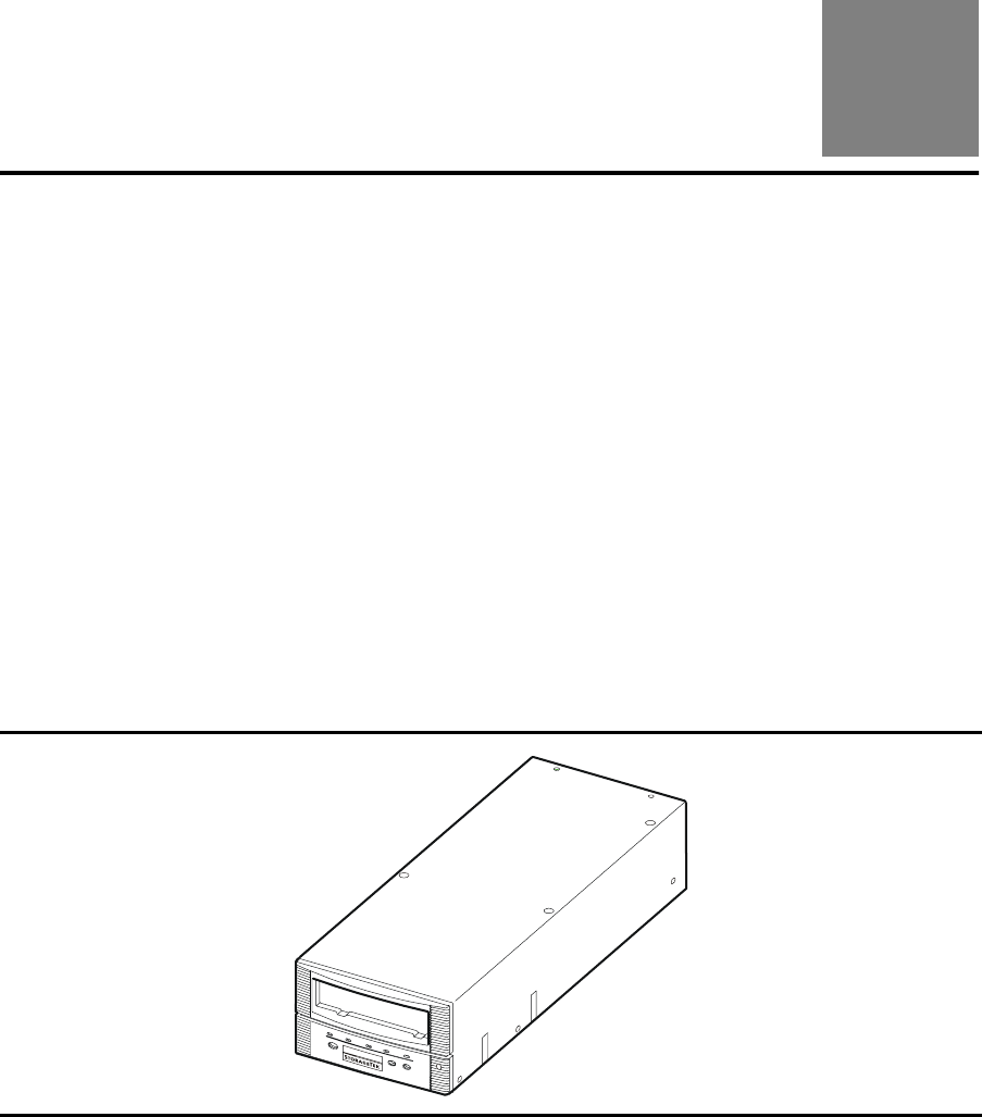
The 9840 Tape Drive is a small, modular, high performance tape drive. It is
82.6 mm (3.25 in.) high, 146 mm (5.75 in.) wide, and 381 mm (15 in.) deep.
Actual installed configuration requires additional space.
In the client-server environment, it is available in the following configurations:
•Desktop (manual load)
•Rack-mountable (single or dual manual load)
•Desktop Cartridge Scratch Loader (CSL)
•Rack-mountable CSL
•Automated library configuration
Figure 1-1. 9840 Tape Drive
C53970

Overview
1-2 Sixth Edition 95741
Host Interfaces
The 9840 Tape Drive interfaces with Fibre Channel and SCSI hosts. The drive
ships with a factory installed interface card that is not to be changed in the field
or at customer sites.
•The Fibre-Channel (FC) configuration of the 9840 Tape Drive has dual fiber-
optic ports to allow for point-to-point, arbitrated-loop (including redundant-
loop), and fabric topology. The FC interface for the 9840 Tape Drive uses
Fibre Channel protocol for SCSI (FCP-2).
•The SCSI interface card (ASIA—Application Specific Interface Adapter) has
only one port. The card can be programmed to different interface
specifications in the field from the drive operator panel.
Configurations
The drive is usually a component in a subsystem assembly that consists of the
drive, a power supply, and enclosures or trays, depending on the installation
environment. Refer to Table 1-1 for specific 9840 Tape Drive configurations and
interfaces.
Depending on the installation, the drive and power supply may be separated or
combined in an assembly. The FRUs (drive and power supply) may be attached
to a tray or installed within an enclosure.
Table 1-1. Configurations and Interfaces
Configuration Example Fibre
Channel SCSI
9840 Tape Drive Desktop Figure 1-2 on page 1-3 ✓✓
9840 Tape Drive Rack-
mountable Tray*
Figure 1-3 on page 1-3 ✓✓
9840 Tape Drive Desktop
CSL
Figure 1-5 on page 1-4 ✓✓
9840 Tape Drive Rack-
mountable CSLs*
Figure 1-6 on page 1-5 ✓✓
9738 Library Figure 1-8 on page 1-6 ✓✓
*Rack-mountable Drive and CSL trays may be intermixed within a single rack
cabinet.
95741 Sixth Edition 1-3
Desktop Unit
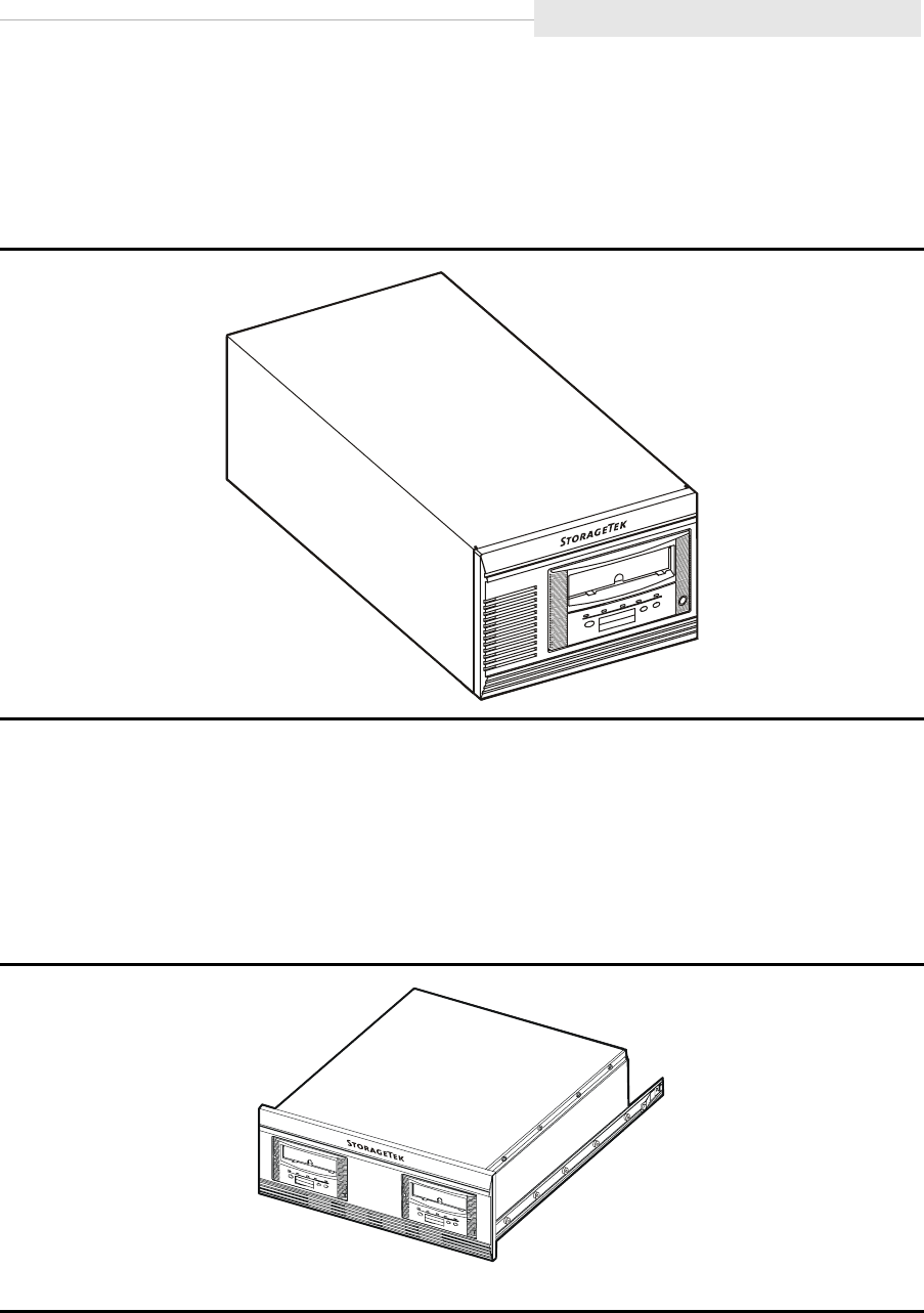
■Desktop Unit
The 9840 Tape Drive desktop unit (Figure 1-2) is a manual-load single drive,
with power supply, housed in a desktop cabinet.
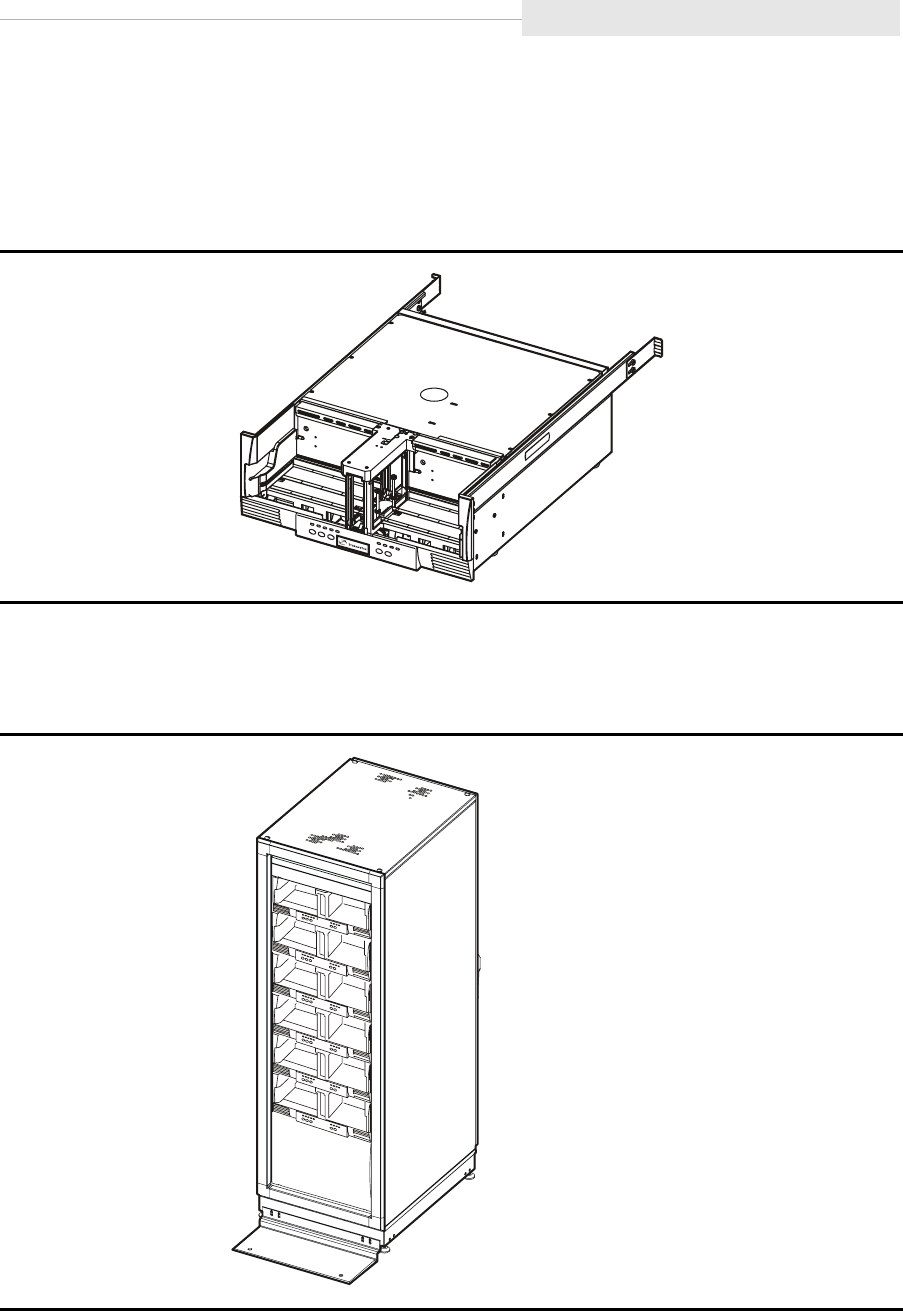
■Rack-mountable Drive Tray
The 9840 Tape Drive is also available in rack-mountable trays. Each tray
(Figure 1-3) can house a single manual-load drive or two manual-load drives,
plus a power supply for each drive. Any combination of trays can be used to fill
the rack cabinet slots. A different interface could be used for each tray.
Figure 1-2. 9840 Tape Drive Desktop Unit
Figure 1-3. 9840 Tape Drive Rack-mountable Tray
C53303
C53969
CSL Desktop Unit
1-4 Sixth Edition 95741
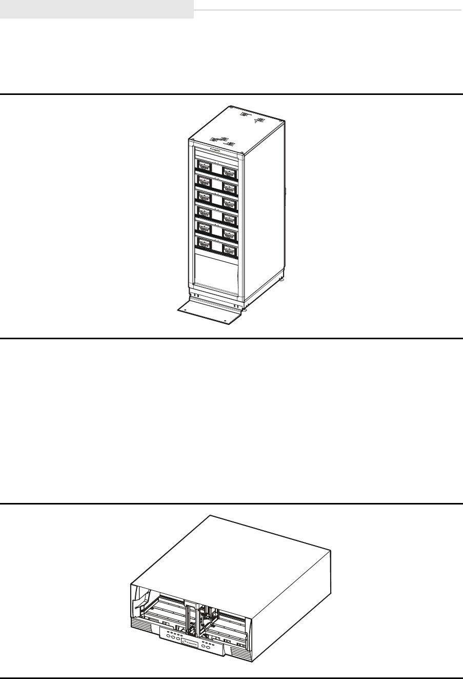
The StorageTek RACK001 cabinet (Figure 1-4) holds up to six trays. Any
combination of trays can be used to fill the rack cabinet slots.
■CSL Desktop Unit
The CSL desktop unit (Figure 1-5) consists of a 9840 Tape Drive, a power
supply, and a scratch loader mechanism. The CSL mechanism is an
electromechanical device that can load and unload up to seven cartridge tapes.
It also has a feed channel to mount a priority cartridge into the tape drive.
The desktop CSL is stackable up to a height of two units. Protective feet are
installed on the bottom of the unit to allow for stability.
Figure 1-4. StorageTek RACK001 Cabinet with Drive Trays
Figure 1-5. Desktop CSL Unit
C53305
C5397
1
95741 Sixth Edition 1-5
Rack-mountable CSL
■Rack-mountable CSL
The CSL is also available in a 19 inch tray (Figure 1-6) that can be mounted into
a rack cabinet.
Up to six CSL trays may be installed within the StorageTek RACK001
(Figure 1-7), or intermixed with drive trays.
Figure 1-6. CSL Rack-mountable Tray
Figure 1-7. StorageTek RACK001 with CSL Trays
C53656
C53659
9840 Tape Drive in 9738 Library
1-6 Sixth Edition 95741
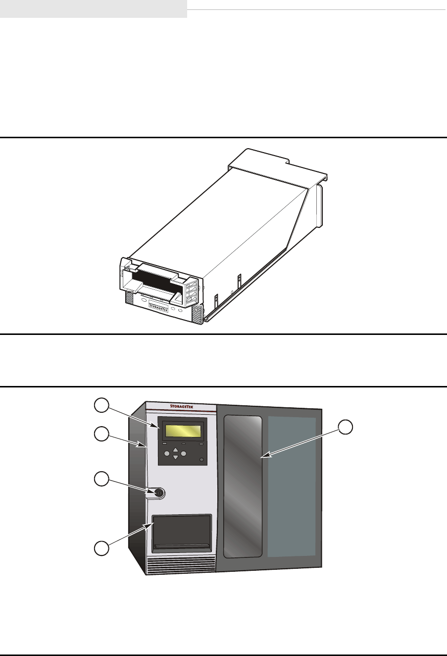
■9840 Tape Drive in 9738 Library
Figure 1-8 shows the 9840 Tape Drive used in a 9738 Library. It is mounted to a
tray for easy installation into the library. The 9840 Tape Drive when installed in
the 9738 Library uses a Fibre Channel or SCSI interface.
Figure 1-9 shows the front of the 9738 Library and its features.
Figure 1-8. 9840 Tape Drive Assembly for the 9738 Library
Figure 1-9. 9738 Library
1. Viewing Window
2. Cartridge Access Port (CAP)
3. Key Lock
4. Front Door
5. Operator Panel
C53304
C53505
1
2
3
4
5
95741 Sixth Edition 1-7
Operator Panels
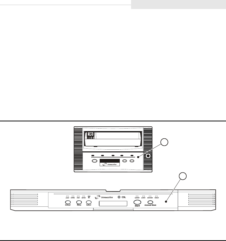
■Operator Panels
This section describes the operator panel switches, indicators, and the operator
panel display for the 9840 Tape Drive. There are two operator panels
(Figure 1-10) for the 9840 Tape Drive. They are:
•“Standard Operator Panel” on page 1-8
•“CSL Operator Panel” on page 1-13
Either operator panel enables you to view the configuration of the 9840 Tape
Drive, and notifies you when further support is required.
Note: The 9840 Tape Drive and use small push-button switches. The term
switch or switches is used to identify them throughout this manual.
Figure 1-10. 9840 Tape Drive Operator Panels
1. Standard Operator Panel
2. CSL Operator Panel
C53673
service
1
2
Operator Panels
1-8 Sixth Edition 95741
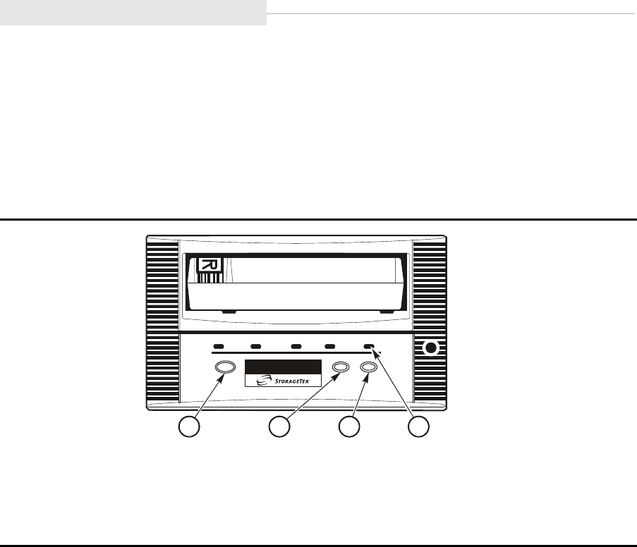
Standard Operator Panel
The standard operator panel (Figure 1-11) has a 10-digit display, four
pushbutton switches (switches), and four indicators.
Refer to Table 1-2 on page 1-9 for explanation of the standard operator panel
switches and Table 1-3 on page 1-11 for the use of the indicators.
Figure 1-11. Standard Operator Panel Switches
1. Unload
2. Menu
3. Select
4. IPL
C5367
5
1234

95741 Sixth Edition 1-9
Operator Panels
Standard Operator Panel Switches
Table 1-2 provides control descriptions of the 9840 Tape Drive operator panel
switches.
Table 1-2. Operator Panel Switches
Control Name Control Description
Unload This switch is used to rewind and unload the tape cartridge, ending
with the tape cartridge ejected and retrievable.
If Unload is pressed during a write operation, the drive attempts to write
the remaining data before it unloads. A display of UnWr xxxx
(meaning Unwritten Data, where xxxx is a fault symptom code) means
that the attempt failed and some data remains unwritten to tape.
Pressing Unload switch again will cause loss of this data. For the host to
save the unwritten data, the operator must issue the following
command sequence before pressing Unload again:
•In the SCSI environment: Recover Buffer Data
•In the Fibre Channel environment: Recover Buffer Data
Menu This switch is used to enter and exit the menu system and during
navigation of submenus. The menu system allows you to reconfigure
the drive or do special operations.
When in normal operation mode, pressing this switch will take you to
the Online/Offline top menu. To make changes in drive configurations
or do special operations, the drive must be offline, but if you only want
to view drive configurations, it may remain online. Use the Select
switch to change modes.
When in a main menu, with the drive offline, pressing Menu will step
you through the other main menus, bypassing the submenus (to enter
submenus, see Select Switch).
When in a submenu, pressing Menu will step you through the other
submenus or through different sections in a submenu.
The most important main menu selections are:
•Offline/online state
•Drive configuration choices
•Special drive operations
•Main exit
Detailed instructions are included in this manual where needed.

Operator Panels
1-10 Sixth Edition 95741
Select When in a main configuration menu, pressing this switch will select one
of the direct configuration/action choices in the main menu itself, or
select the underlying submenus, depending on the structure of the main
menu.
When in a Offline configuration submenu, pressing this switch will
select one of the direct configuration/action choices in the submenu.
When in Online, view only, configuration submenus, pressing Select is
same as pressing Menu.
Detailed instructions are included in this manual where needed.
IPL Pressing this indented switch causes the Initial Program Load (IPL) to
execute. This is identical to the IPL that takes place automatically after
power on sequencing is complete. Press IPL when necessary to reset
the drive. IPL Pend (IPL Pending) is displayed for one second when
this switch is pressed.
During IPL, the following are normally displayed in sequence:
•LOAD XXXX (XXXX = SCSI or FBCN)
•LOAD CC (load common controller code)
•LOAD SERVO (load servo code)
•Start Init (start initialization)
•(A corporate ID, indicating drive IPLed and is operational)
During IPL, the following errors can be displayed:
•Memory Err
•Boot Fail
Note: See Table 7-2 on page 7-3 for instructions on how to handle
error conditions or for an explanation of any additional display.
Following a successful IPL, display may alternate between an asterisk
(*) and xxxx:Dmpyy where: xxxx = fault symptom code (FSC), and
yy = number of uncollected dumps in the EEPROM.
Flashing stops and messages are removed when any tape is inserted or
any control is pressed.
Optionally, insert dump-formatted tape to collect dump data to tape.
Table 1-2. Operator Panel Switches (Continued)
Control Name Control Description
95741 Sixth Edition 1-11
Operator Panels
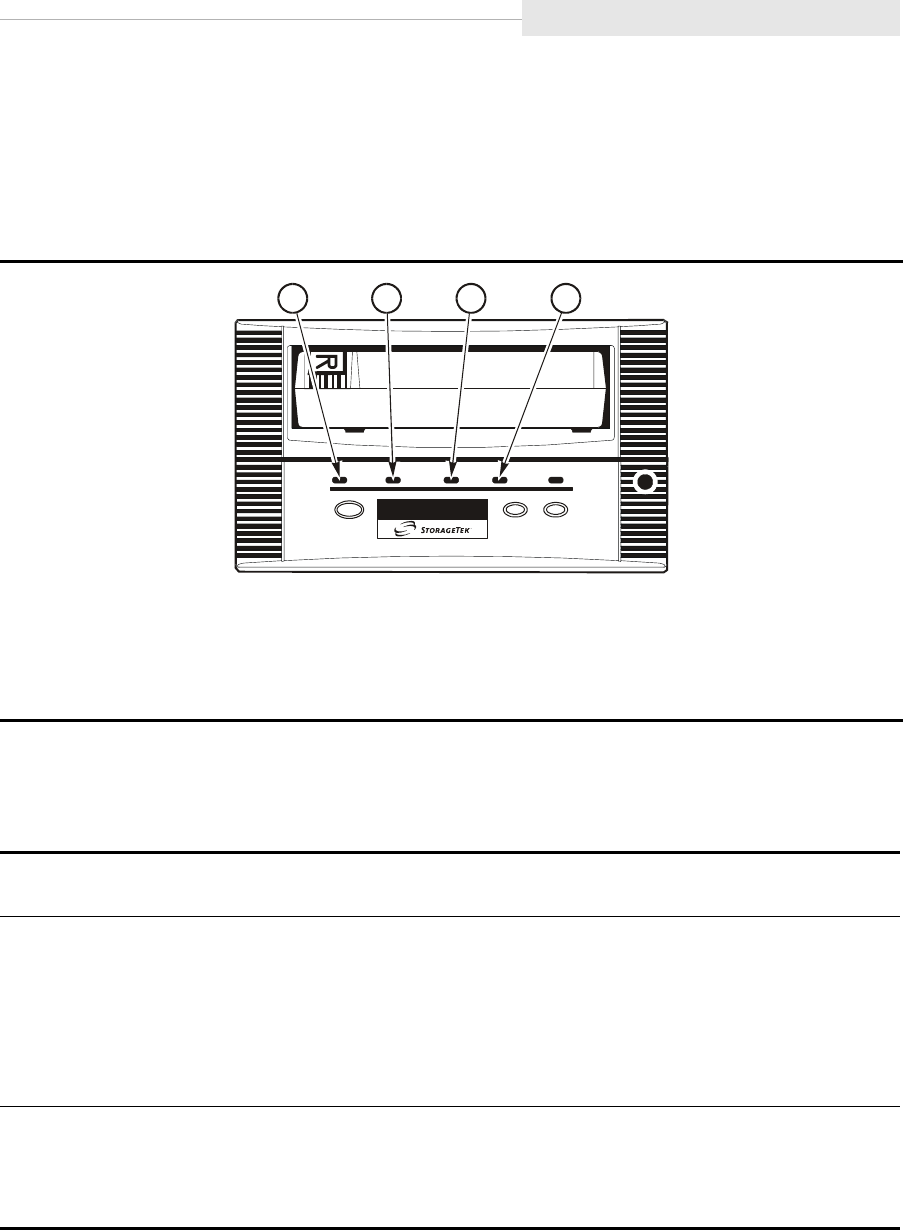
Standard Operator Panel Indicators
The operator panel indicators (Figure 1-12) can convey more information than
described below. For additional information, see Chapter 7, “Error and
Recovery.”
Table 1-3 provides a detailed explanation of the 9840 Tape Drive operator
panel indicators.
Figure 1-12. Standard Operator Panel Indicators
1. power
2. activity
3. clean
4. service
Table 1-3. Operator Panel Indicators
Indicator
Name Indication Explanation
power (green) Off:
Flashing:
Flashing doesn’t stop:
On (steady):
Power is off.
Unit is powering up, performing IPL, or
collecting dump.
IPL failed.
Power applied and IPL complete.
activity (green) Off:
Flashing:
On (steady):
Tape cartridge not loaded.
Tape cartridge loaded and tape is moving.
Tape cartridge loaded and tape is stopped.
C53674
4321

Operator Panels
1-12 Sixth Edition 95741
clean (amber) On (steady): Drive requires cleaning because of:
1. Distance, when a firmware defined length of
tape has passed over the R/W heads.
2. Error, after a read/write perm and at least half
the firmware defined length of tape has passed
over the R/W heads.
service (red) Off:
Flashing:
On (steady):
No error was detected.
An error/s detected and dump data is being
collected to the EEPROM.
If within one minute the drive detects the same
FSC, the message DumpAgain? is displayed: see
“DumpAgain? Indication” on page 7-12 for
instructions.
A hardware error was detected and drive is not
functional. A constant indicator cannot be
ignored by the operator. If a manually initiated
IPL doesn’t eliminate problem, the drive should
be replaced.
Table 1-3. Operator Panel Indicators (Continued)
Indicator
Name Indication Explanation
95741 Sixth Edition 1-13
Operator Panels
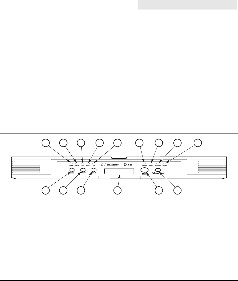
CSL Operator Panel
The CSL operator panel (Figure 1-13) allows a human interface to the
subsystem. When the 9840 Tape Drive is installed in a CSL, the 9840 Tape Drive
front operator panel switches and indicators are replicated on the left side of
the CSL front panel.
Note: See “Standard Operator Panel” on page 1-8 for tape drive specific switch
usage and indicator information.
The right side of the CSL front panel contains the switches and indicators
specifically for the CSL operation.
Note: See Chapter 5, “Cartridge Scratch Loader,” for CSL specific switch usage
and indicator information.
Figure 1-13. CSL Operator Panel
1. power indicator
2. activity indicator
3. clean indicator
4. service indicator
5. IPL switch
6. operator indicator
7. system indicator
8. automatic indicator
9. manual indicator
10. Unload switch
11. Menu switch
12. Select switch
13. Operator display
14. Start switch
15. Autoload Mode switch
Note: The IPL switch (5) initiates IPL for the drive only. The Power switch on the back of
the CSL initiates IPL for the CSL and the drive.
C53660
123 45 6
7
8
9
10 11 12 13 14 15

Operator Panels
1-14 Sixth Edition 95741
Display
The operator panel has an alphanumeric display that indicates:
•Drive status
•Menu selections and configuration choices
•Error messages and fault symptom codes
•Host-generated messages
•Tape bar, if activated
The display is formed by a horizontal array of 10 segments. Each segment is
formed by an array of 35 dots—five wide and seven high. When the tape bar is
not activated, the lighted segments and dots form text messages. The text
messages may display steadily, flashing, or alternating with other messages.
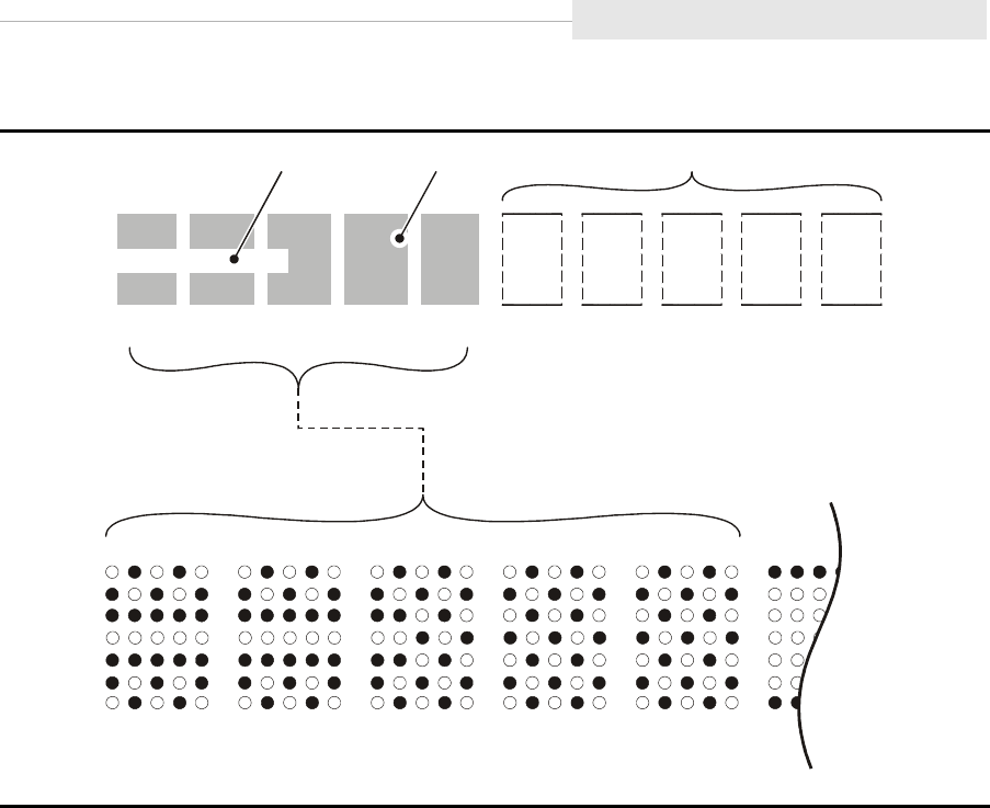
Tape Bar
The tape bar uses the operator panel display to show the amount of tape that
has been written and read (Figure 1-14 on page 1-15). The tape bar is a
configuration option that must be activated by authorized service personnel.
Once activated, it appears on the operator panel display when the drive is
reading or writing.
When the tape bar is activated, the segments and dots simultaneously show the
percentage of the total tape length that has been written and read. Each dot
represents 2% of the tape length; each segment represents 10%.
Note: The tape bar gets its information from the media information region
(MIR) on the tape. The MIR is written to the tape when the tape is
unloaded. If the MIR is bad, the tape bar does not display. To rewrite the
MIR, see (TBD).
Write Bar
As data is written to tape, the lighted dots forming the write bar appear at the
left side of the display and advance to the right. The write bar uses the full
height of the display. As the dots fill the display, note that only every other dot
is lighted. The point where the write bar ends is the percentage of tape written.
Read Bar
As data is read from the tape, the read bar appears in the center of the write bar
as a single row of unlighted dots. This row is bordered above and below by
single rows of lighted dots. The read bar also begins at the left side of the
display and advances to the right. The point where the read bar ends is the
percentage of tape that has been read.
95741 Sixth Edition 1-15
Operator Panels
Figure 1-14. Tape Write/Read Bar Chart
C53272
10% 20% 30% 50% 60% 70%
80%
90%
100%
40%
10% 20% 30% 40% 50%
READ BAR
(2
4
%)
WRITE BAR
(
5
0%)
UNWRITTEN AREA

Cartridges
1-16 Sixth Edition 95741
■Cartridges
Currently, there are two types of 9840 tape cartridges (Figure 1-15 on
page 1-17). Customers may purchase the standard and the VolSafe cartridge.
•The standard cartridge uses white labels and can be write protected. If not
write protected, data can be written over. Refer to Table 1-4.
•The VolSafe cartridge uses yellow labels and cannot be written over. Data
can only be appended to the information on the cartridge. Refer to
Table 1-4.
The cartridges have one supply and one take-up reel. The design allows for
mid-point loading and provides an average access-to-data time of 11 seconds.
The dual-hub architecture yields a load/initialize time of 4 seconds.
The 9840 Tape Drive cartridges have the same dimensions as the 18- and 36-
track tape drive cartridges. This allows mixing of cartridges within existing
libraries.
Note: See Cartridge Specifications in Appendix A, “Specifications,” for more
specific information.
Do not use a VolSafe tape to make a dump, code, data tape, or to build
an MIR. A “Write Prot” message displays if a VolSafe tape is used.
Table 1-4 shows the similarities of the standard and VolSafe cartridges.
Table 1-4. Standard and VolSafe Cartridges
Feature Standard VolSafe
1. Manufacturer Label Area White Yellow
2. Customer Label Area White White
3. Access Door Same Same
4. Write Protect Switch White Yellow
5. Finger Grips Same Same
6. Volser Label Area Same Same
7. Media ID
(human or barcode identifiable)
White Yellow
8. Media ID
(machine identifiable)
Flush dimples
(all four)
First dimple
recessed
9. Manufacturer Part ID White White
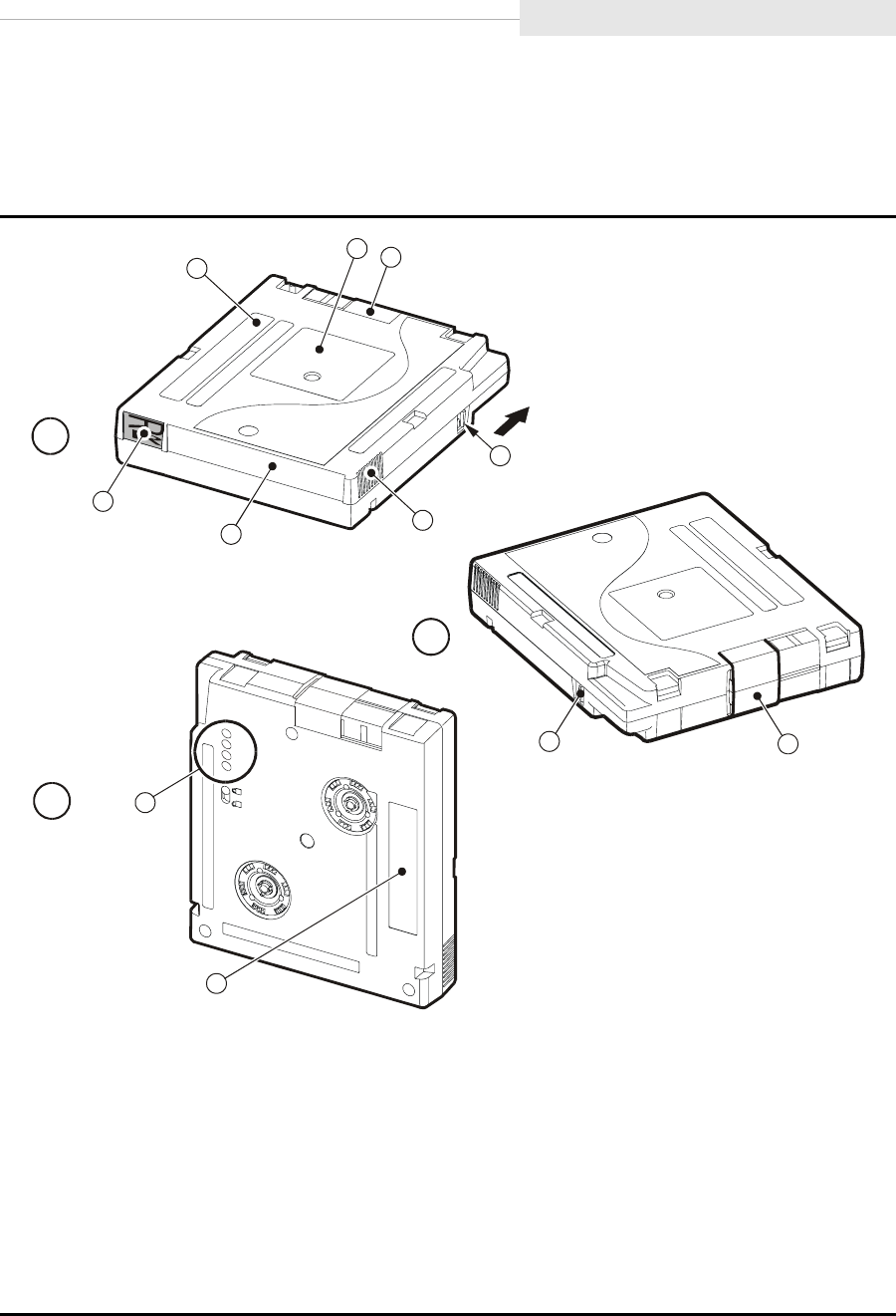
95741 Sixth Edition 1-17
Cartridges
9840 Tape Cartridge
Figure 1-15 provides specific features of the 9840 tape cartridge.
Figure 1-15. 9840 Tape Cartridge
Components of the 9840 Tape Cartridge
A. Rear view
B. Front view
C. Bottom view
1. Manufacturer label (Std - White, VolSafe - Yellow)
2. Customer label
3. Access door
4. Write-protect switch (Std - White, VolSafe - Yellow)
5. Finger grips
6. VOLSER label
7. Media ID (Std - White, VolSafe - Yellow)
(human or barcode readable)
8. Media ID (machine readable)
(First dimple recessed on VolSafe)
9. Manufacturer Part ID
C53217
13
5
6
A
7
2
4
B
4
3
8
9
C

Cartridges
1-18 Sixth Edition 95741
This page intentionally left blank.

95741 Sixth Edition 2-1
2
Safety and Handling
This chapter covers topics that are essential to all installation and service
activity:
•“Safety Precautions”
•“Electrostatic Discharge (ESD) Damage Prevention” on page 2-3
•“Fiber Optic Safety” on page 2-5
Read the following pages and become familiar with these guidelines before
beginning any service activity.
■Safety Precautions
CAUTION:
Potential injury: On-the-job safety is very important; therefore, observe
the following safety precautions while you are engaging in any
maintenance activity. Failing to follow these precautions could result in
serious injury.
Remove all conductive jewelry, such as watches and rings, before you
service powered-on equipment.
•Avoid electrical shock. Be careful when you work near power
connectors and supplies.
•Power off the equipment that is being serviced before you remove a
field replaceable unit (FRU) or other component. Remember that
dangerous voltages could still be present in some areas even though
power is off.
•Ground all test equipment and power tools.
•Lift objects properly; read the information in “Lifting Techniques” (see
below).
•Do not remove, cut, or relocate any floor tiles indiscriminately. Before
you manipulate floor tiles, be sure that you understand the customer's
environment and receive the customer's approval. Remember, each
situation is different.
•Enforce good housekeeping practices in the equipment area to help
prevent accidents or fire.

Safety Precautions
2-2 Sixth Edition 95741
Note: Important things to investigate and to be aware of include the use of
Halon® gas, under-the-floor smoke detectors, and cables to other
equipment nearby.
Lifting Techniques
Lifting, regardless of how much or how little, can create serious back stress. If
you follow these guidelines, you can reduce the risk of back injury:
•Do not twist your body to pick something up or put it down. Twisting
puts extreme pressure on your back, especially when you lift or carry
objects. Instead of twisting, make the task two separate moves; first, lift,
and then use your feet to turn your body.
•Plan the lift: first examine the object and then determine how it will be
lifted and where it will be placed.
•Choose the appropriate lifting technique. Examine the weight, size,
location, frequency, and direction of the lift. Plan to avoid awkward
postures, and determine if material-handling aids are needed.
•Place your feet shoulder-width apart, and place one foot a little behind
the other. Keep your back straight because even light loads can
significantly increase pressure on the spine when you lean forward.
•Whenever you can, grip the load with your whole hand, and use two
hands.
•Carry objects at elbow height and close to your body. The farther away
you hold an object, the more force it puts on your lower back.
•Lift with your legs instead of your back. Leg muscles are some of the
strongest in your body. When you squat and lift with your legs, you can
lift more weight safely.
•Alternate lifting tasks with tasks that are less stressful to the same
muscles. This technique ensures that your muscles have some recovery
time.
Shoulder, Elbow, Wrist, and Hand Safety
Follow these guidelines to minimize the possibility of injury to your shoulders,
elbows, wrists, and hands.
•Work within your safety zone–the area between shoulder level and
knuckle level of your lowered hands. You face less chance of injury
when you work or lift in this area.
•Keep your elbows bent to keep loads close to your body and to
decrease the amount of force necessary to do the job. If you use this
posture, you will put less weight and pressure on your shoulder.

95741 Sixth Edition 2-3
Electrostatic Discharge (ESD) Damage
•Be sure to keep your wrists straight. Avoid bending, extending, or
twisting your wrists for long periods of time.
•Do not use a pinch grip to lift large or heavy loads because the way you
lift also can affect the tendons in your hand. When you grasp an object
between your thumb and fingers, you put a lot of tension on hand and
wrist tendons. Use both hands–use one for a while, and then use the
other–to give them rest.
■Electrostatic Discharge (ESD) Damage Prevention
Anyone who handles ESD-sensitive components must be aware of the damage
that ESD can cause to electronic components and must take the proper
precautions to prevent it. Also, anyone who performs maintenance on
StorageTek equipment must complete an ESD-basics course.
CAUTION:
Potential damage to equipment: Handle ESD-sensitive components only
under ESD-protected conditions. To meet this requirement, always use a
grounding kit and always follow these ESD precautions and procedures
when you are servicing equipment or handling ESD-sensitive
components.
ESD Precautions
Always take the following general precautions when you work with ESD-
sensitive components:
•Wear ESD protection whenever you install, remove, maintain, or repair
equipment.
•Keep ESD-sensitive printed-circuit components in their ESD-protective
packages until you have taken all ESD-preventive steps and you are ready
to install the component.
•Do not allow anyone to touch or handle an unprotected ESD-sensitive
component unless that person has taken all ESD precautions.
•Reinstall all equipment covers and close all equipment doors after you have
completed the work.
•If the grounding-kit work surface has been exposed to temperatures above
66ºC (150ºF) or below 4.5ºC (40ºF), acclimate the work surface to room
temperature before you unroll it.
•Immediately place any component that you have removed into an ESD-
protective package.
•Keep the grounding-kit work surface clean.

Electrostatic Discharge (ESD) Damage
2-4 Sixth Edition 95741
•To clean the work surface, use a mild detergent and water, and make sure
that the surface is completely dry before you use it.
•Periodically check the electrical resistance of the ground cord and the wrist-
strap coil cord.
Note: The ground cord should measure less than 1.2 MΩ, and the coil cord
should measure between 0.8 and 1.2 MΩ. Repair or replace the
cords if they no longer meet these requirements.
ESD-Protection Procedure
Remember that each customer environment is different. Address all the
customer’s concerns before you work on any equipment.
Prepare the Work Area
1. Before you service the equipment, unfold the grounding-kit work surface
completely and place it on a convenient surface.
2. Attach one end of the ground cord to the work surface; secure the snap
fastener.
Note: You will attach the free end in a later step.
3. Slip on an ESD wrist strap. Make sure that the strap is comfortable and
makes contact with the entire circumference of your wrist.
4. Snap one end of the coil cord to the wrist band.
Access the Equipment
5. Carefully open the doors to the equipment or remove the covers from the
equipment. Do not touch any internal components.
CAUTION:
Be sure that you are properly grounded before you touch any internal
components.
6. Attach the free end of the coil cord to the most appropriate place:
a. If you are working on components from a small piece of equipment,
attach the free end of the coil cord to the grounding-kit work surface. In
addition, be sure that you touch an unpainted metal surface on the
equipment before you touch an internal component.
b. If you are working on components from a large piece of equipment,
attach the free end of the coil cord to a grounding jack or to an
unpainted metal surface inside the equipment.

95741 Sixth Edition 2-5
Fiber Optic Safety
Replace Components
7. Remove the defective component and place it on the work surface.
8. Remove the replacement component from its ESD-protective package, and
install the component in the equipment.
9. Place the defective component in the ESD-protective package.
Clean Up
10. Disconnect the ground cords from the equipment.
11. Reinstall all equipment covers and close all equipment doors.
12. Disconnect the coil cord from your wrist, and, if necessary, disconnect the
ground cord from the work surface.
13. Properly store the work surface and the other Field Service Grounding Kit
items.
■Fiber Optic Safety
StorageTek products use both light emitting diodes (LEDs) and laser multi-mode
transmitter-receiver (transceiver) modules. LED transceivers use low power and
are not as dangerous as laser transceivers.
WARNING:
Eye hazard. Never look directly into a fiber-optic cable, a fiber-optic
connector, or a laser transmitter-receiver module. Hazardous conditions
might exist from laser power levels that are capable of causing injury to
the eye.
Be especially careful when using optical instruments with this
equipment. Such instruments might increase the likelihood of eye injury.
The laser transceivers in fiber-optic equipment can pose dangers to personal
safety. Ensure that anyone who works with this StorageTek equipment
understands these dangers and follows safety procedures. Ensure that the
optical ports of every laser transceiver module are terminated with an optical
connector, a dust plug, or a cover.
Each fiber-optic interface in this StorageTek Fibre Channel equipment contains
a laser transceiver that is a Class 1 Laser Product. Each laser transceiver has an
output of less than 70 µW and a wavelength of 850 nm. StorageTek’s Class 1
Laser Products comply with EN60825-1(+A-11) and with sections 21 CFR
1040.10 and 1040.11 of the Food and Drug Administration (FDA) regulations.

Laser Product Label
2-6 Sixth Edition 95741
The following translations are provided for Finland and Sweden who wish to
identify laser safety and classification:
CLASS 1 LASER
LUOKAN 1 LASERLAITE
KLASSE 1 LASER APPARAT
■Laser Product Label
In accordance with safety regulations, a label on each StorageTek Fibre Channel
product identifies the laser class of the product and the place and date of the
manufacturer. The label appears on top of a Fibre Channel tape drive and near
the Fibre Channel connectors on a Fibre Channel tape library. A copy of the
label is shown here:
■Fiber-Optic Cable Handling
Observe these precautions when you handle fiber-optic cables:
•Do not coil the cable to less than 96 mm (3.75 in.) in diameter.
•Do not bend the cable to less than 12 mm (0.5 in.) in radius. StorageTek
recommends that a cable’s bend radius be no less than 20 times the
diameter of the cable.
•Do not pull on the cables; carefully place them into position.
•Do not grasp the cables with pliers, grippers, or side cutters; do not attach
pulling devices to the cables or connectors.
•Keep cables away from sharp edges or sharp protrusions that could cut or
wear through the cable; make sure that cutouts in the equipment have
protective edging.
•Protect the cable from extreme temperature conditions.
WARNING:
Eye hazard. Never look directly into a fiber-optic cable, a fiber-optic
connector, or a laser transceiver module. Hazardous conditions might
exist from laser power levels that are capable of causing injury to the
eye.
Be especially careful when using optical instruments with this
equipment. Such instruments might increase the likelihood of eye injury.
•Install the connector’s protective cover whenever the connector is not
connected.
CLASS 1 LASER PRODUCT
LASER KLASSE 1
APPAREIL A LASER DE CLASSE 1
COMPLIES WITH 21 CFR 1040.10 AND 1040.11

95741 Sixth Edition 2-7
Fiber-Optic Cable Installation
■Fiber-Optic Cable Installation
Follow these guidelines when you install fiber-optic cables:
1. Cable routing:
•Raised floor: You may install fiber-optic cables under a raised floor.
Route them away from any obstruction, such as existing cables or other
equipment.
•Cable tray or raceway: Place the cables in position; do not pull them
through the cable tray. Route the cables away from sharp corners,
ceiling hangers, pipes, and construction activity.
•Vertical rise length: Leave the cables on the shipping spool, and lower
them from above; do not pull the cables up from below. Use proper
cable ties to secure the cable.
•General: Do not install fiber-optic cables on top of smoke detectors.
2. Cable management:
•Leave at least 4.6 m (15 ft) of cable at each end for future growth.
•Use strain reliefs to prevent the weight of the cable from damaging the
connector.
•Review all information in this manual and in any related manuals about
safely handling fiber-optic cables.
WARNING:
Eye hazard. Never look directly into a fiber-optic cable, a fiber-optic
connector, or a laser transceiver module. Hazardous conditions might
exist from laser power levels that are capable of causing injury to the
eye.
Be especially careful when using optical instruments with this
equipment. Such instruments might increase the likelihood of eye injury.
3. Connector protection:
•Insert connectors carefully to prevent damage to the connector or fiber.
•Leave the connector’s protective cover in place until you are ready to
make connections.
•Replace the connector’s protective cover when the connector is
disconnected.
•Clean the connector before making a connection. Make sure that there
are no obstructions and that keyways are aligned.

Fiber-Optic Cable Installation
2-8 Sixth Edition 95741
This page intentionally left blank.

95741 Sixth Edition 3-1
3
Installation
The 9840 Tape Drive can be installed as a desktop, rack-mountable drive,
desktop Cartridge Scratch Loader (CSL), rack-mountable CSL, or within a 9738
library.
A desktop unit or desktop CSL contains a drive with either a Fibre Channel (FC)
or Small Computer System Interface (SCSI) interface.
The StorageTek RACK001 can hold up to six CSL trays, drive trays, or any
combination.
•The rack-mountable drive tray is available with FC or SCSI interface
connections. A single tray contains one or two drives (both drives must
have the same type of interface).
•The CSL tray is available with a FC or SCSI interface.
The 9738 Library may contain up to three drives with a FC or SCSI interface.
This chapter contains installation instructions for each configuration. It also
provides cabling instructions to the host system(s).
Note: When installing the 9840 Tape Drive in a 9738 library, always use this
chapter together with the 9738 Library Product Manual.

Verify all Equipment has Arrived
3-2 Sixth Edition 95741
■Verify all Equipment has Arrived
Check the equipment against the shipping invoice to make sure that all the
ordered equipment has arrived. You can only check some items, such as cables,
after the equipment is unpacked.
■Unpacking the Shipment
Follow these steps to unload the equipment (drives, CSL or drive trays, or a
rack):
WARNING:
Personal injury or equipment damage. Be aware of floor openings,
cables, and other obstructions that might injure you or damage the
equipment while you are moving and positioning the equipment.
1. Move the equipment as close as possible to the installation area. The rack
has casters and can be rolled into the final position.
2. Open the shipping carton and remove the contents.
Note: Make arrangements with the customer to dispose of the shipping
cartons and packaging material.
3. Position the unpacked equipment near the final location according to the
customer’s floor plan, but leave enough space to enable you to connect and
route the cables.
Note: Service clearances for the rack configuration are shown in Figure 3-1
on page 3-3.
■Inspecting the Equipment
1. Remove all accompanying documentation (such as the 9840 Tape Drive
Product Manual) and component packages, then place them aside.
2. Make sure the serial numbers correspond with the shipping invoice.
3. Make sure the required cables are available:
•Table 3-1 on page 3-4 lists the FC cables that connect the 9840 Tape
Drive to Fibre Channel hubs or host bus adapters (HBAs). Figure 3-2 on
page 3-4 shows the connector.
•Table 3-2 on page 3-5 lists the SCSI cables that connect the 9840 Tape
Drive to HBAs. Figure 3-3 on page 3-5 shows the cable connectors.
4. Report any missing or incorrect contents to the Louisville plant.
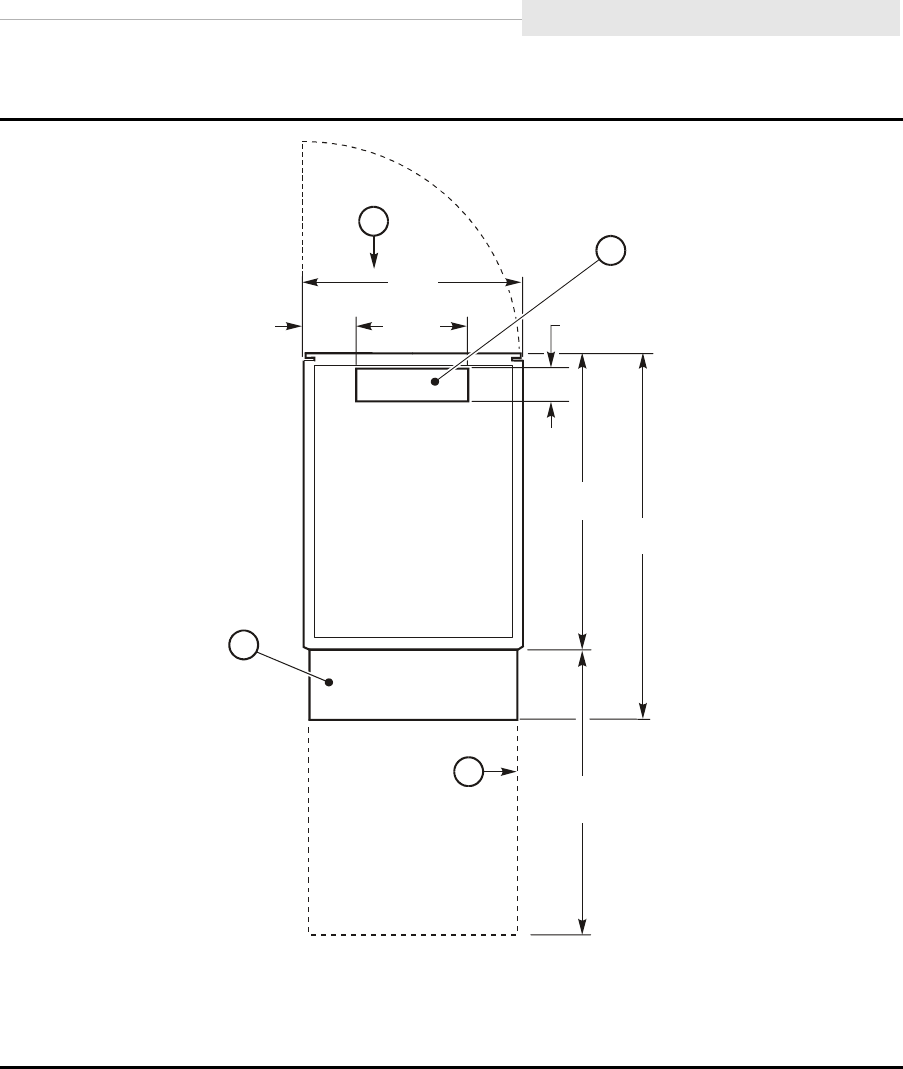
95741 Sixth Edition 3-3
Inspecting the Equipment
Figure 3-1. RACK001 Floorspace (Top View)
1. Rear door clearance
2. Cable cutout in floor of rack
3. Service clearance
4. Stabilizer
C53684
153
(6.02) 300
(11.8)
606
(23.9)
60.5
(2.38)
798
(31.4)
100
(3.94)
1.025 m
(40.4)
762
(30)
1
2
3
4
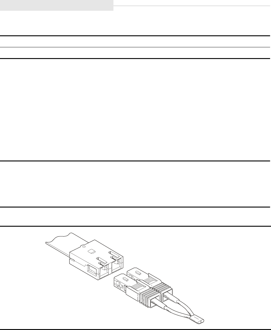
Inspecting the Equipment
3-4 Sixth Edition 95741
Note: The cable connector is keyed so the cable can only be inserted one way.
The cable acts somewhat like a null modem cable in that the transmit from one
end of the cable connects to the receive at the other end of the cable. The cable
connectors are typically labeled A and B. In addition, one strand of the cable is
labeled (with the vendor name and other information) while the other strand is
unlabeled.
Table 3-1. Fibre Channel Cable (SC to SC Connectors) Part Numbers
Length Part Number
Meters Feet Plenum1Riser2
2 6.6 10800122 10800132
5 16.4 10800123 10800133
10 32.8 10800124 10800134
20 65.6 10800125 10800135
30 98.4 10800126 10800136
50 164 10800127 10800137
100 328.1 10800128 10800138
250 820.2 10800129 10800139
500 1640.4 10800130 10800140
Notes:
1. Plenum cables are designed for installation in air ducts. Plenum materials are
manufactured to meet UL standards for flammability (produce little smoke).
2. Riser cables can be used in computer rooms. Riser cable materials are not classified
according to flammability or toxic gas emissions.
Figure 3-2. Fibre Channel Cable Connector
C5368
5
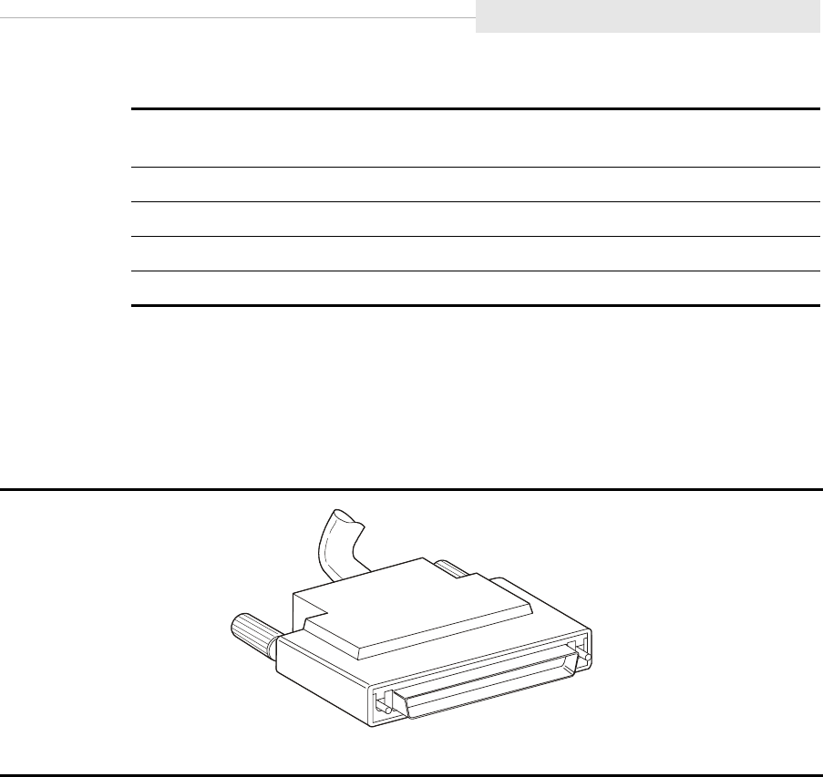
95741 Sixth Edition 3-5
Hubs
A 9840 Tape Drive can be connected to an AS/400 through a 6501, 6534, or
2729 IOP using a 68-pin SCSI cable (listed in the preceding table).
Note: The 6501 IOP also requires an interposer (order from IBM P/N
05H3834).
■Hubs
Because of the fast growth and the increased demand for FC attachments, hubs
can provide cascading (multiple) loops within a FC network. StorageTek tape
drives are designed to use hubs to provide for an arbitrated loop which
provides the following capabilities:
•Centralizes the attachment of the tape drives within the arbitrated loop
•Establishes connections with fiber-optic cables
•Provides translation of physical media (such as copper to optical fiber)
•Provides an external power supply for the port bypass
•Provides port bypass functionality for port failures
•Allows cascading to increase tape drive and initiator attachment
Table 3-2. SCSI Cable Part Numbers
Standard Rated
Cable (CL2)
Plenum Rated
Cable (CL2P) Length (meters) Length (feet)
10083309 1008313 3 10
10083310 1008314 4 20
10083311 1008315 15 49
10083312 1008316 20 65
Figure 3-3. SCSI Cable Connectors
C53686

Begin the Hardware Installation
3-6 Sixth Edition 95741
•Supports the ability to power-on and -off, install, or deinstall tape drives
•Provides a central point of port management and monitoring of the tape
drives
•Extends the distances between tape drives and initiators
Considerations
Jitter is a consideration when selecting, installing, and configuring hubs within a
Fibre Channel network. Jitter is the deviation of timing of an exchange.
The accumulation of jitter occurs and continues to grow within a chain of
repeaters. As a signal is input to a repeater, jitter is not removed from the clock
and is transferred to the data at the output. At some level within the network,
jitter could exceed the allowable limit causing excessive errors. Assuring that
there are NL_Ports within the loop to reclock the signal, jitter will be minimized.
Loop Port State Machines (LPSM) are required to control the operation of the
loop and ensure Loop Initialization Protocol (LIP) is executed whenever a reset
or power-on occurs.
Cascading Fibre Channel Hubs
Cascading of hubs allows an increase of tape drive and initiator attachments
within the arbitrated loop. There is no limit to the number of cascading hubs
within a network as long as basic guidelines are followed (refer to the hub
manufacturer’s requirements).
Figure 3-4 on page 3-7 shows a network incorporating cascading hubs. Notice
that port 1 and port 4 are used for connecting hubs together.
■Begin the Hardware Installation Process
Use the list below to determine where to begin:
•“9738 Library Attachment” on page 3-8
•“Desktop Units” on page 3-19
•“Rack” on page 3-26
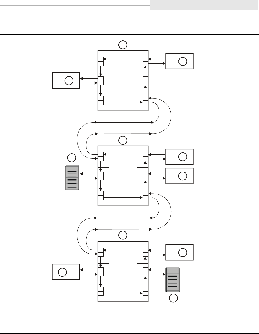
95741 Sixth Edition 3-7
Begin the Hardware Installation
Figure 3-4. Cascading Hubs
1. 9840 Tape Drive
2. Hub
3. Server
C5368
7
1
1
1
2
2
2
3
3
3
4
4
4
5
5
5
6
6
6
1
2
1
3
2
1
1
1
2
1
3
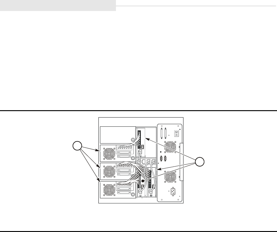
9738 Library Attachment
3-8 Sixth Edition 95741
■9738 Library Attachment
Figure 3-5 shows the rear of the 9738 Library (some sheet metal has been
removed for clarity). Follow the procedures in this section to:
•Insert the 9840 Tape Drive/tray assembly and power supply into the 9738
library
•Cable the drive to the library and the host system
This section contains the following 9738 Library and 9840 Tape Drive
procedures:
•“Prepare and Install the Drive” on page 3-9
•“Install Power Supplies” on page 3-11
•“Connect Drive and Library Cables” on page 3-12
•“Install Host Interface Cables” on page 3-13
•“Apply Power to Library Drive” on page 3-18
•“Install a Cleaning Cartridge” on page 3-18
Figure 3-5. 9738 Library Attachment
1. Drives
2. Power Supplies
C53983
1
2
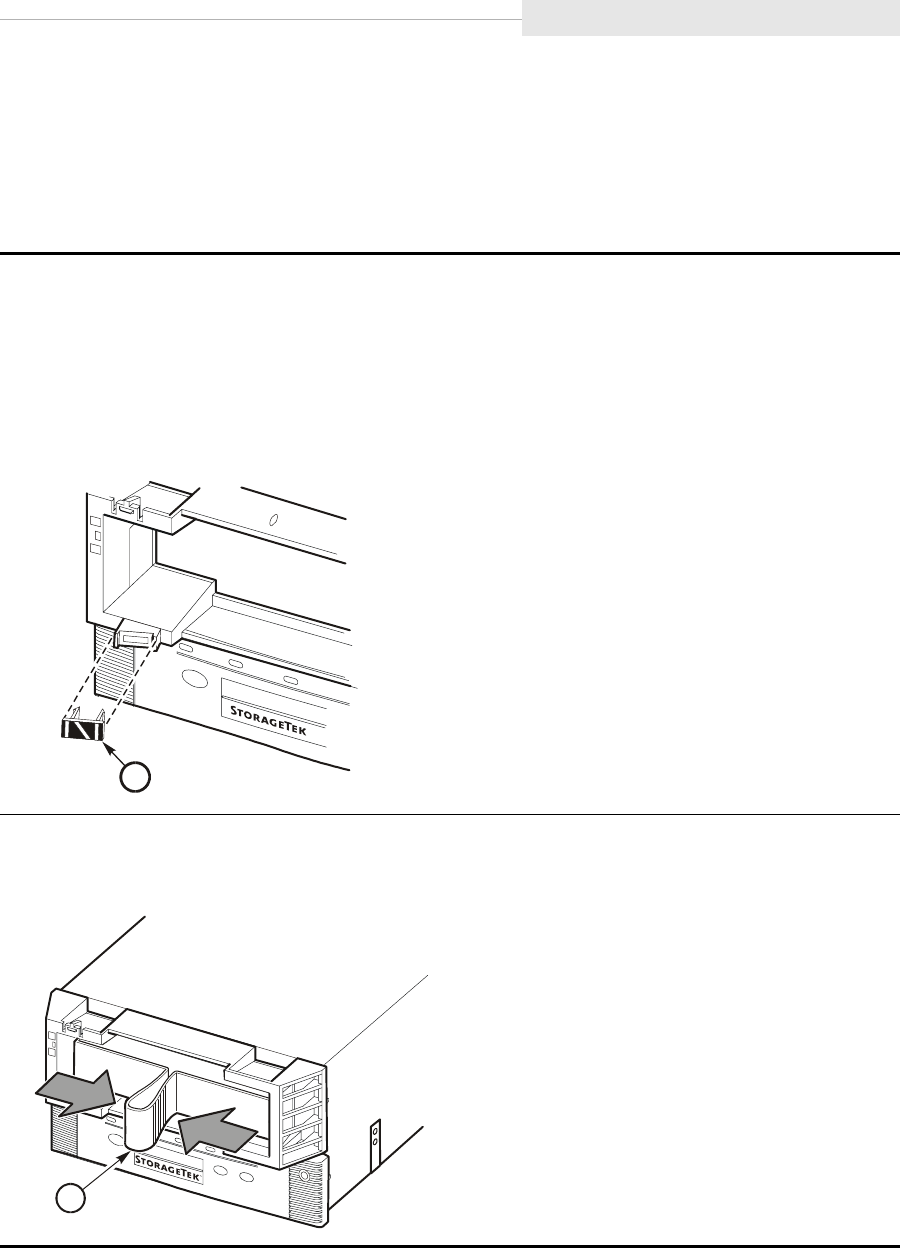
95741 Sixth Edition 3-9
9738 Library Attachment
Prepare and Install the Drive
Use the instructions below to install the drive:
Note: It is assumed that the drive has been unpackaged per the instructions in
“Unpacking the Shipment” on page 3-2.
1. Inspect the target for damage (such as white scratched off the target).
a. If the target is damaged, obtain a replacement target (PN 300048901).
b. Remove the damaged target and snap the new one into the opening shown in the
figure below.
Note: The drive ships with the target installed in the bezel.
1. Library horizontal target
2. Remove the shipping insert from the drive bezel by squeezing both sides of the handle
together and pulling it out from the drive (see figure).
1. Shipping insert
C5334
7
1
C53218
1
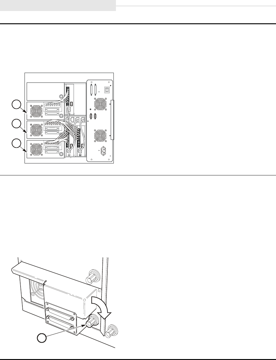
9738 Library Attachment
3-10 Sixth Edition 95741
3. Set the drive tray onto the bottom edge of the drive slot.
Note: The first drive is placed in the bottom slot position. See figure.
4. Push the tray fully into the drive slot.
1. Drive 0
2. Drive 1
3. Drive 2
CAUTION:
If the tray is not fully tightened, the library may not be able to calibrate the drive(s).
5. Turn the tray latch to the right (clockwise) until tight (see figure).
Note: You should test the drive tray for play by grasping it and pulling back. If you feel
any looseness, retighten the tray latch.
6. Repeat Steps 1 through 5 for all remaining drives.
1. Tray latch
C5324
8
3
1
2
E53369
1
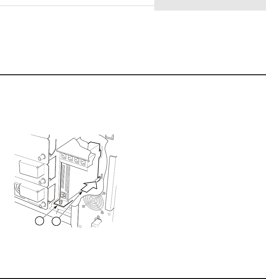
95741 Sixth Edition 3-11
9738 Library Attachment
Install Power Supplies
Install power supplies in the 9738 between the drive slots and the electronics
module. Use the instructions below to attach a power supply to the 9738:
Note: Ensure the power supply switch is off.
1. Open the rear cover of the library.
2. Slide the power supply into the library.
a. Make sure to seat the metal tab into the slot at the rear of the chamber (see figure).
b. Place the power supply for Drive 0 in the lower left (see figure).
1. Metal tab
2. Mounting screw
3. Tighten the mounting screw.
4. Repeat Steps 2 and 3 for all remaining drive power supplies.
Note: Place the power supply for Drive 1 in the lower right, and the power supply for
Drive 2 in the upper left.
E53249
21
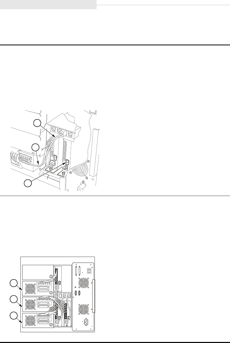
9738 Library Attachment
3-12 Sixth Edition 95741
Connect Drive and Library Cables
Follow these instructions to connect the drive to the power supply and library:
1. Locate the plastic bag containing the power cord.
2. Make sure the power switch on the power supply is in the OFF position.
3. Connect P2 of the drive power cable to the top jack (J2) on the power supply (see
figure), and the P53 connector to the top jack on the drive.
4. Connect the female end of the power cord to the power supply receptacle (J1), and the
male end of the cord to a power outlet in the library (see figure).
1. Power cord
2. Power supply cable
3. Power switch
5. Repeat Steps 1 through 4 for remaining drive positions.
Note: Use the figure below as a guide for routing the drive power cable from a power
supply to the proper drive.
•The lower-left power supply connects to Drive 0.
•The lower-right power supply connects to Drive 1.
•The upper-left power supply connects to Drive 2.
1. Drive 0
2. Drive 1
3. Drive 2
E53250
1
2
3
C5324
8
3
1
2
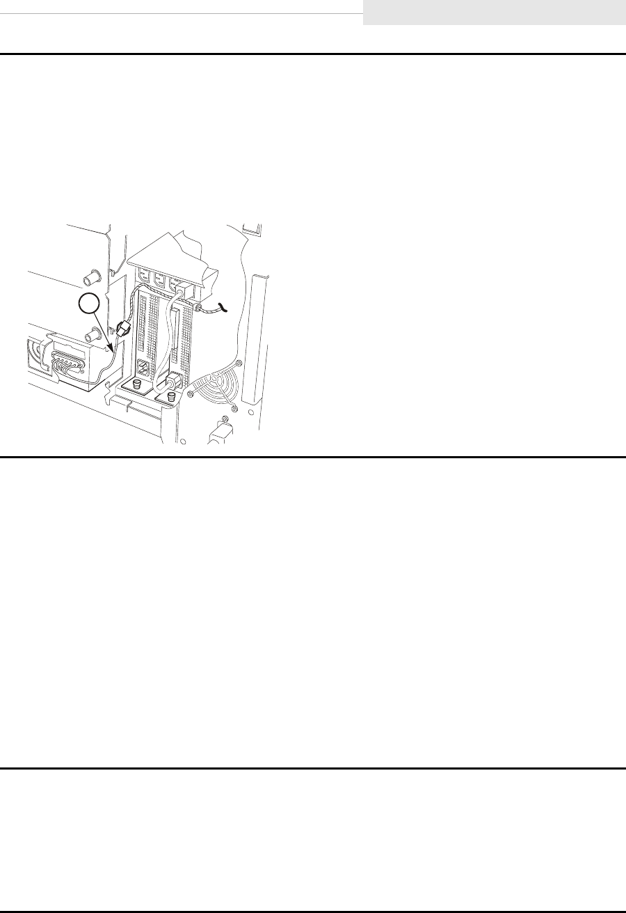
95741 Sixth Edition 3-13
9738 Library Attachment
Install Host Interface Cables
The 9840 supports FC and SCSI interfaces. Refer to:
•“9738 Fibre Channel Cable(s)”
•“9738 Library SCSI Cable(s)” on page 3-16
9738 Fibre Channel Cable(s)
Use the instructions below to attach Fibre Channel drives to the 9738 Library:
CAUTION:
Cable damage. Fiber-optic cables are easily damaged. Follow the
guidelines in “Fiber Optic Safety” on page 2-5 to prevent damage to the
cables.
6. Connect the plug of the TTI cable to the drive (see figure).
a. P983 goes to drive 0.
b. P982 goes to Drive 1.
c. P981 goes to Drive 2.
7. Repeat Step 6 for remaining drives.
1. TTI cable
1. Mark each FC cable with the drive position number, device address, and port.
2. Route the cable(s) from the host, hub or switch to the 9738 library.
Note: Do not connect either end of the cables at this time.
3. Remove the rubber port plug from the selected drive port.
4. Remove the cable connector covers and clean the cable ends with wipes.
E5325
1
1
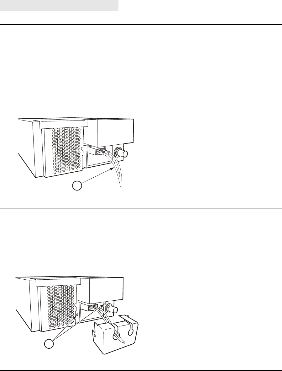
9738 Library Attachment
3-14 Sixth Edition 95741
CAUTION:
Equipment damage. Do not force the fiber-optic plug into the connector.
5. Connect the FC cable to the desired port on the rear of the tape drive (see the figure
below).
a. Port A is on the left side.
b. The connector is keyed so the cable can only be inserted one way.
6. Repeat Steps 3 through 5 if you will be using both ports of the drive.
1. Fibre Channel Cable
7. Locate the metal port enclosure.
8. Route the FC cable(s) through the appropriate hole of the enclosure.
9. Fasten the metal enclosure to the drive with two screws.
Note: To maintain the agency verification status of the product, you must attach the FC
port enclosure when using FC drives.
1. Mounting screw location (2X)
C5381
5
1
C53816
1
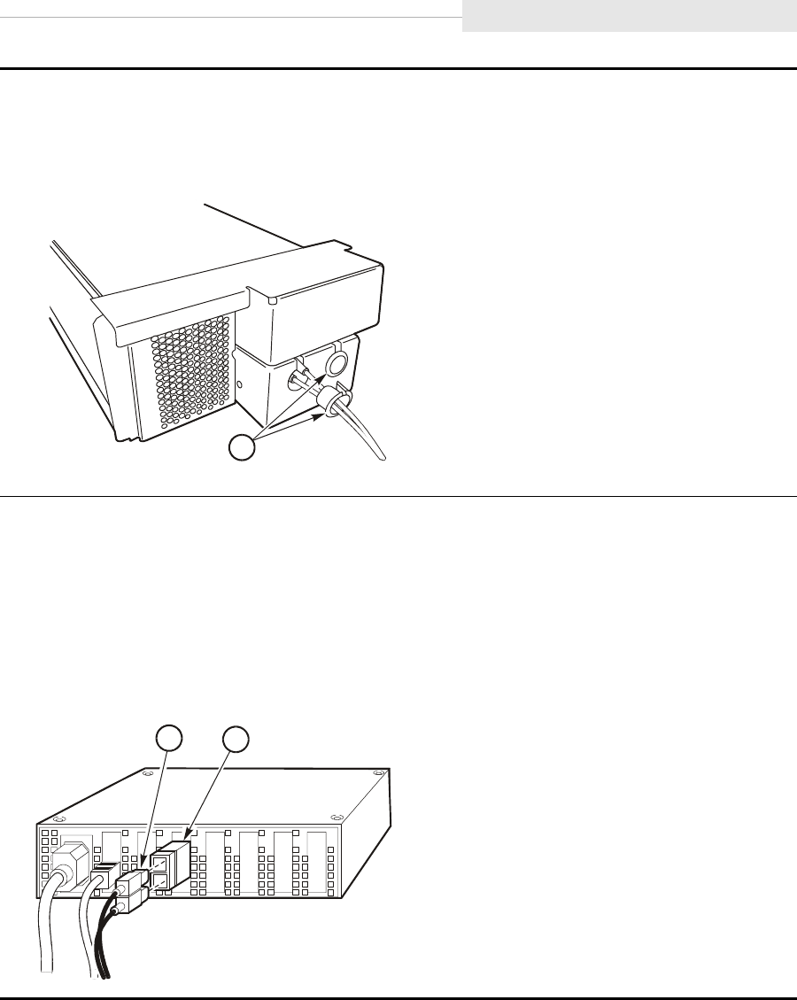
95741 Sixth Edition 3-15
9738 Library Attachment
10. Locate the grommets.
11. Slip a grommet over each installed FC cable.
12. Seat the grommet into the hole of the metal enclosure.
1. Grommets (2X)
13. Route the cable(s) to the hub or switch.
14. Remove the cable connector covers and clean the cable ends with wipes.
15. Connect the cable to an open port on the switch or hub.
16. Repeat Step 3 through Step 15, as applicable, for all other drives in the 9738 library.
17. Proceed to “Apply Power to Library Drive” on page 3-18 if you are only installing FC
drives.
1. Fibre Channel cable
2. Fibre Channel GBIC
C53817
1
C53530
2
1

9738 Library Attachment
3-16 Sixth Edition 95741
9738 Library SCSI Cable(s)
The 9840 Tape Drive connects to a SCSI bus and supports only the differential
alternative.
Note: Term power is not supplied by the 9840 Tape Drive, it must be supplied
by the host bus adapter card.
All host systems should have either the SCSI ports labeled or the international
symbols displayed (Figure 3-6 on page 3-16) to indicate the electrical
configuration for that port.
CAUTION:
Maximum cable length. The maximum cable length for the differential
alternative is 25 m (82 ft). Make sure that the total cable length (including
all daisy-chain cables) from the host to the last device does not exceed
the maximum length.
Use the following instructions to attach the SCSI drives to the 9738 Library:
Figure 3-6. SCSI International Symbols
1. Mark each SCSI cable with drive position number and the device address (SCSI ID),
information is used in Chapter 6, “Menu System.”
SINGLE-ENDED DIFFERENTIAL C5337
1
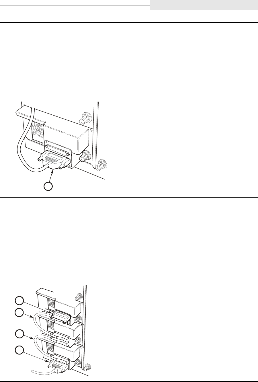
95741 Sixth Edition 3-17
9738 Library Attachment
CAUTION:
Connector damage. Be careful not to bend or damage the pins or connectors when
connecting the cable to the drive.
2. Connect the host SCSI cable to the lower 68-pin jack on the drive (see figure).
Note: You might want to connect the host SCSI cable to the 9738 library and daisy-chain
from the library to the 9840. If this describes your configuration, refer to the 9738
Product Manual for cabling instructions.
1. SCSI interface cable
3. If you are not going to daisy-chain drives, skip to Step 5.
Note: If you are daisy-chaining drives, locate a daisy-chain cable (PN 10083599)
in the hardware kit.
4. Connect one end of the cable to the top 68-pin jack on the drive tray, and connect the
other end of the cable to the bottom jack of the higher drive tray (see figure).
Note: If you are daisy chaining all three drives within the library, use another daisy-
chain cable and connect the upper 68-pin jack on the middle drive to the lower
68-pin jack on the upper drive.
1. Host interface connection
2. SCSI daisy-chain cable (Drive 0 to 1)
3. SCSI daisy-chain cable (Drive 1to 2)
4. SCSI terminator
E53252
1
C53370
4
3
2
1
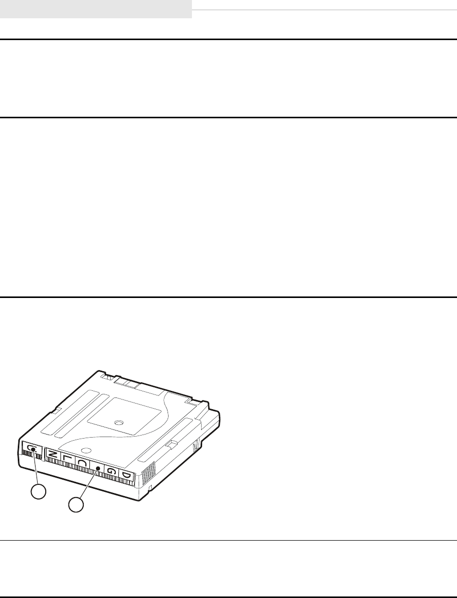
9738 Library Attachment
3-18 Sixth Edition 95741
Apply Power to Library Drive
1. Turn on the power switch of each 9840 Tape Drive power supply.
2. Connect the library power cord to a power source and enable the power
switch.
3. Verify that the drives power on.
Install a Cleaning Cartridge
Use the instructions below to apply the label to a cleaning cartridge:
5. Install the terminator (part number 10148003) either at the top jack at the rear of the
drive tray or to the device at the end of the SCSI bus.
6. Repeat steps 2 through 5, as they apply to the bus configuration, for any other drive.
7. Proceed to “Apply Power to Library Drive” on page 3-18.
1. Obtain the cleaning cartridge label.
2. Label a cleaning cartridge (identified by a “U” in the media ID area) by attaching a
DG CLN label to the VOLSER label area (see figure).
1. VOLSER label area
2. Media ID area
3. The cleaning cartridge will be installed in Column 0 Row 7. Refer to the 9738
documentation to enable auto cleaning.
4. Proceed to “Configure the Drive” on page 3-53.
C53373
1
2
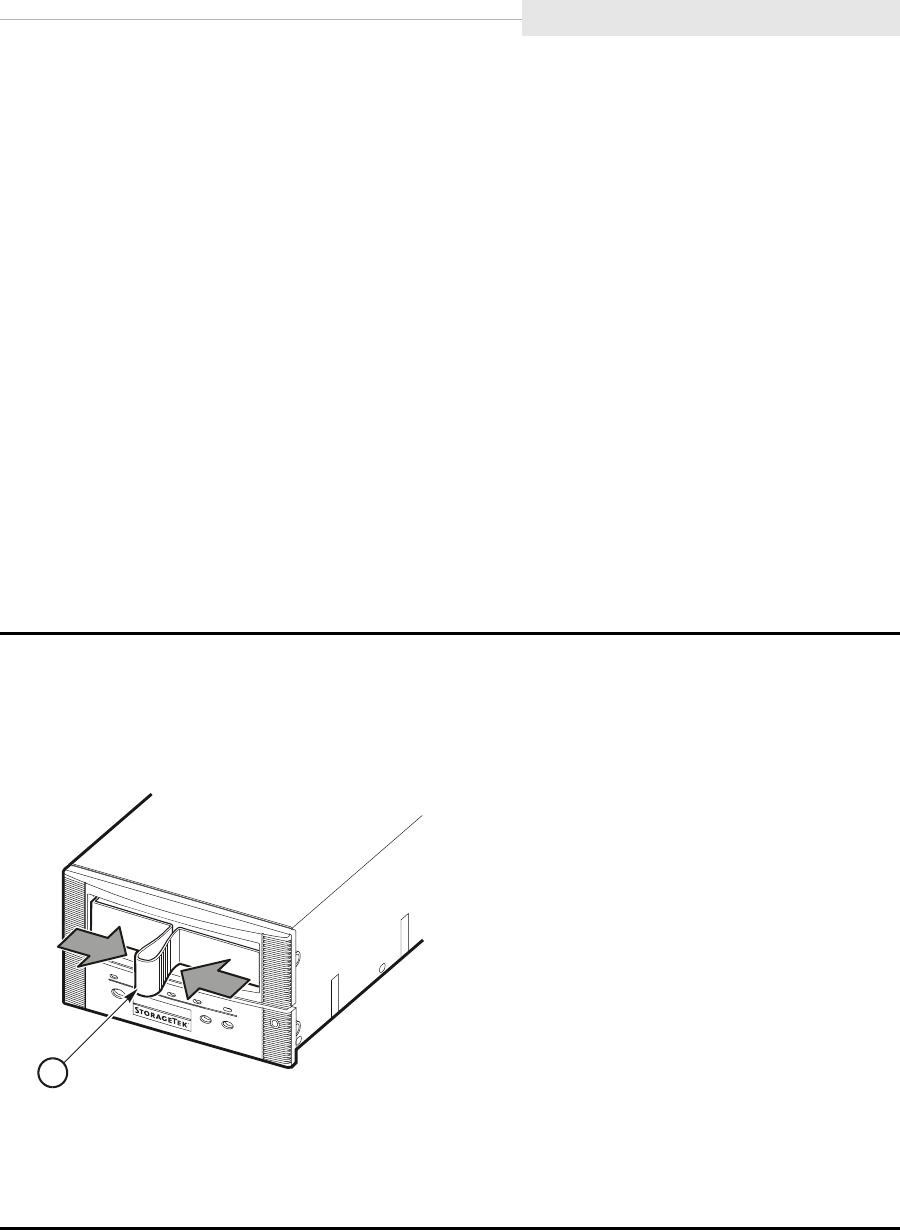
95741 Sixth Edition 3-19
Desktop Units
■Desktop Units
This section provides the installation procedure for the 9840 Tape Drive
desktop configuration. A desktop configuration contains either a manual mount
drive or a CSL. Fibre Channel or SCSI interfaces are available.
This section contains the following desktop procedures:
•“Desktop Drive Shipping Insert”
•“CSL Shipping Insert” on page 3-20
•“Install Host Interface Cables” on page 3-21
•“Power-On Desktop/CSL” on page 3-25
Desktop Drive Shipping Insert
Use the instructions below to remove the shipping insert from the drive:
Note: See “CSL Shipping Insert” on page 3-20 to remove the CSL shipping
insert.
1. Remove the shipping insert from the drive.
a. Squeeze both sides of the handle together.
b. Pull the shipping insert out from the drive.
1. Shipping insert
2. Store the shipping insert.
Note: The shipping insert should be installed in the drive whenever the Desktop Unit is
returned to StorageTek for any reason.
C53520
1
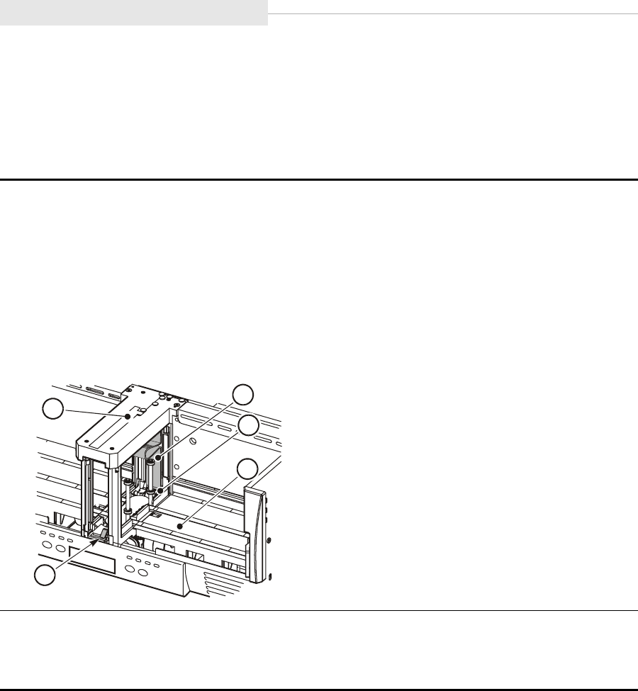
Desktop Units
3-20 Sixth Edition 95741
CSL Shipping Insert
Use the instructions below to remove the shipping insert from the CSL:
Note: See “Desktop Drive Shipping Insert” on page 3-19 to remove the
desktop drive shipping insert.
1. Locate the shipping insert within the feed channel.
2. Push the input bin bookend to right of the input bin and hold it in place.
3. Reach through the input bin and squeeze the shipping insert handle together.
Note: Squeezing the handle unlocks the shipping insert from the drive.
4. Slide the shipping insert out through the feed channel to the cartridge stop mechanism.
5. Push down on the cartridge stop mechanism and remove the shipping insert.
1. Feed channel
2. Shipping insert
3. Feed roller
4. Input bin
5. Cartridge stop mechanism
6. Store the shipping insert.
Note: The shipping insert should be installed in the drive whenever the CSL is returned to
StorageTek for any reason.
C5381
8
1
3
2
4
5

95741 Sixth Edition 3-21
Desktop Units
Install Host Interface Cables
The 9840 Tape Drive supports Fibre Channel and SCSI interfaces. This section
contains:
•“Fibre Channel Cables (Desktop/CSL)”
•“SCSI Cables (Desktop/CSL)” on page 3-23
Fibre Channel Cables (Desktop/CSL)
Use the instructions below to install the Fibre Channel cables:
CAUTION:
Cable damage. Fiber optic cables are easily damaged. Follow the
guidelines in Chapter 2, “Safety and Handling” to prevent damage to the
cables.
1. Mark each Fibre Channel cable with the device address and port.
2. Route the interface cable(s) from near the host, hub, or switch to the drive/CSL.
Note: Do not attach either end of the cable(s) at this time.
3. Remove the rubber port plug from the selected drive/CSL port and clean the port.
Note: If you are unfamiliar with the cleaning procedure, see “Clean Fibre Channel
Components” on page 8-4.
4. Remove the interface cable connector covers and clean the cable ends with wipes.
Note: If you are unfamiliar with the cleaning procedure, see “Clean Fibre Channel
Components” on page 8-4.
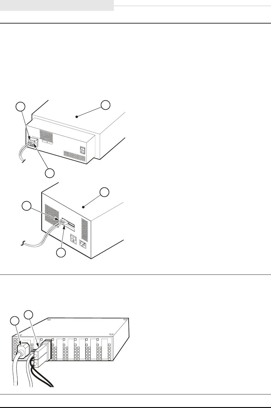
Desktop Units
3-22 Sixth Edition 95741
CAUTION:
Equipment damage. Do not force the fibre optic plug into the port connector.
5. Connect the Fibre Channel cable to the desired port on the rear of the tape drive/CSL.
Note: Port A is on the left side and Port B is on the right side of the drive/CSL. The
connector is keyed so the cable can only be inserted one way.
6. Repeat Steps 3 through 5 if you will be using both ports of the drive.
1. CSL
2. Desktop drive
3. Port A (Fibre Channel cable)
4. Port B (Fibre Channel cable)
7. Route the interface cable(s) to the hub or switch and connect to an open port.
Note: If you are connecting directly to a host, do not connect the cable at this time.
1. Fibre Channel cable
2. Power cord
8. Proceed to “Power-On Desktop/CSL” on page 3-25.
C53819
1
2
3
4
4
3
C53519
1
2

95741 Sixth Edition 3-23
Desktop Units
SCSI Cables (Desktop/CSL)
The 9840 Tape Drive/CSL connects to a SCSI bus and supports only the
differential alternative.
Note: Term power is not supplied by the 9840 Tape Drive, it must be supplied
by the host bus adapter card.
All host systems should have either the SCSI ports labeled or the international
symbols displayed (refer to Figure 3-7) to indicate the electrical configuration
for that port.
Use the instructions below to install the SCSI cables to the desktop drive or
CSL.:
CAUTION:
Maximum cable length. The maximum cable length for the differential
alternative is 25 m (82 ft). Make sure that the total cable length (including
all daisy-chain cables) from the host to the last device does not exceed
the maximum length.
Figure 3-7. SCSI International Symbols
1. Mark each cable with the drive position number and device address.
2. Route the cable(s) from near the host to the vicinity of the desktop drive.
Note: Do not attach either end of the cable(s) at this time.
SINGLE-ENDED D
IFFERENTIAL
C5337
1
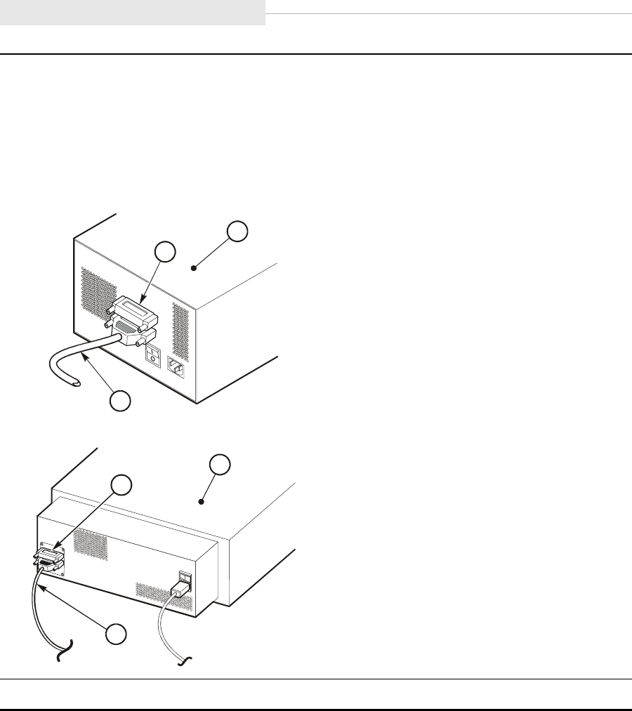
Desktop Units
3-24 Sixth Edition 95741
CAUTION:
Connector damage. Be careful not to bend or damage the pins or connectors when
connecting the cable to the drive.
3. Connect the host SCSI cable to the lower 68-pin jack at the rear of the drive/CSL.
4. Install the terminator (part number 10148003) on the device at the end of the SCSI bus.
1. Desktop drive
2. CSL
3. SCSI terminator
4. SCSI cable
5. Proceed to “Power-On Desktop/CSL” on page 3-25.
C53820
3
2
4
3
1
4
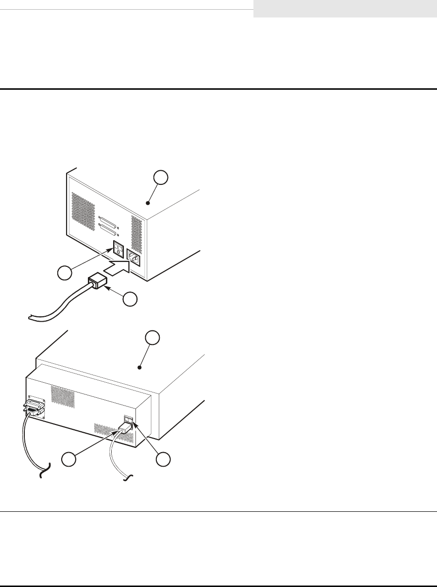
95741 Sixth Edition 3-25
Desktop Units
Power-On Desktop/CSL
Use the instructions below to power-on the 9840 desktop drive or the CSL:
Note: Ensure the female end of the power cord is plugged into the drive/CSL.
1. Attach the male end of the power cord to a power outlet.
2. Press the power switch on the 9840 Tape Drive/CSL.
1. Desktop drive
2. CSL
3. Power switch
4. Power cord
Note: The desktop drive and CSL shown above use a SCSI interface to the host.
3. Verify that the 9840 Tape Drive powers on.
Note: A steady asterisk on the operator panel indicates a successful IPL completion, the
drive is online, but not loaded with a cartridge.
4. Proceed to “Configure the Drive” on page 3-53.
1
4
3
C5382
1
3
2
4

Rack
3-26 Sixth Edition 95741
■Rack
The instructions provided here are specific to the StorageTek model number
RACK001. Six 9840Rxx Tape Drive rack-mount trays, six 9840Sxx CSL trays, or a
combination of both can be installed in a rack.
Note: Install the RACK001 stabilizer before you insert a 9840R/9840S tray.
If you are using a different rack, make sure it does not have a front door. The
instructions provided may not apply exactly to a different rack.
This section contains the following rack information:
•“Rack Safety and Precautions”
•“Installation Overview” on page 3-27
•“Tools Required” on page 3-28
•“Install Stabilizer” on page 3-28
•“Install Captive Nuts and Nut Plates for First Tray” on page 3-30
•“Install Slide Rails” on page 3-33
•“Additional Tray Rack-hardware Installation” on page 3-35
Rack Safety and Precautions
WARNING:
Possible personal injury:
•The dual drive 9840R weighs 22.7 kg (50 lb) and the 9840S weighs
18.6 kg (41 lb) with tray slides. To install the unit into a rack or
remove the unit from a rack might require more than one person.
•When you slide a drive unit out of the rack, you shift the rack’s center
of gravity. Ensure the rack is stable enough to withstand this shift.
Observe the following safety precautions when you install 9840R or 9840S trays
in the StorageTek RACK001:
•Do not allow rack elements to interfere with the tape drive’s ventilation.
The rack’s internal ambient temperature should not exceed the
recommended operating temperature range of the 9840Rxx/9840Sxx.
•Ensure that the combination of the 9840Rxx/9840Sxx with other
equipment in the rack does not create an overcurrent condition in the
power source. The combination of equipment in the rack must not
exceed the rating plate amperage of the power distribution strip and/or
the rated amperage of the facility’s branch circuit.
•Ensure that all equipment in the rack has reliable earth ground, whether
the equipment is connected directly to the branch circuit or to a power
distribution strip.
Note: The 9840R and 9840S rely on the ground pin of the power cord
for their earth ground.
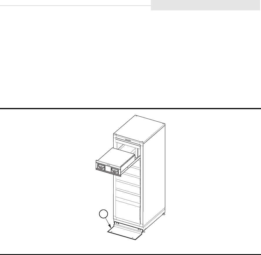
95741 Sixth Edition 3-27
Rack
Installation Overview
CAUTION:
Equipment damage. The RACK001 is only intended for the 9840 drive or
CSL trays. Any other equipment plugging into the rack power strip must
be approved by StorageTek and the appropriate safety agencies.
Figure 3-8 provides an overview of the rack installation and the location of the
stablizer.
The rack ships with the following items installed:
•A 2 EIU (88.5 mm/3.48 in.) filler at the top of the rack
•Five 4 EIU (177 mm/6.97 in.) fillers in drive tray locations two through six
•A 9 EIU (398 mm/15.7 in.) filler at the bottom of the rack
•Fan tray at the rear of the rack
•Power Distribution Unit (power strip) at the rear of the rack
There is an opening below the upper filler where the first drive or CSL tray will
be installed. To install additional trays, you must remove the filler plates.
Figure 3-8. Rack Installation Overview
1. Stabilizer
C53253
1
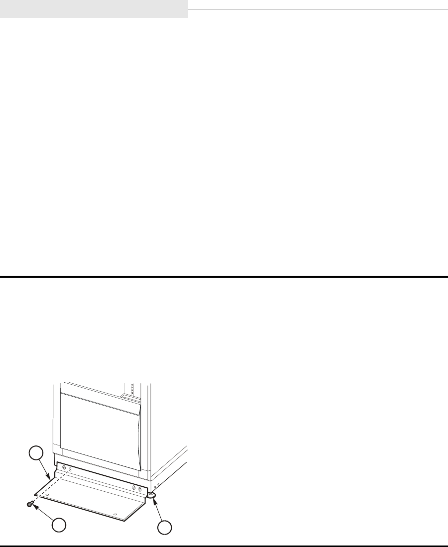
Rack
3-28 Sixth Edition 95741
CAUTION:
Equipment damage. Do not attempt to move the rack once drive or CSL
trays are installed. To prevent damage to the rack, you must remove all
drive/CSL trays and the stabilizer before relocating the rack.
Tools Required
The following tools are required to complete this installation:
•1/2 in. open-end wrench
•3/4 in. open-end wrench
•Assorted Torx screwdrivers
•Bubble level
Install Stabilizer
Use the instructions below to install the stabilizer plate on the rack:
1. Use a 3/4 in. wrench to lower the rack leveling pads, and while adjusting the pads use a
bubble level to verify the rack is plum and level.
2. Use a 1/2 in. wrench to install the stabilizer on the front of the rack.
Note: The stabilizer must remain connected to the rack. It should only be removed
when you are relocating the rack.
1. Stabilizer
2. Mounting screw (4X)
3. Leveling pad
C5325
5
1
3
2
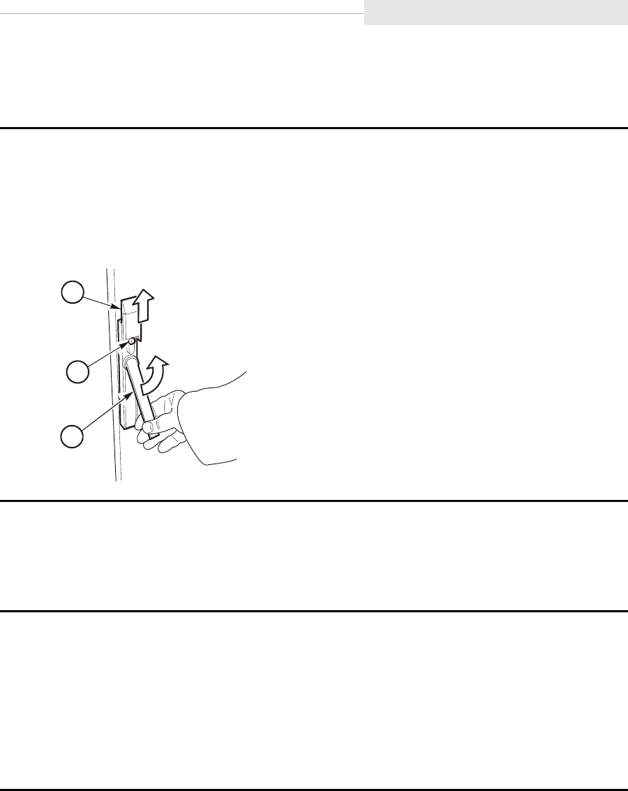
95741 Sixth Edition 3-29
Rack
Open the Rear Door
Follow the instructions below to open the rear door of the rack.
Install Optional Second Power Strip
Follow the instructions below to install a second power strip when more than
four trays are to be powered in the equipment rack.
1. Lift the lock shield (see figure below).
2. If locked, use the key to unlock the door.
3. Press on the key cylinder and the door handle pops out.
4. Turn door handle counter-clockwise to unlatch, and open door by pulling on the handle.
1. Lock shield
2. Key cylinder
3. Door handle
1. Unpack the power strip and mounting hardware.
2. If required, open the rack rear door.
3. Install captive nuts into holes 12 and 14, above the existing power strip.
Note: Make sure captive nuts are installed on both vertical frame members.
4. Position second power strip, and secure with four screws.
E53254
1
2
3
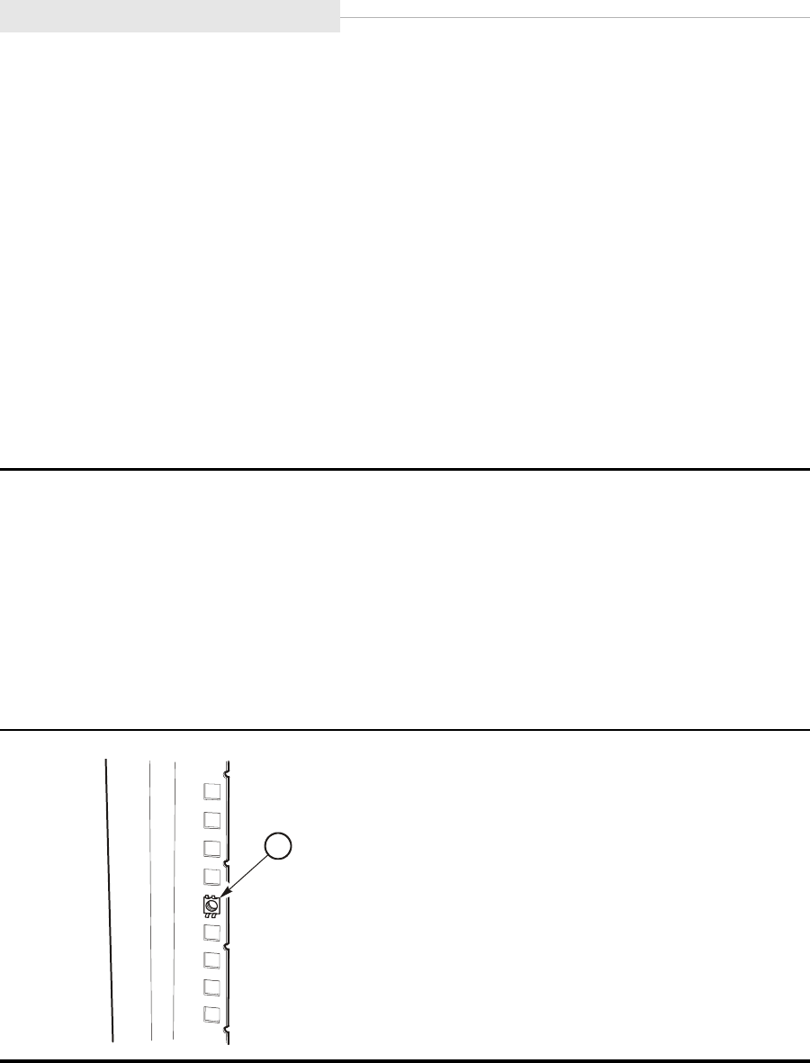
Rack
3-30 Sixth Edition 95741
Install Captive Nuts and Nut Plates for First Tray
Captive nuts are used to secure the tray to the rack while nut plates are used to
secure the slide-rail assemblies to the rack. The procedure for installing captive
nuts and nut plates is unique for each type of tray.
Install captive nuts and nut plates in the highest rack location by following the
appropriate procedure. The drive tray procedure follows below while the CSL
procedure begins on page 3-32.
If more that one tray is being installed in the rack, additional procedures are
available at “Additional Tray Rack-hardware Installation” on page 3-35.
Drive Tray Nuts and Nut Plates
Use the instructions below to install the drive tray captive nuts (PN 3000517xx)
and nut plates in the vertical frame members of the rack:
1. Locate the vertical frame members at the front of the rack.
2. Determine which holes the captive nuts are installed in. The drive tray uses holes 3 and
8 (counting down from the bottom edge of the upper spacer panel).
Note: The cabinet may ship with captive nuts installed in the correct locations.
3. Go to Step 5, if the captive nuts are installed in the correct location.
4. Place the bottom edge of the nut into the hole, use a tool to push down on the upper
edge of the nut, push the nut into the hole (see the following figure), and remove the
tool.
1. Captive nut
E53256
1
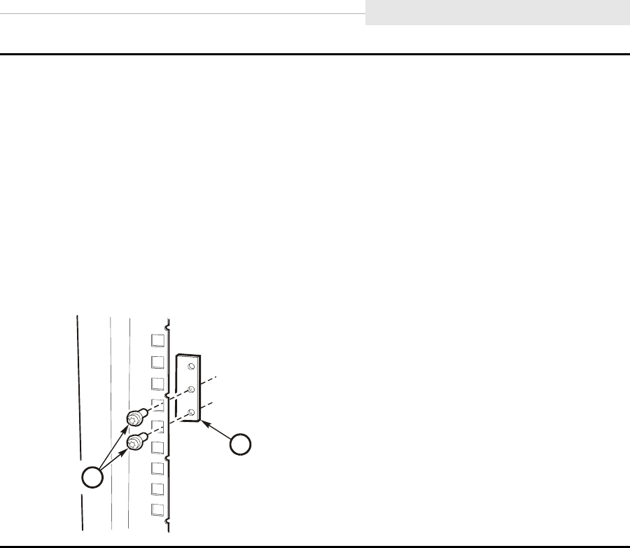
95741 Sixth Edition 3-31
Rack
5. Loosely attach nut plates for tray slide rails using two screws (see figure and instructions
below).
Note: Do not fully tighten the screws. The tray slide bracket will be inserted between
the nut plate and the vertical frame member in a later step.
a. At the front side of the cabinet, insert a nut plate into holes 10 and 11 (counting
down from the bottom edge of the upper spacer panel) of both vertical frame
members, and secure it with two screws.
b. At the rear of the cabinet, insert a nut plate into holes 10 and 11 (counting down
from the bottom of the fan tray) of both vertical frame members.
6. If you will not be installing CSL trays, go to “Install Slide Rails” on page 3-33.
1. Nut plate
2. Screws (2)
E53321
1
2
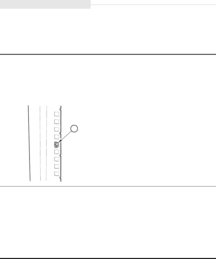
Rack
3-32 Sixth Edition 95741
CSL Tray Nuts and Nut Plates
Use the instructions below to install the CSL tray captive nuts (PN 3000517xx)
and nut plates in the vertical frame members of the rack:
1. Locate the vertical frame members at the front of the rack.
2. Determine which holes the captive nuts are installed in. The CSL tray uses holes 6 and 8
(counting down from the bottom edge of the upper spacer panel).
3. Place the bottom edge of the nut into the hole, use a tool to push down on the upper
edge of the nut, push the nut into the hole (see figure below), and remove the tool.
1. Captive nut
4. Loosely attach nut plates for tray slide rails using two screws (see figure and instructions
below).
Note: Do not fully tighten the screws. The tray slide bracket will be inserted between
the nut plate and the vertical frame member in a later step.
a. At the front side of the cabinet, insert a nut plate into holes 2 and 3 (counting down
from the bottom edge of the upper spacer panel) of both vertical frame members,
and secure it with two screws.
b. At the rear of the cabinet, insert a nut plate into holes 2 and 3 (counting down from
the bottom of the fan tray) of both vertical frame members.
E53256
1
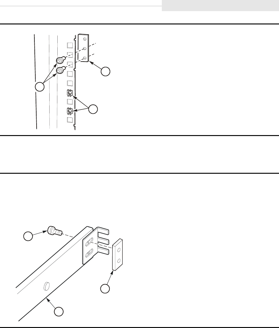
95741 Sixth Edition 3-33
Rack
Install Slide Rails
Use the instructions below to install the slide rails on the rack:
1. Screws (2)
2. Nut plate
3. Captive Nuts
1. Loosely attach the slide bracket to the rear of the slide-rail assembly using two screws
and nut plate (see figure below).
Note: Do not fully tighten the screws. You must adjust the slide bracket to fit the slide
rail between the vertical frame members.
1. Slide bracket adjustment screws (2)
2. Nut plate
3. Slide rail
C53680
1
2
3
C53257
3
1
2
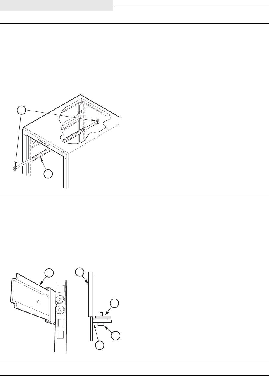
Rack
3-34 Sixth Edition 95741
2. At the front of the cabinet, insert the slide-rail assembly between the vertical frame
member and the nut plate.
3. Adjust the mounting bracket at the rear of the slide-rail assembly until it seats between
the nut plate and the vertical frame member.
4. Use a T-25 driver to tighten the 10-32 screws only enough to prevent the slide-rail
assembly from falling.
1. Slide-rail mounting screws (4)
2. Slide-rail assembly
5. Extend the slide rail out the front of the cabinet.
6. Position the slide rail so the center section clears the vertical frame member.
7. Tighten the nut plate screws.
8. Tighten the slide bracket screws at the rear of the slide assembly.
9. Repeat Steps 1 through Step 8 for the other slide assembly.
1. Slide rail
2. Nut plate
3. Screw
4. Slide clearance
10. Proceed to “Rack-mountable Tray” on page 3-38 if this is the only tray being installed.
C5325
8
2
1
C5350
7
11
2
3
4
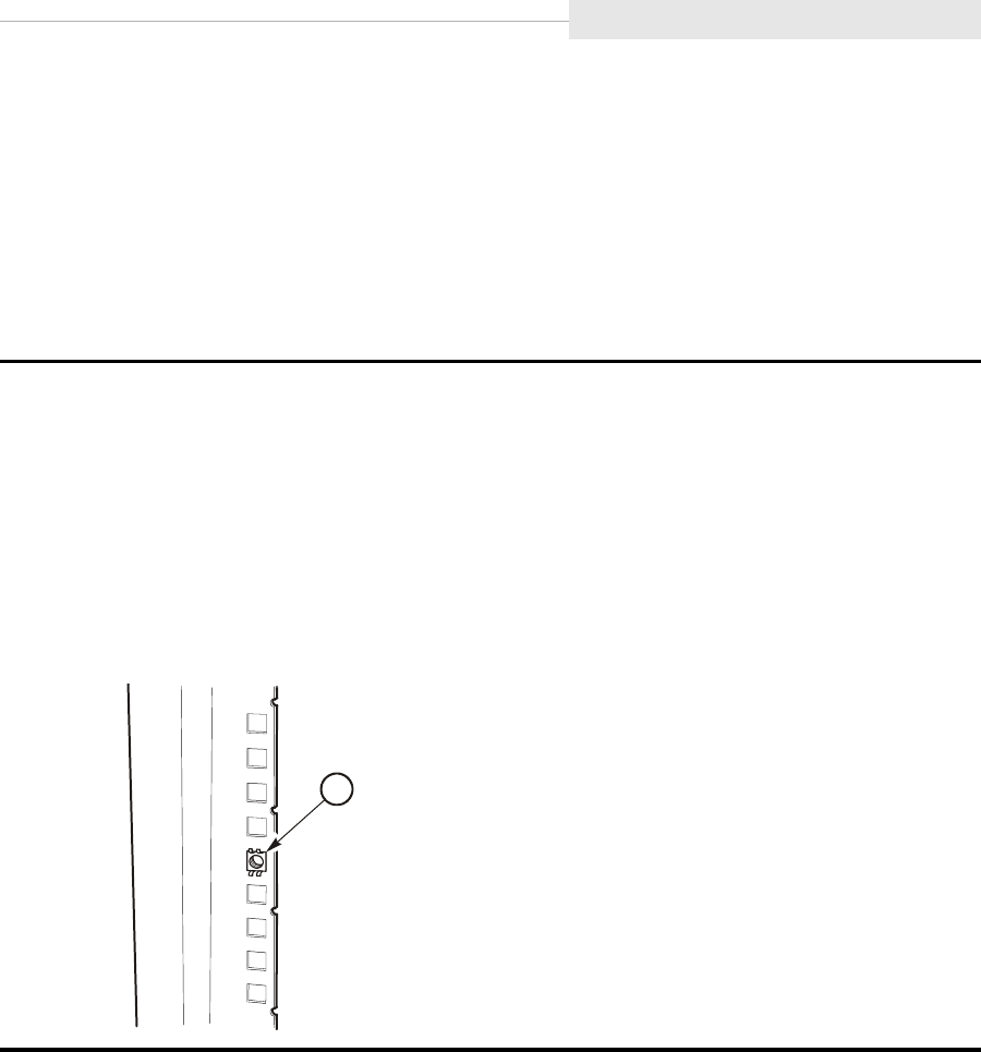
95741 Sixth Edition 3-35
Rack
Additional Tray Rack-hardware Installation
The instructions in this section are used when installing drive or CSL trays in
positions two through six on the RACK001. The drive tray instructions follow
below while the CSL instructions begin on page 3-37.
Drive Tray Additional Hardware
You will be removing a rack filler plate to enable installation of a drive tray.
1. Remove the decorative cover from the filler plate.
2. Remove the screws from the filler plate and remove the plate.
Note: The filler plate uses holes 3 and 10.
3. Reposition the captive nut from hole 10 to hole 8.
Note: Make sure to identify the starting point for numbering holes. You need to start
below the lowest point in the tray mounting plate. If you start immediately below
the slide-rail of the drive tray, the nut plate will be mounted too high.
1. Captive nut
E53256
1
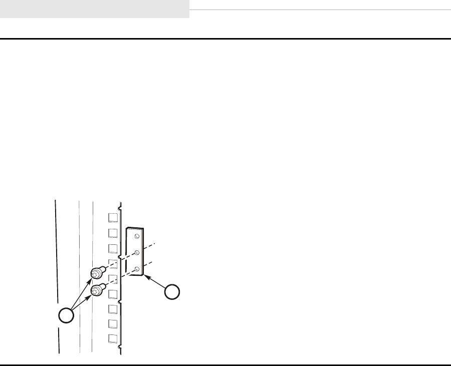
Rack
3-36 Sixth Edition 95741
4. Insert a nut plate at the front vertical frame members in holes 10 and 11 using two screws
(see the figure below).
Note: Only turn the screws until a few threads are in the nut plate. In a later step, the
slide-rail assembly will be inserted between the nut plate and the frame member.
5. Insert a nut plate at the rear vertical frame members in holes 10 and 11 using two screws.
6. Install slide rails by inserting them between the nut plates and vertical frame members.
7. Repeat Step 1 through Step 6 for each additional drive tray you will be installing.
8. Proceed to “Rack-mountable Tray” on page 3-38 if you will not be installing CSL trays.
1. Hand tool
2. Captive nut
E53321
1
2
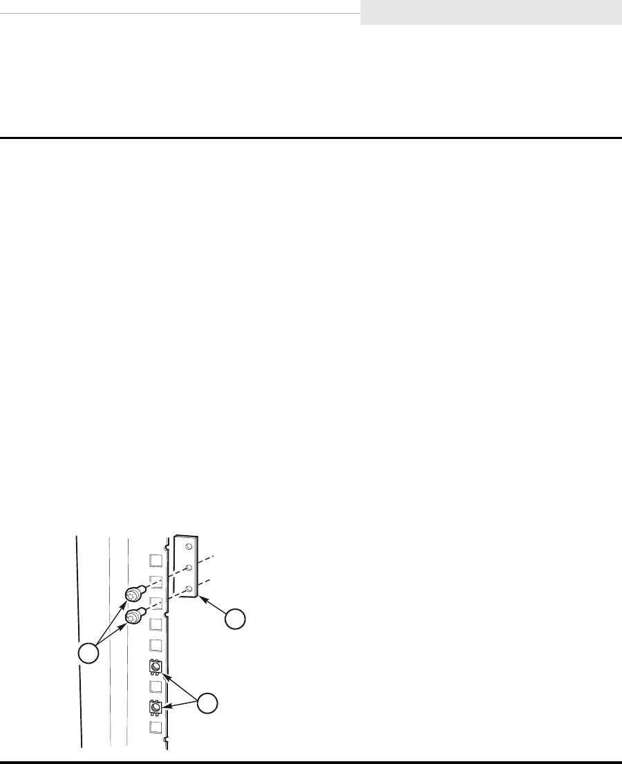
95741 Sixth Edition 3-37
Rack
CSL Tray Additional Hardware
You will be removing a rack filler plate to enable installation of a CSL tray.
1. Remove the decorative cover from the filler plate.
2. Remove the screws from the filler plate and remove the plate.
Note: The filler plate uses holes 3 and 10.
3. Reposition the captive nuts to holes 6 and 8.
Note: Make sure to identify the starting point for numbering holes. You need to start
below the lowest point in the tray mounting plate. If you start immediately below
the slide-rail of the drive tray, the nut plate will be mounted too high.
4. At the front of the cabinet, insert a nut plate into holes 2 and 3.
Note: Only turn the screws until a few threads are in the nut plate. In a later step, the
slide-rail assembly will be inserted between the nut plate and the frame member.
5. At the rear of the cabinet, insert a nut plate into holes 2 and 3.
6. Install slide rails by attaching them at holes 10 and 11.
7. Repeat Steps 1 through Step 6 for each additional CSL you will be installing.
8. Proceed to “Rack-mountable Tray” on page 3-38 if you will not be installing drive trays.
1. Screws (2)
2. Nut plate
3. Captive nuts
C53680
1
2
3

Rack-mountable Tray
3-38 Sixth Edition 95741
■Rack-mountable Tray
This section contains the following information:
•“Install Tray Rails”
•“Insert Tray” on page 3-40
•“Attach Tray Power Cord” on page 3-45
•“Install Host Interface Cables” on page 3-46
•“Power-On Rack” on page 3-52
Install Tray Rails
The instructions in this section describe how to install the drive tray rails on
both types of rack trays. The drive tray instructions follow below while the CSL
instructions begin on page 3-39.
Drive Tray Rail
Use the instructions below to attach the slide rail to a drive tray:
1. Remove the inner portion (drive-tray rail) of the slide-rail assembly.
2. Install rails on the bottom edge of a drive tray (see figure below).
Notes:
1. The spring latch faces away from the drive tray and toward the outside of the
tray. The spring latch must fit into the hole of the rack slide.
2. In later models, the spring latch is modified.
1. Drive tray rails (2)
2. Screws (5)
C53259
1
2
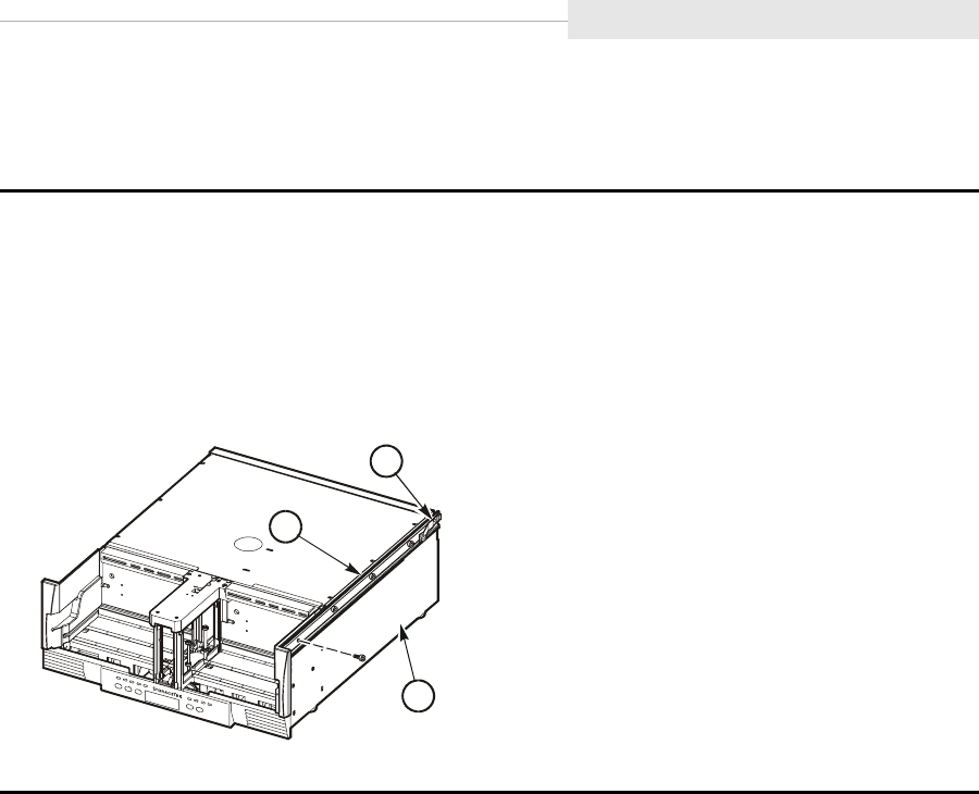
95741 Sixth Edition 3-39
Rack-mountable Tray
CSL Tray Rail
Use the instructions below to attach the slide rail to a CSL tray:
1. Remove the inner portion (drive-tray rail) of the slide-rail assembly.
2. Fasten rails on the top edge of the CSL tray (see the figure below) with screws.
Notes:
1. The spring latch faces away from the drive tray and toward the outside of the
tray.
1. Drive tray rails (2)
2. Screws (4)
C5368
1
1
2
3
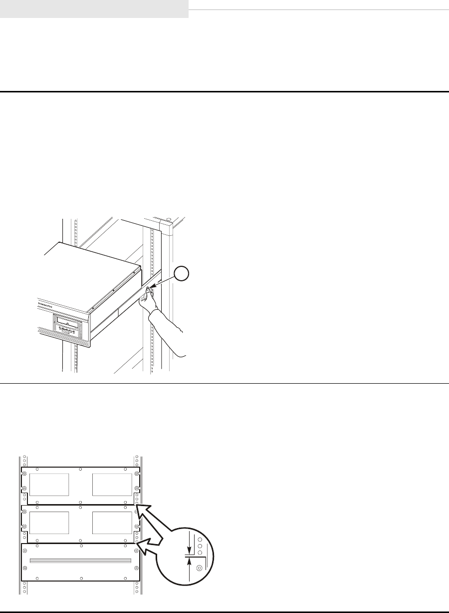
Rack-mountable Tray
3-40 Sixth Edition 95741
Insert Tray
Use the instructions below to insert and secure drive trays:
WARNING:
Heavy object. A single drive tray weighs 17.463 kg (38.5 lbs.), a CSL tray weighs 18.6
kg (41 lb), while a dual drive tray weighs 22.680 kg. (50.0 lbs.) Use two people when
inserting the drive tray into the slide-rail assembly.
1. Install the drive tray rails into the slide-rail assembly.
2. Press on spring latches, and push drive tray fully into the rack.
1. Spring latch
3. Ensure that the spacing between the mounting plates is 4 mm (.165 in.) as shown.
Note: You may need to loosen and reposition the front of the slide-rail assembly. This
spacing allows room for the decorative covers.
C53260
1
C53372
4 mm
(.165)
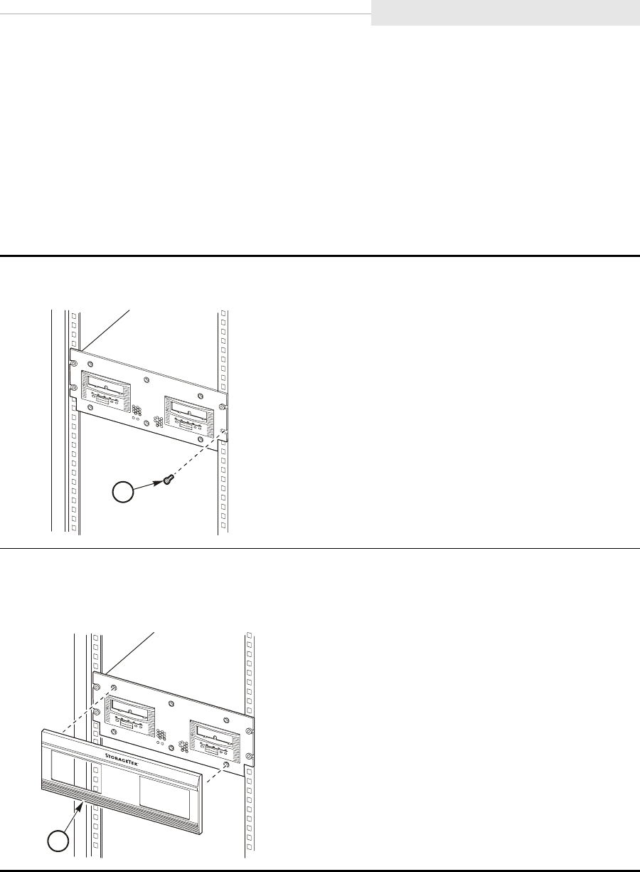
95741 Sixth Edition 3-41
Rack-mountable Tray
Secure Tray and Remove Shipping Insert
The instructions in this section describe how to secure trays to the rack and
remove the shipping insert from the drive cartridge aperture. CSL instructions
begin on page 3-43.
Drive Tray
Use the instructions below to secure a drive tray to the rack, apply the
decorative front cover, and remove the shipping insert:
1. Secure drive tray to rack with four 10-32 screws.
1. Drive tray mounting screws (4)
2. Install the drive tray decorative cover.
Note: If cover does not fit, reposition the slide-rail assembly.
1. Decorative cover
C5326
1
1
C53262
1
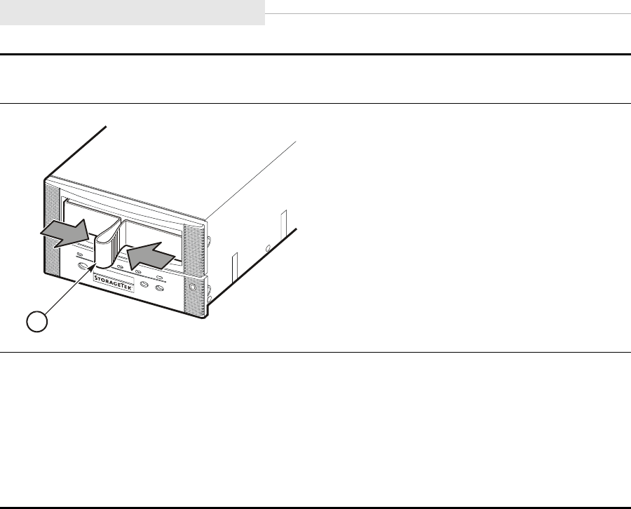
Rack-mountable Tray
3-42 Sixth Edition 95741
3. Remove the shipping insert by squeezing both sides of the handle together and pulling it
out from the drive.
1. Shipping insert
4. Repeat Step 3 if there is a second drive in the tray.
5. Store the shipping insert/s.
Note: The shipping insert should be installed in the drive whenever the drive tray is
returned to StorageTek for any reason.
6. Repeat Steps 1 through 5 for all remaining drives.
Proceed to “Attach Tray Power Cord” on page 3-45 if you will not be installing a CSL tray.
C53520
1
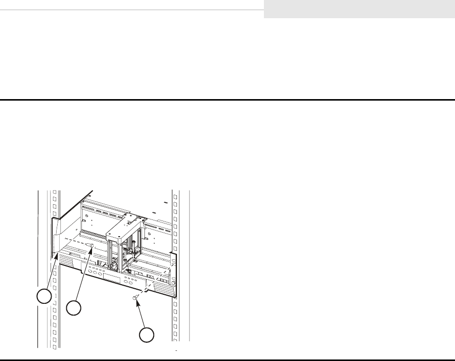
95741 Sixth Edition 3-43
Rack-mountable Tray
CSL Tray
Use the instructions below to secure a CSL tray to the rack, attach the side
panels, and remove the shipping insert:
1. Secure the CSL to the rack using four 10-32 screws. These screws mate with the captive
nuts installed in previous steps.
2. Add the decorative side panel to the output bin side of the CSL (see the following figure).
3. Repeat Step 2 for the input bin side of the CSL.
1. Side panel
2. Side panel mounting screw (2)
3. Drive tray mounting screws (4)
1
2
3
C53682
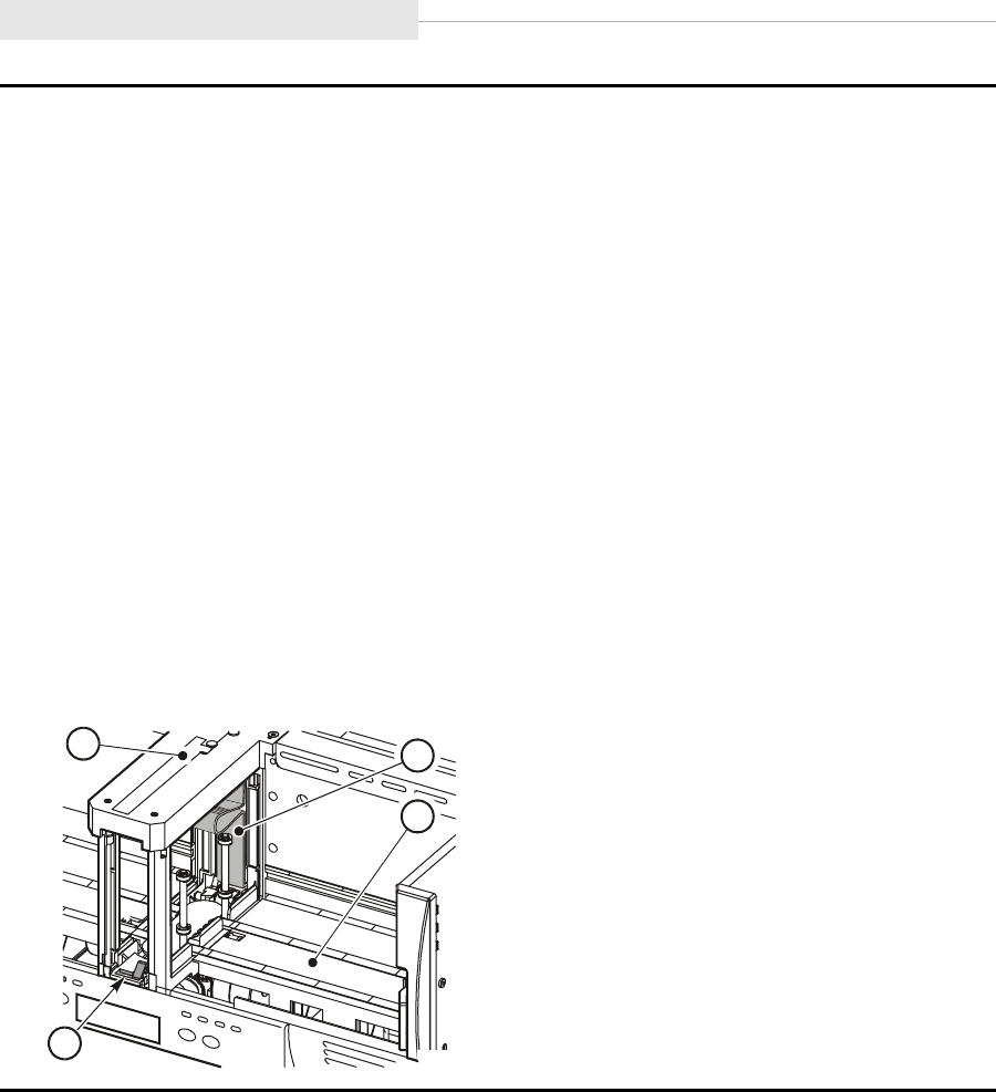
Rack-mountable Tray
3-44 Sixth Edition 95741
4. Remove the shipping insert (see figure) by performing these steps:
a. Move the input bin slider to the right and hold it in this position.
b. Reach through the CSL input bin to access the handle of the shipping insert.
c. Squeeze both sides of the handle together and pull it out from the cartridge loading
aperture.
d. Continue to pull on the shipping insert handle until it reaches the mouth of the feed
channel.
e. Release pressure on the input bin slider and return it to the extended position.
f. Press down on the cartridge stop mechanism at the base of the feed channel.
g. Grasp the handle of the shipping insert and pull it out of the feed channel.
5. Store the shipping insert.
Note: The shipping insert should be installed in the drive whenever the CSL tray is returned
to StorageTek for any reason.
6. Repeat Steps 1 through 5 if there are other CSL trays in the rack.
1. Feed channel
2. Shipping insert
3. Input bin
4. Cartridge stop mechanism
C53683
1
4
3
2
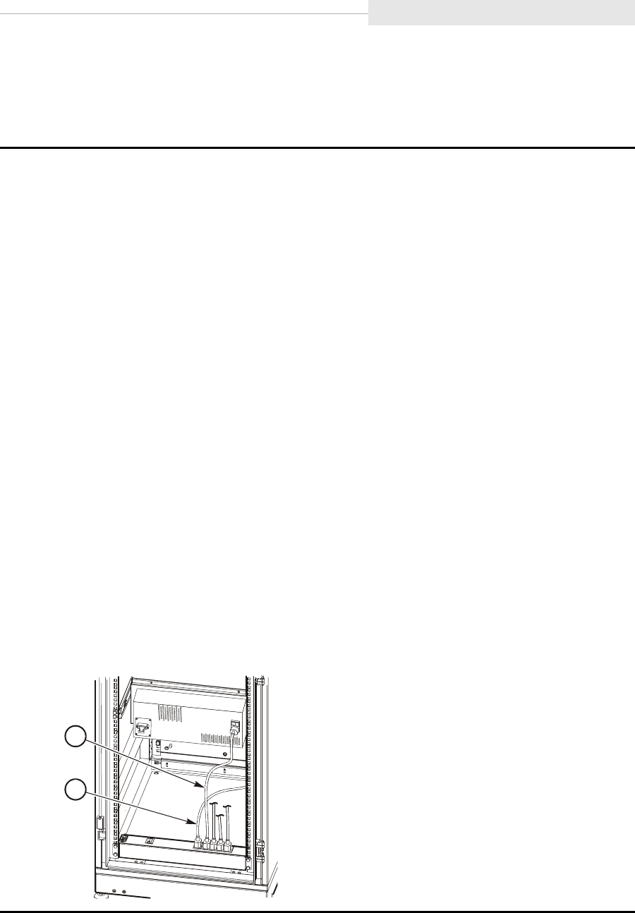
95741 Sixth Edition 3-45
Rack-mountable Tray
Attach Tray Power Cord
Use the instructions below to attach the power cord between a drive or CSL tray
and the rack power distribution unit (PDU) power strip:
1. Attach the female end of the power cord, part number 10083590, to the AC receptacle on
the tray.
Note: The figure shows the location of the receptacle on a CSL tray. The receptacle on a
drive tray is in a different location.
If you are not using StorageTek RACK001, a different power cord may be required
for the tray.
2. Attach the male end of the power cord to one of the 4-ganged outlets on the rack PDU
power strip.
Note: Earlier deliveries of StorageTek RACK001 may contain a PDU power strip which
has a 6-ganged outlet group.
3. Repeat Step 1 and Step 2 for all remaining CSL or drive trays.
Note: The RACK001 PDU power strip has a maximum of 12 Amps across the ganged
outlets available for powering trays.
The additional, single outlet is reserved for the rack fan power cord.
When installing more than four trays, a second PDU power strip must be obtained
and installed approximately 9 inches above the existing power strip (see “Install
Optional Second Power Strip” on page 3-29).
If you have the earlier, 6-ganged outlet PDU power strip, you should limit it to
powering a maximum of four trays, and obtain a second PDU power strip for
additional trays (see “Install Optional Second Power Strip” on page 3-29).
4. Slide the power cables into the brackets along the side of the frame.
1. Tray power cord
2. Fan power cord
1
2

Rack-mountable Tray
3-46 Sixth Edition 95741
Install Host Interface Cables
The 9840 Tape Drive supports Fibre Channel and SCSI interfaces. This section
contains:
•“Fibre Channel Cables (Rack-mount Tray)”
•“SCSI Cables (Rack-mount Tray)” on page 3-49
Fibre Channel Cables (Rack-mount Tray)
Use the instructions below to install Fibre Channel cables for a drive or CSL:
CAUTION:
Cable damage. Fiber optic cables are easily damaged. Follow the
guidelines in Chapter 2, “Safety and Handling” to prevent damage to the
cables.
1. Mark each Fibre Channel cable with the device address and port.
2. Route the cable(s) from near the host, hub, or switch to the rack.
Note: Do not attach either end of the cable(s) at this time.
3. Route the Fibre Channel cable(s) for the first drive tray through the floor tile cutout then
through the cable cutout in the floor of the rack, and up to the rear of the CSL or drive
tray.
4. Leave enough slack in the cable(s) to bend and connect to the drive port(s).
5. Remove the rubber port plug from the selected drive port and clean the port.
Note: If you are unfamiliar with the cleaning procedure, see “Clean Fibre Channel
Components” on page 8-4.
6. Remove the cable connector covers and clean the cable ends with wipes.
Note: If you are unfamiliar with the cleaning procedure, see “Clean Fibre Channel
Components” on page 8-4.
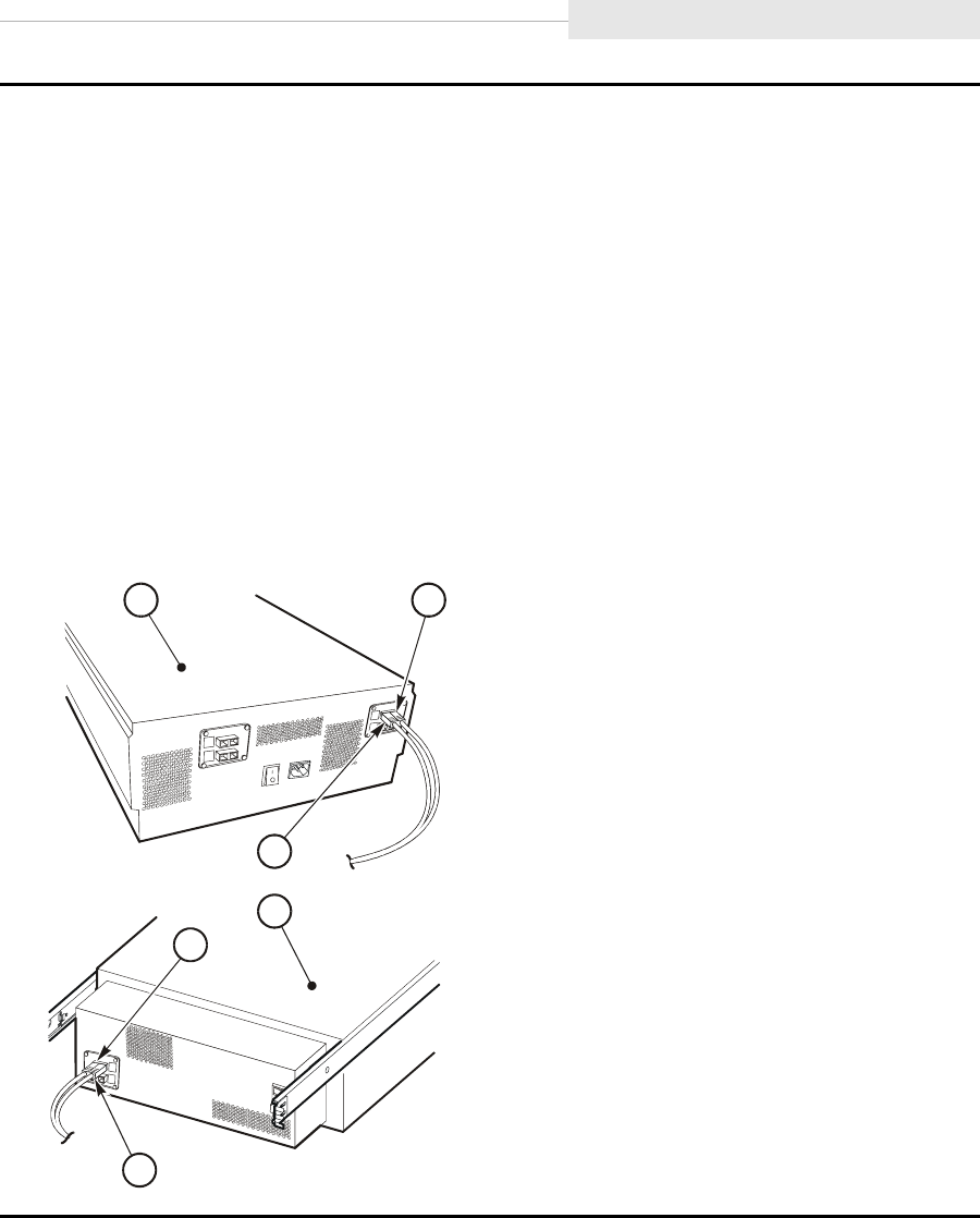
95741 Sixth Edition 3-47
Rack-mountable Tray
CAUTION:
Equipment damage. Do not force the fibre optic plug into the port connector.
7. Connect the Fibre Channel cable to the desired port on the rear of the tray.
Note: The connector is keyed so the cable can only be inserted one way.
CAUTION:
Cable damage. If slack is not maintained in the cable, the weight of the cable may
cause excessive stress at the cable connector.
8. Insert the cable into the cable brackets along the side of the frame. Make sure to provide
a drip loop to prevent stress at the cable connector.
9. Repeat Steps 3 through 8 if you will be using both ports of the drive.
Note: If the drive tray has a second drive, repeat Step 3 through 9.
1. Manual drive tray (two drives installed)
2. CSL drive tray
Note: Only one CSL can be installed
per tray.
3. Port A (Fibre Channel cable)
4. Port B (Fibre Channel cable)
C53822
2
3
3
1 4
4
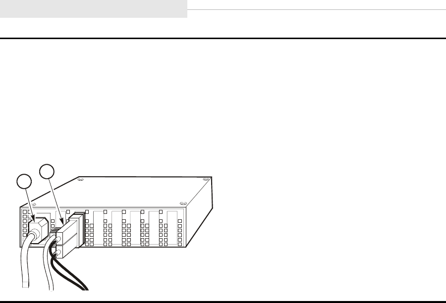
Rack-mountable Tray
3-48 Sixth Edition 95741
10. Route the cable(s) to the hub or switch and connect it to an open port.
Note: If you are connecting directly to a host, do not connect the cable at this time. This
will be done in a later section.
11. Repeat Step 3 through 10 for each additional Fibre Channel drive or CSL in the rack.
12. Go to “Power-On Rack” on page 3-52 if you are only installing Fibre Channel drive/CSL
trays.
1. Power cord
2. Fibre Channel cable
C53519
1
2

95741 Sixth Edition 3-49
Rack-mountable Tray
SCSI Cables (Rack-mount Tray)
The 9840 Tape Drive connects to a SCSI bus and supports only the differential
alternative.
Note: Term power is not supplied by the 9840 Tape Drive, it must be supplied
by the host bus adapter card.
All host systems should have either the SCSI ports labeled or the international
symbols displayed (Figure 3-9) to indicate the electrical configuration for that
port.
Use the instructions below to install SCSI cables for a drive or CSL:
CAUTION:
Maximum cable length. The maximum cable length for the differential
alternative is 25 m (82 ft). Make sure that the total cable length (including
all daisy-chain cables) from the host to the last device does not exceed
the maximum length.
Figure 3-9. SCSI International Symbols
1. Mark each cable with the device address; it is needed later to configure the drive/CSL.
2. Route the SCSI cable(s) from the host under the floor to the rack.
Note: Do not attach either end of the cable(s) at this time.
3. Route the SCSI cable(s) for the first tray through the floor tile cutout then through the
cable cutout in the floor of the rack, and up to the rear of the CSL or drive tray.
SINGLE-ENDED D
IFFERENTIAL
C5337
1
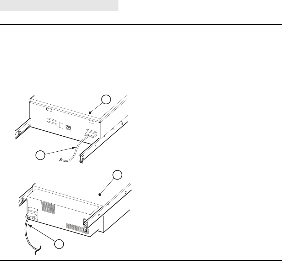
Rack-mountable Tray
3-50 Sixth Edition 95741
CAUTION:
Connector damage. Be careful not to bend or damage the pins or connectors when
connecting the cable to the drive or SCSI bus.
4. Connect the cable to the 68-pin jack on the drive (see figure).
5. Insert the SCSI cable into the cable brackets along the side of the frame.
1. Drive tray (two drives installed)
2. CSL tray
3. SCSI cable
C53264
3
3
1
2
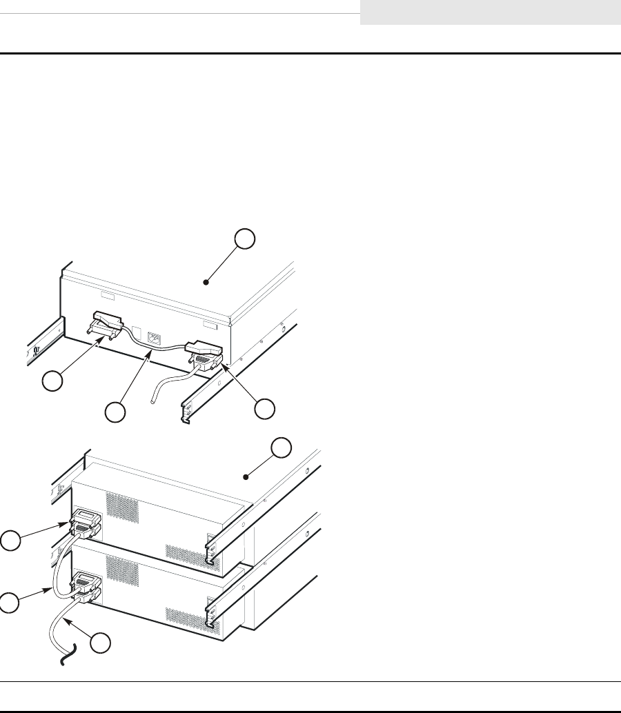
95741 Sixth Edition 3-51
Rack-mountable Tray
6. Connect the 457 mm (18 in.) daisy-chain cable (PN 310292001) from the second 68-pin
connector to the next drive, if applicable (see the CSL drive tray in the figure).
Note: Use a 343 mm (13.5 in.) daisy-chain cable (PN 10083616) for the manual-mount
drive tray.
7. Install a terminator (PN 10148003) on the device at the end of the SCSI bus.
8. Repeat Step 2 through Step 7 for all other CSL or drive trays.
1. Drive tray (two drive installed)
2. CSL tray
3. SCSI daisy chain cable
4. SCSI terminator
5. SCSI cable to host
9. Go to “Power-On Rack” on page 3-52 if you are only installing SCSI drive/CSL trays.
4
5
1
3
C5326
5
5
4
3
2
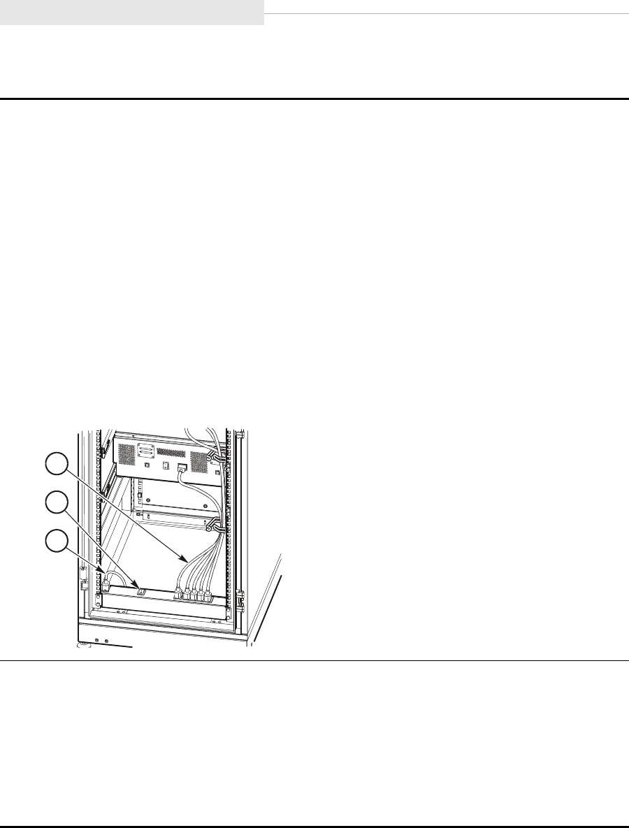
Rack-mountable Tray
3-52 Sixth Edition 95741
Power-On Rack
1. Make sure the rack fan power cord is connected to the single outlet of the rack PDU
power strip.
2. Attach the female end of the rack power cord to the connector on the left side of the rack
PDU power strip (see figure).
Note: When the RACK001 has more than four trays installed, a second PDU power strip
must be obtained and installed approximately 9 inches above the existing power
strip (see “Install Optional Second Power Strip” on page 3-29).
The second PDU power strip, if installed, must be powered by a separate power
cord and source.
3. Route the power cord/s through the floor of the rack, and attach the male end of the
power cord to a power source.
Note: To comply with safety agency standards, the socket/s shall be installed near the
equipment and shall be easily accessible.
1. Fan power cord
2. PDU power switch
3. Input power cord to rack PDU
4. Place the PDU power switch/es to the ON position.
5. Press the power switch on each installed tray to the ON position.
6. Verify that all installed trays are operational.
Note: A steady asterisk on the operator panel indicates a successful IPL completion, the
drive is online, but not loaded with a cartridge.
7. Proceed to “Configure the Drive” on page 3-53.
C535
5
1
2
3

95741 Sixth Edition 3-53
Configure the Drive
■Configure the Drive
After installation, make sure drive is properly configured as follows:
1. Obtain site specific configuration requirements.
2. Make sure the drive configuration settings match requirements.
Note: For change drive configuration guidance, refer to:
•“Fibre Channel Change Configuration Menu” on page 6-10
•“SCSI Change Configuration Menu” on page 6-24
3. Close any open doors and replace any access covers of the library or the
RACK001.
Table 3-3 provides a summary of configurable items.
Table 3-3. Fibre Channel and SCSI Configuration Items
Selection Fibre Channel SCSI
Compression Yes Yes
Data Security Erase Yes Yes
Port A/B Attributes1Yes N/A
SCSI Attributes1N/A Yes
Tape Bar Usage Yes Yes
Language Yes Yes
VolSafe Yes Yes
FullCode Load2No No
Emulation Yes Yes
Library Address3Yes Yes
CSL Power Up Mode Yes Yes
1 Fibre Channel and SCSI attributes must be set to match specific site
requirements.
2 Full code load is preset to “No”, and only applicable single firmware code is
loaded in the drive EEPROM prior to shipment from StorageTek. Refer to
FullCode Load Submenu, on page 6-18 or page 6-29 for additional FullCode
information.
3 Library address must be unique as required for specific site installation.

Install Interface Cables at Host
3-54 Sixth Edition 95741
■Install Interface Cables at Host
Install the free end of the interface cable (Fibre Channel or SCSI) to the
applicable hub, switch, or host.
CAUTION:
For SCSI cables, remove power from the 9840 Tape Drive before
connecting to the host.
Note: If you are attaching to a 50-pin SCSI bus, an adapter is required (part
number 10148010).
■Manually Load Cartridges
Test each installed drive to ensure it loads and unloads a cartridge correctly.
■Return System to Operator
After installation and testing of the 9840 Tape Drive. Follow these steps before
you turn the unit over to the customer:
1. Place the drive online (see Chapter 4, “Getting Started”).
2. Return to the 9738 library installation documentation and complete the
library installation, if applicable.
Note: The 9738 library configuration must be updated to identify 9840
Tape Drives.
3. If applicable, provide the operator with training on the 9840 Tape Drive.
4. If applicable, provide training on placing a service call.

95741 Sixth Edition 4-1
4
Getting Started
This chapter describes only the most common manual operations. It includes
instructions on operating the drive, and how to use the drive. This chapter
contains:
•“Basic Operations” on page 4-1
•“Clean the Drive” on page 4-5
•“Cartridges” on page 4-6
•“Format a Diagnostic Dump Tape” on page 4-10
•“Diagnostic Dump to Tape” on page 4-11
Note: Refer to Chapter 6, “Menu System,” for all drive operations.
■Basic Operations
This section provides instructions on:
•“Power-on the Drive”
•“Power-off the Drive” on page 4-2
•“Place the Drive Offline” on page 4-3
•“Place the Drive Online” on page 4-3
•“View Drive Configuration” on page 4-4
•“View Firmware Release Level” on page 4-4
Power-on the Drive
Note: Refer to Chapter 5, “Cartridge Scratch Loader,” for instructions to power-
on a CSL.
1. To apply power to a desktop unit and/or rack-mountable drive tray:
a. Make sure the power cord is connected to an AC source.
b. Set the Power switch on the rear panel to ON.
2. To apply power to a library drive power supply that has a Power switch:
a. Make sure the power cord is connected to a library power strip.
b. Set Power switch to ON.
3. To apply power to a library drive power supply that does not have a Power
switch, connect the power supply power cord to a library power strip.

Basic Operations
4-2 Sixth Edition 95741
4. Wait until the drive successfully completes IPL. Note the following:
•The “CC DIAGS” and “ASIA DIAGS” messages indicate that the IPL
diagnostics are active. These messages require no action on your part.
•The drive powers on automatically to online mode if drive is operable
and configuration error/s were not encountered.
•The drive powers on to offline mode if a configuration error was
encountered and the “Fix_CfgErr” message displays; see note.
•“Memory Err” or “Boot Fail” may be displayed if an error occurs
early in the IPL sequence. These errors cause the drive to hang; see
note.
Note: If any error displays, go to Table 7-2 on page 7-3 for a description of
corrective action.
5. Inform the operator when the drive is available and can receive I/O from
the host(s).
Power-off the Drive
Note: Refer to Chapter 5, “Cartridge Scratch Loader,” for instructions to power-
off a CSL.
1. Make sure I/O is not active to the drive from any host(s).
2. Unload a tape cartridge, if loaded, and remove it from drive.
3. Power-off the drive:
a. For a desktop unit and/or rack-mountable drive tray, set the Power
switch on the rear panel to OFF.
b. For a library drive power supply that has a Power switch, set the Power
switch to OFF.
c. For a library drive power supply that does not have a Power switch,
disconnect the power supply power cord.
Reset the Drive
Pressing the IPL switch resets the drive and reloads drive firmware into drive
memory. (The same process occurs automatically at power-on).
To reset a drive that is already powered on:
1. Make sure a cartridge tape is not loaded in the drive.

95741 Sixth Edition 4-3
Basic Operations
2. Press IPL.
-The
power indicator flashes.
- The display shows various messages indicating that the IPL is
proceeding. These messages require no action on your part.
When the drive finishes a successful IPL:
•The power indicator is on steadily.
•The display shows * (an asterisk).
•The drive is now in the online state.
Place the Drive Offline
By default, the drive is in the online state following a successful IPL. To change
the drive state to offline:
1. Cease all I/O activity from the host.
2. Press the Menu switch.
The display shows Online, indicating the current state of the drive.
3. Press Select to place the drive offline.
The display shows Offline, indicating a successful transition.
Note: While the drive is offline, other menu options are available. Refer to
Chapter 6, Menu System for additional instruction.
4. Press Menu until the display shows Exit Menu?.
5. Press Select to exit, or Menu to repeat Online/Offline selection.
Note: If Exit Menu? is selected, the display shows Offline,
alternating with the normal message, as a reminder that the drive is
in the offline state.
Place the Drive Online
To change the drive state back to online:
1. Press Menu.
The display shows Offline, indicating the offline state of the drive.
2. Press Select to place the drive online.
The display shows Online, indicating a successful transition.
3. Press Menu until the display shows Exit Menu?
4. Press Select to exit, or Menu to repeat the Online/Offline selection.

Basic Operations
4-4 Sixth Edition 95741
View Drive Configuration
To view current drive configuration:
1. Press Menu to enter the menu system.
a. If the display shows Online, go to step 2.
b. If the display shows Offline, press Select to place the drive online
2. Press Menu until the display shows View CFG ?.
3. Press Select to enter the view configuration submenus. The display shows
the first configuration setting.
4. Press Menu to step through the configuration settings.
5. Press Select to exit when the display shows Exit CFG ?,
or press Menu to repeat the view configuration submenus.
6. Press Menu until the display shows Exit Menu?
7. Press Select to exit the menu system, or press Menu to repeat the Online/
Offline selection.
View Firmware Release Level
To view the firmware release level:
1. Press Menu to enter the menu system.
2. Press Menu until the display shows a number in the following format:
Rx.yy.zzzc, where:
x is the major revision level
yy is the minor revision level
zzz is the integration number
c is the channel type, where
f is Fibre Channel
s is SCSI
3. Press Menu until the display shows Exit Menu?
4. Press Select to exit the menu system, or press Menu to repeat the Online/
Offline selection.

95741 Sixth Edition 4-5
Clean the Drive
■Clean the Drive
When the clean indicator on the operator panel (Figure 1-12 on page 1-11 or
Figure 1-13 on page 1-13 for the CSL) lights, it means that read/write errors
occurred or a specific length of tape has passed over the read/write head. The
9840 Tape Drive write/read head assembly should be cleaned by a cleaning
tape cartridge as soon as possible.
CAUTION:
Do not wet-clean (chemical-clean) a 9840 Tape Drive.
Do not clean the drive unless the clean indicator lights. Cleaning more
frequently might damage the read/write head.
Clean the drive with the drive offline or online. Use the 9840 cleaning cartridge
with the letter U in the media ID area (a dry-cleaning cartridge).
To clean the tape drive:
1. Unload the data cartridge tape if necessary.
2. Insert the cleaning cartridge in the drive.
Notes:
1. A CHK xxxx message means a cleaning cartridge failure, where the
notation “xxxx” is a four-character hexadecimal fault symptom code
(FSC). Try a different cleaning cartridge.
2. A 9840 cleaning cartridge is limited to 100 cleanings. If the drive
ejects the cleaning cartridge and displays Exp CLcart, the
cartridge is used up. Discard the cleaning cartridge and use a new
one.
3. Observe:
a. The green activity indicator flashes to indicate cleaning is occurring.
b. The cleaning cartridge ejects and the clean indicator turns off when
cleaning is complete.
4. Remove the cleaning cartridge.

Cartridges
4-6 Sixth Edition 95741
■Cartridges
This section provides the following cartridge information:
•“Write Protect/Enable a Cartridge”
•“Load a Cartridge Tape” on page 4-7
•“Unload a Cartridge Tape” on page 4-8
•“Reclaim (Reformat) a Cartridge Tape” on page 4-9
Write Protect/Enable a Cartridge
The 9840 Tape Drive uses standard and VolSafe cartridges. The VolSafe
cartridge can be distinguished from the standard cartridge by its yellow
markings.
Switch Positions
Refer to Table 4-1 for explanation of the write protect switch positions.
Process
Follow these instructions to write protect/enable a standard or VolSafe
cartridge:
1. Hold the cartridge with the customer label side up and rear volser label
towards you.
2. Locate the Write-protect switch on the right side of the cartridge (Figure 4-1
on page 4-7).
3. Move the switch to the front of the cartridge away from you for the write-
protect position, or in toward you for the write-enable position.
Table 4-1. Write Protect Switch
Write
Protect
Switch
Standard Cartridge VolSafe Cartridge
Unlocked Data can be written on the
cartridge.
Data can be read from the
cartridge.
Data can be appended to
written data on the cartridge.
Data can be read from the
cartridge.
Locked Cartridge is write protected.
Data can only be read from
the cartridge.
Cartridge is write protected.
Data can only be read from
the cartridge.
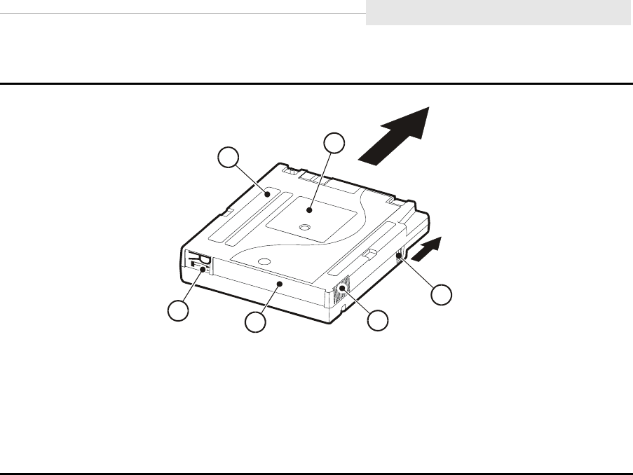
95741 Sixth Edition 4-7
Cartridges
Load a Cartridge Tape
Note: Refer to Chapter 5, “Cartridge Scratch Loader,” to load a cartridge tape
into a CSL.
1. Manually insert a cartridge tape into the drive loading slot in the direction
shown in Figure 4-1.
2. Observe the following messages on the display:
•Ready F (file protected) message means a write-protected cartridge
tape loaded successfully.
•Ready U (file unprotected) message means a write-enabled cartridge
tape loaded successfully.
•Ready A (append only) message means a write-enabled VolSafe
cartridge tape loaded successfully in a VolSafe-enabled drive.
•Load xxxx message means an attempted load was unsuccessful,
where “xxxx” is the FSC that caused the Load failure. See Table 7-2 on
page 7-3 to resolve this condition.
Figure 4-1. Cartridges
1. Manufacturer Label Area (yellow on VolSafe Cartridge)
2. Customer Label
3. Write Protect Switch (yellow on VolSafe Cartridge)
4. Finger Grips
5. VOLSER Label Area
6. Media Id (machine identifiable-yellow on VolSafe Cartridge)
C5367
8
WRITE
PROTEC
T
REAR VIEW
1
2
4
3
65

Cartridges
4-8 Sixth Edition 95741
Unload a Cartridge Tape
Note: Refer to Chapter 5, “Cartridge Scratch Loader,” to unload CSL cartridges.
Pressing the Unload switch causes the cartridge in the drive to rewind and eject.
Pressing Unload once during a write operation causes the drive to try to write
the remaining data before the cartridge tape unloads. A display of UnWr xxxx
(unwritten data, where xxxx is the FSC) means that some data is not written to
the tape. Pressing Unload a second time causes the unwritten data to be lost.
Before you press Unload again, see “UnWr xxxx Indication” on page 7-12
To unload a cartridge tape:
1. Make sure the drive is not reading, writing, or selected from the host.
CAUTION:
DATA LOSS. DO NOT PRESS Unload TWICE DURING A WRITE
OPERATION.
2. Press the Unload switch once
Note: One of the following conditions occurs:
• The cartridge tape rewinds and ejects from the drive.
Remove the cartridge tape from the drive.
• The cartridge tape rewinds but fails to eject. The display shows
Load xxxx, where xxxx is the FSC.
• The cartridge tape is jammed and the drive requires service to
resolve the problem (Refer to “Jammed Cartridge” on page 8-1).

95741 Sixth Edition 4-9
Cartridges
Reclaim (Reformat) a Cartridge Tape
A 9840 tape cartridge, specially formatted or corrupt, can be reformatted as a
data tape and returned (reclaimed) to normal use.
CAUTION:
Tape damage: Do not degauss a tape cartridge. A servo track is written
on the tape at the factory. Degaussing the tape erases this track and
renders the tape unusable and unrecoverable.
To reclaim a cartridge:
1. Ask the operator to make sure the drive does not have I/O to/from the host.
2. Press the Menu switch, then press Select for Offline.
3. Press the Menu switch until you reach the Drive Operations menu.
Drv Menu? displays.
4. Press the Select switch to enter Drive Operation submenus.
5. Press the Menu switch until MakeDataTp displays.
6. Press the Select switch to start.
Note: Any tape cartridge in the drive ejects.
7. Load a write-enabled tape cartridge when Ld Data Tp displays.
Notes:
•Formatting starts automatically.
•The green activity indicator flashes during the process.
•The process erases previous data and reformats tape.
•If DatCrFailx (where x=1) displays, an error has occurred. See
Table 7-2 on page 7-3.
•When formatting is done, the tape cartridge ejects.
8. Remove the tape cartridge.
Note: To format another data tape, repeat Steps 7 and 8.
9. Exit the Drive Operations menu.
10. Return the drive to Online.
11. Exit the Menu system.
Note: A steady * should display after exiting.
12. Inform the operator that the drive is ready.

Format a Diagnostic Dump Tape
4-10 Sixth Edition 95741
■Format a Diagnostic Dump Tape
Use the following procedure to format a 9840 tape cartridge with a special
format that prepares it to collect a diagnostic dump.
1. Ask the operator to make sure the drive does not have I/O to/from the host.
Note: In the enterprise environment, ask the operator to vary the drive
offline.
2. Press the Menu switch, then press Select for Offline.
3. Press the Menu switch until you reach the Drive Operations menu.
Drv Menu? displays.
4. Press the Select switch to enter Drive Operation submenus.
5. Press the Menu switch once. The MakeDumpTp submenu displays.
6. Press the Select switch to start.
Note: Any tape cartridge in the drive ejects.
7. Load a write-enabled tape cartridge in the drive when Ld Dump Tp
displays.
Notes:
•Formatting starts automatically.
•The green activity indicator flashes during the process.
•The process erases previous data and gives the tape cartridge a
special dump tape ID coding.
•If DmpCrFailx displays (where x=1 or 2), an error has occurred.
See Table 7-2 on page 7-3.
•When formatting is done, the tape cartridge ejects.
8. Remove the tape cartridge.
Note: To format another dump tape, repeat Steps 7 and 8.
9. Exit the Drive Operations menu.
10. Return the drive to Online.
11. Exit the Menu system.
Note: A steady * should display after exiting.
12. Inform the operator that the drive is ready.

95741 Sixth Edition 4-11
Diagnostic Dump to Tape
■Diagnostic Dump to Tape
Whenever an error occurs that creates diagnostic dump data, the red service
and green activity indicators on the operator panel flash, to indicate new
diagnostic data is being saved (dumped) to the EEPROM. Once the data is
saved, the indicators stop flashing. The display now alternates between an *,
and xxxx:Dmpyy, to indicate that a new uncollected dump is present and is
available to download (collect) to tape or electronic files.
Note: The notation “xxxx” is the FSC of the fault that caused the dump, and yy =
total number of uncollected dumps in the EEPROM.
Use the following procedure to collect diagnostic dump data from the drive
EEPROM to a specially formatted, write-enabled tape cartridge. If formatting a
tape is required, see “Format a Diagnostic Dump Tape” on page 4-10.
The dump to tape operation does not overwrite dumps already on the tape.
New dumps append to earlier dumps already on the tape.
To collect a diagnostic dump to tape:
1. Ask the operator to make sure the drive does not have I/O to/from the host.
2. Load a write-enabled, formatted dump tape in the drive.
Notes:
•Data is automatically written to the tape from the drive’s EEPROM.
•While data is being written to the tape, the green activity indicator
flashes.
•When the process is done, the dump tape cartridge ejects.
•If DmpWrFailx displays (where x=1 or 2), an error has occurred.
SeeTable 7-2 on page 7-3.
3. Remove the dump tape cartridge.
4. If drive is Offline, return it to Online.
5. Exit menu system.
Note: A steady * should display after exiting.
6. Inform the operator that the drive is ready.

Diagnostic Dump to Tape
4-12 Sixth Edition 95741
This page intentionally left blank.
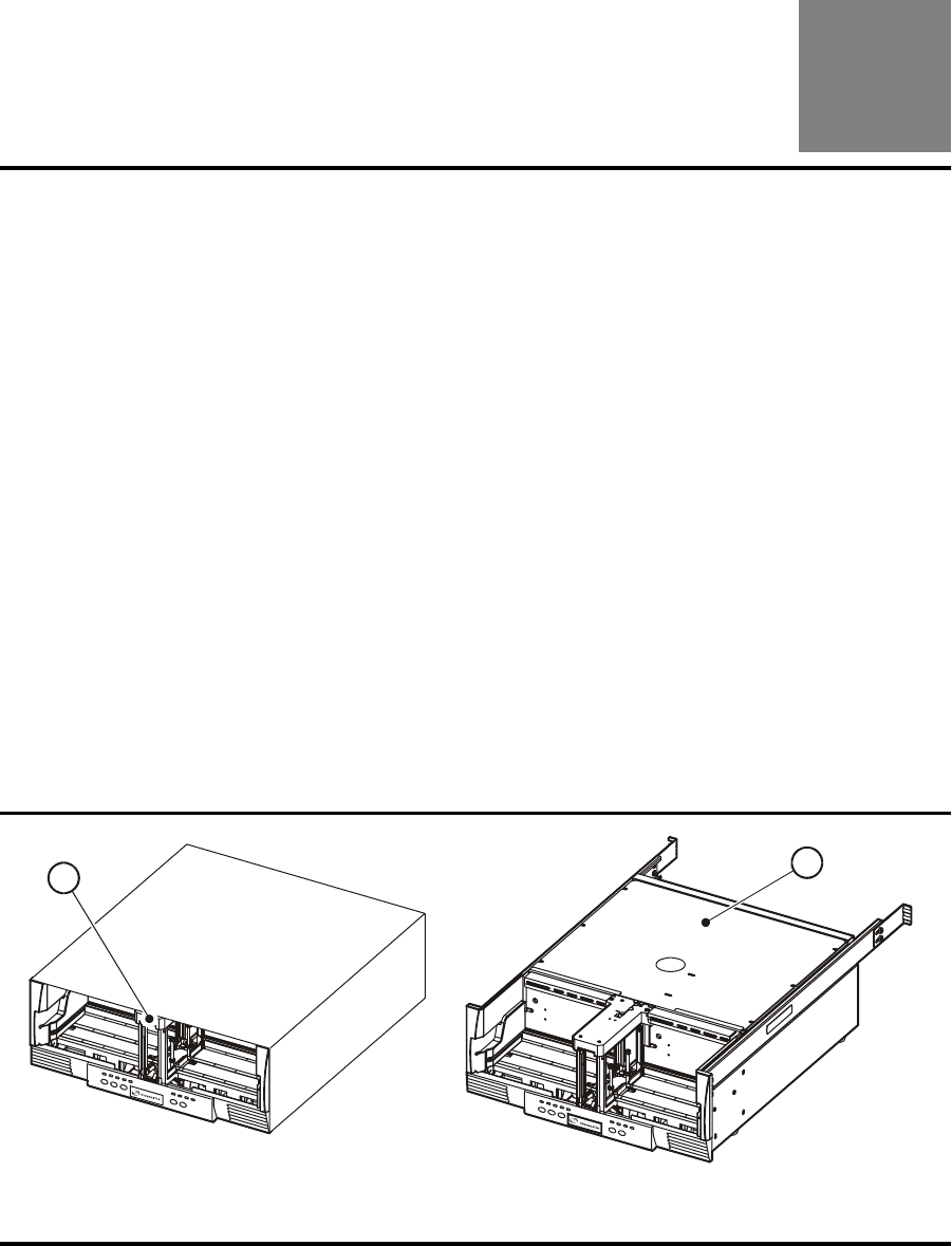
95741 Sixth Edition 5-1
5
Cartridge Scratch Loader
This chapter covers the Cartridge Scratch Loader (CSL). It contains:
•“Overview”
•“Desktop CSL” on page 5-5
•“Rack” on page 5-6
•“Rack-mount CSL Tray” on page 5-7
•“Operator Panel” on page 5-8
•“Power On/Off CSL” on page 5-12
•“CSL Cartridge Loading/Unloading” on page 5-14
•“Modes of Operation” on page 5-16
•“Error and Recovery” on page 5-23
•“Jammed Cartridge” on page 5-30
•“Shipping Insert” on page 5-35
■Overview
The CSL consists of a 9840 Tape Drive, a power supply, and a scratch loader.
The CSL ships as a desktop or rack-mounted unit (Figure 5-1).
Note: Priority cartridges can be mounted in any mode of operation.
Figure 5-1. Desktop and Rack-mount CSL
1. Desktop CSL
2. CSL for rack-mount tray
C53823
2
1
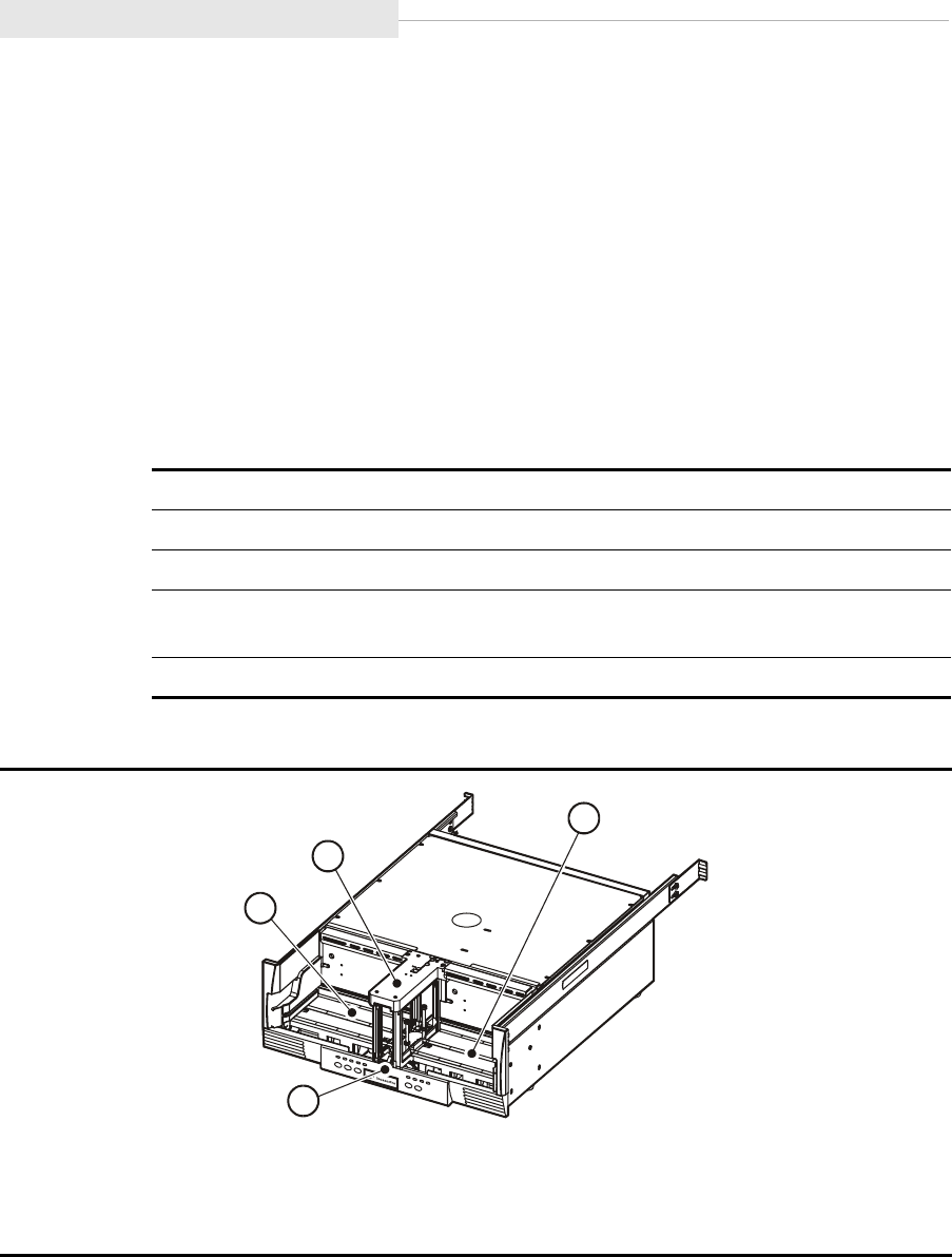
Overview
5-2 Sixth Edition 95741
The CSL is an electromechanical device that can load and unload up to seven
cartridge tapes. It also has a priority feed slot (open area of feed channel) to
mount a priority cartridge into the tape drive.
Component Locations
Refer to Table 5-1 for CSL component descriptions and to Figure 5-2 for
locations of the CSL components. Operators should become familiar with the
CSL components listed below.
Note: The CSL desktop and the rack-mountable 19 inch tray unit (Figure 5-1
on page 5-1) components and locations are identical.
The client-server CSL desktop and the rack-mountable version use Fibre
Channel and SCSI interfaces. The interface cable, power cord, and power
switch are located on the rear of the unit. Figure 5-5 on page 5-6 illustrates the
rack mount CSL.
Table 5-1. CSL Component Descriptions
Component Purpose
Operator Panel Operates the 9840 Tape Drive and CSL
Output Bin Houses ejected cartridges from the feed channel
Feed Channel Inputs/outputs cartridges to/from 9840 Tape Drive and also
used for priority mounts
Input Bin Loads cartridges into the feed channel
Figure 5-2. CSL Component Locations
1. Input Bin
2. Operator Panel
3. Output Bin
4. Feed Channel
C53657
1
3
4
2
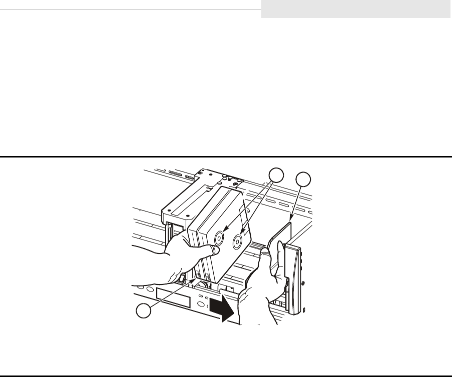
95741 Sixth Edition 5-3
Overview
Cartridge Routing
Cartridges are loaded into the CSL (Figure 5-3) vertically with the Media Id label
(R) facing out towards the operator (reels to the right). Load cartridges into the
input bin (right side of the CSL).
Note: Never load cartridges flat or with the cartridge reels to the left.
Figure 5-2 on page 5-2 provides all components of the CSL. The output bin is
located on the left side of the CSL. The feed channel is in the middle of the CSL.
Cartridges are shifted from the right to the left, from the input bin into the feed
channel and from the feed channel into the output bin.
Note: The CSL is unable to prevent or detect miss-oriented cartridges. Ensure
cartridges are always loaded correctly (Figure 5-3).
Cartridges are loaded into the drive as they are manually loaded by the
operator. If the drive detects an incorrectly positioned cartridge, it forces a CSL
failure condition or requests an unload operation from the CSL.
Figure 5-3. Cartridge Routing
1. Cartridge reels
2. Input bin bookend
3. Media ID label (R)
C5365
8
12
3

Overview
5-4 Sixth Edition 95741
CSL Firmware Update/Load
Drive code release 1.28.10x, and up, combines the latest CSL released code with
the 9840 Tape Drive code. The code load process is as follows:
Note: Drive code update/load must always be completed by a qualified
technician.
1. When the code tape is loaded, the code loads into the drive EEPROM.
2. When the drive is IPLd and if the drive is installed in a CSL, the CSL code is
checked.
3. If the code is different, the code will be updated within the CSL EEPROM.
Note: If the code levels are the same, no download occurs.
4. The drive displays CSL Update (update takes approximately 1.5 minutes).
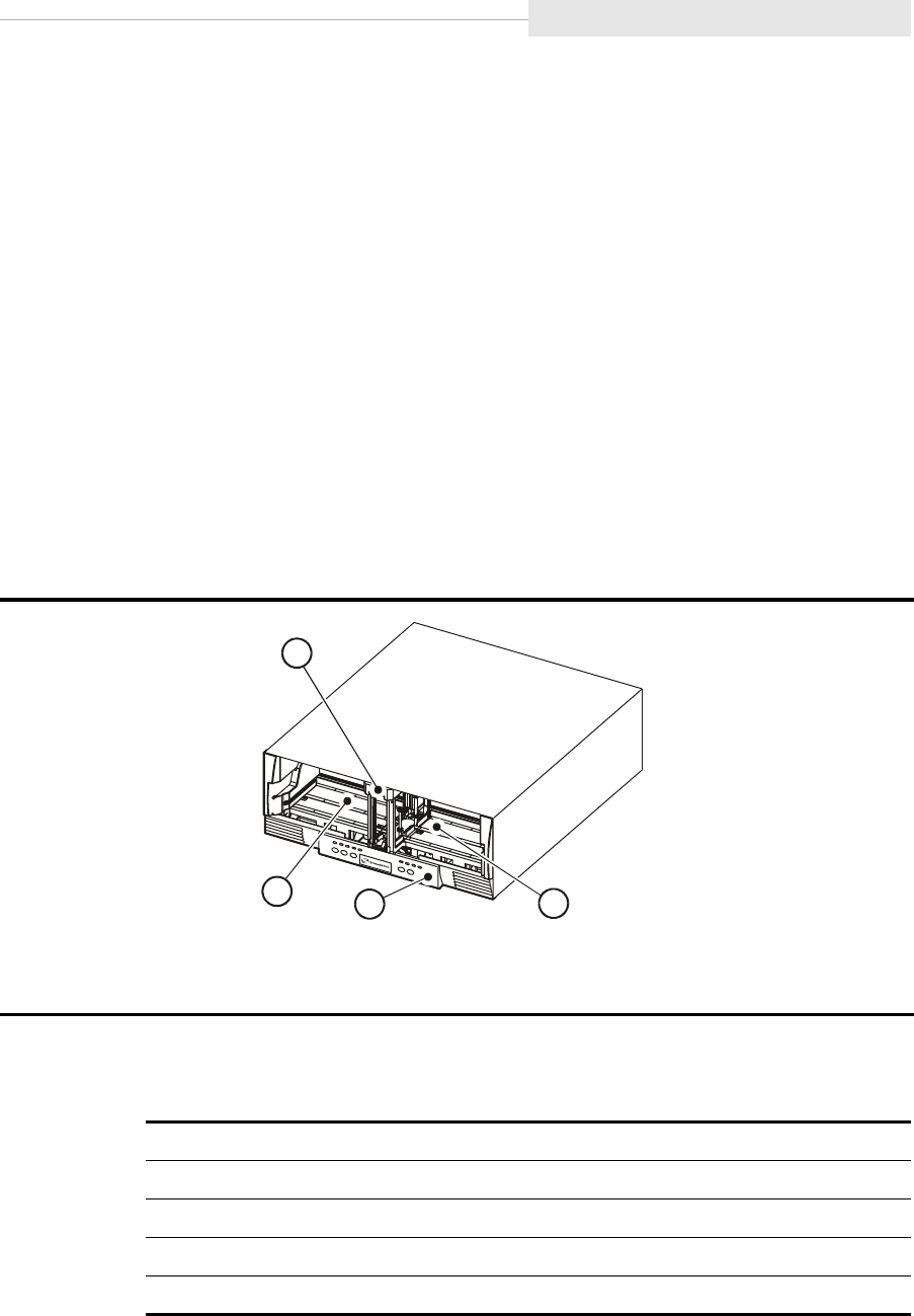
95741 Sixth Edition 5-5
Desktop CSL
■Desktop CSL
Refer to Figure 5-4 for the desktop CSL. This desktop unit has the feed channel,
input bin, output bin, and operator panel identified. The desktop uses Fibre
Channel and SCSI interfaces.
The desktop CSL is stackable up to a height of two units. Protective feet are
installed on the bottom of the unit to allow for stability.
CAUTION:
Equipment damage: The desktop CSL weighs 50 lb and must not be
stacked any higher than two units.
Personal injury: Due to the weight of the CSL, two persons are
recommended to lift or move the CSL.
Note: The desktop has a power switch on the rear to control all enclosed
electronics.
Refer to Table 5-2 for the desktop dimensions.
Figure 5-4. CSL Desktop Unit
1. Feed Channel
2. Input Bin
3. Operator Panel
4. Output Bin
Table 5-2. CSL Desktop Dimensions
Dimension Fibre Channel SCSI
Width 19 in. 19 in.
Depth 30 in. 30 in.
Height 7.625 in. 7.625 in.
Weight 50 lb 50 lb
C53814
1
2
3
4
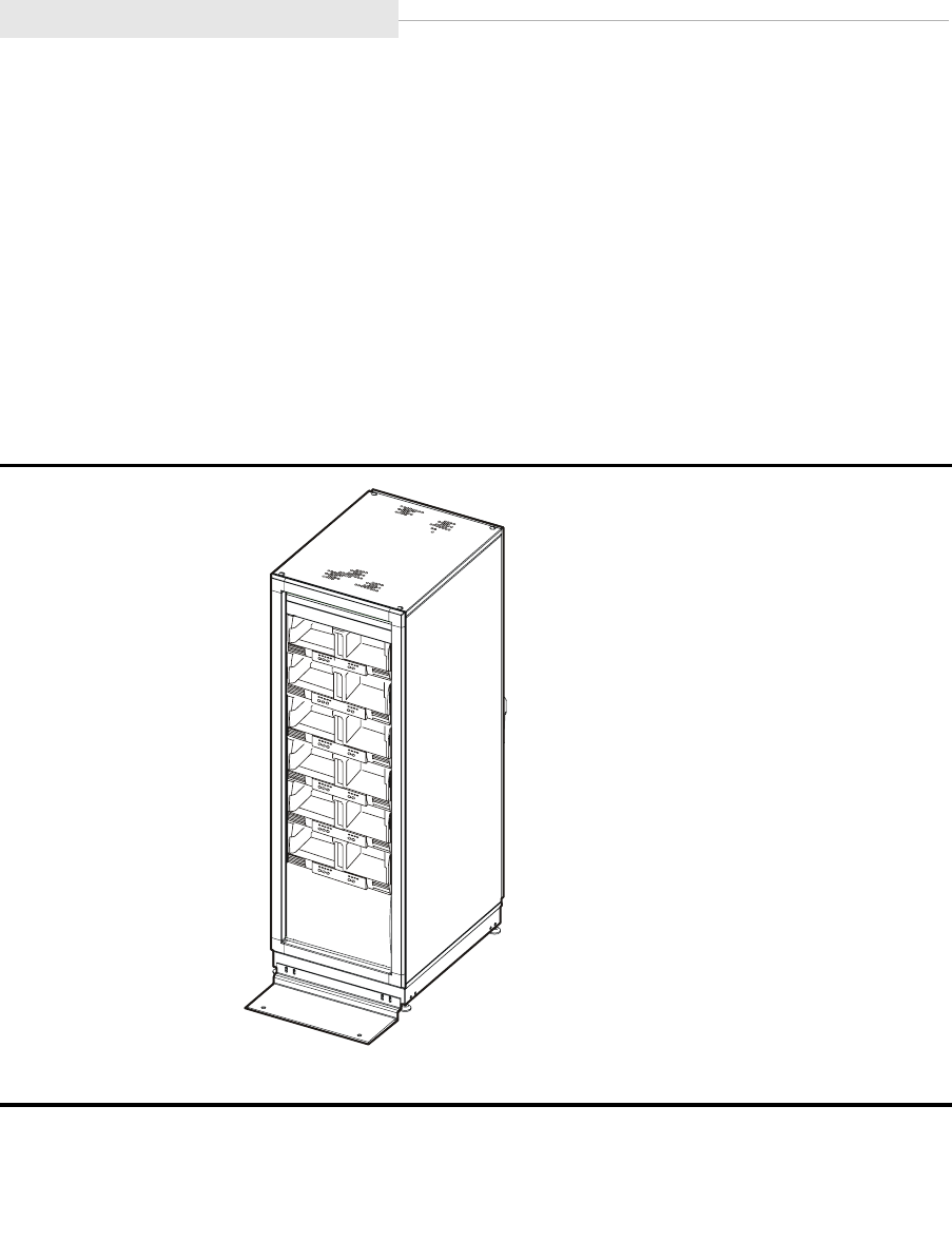
Rack
5-6 Sixth Edition 95741
■Rack
The StorageTek RACK001 may be used to install the rack mount CSL trays. Refer
to Figure 5-5 for the StorageTek RACK001. This rack contains six CSLs. The rack
may contain a combination of 9840 Tape Drives and CSLs.
Note: A customer may wish to use other racks to install the rack mount CSL
trays. This is permissible.
The rack can have up to six CSLs with one per tray, up to 12 manual drives with
two per tray, or a combination of CSLs and manual drives to fill the six slots.
Different trays may have different interfaces.
The rack and CSLs ship in separate containers. The CSLs must be installed
within the rack by a qualified individual.
CAUTION:
Personal injury: Due to the weight of the CSL, two persons are
recommended to lift or move the CSL.
Figure 5-5. RACK001 for CSL Trays
1. StorageTek RACK001
C53659
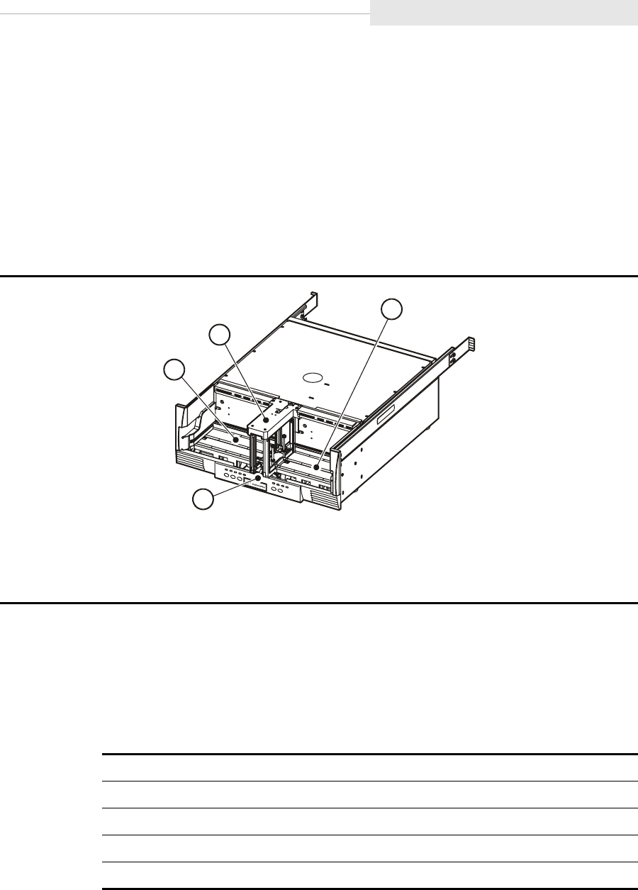
95741 Sixth Edition 5-7
Rack-mount CSL Tray
■Rack-mount CSL Tray
Refer to Figure 5-6 for the rack mount CSL. The rack mount CSL ships with
either a Fibre Channel or SCSI interface.
Note: The slide rails are installed on the CSL in Figure 5-6.
This rack unit has the feed channel, input bin, output bin, and operator panel
identified. The rack unit has a power switch on the rear to control all enclosed
electronics.
CAUTION:
Personal injury: Due to the weight of the CSL, two persons are
recommended to lift or move the CSL.
Table 5-3 provides the rack mount CSL tray dimensions.
Figure 5-6. Rack Mount CSL
1. Input Bin
2. Operator Panel
3. Output Bin
4. Feed Channel
Table 5-3. Rack Mount CSL Tray Dimensions
Dimension Fibre Channel SCSI
Width ANSI/EIA 19-inch rack ANSI/EIA 19-inch rack
Depth 30 in. 30 in.
Height 7.625 in. 7.625 in.
Weight 39 lb 39 lb
C53657
1
3
4
2
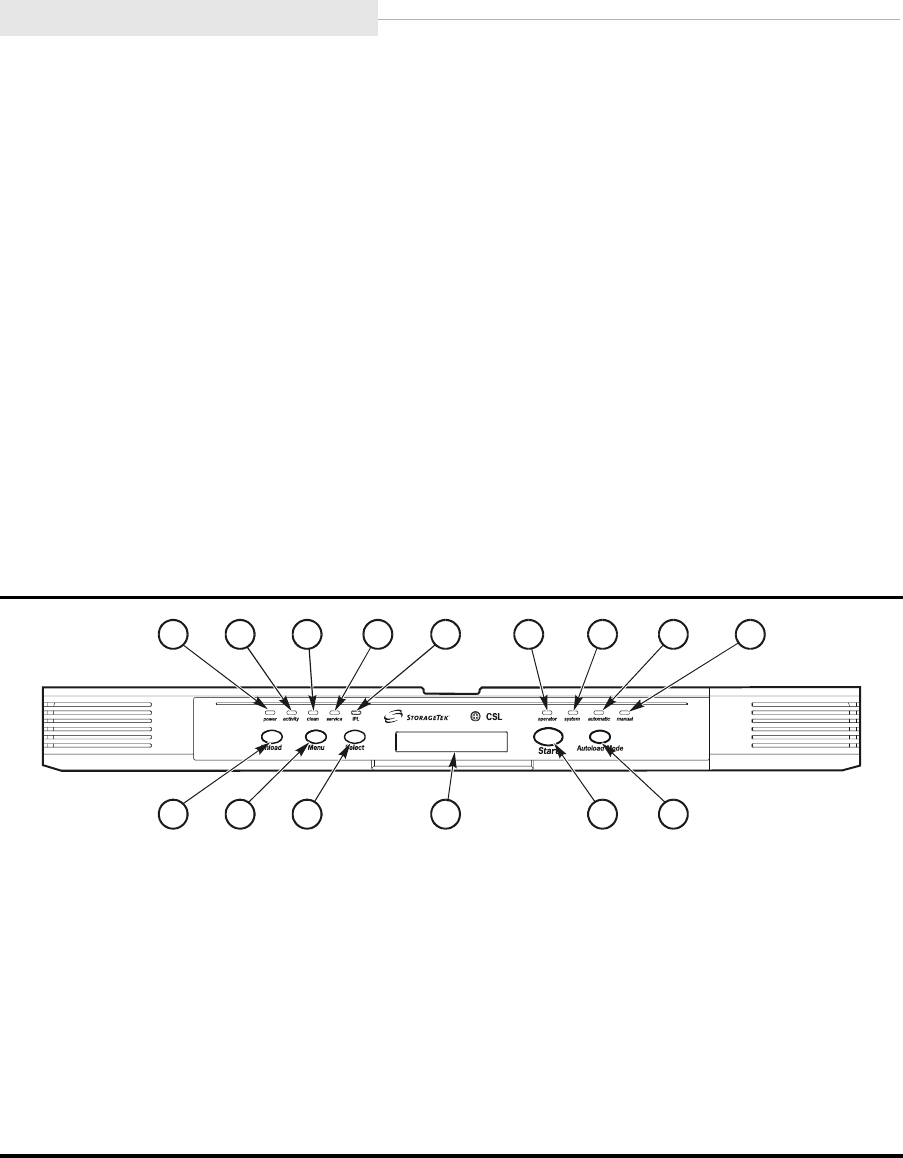
Operator Panel
5-8 Sixth Edition 95741
■Operator Panel
Note: The 9840 Tape Drive and CSL operator panel use small push-button
switches. The term switch or switches is used to identify them
throughout this manual.
The operator panel (Figure 5-7) allows a human interface to the subsystem. The
left half of the operator panel contains the indicators and switches specifically
for the 9840 Tape Drive.
The right half of the operator panel contains the indicators and switches
specifically for the CSL. They are:
•operator Indicator (6)
•system Indicator (7)
•automatic Indicator (8)
•manual Indicator (9)
•Start Switch (14)
•Autoload Mode Switch (15)
Note: Only the CSL indicators and switches are discussed in this section. Refer
to “Operator Panels” on page 1-7 for explanation of the 9840 Tape Drive
indicators and switches.
Figure 5-7. CSL Operator Panel
1. power indicator
2. activity indicator
3. clean indicator
4. service indicator
5. IPL switch
6. operator indicator
7. system indicator
8. automatic indicator
9. manual indicator
10. Unload switch
11. Menu switch
12. Select switch
13. Operator display
14. Start switch
15. Autoload Mode switch
Note: The IPL switch (5) only IPLs the drive. Use the Power switch on the back of the CSL to
IPL the CSL.
C53660
123 45 6
7
8
9
10 11 12 13 14 15

95741 Sixth Edition 5-9
Operator Panel
CSL Switches
Refer to Table 5-4 for CSL operator panel switch descriptions.
Note: Refer to “Operator Panels” on page 1-7 for explanation of the 9840 Tape
Drive switches.
Table 5-4. CSL Operator Panel Switches
Switch Description
Start Switch
(CSL only)
Pressing this switch restarts CSL operation after the operator empties a
full output bin or replenishes an empty input bin.
Also used to restart CSL operation after clearing a misfed cartridge.
Notes:
1. Remove the cartridge before pressing the Start switch.
2. Press the Start switch twice when there is a load failure or
solid operator indicator (red) on the CSL. Pressing the switch
twice re initializes the CSL.
Autoload Mode
Switch
(CSL only)
Pressing this switch changes the operation of the CSL to one of three
modes: System, Automatic, or Manual.
Notes:
1. Select the mode of operation by using the Autoload Mode
switch.
2. Press the Start switch to set the mode of operation.
The CSL powers on in the default mode selected in the drive
configuration menu. The default mode is overridden when the switch is
used to select a new setting. The CSL remains in the selected mode
while the drive is powered on. This does not change the IPL default
mode in the drive configuration menu.
•System allows host to control CSL.
•Auto allows CSL to operate automatically.
•Manual allows manual operations only.
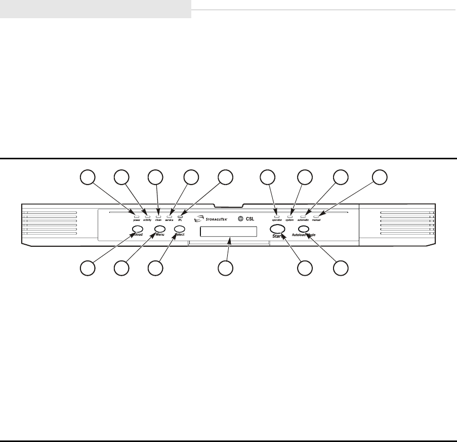
Operator Panel
5-10 Sixth Edition 95741
CSL Indicators
The CSL operator panel indicators (Figure 5-8) are described in Table 5-5 on
page 5-11.
Note: Refer to “Operator Panels” on page 1-7 for explanation of the 9840 Tape
Drive indicators.
Figure 5-8. CSL Operator Panel Indicators
1. power indicator
2. activity indicator
3. clean indicator
4. service indicator
5. IPL switch
6. operator indicator
7. system indicator
8. automatic indicator
9. manual indicator
10. Unload switch
11. Menu switch
12. Select switch
13. Operator display
14. Start switch
15. Autoload Mode switch
Note: The IPL switch (5) only initiates an IPL of the drive. Use the Power switch on the back
of the CSL to IPL the CSL.
C53660
123 45 6
7
8
9
10 11 12 13 14 15

95741 Sixth Edition 5-11
Operator Panel
Table 5-5. CSL Operator Panel Indicators
Indicator Figure 5-8
Number Description Explanation
operator
(red)
(CSL only)
6 When flashing:
When flashing
and xxxx is
displayed:
When constantly
on:
The CSL detected an operator-intervention
condition. Do the following as required:
•See if input bin empty
•Verify if a mode change is in progress
•Remove cartridge(s) from output bin
•Load cartridge(s)
It asks for the specific tape indicated in the
display
It indicates an error condition. To correct, fix
jam (remove cartridge in feed channel) and
press Start switch.
Refer to “Jammed Cartridge” on page 5-30.
system
(green)
(CSL only)
7 Indicates CSL is in System mode: allows host to control CSL.
automatic
(green)
(CSL only)
8 Indicates CSL is in Auto mode: allows CSL to operate
automatically.
manual
(green)
(CSL only)
9 Indicates CSL is in Manual mode: allows manual operations only.
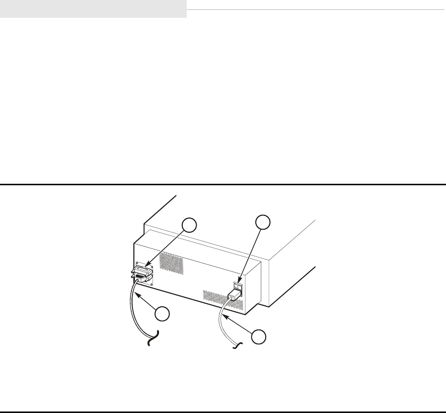
Power On/Off CSL
5-12 Sixth Edition 95741
■Power On/Off CSL
This section provides a process to power on/off the CSL. Figure 5-9 provides
locations of the Power switch, power cord, terminator, and cable for a CSL SCSI
interface.
Note: The CSL Power switch and power cord are located on the rear of the
CSL. The switch and cord are in the same locations on a SCSI or Fibre
Channel CSL.
Power On
1. Ensure the power cord is attached to the receptacle on the rear of the CSL.
Note: The power cord and applicable interface cable (SCSI) should have been
attached during initial installation.
2. If the power cord is not attached to the CSL, do the following:
a. Attach the female end of the power cord to the CSL receptacle.
b. Attach the male end of the power cord to a power outlet.
3. Press the Power switch on the rear of the CSL to ON (1).
4. Verify that the CSL powers on.
Note: A steady asterisk on the operator panel indicates a successful IPL
completion, the drive is online, but not loaded with a cartridge.
Figure 5-9. CSL Power
1. Power switch
2. Power cord
3. SCSI cable
4. Terminator
C5366
1
41
2
3
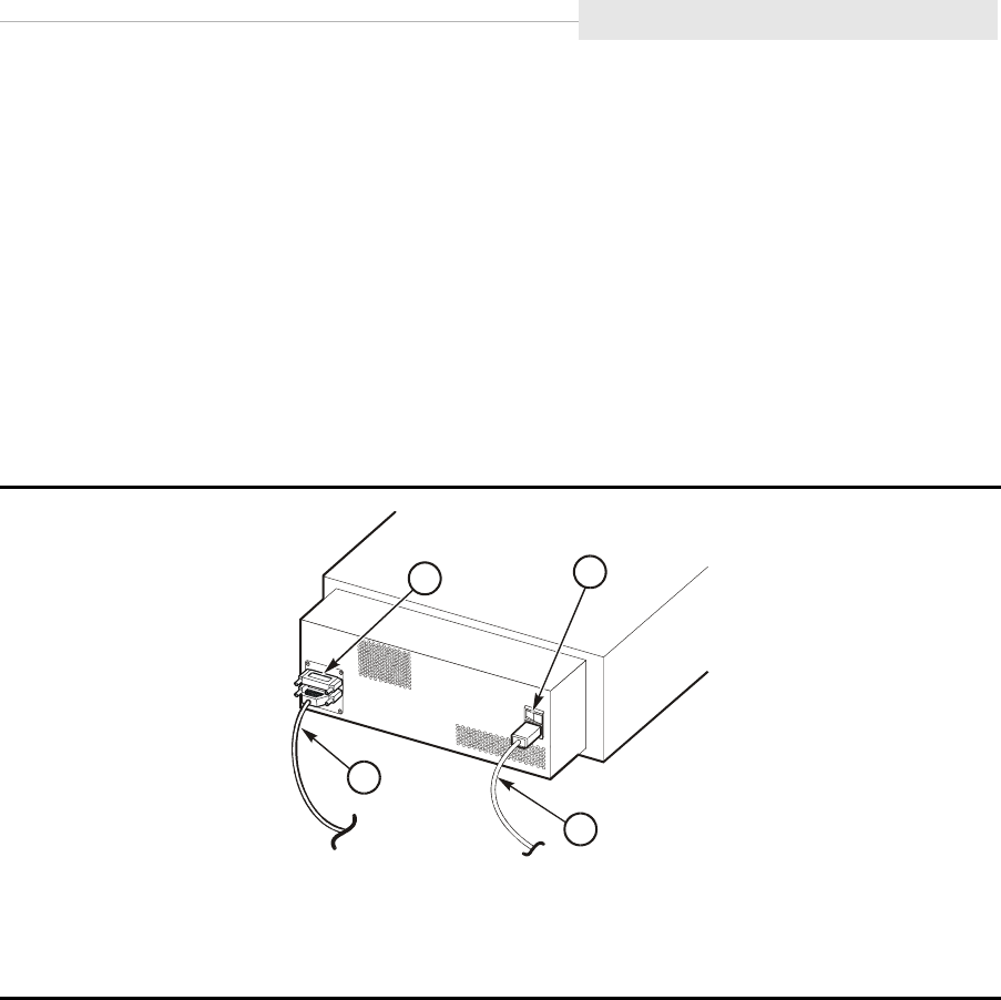
95741 Sixth Edition 5-13
Power On/Off CSL
Power Off
1. Press the Unload switch to eject the cartridge from the CSL.
2. Ask the operator to ensure that the drive has no I/O from the host.
3. Use the operator panel to place the CSL offline.
Note: Refer to Chapter 6, “Menu System.” for instructions to place the CSL
offline.
4. Press the Power switch on the rear of the CSL to OFF (0). This will power off
the CSL.
5. Verify that the CSL powers off.
Note: All indicators are off and the operator panel is blank.
Figure 5-10. CSL Power Switch
1. Power switch
2. Power cord
3. SCSI cable
4. Terminator
C5366
1
41
2
3
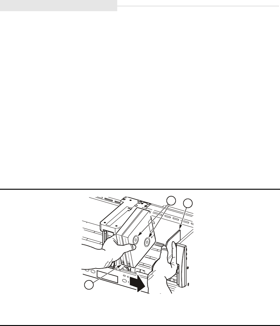
CSL Cartridge Loading/Unloading
5-14 Sixth Edition 95741
■CSL Cartridge Loading/Unloading
This section contains procedures to load and unload cartridges within the CSL.
Cartridge Loading
Note: Engineering recommends no drive activity during cartridge loading. This
ensures that no drive errors are induced.
To correctly load a cartridge into the input bin, follow these instructions and
refer to Figure 5-11.
•Load cartridges into the CSL vertically with the Media Id label (R)
right side up and facing out towards the operator (reels to the right).
•Never load cartridges with the cartridge reels to the left.
•Never load cartridges flat within the CSL. This causes an instant CSL
failure.
1. Move the CSL spring-loaded bookend to the right and hold it in this position
while loading cartridges.
2. Load cartridges into the CSL vertically with the Media Id label (R) facing out
towards the operator (reels to the right).
3. Verify that the customer label (if used) is on the left side of the cartridge
(toward the feed channel).
4. Tilt the cartridge back slightly.
Figure 5-11. Cartridge Loading
1. Cartridge reels
2. Input bin bookend
3. Media ID label (R)
C5365
8
12
3
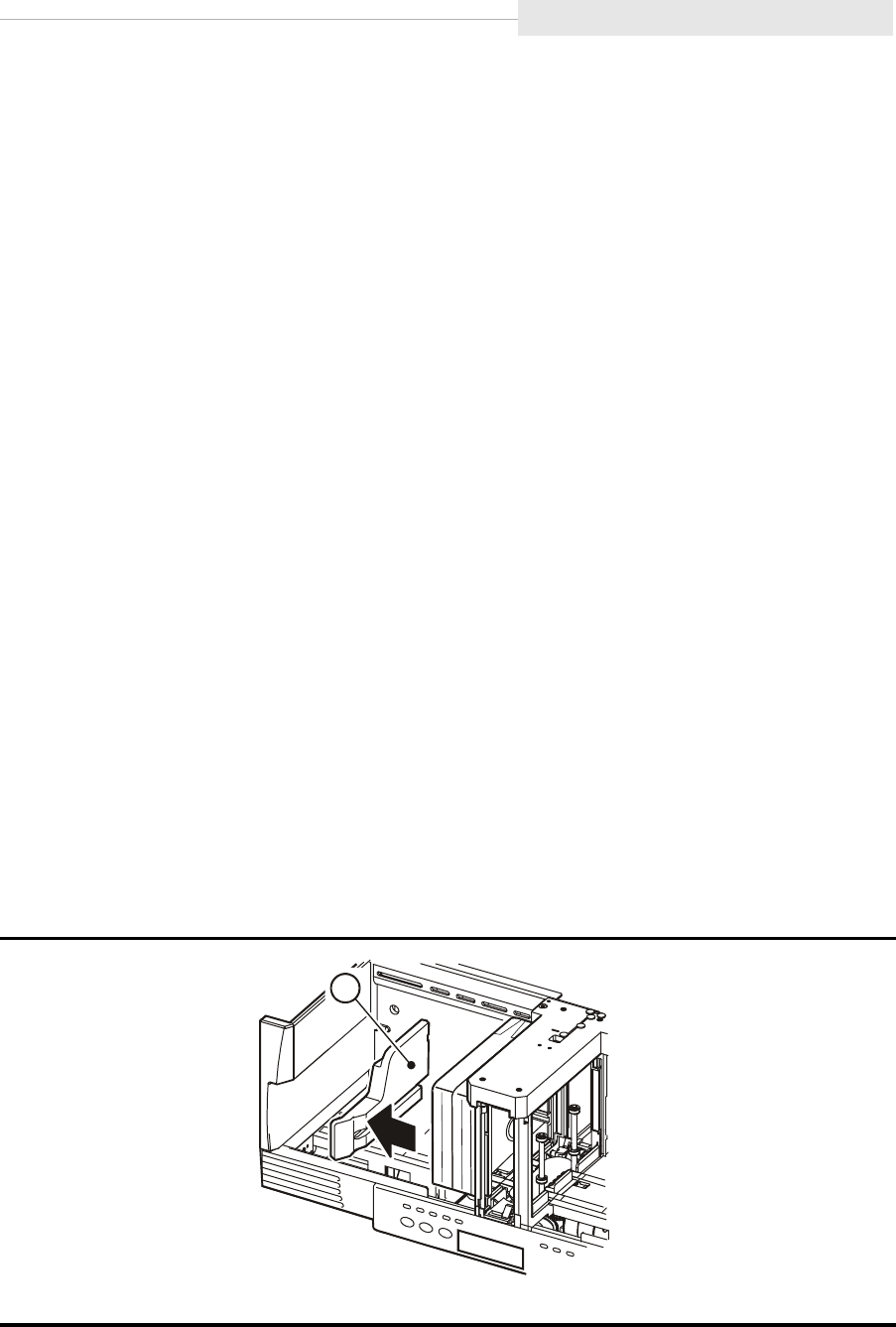
95741 Sixth Edition 5-15
CSL Cartridge Loading/Unloading
5. Insert the bottom-back edge of the cartridge into the CSL input bin.
6. Slide the front edge of the cartridge into the CSL.
7. Slowly release the CSL spring-loaded bookend and ensure it touches the
loaded cartridges.
8. Check that all loaded cartridges are seated correctly.
Note: Ensure that cartridges are aligned vertically and horizontally within
the input bin and that the spring-loaded bookend is pressed firmly
against the cartridges.
Cartridge Unloading
Cartridges are ejected from the feed channel into the output bin (Figure 5-12).
One to seven cartridges may be ejected into the CSL output bin.
Note: When unloading cartridges from the CSL output bin, ensure the spring-
loaded bookend does not slam into the feed channel.
To correctly unload a cartridge from the output bin, follow these instructions
and refer to Figure 5-12:
1. Move the CSL spring-loaded bookend to the left and hold it in this position
while unloading cartridges.
2. Grasp the cartridge(s) and tilt the cartridge back slightly.
3. Remove the cartridge(s).
4. Slowly allow the CSL spring-loaded bookend to touch the feed channel.
Note: Allowing the output or input bin bookend to slam into the feed
channel may cause drive errors.
Figure 5-12. Cartridge Unloading
1. Output bin bookend
C53662
1
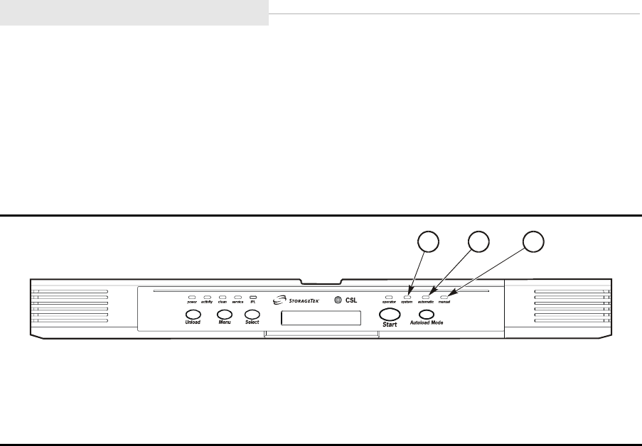
Modes of Operation
5-16 Sixth Edition 95741
■Modes of Operation
The CSL has three distinct modes of operation (Figure 5-13). They are:
•System Mode
•Automatic Mode
•Manual Mode
When power is applied to the CSL, illumination of one of the mode LEDs
indicates the CSL is receiving power and is ready for operation. The operator
indicator may also light, indicating a required manual intervention.
System Mode
The system mode allows the host (enterprise only) to control the CSL. The CSL
stays in the system mode until changed from the operator panel or until the
drive sends a mode change command. The drive changes the mode of
operation at IPL to the mode set in the configuration on the operator panel.
Note: If the input bin is empty while the CSL is in System mode, the input
bin must be replenished, and the Start switch must be pressed to
restart the CSL operation.
If a Load Display command has been sent to the CSL from the
host, a cartridge will be loaded.
If a Load Display command has not been sent to the CSL from
the host, a cartridge will not load until a Load Display command
is received from the host to mount a cartridge.
Figure 5-13. CSL Modes of Operation
1. system indicator
2. automatic indicator
3. manual indicator
C53663
1
2
3

95741 Sixth Edition 5-17
Modes of Operation
Mount Message
When the CSL receives a mount message from the host, one of the following
occurs:
•If the drive is empty and the feed channel contains a cartridge which hasn’t
been previously loaded, the cartridge loads into the drive.
•If the drive and the feed channel are empty, but at least one cartridge is
available in the input bin, then the cartridge loads into the drive.
•Refer to “Priority Mount Mode” on page 5-20 to physically mount a priority
cartridge directly into the CSL.
Unload Message
When the CSL receives an unload message, the cartridge in the drive moves to
the feed channel. The CSL sequences as follows:
•If the output bin is not full, the cartridge is placed into the output bin.
•If the output bin is full, the cartridge remains in the feed channel, and the
operator indicator blinks until the cartridge is removed and the Start switch
is pressed.
Note: Refer to “Cartridge Removal from Feed Channel” on page 5-22 to
remove a priority mounted cartridge from the feed channel.
•If a mount has been pre-queued then, if possible, the next cartridge is
mounted with only one cartridge shift operation.
Place CSL in System Mode
1. Press the Autoload Mode switch until the system indicator illuminates.
2. Press the Start switch to set the System mode.
3. Load up to seven cartridges in the input bin.
4. Press the Start switch.
Note: The CSL does not respond to the Start switch if a cartridge is not in
the input bin of the loader.
5. Unload the output bin when necessary.

Modes of Operation
5-18 Sixth Edition 95741
Automatic Mode
The automatic mode allows the CSL to operate without operator intervention.
Cartridges automatically loads from the input bin into the drive. Cartridges are
loaded in the order they were inserted and unloaded into the output bin when
the operating system is finished with the tape.
Note: If the input bin is empty while the CSL is in Automatic mode, the
input bin must be replenished, and the Start switch must be pressed
to restart the CSL operation.
Refer to “Priority Mount Mode” on page 5-20 to physically mount a
priority cartridge directly into the CSL.
Unload Message
Upon receiving an unload message from the host, the CSL acts identically to the
unload in the system mode with a subsequent pre-queued mount of the next
cartridge into the drive automatically if possible. The CSL sequences as follows:
•If the output bin is not full, the cartridge is placed into the output bin.
•If the output bin is full, the cartridge remains in the feed channel, and the
operator indicator blinks until the cartridge is removed from the output bin
and the Start switch is pressed.
Note: Refer to “Cartridge Removal from Feed Channel” on page 5-22 to
remove a priority mounted cartridge from the feed channel.
•If a mount has been pre-queued then, if possible, the next cartridge is
mounted with only one cartridge shift operation.
Example
A job requires a specific order of cartridges to execute.
1. Load the cartridge tapes into the input bin in the order they will be used.
2. Press the Start switch.
Note: The CSL automatically inserts cartridges into the feed channel in the
order they were inserted in the input bin and ejects them into the
output bin when the operating system has finished with each tape.
Place CSL in Automatic Mode
1. Press the Autoload Mode switch until the green automatic indicator
illuminates.
2. Press the Start switch to set the Automatic mode.
3. Load up to seven cartridges in the input bin in the required sequence (left
to right, in the order they will be used).

95741 Sixth Edition 5-19
Modes of Operation
4. Press the Start switch.
5. Unload the output bin when the job is complete or as necessary.
Manual Mode
In manual mode, the operator has complete control over CSL and drive
operation. While the CSL is in manual mode:
•You may wait for a cartridge mount request and then mount a cartridge.
•You may receive requests for multiple cartridge mounts and load the
requested volumes into the input tray.
•You may remove individual cartridges as they are ejected from the feed
channel or wait until the output bin is full before removing them.
Note: In Manual mode, however, you must press the Start switch each time to
load a cartridge into the drive.
Refer to “Priority Mount Mode” on page 5-20 to physically mount a
priority cartridge directly into the CSL.
Unload
Upon receiving an unload command from the drive, the CSL acts identically to
the unload in the system mode.
After the unload is successfully completed the CSL pauses until the Start switch
is pressed. Pressing the Start switch loads the next available cartridge. The CSL
sequences as follows:
•If the output bin is not full, the cartridge is placed into the output bin.
•If the output bin is full, the cartridge remains in the feed channel, and the
operator indicator blinks until the cartridge is removed from the output bin
and the Start switch is pressed.
Note: Refer to “Cartridge Removal from Feed Channel” on page 5-22 to
remove a priority mounted cartridge from the feed channel.
•If a mount has been pre-queued then, if possible, the next cartridge is
mounted with only one cartridge shift operation.
Place CSL in Manual Mode
1. Press the Autoload Mode switch until the green manual indicator illuminates.
2. Press the Start switch to set the Manual mode.
3. When a mount message appears on the operator panel or system console,
place the requested volumes in the input bin.
4. Press the Start switch.
5. Unload the output bin when necessary.
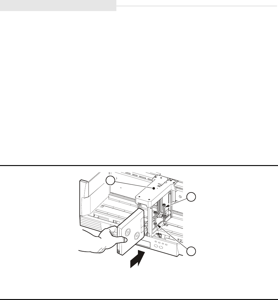
Modes of Operation
5-20 Sixth Edition 95741
Priority Mount Mode
The CSL is a sequential scratch loader. An operator can physically mount a
priority cartridge directly into the unit. The host may issue a Load Display
command with required volser. This command may be issued during any CSL
mode of operation informing the operator to place the cartridge into the feed
channel (Figure 5-14).
Note: The output bin holds only seven cartridges. If you are going to load a
priority cartridge into the feed channel, ensure the output bin is
unloaded or has space for the priority mounted cartridge.
To mount a priority cartridge, review:
•“CSL in System Mode”
•“CSL in Automatic Mode” on page 5-21
•“CSL in Manual Mode” on page 5-22
CSL in System Mode
When the CSL is in the system mode and the drive is not loaded, follow these
procedures to load a priority cartridge:
1. Verify that the drive is currently unloaded and the index rods are on the
right (Figure 5-14).
2. Insert the priority cartridge into the CSL feed channel (Figure 5-14):
a. Insert the cartridge past the cartridge stop mechanism. See Figure 5-15.
b. Do not insert the cartridge past the first index rod (Figure 5-15).
Figure 5-14. Priority Mounting a Cartridge
1. First index rod
2. Second index rod
3. Feed channel
C53664
3
2
1
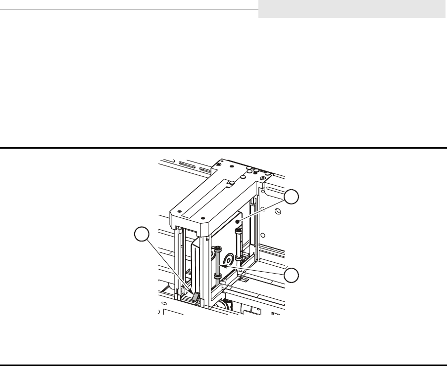
95741 Sixth Edition 5-21
Modes of Operation
Note: If the cartridge is not inserted into the CSL feed channel properly
(Figure 5-15), the CSL cannot insert the cartridge into the drive slot.
3. Check to ensure the operator indicator is flashing.
4. Press the Start switch to feed the cartridge into the drive and to clear the
flashing operator indicator.
CSL in Automatic Mode
The automatic mode is used for sequential mounting of cartridges from the
input bin into the drive. When the CSL is in the automatic mode and the drive is
not loaded, follow these procedures to load a priority cartridge:
1. If there are no cartridges in the input bin, the operator indicator flashes to
signal you to insert a priority (single) cartridge into the feed channel. Press
the Start switch to resume CSL operation.
2. If the input bin is not empty, the mode must be changed to manual mode to
mount the priority cartridge. This prevents the next cartridge from being
automatically loaded.
Note: Refer to Figure 5-15 to correctly load a cartridge into the feed channel
Figure 5-15. Priority Mount Cartridge
1. Cartridge
2. First index rod
3. Cartridge stop mechanism
C5366
5
3
1
2
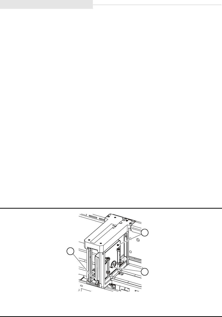
Modes of Operation
5-22 Sixth Edition 95741
.
CSL in Manual Mode
This mode is used for sequential mounting of cartridges from the input bin into
the drive. The operator controls each mount by pressing the Start switch before
each mount. When the CSL is in the manual mode and the drive is not loaded,
follow these procedures to load a priority cartridge:
1. If there are no cartridges in the input bin, the operator indicator flashes
signaling you to put a cartridge into the feed channel.
2. Press the Start switch to resume CSL operation.
Note: Refer to Figure 5-15 on page 5-21 to correctly load a cartridge into the
feed channel.
Cartridge Removal from Feed Channel
If the output bin is full (seven cartridges), and you load an eighth cartridge into
the feed channel for a priority mount, the cartridge cannot eject into the output
bin. The cartridge ejects into the feed channel (Figure 5-16). You must
physically remove the cartridge from the feed channel.
Follow these instructions to remove the eighth cartridge from the feed channel:
1. Remove all cartridges from the input and output bins.
2. Push the cartridge stop mechanism down (Figure 5-16).
3. Grasp the cartridge and remove it from the feed channel.
Figure 5-16. Cartridge Stop Mechanism
1. Cartridge
2. First index rod
3. Cartridge stop mechanism
C5366
5
3
1
2
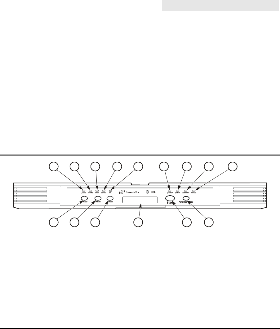
95741 Sixth Edition 5-23
Error and Recovery
■Error and Recovery
Note: Refer to Chapter 7, “Error and Recovery,” for specific drive errors.
Errors may be encountered anytime during operation of the CSL. CSL errors,
recovery, and FSCs are discussed in this section.
Note: The 4EXX FSCs are for the CSL only.
Operator Indicator
When the operator indicator (call out 6) is flashing (Figure 5-17), the CSL
detected an operator-intervention condition. Refer to Table 5-5 on page 5-11 for
a description of the operator indicator.
When the operator indicator is on constantly, the CSL has detected an error
condition (usually a jammed, incorrectly loaded, or tipped cartridge).
•Refer to “Jammed Cartridge” on page 5-30 for the procedure to remove a
jammed cartridge.
•Refer to “Drive Failure to Load” on page 5-24 to unload an incorrectly
loaded cartridge.
•If cartridges are tipped in the input bin and will not load, reposition the
cartridges to clear the malfunction.
Figure 5-17. CSL Operator Panel
1. power indicator
2. activity indicator
3. clean indicator
4. service indicator
5. IPL switch
6. operator indicator
7. system indicator
8. automatic indicator
9. manual indicator
10. Unload switch
11. Menu switch
12. Select switch
13. Operator display
14. Start switch
15. Autoload Mode switch
Note: The IPL switch (5) initiates IPL of the drive only. Use the Power switch on the back of
the CSL to initiate IPL of the CSL.
C53660
123 45 6
7
8
9
10 11 12 13 14 15
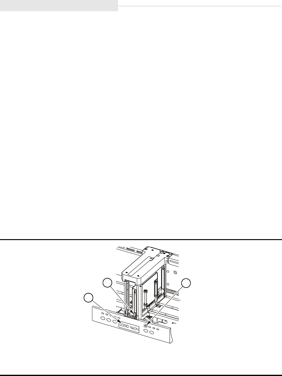
Error and Recovery
5-24 Sixth Edition 95741
Drive Failure to Load
Cartridges may be loaded into the CSL incorrectly (priority mount or from the
input bin). Sometimes, cartridges are loaded with the cartridge reels to the left
(Figure 5-18). When this is done, the CSL attempts to load the cartridge into the
drive. This type of a load causes an instant CSL failure.
CAUTION:
Never load cartridges with the cartridges reels to the left. Only load
cartridges with the cartridges reels to the right.
Incorrect Load Process
This is the process of events when cartridges are loaded incorrectly into the
CSL. The cartridge reels are facing to the left (Figure 5-18). You cannot see them
in Figure 5-18.
1. The CSL attempts to load the cartridge into the drive.
2. The CSL loads the cartridge approximately three-quarters of the way into
the drive.
3. The drive senses the cartridge is loaded incorrectly.
4. The CSL moves the cartridge out of the drive and to the cartridge stop
mechanism (Figure 5-18).
5. Fault Symptom Code (FSC) LOAD 4E04 displays on the operator panel and
the operator indicator is on constantly.
Figure 5-18. Ejected Cartridge (Failure to Load)
1. operator indicator
2. Display
3. Cartridge stop mechanism
C53666
1
3
2

95741 Sixth Edition 5-25
Error and Recovery
Recovery Process
1. Remove the incorrectly loaded cartridge:
a. Press down on the cartridge stop mechanism (Figure 5-18 on
page 5-24).
b. Grasp the cartridge and pull it from the feed channel.
2. Clear the CSL error.
a. Press the Start switch (Figure 5-17 on page 5-23) to clear the solid
operator indicator.
b. After the Start switch is pressed, the operator indicator blinks and the
operator display still shows LOAD 4E04 until a successful load or you
press the Unload switch (Figure 5-18 on page 5-24) to clear the display.
3. Ensure all remaining cartridges to be loaded are placed within the input bin
correctly (cartridge reels to the right).
4. The CSL is now ready for normal operations.
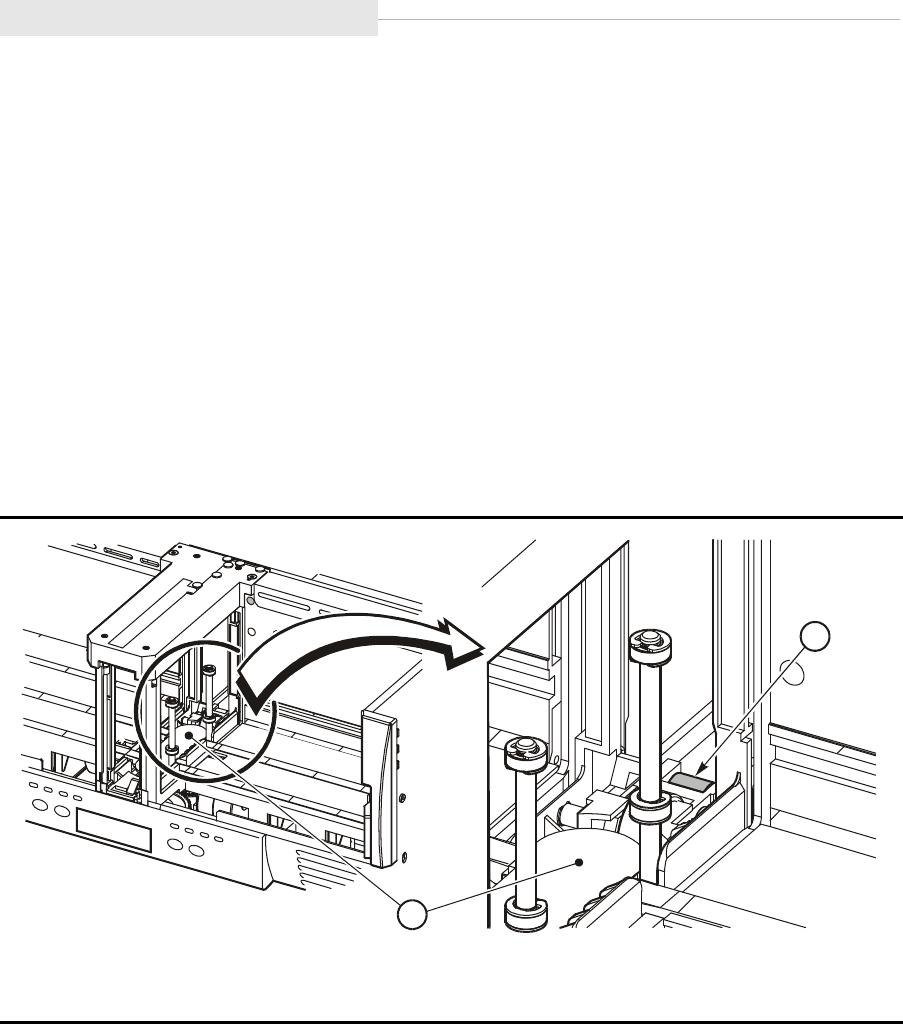
Error and Recovery
5-26 Sixth Edition 95741
Failure to Unload Cartridge
Cartridges may fail to unload from the drive. When this malfunction occurs, the
drive or CSL may be the defective FRU. The defective FRU is dependent on how
far the cartridge is ejected from the drive and its relationship to the feed roller
(Figure 5-19).
•If the cartridge fails to unload and does not eject on the feed roller
(Figure 5-19 on page 5-26), the drive is the defective FRU.
•If the cartridge fails to unload and does eject on the feed roller (Figure 5-19
on page 5-26), the CSL is most likely the defective FRU.
Note: Defective FRU Probability is: 90% CSL, 10% drive.
Have a qualified technician remove and replace the drive or CSL.
Figure 5-19. Feed Roller
1. Feed channel area
2. Feed roller
C53824
2
1
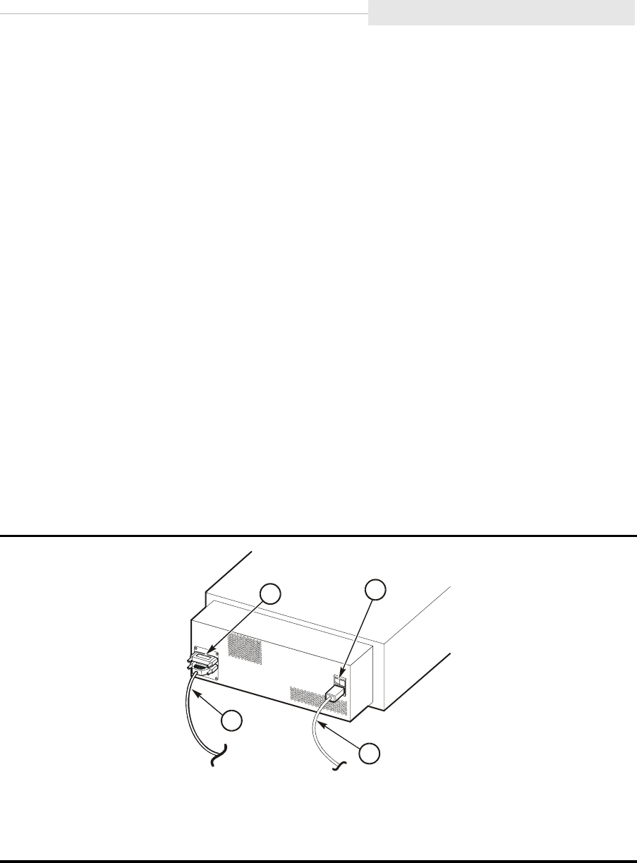
95741 Sixth Edition 5-27
Error and Recovery
Clearing CSL Errors
Refer to the following process to clear CSL errors. Follow the directions
explicitly.
Note: Any time the operator indicator is flashing or on solid, clear the obvious
error. Refer to Table 5-5 on page 5-11 for a description of the operator
indicator.
1. After correcting the error, press the Start switch (Figure 5-17 on page 5-23,
call out 14) to clear the operator indicator.
2. If pressing the Start switch did not clear the indicator, press the Start switch
twice.
Note: Press the Start switch twice when there is a load failure or solid
operator indicator (red) on the CSL. Pressing the switch twice re
initializes the CSL.
3. If pressing the Start switch twice did not clear the operator indicator, power
cycle the CSL to bring it back online. Refer to “Power On/Off CSL” on
page 5-12 to correctly power cycle the CSL. Figure 5-20 on page 5-27 shows
the location of the power switch.
4. If power cycling the CSL did not clear the operator indicator, the CSL must
be replaced by a qualified technician.
Figure 5-20. CSL Rear View
1. Power switch
2. Power cord
3. SCSI cable
4. Terminator
C5366
1
41
2
3

Error and Recovery
5-28 Sixth Edition 95741
Fault Symptom Codes
Perform the following sequence of checks if a CSL error occurs.
1. Check the CSL operator indicator to see if it is flashing (operator summoned)
or on solid (failure). Clear the obvious error.
2. If the CSL does not indicate any problems, check the FSC list (Table 5-6).
3. Check sense data at the host for any FSC in addition to the information
provided in Table 5-6.
Note: Some malfunctions are caused by communications errors between the
CSL and the drive, and also by internal software. If the malfunctions
continue, force a dump of the drive for engineering evaluation.
Table 5-6 provides the 4EXX FSCs, suspected malfunction, and possible fix.
Table 5-6. CSL FSCs
FSC Malfunction Fix
4E04 Cartridge installed incorrectly (180
degrees out, cartridge reels to left).
Drive replaced within the CSL, and
4E04 displays when cartridge is
loaded.
Insert cartridge correctly.
Install cartridge with reels to
the right. See “Recovery
Process” on page 5-25.
Drive may not be aligned
correctly within CSL. Have a
qualified technician remove,
replace, and align the drive.
4E05 SCSI load command rejected due to
no CSL being attached to the drive.
Check the black control cable
between the drive and CSL.
Final action: have a qualified
technician replace the drive.
4E0C SCSI load command cannot be
performed. The CSL is not in the
System mode.
Select the System mode.
4E0D SCSI load command cannot be
performed. There is no cartridge in
the input bin or feed channel.
Load cartridge.
Note: The 4E0D FSC may occur after a cleaning cartridge has been
unloaded.
4E11 ESCON load command is rejected
due to no CSL being attached to the
drive.
Have a qualified technician
check the black control cable
between the drive and CSL.
Final action: have a qualified
technician replace the drive.

95741 Sixth Edition 5-29
Error and Recovery
4E23 CSL encountered an error during an
unload.
1. Check the CSL for any error
condition.
2. Remove the cartridge.
3. Press the Start switch once.
Note: LOAD 4E23 will
display until you press
the Load or Start
switch.
4E2D SCSI load command failed due to
the CSL no longer in the System
mode. The mode was changed
during the load.
Return CSL to System Mode.
4E31 SCSI load command failed due to
the CSL no longer in the System
mode. The mode was changed
during the load. This error occurs
immediately after a cleaning or
dump cartridge has just been
unloaded.
Return CSL to System Mode.
4E34 SCSI load command failed due to
no cartridge being available to load.
This error only occurs immediately
after a cleaning or dump cartridge
has just been unloaded and the CSL
is in the Automatic mode.
Load a cartridge.
Table 5-6. CSL FSCs
FSC Malfunction Fix

Jammed Cartridge
5-30 Sixth Edition 95741
■Jammed Cartridge
A jammed cartridge in a CSL is not a common malfunction. A jammed cartridge
unloads from the drive and remains on the feed roller (Figure 5-21). It does not
eject fully into the feed channel.
You must know how to remove jammed cartridges when the malfunction
occurs. Follow the procedures in this section to remove a jammed cartridge.
See Figure 5-21 for the CSL manual unload device (MUD) screw location. The
MUD screw is located to the right of the feed channel.
Notes:
•Only use the MUD mechanism to remove jammed cartridges
(cartridges still in the 9840 Tape Drive) or to reset the drive for
shipping (cartridges not on the feed roller).
•The MUD screw must be turned clockwise (CW) to remove jammed
cartridges.
•The MUD screw must be turned counterclockwise (CCW) to reset
the drive to its shipping position and to install and lock the shipping
insert into the drive.
.
Figure 5-21. 9840 Tape Drive Manual Unload Device
1. MUD screw
2. Input bin
3. Feed channel
C5366
7
1
3
2
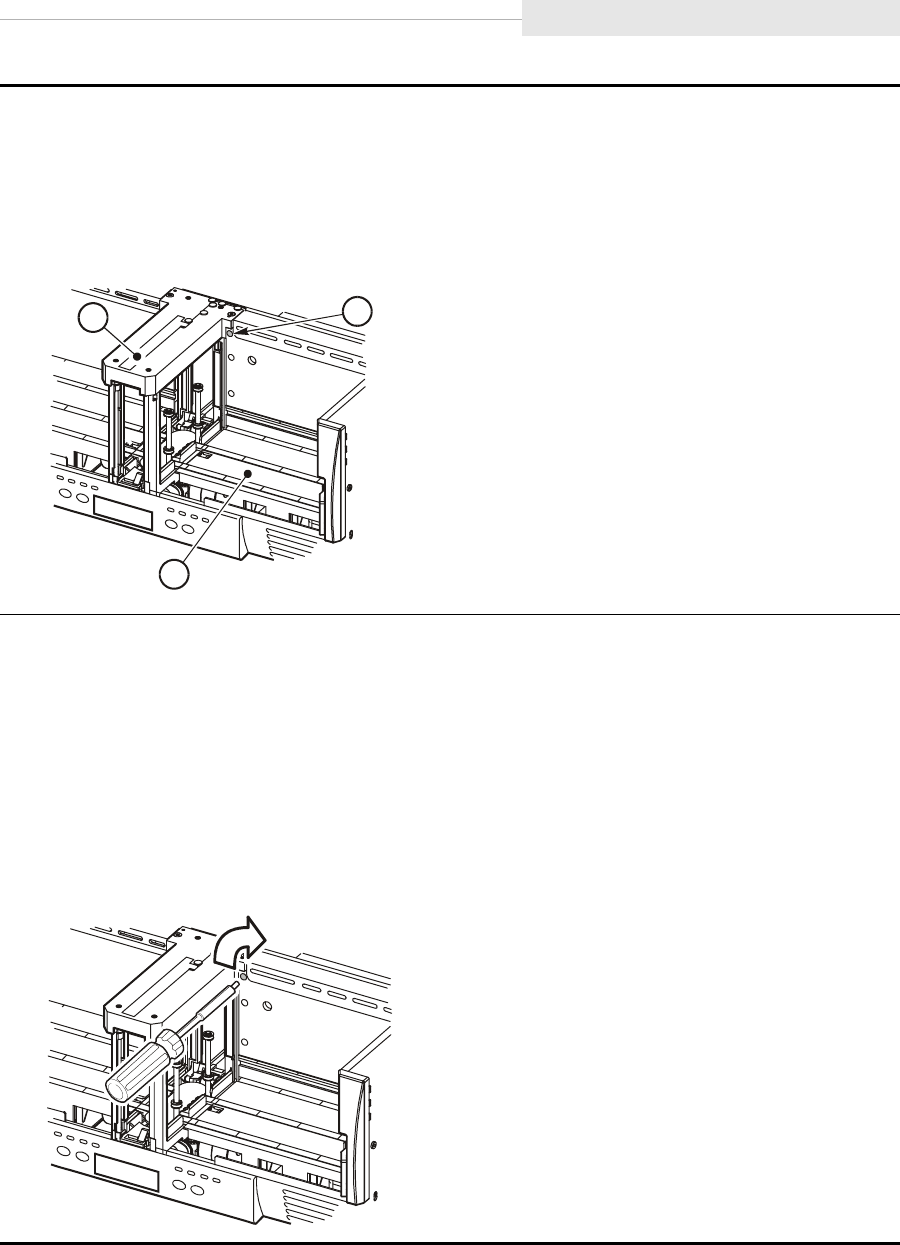
95741 Sixth Edition 5-31
Jammed Cartridge
1. Power off the CSL if power is applied (“Power On/Off CSL” on page 5-12).
2. Remove all cartridges from the input and output bins.
3. Locate the MUD screw within the CSL input bin (upper-left area).
Note: The CSL MUD screw is located to the right of the feed channel.
1. Mud screw
2. Input bin
3. Feed channel
4. Obtain a long-common 1/8 in. screwdriver and insert it into the MUD slot.
5. Press against the spring-loaded MUD screw until it stops.
Note: Do not turn the screwdriver CCW when removing a jammed cartridge.
6. Slowly turn the screwdriver CW to remove the jammed cartridge (may take
approximately ten turns).
a. Turn the MUD screw until it will not turn any further. This action lowers the reel
motors within the drive.
C5366
7
1
3
2
C5366
8
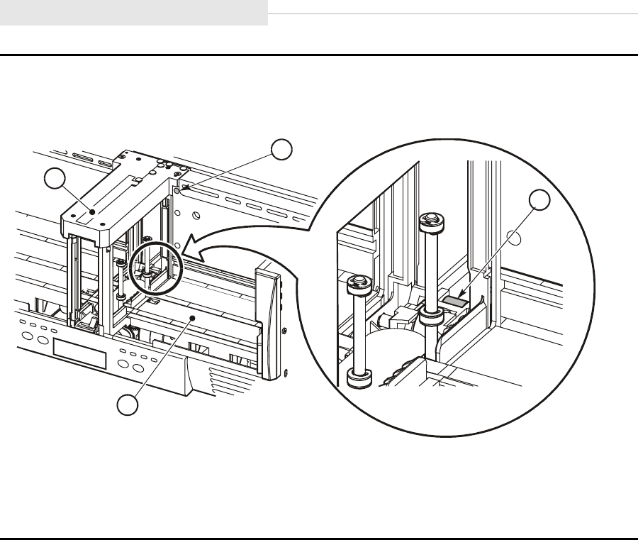
Jammed Cartridge
5-32 Sixth Edition 95741
b. Turn the MUD screw CW until the cartridge rests on the feed roller.
Note: Feed roller is callout number 2 in figure below.
1. MUD screw
2. Feed roller (DETAIL A)
3. Input bin
4. Feed channel
C53669
2
1
4
3
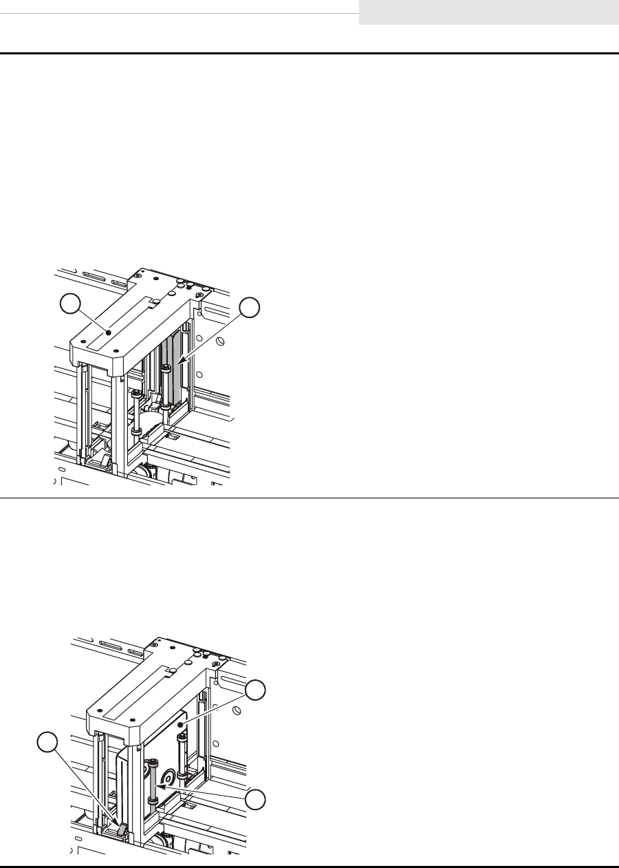
95741 Sixth Edition 5-33
Jammed Cartridge
7. Remove the screwdriver.
8. Remove the cartridge from the 9840 Tape Drive.
Note: The cartridge will not eject completely out of the CSL. It will only eject out of the
drive and stop deep inside the feed channel on the feed roller.
a. Use both hands and reach between the input bin and output bin bookends.
b. Grasp the cartridge with your fingers.
c. Slowly work the cartridge out of the drive through the feed channel.
1. Cartridge
2. Feed channel
9. Work the cartridge through the feed channel to the cartridge stop mechanism.
a. Push down on the cartridge stop mechanism.
Note: This allows the cartridge to be removed from the front of the feed channel.
b. Grasp the cartridge and remove it from the feed channel.
1. Cartridge
2. First index rod
3. Cartridge stop mechanism
C53670
1
2
C5366
5
3
1
2
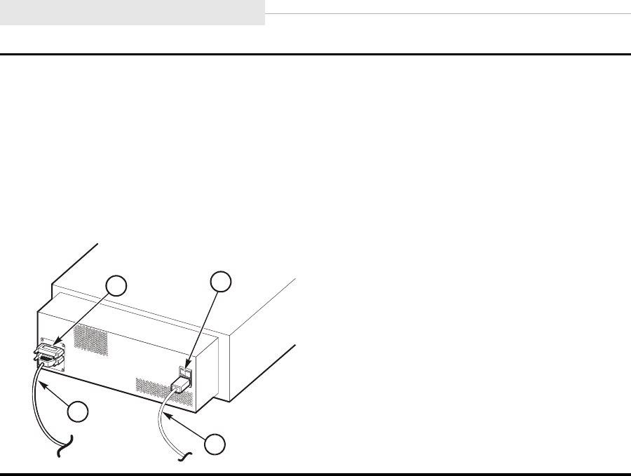
Jammed Cartridge
5-34 Sixth Edition 95741
10. Power on the CSL.
11. Refer to “Power On/Off CSL” on page 5-12 for the power on procedures.
Notes:
•Refer to the figure below for location of the power switch.
•If cartridges continue to jam, the CSL is defective and must be replaced by a qualified
technician.
1. Power switch
2. Power cord
3. SCSI cable
4. Terminator
C5366
1
41
2
3
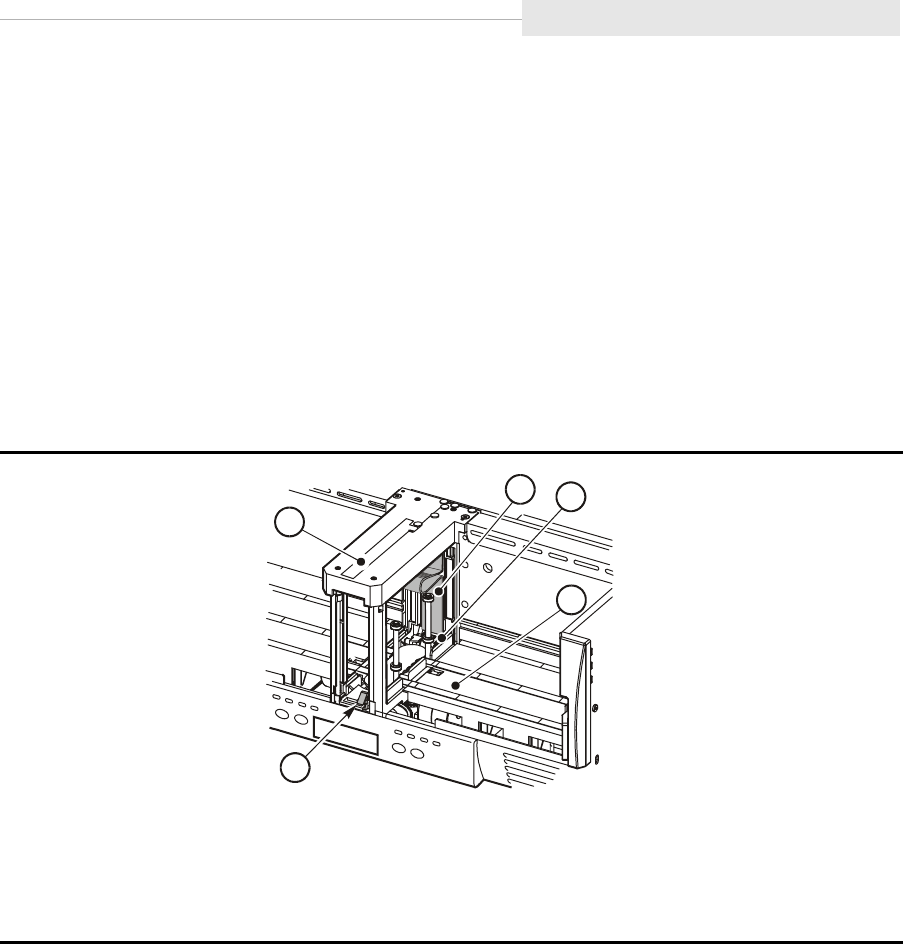
95741 Sixth Edition 5-35
Shipping Insert
■Shipping Insert
This section contains instructions to remove, install, and lock a shipping insert
into the CSL. The shipping insert must always be inserted and locked into the
CSL. Read caution below.
CAUTION:
If the shipping insert is not locked into the tape drive, the drive head will
become damaged in shipment.
When you receive a new CSL, you must remove the shipping insert. Figure 5-22
provides the location of the shipping insert within the CSL feed channel.
Figure 5-22. Shipping Insert
1. Shipping insert
2. Feed roller
3. Input bin
4. Cartridge stop mechanism
5. Feed channel
C5367
1
12
4
3
5
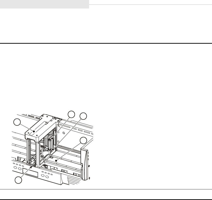
Shipping Insert
5-36 Sixth Edition 95741
Removal
Follow these instructions to remove the shipping insert from the CSL.
1. Locate the shipping insert within the feed channel.
2. Push the input bin bookend to right of the input bin and hold it in place.
3. Reach through the input bin and squeeze the shipping insert handle together.
Note: Squeezing the handle unlocks the shipping insert from the drive.
4. Slide the shipping insert out through the feed channel to the cartridge stop mechanism.
5. Push down on the cartridge stop mechanism and remove the shipping insert.
1. Shipping insert
2. Feed roller
3. Input bin
4. Cartridge stop mechanism
5. Feed channel
6. Store the shipping insert.
C5367
1
12
4
3
5
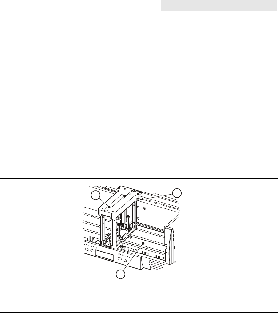
95741 Sixth Edition 5-37
Shipping Insert
Install and Lock
Follow these instructions to properly install and lock the shipping insert into a
CSL. Before you can lock the shipping insert into the CSL, you must use the
MUD screw (Figure 5-23) to raise the reel motors and to lower the cleaning
brush within the drive.
CAUTION:
If the shipping insert is not locked into the tape drive, the drive head will
become damaged in shipment.
Notes:
•Only use the MUD mechanism to reset the drive for shipping.
•The MUD screw must be turned CCW to reset the drive to its
shipping position and to install and lock the shipping insert into the
drive.
Figure 5-23. MUD Screw in CSL
1. MUD screw
2. Input bin
3. Feed channel
C5366
7
1
3
2
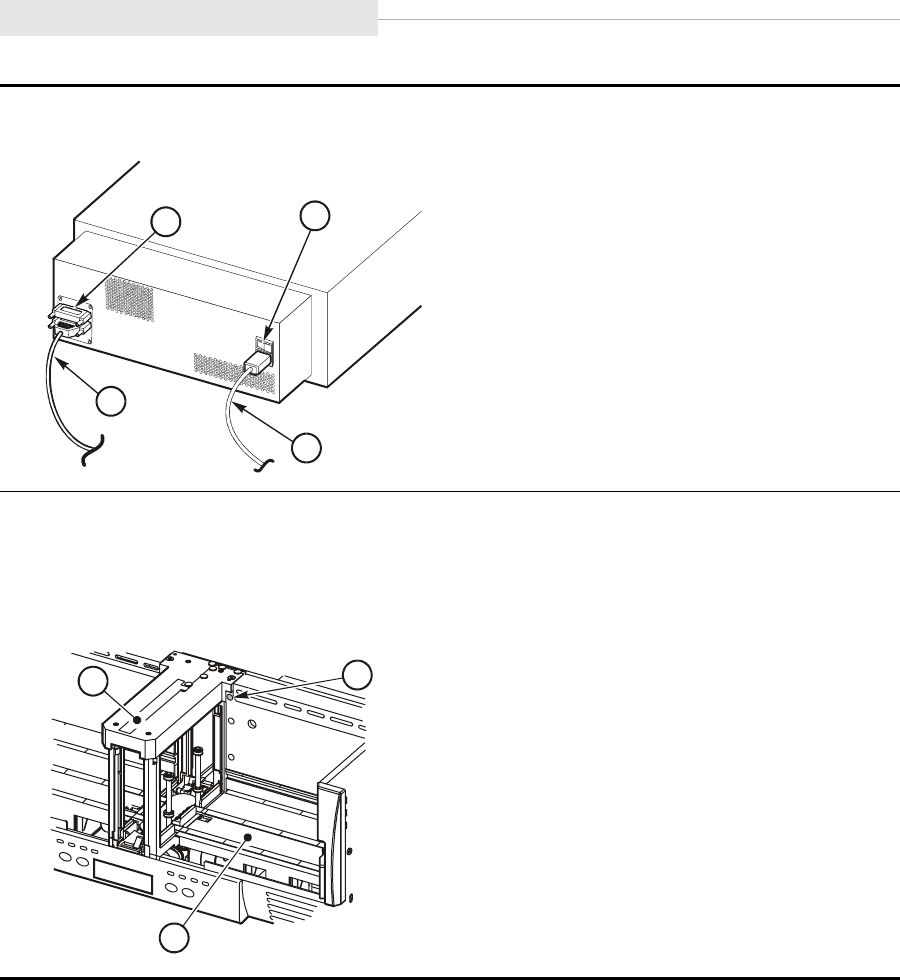
Shipping Insert
5-38 Sixth Edition 95741
1. Power off the CSL if power is applied.
1. Power switch
2. Power cord
3. SCSI cable
4. Terminator
2. Locate the MUD screw to the right side of the feed channel.
3. Obtain a long-common 1/8 in. screwdriver and insert it into the MUD slot.
4. Press against the spring-loaded MUD screw until it stops.
1. MUD screw
2. Input bin
3. Feed channel
C5366
1
41
2
3
C5366
7
1
3
2
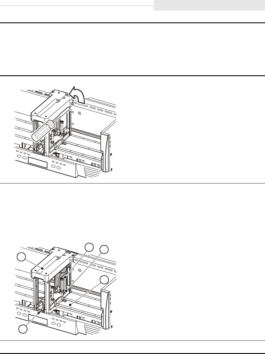
95741 Sixth Edition 5-39
Shipping Insert
Note: Do not turn the screwdriver CW when preparing the drive for a shipping insert.
5. Slowly turn the screwdriver CCW to raise the reel motors and to lower the cleaning
brush.
Note: When the MUD screw will not turn any further, the reel motors are raised and the
cleaning brush is lowered.
6. Remove the screwdriver.
7. Insert and lock the shipping insert in the 9840 Tape Drive.
Note: Some force must be used to insert the shipping insert past the feed roller.
8. Gently pull the shipping insert outward to verify it is locked within the carriage.
1. Shipping insert
2. Feed roller
3. Input bin
4. Cartridge stop mechanism
5. Feed channel
9. Send the defective CSL to StorageTek.
C53672
C5367
1
12
4
3
5

Shipping Insert
5-40 Sixth Edition 95741
This page intentionally left blank.

95741 Sixth Edition 6-1
6
Menu System
This chapter describes the menu system for the 9840 Tape Drive and how to
perform specific operations using the menus and submenus, such as:
•Review drive configuration and firmware release level
•Reconfigure the drive
•Special drive operations
When the drive is online, you can view the current configuration settings and
firmware level. When the drive is offline, you can change the configuration
settings or perform special drive operations.
This chapter contains:
•“Menu Structure Overview” on page 6-3
-“Online Main Menu Operation” on page 6-4
-“Offline Main Menu Operation” on page 6-6
•“Explanation of Menu Trees” on page 6-8
•Menu Trees:
-“Fibre Channel View Configuration Status” on page 6-9
-“Fibre Channel Change Configuration Menu” on page 6-10
-“SCSI View Configuration Status” on page 6-23
-“SCSI Change Configuration Menu” on page 6-24
The single-page menu trees show sequences graphically. You can use them if
you do not need detailed instructions. The multi-page menu tables have more
instructions and detail for less experienced users.
Note: Drives are preset to manufacturing’s default settings. Therefore, all
drives must be reconfigured to specific requirements upon installation.
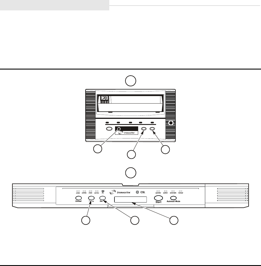
6-2 Sixth Edition 95741
You must use the operator panel Menu switch (1, Figure 6-1), Select switch (2,
Figure 6-1), and display (3, Figure 6-1) to access all menus and submenus. Press
the Menu switch to navigate from one menu item to the next. Press the Select
switch to enter a submenu and navigate through the options in the submenu.
Figure 6-1. Operator Panels
A is the standard operator panel. B is the CSL operator panel.
1. Menu Switch
2. Select Switch
3. Display
C53679
service
A
B
3
12
123
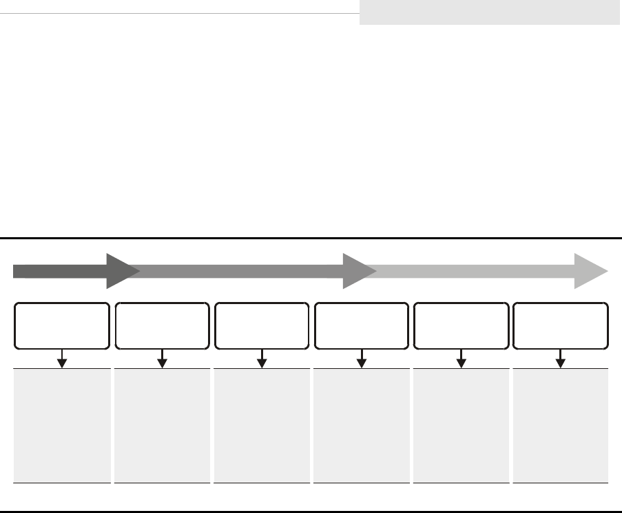
95741 Sixth Edition 6-3
Menu Structure Overview
■Menu Structure Overview
Figure 6-2 shows an overview of the 9840 main menu system.
When the Menu switch on the Operator Panel is pressed, the first main menu
allows selection of Online (default) or Offline main menus. Pressing the Select
switch toggles the option, and pressing the Menu switch advances the display to
the next main menu.
View/Change Configuration main menu views drive configuration settings in
Online, or allows drive configuration changes when Offline. Invoke the
submenus by pressing the Select switch, or advance to the next main menu
item by pressing the Menu switch.
The Drive Firmware Main Menu displays the drive firmware release level. The
CSL Firmware Main Menu displays the CSL firmware release level (when the
drive is installed in a CSL), or CSL NONE (when not installed in a CSL).
The Exit Menu provides two choices:
•Exit the menu system by pressing the Select switch
•Loop back to the Online/Offline Main Menu item by pressing the Menu
switch.
If you exit the menu system with the drive Offline, the Operator Panel will
alternately flash Offline as a reminder that drive status is still Offline. This
reminder will flash until the drive is placed back Online, or powered-off.
Figure 6-2. Main Menu System
C53514
CSL Firmware
No Submenus
Shows CSL
Firmware
Release Level
(None = No CSL)
Drive Firmware
No Submenus
Shows Drive
Firmware
Release Level
Exit Menu
No Submenus
Exits Menu System
Online/Offline
Entry Point to
Other Menus.
View/Change
Configuration
Drive Configuration
Submenus
View - Online
Change - Offline
Drive Operations
Drive Operations
Submenus
(Offline Only)

Menu Operations
6-4 Sixth Edition 95741
■Menu Operations
Menu operations for Online and Offline are very similar. Online menus only
provide viewing of current settings and/or status. Offline menus allow option
selections and/or change to various settings. In both menu systems, press Select
to toggle/increment options, or to answer “Yes”. Press Menu to advance to the
next menu, or to answer “No”.
Online Main Menu Operation
When the drive is Online, the main menus shown on Figure 6-3 on page 6-5
are active. With Online selected, press Menu (one or more times) to advance to
the View Configuration (View CFG ?) Main Menu, where you will have two
choices:
•Press Select (Yes) to view configuration submenus which display the
current drive configuration settings.
•Press Menu (No) to bypass, and advance to the next main menu.
Notes:
1. Fibre Channel interface drives provide for Port A and B Enable/
Disable selection before the View Configuration Main Menu
appears.
2. The View Configuration submenus vary slightly relative to specific
interface type.
The view-only Firmware Release Main Menu displays the drive’s firmware code
release level in the following format: Rx.yy.zzzc; where x = major revision level,
y = minor revision level, z = integration number, and c = channel interface
type (f for Fibre Channel, and s for SCSI).
When a 9840 drive is installed in a CSL, the view-only CSL Firmware Release
Main Menu displays the CSL’s firmware code release level in the following
format: CSL x.y.zz; where x = major revision level, y = minor revision level, and
z = integration number. CSL None is displayed when the drive is not installed
in a CSL.
The Main Exit Menu (Exit Menu?) allows choice of exiting menu system by
pressing Select (Yes); or, looping back to the Online/Offline Main Menu by
pressing Menu (No).
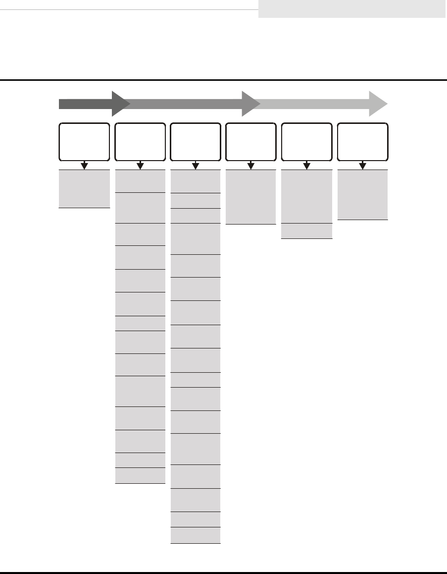
95741 Sixth Edition 6-5
Menu Operations
Figure 6-3 provides an overview of the online menus and submenus.
Figure 6-3. Online Main Menus and Submenus
C53517
View
Configuration
Entry Point
to View
Configuration
Menus
View CSL
Firmware
Level
No
Submenus
View CSL
Firmware
Release Level
(None = No CSL)
Exit
Menu
No
Submenus
Exits Menu
System
View Drive
Configuration
(Fibre Channel)
Compress
Mode
Port A and B
Attributes
Library
Address
Exit or Loop
Data Security
Erase (
Mode DSE)
Tape Bar
Usage
CSL
Power Up
Mode
Language
Selection
VolSafe
Usage
Full Code
Emulation
Mode
View Drive
Firmware
Level
No
Submenus
View Drive
Firmware
Release Level
View Drive
Configuration
(SCSI)
Compress
Mode
SCSI ID
Library
Address
Exit or Loop
DSE Mode
SCSI Target
Negotiation
Mode
SCSI Speed
Mode
Tape Bar
Usage
Emulation
Mode
CSL
Power Up
Mode
SCSI Width
Mode
Language
Selection
VolSafe
Usage
Full Code
World Wide
Name (H)
World Wide
Name (L)
Serial Number
World Wide
Name (H)
World Wide
Name (L)
Serial Number

Menu Operations
6-6 Sixth Edition 95741
Offline Main Menu Operation
When the drive is Offline, the main menus shown on Figure 6-4 on page 6-7
are active. With Offline selected, press Menu (one or more times) to advance to
the Change Configuration (Chng CFG ?) Main Menu, where you will have
two choices:
•Press Select (Yes) to enter change configuration submenus which
display options to change drive configuration settings.
•Press Menu (No) to bypass, and advance to the next main menu.
Note: Fibre Channel interface drives provide for Port A and B Enable/Disable
selection before the Change Configuration Main Menu appears.
The Change Configuration submenus allow you to change drive configuration
settings. Options vary, depending on the type of channel interface in the drive.
The Drive Operations (Drv Menu ?) menu allows you to perform:
•Initial Program Load (IPL) from a tape (loads new firmware code into
the drive EEPROM from a code tape)
•Create a dump tape (format a tape cartridge to receive dump data)
•Create a code tape (copy firmware from drive EEPROM onto a tape)
•Create a data tape (format a tape cartridge to receive data)
•Rebuild Media Information Region (MIR)
•Run diagnostic routines.
Note: See the drive operations menu tree (Figure 6-10 on page 6-34) for
additional information.
Press Select (Yes) to enter submenus, or Menu (No) to bypass, and advance to
the next main menu.
The view-only Firmware Level and CSL Firmware Level Main Menus function
the same as they did for Online Main Menu Operation.
The Main Exit Menu, like it did for Online Main Menu Operation, provides a
choice to exit the menu system or loop-back to the Online/Offline Main Menu.
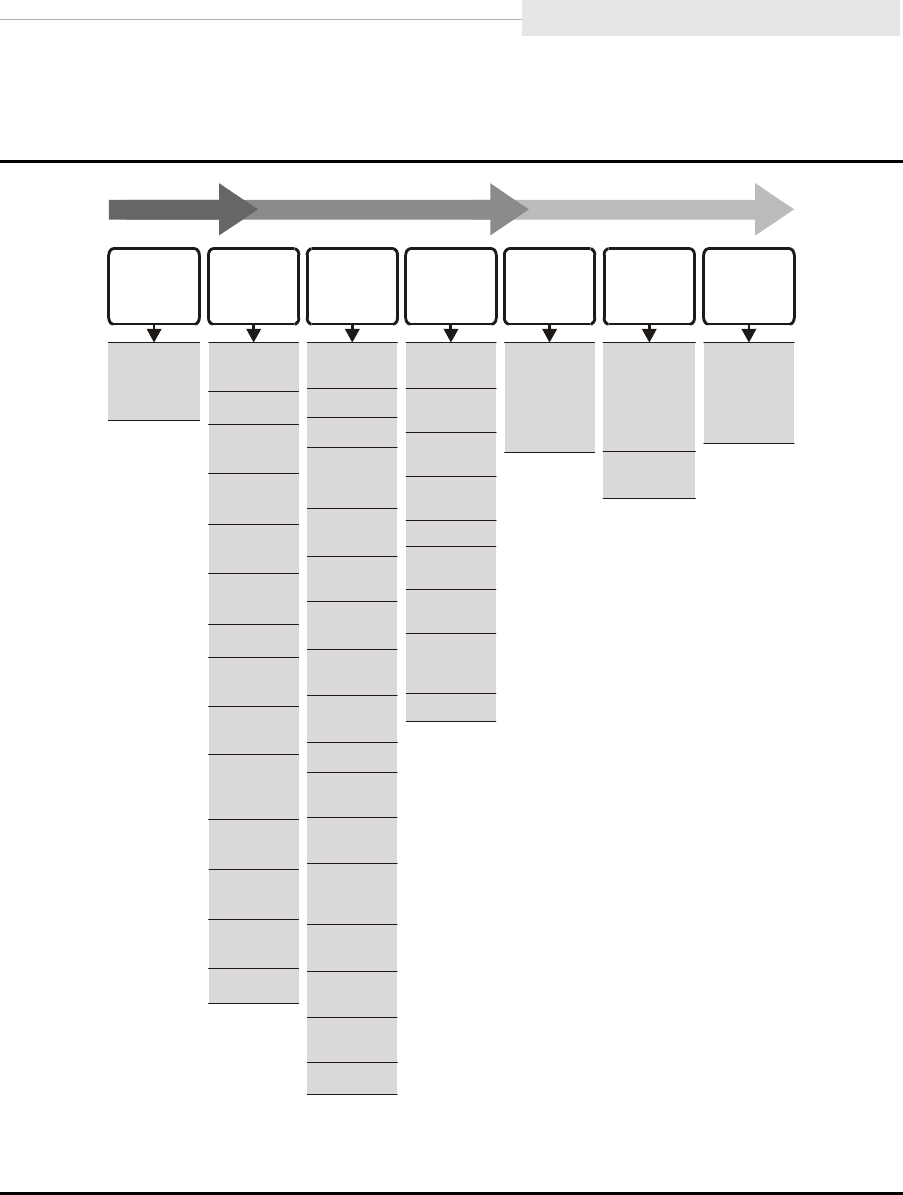
95741 Sixth Edition 6-7
Menu Operations
Figure 6-4 provides an overview of the offline menu operations.
Figure 6-4. Offline Main Menu and Submenus
C53515
Change
Configuration
Entry Point
to Change
Configuration
Menus
View CSL
Firmware
Level
No
Submenus
View CSL
Firmware
Release Level
(None =
No CSL)
Exit Menu
No
Submenus
Exits Menu
System
View Drive
Firmware
Level
No
Submenus
View Drive
Firmware
Release Level
Drive
Operations
IPL from Tape
(Update MC)
Make Dump
Tape
Make Code
Tape
Make Data
Tape
Rebuild MIR
Write/Read
Diagnostic
Servo Head
Diagnostic
Servo Load/
Unload
Diagnostic
Exit or Loop
Change
Drive
Configuration
(Fibre Channel)
Compress
Mode
Port A and B
Attributes
Library
Address
Exit or Loop
DSE Mode
Tape Bar
Usage
CSL
Power Up
Mode
Language
Selection
VolSafe
Usage
Emulation
Mode
Full Code
Save if
Needed
Change
Drive
Configuration
(SCSI)
Compress
Mode
SCSI ID
Library
Address
Exit or Loop
DSE Mode
SCSI Target
Negotiation
Mode
SCSI
Speed Mode
Tape Bar
Usage
Emulation
Mode
CSL
Power Up
Mode
SCSI
Width Mode
Language
Selection
VolSafe
Usage
Full Code
Save if
Needed
World Wide
Name (H)
World Wide
Name (H)
World Wide
Name (L)
World Wide
Name (L)
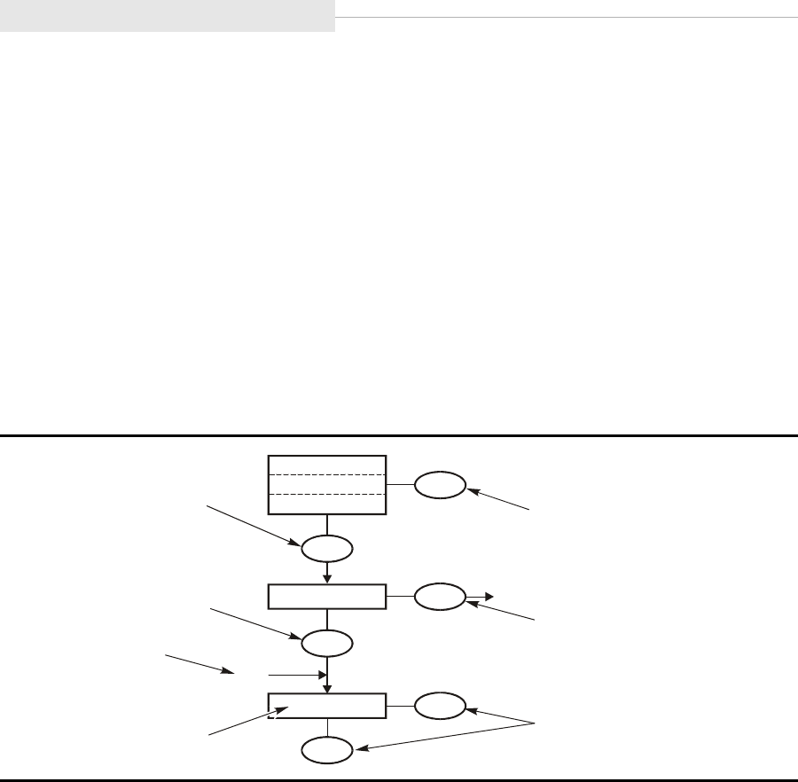
Explanation of Menu Trees
6-8 Sixth Edition 95741
■Explanation of Menu Trees
Figure 6-6 through Figure 6-10, later in this chapter provide graphic operational
sequences for the menu operations:
•Figure 6-6 “Menu Tree—View Fibre Channel Configuration” on page 6-9
•Figure 6-7 “Menu Tree—Change Fibre Channel Configuration” on page 6-10
•Figure 6-8 “Menu Tree—View SCSI Configuration” on page 6-23
•Figure 6-9 “Menu Tree—Change SCSI Configuration” on page 6-24
•Figure 6-10 “Menu Tree—Drive Operations” on page 6-34
Use the legend, shown in Figure 6-5, as an aid to navigate the Menu Trees.
There are only two Operator Panel switches used for the menu system: Menu
and Select. The boxes show menu displays.
Pressing the Menu switch advances the menu display along the flow direction,
sets a menu option after selection, or answers “No” to a menu choice question.
Pressing the Select switch toggles/increments menu options or answers “Yes” to
a menu choice question. When there is not an option, selection, or choice
presented, such as during view-only menus, pressing Select has same result as
pressing Menu.
To enter variable characters or digits, press Select to start the change mode.
(The left-most variable character/digit begins to flash.) Each additional press of
the Select switch increments the value one step. When the desired value is
displayed, press Menu to set the value and advance flash to next variable
character/digit. When the last variable character/digit has been set, Menu
accepts entry and advances display to the next menu, or Select restarts the
change mode.
Figure 6-5. Menu Trees Legend
C53230
Press Select to step options
,
then press Menu to invoke,
and step to next menu.
Select
Option 1
Option 2
Option etc.
Press Select for “Yes”
and go to submenu.
View only display,
press Menu or Select to
step to next menu.
Press “Menu” for “No”
and bypass submenu.
Press “Menu” to bypass.
Connection from
related menu or
submenu.
Characters
in italics are
variable.
xxxyyyzzza
From
No
Yes
Select
Option ?
Select
Menu
Menu
Menu
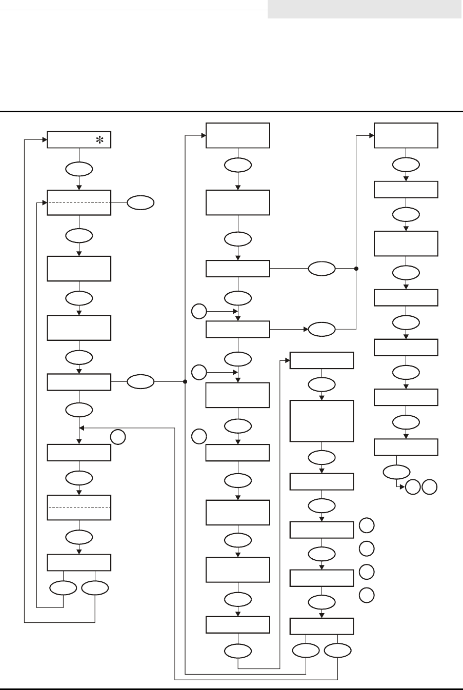
95741 Sixth Edition 6-9
Fibre Channel View Configuration
■Fibre Channel View Configuration Status
Figure 6-6 provides a menu tree for viewing a Fibre Channel configuration.
Figure 6-6. Menu Tree—View Fibre Channel Configuration
C5351
1
Toggle
Port A
(ENA/DIS)
XXX
CSL
( /NONE)
XXXXX
x.y.z
Port B
(ENA/DIS)
XXX
Select
(Select Online)
Online
Offline
No
Select
View CFG ?
Yes
Menu
Select
Rx.yy.zzza
Exit Menu? FullCode
(Y/N)
X
VolSafe
(Y/N)
X
Tape Bar
(Y/N)
X
Full DSE
(Y/N)
X
Cmprss
(Yes/Off/No)
Xxx
Select
View PrtA?
Select
View PrtB?
Menu
Emul XXXXX
No
No
Yes
Yes
(Language)
Menu
Select
S/N=zzzzzz
Exit CFG ?
CSL
(System/Auto
/Manual)
Xxxxxx
Lib Adr xy
Hard PA
(Y/N)
X
Soft PA
(HI/LO)
XX
MaxSz
xxxx
A_I=
xxyyzz
H=
xxxxxxxx
H=
xxxxxxxx
L=
yyyyyyyy
L=
yyyyyyyy
PA=
xx, yyy
No
No
Yes
Yes
Menu
Menu
Menu
Menu
MenuMenu
Menu
Menu Menu
Menu
Menu
Menu
Menu
Menu
Menu
Menu
Menu
Menu
Menu
Menu
Menu
Menu
Menu
Menu
Menu
Menu
Menu
Notes:
1.
2.
3.
4.
Firmware release
level.
Port A steps to view
PrtB?
Port B steps to Tape
Bar Y/N.
Current language
slection desplayed.
1
2
3
4
32
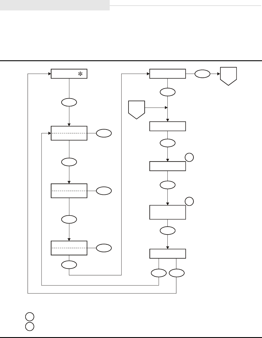
Fibre Channel Change Configuration
6-10 Sixth Edition 95741
■Fibre Channel Change Configuration Menu
Figure 6-7 provides a menu tree for changing a Fibre Channel configuration
Figure 6-7. Menu Tree—Change Fibre Channel Configuration (Sheet 1 of 3)
C53512
Notes:
.
1.
2
Firmware
release number.
CSL
Firmware
release number only
appears when drive is installed in a CSL.
Menu
Toggle
Select
(Select Offline)
Online
Offline
Menu
Port A ENA
Port A DIS
Select
Menu
Port B ENA
Port B DIS
Select
Menu
Menu
Select
Exit Menu?
No Yes
No
Select
Chng CFG ?
Yes
Menu
Sheet 2
A
Sheet 2
E
Rx.yy.zzza
Menu
1
CSL
(x.y.z/NONE)
XXXXX
Menu
2
Drv Menu ?
Menu
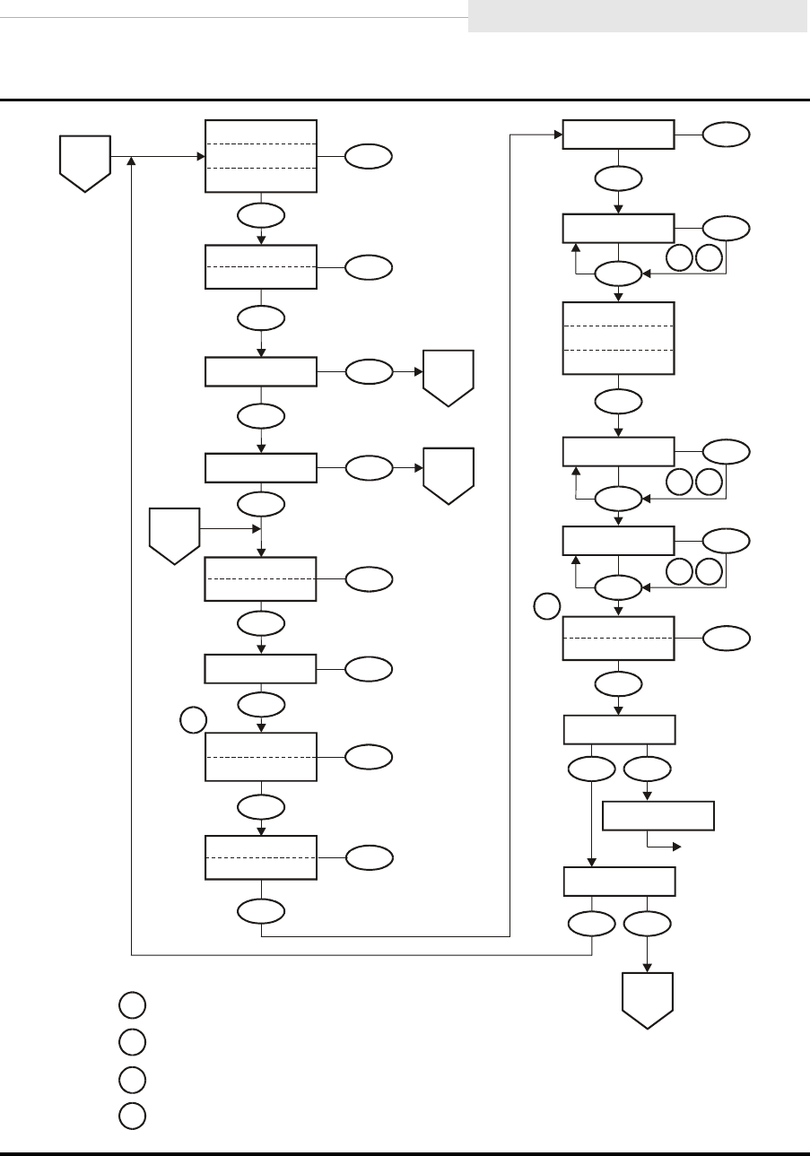
95741 Sixth Edition 6-11
Fibre Channel Change Configuration
Figure 6-7. Menu Tree—Change Fibre Channel Configuration (Sheet 2 of 3)
C53976
Menu
Emul
XXXXX
Select
3
2
3
2
3
2
4
1
Lib Adr xy
Select
Menu
WWN Custom
WWW Normal
Select
Menu
Saving CFG
Save/IPL ?
IPL
Menu
Select
No Yes
Menu
Select
No Yes
Select
Menu
H=xxxxxxxx
Select
Menu
L=yyyyyyyy
FullCode Y
FullCode N
Select
Menu
VolSafe Y
VolSafe N
Select
Menu
Menu
CSL System
CSL Auto
CSL Manual
Full DSE Y
Full DSE N
Select
Menu
Tape Bar Y
Tape Bar N
Select
Menu
Language ?
Select
Menu
Port A
(ENA/DIS)
XXX
Select
Cfg PrtA?
No
Yes
B
Sheet 3
Menu
Sheet 1
E
Cmprss Yes
Cmprss Off
Cmprss No
Select
Menu
Sheet 1
A
Select
Cfg PrtB?
No
Yes
Menu
Sheet 3
D
Sheet 3
C
Notes:
1
2
3
4
Normal
resets
WWN
to
factory
preset.
VolSafe
Y
requires
password
from StorageTek
Technical
Support.
When all digits are steady, press Menu to accept; or press Select
to restart change mode.
Press Select to step flashing digit. Press Menu to set.
Exit CFG ?
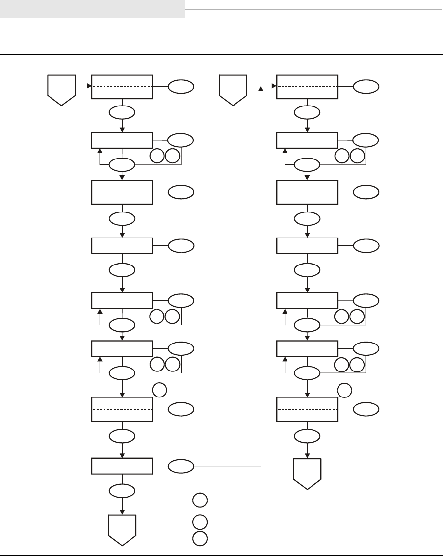
Fibre Channel Change Configuration
6-12 Sixth Edition 95741
Figure 6-7. Menu Tree—Change Fibre Channel Configuration (Sheet 3 of 3)
Notes:
.
3.
Normal resets WWN to factory preset.
1.
2
When all digits are steady, press
Menu to accept; or press Select to
restart change mode.
Press Select to step flashing digit.
Press Menu to set.
C5397
8
P
ort
AP
ort
B
Select
Soft PA HI
Soft PA LO
Menu
Select
MaxSz xxxx
Menu
1 2
1
2
1
2
1
2
1 2
12
Select
Menu
PA=xy, yyy
Select
Menu
H=xxxxxxxx
Select
Menu
L=yyyyyyyy
Select
WWN Custom
WWN Normal
Menu
3
Select
Hard PA Y
Hard PA N
Menu
Sheet 2
B
No
Select
Cfg PrtB
Yes
Menu
Sheet 2
D
Select
Soft PA HI
Soft PA LO
Menu
Select
MaxSz xxxx
Menu
Select
Menu
PA=xy, yyy
Select
Menu
H=xxxxxxxx
Select
Menu
L=yyyyyyyy
Select
WWN Custom
WWN Normal
Menu
3
Select
Hard PA Y
Hard PA N
Menu
Sheet 2
C
Sheet 2
D

95741 Sixth Edition 6-13
Fibre Channel Change Configuration
Table 6-1 provides detailed instructions to change configuration of a Fibre
Channel drive when the drive is offline.
Table 6-1. Menu Table—Fibre Channel Configuration
Options Notes Procedure
Online/Offline Main Menu
Online/
Offline
Defaults to Online at power-on.
Offline must be selected to
change configuration settings.
OffLn Pend may display while
waiting for a system response or
diagnostics completion.
1. If required, press Menu repeatedly
until Online or Offline is
displayed.
2. If Online, press Select to toggle
option to Offline.
3. Press Menu to advance to the Port
A Enable/Disable menu.
Port A Enable/Disable Menu
Port A ENA
Port A DIS
Defaults to enabled (ENA).
Port A enabled. (Normal for
single port configuration.)
Port A disabled (DIS).
DIS Pend or ENA Pend may
display while waiting for a system
response.
1. Press Menu to bypass, or
2. Press Select to toggle option;
then, press Menu to set, and
advance to the Port B Enable/
Disable menu.
Note: Manufacturing ships drive with the Port A ENA option selected.
Port B Enable/Disable Menu
Port B ENA
Port B DIS
Defaults to ENA.
Port B enabled.
Port B disabled. (Normal for
single port configuration.)
DIS Pend or ENA Pend may
display while waiting for a system
response.
1. Press Menu to bypass, or
2. Press Select to toggle option;
then, press Menu to set, and
advance to the Change
Configuration (Chng CFG) Main
Menu.
Note: Manufacturing ships drive with the Port B ENA option selected.
Change Configuration Main Menu
Chng CFG ? This is the entry point to the
Configuration submenus.
1. Press Select to enter
Configuration submenus, or
2. Press Menu to bypass.

Fibre Channel Change Configuration
6-14 Sixth Edition 95741
Compress Mode Submenu
Cmprss Yes
Cmprss Off
Cmprss No
Defaults to last saved selection.
When Yes is selected, data is
compressed, by default. Host can
request no data compression.
When Off is selected, data is not
compressed, and host request has
no effect.
When No is selected, data is not
compressed, by default. Host can
request data compression.
1. Press Menu to bypass, or
2. Press Select until the desired
option is displayed; then, press
Menu to set, and advance to next
submenu.
Note: Manufacturing ships drive with the Cmprss Yes option selected.
Data Security Erase Mode Submenu
Full DSE Y
Full DSE N
Defaults to last saved selection.
Full DSE Y writes a random
binary pattern on the media,
over-writing existing data, from
the point of an “Erase” command,
to the End of Tape.
Full DSE N writes data on the
media that indicates valid data
does not exist beyond the point
of an “Erase” command.
1. Press Menu to bypass, or
2. Press Select to toggle option;
then, press Menu to set, and
advance to next submenu.
Note: Manufacturing ships drive with the Full DSE Y option selected.
Port A Attributes Submenu
Cfg PrtA ? View or change Port A attributes
as defined in the Port A/B
Attributes Submenus.
1. Press Select (Yes) to enter the
Port A/B Attributes submenus, or
2. Press Menu (No) to bypass.
Port A/B Hard Physical Addressing Submenu
Hard PA N
Hard PA Y
Defaults to last saved selection.
PA N uses a new physical
address each time.
PA Y uses same assigned
physical address each time.
1. Press Menu to bypass, or
2. Press Select to toggle option;
then, press Menu to set, and
advance to next submenu.
Note: Manufacturing ships drive with Hard PA N option selected.
Table 6-1. Menu Table—Fibre Channel Configuration (Continued)
Options Notes Procedure

95741 Sixth Edition 6-15
Fibre Channel Change Configuration
Port A/B Hard Physical Address Submenu
PA=xx,ddd
Defaults to last saved selection.
xx is the hex display physical
address. ddd is the decimal index
into the ALPA table
(valid indexes are 000–125.
Engineering recommends that
Port A addresses be even
numbers and Port B addresses be
odd numbers
As you manually change the
decimal index digits (ddd), the
hex display (xx) automatically
changes.
Pressing Select when all digits are
steady, starts the change mode.
The left-most d digit begins
flashing and will toggle between
0-1 (only valid values) with each
press of Select. Pressing Menu sets
the digit at the displayed value
and advances flashing to the next
digit. Each press of Select will
increment the flashing digit up
one value (0-9 valid). Pressing
Menu sets the digit at the
displayed value, and advances
flashing to the last digit. When
the last digit is set, pressing Menu
advances menu to next submenu.
Pressing Select will restart the
change mode with left-most digit.
1. Press Select to start change mode;
or, press Menu to bypass.
2. Press Select to increment digit
until desired value is displayed,
then press Menu to set.
3. Repeat step 2 for each digit.
4. Press Menu to advance to the next
submenu; or, press Select to
restart change mode.
Port A/B Soft Physical Addressing Submenu
Note: Skip this menu if Hard Physical Addressing is being used.
Soft PA LO
Soft PA HI
Defaults to last saved selection.
Searches for a soft loop ID in
descending order (125 to 0)
Searches for a soft loop ID in
ascending order (0 to 125)
1. Press Menu to bypass, or
2. Press Select to toggle option;
then, press Menu to set, and
advance to the next submenu.
Table 6-1. Menu Table—Fibre Channel Configuration (Continued)
Options Notes Procedure

Fibre Channel Change Configuration
6-16 Sixth Edition 95741
Port A/B Maximum Data Size Submenu
MaxSz 2112
MaxSz 2048
MaxSz 1280
MaxSz 1024
MaxSz 768
Selects frame size.
Engineering recommends a
setting of 2048.
1. Press Menu to bypass, or
2. Press Select until desired option
is displayed; then, press Menu to
set, and advance to the next
submenu.
Note: Manufacturing ships drive with the MaxSz 2112 option selected.
Port A/B World-Wide Name Submenu
Note: Firmware release level 1.30.111, and up, can create a “Custom” WWN as required for
special circumstances.
When Custom WWNs are to be used, Port A, Port B, and Drive Node WWNs should
all be changed to designated Custom WWNs to meet special circumstances.
Make sure a Custom WWN is unique, and registered in Host interface software.
Unregistered or duplicate WWNs will cause Host interface anomalies.
H=xxxxxxxx
L=yyyyyyyy
Defaults to last saved selection.
H=xxxxxxxx, together with
L=yyyyyyyy, comprise the
unique 64-bit WWN that identifies
this specific port.
Pressing Select when all digits are
steady starts the change mode.
The left-most hexadecimal digit
begins flashing and will
increment up one value with
each additional press of Select.
Pressing Menu sets the flashing
digit at displayed value (0-F), and
advances flashing to the next
digit. When the last digit is set, a
second press of Menu advances
menu to next submenu. Pressing
Select restarts the left-most digit
flashing.
1. Press Select to start change mode;
or, press Menu to bypass.
2. Press Select to increment digit
until desired value is displayed,
then press Menu to set.
3. Repeat step 2 for each digit.
4. Press Menu to advance to the next
submenu; or, press Select to
restart change mode.
Note: Manufacturing generates a “Normal” WWN and stores it in the drive EEPROM.
Table 6-1. Menu Table—Fibre Channel Configuration (Continued)
Options Notes Procedure

95741 Sixth Edition 6-17
Fibre Channel Change Configuration
Port A/B Custom/Normal WWN Submenu
Note: This submenu only appears if a Custom WWN is in use, or is being created.
WWN Custom
WWN Normal
Custom is default selection.
Normal selection recalls the
stored Normal WWN from the
drive EEPROM.
Currently, a password (use 500) is
required to save a new Custom
WWN, or to reset a Custom WWN
back to the stored Normal WWN.
Password requirement will not be
in future firmware releases.
1. Press Menu to invoke a Custom
WWN, and advance to the next
submenu; or,
2. Press Select to toggle option;
then, press Menu to reset WWN to
the stored Normal WWN, and
advance to the next submenu.
Note: If valid Password is not entered, change to the WWN will not be saved.
Port B Attributes Submenu
Cfg PrtB ? View or change Port B attributes
as defined in the preceding Port
A/B Attributes Submenus, starting
on page 6-14.
1. Press Select (Yes) to enter the
Port A/B Attributes submenus, or
2. Press Menu (No) to bypass.
Tape Bar Submenu
Tape Bar Y
Tape Bar N
Selects a barchart that displays
how much tape is written and
how much tape has been read.
Deselects the barchart display.
See “Tape Bar” on page 1-14 for
additional information.
1. Press Menu to bypass, or
2. Press Select to toggle option;
then, press Menu to set, and
advance to the next submenu.
Note: Manufacturing ships drive with the Tape Bar N option selected
Language Selection Submenu
Language ?
Defaults to last saved selection.
Selects display language:
English, Espanol, Francais,
Italiano, or Deutscher.
1. Press Menu to bypass, or
2. Press Select until desired option
is displayed; then, press Menu to
set, and advance to the next
submenu.
Note: Manufacturing ships drive with the English option selected
Table 6-1. Menu Table—Fibre Channel Configuration (Continued)
Options Notes Procedure

Fibre Channel Change Configuration
6-18 Sixth Edition 95741
VolSafe Selection Submenu
VolSafe Y
VolSafe N
Defaults to last saved selection.
When VolSafe Y is selected, a
password (Contact StorageTek
Technical Support) must also be
entered before VolSafe is enabled.
When VolSafe N is selected,
VolSafe is disabled.
1. Press Menu to bypass, or
2. Press Select to toggle option;
then, press Menu to set.
3. If applicable, press Select to start
password entry. The left-most
character begins flashing.
4. Press Select to increment until
desired character is displayed,
then press Menu to set.
5. Repeat step 4 for each character.
6. Press
Menu
to advance to the next
submenu;
or
, press
Select
to restart.
Note: Manufacturing ships drive with the VolSafe N option selected.
Full Code Load Submenu
FullCode Y
FullCode N
Defaults to last saved selection.
When FullCode Y is selected,
all available drive code images
are downloaded to the EEPROM.
This enables the drive to be used
to create a code tape with all
images which then could be used
to update other drives.
When FullCode N is selected,
only the specific code image for
the drive is downloaded to
EEPROM. This option allows
more EEPROM space for dumps
and event logs, but disables the
drive from creating code tapes.
1. Press Menu to bypass, or
2. Press Select to toggle option;
then, press Menu to set, and
advance to the next submenu.
Note: Manufacturing ships drive with only one code image, and FullCode N selected.
CodCrFail3
displays if you try to make a code tape from a drive with only one
image loaded. (
Code release level 1.30.109 and up, displays CHK A738.)
To enable a drive to create code tapes, select FullCode Y, and load the desired
code release level from a valid source.
Table 6-1. Menu Table—Fibre Channel Configuration (Continued)
Options Notes Procedure

95741 Sixth Edition 6-19
Fibre Channel Change Configuration
Emulation Mode Submenu
Emul XXXXX Defaults to last saved selection.
Emul STD is Native.
Emul 3590 is 3590B (AS400).
Emul SD-3
Emul F2483
Emul 3490E is 3490E11 (AS400).
Emul 7
Emul STD s
Emul 3590s
Emul 12
Emul 13
Emul 14
CAUTION:
DECREASED CAPACITY.
Emul STD s and Emul 3590s
selections use a portion of
tape length for recording.
DO NOT USE these selections
unless instructed to do so by
StorageTek Engineering.
1. Press Menu to bypass, or
2. Press Select until desired option
is displayed; then, press Menu to
set and advance to the next
submenu.
Note: Manufacturing ships drive with the Emul STD option selected.
Std identifies the drive to the host relative to actual (Native) model.
Table 6-1. Menu Table—Fibre Channel Configuration (Continued)
Options Notes Procedure

Fibre Channel Change Configuration
6-20 Sixth Edition 95741
Library Address Submenu
Lib Adr xy Defaults to last saved selection.
Pressing Select when both
characters are steady, starts the
change mode. The x character
begins flashing and will
increment up, one value with
each additional press of Select.
Pressing Menu sets flashing
character at displayed value (0-F),
and advances to the y character.
For 9738 libraries, the addresses
of all drives stay at the factory
preset (FF).
1. Press Select to start change mode;
or, press Menu to bypass.
2. Press Select to increment
until desired value is displayed,
then press Menu to set.
3. Repeat step 2 for y character.
4. Press Menu to advance to the next
submenu; or, press Select to
restart change mode.
Note: Manufacturing ships drives with Lib Adr FF selected.
CSL Power On Mode Submenu
CSL System
CSL Auto
CSL Manual
Defaults to last saved selection.
Selects the default operation of
the CSL when powering on:
•CSL System allows the host
to control the CSL.
•CSL Auto allows the CSL to
operate automatically.
•CSL Manual allows manual
operations only.
1. Press Menu to bypass, or
2. Press Select until desired option
is displayed; then, press Menu to
set and advance to next
submenu.
Note: Manufacturing ships drives with CSL Auto option selected.
Table 6-1. Menu Table—Fibre Channel Configuration (Continued)
Options Notes Procedure

95741 Sixth Edition 6-21
Fibre Channel Change Configuration
Drive Node World-Wide Name Submenu
Note: Firmware release level 1.30.111, and up, can create a “Custom” WWN as required for
special circumstances.
When Custom WWNs are to be used, Port A, Port B, and Drive Node WWNs should
all be changed to designated Custom WWNs to meet special circumstances.
Make sure a Custom WWN is unique, and registered in Host interface software.
Unregistered or duplicate WWNs will cause Host interface anomalies.
H=xxxxxxxx
L=yyyyyyyy
Defaults to last saved selection.
H=xxxxxxxx, together with
L=yyyyyyyy, comprise the
unique 64-bit WWN that identifies
this specific drive.
Pressing Select when all digits are
steady starts the change mode.
The left-most hexadecimal digit
begins flashing and will
increment up one value with
each additional press of Select.
Pressing Menu sets the flashing
digit at displayed value (0-F), and
advances flashing to the next
digit. When the last digit is set, a
second press of Menu advances
menu to next submenu. Pressing
Select restarts the left-most digit
flashing.
1. Press Select to start change mode;
or, press Menu to bypass.
2. Press Select to increment digit
until desired value is displayed,
then press Menu to set.
3. Repeat step 2 for each digit.
4. Press Menu to advance to the next
submenu; or, press Select to
restart change mode.
Drive Node Custom/Normal WWN Submenu
Note: This submenu only appears if a Custom WWN is in use, or is being created.
WWN Custom
WWN Normal
Custom is default selection.
Normal selection recalls the
stored Normal WWN from the
drive EEPROM.
Currently, a password (use 500) is
required to save a new Custom
WWN, or to reset a Custom WWN
back to the stored Normal WWN.
Password requirement will not be
in future firmware releases.
1. Press Menu to invoke Custom
WWN, and advance to the next
submenu; or,
2. Press Select to toggle option;
then, press Menu to reset WWN to
the stored Normal WWN, and
advance to the next submenu.
Note: If valid password is not entered, change to the WWN will not be saved.
Table 6-1. Menu Table—Fibre Channel Configuration (Continued)
Options Notes Procedure

Fibre Channel Change Configuration
6-22 Sixth Edition 95741
Save Configuration Submenu
Save/IPL ? This submenu appears only if the
drive configuration was changed.
Saving CFG displays for 2
seconds after pressing Select.
After saving configuration,
a Fibre Channel drive
automatically performs IPL.
Save Fails displays for RAM
problems. See Table 7-2 on
page 7-3 for instructions.
1. Press Select (Yes) to save changes
and initiate IPL; or,
2. Press Menu (No) to cancel
changes.
Exit Configuration Submenu
Exit CFG ? This submenu allows you to exit
CFG, or to repeat the CFG
submenus.
1. Press Select (Yes) to exit CFG, or
2. Press Menu (No) to loop back to
the Compress Mode Submenu.
Main Exit Main Menu
Exit Menu? This menu allows you to exit the
menu system, or to stay in, with
an opportunity to return the drive
to Online before exiting the menu
system.
If the drive is not returned to
Online before exiting the menu
system, the display will flash
Offline every few seconds as a
reminder that drive is still Offline.
1. Press Select (Yes) to exit the
menu system, or
2. Press Menu (No) to return to the
Online/Offline main menu.
3. If applicable, IPL the drive to
invoke the changes.
Table 6-1. Menu Table—Fibre Channel Configuration (Continued)
Options Notes Procedure
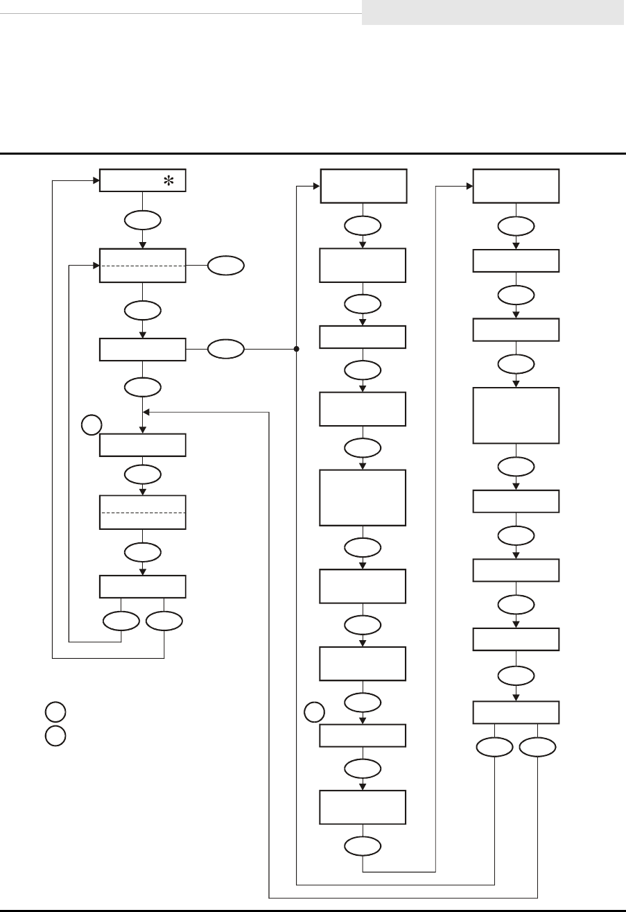
95741 Sixth Edition 6-23
SCSI View Configuration Status
■SCSI View Configuration Status
Figure 6-8 provides a menu tree for viewing a SCSI configuration.
Figure 6-8. Menu Tree—View SCSI Configuration
C53516
Tar Neg
(Y/N)
X
SCSI Bit
(16/8)
xx
Tape Bar
(Y/N)
X
VolSafe
(Y/N)
X
Full DSE
(Y/N)
X
Cmprss
Yes/Off/No)
Xxx
(
(Language)
SCSI
(Ultra/Slow
/Fast)
Xxxxxx
SCSI ID x
Toggle
CSL
/NONE)
XXXXX
(x.y.z
Select
(Select Online)
Online
Offline
No
Select
View CFG ?
Yes
Menu Select
Rx.yy.zzza
Exit Menu?
No Yes
CSL
(System/Auto
/Manual)
Xxxxxx
FullCode
(Y/N)
X
H=
xxxxxxxx
L=
yyyyyyyy
S/N=
zzzzzz
Exit CFG ?
Emul
XXXXX
Lib Adr xy
Menu
Select
No Yes
Menu
Menu
Menu
Menu
Menu
Menu
Menu
Menu
Menu
Menu
Menu
Menu
Menu
Menu
Menu
Menu
Menu
Menu
Menu
Menu
Menu
Notes:
1.
2.
Firmware release level.
C
urrent language selection.
1
2
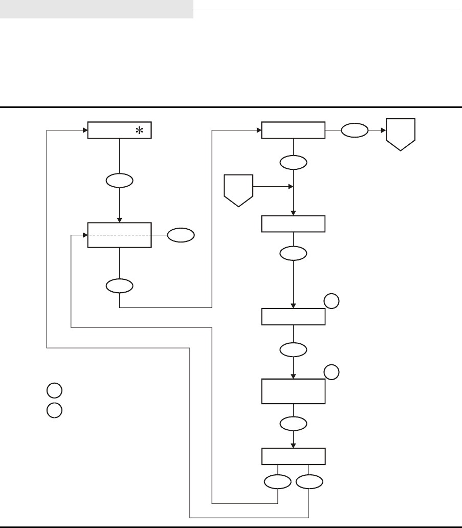
SCSI Change Configuration Menu
6-24 Sixth Edition 95741
■SCSI Change Configuration Menu
Figure 6-9 provides a menu tree for changing a SCSI configuration.
Figure 6-9. Menu Tree—Change SCSI Configuration (Sheet 1 of 2)
C53510
Notes:
.
1.
2
Firmware release number.
CSL Firmware release number only
appears when drive is installed in a CSL.
Menu
Toggle
Select
(Select Offline)
Online
Offline
Menu
Menu
Select
Exit Menu?
No Yes
No
Select
Chng CFG ?
Yes
Menu
Sheet 2
A
Sheet 2
B
Rx.yy.zzza
Menu
1
CSL
(x.y.z/NONE)
XXXXX
Menu
2
Drv Menu ?
Menu
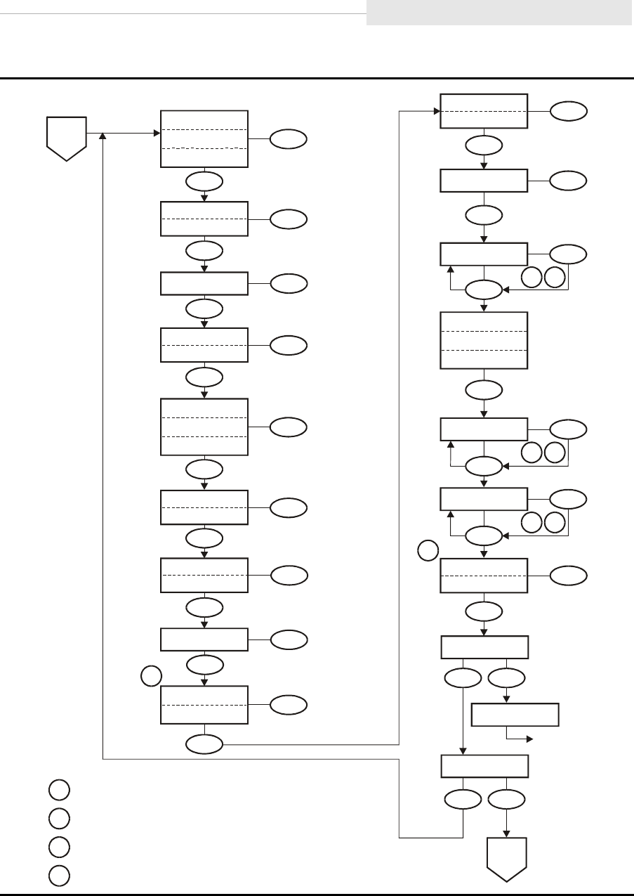
95741 Sixth Edition 6-25
SCSI Change Configuration Menu
Figure 6-9. Menu Tree—Change SCSI Configuration (Sheet 2 of 2)
C53979
FullCode Y
FullCode N
Select
Menu
1
VolSafe Y
VolSafe N
Select
Menu
Full DSE Y
Full DSE N
Select
Menu
Tape Bar Y
Tape Bar N
Select
Menu
Language ?
Select
Menu
Menu
Emul
XXXXX
Select
3
2
3
2
3
2
4
Lib Adr xy
Select
Menu
WWN Custom
WWW Normal
Select
Menu
Saving CFG
Save/IPL ?
IPL
Menu
Select
No Yes
Exit CFG ?
Menu
Select
No Yes
Select
Menu
H=xxxxxxxx
Select
Menu
L=yyyyyyyy
Menu
CSL System
CSL Auto
CSL Manual
Sheet 1
B
Cmprss Yes
Cmprss Off
Cmprss No
Select
Menu
Tar Neg Y
Tar Neg N
Select
Menu
SCSI 16Bit
SCSI 8Bit
Select
Menu
Port A
(ENA/DIS)
XXX
Select
SCSI ID x
Menu
SCSI Ultra
SCSI Slow
SCSI Fast
Select
Menu
Sheet 1
A
Notes:
1
2
3
4
Normal
resets
WWN
to
factory
preset.
VolSafe
Y
requires
password
from
StorageTek
Technical
Support.
When all digits are steady, press Menu to accept; or press Select
to restart change mode.
Press Select to step flashing digit. Press Menu to set.

SCSI Change Configuration Menu
6-26 Sixth Edition 95741
Table 6-2 provides detailed instructions to change configuration of a SCSI drive
when the drive is offline.
Table 6-2. Menu Table—SCSI Configuration
Options Notes Procedure
Online/Offline Main Menu
Online/
Offline
Defaults to Online at power-on.
Offline must be selected to
change configuration settings.
OffLn Pend may display while
waiting for a system response or
diagnostics completion.
1. If required, press Menu repeatedly
until Online or Offline is
displayed.
2. If Online, press Select to toggle
option to Offline.
3. Press Menu to advance to Change
Configuration main menu.
Change Configuration Main Menu
Chng CFG ? This is the entry point to the
Configuration submenus.
1. Press Select to enter
Configuration submenus, or
2. Press Menu to bypass.
Compress Mode Submenu
Cmprss Yes
Cmprss Off
Cmprss No
Defaults to last saved selection.
When Yes is selected, data is
compressed, by default. Host can
request no data compression.
When Off is selected, data is not
compressed, and host request has
no effect.
When No is selected, data is not
compressed, by default. Host can
request data compression.
1. Press Menu to bypass, or
2. Press Select until the desired
option is displayed; then, press
Menu to set, and advance to next
submenu.
Note: Manufacturing ships drive with the Cmprss Yes option selected.

95741 Sixth Edition 6-27
SCSI Change Configuration Menu
Data Security Erase Mode Submenu
Full DSE Y
Full DSE N
Defaults to last saved selection.
Full DSE Y writes a random
binary pattern on the media,
over-writing existing data, from
the point of an “Erase” command,
to the End of Tape.
Full DSE N writes data on the
media that indicates valid data
does not exist beyond the point
of an “Erase” command.
1. Press Menu to bypass, or
2. Press Select to toggle option;
then, press Menu to set, and
advance to next submenu.
Note: Manufacturing ships drive with the Full DSE Y option selected.
SCSI ID Submenu
SCSI ID x Defaults to last saved selection.
Pressing Select when the x
character is steady, starts the
change mode. The X character
begins flashing and will
increment up, one value with
each additional press of Select.
Pressing Menu sets flashing
character at displayed value.
Establishes the SCSI ID of the
drive. The value range 0–7 is for
narrow (8bit) bus width, and
0–F is for wide (16bit) bus width.
1. Press Select to start change mode;
or, press Menu to bypass.
2. Press Select to increment
until desired value is displayed,
then press Menu to set.
3. Press Menu to advance to the next
submenu; or, press Select to
restart change mode.
Note: Manufacturing ships drive with the SCSI ID 6 address option selected.
SCSI Target Negotiation Mode Submenu
Targ Neg Y
Targ Neg N
Defaults to last saved selection.
When Yes is selected, it allows
the drive control unit to initiate
negotiations with the host to
clarify the SCSI transmission
speed, in case the host had not
done so.
1. Press Menu to bypass, or
2. Press Select to toggle option;
then, press Menu to set, and
advance to next submenu.
Note: Manufacturing ships drive with the Targ Neg N option selected.
Table 6-2. Menu Table—SCSI Configuration (Continued)
Options Notes Procedure

SCSI Change Configuration Menu
6-28 Sixth Edition 95741
SCSI Bus Speed Submenu
SCSI Ultra
SCSI Fast
SCSI Slow
Defaults to last saved selection.
Selects channel transmission
speed for the drive to match the
drive with the host capabilities.
Ultra = 40MB/s (16Bit width)
20MB/s ( 8Bit width)
Fast = 20MB/s (16Bit width)
10MB/s ( 8Bit width)
Slow = 10MB/s (16Bit width)
5MB/s ( 8Bit width)
1. Press Menu to bypass, or
2. Press Select until the desired
option is displayed; then, press
Menu to set, and advance to next
submenu.
Note: Manufacturing ships drive with the SCSI Ultra option selected.
SCSI Bus Width Submenu
SCSI 16Bit
SCSI 8Bit
Defaults to last saved selection.
Selects channel width for the
drive to match the drive with the
host configuration.
1. Press Menu to bypass, or
2. Press Select to toggle option;
then, press Menu to set, and
advance to next submenu.
Note: Manufacturing ships drive with the SCSI 16Bit option selected.
Tape Bar Submenu
Tape Bar Y
Tape Bar N
Selects a barchart that displays
how much tape is written and
how much tape has been read.
Deselects the barchart display.
See “Tape Bar” on page 1-14 for
additional information.
1. Press Menu to bypass, or
2. Press Select to toggle option;
then, press Menu to set, and
advance to the next submenu.
Note: Manufacturing ships drive with the Tape Bar N option selected
Language Selection Submenu
Language ? Selects display language:
English, Espanol, Francais,
Italiano, or Deutscher.
1. Press Menu to bypass, or
2. Press Select until desired option
is displayed; then, press Menu to
set, and advance to the next
submenu.
Note: Manufacturing ships drive with the English option selected
Table 6-2. Menu Table—SCSI Configuration (Continued)
Options Notes Procedure

95741 Sixth Edition 6-29
SCSI Change Configuration Menu
VolSafe Selection Submenu
VolSafe Y
VolSafe N
Defaults to last saved selection.
When VolSafe Y is selected, a
password (Contact StorageTek
Technical Support) must also be
entered before VolSafe is enabled.
When VolSafe N is selected,
VolSafe is disabled.
1. Press Menu to bypass, or
2. Press Select to toggle option;
then, press Menu to set.
3. If applicable, press Select to start
password entry. The left-most
character begins flashing.
4. Press Select to increment until
desired character is displayed,
then press Menu to set.
5. Repeat step 4 for each character.
6. Press
Menu
to advance to the next
submenu;
or
, press
Select
to restart.
Note: Manufacturing ships drive with the VolSafe N option selected.
Full Code Load Submenu
FullCode Y
FullCode N
Defaults to last saved selection.
When FullCode Y is selected,
all drive code images are
downloaded to the EEPROM. This
enables the drive to be used to
create a code tape with all images
which then could be used to
update other drives.
When FullCode N is selected,
only the specific code image for
the drive is downloaded to
EEPROM. This option allows
more EEPROM space for dumps
and event logs, but disables the
drive from creating code tapes.
1. Press Menu to bypass, or
2. Press Select to toggle option;
then, press Menu to set, and
advance to the next submenu.
Note: Manufacturing ships drive with only one code image, and FullCode N selected.
CodCrFail3
displays if you try to make a code tape from a drive with only one
image loaded. (
Code release level 1.30.109 and up, displays CHK A738.)
To enable a drive to create code tapes, select FullCode Y, and load the desired
code release level from a valid source.
Table 6-2. Menu Table—SCSI Configuration (Continued)
Options Notes Procedure

SCSI Change Configuration Menu
6-30 Sixth Edition 95741
Emulation Mode Submenu
Emul XXXXX Defaults to last saved selection.
Emul STD is Native.
Emul 3590 is 3590B (AS400).
Emul SD-3
Emul 3
Emul F2483
Emul 5
Emul 3490E is 3490E11 (AS400).
Emul 7
Emul STD s
Emul 3590s
Emul 11
Emul 12
Emul 13
Emul 14
CAUTION:
DECREASED CAPACITY.
Emul STD s and Emul 3590s
selections use a portion of
tape length for recording.
DO NOT USE these selections
unless instructed to do so by
StorageTek Engineering.
1. Press Menu to bypass, or
2. Press Select until desired option
is displayed; then, press Menu to
set and advance to the next
submenu.
Note: Manufacturing ships drive with the Emul STD option selected.
Std identifies the drive to the host relative to actual (Native) model.
Table 6-2. Menu Table—SCSI Configuration (Continued)
Options Notes Procedure

95741 Sixth Edition 6-31
SCSI Change Configuration Menu
Library Address Submenu
Lib Adr xy Defaults to last saved selection.
Pressing Select when both
characters are steady, starts the
change mode. The x character
begins flashing and will
increment up, one value with
each additional press of Select.
Pressing Menu sets flashing
character at displayed value (0-F),
and advances to the y character.
For 9738 libraries, the addresses
of all drives stay at the factory
preset (FF).
1. Press Select to start change mode;
or, press Menu to bypass.
2. Press Select to increment
until desired value is displayed,
then press Menu to set.
3. Repeat step 2 for y character.
4. Press Menu to advance to the next
submenu; or, press Select to
restart change mode.
Note: Manufacturing ships drive with Lib Adr FF selected.
CSL Power On Mode Submenu
CSL System
CSL Auto
CSL Manual
Defaults to last saved selection.
Selects the default operation of
the CSL when powering on:
•CSL System allows the host
to control the CSL.
•CSL Auto allows the CSL to
operate automatically.
•CSL Manual allows manual
operations only.
1. Press Menu to bypass, or
2. Press Select until desired option
is displayed; then, press Menu to
set and advance to next
submenu.
Note: Manufacturing ships drive with CSL Auto option selected.
Table 6-2. Menu Table—SCSI Configuration (Continued)
Options Notes Procedure

SCSI Change Configuration Menu
6-32 Sixth Edition 95741
Drive Node World-Wide Name Submenu
Note: Firmware release level 1.30.111, and up, can create a “Custom” WWN as required for
special circumstances.
Make sure a Custom WWN is unique, and registered in Host interface software.
Unregistered or duplicate WWNs will cause Host interface anomalies.
H=xxxxxxxx
L=yyyyyyyy
Defaults to last saved selection.
H=xxxxxxxx, together with
L=yyyyyyyy, comprise the
unique 64-bit WWN that identifies
this specific drive.
Pressing Select when all digits are
steady, starts the change mode.
The left-most hexadecimal digit
begins flashing and will
increment up one value with
each additional press of Select.
Pressing Menu sets the flashing
digit at displayed value (0-F), and
advances flashing to the next
digit. When the last digit is set, a
second press of Menu advances
menu to next submenu. Pressing
Select restarts the left-most digit
flashing.
1. Press Select to start change mode;
or, press Menu to bypass.
2. Press Select to increment digit
until desired value is displayed,
then press Menu to set.
3. Repeat step 2 for each digit.
4. Press Menu to advance to the next
submenu; or, press Select to
restart change mode.
Drive Node Custom/Normal WWN Submenu
Note: This submenu only appears if a Custom WWN is in use, or is being created.
WWN Custom
WWN Normal
Custom is default selection.
Normal selection recalls the
stored Normal WWN from the
drive EEPROM.
Currently, a password (use 500) is
required to save a new Custom
WWN, or to reset a Custom WWN
back to the stored Normal WWN.
Password requirement will not be
in future firmware releases.
1. Press Menu to invoke Custom
WWN, and advance to the next
submenu; or,
2. Press Select to toggle option;
then, press Menu to reset WWN to
the stored Normal WWN, and
advance to the next submenu.
Note: If valid password is not entered, change to the WWN will not be saved.
Table 6-2. Menu Table—SCSI Configuration (Continued)
Options Notes Procedure

95741 Sixth Edition 6-33
SCSI Change Configuration Menu
Save Configuration Submenu
Save/IPL ? This submenu appears only if the
drive configuration was changed.
Saving CFG displays for 2
seconds after pressing Select.
After saving configuration,
a SCSI drive automatically
performs IPL.
Save Fails displays for RAM
problems. See Table 7-2 on
page 7-3 for instructions.
1. Press Select (Yes) to save changes
and initiate IPL; or,
2. Press Menu (No) to cancel
changes.
Exit Configuration Submenu
Exit CFG ? This submenu allows you to exit
CFG, or to repeat the CFG
submenus.
1. Press Select (Yes) to exit CFG, or
2. Press Menu (No) to loop back to
the Compress Mode Submenu.
Main Exit Main Menu
Exit Menu? This menu allows you to exit the
menu system, or to stay in, with
an opportunity to return the drive
to Online before exiting the menu
system.
If the drive is not returned to
Online before exiting the menu
system, the display will flash
Offline every few seconds as a
reminder that drive is still Offline.
1. Press Select (Yes) to exit the
menu system, or
2. Press Menu (No) to return to the
Online/Offline main menu.
3. If applicable, IPL the drive to
invoke the changes.
Table 6-2. Menu Table—SCSI Configuration (Continued)
Options Notes Procedure
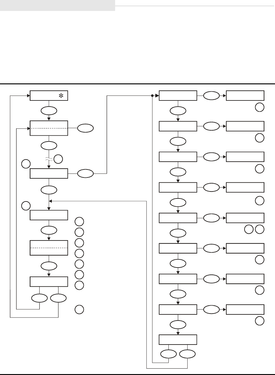
Drive Operations Menu
6-34 Sixth Edition 95741
■Drive Operations Menu
Figure 6-10 provides a menu tree for drive operations. This menu is only
available when the drive is Offline. Each option invokes a submenu to bypass,
or perform the listed tape utility.
Figure 6-10. Menu Tree—Drive Operations
C53513
Exit Drv ?
Menu
Select
No
Yes
Toggle
Select
(Select Offline)
Online
Offline
No
Select
Drv Menu ?
Yes
No
Rx.yy.zzza
CSL
( /NONE)
XXXXX
x.y.z
Exit Menu?
Menu Select
No Yes
Menu
Menu
Menu
Menu
Menu
Select
Yes
IPL FromTP Ld IPL Tp
Select
Yes
MakeDumpTp Ld Dump Tp
Select
Yes
MakeCodeTp
Ld Code Tp
Select
Yes
MakeDataTp
Ld Data Tp
Select
Yes
Build MIR
Ld Cust Tp
Menu
No
Menu No
Menu No
Select
Yes
W/R Diag
LdScrtchTp
Select
Yes
SrvoHdDiag
Select
Yes
SrvoLdUnld
Menu
No
Menu
No
Menu
No
Menu No
Menu No
LdScrtchTp
LdScrtchTp
Notes:
1.
2.
.
4
5.
6.
See interface Menu Tree.
Offline only.
Firmware
release
number.
Insert
Firmware
tape.
Insert
Write-Enabled
tape.
Insert
tape
requiring
MIR.
If
using
a
CSL
to
build
the
MIR
on
a
tape,
press
the
start
switch
to
load
a
tape
after
inserting
into
the
feed
channel.
Insert
known
good
scratch
tape.
3
.
7.
8.
1
3
2
5
5
5
4
76
8
8
8

95741 Sixth Edition 6-35
Drive Operations Menu
Table 6-3 provides detailed instructions to:
•Update drive firmware
•Format a dump tape
•Copy firmware
•Reformat tapes
•Build an MIR
•Perform drive diagnostics.
Table 6-3. Menu Table—Drive Operations
Options Notes Procedure
Online/Offline Main Menu
Online/
Offline
Defaults to Online at power-on.
Offline must be selected to
enter Drive Operation menus.
OffLn Pend may display
while waiting for a system
response or diagnostics
completion.
1. If required, press Menu repeatedly
until Online or Offline is
displayed.
2. If Online, press Select to toggle
option to Offline.
3. Press Menu repeatedly until
Drv Menu ? is displayed.
Drive Operation Main Menu
Drv Menu ? This is the entry point to the
Drive Operations submenus.
1. Press Select to enter the Drive
Operations submenus, or
2. Press Menu to bypass the Drive
Operations submenus.

Drive Operations Menu
6-36 Sixth Edition 95741
Code Update Submenu
IPL FromTP IPL From Tape, updates the
drive firmware from a firmware
tape inserted in the drive.
If a normal tape is present in
the drive when this function is
activated, it ejects.
When the update is done, the
drive automatically ejects the
firmware tape, performs IPL,
and goes Online.
If CodUpFailsx (Code
Update Fail Number x) or
CHK xxxx displays, refer to
Table 7-2 on page 7-3 for
instructions.
1. Press Menu to bypass, or
2. Press Select to activate.
3. When Ld IPL Tp displays, insert
the write-protected firmware tape
containing the desired code level.
Dump Tape Submenu
MakeDumpTp Make Dump Tape, formats a
tape; but, it does not collect
diagnostic data. Tapes used to
obtain dump data must first be
formatted this way to accept
dump data.
If a normal tape is present in
the drive when this function is
activated, it ejects.
Old data on tape being
formatted will be erased.
If DmpCrFailx (Dump Create
Fail Number x) or CHK xxxx
displays, refer to Table 7-2 on
page 7-3 for instructions.
1. Press Menu to bypass, or
2. Press Select to activate.
3. When Ld Dump Tp displays, insert
a write-enabled tape.
4. When the tape ejects, insert another
tape, or press Menu to advance to
the next submenu.
Table 6-3. Menu Table—Drive Operations (Continued)
Options Notes Procedure

95741 Sixth Edition 6-37
Drive Operations Menu
Create Code Tape Submenu
MakeCodeTp Make Code Tape, copies all
firmware images from the drive
EEPROM to a tape. This tape
may then be used to update
other drives using the Code
Update submenu.
If a normal tape is present in
the drive when this function is
activated, it ejects.
If CodCrFailx (Code Create
Fail Number x) or CHK xxxx
displays, refer to Table 7-2 on
page 7-3 for instructions.
CodCrFail3 or CHK A738
displays if you try to make a
code tape form a drive which
has only one image loaded.
1. Make sure FullCode option is set to
Yes. If required, exit Drive
Operations Menu and enter Change
Configuration Menu to change
option.
2. Press Menu to bypass, or
3. Press Select to activate.
4. When Ld Code Tp displays, insert
write-enabled tape.
5. When the tape ejects, insert another
tape, or press Menu to advance to
the next submenu.
6. Write-protect the new code tape.
Note: Only drives set to FullCode Y and which have all images loaded into EEPROM
can make valid code tapes.
Reclaim Tape Submenu
MakeDataTp Make Data Tape, reformats
tapes so they can be reused as
normal data tapes. This is
referred to as “reclaiming.”
If a normal tape is present in
the drive when this function is
activated, it ejects.
Old data on tape being
formatted will be erased.
If DatCrFailx (Data Create
Fail Number x) or CHK xxxx
displays, refer to Table 7-2 on
page 7-3 for instructions.
1. Press Menu to bypass, or
2. Press Select to activate.
3. When Ld Data Tp displays, insert
write-enabled tape.
4. When tape ejects, insert another
tape, or press Menu to advance to
the next submenu.
Table 6-3. Menu Table—Drive Operations (Continued)
Options Notes Procedure

Drive Operations Menu
6-38 Sixth Edition 95741
Build Media Information Region (MIR)
Build MIR The 9840 tape drive uses
information recorded at the
beginning of each tape, in an
area known as the Media
Information Region (MIR), to
access and manage that tape
while mounted on the drive.
Make sure drive is unloaded
before activating Build MIR.
Rebuild MIR flashes on the
operator panel while the MIR is
rebuilding.
A 9840 MIR rebuild takes
approximately 40 minutes for a
full tape.
If BldMIRFail (Build MIR
Fail) or CHK xxxx displays,
refer to Table 7-2 on page 7-3
for instructions.
1. Press Menu to bypass, or
2. Press Select to activate.
3. When Ld Cust Tp displays,
insert tape requiring MIR.
4. If using a CSL to build the MIR on a
tape, press the Start switch to load
the tape after inserting it into the
feed channel.
5. When the MIR is rebuilt, and the
tape ejects, insert another tape, or
press Menu to advance to the Exit
Drive Submenu.
Table 6-3. Menu Table—Drive Operations (Continued)
Options Notes Procedure

95741 Sixth Edition 6-39
Drive Operations Menu
Write/ Read Diagnostic Submenu
W/R Diag Write/Read Diagnostics test the
drive write/read function by
writing/reading data to/from a
scratch tape.
A tape cartridge, if present,
ejects when this option is
selected.
Make sure a known good,
scratch (formatted for data) tape
cartridge is available. The
diagnostic routine is designed
and intended to check drive
functions, NOT tape media. A
faulty tape cartridge will cause
unexpected/misleading errors.
“WrtRd Diag” displays
during the approximately
5 minute routine.
If CHK xxxx displays, see FSC
Dictionary for information.
1. Press Menu to bypass, or
2. Press Select to activate.
3. When LdScrtchTp displays, insert
known good, write-enabled scratch
tape cartridge.
4. If a diagnostic error FSC displays,
press Unload to clear.
5. When the tape ejects, press Menu to
advance to the Exit Drive submenu;
or, reinsert tape cartridge to repeat.
Note: The following Drive Diagnostics Submenu Item is not currently functional,
although it appears as a menu option after firmware release level 1.30.109.
Not Available will display whenever you attempt to exercise this option until
it is activated in a future firmware release.
Servo Head Diagnostic Submenu
SrvoHdDiag Servo Head Diagnostics test the
drive servo head function.
Not currently available.
1. Press Menu to bypass
Table 6-3. Menu Table—Drive Operations (Continued)
Options Notes Procedure

Drive Operations Menu
6-40 Sixth Edition 95741
Servo Load/ Unload Diagnostic Submenu
SrvoLdUnld Servo Load/ Unload Diagnostics
test the drive servo load/unload
function.
A tape cartridge, if present,
ejects when this option is
selected.
Make sure a scratch tape
cartridge is available. Tape
cartridge loading is required for
the diagnostic, but the tape
media is not used.
TestSrvLdU displays during
the approximately 1 minute
routine
(10 load/unload cycles).
If CHK xxxx displays, see FSC
Dictionary for information.
1. Press Menu to bypass, or
2. Press Select to activate.
3. When LdScrtchTp displays, insert
known good scratch tape cartridge.
4. If a diagnostic error FSC displays,
press Unload to clear.
5. When the tape ejects, press Menu to
advance to the Exit Drive submenu;
or, reinsert tape cartridge to repeat.
Exit Drive Submenu
Exit Drv ? This submenu allows you to
exit Drive Operations, or to
repeat the drive operations
submenus.
1. Press Select (Yes) to exit Drive
Operations, or
2. Press Menu (No) to loop back to
the Code Update Submenu.
Table 6-3. Menu Table—Drive Operations (Continued)
Options Notes Procedure
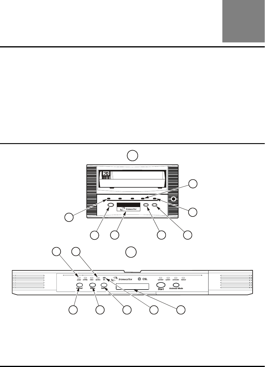
95741 Sixth Edition 7-1
7
Error and Recovery
This chapter provides 9840 Tape Drive error and recovery procedures.
Note: Refer to “Error and Recovery” in Chapter 5, “Cartridge Scratch Loader”
for specific CSL error and recovery instructions.
■Power and Service Error Indicators
Figure 7-1 provides the location of items on the standard and CSL operator
panel. Table 7-1 on page 7-2 provides a description of the action recommended
to clear the suspected malfunction.
Figure 7-1. Operator Panels
A is the standard operator panel.
1. service Indicator
2. IPL Switch
3. Select Switch
4. Menu Switch
B is the CSL operator panel.
5. Display
6. Unload Switch
7. power Indicator
C53677
service
65
7
71
1
A
B
2
34
243
5
6

Dislodge a Stuck Tape
7-2 Sixth Edition 95741
Table 7-1 explains error indications shown by the power and service indicators.
These errors do not create an error message on the alphanumeric display. Refer
to Table 7-2 on page 7-3 for error displays and recovery instructions.
■Dislodge a Stuck Tape
When you press the Unload switch (6, Figure 7-1 on page 7-1)or when the
unload function is electronically triggered, and the cartridge fails to eject, it
indicates that the tape cartridge is stuck or jammed within the carriage.
Note: See “Jammed Cartridge” in Chapter 8, “Servicing the Drive,” for
instructions to remove the cartridge from a drive.
See “Jammed Cartridge” in Chapter 5, “Cartridge Scratch Loader,”for
instructions to remove the cartridge from a CSL.
Table 7-1. Power and Service Indicators
power
(7, Figure 7-1)
service
(1, Figure 7-1)Meaning Action
On Off Normal operation
is occurring.
No action necessary.
On or flashing Flashing after
dump
collection
A 9840 Tape Drive
error is detected.
Perform an IPL.
If the problem
persists, contact
authorized service
personnel.
Flashing while
action takes
place
Flashing or off A 9840 Tape Drive
error occurred.
Power-on and IPL
sequences occur
automatically.
No action necessary.
If repeated power-on
and IPL sequences do
not make the drive or
CSL operational,
contact authorized
service personnel.
Continuous
flashing
Flashing or off The 9840 Tape
Drive failed the
power on
procedure; it
cannot exit the IPL
mode.
Retry the power on
and IPL procedure.
If the problem
persists, contact
authorized service
personnel.
On On A 9840 Tape Drive
failure occurred.
Perform an IPL.
If the problem
persists, contact
authorized service
personnel.

95741 Sixth Edition 7-3
Dislodge a Stuck Tape
Table 7-2 provides an alphabetical list of operator panel error displays and
recommended actions. Refer to Figure 7-1 on page 7-1 for switch, indicator, and
display locations on the standard and CSL operator panels.
The notation “xxxx” is a four-character hexadecimal fault symptom code (FSC).
Note: Refer to “Error and Recovery” in Chapter 5, “Cartridge Scratch Loader,”
for additional errors for the CSL.
Table 7-2. Error Displays and Instructions
Display Probable Cause Recommended Action
*A steady asterisk (*) indicates
that the drive completed IPL,
and is online but not loaded.
Operator discretion.
*
Offline
An asterisk (*) alternating
with Offline indicates that
drive or CSL is offline.
Operator discretion.
Place drive Online for use by the host.
ASIA DIAGS This is the normal display
during IPL.
Wait for IPL to complete.
Bank n Bad During a boot, a section of
memory (n=1, 2, 3, or 4) is
found bad.
If IPL does not correct the problem, replace
the drive or CSL.
Boot Fail The IPL failed. Initiate IPL again.
If IPL fails again, replace the drive or CSL.
BT Monitor A sequence of switches took
you to an Engineering zone.
IPL the drive or CSL to clear the error.
BldMIRFail Rebuild of tape Media
Information Region (MIR)
unsuccessful.
Note: In code level 1.30.109 and up, error message is replaced by CHK xxxx.
cnhndnsnThe hardware revision level
supported by the firmware in
this drive, where:
n=any number 0–9,
c=controller processor level
h=host side formatter level
d=device side formatter level
s=servo level.
This message occurs when the firmware
level is insufficient to control the hardware
level in the drive.
Install newer firmware level.
CC DIAG This is the normal display
during IPL.
Wait for the IPL to complete.

Dislodge a Stuck Tape
7-4 Sixth Edition 95741
CHK xxxx An operational failure
occurred. (xxxx = actual
FSC that caused the failure.)
Some failures will initiate a
diagnostic dump and IPL.
If required, wait for the IPL to complete,
then retry the operation.
If the retry fails, replace drive or CSL.
*Cleaning* The cleaning tape was
inserted and the drive or CSL
is now in process of cleaning.
No action necessary.
CodCrFail1 Unable to write to tape.
Unable to position on tape.
Make sure the tape is write-enabled.
Try another tape.
Note: In code level 1.30.109 and up, error message is replaced by CHK xxxx.
CodCrFail2 Unreadable tape format. Reclaim as a data tape.
Retry the operation.
Try another tape.
Note: In code level 1.30.109 and up, error message is replaced by CHK xxxx.
CodCrFail3 Drive only has single code
image in the EEPROM.
Make sure that the drive has all code
images loaded in the EEPROM.
Note: In code level 1.30.109 and up, error message is replaced by CHK A738.
CodeUpDate The firmware in the drive or
CSL is being updated from the
host; the operator panel
switches are locked.
No action necessary.
CodUpFail1 Unable to read the tape.
Unable to position on tape.
Unable to read image on
tape.
Try another tape.
Note: In code level 1.30.109 and up, error message is replaced by CHK xxxx.
CodUpFail2 The EEPROM is bad. Before initiating IPL, try another tape.
Initiate an IPL.
If the problem persists, replace the drive or
CSL.
Note: In code level 1.30.109 and up, error message is replaced by CHK xxxx.
Table 7-2. Error Displays and Instructions (Continued)

95741 Sixth Edition 7-5
Dislodge a Stuck Tape
CodUpFail3 The tape format is
unreadable.
Reclaim as a data tape, recreate code tape.
Retry the operation.
Try another tape.
Note: In code level 1.30.109 and up, error message is replaced by CHK xxxx.
CodUpFail4 This is not a code-update
tape.
Retry with the correct tape.
Note: In code level 1.30.109 and up, error message is replaced by CHK xxxx.
DatCrFail1 Unable to create (format) a
data tape.
Make sure the tape is write-enabled.
Try another drive or CSL.
Note: In code level 1.30.109 and up, error message is replaced by CHK xxxx.
DmpCrFail1 Unable to create (format) a
dump tape.
Make sure the tape is write-enabled.
Try another tape.
Try another drive or CSL.
Note: In code level 1.30.109 and up, error message is replaced by CHK xxxx.
DmpCrFail2 The tape format is
unreadable.
Reclaim as a data tape.
Retry the operation.
Try another tape.
Note: In code level 1.30.109 and up, error message is replaced by CHK xxxx.
DumpToHost The dump or event log is
being transferred to host; the
operator panel switches are
locked
No action necessary.
DmpWrFail1 Unable to write a dump to
tape.
Unable to position on tape.
Try another tape.
Make sure the tape is formatted for a
dump.
Note: In code level 1.30.109 and up, error message is replaced by CHK xxxx.
DmpWrFail2 No dump to process. Force a diagnostic dump.
Note: In code level 1.30.109 and up, error message is replaced by CHK xxxx.
DumpAgain? The drive or CSL detected the
same “CHK (xxxx)” within
one minute.
Go to “DumpAgain? Indication” on
page 7-12.
Exp ClCart The cleaning cartridge is used
up.
Replace the cleaning cartridge.
Table 7-2. Error Displays and Instructions (Continued)

Dislodge a Stuck Tape
7-6 Sixth Edition 95741
xxxx:Dmpyy Alternates with an asterisk (*)
after completion of an IPL,
where:
xxxx = FSC of the last dump
data saved to the EEPROM
yy = number of uncollected
dumps in EEPROM
Optionally move the dump(s) to the host
or tape
See the dump instructions in Chapter 4,
“Getting Started,” or Chapter 7, “Error and
Recovery.”
Note: In code level 1.30.109 and up, error message is replaced by CHK xxxx.
Fix_CfgErr Upon IPL, the configuration
checksum does not match.
Go to “Save Fails or Fix_CfgErr Indication”
on page 7-9.
INIT(xxxx)An initialization error
occurred.
Initiate IPL.
If that fails, replace the drive or CSL.
IPL Pend This is displayed for one
second when the IPL switch is
pressed.
Wait until the IPL completes automatically.
Load CC The common controller code
is loading.
No action necessary.
Loading The tape cartridge is being
loaded.
No action necessary.
Load FIBRE This is the normal display
during a boot.
Wait for the IPL to complete.
Load(xxxx)The load or unload operation
failed.
If another tape also fails to load, IPL the
drive or CSL.
If the failure persists, replace the drive or
CSL.
If another tape works, the tape is suspect.
Load SCSI This is the normal display
during a boot.
Wait for the IPL to complete.
Locating The drive or CSL is
performing a high-speed
seek.
No action necessary.
Memory Err The RAM failed during an IPL. Initiate IPL again. If that fails, replace the
drive or CSL.
NT Ready A A VolSafe tape is in process of
manual unload.
Wait until unload operation completes
NT Ready F A write-protected tape is in
process of manual unload.
Wait until unload operation completes
Table 7-2. Error Displays and Instructions (Continued)

95741 Sixth Edition 7-7
Dislodge a Stuck Tape
NT Ready U A non-write protected tape is
in the process of a manual
unload.
Wait until unload operation completes.
Offline
*
Offline alternating with an
asterisk (*) indicates that the
drive or CSL is offline.
Operator discretion.
Note: Place drive or CSL Online for use
by the host.
Online The drive or CSL is
operational.
No action necessary.
Power Fail The power supply failed. Replace the power supply.
Reading The drive or CSL is in read
mode.
No action necessary.
Ready A All of the following
conditions must exist:
•The loaded tape is a
VolSafe tape.
•The VolSafe tape is write-
enabled (write-protect
switch unlocked).
•The drive or CSL has the
VolSafe function enabled.
Operator discretion.
Note: Refer to “Cartridges” in Chapter 1, “Introduction,” for more information on VolSafe
cartridges.
Ready F The loaded tape is file-
protected.
A VolSafe tape is loaded into
a drive or CSL which has
VolSafe disabled.
Operator discretion.
No action required to read the VolSafe
tape.
To append data to a VolSafe tape, enable
drive or CSL and ensure the write-protect
switch is unlocked.
Note: If the drive sensor is defective, all VolSafe cartridges will read Ready F.
If a VolSafe cartridge is loaded in a drive or CSL that does not support VolSafe
(downlevel code), FSC 4AF6 is displayed.
Ready U The loaded tape is not file-
protected.
Operator discretion.
Rewinding The drive or CSL is rewinding. No action necessary.
Save Fails The new configuration cannot
be saved.
Replace the drive or CSL.
Table 7-2. Error Displays and Instructions (Continued)

Dislodge a Stuck Tape
7-8 Sixth Edition 95741
SavingDump This is displayed while saving
the dump to EEPROM.
This is the normal display.
Wait for the dump to complete.
Start Init Initialization started. No action necessary.
Trapped The boot is trapped in a
closed loop.
If the IPL does not clear the condition,
replace the drive or CSL.
Unloading The tape cartridge is being
unloaded.
No action necessary.
UnWr(xxxx)The Unload switch was
pressed while a write was
taking place.
Go to “UnWr xxxx Indication” on
page 7-12.
Write Prot The drive or CSL attempted to
write to a write-protected
tape.
A VolSafe tape is loaded and
the operator is trying to make
a dump, code, or data tape,
or build an MIR.
Change the switch on tape cartridge to
write-enable.
Remove VolSafe tape and insert a standard
cartridge.
Writing The drive or CSL is in write
mode.
No action necessary.
Table 7-2. Error Displays and Instructions (Continued)

95741 Sixth Edition 7-9
Save Fails or Fix_CfgErr Indication
■Save Fails or Fix_CfgErr Indication
This section contains specific information to clear a Save Fails or Fix_CfgErr
errors.
Explanation of Operations
Save New Configuration Change
When you make configuration changes, you save them to the RAM. The RAM
copy is in turn stored in the EEPROM.
The ASIA (Application Specific Interface Adaptor) looks at the entire RAM
contents, generates a checksum, and stores it in the EEPROM.
During normal operation, the drive uses the RAM content to determine drive
configuration, and the EEPROM remains idle. Note that while drive power is on,
the RAM periodically rewrites (refreshes) the EEPROM.
EEPROM versus RAM
The EEPROM is a non-volatile storage in which the drive configuration is saved
through power on/off cycles.
The RAM is the volatile working memory used by the drive to hold the
configuration data while it is powered on.
When powering off, the RAM content is lost, and the drive configuration is
retained only in the EEPROM.
After Power On or IPL
When the drive is powered on or an IPL is manually initiated, the EEPROM
contents are sent to the RAM. This data includes both the configuration data
and the previously stored checksum.
The ASIA reads the RAM, generates a new checksum, and compares it to the
previously stored checksum, looking for a match.
Fix_CfgErr” Error Indication
This error may occur during power on or IPL. The ASIA reads the RAM,
generates a fresh checksum from the RAM contents it sees, and compares this
checksum to the stored checksum. If there is no match, it shows up as a
Fix_CfgErr display. This may indicate a defective EEPROM or RAM.
Save Fails Error Indication
This error may occur when you save a new configuration to the RAM after
making configuration changes. It usually indicates a defective RAM.

Save Fails or Fix_CfgErr Indication
7-10 Sixth Edition 95741
Save Fails Error
This error can occur when saving a new configuration. It means that the RAM
has failed the save operation. The drive cannot work properly with defective
information in the RAM. Replace the drive.
Fix_CfgErr Error
This error can occur following power on or IPL: the drive configuration data
was sent from the EEPROM to the RAM, and the RAM data failed the ASIA
checksum test. When this error occurs, the drive completes the IPL but remains
offline.
CAUTION:
This error check does not protect you from entering the wrong
configuration in the first place. It only tells you that the RAM content had
somehow changed since the configuration data was last entered. If you
originally entered a wrong configuration and the circuits are in working
order, it will not show up as an error.
This error check does not lock drive operations. You can place the drive
online without changing the drive configuration. Do so only if you
determine that an unused bit in the RAM or EEPROM is bad in
accordance with the following procedure.
1. Check the drive configuration against the client records.
2. If the client records and the drive configurations match, there are two
possibilities:
•An unused bit in the RAM or EEPROM has become bad.
•There may be a problem with the ASIA interface.
3. To isolate one of the two possibilities, do the following:
a. Re-save the configuration.
Because the configuration is already apparently correct, re-saving the
configuration will generate and store a new checksum.
If an unused bit of the RAM has become bad, it is now included in the
ASIA checksum and will not show up again as an error.
b. Initiate an IPL of the drive.
c. If the error is not repeated, it is an indication that an unused bit in the
RAM is bad. This problem can now be disregarded. Go to Step 5.
d. If the problem is repeated and the configuration remains correct, there
may be a problem with an unused bit in the EEPROM or with the ASIA
checksum circuit.

95741 Sixth Edition 7-11
Save Fails or Fix_CfgErr Indication
Note: When the configuration in the RAM is correct, the drive can
usually operate normally while it remains powered on, even if
the EEPROM or the checksum circuit in the ASIA are damaged.
You can employ the drive that way if you have to wait for
replacement.
4. If the client and drive configurations do not match, there are two
possibilities:
•A damaged used area of the RAM
•A damaged used area of the EEPROM
Reconfigure the drive and save the new configuration:
a. If a used area of the RAM is bad, the save operation will fail, causing a
Save Fails error. In that case the Fix_CfgErr was caused by a bad
RAM and the drive must be replaced.
b. If the save operation succeeds, the EEPROM is probably bad. The new
configuration is properly saved only to the RAM: the EEPROM may have
corrupt data.
Note: When the configuration in the RAM is correct, the drive can
usually operate normally while it remains powered on, even if
the EEPROM is damaged. You can employ the drive that way if
you have to wait for replacement.
5. If applicable, return drive to the operator.
6. If the EEPROM is suspect, record the problem in the site’s logbook.
7. If the configuration problem repeats on the next IPL, it means that the
EEPROM is damaged and the drive should be replaced: you can, however,
reconfigure the drive and use it until a new drive is available.

UnWr xxxx Indication
7-12 Sixth Edition 95741
■UnWr xxxx Indication
UnWr xxxx means Unwritten Data. This message will display if the Unload
switch (6, Figure 7-1 on page 7-1) was pressed during a write operation. It
indicates that the drive attempted to write the remaining data before it unloaded
but the attempt failed and some data remains unwritten to tape.
CAUTION:
Pressing the Unload switch again will cause loss of this data.
The host may save the unwritten data by issuing the following command
sequence before pressing the Unload switch a second time: “Recover Buffer
Data.”
■DumpAgain? Indication
The “DumpAgain?” display alternates with a “CHK xxxx” fault symptom code
indication while the service indicator (1, Figure 7-1 on page 7-1) flashes. This
occurs when the identical “CHK xxxx” fault symptom code is detected within
one minute. The drive then becomes non-operational and requires manual
intervention.
With this condition, you may choose to initiate a dump but there is no
requirement to do so. If you have reason to initiate the dump, press any control
except the IPL switch (2, Figure 7-1 on page 7-1). This saves the dump data to
the EEPROM.
While the dump is being saved to the EEPROM, the service indicator goes out
and the display alternates between “SavingDmp” and the “CHK xxxx” display.
After saving, the drive automatically performs an IPL.
Use the procedures in Chapter 4, “Getting Started,” to copy the dump data from
EEPROM to tape or a file.
If you do not want to initiate the dump, press the IPL switch. This initiates an
IPL of the drive without copying the dump data to EEPROM.
If the IPL fails, as indicated by any error message, replace the drive.
If the IPL is successful, continue with normal operations.
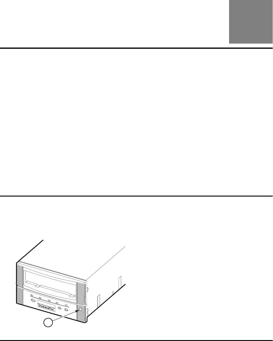
95741 Sixth Edition 8-1
8
Servicing the Drive
This chapter provides servicing information for the 9840 Tape Drive. It contains:
•“Jammed Cartridge”
•“Clean Tape Path” on page 8-3
•“Clean Fibre Channel Components” on page 8-4
•“Fibre Channel Loop Test” on page 8-8
■Jammed Cartridge
Note: Refer to Chapter 5, “Cartridge Scratch Loader” to remove a jammed
cartridge from a CSL.
A jammed cartridge in a 9840 Tape Drive is not a common malfunction.
However, you must know how to remove jammed cartridges when the
malfunction occurs.
Follow these instructions to remove a jammed cartridge from a drive.
1. Locate the MUD screw on the drive.
Note: The 9840 Tape Drive MUD screw is located on the right-front side of the drive (see
the figure below).
1. MUD screw
C5357
5
1
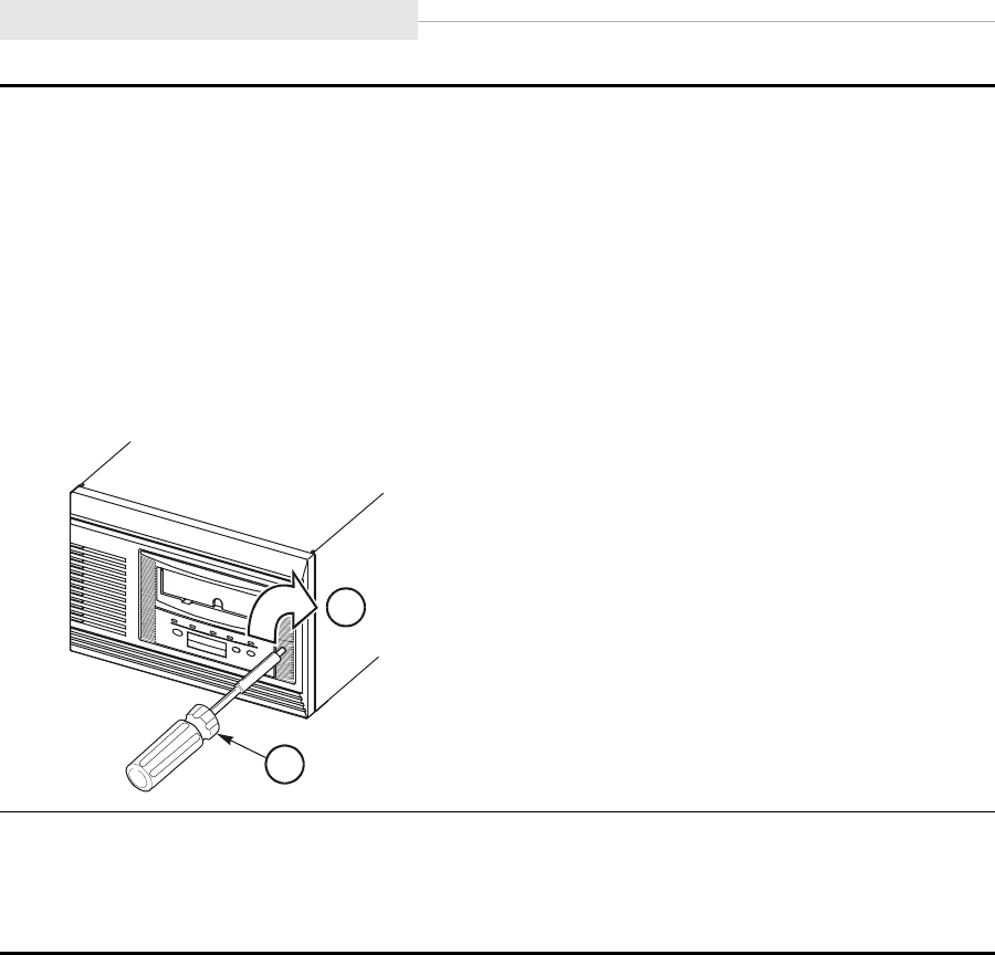
Jammed Cartridge
8-2 Sixth Edition 95741
2. Obtain a common screwdriver and insert it into the MUD slot.
3. Press against the spring-loaded MUD screw until it stops.
Note: Do not turn the screwdriver to the left or counter-clockwise (CCW) when
removing a jammed cartridge.
4. Slowly turn the screwdriver to the right or clockwise (CW) to remove the jammed
cartridge.
Note: When the MUD screw will not turn any further CW, the reel motors are lowered and
the cartridge can be removed.
1. Turn MUD screw clockwise
2. Screwdriver
5. Remove the screwdriver.
6. Remove the cartridge from the 9840 Tape Drive.
Note: If cartridges continue to jam, the drive is defective and must be replaced.
C53556
2
1

95741 Sixth Edition 8-3
Clean Tape Path
■Clean Tape Path
You clean the 9840 tape path with a cleaning cartridge. Clean the tape path
when the amber clean indicator illuminates. This indicator lights when certain
tape errors are detected or a certain length of tape moved through the tape
path.
CAUTION:
Do not wet-clean the 9840 tape path: no chemical cleaning is allowed.
Cleaning with chemicals or with tools other than the cleaning cartridge
is not allowed.
Note: This procedure does not require you to take the drive offline.
1. If applicable, unload the drive
2. Insert a cleaning cartridge into the drive
Note: If the cleaning cartridge ejects immediately without performing a clean
operation and the drive displays Exp CLcart, it means that the
cleaning tape is used up; obtain a new cleaning cartridge.
3. Observe the indications:
a. The green activity indicator flashes to indicate cleaning is taking place.
b. The cartridge ejects and the clean indicator turns off when cleaning is
complete.
Note: A displayed CHK xxxx message means a cleaning cartridge failure,
where xxxx is a fault symptom code; try a different cleaning
cartridge.
4. Remove the cleaning cartridge when the drive ejects the cartridge.
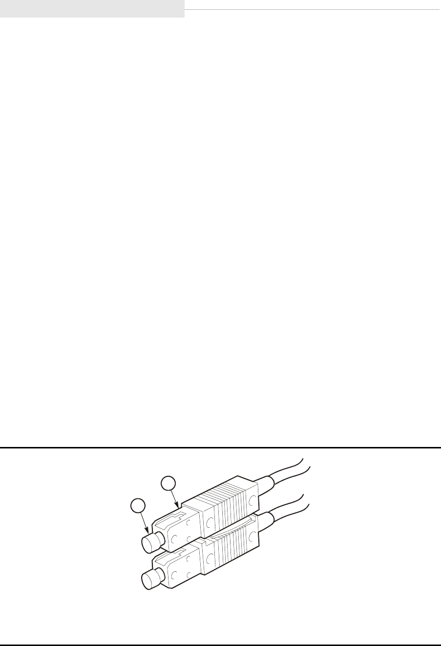
Clean Fibre Channel Components
8-4 Sixth Edition 95741
■Clean Fibre Channel Components
The following information describes a cleaning process for fibre channel
components such as connectors, GBICs, and plugs.
Fibre Channel Transmission
The 9840 Tape Drive uses a laser multi-mode transmitter-receiver (transceiver)
module. There are several warnings which everyone must know and
understand for their personal safety.
Note: Ensure you follow the instructions on “Fiber Optic Safety” in Chapter 2,
“Safety and Handling,” and the warnings listed in this section.
Cleaning Materials
Use the following list of materials to clean fibre-optic components:
•Alcohol pads
•Cloth pads
•Texwipe microswab
•Texwipe foam swab
Fibre Channel Cable
To clean a fibre channel cable (such as the one in Figure 8-1):
1. Blow any dust from the ferrule and the end of the connector using
compressed air by positioning the air nozzle approximately 50 mm (2 in.)
away from the connector and blowing for 5 seconds.
.
Figure 8-1. Fibre Channel Connector
1. Fibre Channel Cable Dust Covers
2. Fibre Channel Cable Housing
C53527
1
2
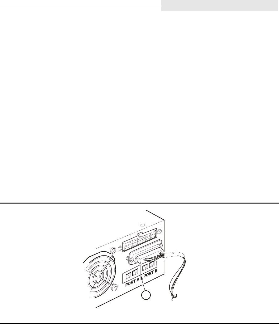
95741 Sixth Edition 8-5
Clean Fibre Channel Components
2. Gently wipe the ferrule and the end surface of the connector with an
alcohol pad. Ensure that the pad makes full contact with the end surface.
3. Wait 5 seconds for the surface to dry.
4. Repeat Step 1.
5. Wipe the ferrule and the end surface of the connector using a clean surface
of the alcohol pad.
6. Wait 5 seconds for the surface to dry.
7. Repeat Step 1 for final cleaning.
9840 Fibre Channel Drive Ports
To clean the drive ports (such as the one in Figure 8-2):
1. Remove the Fibre Channel cables to gain access to Ports A and B.
2. Blow any dust from the ferrule and the end of the port using compressed
air by positioning the air nozzle approximately 50 mm (2 in.) away from the
connector and blowing for 5 seconds.
3. Gently wipe the ferrule and the end surface of the port with an alcohol pad.
Ensure that the pad makes full contact with the end surface.
4. Wait 5 seconds for the surface to dry.
5. Repeat Step 2.
6. Wipe the ferrule and the end surface of the port using a clean surface of the
alcohol pad.
7. Wait 5 seconds for the surface to dry.
8. Repeat Step 2.
Figure 8-2. 9840 Fibre Channel Drive Ports
1. Fibre Channel Ports
E5352
8
1
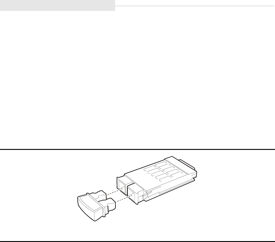
Clean Fibre Channel Components
8-6 Sixth Edition 95741
Fibre Channel GBIC
To clean a GBIC (giga-bit interface converter), refer to Figure 8-3).
Note: If GBICs are shipped or stored without a dust cover, clean the
connectors before installing into a Fibre Channel environment.
1. Blow any dust from the ferrule and the ends of the GBIC using compressed
air by positioning the air nozzle approximately 50 mm (2 in.) away from the
connector and blowing for 5 seconds.
2. Clean inside the GBIC with a swab saturated with isopropyl alcohol if
necessary.
3. Repeat Step 1.
Figure 8-3. Fibre Channel GBIC
C53529
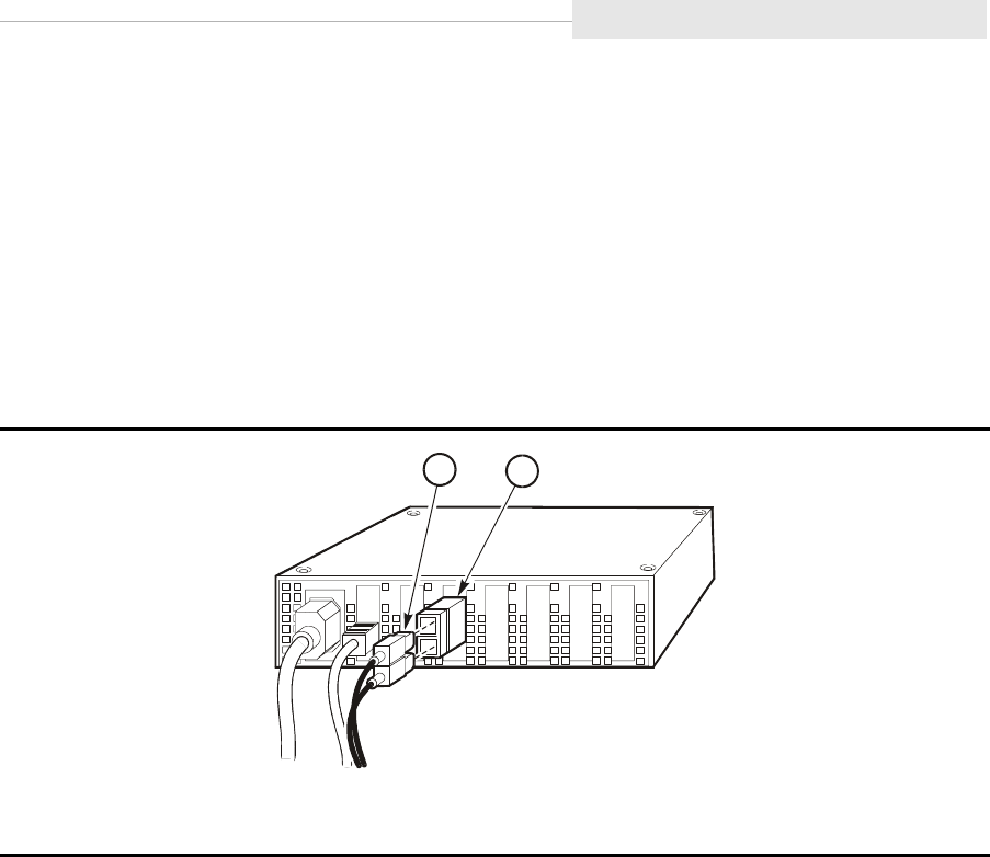
95741 Sixth Edition 8-7
Clean Fibre Channel Components
Fibre Channel Hub Slot
To clean a Fibre Channel hub slot, refer to Figure 8-4):
Before cleaning any Fibre Channel hub slot, notify the customer of the exact
hub and slot(s) that require cleaning. Customers may have a maintenance
contract with another vendor to maintain hubs and other devices on the
network.
Note: Ensure no I/O is present at the applicable hub slot.
1. Remove the applicable Fibre Channel cable and clean if necessary. Ensure
you follow the specified cleaning procedures in this section.
2. Remove the GBIC from the applicable slot and clean if necessary. Ensure
you follow the specified cleaning procedures in this section.
3. Blow any dust from the Fibre Channel cable ferrule using compressed air by
positioning the air nozzle approximately 50 mm (2 in.) away from the
connector and blowing for 5 seconds.
4. Clean inside the slot with a swab saturated with isopropyl alcohol if
necessary.
5. Repeat Step 2.
Figure 8-4. Fibre Channel Hub
1. Fibre Channel Cable
2. Fibre Channel GBIC
C53530
2
1

Fibre Channel Loop Test
8-8 Sixth Edition 95741
■Fibre Channel Loop Test
When you suspect Fibre Channel interface problems, you can conduct a fibre
channel loop test to check the drive’s optical ports as “alive or dead”. This test
will isolate the interface problem to the drive, or to the interface.
Tools Required for the Fibre Channel Loop Test
• Dual SC multi-mode fiber cable
Fibre Channel Loop Test Instructions
1. Take the drive offline to all hosts.
2. Disconnect the Fibre Channel interface cable at the drive end.
3. Connected a known good SC multi-mode fiber cable from Port A to Port B
on the drive.
Note: The ports should see each other and then arbitrate a loop address for
each port.
4. Place drive Online and navigate to the View Cfg ? menu.
5. Press Select to enter View submenus, then navigate to View PrtA?
submenu.
6. Press Select to enter View submenus, then navigate to A_I=xxyyzz
submenu.
Notes:
1. If the drive is operational, the current arbitrated loop address for
Port A will be displayed.
2. If Hard PA was Yes, the loop address will equal the Hard PA.
3. If Hard PA was No, the loop address will vary, typically:
A_I=000001 for Port A and A_I=000002 for Port B.
4. If A_I=...... is displayed, the drive is defective.
(Port A or Port B is not functioning properly; however, this test will
not determine which port is defective.)
7. Disconnect the fiber cable loop from Port A and Port B.
8. If loop test failed, replace drive.
9. If loop test was good, replace interface fiber cable.
Note: If replacing interface fiber cable does not solve the interface problem,
the fault is within the host system components.

95741 Sixth Edition A-1
A
Specifications
This appendix provides specifications for the 9840 Tape Drive. It contains:
•“Power Requirements”
•“Site Power Connector Requirements” on page A-2
•“Environmental Requirements” on page A-3
•“Cartridge Tape Specifications” on page A-5
•“Drive Performance” on page A-6
•“Host Interfaces” on page A-7
•“Library Attachments” on page A-7
•“Non-Library Drive Installations” on page A-8
•“Supported Device Modes” on page A-8
•“Host Hardware and Software Attachments” on page A-8
■Power Requirements
The specifications shown in Table A-1 reflect power requirements for each 9840
Tape Drive installed as a desktop and rack-mount drive tray.
Table A-1. Power Requirements
Characteristics Value
Input voltage 100 to 240 VAC
Input frequency 50 to 60 Hz
Power consumption 101 VA
Power dissipation 345 Btu/hr
Power factor 0.95 minimum

Site Power Connector Requirements
A-2 Sixth Edition 95741
■Site Power Connector Requirements
The power drop connections are described here only for the stand-alone rack
and the desktop drives. In all other cases the drives plug into power strips in
the StorageTek equipment.
Table A-2. Site Power Drop Connectors
Where Used STK Cable
Part Number
STK
Feature
Connector
Description
Plug/Receptacle
identification1
Desktop/Rack
North America
(Canada, U.S)
10083242 9930 Household type,
3-prong 120 VAC
10 A
NEMA-5-15P (M)
NEMA-5-15R (F)
Desktop/Rack
North America
(Canada, U.S)
10083625 9930 Household type,
3-prong 120 VAC
15 A
NEMA-5-15P (M)
NEMA-5-15R (F)
Rack Domestic 3127950-xx 9953 Hubbell type 250
VAC 15 A (IEC309)
Hubbell
320P6W (M)2
Rack Domestic 3127949-xx 9952 Russellstoll type
250 VAC 15 A
Russellstoll
3720DP (M)3
Desktop
Export
10083241 9931 Continental4 Europe
standard 250 VAC
10 A
CEE7-75 (SCHUKO)
plug or receptacle
Rack
Export
10083302 9954 Comes without
client-side connector
10 A cable
Connectors
supplied by client
Notes:
1. The female (F) receptacle is identified for information only: it is supplied by the
client.
2. This male (M) connector is compatible with inline female connector Hubbell
320C6W and wall receptacle Hubbell 320R6W or inline female connector
RS320C6W and wall receptacle RS320R6W.
3. This male (M) connector is compatible with Russellstoll inline female connector
RS3913 and wall receptacle RS3743.
4. Standardized in Belgium, Finland, France, Germany, Holland, Norway, and
Sweden.
5. Order this cable for all desktop installations outside North America. If the
attached client-side connector cannot be used, remove it and replace with client’s
choice.

95741 Sixth Edition A-3
Environmental Requirements
■Environmental Requirements
This section describes environmental requirements, including the drive, power
supply, cartridge tapes, and media for the 9840 Tape Drive.
Drive and Power Supply
Table A-3 shows the environmental requirements for the drive and the power
supply for the 9840 Tape Drive.
Table A-3. Drive and Power Supply Requirements
Temperature
Operating 15º to 32ºC (59º to 90ºF)
Storage 10º to 40ºC (50º to 104ºF)
Shipping -40º to 60ºC (-40º to 140ºF)
Relative Humidity Non-Condensing
Operating 20% to 80%
Storage 10% to 95%
Shipping 10% to 95%
Wet Bulb Maximum
Operating 26ºC (79ºF)
Storage 26ºC (79ºF)
Shipping 26ºC (79ºF)
Altitude
Operating Up to 3.05 km (up to 10,000 ft)
Storage Up to 3.05 km (up to 10,000 ft)
Shipping Up to 15.24 km (up to 50,000 ft)
Operating Heat Output/Air Flow Requirements
Drive and power
supply
61.7 kCal (241.3 Btu/hr)

Environmental Requirements
A-4 Sixth Edition 95741
Cartridge Tapes and Media
Table A-4 shows the environmental requirements for cartridge tapes and media
for the 9840 Tape Drive.
Table A-4. Cartridge Tapes and Media Requirements
Temperature
Operating (see note) 15º to 32ºC (59º to 90ºF)
Storage (up to four weeks) 5º to 32ºC (41º to 90ºF)
Storage (archive) 18º to 26ºC (65º to 79ºF)
Shipping -23º to 49ºC (-10º to 120ºF)
Relative Humidity, Non-Condensing
Operating (see note) 20% to 80%
Storage (up to four weeks) 5% to 80%
Storage (archive) 40% to 60%
Shipping 5% to 80%
Wet Bulb Maximum
Operating (see note) 26ºC (79ºF)
Storage (up to four weeks) 26ºC (79ºF)
Storage (archive) 26ºC (79ºF)
Shipping 26ºC (79ºF)
Note: Allow a cartridge to acclimatize within the operating environment for
at least 24 hours.

95741 Sixth Edition A-5
Cartridge Tape Specifications
■Cartridge Tape Specifications
Table A-5 shows the specifications for the cartridge tapes to be inserted into the
9840 Tape Drive.
CAUTION:
Do not degauss 9840 Tape Drive cartridges. Servo tracks are written on
the tape at the factory. When these tracks are mistakenly erased, the
cartridge tape must be discarded.
Table A-5. Cartridge Tape Specifications
Characteristics Values
Type STK1R data cartridge,
StorageTek PN 310319401
271 m (889 ft) physical length
251 m (823 ft) recordable length
9 µm tape thickness
288 tracks
Advanced metal particle
Type STK1U cleaning cartridge,
StorageTek PN 310324601
Good for about 100 cleanings. Estimated
usage: 1 cleaning per drive every two days.
Dimensions 125 x 109 x 25.9 mm
(4.92 x 4.29 x 1.00 in.)
Data Compression LZ-1 Enhanced, 4:1 Ratio
Note: Individual results may vary depending on the characteristics of the
data and other variables.
Capacity 20 GB uncompressed
Archival Life 15 to 30 years
Media Durability
Short length
Long length
80,000 write/read passes minimum
6,500 write/read passes minimum
Load/Unloads 10,000 minimum
Uncorrected bit error rate,
including those caused by
media defects
1 in 1018 bytes
Permanent Errors Zero
Weight 0.26 kg (9.17 oz)

Drive Performance
A-6 Sixth Edition 95741
■Drive Performance
Table A-6 shows performance characteristics of the 9840 Tape Drive.
Table A-6. Drive Performance
Characteristics Values
Maximum block size 256 kB
Data rate, head-to-tape 10 MB/s (see note)
Data rate of host interface Fibre Channel: burst transmission speed of
100 MB/s (256 kB)
Ultra SCSI: 40 MB/s burst synchronous/
ULTRA-1, differential, wide/fast, negotiable
down to SCSI-1 narrow differential (see note)
Maximum rewind time:
from end of any wrap to
logical beginning of tape
(BOT)
16 s
Reposition time No penalty
Tape load and initialize to
ready
4 s
Unload time 5 s excluding rewind
Access time (does not
include library timing)
8 s for first search
11 s average for subsequent search
Data buffer size 8 MB
Read/write speed 2m/s (79 ips)
Search/rewind speed 8 m/s (315 ips)
Note: Individual results may vary depending on the characteristics of the
data and other variables.

95741 Sixth Edition A-7
Host Interfaces
■Host Interfaces
Table A-7 provides the 9840 Tape Drive host interfaces. The 9840 Tape Drive is
used in Fibre Channel and SCSI environments.
■Library Attachments
Table A-8 provides the library attachment.
Table A-7. Host Interfaces
Interface Type Interface Characteristics
Fibre Channel Transmission speed of 100 MB/s (burst)
Interface options:
•Bridge: Connects SCSI devices to an
FC network
•Hub: Connects FC devices in a logical
loop
•Switch: Connects FC devices in a
fabric
SCSI Synchronous, differential (burst):
•Narrow/slow at 5 MB/s
•Narrow/fast at 10 MB/s
•Narrow/ultra at 20 MB/s
•Wide/slow at 10 MB/s
•Wide/fast at 20 MB/s
•Wide/ultra at 40 MB/s
Table A-8. Library Attachments
Library Type Description
9738 A StorageTek TimberWolf family library. It holds 30
cartridges and up to 3 drives. Fibre Channel and SCSI
interfaces are supported.

Non-Library Drive Installations
A-8 Sixth Edition 95741
■Non-Library Drive Installations
Table A-9 provides a list of non-library drive installations. The 9840 Tape Drive
ships as a desktop or rack unit within this environment.
■Supported Device Modes
Table A-10 provides the supported device modes.
■Host Hardware and Software Attachments
The 9840 Tape Drive compatibilities expand frequently. Ask your local
StorageTek sales representative for the latest information.
Table A-9. Non-Library Drive Installations
Installation Type Description
Desktop, manual-load This installation consists of a 9840 Tape Drive
and a power supply. The desktop has the
smallest footprint of any version of the 9840.
Fibre Channel and SCSI interfaces are
available for the 9840.
Desktop, CSL This installation consists of a 9840 Tape
Drive, a CSL mechanism, and a power
supply. Fibre Channel and SCSI interfaces are
available for the 9840.
Rack-mountable, manual-load This installation consists of a rack-mount tray
with either one drive and power supply, or
two drives side-by-side and two power
supplies. The StorageTek rack holds up to six
trays. Fibre Channel and SCSI interfaces are
available for the 9840.
Rack-mountable, CSL This installation consists of a rack-mount tray
with one 9840 Tape Drive, a CSL mechanism,
and a power supply. The StorageTek rack
holds up to six trays. Fibre Channel and SCSI
interfaces are available for the 9840.
Table A-10. Supported Device Modes
Interface Type 9840 Native 3490E Emulation
(AS400 only)
3590B Emulation
(AS400 only)
Fibre Channel Yes No Yes
SCSI Yes Yes Yes

95741 Sixth Edition Glossary-1
Glossary
This glossary defines abbreviations and new
or special terms used in this publication.
Some of the definitions are taken from the
IBM Dictionary of Computing. The letters in
parentheses that follow some definitions
indicate the source of the definition:
(A) The American National Standard
Dictionary for Information Systems, ANSI
X3.172-1990, copyright 1990 by the American
National Standards Institute (ANSI).
(E) The ANSI/Electronic Industries
Association (EIA) Standard-440-A, Fiber Optic
Terminology.
(I) The Information Technology Vocabulary,
developed by Subcommittee 1, Joint
Technical Committee 1, of the International
Organization for Standardization and
International Electrotechnical Commission
(ISO/IEC/JTC1/SC1).
(IBM) The IBM Dictionary of Computing,
copyright 1994 by IBM.
(T) Draft international standards committee
drafts, and working papers being developed
by the ISO/IEC/JTC1/SC1.
A
access time The time interval between the
instant at which a call for data is initialized
and the instant at which the delivery of data
is completed. (T)
adapter Hardware used to join different
optical fiber connector types. (IBM)
address A character or group of characters
that identifies a register, a particular part of
storage, or some other data source or
destination. (A)
AL_PA See Arbitrated Loop Physical Address.
alphanumeric Pertaining to data that
consist of letters, digits, and usually other
characters, such as punctuation marks. (T)
(A)
Arbitrated Loop A topology in Fibre
Channel that provides multiple connections
for devices that share a single loop, over
which only two devices can communicate at
once. Similar to the SCSI protocol of the same
name, it provides an “arbitrate and win”
scenario among more than two devices when
those devices want to communicate on the
bus. The sending device must arbitrate and
win the connection with the receiving device
before communication can begin.
Arbitrated Loop Physical Address A one-
byte value that identifies a port in an
arbitrated loop topology.
ASIA Application specific interface adapter.
The interface card in the 9840 Tape Drive.
B
beginning-of-tape A point on the tape
where written data begins.
bin See Cartridge Scratch Loader (CSL)
block A string of data elements recorded or
transmitted as a unit. The elements may be
characters, words, or physical records. (T)
British thermal unit (Btu) A standard
measure of a device’s heat output. The
amount of heat required to raise one pound
of water one degree Fahrenheit.
Btu See British thermal unit.
buffer A routine or storage used to
compensate for a difference in rate of flow of
data, or time of occurrence of events, when
transferring data from one device to another.
(A)

Glossary-2 Sixth Edition 95741
Glossary
burst In data communication, a sequence of
signals counted as one unit in accordance
with some specific criterion or measure. (A)
C
cartridge A storage device that consists of
magnetic tape on supply and takeup reels, in
a protective housing. (IBM)
Cartridge Scratch Loader (CSL) In the
9840 Tape Drive, a device attached to the
9840 drive which automatically feeds
cartridges to the drive. Cartridges are
manually placed in an input bin, and after
use, are deposited automatically in an output
bin.
channel A functional unit, controlled by the
processor (or host), that handles the transfer
of data between processor storage and local
peripheral equipment. (IBM)
check A detection of an error condition or
test for correct condition.
CHK Check.
checksum In error detection, a function of
all bits in a block. If the written and
calculated sums do not agree, an error is
indicated. (IBM)
cleaning cartridge A cartridge tape
containing special material used to clean the
tape path in a transport.
compress To save storage space by
eliminating gaps, empty fields, redundancy,
or unnecessary data to shorten the length of
records or files. (IBM)
configuration The manner in which the
hardware and software of an information
processing system are organized and
interconnected. (T)
configuration error An error that results
from incorrect configuration values.
connector An electrical part used to join
two or more other electrical parts. (IBM)
CSL See Cartridge Scratch Loader.
CSL operator panel A combination of the
9840 Tape Drive operator panel controls with
additional switches and indicators for the
Cartridge Scratch Loader.
D
data rate The speed of a data transfer
process, normally expressed in bits per
second or bytes per second. (IBM)
Data Security Erase (DSE) . A random
binary pattern, over-writing existing data,
from the point of an “Erase” command, to the
End of Tape point.
data tape A tape cartridge formatted for use
as a regular data tape for the system in which
it is used.
diagnostic Pertaining to the detection and
isolation of errors in programs and faults in
equipment. (IBM)
differential A SCSI bus alternative that
provides better signal quality with less
crosstalk and noise but requires more power
to drive the signal. The maximum cable
length is 25 m (82 ft).
drive A device for moving magnetic tape
and controlling its movement. (IBM)
DSE See data security erase.
dump To copy the contents of all or part of
virtual storage for the purpose of collecting
error information. (IBM)
dump-formatted cartridge A cartridge on
which the tape has been specially formatted
to store diagnostic dump data.
E
emulation The use of programming
techniques and special machine features to
permit a computing system to execute
programs written for another system. (IBM)

95741 Sixth Edition Glossary-3
Glossary
enterprise A representation of the goals,
organizational structure, business processes,
and information resources and requirements
of an enterprise. (IBM)
environmental requirement Any of the
physical conditions required for the
protection and proper operation of a
functional unit; the requirement is usually
specified as a nominal value and a tolerance
range. For a device, there may be more than
one set of environmental requirements; for
example, one set for transport, another for
storage, and another for operation. (T) (A)
error A discrepancy between a computed,
observed, or measured value or condition
and the true, specified, or theoretically
correct value or condition. (I) (A)
F
F_Port A Port within the Fabric which
attaches to an N_Port through a link.
fabric The FC topology that is similar to a
telephone switch in that the initiator of a
“call” to the receiving port simply provides
the receiver with the port address, and the
fabric routes the transmission to the proper
port. A fabric differs from a point-to-point or
arbitrated loop topology in that it provides
for interconnections between ports without
having a point-to-point connection. The
fabric also serves as a media type converter.
fault symptom code (FSC) A hexadecimal
code generated by the drive for controller
microcode in response to a detected
subsystem error.
FC See Fibre Channel.
fibre channel (FC) The ANSI standard that
defines an ultra high-speed, content
independent, multi-level data transmission
interface that can support multiple protocols
simultaneously, support connectivity to
millions of devices over copper and/or fiber
optic physical media, and provides the best
characteristics of both networks and
channels, over diverse topologies.
field replaceable unit (FRU) An assembly
that is replaced in its entirety when any one
of its components fails. (IBM)
file-protect To prevent the destruction or
overwriting of data stored on cartridge tape.
See also write-protect switch.
firmware An ordered set of instructions and
data stored in a way that is functionally
independent of main storage; for example,
microprograms stored in a ROM. (T)
FL_Port An F_Port within the Fabric which
also contains the Loop Port State Machine as
defined in FC-AL-2. The FL_Port attaches to
an NL_Port through a link.
FRU See field replaceable unit.
FSC See Fault Symptom Code.
G
GB See Gigabyte.
Gb Gigabit, equal to 109 bits.
GBIC See Gigabit Interface Converter
gigabit (Gb) One billion (109) bits.
Gigabit Interface Converter (GBIC) An
adapter that connects a fiber-optic or copper-
wire cable to a Fibre Channel hub or switch.
gigabyte (GB) One billion (109) bytes.
When referring to memory capacity,
1,073,741,824 in decimal notation. (IBM)
H
hardware All or part of the physical
components of an information processing
system, such as computers or peripheral
devices. (T) (A)
HBA See host bus adaptor

Glossary-4 Sixth Edition 95741
Glossary
host The primary computer on a network,
with which other computers interact.
host bus adapter (HBA) A circuit installed
in a multi-platform host or device that
interfaces between the device and the bus.
host interface Interface between a network
and host computer. (T)
hub A piece of hardware, separate from the
actual FC interface accessible on the
backplane of a device, which houses the port
bypass circuitry for configurations of 8 to 16
ports per hub. Hubs may be cascaded to
support larger configurations, and can usually
support a mix of both electrical and optical
media ports in the same hub.
I
indicator A device that gives a visual or
other indication of the existence of a defined
state. (T)
initialization The operations required for
setting a device to a starting state, before the
use of a data medium, or before
implementation of a process. (T)
Initial Program Load (IPL) The
initialization procedure that causes an
operating system to commence operation.
input/output (I/O) Pertaining to a device,
process, or channel involved in data input,
data output, or both. (IBM)
interface Hardware, software, or both, that
links systems, programs, or devices. (IBM)
I/O See input /output.
IPL See Initial Program Load.
L
laser A term meaning Light Amplification by
Stimulated Emission of Radiation. Laser
devices generate coherent radiation in the
visible, ultraviolet, and infrared portions of
the electromagnetic spectrum. Regarding FC,
lasers can be transmitting either short waves
or long waves, depending on the
composition of the arbitrated loop or fabric.
library installation The process of
installing the 9840 Tape Drive in a library
environment.
link A two-fiber connection made between
two FC ports in which one fiber is
transmitting, the other receiving, information.
logical device address A number used to
represent a terminal or terminal component
within a workstation. (IBM)
M
magnetic tape A tape with a magnetizable
layer on which data can be stored. (T)
manual operation Processing of data in a
system by direct manual techniques. (IBM)
MB Megabytes, or 1,048,576 bytes.
media defects Physical impurities or other
problems that cause the medium to function
improperly.
medium A physical material in or on which
data may be represented. (IBM)
menu A list of options displayed to the user
by a data processing system, from which the
user can select an action to be initiated. (T)
microcode A code, representing the
instructions of an instruction set, that is
implemented in a part of storage that is not
program-addressable. (IBM)
N
N_Port A Port within the Node that attaches
to a link.
network An arrangement of nodes and
branches, connecting data processing devices

95741 Sixth Edition Glossary-5
Glossary
to one another via software and hardware
links, to facilitate information interchange.
NL_Port An N_Port within the Node which
also contains the Loop Port State Machine as
defined in FC-AL-2. The NL_Port attaches to
either an FL_Port or an NL_Port through a
link.
node A device that contains a minimum of
one N_Port and/or NL_Port.
O
offline Neither controlled by, nor
communicating with, a computer. (IBM)
online Pertaining to the operation of a
functional unit when under the direct control
of the computer. (T)
operating system Software that controls
program execution.
operator control panel A functional unit
that contains switches used to control all or
part of a computer and possibly the
indicators giving information about its
functioning. (T)
P
performance One of two major factors,
together with facility, on which the total
productivity of a system depends.
Performance is largely determined by a
combination of throughput, response time,
and availability. (IBM)
point-to-point A topology in which exactly
two ports communicate. In FC, the two ports
are N_Ports.
port A specific communications end point
within a host. A port is identified by a port
number. (IBM) In FC, it is an access point in
a device where a link attaches. Examples of
this port are N_Port, NL_Port, F_Port, and
FL_Port.
private loop An Arbitrated Loop that does
not contain a participating FL_Port but does
contain two or more NL_Ports.
Private NL_Port An NL_Port that does not
attempt a Fabric Login.
protocol A set of semantic and syntactic
rules that determines the behavior of
functional units in achieving communication.
(I).
public loop An Arbitrated Loop that
includes a participating FL_Port and at least
one NL_Port.
Public NL_Port An NL_Port that attempts a
Fabric Login.
R
random access memory (RAM) A storage
device in which data can be written and read.
(IBM).
read/write head The data sensing and
recording unit of a diskette magazine drive or
tape drive. (IBM)
reclaim The process of reformatting a tape
as a data tape.
release A distribution of a new product or
new function and fixes for an existing
product. (IBM)
restore To return a backup copy to the
active storage location for use. (IBM)
rewind To move tape from the take-up hub
to the supply hub. (IBM)
S
SCSI See small computer system interface.
small computer system interface (SCSI)
An input and output bus that provides a
standard interface between the OS/2
multimedia system and peripheral devices.
(IBM)

Glossary-6 Sixth Edition 95741
Glossary
software All or part of the programs,
procedures, rules, and associated
documentation of a data processing system.
Software is an intellectual creation that is
independent of the medium on which it is
recorded. (T)
state The condition of a device, such as
online or offline.
sub-menu A menu related to and reached
from a main menu. (IBM)
switch A device or programming technique
for making a selection; for example, a toggle,
a conditional jump. (A)
T
tape See magnetic tape.
tape drive A device for moving magnetic
tape and controlling its movement. (T)
target A SCSI device performing an I/O
operation requested by the initiator.
topology A method or scheme for
connecting ports for communicating in FC.
FC topologies include Point-to-Point,
Arbitrated Loop, and Fabric.
V
VolSafe A mode of operation and special
data cartridge tape that allows data only to be
appended to the cartridge tape; no data is
overwritten.
VOLSER A six-character alphanumeric label
used to identify a volume.
W
write operation An output operation that
sends a processed record to an output device
or output file. (IBM)
write protection Restriction of writing into
a data set, file or storage area of a user or
program not authorized to do so. (IBM)

95741 Sixth Edition Index-1
Index
Symbols
* (asterisk) display, 7-3
*Cleaning* display, 7-4
Numerics
9738
apply power to library drive, 3-18
cleaning cartridge, 3-18
daisy-chain 9840, 3-17
drive slot positions, 3-10
features, 1-6
information, A-7
install 9840 power supply, 3-11
install procedures, 3-8
interface, 3-1
library, 1-6
overview, 3-1
SCSI interface, 3-13
term power, 3-16
TTI cable, 3-13
A
access time, A-6
activity indicator, 1-11, 4-5
address setting
fibre channel
hard, 6-14
soft, 6-14
SCSI ID, 6-27
alphabetic list-error codes, 7-3
amber clean indicator, 8-3
Application Specific Interface Adaptor
(ASIA), 7-9
AS400 SCSI cables (p/ns), 3-5
ASIA
checksum test, 7-10
explanation, 7-9
ASIA DIAGS display, 4-2, 7-3
attachments, hardware, A-8
autoload mode switch, 5-8, 5-9
automatic
indicator, 5-8, 5-11
mode, 5-18, 5-21
B
bad
EEPROM, 7-4
RAM, 7-6
Bank n Bad display, 7-3
bin
input, 5-2
output, 5-2
Boot Fail display, 4-2, 7-3
BT Monitor, 7-3
BT Monitor display, 7-3
buffer size, A-6
build MIR, 6-38
bus speed
Fibre Channel, A-7
SCSI, 6-28
bus width, SCSI, 6-28
C
cable
installation
9738 Fibre Channel interface, 3-13
9738 SCSI interface, 3-16
desktop, fibre channel, 3-21
desktop, SCSI, 3-23, 3-49
rack-mount, fibre channel, 3-46
rack-mount, SCSI, 3-49
part numbers
fibre channel, 3-4
SCSI, 3-5
captive nuts, 3-30, 3-32
cartridge
failure to load, 5-24
formatting, 4-9
jammed in CSL, 5-30
jammed in drive, 8-1
load, 4-7

Index-2 Sixth Edition 95741
Index
procedures, 5-14
reclaim, 4-9
removal from CSL, 5-30
routing, 5-3
scratch loader (CSL), 6-3
specifications, A-5
standard, 1-16
stop mechanism, 5-20
unload from CSL, 5-15
VolSafe, 1-16
write protect, 4-6
cartridge scratch loader
rack-mount installation, 3-39
shipping insert removal, 3-43
side panel installation, 3-43
cascading hubs, 3-6
caution, shielded cables, xix
CC DIAG display, 4-2, 7-3
change SCSI configuration, 6-24
channel
feed for CSL, 5-2
fibre channel transmission, 8-4
setting
SCSI narrow, 6-27
SCSI wide, 6-27
transfer rate
fibre channel, A-6
SCSI, A-6
Channels web site, xviii
characteristics of drive, 1-1
chart
main menu operation, 6-3
chart online
View CFG? menu, 6-5
checksum, 7-9
CHK xxxx, 8-3
CHK xxxx (FSC) display, 7-4
Chng CFG?
fibre channel, 6-13
SCSI, 6-26
Clean indicator, 4-5
cleaning
cables, 8-5
cartridge, 4-5
complete indication, 8-3
fiber optic
kit, 8-4
materials needed, 8-4
fibre channel
components, 8-4
GBIC, 8-6
hub slot, 8-7
fibre channel cable, 8-4
indicator, 1-12
illumination, 8-3
process complete, 4-5
tape path, 8-3
cleaning cartridge, use in 9738, 3-18
clear
operator indicator error, 5-27
cnhndnsn display, 7-3
CodCrFail1, 7-4
CodCrFail1 display, 7-4
CodCrFail2 display, 7-4
code FSCs, 5-23
CodeUpDate display, 7-4
CodUpFail1 display, 7-4
CodUpFail2 display, 7-4
CodUpFail3 display, 7-5
CodUpFail4 display, 7-5
collect diagnostic dump, 4-11
comments on this manual, xvi
compatibilities of 9840, A-8
compliance statements
code, xxi
FCC, xix
Japanese, xx
Taiwan, xx
compression
fibre channel, 6-14
SCSI, 6-26
configuration
CSL, 1-4
drive menu
code update, 6-36
create code tape, 6-37
dump tape, 6-36
main display, 6-35
reclaim a tape, 6-37
Servo Head Diagnostic, 6-39
Servo Load/Unload Diagnostic, 6-40
W/R Diagnostic, 6-39
fibre channel
compression, 6-14, 6-26
CSL modes, 6-20
DSE, 6-14

95741 Sixth Edition Index-3
Index
emulation, 6-18
frame sizes, 6-16
hard physical address, 6-14
language, 6-17
library address, 6-20
port attributes, 6-14
soft physical address, 6-15
tape bar, 6-17
VolSafe, 6-18
incorrect data, 7-10
menu
offline, 6-7
online, 6-5
SCSI
bus width, 6-28
CSL modes, 6-31
DSE, 6-27
emulation, 6-19, 6-29, 6-30
ID address, 6-27
language, 6-28
library address, 6-31
speed (ultra/fast/slow), 6-28
tape bar, 6-28
VolSafe, 6-29
status
fibre channel, 6-9
SCSI, 6-23
configurations, 1-2
connector
fibre channel, 3-4
for drop power, A-2
SCSI, 3-5
copyright statement, ii
CSL
capacity, A-8
cartridge
procedures, 5-14
routing, 5-3
stop mechanism, 5-20
unloading, 5-15
components,5-2,5-5
CSL NONE message, 6-3
desktop
description, 5-5
dimensions, 5-5
drive, 1-4
fault symptom codes (FSCs), 5-23
feed channel, 5-2
FRUs, 1-4
FSCs, 5-28
host interfaces, 5-2
indicators
automatic, 5-11
location, 5-10
manual, 5-11
operator, 5-11
system, 5-11
information, 6-3
input bin, 5-2
installation, 3-27
interfaces
desktop, 5-5
Fibre Channel, 5-2
SCSI, 5-2
malfunction
4eXX FSCs, 5-23
clear error, 5-23
modes
automatic, 5-18, 5-21
explanation, 5-16
manual, 5-19
priority, 5-20
system, 5-16, 5-20
operator
indicator, 5-23
panel, 5-2, 5-8
output bin, 5-2
overview, 1-4
power
explanation, 5-12
supply, 1-4
power on, 5-12
rack
components, 5-7
dimensions, 5-7
enclosure, 5-6
removing shipping insert, 3-20, 5-36
specifications, A-8
Customer Resource Center (CRC), xviii
D
daisy-chain in 9738, 3-17
damaged EEPROM, 7-11
data buffer size, A-6

Index-4 Sixth Edition 95741
Index
data transfer rate
fibre channel, A-6
SCSI, A-6
DatCrFail1 display, 7-5
defective
EEPROM, 7-9
RAM, 7-9, 7-10
description, 1-4
desktop
capacity, A-8
CSL features, 5-5
description, A-8
drop power, A-2
fibre channel cable, 3-21
installation, 3-19, A-8
interface, 3-1, A-8
fibre channel, 3-21
SCSI, 3-21
model, 1-3
non-library installation, A-8
overview, 3-1
power-on, 3-25
SCSI cable, 3-23, 3-49
term power, 3-23
device modes
fibre channel, A-8
SCSI, A-8
diagnostic dump tape, 4-10
dimensions
cartridge, A-5
desktop, 5-5
rack for CSL, 5-7
dislodging stuck tape, 7-2
display
* (asterisk), 7-3
*Cleaning*, 7-4
ASIA DIAG, 7-3
Bank n Bad, 7-3
Boot Fail, 7-3
BT Monitor, 7-3
CC DIAG, 7-3
CHK xxxx (FSC), 7-4
cnhndnsn, 7-3
CodCrFail1, 7-4
CodCrFail2, 7-4
CodeUpDate, 7-4
CodUpFail1, 7-4
CodUpFail2, 7-4
CodUpFail3, 7-5
CodUpFail4, 7-5
DatCrFail1, 7-5
DmpCrFail1, 7-5
DmpCrFail2, 7-5
DmpWrFail1, 7-5
DmpWrFail2, 7-5
DumpAgain?,7-5,7-12
DumpToHost, 7-5
Exp CLCart, 7-5
Fix_CfgErr, 7-6
INITxxxx (FSC), 7-6
IPL Pend, 7-6
Load CC, 7-6
Load Fibre Channel, 7-6
Load SCSI, 7-6
Load xxxx (FSC), 7-6
Loading, 7-6
Locating, 7-6
Memory Err, 7-6
NT Ready A, 7-6
NT Ready F, 7-6
NT Ready U, 7-7
Offline, 7-7
Online, 7-7
Power Fail, 7-7
Reading, 7-7
Ready A, 7-7
Ready F, 7-7
Rewinding, 7-7
Save Fails, 7-7
SavingDump, 7-8
Start Init, 7-8
Trapped, 7-8
Unloading, 7-8
UnWr xxxx (FSC), 7-8
Write Prot, 7-8
Writing, 7-8
xxxx Dmpyy, 7-6
display, tape drive operator panel, 1-14
DmpCrFail1 display, 7-5
DmpCrFail2 display, 7-5
DmpWrFail1 display, 7-5
DmpWrFail2 display, 7-5
drive, 1-11
9738 slot positions, 3-10
characteristics, 1-1
dry cleaning, 4-5

95741 Sixth Edition Index-5
Index
dry cleaning tape path, 8-3
host interface cable, 3-46
installation
desktop model, 3-19
non-library, A-8
rack, 3-28
operation
overview, 4-1
saves, 7-9
operations menu tree, 6-34
ports
A and B, 8-5
cleaning, 8-5
power
off CSL, 5-13
off drive, 4-2
on CSL, 5-12
power on drive, 4-1
rack-mount tray, 3-41
tray (rack), 3-40
view configuration, 4-4
wet cleaning, 4-5
drop connectors, A-2
dry clean
drive, 4-5
tape path, 8-3
DSE
FC setting, 6-14
SCSI setting, 6-27
DumpAgain? display, 7-5, 7-12
DumpToHost display, 7-5
E
EEPROM
bad, 7-4
checksum, 7-9
damaged, 7-11
defective, 7-9
dump data, 7-6
IPL no dump, 7-12
operation, 7-9
partial damage, 7-11
saving dump data, 7-8, 7-12
service light on, 7-12
emulation mode
fibre channel, 6-18
SCSI, 6-19, 6-30
enable
compression
fibre channel, 6-14
SCSI, 6-26
VolSafe
fibre channel, 6-18
SCSI, 6-29
enclosure rack, 5-6
environmental requirements, A-3
drive and power supply, A-3
tape cartridges and media, A-4
error
action to take, 7-2
caution, 7-10
CHK xxxx, 8-3
codes, 7-3
configuration, 7-9
Exp CLCart, 8-3
Fix_CfgErr, 7-9, 7-10, 7-11
Fix_CfgErr indication, 7-9
indications
CSL, 5-28
drive, 7-2
explanation, 7-9
operator indicator, 5-27
power, 7-1
RAM, 7-6, 7-11
save configuration, 7-9
Save Fails, 7-9, 7-11
service, 7-1
stuck tape, 7-2
unload, 7-12
ESD
grounding kit, contents, 2-3
precautions and practices, 2-3
procedures to follow when servicing, 2-3
example of menu, 6-4
Exit CFG ? message, 4-4
exit displays
Exit CFG?
fibre channel, 6-22
SCSI, 6-33
Exit Menu?
fibre channel, 6-22
SCSI, 6-33
Exp CLCart display, 7-5, 8-3
explanation
conventions, xvii

Index-6 Sixth Edition 95741
Index
FSCs, 5-23
notes, xvi
warning, xvi
F
failure
CSL (FSCs), 5-28
EEPROM, 7-4
to load, 5-24
fast SCSI, 6-28
fault symptom code (FSC), CSL, 5-28
features
of 9738, 1-6
of library, 1-6
feed channel, 5-2
fiber-optic
cables
connectors, 2-7
handling, 2-6
installation, 2-7
cleaning materials, 8-4
warnings, 2-5
fibre channel
cables
cleaning, 8-5
connector, 3-4
part numbers, 3-4
rack-mount, 3-46
Chng CFG?, 6-13
cleaning
drive ports, 8-5
GBICs, 8-6
hub slot, 8-7
components, 8-4
compression
CMPRSS No, 6-14
CMPRSS Off, 6-14
CMPRSS On, 6-14
setting, 6-14
CSL
auto mode, 6-20
manual mode, 6-20
system mode, 6-20
data rate, A-6
description, Glossary-3
device modes, A-8
DSE
no, 6-14, 6-27
yes, 6-14, 6-27
emulation mode, 6-18
Exit CFG?, 6-22
Exit Menu?, 6-22
interface
cable, 5-2
CSL, 5-2
description, 1-2
host channel, 5-2
language selection, 6-17, 6-28
library address, 6-20
logical paths, 5-2
loop test, 8-8
offline configuration, 6-13
physical address
hard setting, 6-14
soft setting, 6-14
port
attributes, 6-14, 6-27
enable, 6-13
Save CFG?, 6-22
Save Fails, 6-22
setting frame size, 6-16
speed, 5-2
submenus, 6-13
topology
private loop, 6-14, 6-27
public loop, 6-14, 6-27
transmission, 8-4
VolSafe, 6-18
Fibre Channel cable
9738 library, 3-13
desktop, 3-21
rack-mount, 3-46
Fibre Channel Loop Test, 8-8
Fix_CfgErr
display, 7-6
error indications, 7-9
explanation, 7-9
handling the error, 7-9
message, 4-2
procedures to fix, 7-10
RAM error, 7-11
flow of cartridges, 5-3

95741 Sixth Edition Index-7
Index
format
cartridge tape, 4-9
diagnostic dump tape, 4-10
special for dump tape, 4-10
FRUs
CSL, 1-4
desktop, 1-4
rack, 1-4
FSC
CHK xxxx, 8-3
CSL, 5-28
indicators, 5-23
full DSE
fibre channel (yes/no), 6-14
SCSI (yes/no), 6-27
G
gain access
drive menu, 6-2
ESCON port, 6-2
main menu, 6-2
to different menus, 6-2
view configuration menu, 6-2
GBIC
cleaning, 8-6
ferrule, 8-6
fibre channel, 8-6
green activity indicator, 8-3
grounding
kit, 2-3
procedures, 2-4
guidelines for hubs, 3-5
H
host cables
desktop model, 3-21
in 9738 LSM, 3-13
in rack, 3-46
host interface
cable installation, 3-54
types, 1-2
hub
cascading of, 3-6
considerations, 3-6
fibre channel, 3-22
guidelines, 3-5
host connection, 3-22
rack (FC), 3-48
slot cleaning
GBIC, 8-7
ports, 8-7
I
incorrect
configuration, 7-10
load process, 5-24
indication
CHKxxxx, 8-3
cleaning complete, 8-3
DumpAgain?, 7-12
error, 7-9
Exp CLCart, 8-3
Save Fails, 7-9
UnWr xxxx, 7-12
indicators
activity, 1-11
clean, 1-12
CSL
automatic, 5-8, 5-11
location, 5-10
manual, 5-8, 5-11
operator, 5-8, 5-11
system,5-8,5-11
green activity, 8-3
location
CSL, 5-10
drive, 1-11
on op panel, 1-11
operator, 5-23
power, 1-11, 7-1
service, 1-12, 7-1
standard operator panel
activity, 4-5
clean, 4-5, 8-3
INIT xxxx (FSC) display, 7-6
input bin, 5-2
installation
and lock shipping insert, 5-37
check for damage, 3-2
configure the drive, 3-53
desktop model, 3-19
host interface cable, 3-21
drive trays in rack, 3-40

Index-8 Sixth Edition 95741
Index
equipment arrival, 3-2
fiber-optic cables, 2-7
in 9738 Library, 3-8
cleaning cartridges, 3-18
host interface cable, 3-13
power supply, 3-11
TTI cable, 3-13
in rack
captive nuts, 3-30, 3-32
CSL trays, 3-39
drive trays, 3-38
host interface cable, 3-46
preparation, 3-28
slide rails, 3-34
overview, 3-1
9738 library, 3-1
desktop, 3-1
stand-alone rack, 3-1
RACK001
CSL or drive tray, 3-38
unpacking equipment, 3-2
interface
9738 library, 3-1
cable part numbers
fibre channel, 3-4
SCSI, 3-5
desktop
fibre channel, 3-21
SCSI, 3-21
desktop unit, 3-1
stand-alone rack, 3-1
interfaces
fibre channel, 1-2
SCSI, 1-2
introduction to CSL, 1-4
IPL
EEPROM data, 7-9
no Dump to EEPROM, 7-12
switch, 1-10
IPL Pend display, 7-6
isolating malfunctions
configuration, 7-10
CSL errors, 5-27
EEPROM, 7-10
RAM, 7-10
J
jacks (connectors)
9738
interface, 3-16
power, 3-12
TTI, 3-13
interface
desktop, 3-21
rack-mount tray, 3-46
power
CSL, 5-12
stand-alone rack, 3-45
jammed cartridge
CSL, 5-30
drive, 8-1
jitter, 3-6
K
kit, grounding, 2-3
L
label, laser product, 2-6
labels
cleaning cartridge (9738), 3-18
on cartridge, 1-17
language
fibre channel, 6-17, 6-28
Language? display, 6-17, 6-28
laser
Finland, information, 2-6
safety label, 2-6
Sweden, information, 2-6
laser product label, 2-6
LEDs
CSL indicators, 5-10
drive indicators, 1-11
legend for menu trees, 6-8
library
9738 features, 1-6
address, fibre channel, 6-20
library address
SCSI, 6-31
library attachment,9738, A-7
lifting techniques, 2-2
LIP, 3-6

95741 Sixth Edition Index-9
Index
list of
error codes, 7-3
menus, 6-3
load
a tape, 4-7
cartridges incorrectly, 5-24
CC display, 7-6
display message, 7-6
fibre channel display, 7-6
FSCs, 5-24
SCSI display, 7-6
time, A-6
xxxx (FSC) display, 7-6
Load xxxx message, 4-7, 4-8
locating
indicators
activity, 7-1
clean, 7-1
power, 7-1
service, 7-1
MUD screw, 7-1
switches
IPL, 7-1
menu, 7-1
select, 7-1
unload, 7-1
locating display, 7-6
loop
initialization protocol, 3-6
port state machine, 3-6
test, fibre channel, 8-8
LPSM, 3-6
M
make
code tape, 6-37
data tape, 6-37
dump tape, 6-36
tapes
MakeDataTp, 4-9
MakeDumpTp, 4-10
malfunctions
CHK xxxx, 8-3
clear error, 5-23
CSL
FSCs, 5-28
start switch, 5-27
EEPROM, 7-4
Exp CLCart, 8-3
failure to load, 5-24
FSCs, 5-23
power, 7-1
RAM error, 7-6
sequence checks, 5-28
service, 7-1
stuck tape, 7-2
manual
indicator, 5-8, 5-11
mode, 5-19
unload device (MUD)
CSL location, 5-30
remove CSL jammed cartridge, 5-30
materials required for cleaning, 8-4
maximum channel block, A-6
mechanism (cartridge stop), 5-20
memory
Memory Err display, 4-2, 7-6
RAM error, 7-6
menu
build MIR, 6-38
examples, 6-4
list, 6-3
main, 6-3
navigating menus, 6-1
online, 6-5
online menus and submenus, 6-5
overview, 6-3
structure overview, 6-3
switch, 1-9
system, list of menus, 6-3
menu tree
drive operations, 6-34
explanation, 6-8
fibre channel
change, 6-10
view, 6-9
legend, 6-8
SCSI
change, 6-24
view, 6-23
message
* (asterisk), 7-3
*Cleaning*, 7-4
ASIA DIAG, 7-3
Bank n Bad, 7-3

Index-10 Sixth Edition 95741
Index
Boot Fail, 7-3
BT Monitor, 7-3
CC DIAG, 7-3
CHK xxxx (FSC), 7-4
cnhndnsn, 7-3
CodCrFail1, 7-4
CodCrFail2, 7-4
CodeUpDate, 7-4
CodUpFail1, 7-4
CodUpFail2, 7-4
CodUpFail3, 7-5
CodUpFail4, 7-5
DatCrFail1, 7-5
DmpCrFail1, 7-5
DmpCrFail2, 7-5
DmpWrFail1, 7-5
DmpWrFail2, 7-5
DumpAgain?,7-5,7-12
DumpToHost, 7-5
Exp CLCart, 7-5
Fix_CfgErr, 7-6
INIT xxxx (FSC), 7-6
IPL Pend, 7-6
Load CC, 7-6
Load Fibre Channel, 7-6
Load SCSI, 7-6
Load xxxx (FSC), 7-6
Loading, 7-6
Locating, 7-6
Memory Err, 7-6
NT Ready A, 7-6
NT Ready F, 7-6
NT Ready U, 7-7
Offline, 7-7
Online, 7-7
Power Fail, 7-7
Reading, 7-7
Ready A, 7-7
Ready F, 7-7
Rewinding, 7-7
Save Fails, 7-7
SavingDump, 7-8
Start Init, 7-8
Trapped, 7-8
Unloading, 7-8
UnWr xxxx (FSC), 7-8
Write Prot, 7-8
Writing, 7-8
xxxx Dmpyy, 7-6
messages
Exit CFG ?, 4-4
Load xxxx, 4-7, 4-8
Offline, 4-3
Online, 4-3
View CFG ?, 4-4
microswab, Texwipe, 8-4
MIR
build menu, 6-38
mode
autoload switch, 5-8, 5-9
CSL
auto, 6-20, 6-31
manual, 6-20, 6-31
system, 6-20, 6-31
FC
3490E, 6-19, 6-30
STD, 6-19, 6-30
STDs, 6-19
of operation
automatic, 5-18, 5-21
manual, 5-19
priority, 5-20
system, 5-16, 5-20
SCSI
3590, 6-19, 6-30
STDs, 6-30
model
desktop, 1-3
rack cabinet, 1-4
rack-mountable, 1-3
MUD
CSL screw, 5-30
drive screw, 8-1
drive usage, 8-1
procedure to use, 5-30
removing jammed cartridge, 5-30
warning, 5-30
N
N_port, 3-6
non-library installation
desktop, A-8
rack, A-8
non-volatile storage, 7-9
notes (explanation), xvi

95741 Sixth Edition Index-11
Index
NT Ready A display, 7-6
NT Ready F display, 7-6
NT Ready U display, 7-7
nut plates (stand-alone rack), 3-31, 3-32
NVS, 7-9
O
offline
configuration
fibre channel, 6-13
SCSI, 6-26
display, 7-7
Offline message, 4-3
online
display, 7-7
menu, 6-5
placing the drive, 4-3
Online message, 4-3
operation
configuration error, 7-9
EEPROM vs RAM, 7-9
explanation, 7-9
power up and IPL, 7-9
save
configuration error, 7-9
Save Fails display, 7-9
operator panel
components, 5-2
description, 1-7, 5-8
indicators, 1-11, 5-10, 5-23
operator indicator, 5-8, 5-11
standard, 1-8
operator panel display
BT Monitor, 7-3
code displays
CodCrFail1, 7-4
operator tasks, tape drive
placing the drive online, 4-3
reset the drive, 4-2
viewing the firmware release level, 4-4
organization of manual, xv
output bin, 5-2
overview, 4-1
9738 Library, 3-1
9840 in 9738 Library, 3-8
CSL, 1-4
description, 1-1
desktop installation, 3-1
menus, 6-3
rack-mount installation, 3-1, 3-27
P
panel (operator), 5-2
part numbers
fibre channel cables, 3-4
publications, xvi
SCSI cables, 3-5
performance, A-6
9840 Tape Drive System, A-6
Fibre Channel, A-7
SCSI, A-7
placing the drive online, 4-3
port
attributes menu (FC), 6-16
hub connections, 3-22
SCSI
host attachment, 3-24
terminator receptacle, 3-24
power
error, 7-1
explanation, 5-12
fail display, 7-7
indicator, 1-11, 7-1
off
CSL, 5-13
drive, 4-2
on
CSL, 5-12
drive
desktop,3-25
in 9738 Library,3-18
in rack,3-52
requirements, A-1
supply (installation in 9738), 3-11
up drive, 4-1
power cord
drive tray, 3-45
precautions
ESD, 2-3
handling fiber-optic cables, 2-6
precautions, safety
back injuries, 2-2
fiber-optics cable handling, 2-5
laser, 2-6

Index-12 Sixth Edition 95741
Index
on-the-job, 2-1
shoulder, elbow, and hand, 2-2
with rack-mount drives, 3-26
prevent ESD, 2-3
previously stored checksum, 7-9
priority mode, 5-20
procedures
cartridge
explanation, 5-14
loading a CSL, 5-14
unloading a CSL, 5-15
install 9840 in 9738, 3-8
load
CSL cartridge, 5-14
unload
CSL cartridge, 5-15
process
build MIR, 6-38
code update, 6-36
incorrect load, 5-24
make
data tape, 6-37
dump tape, 6-36
make code tape, 6-37
publications
order numbers, xvi
related to this manual, xvi
Q
quick menu
flowchart
fibre channel, 6-9, 6-10
SCSI, 6-23, 6-24
online operation, 6-3, 6-5
overview, 6-3
R
rack
drive trays, 3-40
drop power, A-2
enclosure, 5-6
for CSL, 5-7
installation, A-8
non-library installation, A-8
power-on, 3-52
stand-alone, A-8
term power, 3-49
rack cabinet
description, 1-4
RACK001
mounting requirements, 3-26
safety precautions, 3-26
rack-mount
CSL tray, 3-39
drive tray, 3-38
fibre channel cable, 3-46
SCSI cables, 3-49
rack-mountable
description, 1-3
RAM
defective, 7-9
memory error, 7-6
partial damage, 7-11
vs EEPROM, 7-9
Reading display, 7-7
ready indications
Ready A, 4-7, 7-7
Ready F, 4-7, 7-7
Ready U, 4-7
reclaim a cartridge, 4-9
recovery
drive, 7-1
process (bad CSL load), 5-25
related publications, xvi
remove
cartridges, 5-15
jammed cartridge, 5-30, 8-1
power from drive
desktop, 4-2
library, 4-2
removing stuck cartridge, 5-30
requirements
environmental, A-3
materials for cleaning, 8-4
power, A-1
reset the drive, 4-2
return system to customer, 3-54
rewind display, 7-7
routing cartridges, 5-3
S
safety
cable handling, fiber-optic, 2-5

95741 Sixth Edition Index-13
Index
laser product label, 2-6
laser transmission, 2-5
LED transmission, 2-5
on the job, 2-1
on-the-job, 2-1
precautions
back injury, 2-2
list of, 2-1
shoulder, elbow, and hand, 2-2
rack-mount drives, 3-26
Save CFG?
fibre channel, 6-22
SCSI, 6-33
save configuration error, 7-9
save dump
display, 7-8
EEPROM, 7-8
Save Fails
display, 7-7
error handling, 7-10
fibre channel, 6-22
malfunction, 7-9
occurrence, 7-9
RAM error, 7-11
SCSI, 6-33
scratch loader, 6-3
screw
CSL MUD, 5-30
drive MUD, 8-1
SCSI, 6-26
9840 drive cables
9738 Library, 3-16
desktop, 3-23
rack-mount, 3-49
bus speed, 6-28
bus width
configuration setting, 6-28
wide, 6-28
cables
9738 library, 3-16
connector, 3-5
part numbers, 3-5
change configuration menu, 6-24
compression
CMPRSS No, 6-26
CMPRSS Off, 6-26
CMPRSS On, 6-26
CSL
auto mode, 6-31
manual mode, 6-31
system mode, 6-31
data rate, A-6
default, setting, 6-28
device modes, A-8
emulation mode, 6-19, 6-30
Exit CFG?, 6-33
Exit Menu?, 6-33
ID channel setting
narrow, 6-27
wide, 6-27
interface
9738, 3-13
caution on length, 3-16
CSL, 5-2
description, 1-2
symbols, 3-16, 3-23
library address, 6-31
menu tree
view, 6-23
offline configuration, 6-26
Save CFG?, 6-33
Save Fails, 6-33
speed, 5-2
fast, 6-28
slow, 6-28
ultra, 6-28
target negotiation, 6-27
Ultra-1, A-6
VolSafe, 6-29
width, 5-2
select
switch, 1-10
sequence checks
clearing malfunctions, 5-28
FSCs, 5-28
process, 5-28
service
error, 7-1
indicator, 1-12
flashing, 7-2
location, 7-1
off, 7-2
off or flashing, 7-2
on, 7-2

Index-14 Sixth Edition 95741
Index
setting
CSL
auto mode, 6-20, 6-31
manual mode, 6-20, 6-31
system mode, 6-20, 6-31
fibre channel
compression, 6-14
DSE, 6-14
emulation mode, 6-18
frame size, 6-16
library address, 6-20
physical address (hard/soft), 6-14
port attributes, 6-13
SCSI
bus speed, 6-28
bus width, 6-28
compression, 6-26
DSE, 6-27
emulation mode, 6-19, 6-30
narrow channel, 6-27
wide channel, 6-27
SCSI library address, 6-31
shipping insert
9738 Library, 3-9
CSL important information, 5-37
CSL MUD screw, 5-37, 5-39
CSL warning if not used, 5-35
desktop, 3-19, 3-42
install/lock in CSL, 5-37
lock in drive (CSL), 5-39
removal from CSL, 3-20, 5-36
size
desktop, 5-5
FC frame, 6-16
of buffer, A-6
of drive, 1-1
rack, 5-7
slide
bracket, 3-33
rail, 3-34
slow SCSI, 6-28
software, A-8
specifications
cartridge, A-5
drive performance, A-6
environmental requirements, A-3
power requirements, A-1
tape cartridges and media, A-4
stand-alone rack, A-8
drive trays, 3-40
installation
final preparation, 3-45
nut plates, 3-31, 3-32
overview, 3-27
slide rails, 3-34
interface, 3-1
overview, 3-1
preparation for install, 3-28
preventing damage, 3-28
tools required, 3-28
standard cartridge, 1-16
Start Init display, 7-8
start switch,5-8,5-9,5-27
status (view)
fibre channel menu, 6-9
SCSI menu, 6-23
stop mechanism
cartridge, 5-20
storage, non-volatile, 7-9
StorageTek
Channels site, xviii
contacting, xvi
Customer Resource Center (CRC), xviii
web site, xviii
stored checksum, 7-9
structure of menus, 6-3
stuck cartridge removal, 5-30, 8-1
stuck tape (dislodge), 7-2
submenus
fibre channel, 6-13
online, 6-5
SCSI, 6-26
supported device modes
fibre channel, A-8
SCSI, A-8
switches
CSL
autoload mode, 5-8, 5-9
start, 5-8, 5-9, 5-27
IPL, 1-10
menu, 1-9
select, 1-10
unload, 1-9
system
indicator, 5-8, 5-11
mode, 5-16, 5-20

95741 Sixth Edition Index-15
Index
T
Taiwan warning statement, xx
tape
jammed cartridge in CSL, 5-30
jammed cartridge in drive, 8-1
loading
CSL, 5-14
drive, 4-7
removing stuck cartridge, 5-30, 8-1
special format, 4-10
unable to write, 7-4
unloading
CSL, 5-15
drive, 4-7
tape bar
explanation, 1-14
menu
fibre channel, 6-17
SCSI, 6-28
tape usage display, 1-15
tape cartridge
CSL load/unload procedures, 5-14
drive loading/unloading procedures, 4-7
Tape Drive
fiber optic transmission, 2-5
laser safety, 2-6
tape drive
display, 1-14
target negotiation, SCSI, 6-27
techniques, lifting, 2-2
term power
9738, 3-16
desktop, 3-23
rack, 3-49
test ASIA checksum, 7-10
Texwipe
foam swab, 8-4
microswab, 8-4
time
access, A-6
load, A-6
unload, A-6
trademark statement, ii
transfer rate
fibre channel, A-6
SCSI, A-6
transmission
fibre channel, 8-4
laser, 8-4
Trapped display, 7-8
TTI cable for 9738 Library, 3-13
typographical conventions, xvii
U
ultra SCSI, 6-28
Ultra-1 SCSI, A-6
unable to write, 7-4
unload
cartridges
CSL, 5-15
drive, 4-8
display, 7-8
error, 7-12
switch,1-9,7-12
time, A-6
UnWr xxxx, 7-12
UnWr xxxx (FSC) display, 7-8
using
EEPROM, 7-9
menu trees, 6-8
RAM, 7-9
V
view
drive configuration, 4-4
offline main menu
drive, 6-6
entry point, 6-6
exit, 6-6
fibre channel drives, 6-6
firmware, 6-6
SCSI drives, 6-6
View CFG ? message, 4-4
VolSafe
cartridge, 1-16
fibre channel, 6-18
SCSI, 6-29
VOLSER label area, 3-18

Index-16 Sixth Edition 95741
Index
W
warning
explanation, xvi
eye hazard from laser, 2-6, 2-7
weight
cartridge, A-5
desktop CSL, 5-5
rack, 5-7
wet cleaning
caution, 8-3
drive, 4-5
write
protect cartridge
standard, 4-6
VolSafe, 4-6
Write Prot display
standard tape, 7-8
VolSafe tape, 7-8
Writing display, 7-8
wrong configuration, 7-10
X
xxxx Dmpyy display, 7-6

Reader’s Comment Form
Contact Us
Submit your questions, comments, and suggestions to StorageTek’s Technical Information
Services Department. We appreciate your correspondence and are committed to responding to
you.
Publication Information
Publication Name:
Publication Part Number:
Questions and Comments:
Note: Staples can cause problems with automated mail sorting equipment. Please use
pressure sensitive or other gummed tape to seal this form. If you would like a reply,
please supply your name and address on the reverse side of this form.
Thank you for your cooperation. No postage stamp is required if mailed in the U.S.A.
NO POSTAGE
NECESSARY
IF MAILED
IN THE
UNITED STATES
FOLD HERE AND TAPE DO NOT STAPLE FOLD HERE AND TAPE
BUSINESS REPLY CARD
FIRST CLASS PERMIT NO. 2 LOUISVILLE, CO U.S.A.
POSTAGE WILL BE PAID BY ADDRESSEE
TECHNICAL INFORMATION SERVICES MS 2121
STORAGE TECHNOLOGY CORPORATION
ONE STORAGETEK DRIVE
LOUISVILLE CO 80027-9984
USA
If you would like a reply, please print:
Your Name:__________________________________________________________
Company Name:______________________________ Department:_____________
Street Address:_______________________________________________________
City:________________________________________________________________
State:_______________________________________ Zip Code:_______________
Storage Technology Corporation
One StorageTek Drive
Louisville, CO 80028-2121
USA
TO COMPLY WITH POSTAL REGULATIONS, FOLD EXACTLY ON DOTTED LINES AND TAPE (DO NOT STAPLE)

World Headquarters
Storage Technology Corporation
One Storag
eTe
k Drive
Louisville, Colorado 80028 USA
Phone: 1.800.786.7835
Fax: 719.536.4053
