Stratasys DUPCAB Assembly of RFID reader and antenna boards User Manual Stratasys P750k User Guide
Stratasys Ltd Assembly of RFID reader and antenna boards Stratasys P750k User Guide
User Manual

User Guide
English
Stratasys P750K
3D Printer System

DOC08010 Rev. A (DRAFT 1a)
Copyright Copyrightȱ©ȱ2015ȱStratasysȱLtd.ȱAllȱrightsȱreserved.ȱ
ThisȱdocumentationȱcontainsȱproprietaryȱinformationȱofȱStratasysȱLtd.ȱThisȱinformationȱisȱsuppliedȱ
solelyȱtoȱassistȱauthorizedȱusersȱofȱStratasysȱP750Kȱ3Dȱprintingȱsystems.ȱNoȱpartȱofȱthisȱdocumentȱ
mayȱbeȱusedȱforȱotherȱpurposes,ȱandȱitȱmayȱnotȱbeȱdisclosedȱtoȱotherȱparties.ȱ
Theȱspecificationsȱonȱwhichȱthisȱdocumentȱisȱbasedȱareȱsubjectȱtoȱchangeȱwithoutȱnotice.
Noȱpartȱofȱthisȱbookȱmayȱbeȱreproducedȱinȱanyȱformȱorȱbyȱanyȱmeans,ȱnorȱstoredȱinȱaȱdatabaseȱorȱ
retrievalȱsystem,ȱwithoutȱpriorȱpermissionȱinȱwritingȱfromȱStratasysȱLtd.
IfȱthisȱdocumentȱisȱdistributedȱasȱaȱPDFȱfile,ȱyouȱmayȱprintȱitȱforȱinternalȱuse.
Trademarks TheȱfollowingȱareȱregisteredȱtrademarksȱofȱStratasysȱLtd.:ȱStratasys®,ȱObjet®,ȱFullCure®.
TheȱfollowingȱareȱtrademarksȱofȱStratasysȱLtd.:ȱConnex,ȱConnex500,ȱConnex350,ȱObjet260ȱConnex,ȱ
PolyJet,ȱObjetȱStudio,ȱJobȱManager.
MicrosoftȱandȱMicrosoftȱXPȱareȱtrademarksȱofȱMicrosoftȱCorporation.
Allȱnamesȱofȱproductsȱandȱservicesȱcitedȱinȱthisȱbookȱareȱtrademarksȱorȱregisteredȱtrademarksȱofȱtheirȱ
respectiveȱcompanies.ȱ
FCC Compliance Theȱequipmentȱreferredȱtoȱinȱthisȱguideȱhasȱbeenȱtestedȱandȱfoundȱtoȱcomplyȱwithȱtheȱlimitsȱforȱaȱ
ClassȱAȱdeviceȱpursuantȱtoȱpartȱ15ȱofȱtheȱFCCȱrules.ȱTheseȱlimitsȱprovideȱreasonableȱprotectionȱ
againstȱharmfulȱinterferenceȱwhenȱtheȱequipmentȱisȱoperatedȱinȱaȱcommercialȱenvironment.ȱStratasysȱ
3Dȱprintingȱsystemsȱgenerate,ȱuseȱandȱcanȱradiateȱradioȬfrequencyȱenergyȱand,ȱifȱnotȱinstalledȱandȱ
usedȱinȱaccordanceȱwithȱtheȱinstructionȱmanual,ȱmayȱcauseȱharmfulȱinterferenceȱtoȱradioȱ
communications.ȱOperationȱofȱthisȱequipmentȱinȱaȱresidentialȱareaȱisȱlikelyȱtoȱcauseȱharmfulȱ
interference,ȱinȱwhichȱcaseȱtheȱuserȱwillȱbeȱȱrequiredȱtoȱcorrectȱtheȱinterferenceȱatȱhisȱownȱexpense.ȱ
Theȱ3Dȱprinterȱreferredȱtoȱinȱthisȱguideȱcontainsȱaȱtransmitterȱmodule,ȱFCCȱIDȱYH6ȬDUPCAB.ȱ
NOTE
:ȱStratasysȱisȱnotȱresponsibleȱforȱradioȱorȱTVȱinterferenceȱcausedȱbyȱunauthorizedȱmodificationȱ
toȱthisȱequipment.ȱChangesȱorȱmodificationsȱnotȱexpresslyȱapprovedȱbyȱStratasysȱcouldȱvoidȱtheȱuser’sȱ
authorityȱtoȱoperateȱtheȱequipment.
Equipment Recycling
InȱtheȱEuropeanȱUnion,ȱthisȱsymbolȱindicatesȱthatȱwhenȱtheȱlastȱuserȱwishesȱtoȱdiscardȱaȱproduct,ȱitȱ
mustȱbeȱsentȱtoȱappropriateȱfacilitiesȱforȱrecoveryȱandȱrecycling.ȱForȱinformationȱaboutȱproperȱ
disposal,ȱcheckȱyourȱpurchaseȱcontract,ȱorȱcontactȱtheȱsupplierȱofȱtheȱequipment.
ȱȱ
ȱ
ȱ
ȱ
ȱ
ȱ
ȱ
ȱ
ȱ
ȱ
ȱ
ȱ
Limitation of Liability
Theȱproduct,ȱsoftwareȱorȱservicesȱareȱbeingȱprovidedȱonȱanȱ“asȱis”ȱandȱ“asȱavailable”ȱbasis.ȱExceptȱasȱ
mayȱbeȱstatedȱspecificallyȱinȱyourȱcontract,ȱStratasysȱLtd.ȱexpresslyȱdisclaimsȱallȱwarrantiesȱofȱanyȱ
kind,ȱwhetherȱexpressȱorȱimplied,ȱincluding,ȱbutȱnotȱlimitedȱto,ȱanyȱimpliedȱwarrantiesȱofȱ
merchantability,ȱfitnessȱforȱaȱparticularȱpurposeȱandȱnonȬinfringement.
YouȱunderstandȱandȱagreeȱthatȱStratasysȱLtd.ȱshallȱnotȱbeȱliableȱforȱanyȱdirect,ȱindirect,ȱincidental,ȱ
special,ȱconsequentialȱorȱexemplaryȱdamages,ȱincludingȱbutȱnotȱlimitedȱto,ȱdamagesȱforȱlossȱofȱprofits,ȱ
goodwill,ȱuse,ȱdataȱorȱotherȱintangibleȱlossesȱ(evenȱifȱStratasysȱhasȱbeenȱadvisedȱofȱtheȱpossibilityȱofȱ
suchȱdamages),ȱresultingȱfrom:ȱ(i)ȱtheȱuseȱorȱtheȱinabilityȱtoȱuseȱtheȱproductȱorȱsoftware;ȱ(ii)ȱtheȱcostȱofȱ
procurementȱofȱsubstituteȱgoodsȱandȱservicesȱresultingȱfromȱanyȱproducts,ȱgoods,ȱdata,ȱsoftware,ȱ
informationȱorȱservicesȱpurchased;ȱ(iii)ȱunauthorizedȱaccessȱtoȱorȱalterationȱofȱyourȱproducts,ȱsoftwareȱ
orȱdata;ȱ(iv)ȱstatementsȱorȱconductȱofȱanyȱthirdȱparty;ȱ(v)ȱanyȱotherȱmatterȱrelatingȱtoȱtheȱproduct,ȱ
software,ȱorȱservices.ȱ
Theȱtextȱandȱdrawingsȱhereinȱareȱforȱillustrationȱandȱreferenceȱonly.ȱTheȱspecificationsȱonȱwhichȱtheyȱ
areȱbasedȱareȱsubjectȱtoȱchange.ȱStratasysȱLtd.ȱmay,ȱatȱanyȱtimeȱandȱwithoutȱnotice,ȱmakeȱchangesȱtoȱ
thisȱdocument.ȱStratasysȱLtd.,ȱforȱitselfȱandȱonȱbehalfȱofȱitsȱsubsidiaries,ȱassumesȱnoȱliabilityȱforȱ
technicalȱorȱeditorialȱerrorsȱorȱomissionsȱmadeȱherein,ȱandȱshallȱnotȱbeȱliableȱforȱincidental,ȱ
consequential,ȱindirect,ȱorȱspecialȱdamages,ȱincluding,ȱwithoutȱlimitation,ȱlossȱofȱuse,ȱlossȱorȱalterationȱ
ofȱdata,ȱdelays,ȱorȱlostȱprofitsȱorȱsavingsȱarisingȱfromȱtheȱuseȱofȱthisȱdocument.

iv
Patents ThisȱproductȱisȱcoveredȱbyȱoneȱorȱmoreȱofȱtheȱfollowingȱU.S.ȱpatents:
5,386,500
6,259,962
6,569,373
6,658,314
6,850,334
7,183,335
7,209,797
7,225,045
7,364,686
7,369,915
7,479,510
7,500,846
7,604,768
7,628,857
7,658,976
7,725,209
StratasysȱLtd.ȱ
http://www.stratasys.com
DOCȬ08010
RevisionȱAȱ(DRAFTȱ1a)
Juneȱ2015

DOC08010 Rev. A (DRAFT 1)
1AboutȱThisȱGuide
UsingȱThisȱGuide............................................................................................................................... 1–2
ForȱMoreȱInformation........................................................................................................................ 1–2
TermsȱUsedȱinȱThisȱGuide................................................................................................................ 1–3
2 Safety
SafetyȱFeatures ................................................................................................................................... 2–2
SymbolsȱandȱWarningȱLabels .......................................................................................................... 2–3
SafetyȱGuidelines............................................................................................................................... 2–4
PrinterȱInstallation.............................................................................................................................. 2–4
PrinterȱOperation................................................................................................................................ 2–4
UVȱRadiation....................................................................................................................................... 2–4
PrinterȱMaintenance........................................................................................................................... 2–4
ModelȱandȱSupportȱMaterials........................................................................................................... 2–5
UVȱLamps ............................................................................................................................................ 2–5
FirstȱAidȱforȱWorkingȱwithȱPrintingȱMaterials.............................................................................. 2–6
ContactȱwithȱSkin................................................................................................................................ 2–6
ContactȱwithȱEyes............................................................................................................................... 2–6
Ingestion............................................................................................................................................... 2–6
Inhalation............................................................................................................................................. 2–6
WasteȱDisposal................................................................................................................................... 2–7
3 IntroducingȱtheȱStratasysȱP750Kȱ3D PrintingȱSystem
WelcomeȱtoȱConnex........................................................................................................................... 3–2
WorkȱConfigurations......................................................................................................................... 3–2
SourceȱFiles......................................................................................................................................... 3–3
STLȱFiles............................................................................................................................................... 3–3
SLCȱFiles............................................................................................................................................... 3–3
ConnexȱWorkflows............................................................................................................................ 3–4
PrintingȱMaterials.............................................................................................................................. 3–5
Storage.................................................................................................................................................. 3–5
ShelfȱLife............................................................................................................................................... 3–5
ExposureȱtoȱLight................................................................................................................................ 3–5
SafetyȱConsiderations......................................................................................................................... 3–6
Disposal................................................................................................................................................ 3–6
WorkȱEnvironment............................................................................................................................ 3–6
WorkstationȱRequirements............................................................................................................... 3–7
PreparingȱFilesȱforȱUseȱwithȱObjetȱ3DȱPrintingȱSystems............................................................. 3–8
ConvertingȱCADȱFilesȱtoȱSTLȱFormat.............................................................................................. 3–8
ConvertingȱCADȱFilesȱtoȱSLCȱFormat ............................................................................................. 3–8
ObjetȱStudioȱSoftware ....................................................................................................................... 3–9
4 InstallingȱObjetȱSoftware
HowȱtoȱInstallȱSoftwareȱforȱtheȱStratasysȱ3D Printing System................................................... 4–2
HowȱtoȱUninstallȱObjetȱStudio......................................................................................................... 4–6
Contents

Stratasys P750K User Guide
vi
5UsingȱObjetȱStudio
LaunchingȱObjetȱStudio ....................................................................................................................5–3
Windows®ȱ7ȱSecurityȱWarning.........................................................................................................5–3
ObjetȱStudioȱInterface .........................................................................................................................5–4
RibbonȱCommands..............................................................................................................................5–6
ObjetȱStudioȱCommandsȱMenu.........................................................................................................5–8
ModelȱTreeȱPane..................................................................................................................................5–8
PreparingȱModelsȱforȱProduction....................................................................................................5–9
OBJDFȱFiles:ȱOverview.......................................................................................................................5–9
Model Files ...........................................................................................................................................5–9
PlacingȱObjectsȱonȱtheȱBuildȱTray...................................................................................................5–10
OpeningȱObjetȱTrayȱFiles..................................................................................................................5–14
QuickȬAccessȱModelȱCommands....................................................................................................5–16
CopyingȱandȱPastingȱObjects...........................................................................................................5–17
SelectingȱObjects................................................................................................................................5–18
SplittingȱObjectsȱintoȱComponents.................................................................................................5–19
ModelȬMaterialȱSettings...................................................................................................................5–20
ChangingȱtheȱModelȱMaterial..........................................................................................................5–21
AssigningȱaȱModelȱMaterialȱtoȱObjects..........................................................................................5–22
SurfaceȱFinish.....................................................................................................................................5–23
CoatingȱObjects..................................................................................................................................5–23
AssigningȱPropertiesȱtoȱHiddenȱObjects........................................................................................5–24
PositioningȱObjectsȱonȱtheȱBuildȱTray ..........................................................................................5–25
AutomaticȱOrientation......................................................................................................................5–25
AutomaticȱPlacement........................................................................................................................5–26
ManualȱPositioning...........................................................................................................................5–26
ModelȱOrientation............................................................................................................................5–26
ManipulatingȱObjectsȱonȱtheȱBuildȱTray......................................................................................5–27
PositioningȱObjectsȱonȱtheȱZȬAxis...................................................................................................5–27
ValidȱObjectȱPlacement.....................................................................................................................5–28
UsingȱaȱGridȱtoȱPositionȱObjects .....................................................................................................5–30
MeasurementȱUnits...........................................................................................................................5–31
SettingȱModelȱDimensions...............................................................................................................5–32
RepositioningȱObjects.......................................................................................................................5–32
ChangingȱanȱObject’sȱOrientation...................................................................................................5–34
GroupingȱandȱUngroupingȱObjects................................................................................................5–36
FreezingȱModelȱOrientation.............................................................................................................5–37
DisplayȱOptions................................................................................................................................5–37
ViewingȱObjects.................................................................................................................................5–37
ScreenȱLayout.....................................................................................................................................5–39
TrayȱPerspective ................................................................................................................................5–39
SettingȱObjectȱColors.........................................................................................................................5–41
LoadingȱLargeȱFiles...........................................................................................................................5–41
LargeȱFileȱManipulation...................................................................................................................5–42
ZoomȱOptions....................................................................................................................................5–44
HandlingȱCompletedȱTrays............................................................................................................5–45
TrayȱValidation..................................................................................................................................5–45
ProductionȱEstimates........................................................................................................................5–46
PrintingȱModes ..................................................................................................................................5–47
EȬmailingȱObjetȱDigitalȱFiles............................................................................................................5–48
PrintingȱtheȱTrayȱFile........................................................................................................................5–48
ApplyingȱAdditionalȱObjetȱStudioȱFeatures................................................................................5–51
DividingȱObjects................................................................................................................................5–51
ChoosingȱtheȱSupportȱStrength.......................................................................................................5–52
“Hollow”—ȱFillingȱModelsȱwithȱSupportȱMaterial......................................................................5–53
DisplayingȱtheȱCrossȱSectionȱofȱObjects.........................................................................................5–54
SavingȱtheȱScreenȱDisplayȱasȱanȱImage File ..................................................................................5–55
ExportingȱandȱImportingȱObjetȱBuildȱTrays .................................................................................5–56

User Guide
DOC08010 Rev. A (DRAFT 1) vii
CustomizingȱObjetȱStudio .............................................................................................................. 5–57
CreatingȱaȱQuickȱAccessȱToolbar.................................................................................................... 5–57
HidingȱtheȱRibbon ............................................................................................................................ 5–58
DisplayȱColors................................................................................................................................... 5–59
KeyboardȱShortcuts.......................................................................................................................... 5–60
SettingȱUserȱPreferences .................................................................................................................. 5–61
ProfessionalȱModeȱFeatures........................................................................................................... 5–62
DefaultȱSettings................................................................................................................................. 5–63
OpenGLȱDriverȱConfiguration ....................................................................................................... 5–64
GettingȱAdditionalȱObjetȱStudioȱAssistance................................................................................ 5–66
ObjetȱStudioȱVersion,ȱMaterialȱModuleȱandȱLicensedȱFeatures............................................... 5–66
MonitoringȱandȱManagingȱPrintȱJobs........................................................................................... 5–68
JobȱManagerȱScreen.......................................................................................................................... 5–68
SettingȱtheȱPrinterȱConnection........................................................................................................ 5–70
OffȬlineȱMode .................................................................................................................................... 5–71
SettingȱtheȱRemoteȱPrinterȱConnectionȱ(ClientȱMode)................................................................ 5–73
JobȱManagerȱCommands................................................................................................................. 5–73
ConfiguringȱUserȱAlerts................................................................................................................... 5–76
PrintingȱtheȱTray............................................................................................................................... 5–77
AdditionalȱServerȱFeatures.............................................................................................................. 5–77
6 Operatingȱ&ȱMaintainingȱtheȱStratasysȱP750Kȱ3D Printer
StartingȱtheȱPrinter ............................................................................................................................ 6–2
LoadingȱModelȱandȱSupportȱCartridges........................................................................................ 6–4
ProducingȱModels.............................................................................................................................. 6–5
PreparingȱtheȱPrinter.......................................................................................................................... 6–5
PrinterȱInterfaceȱColor Key................................................................................................................ 6–7
PrintingȱIndicators.............................................................................................................................. 6–8
ResumingȱProductionȱAfterȱPrintingȱhasȱStopped....................................................................... 6–9
ChangingȱtheȱPrintingȱMaterial..................................................................................................... 6–11
AdvancedȱSettings............................................................................................................................ 6–14
KeepingȱtheȱPrinterȱinȱIdleȱMode.................................................................................................. 6–16
ShuttingȱDownȱtheȱPrinter ............................................................................................................. 6–17
MaintainingȱtheȱPrinter................................................................................................................... 6–19
RoutineȱMaintenanceȱSchedule....................................................................................................... 6–19
UVȱLampȱCheck................................................................................................................................ 6–20
CleaningȱtheȱPrintȱHeadsȱandȱtheȱRoller....................................................................................... 6–20
CleaningȱandȱReplacingȱtheȱWiper ................................................................................................ 6–23
PatternȱTest........................................................................................................................................ 6–25
ImprovingȱPrintȱQuality.................................................................................................................. 6–26
CleaningȱtheȱRollerȱWasteȱCollectorȱandȱInspectingȱtheȱRollerȱScraper .................................. 6–27
ReplacingȱtheȱRollerȱScraper........................................................................................................... 6–30
AligningȱtheȱPrintȱHeads................................................................................................................. 6–32
Optimizingȱ(Calibrating)ȱPrintȱHeads........................................................................................... 6–35
ReplacingȱPrint Heads...................................................................................................................... 6–42
TestingȱandȱCalibratingȱtheȱUVȱLamps......................................................................................... 6–53
CalibratingȱtheȱLoadȱCells............................................................................................................... 6–59
ReplacingȱtheȱOdorȱFilter ................................................................................................................ 6–61
ReplacingȱtheȱUVȱLamps................................................................................................................. 6–61
BuiltȬinȱTests...................................................................................................................................... 6–66
ReplacingȱtheȱWasteȱContainer....................................................................................................... 6–71
CleaningȱtheȱExteriorȱPanels........................................................................................................... 6–73
7 HandlingȱPrintedȱModels
RemovingȱModelsȱAfterȱPrinting.................................................................................................... 7–2
RemovingȱtheȱSupportȱMaterial...................................................................................................... 7–2

Stratasys P750K User Guide
viii
PostȬPrintingȱTreatmentȱforȱModelsȱPrintedȱwithȱObjetȱVeroClear...........................................7–4
PhotoȬBleachingȱInstructions.............................................................................................................7–4
StoringȱModels ...................................................................................................................................7–5

DOC08010 Rev. A (DRAFT 1) 1–1
About This Guide
UsingȱThisȱGuide................................................................................. 2
ForȱMoreȱInformation......................................................................... 2
TermsȱUsedȱinȱThisȱGuide.................................................................. 3

About This Guide
1–2 DOC08010 Rev. A (DRAFT 1)
Using This Guide
Thisȱuserȱguideȱprovidesȱinstructionsȱforȱinstalling,ȱoperatingȱandȱ
maintainingȱStratasysȱ3Dȱprintingȱsystems.ȱItȱexplainsȱhowȱtoȱuseȱfeatures,ȱ
andȱprovidesȱpracticalȱexamplesȱtoȱguideȱyouȱasȱyouȱuseȱtheȱsystem.
Theȱtextȱandȱfiguresȱinȱthisȱguideȱareȱbasedȱonȱtheȱ3Dȱprinter,ȱprinterȱ
softwareȱversionȱ85.1.0ȱandȱObjetȱStudioȱsoftwareȱversionȱ9.2.
Thisȱguideȱassumesȱthat—
•allȱtheȱhardware,ȱsoftware,ȱandȱnetworkȱcomponentsȱofȱyourȱStratasysȱ
systemȱareȱinstalled,ȱconfigured,ȱandȱoperatingȱcorrectly.
•theȱoperatorȱhasȱaȱworkingȱknowledgeȱofȱtheȱWindows®ȱPCȱplatform.
For More Information
Visitȱhttp://www.stratasys.com/ȱforȱmoreȱdetailsȱaboutȱObjetȱprinterȱ
technology,ȱproductsȱandȱconsumables,ȱandȱforȱserviceȱandȱsupportȱ
contacts.
ForȱotherȱdocumentsȱthatȱrelateȱtoȱStratasysȱP750Kȱ3Dȱprintingȱsystems,ȱ
andȱforȱthisȱdocumentȱinȱotherȱlanguages,ȱcontactȱyourȱregionalȱStratasysȱ
CustomerȱSupportȱoffice.
Ifȱyouȱhaveȱanyȱquestionsȱaboutȱtheȱinformationȱpresentedȱinȱthisȱ
document,ȱorȱifȱyouȱhaveȱanyȱcommentsȱorȱsuggestionsȱforȱfutureȱeditions,ȱ
pleaseȱsendȱaȱmessageȱtoȱcȬsupport@stratasys.com.

DOC08010 Rev. A (DRAFT 1) 1–3
Stratasys P750K User Guide
Terms Used in This Guide
buildȱtray InȱObjetȱStudio:ȱTheȱsurfaceȱdisplayedȱonȱtheȱscreenȱthatȱ
representsȱtheȱactualȱbuildȱtrayȱinȱtheȱprinter.
Inȱtheȱprinter:ȱTheȱsurfaceȱuponȱwhichȱmodelsȱareȱproduced.
cleaningȱfluid Cleanserȱforȱflushingȱmaterialȱfeedȱtubesȱandȱtheȱprintingȱ
block,ȱusedȱtoȱcompletelyȱremoveȱModelȱandȱSupportȱ
materialȱfromȱtheȱsystemȱbeforeȱloadingȱanotherȱtypeȱofȱ
materialȱinȱtheȱprinterȱandȱbeforeȱlongȬtermȱshutdown.ȱTheȱ
cleaningȱfluidȱisȱsuppliedȱinȱstandardȱmaterialȱcartridges.
client/userȱworkstation TheȱworkstationȱonȱwhichȱObjetȱsoftwareȱisȱinstalled,ȱusedȱ
forȱpreparingȱbuildȱtraysȱforȱproductionȱonȱObjetȱprinters.ȱ
(Thereȱisȱnoȱlimitȱtoȱtheȱnumberȱofȱclientȱworkstationsȱinȱtheȱ
localȱnetwork.)
Connex™ Theȱtechnologyȱofȱprintingȱmodelsȱbyȱjettingȱmultipleȱ
materialsȱsimultaneouslyȱfromȱtheȱprintȱheads.ȱThisȱ
technologyȱenablesȱStratasysȱP750Kȱprintersȱtoȱprintȱinȱ
DigitalȱMaterialȱmode.
DigitalȱMaterial™ Combinationsȱofȱmodelȱmaterialsȱfabricatedȱinȱtheȱprinterȱ
fromȱtheȱtwoȱbasicȱmodelȱmaterialsȱinstalled.
DigitalȱMaterialȱMode Theȱprinterȱmodeȱusedȱtoȱprintȱaȱjobȱusingȱtwoȱdifferentȱ
modelȱmaterials.ȱ(Thisȱmodeȱcanȱalsoȱbeȱusedȱtoȱeliminateȱtheȱ
needȱforȱperformingȱtheȱMaterialȱReplacementȱprocedureȱ
whenȱprintingȱwithȱaȱsingleȱmodelȱmaterial.)
host/serverȱworkstation TheȱworkstationȱthatȱinterfacesȱdirectlyȱwithȱtheȱStratasysȱ
printerȱandȱisȱtypicallyȱpositionedȱnextȱtoȱit.
JobȱManager™ TheȱpartȱofȱObjetȱStudioȱsoftwareȱthatȱmanagesȱproductionȱ
jobsȱbeforeȱtheyȱareȱsentȱtoȱtheȱStratasysȱprinter.ȱ
mixedȱpart Modelsȱwhoseȱpartsȱareȱprintedȱusingȱmoreȱthanȱoneȱmodelȱ
material.
mixedȱtray Aȱbuildȱtrayȱcontainingȱobjects,ȱeachȱofȱwhichȱisȱdesignedȱtoȱ
beȱprintedȱusingȱaȱdifferentȱmodelȱmaterial.
Modelȱmaterial Materialȱusedȱforȱbuildingȱmodels.
ObjetȱStudio™ Theȱsoftwareȱwithȱwhichȱusersȱprepareȱjobsȱforȱproducingȱ
models.
OBJDFȱ(ObjetȱDigitalȱFormat) Theȱextensionȱofȱaȱfileȱthatȱcontainsȱinformationȱaboutȱtheȱ
geometryȱofȱanȱobjectȱandȱtheȱmaterialsȱrequiredȱtoȱprintȱit.ȱ
objdfȱfilesȱareȱcreatedȱinȱObjetȱStudio.
OBJTFȱ(ObjetȱTrayȱFormat) Theȱextensionȱofȱaȱfileȱthatȱcontainsȱallȱofȱtheȱinformationȱ
neededȱforȱaȱmodelȬprintingȱjobȱonȱObjetȱ3Dȱprinters.ȱAnȱobjtfȱ
fileȱisȱusedȱtoȱsendȱaȱprintȱjobȱtoȱanȱObjetȱ3Dȱprinter.

About This Guide
1–4 DOC08010 Rev. A (DRAFT 1)
OBJZFȱ(ObjetȱZȱFormat) Theȱextensionȱofȱaȱcompressedȱ“wrapper”ȱfileȱcontainingȱallȱ
ofȱtheȱfilesȱusedȱinȱanȱObjetȱStudioȱbuildȱtray.ȱUsingȱobjzfȱfiles,ȱ
aȱprintingȱjobȱcanȱbeȱsavedȱasȱaȱsingleȱfile,ȱforȱconvenientȱ
storageȱandȱtransfer.
Objet™ȱprinter TheȱObjetȱ3Dȱprinterȱreferredȱtoȱinȱthisȱguide.
Printerȱcomputer TheȱcomputerȱinsideȱtheȱStratasysȱprinterȱthatȱoperatesȱit.ȱ
(Thisȱisȱsometimesȱreferredȱtoȱasȱtheȱ“embedded”ȱcomputer.)
Printerȱinterface TheȱGUIȱ(graphicalȱuserȱinterface)ȱusedȱforȱcontrollingȱtheȱ
Stratasysȱprinter.
Printerȱsoftware SoftwareȱrunningȱonȱtheȱcomputerȱinsideȱtheȱStratasysȱ
printer,ȱthatȱcontrolsȱallȱprinterȱoperations.
resin Theȱbaseȱsubstanceȱfromȱwhichȱphotopolymerȱprintingȱ
materialsȱareȱmadeȱforȱuseȱinȱStratasysȱprinters.ȱInȱObjetȱ
StudioȱandȱprinterȬapplicationȱscreens,ȱ“resin”ȱrefersȱtoȱ
cartridgesȱofȱmodelȱandȱsupportȱmaterials.
SLC AȱfileȱtypeȱusedȱwithȱObjetȱsoftware.ȱ(Theseȱfilesȱareȱbitmapsȱ
ofȱindividualȱslicesȱofȱtheȱobject.ȱForȱmoreȱinformation,ȱseeȱ
page 3Ȭ3.)
STL AȱfileȱtypeȱusedȱwithȱObjetȱsoftware.ȱ(Forȱmoreȱinformation,ȱ
seeȱpage 3Ȭ3.)
Supportȱmaterial Materialȱusedȱforȱsupportingȱtheȱstructureȱofȱmodelsȱduringȱ
production.

DOC08010 Rev. A (DRAFT 1) 2–1
Safety
SafetyȱFeatures............................................................................................. 2
SymbolsȱandȱWarningȱLabels.................................................................... 3
SafetyȱGuidelines......................................................................................... 4
PrinterȱInstallation .........................................................................................4
PrinterȱOperation ...........................................................................................4
UVȱRadiation ..................................................................................................4
PrinterȱMaintenance ......................................................................................4
ModelȱandȱSupportȱMaterials ......................................................................5
UVȱLamps........................................................................................................5
FirstȱAidȱforȱWorkingȱwithȱPrintingȱMaterials ....................................... 6
WasteȱDisposal............................................................................................. 7
Safety
2–2 DOC08010 Rev. A (DRAFT 1)
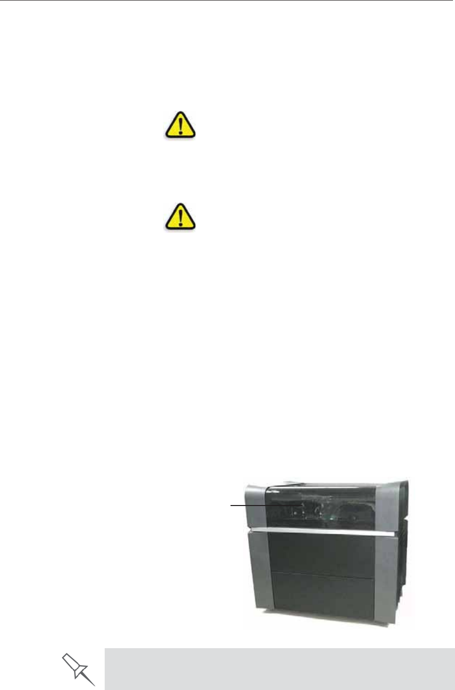
Safety Features
Stratasysȱ3DȱprintersȱareȱdesignedȱtoȱcomplyȱwithȱCEȱandȱFCCȱstandards.ȱ
Theyȱareȱequippedȱwithȱtheȱfollowingȱsafetyȱfeatures:
CoverȱInterlockȱ
Switch TheȱpowerȱsuppliedȱtoȱtheȱUVȱlampȱandȱtheȱ
motionȱmotorsȱisȱturnedȱoffȱwhenȱtheȱcoverȱisȱ
opened.
WARNING:ȱDoȱnotȱdefeatȱ(override)ȱtheȱ
interlockȱswitch.ȱDoingȱsoȱcouldȱresultȱinȱ
seriousȱpersonalȱinjury.ȱIfȱtheȱinterlockȱswitchȱ
doesȱnotȱfunctionȱcorrectly,ȱdoȱnotȱuseȱtheȱ
printer,ȱandȱcontactȱyourȱserviceȱprovider.
SafetyȱLock Theȱcoverȱisȱlockedȱwhileȱtheȱprinterȱisȱ
working.ȱTheȱlockȱisȱreleasedȱwhenȱtheȱprinterȱ
revertsȱtoȱpauseȱorȱstopȱmode.
WARNING:ȱDoȱnotȱdefeatȱ(override)ȱtheȱ
safetyȱlock.ȱDoingȱsoȱcouldȱresultȱinȱseriousȱ
personalȱinjury.ȱ
Ifȱtheȱsafetyȱlockȱdoesȱnotȱfunctionȱcorrectly,ȱdoȱ
notȱuseȱtheȱprinter,ȱandȱcontactȱyourȱserviceȱ
provider.
UVȱScreeningȱTheȱtransparentȱsectionȱofȱtheȱcoverȱblocksȱ
harmfulȱUVȱradiation,ȱallowingȱtheȱoperatorȱtoȱ
viewȱtheȱmodelȱasȱitȱisȱbeingȱmade.
CircuitȱBreaker Theȱpowerȱtoȱtheȱprinterȱisȱturnedȱoffȱinȱcaseȱofȱ
electricalȱovercurrent.ȱ
Note: The circuit breaker is only accessible to
service personnel.
UVȬLampȱ
Overheatingȱ
Protection
TheȱpowerȱsuppliedȱtoȱtheȱUVȱlampȱandȱtheȱ
motionȱmotorsȱisȱturnedȱoffȱifȱtheȱtemperatureȱ
aroundȱtheȱlampȱreachesȱ90ȱ°Cȱ(194ȱ°F).ȱ
AlabelonȱtheȱUVȬlampȱcoverȱindicatesȱifȱtheȱ
temperatureȱhasȱexceededȱ65ȱ°Cȱ(150ȱ°F).
GroundedȱChassis Theȱchassisȱofȱtheȱprinterȱisȱgrounded,ȱtoȱ
preventȱelectricalȱshock.
Note: The power outlet must be properly
grounded, in accordance with the local
electric code, to provide this protection.
UV screen
If the Stratasys 3D printing system is not used as specified in this guide, the
safety features may not provide adequate protection.
DOC08010 Rev. A (DRAFT 1) 2–3
Stratasys P750K User Guide
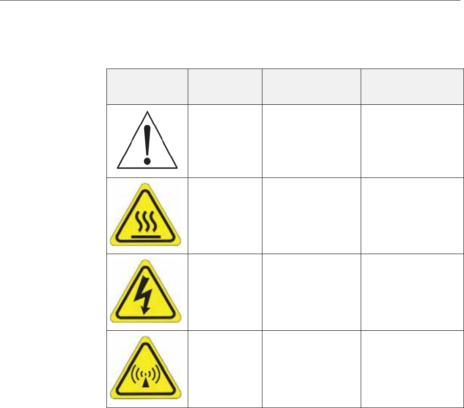
Symbols and Warning Labels
ThisȱfollowingȱtableȱlistsȱtheȱwarningȱlabelsȱlocatedȱonȱorȱinȱStratasysȱ
printers.
Warning
Symbol Meaning Location Comments
Hazardȱ
(general) Onȱtheȱnameȱplateȱ
onȱtheȱbackȱofȱtheȱ
printer.
Readȱtheȱinstructionsȱ
inȱthisȱdocumentȱ
beforeȱoperatingȱtheȱ
printer.
HotȱsurfaceȱOnȱtheȱprintȬheadȱ
block. Riskȱofȱburns.ȱDoȱnotȱ
touchȱthisȱsurfaceȱ
afterȱprinting.
HighȱvoltageȱNearȱtheȱUVȱlampȱ
connectors.
NearȱtheȱpowerȬ
supplyȱenclosures.
Riskȱofȱelectricȱshock.
Ultravioletȱ
radiation NearȱtheȱUVȱlamps. Riskȱofȱinjuryȱfromȱ
ultravioletȱradiation.

Safety
2–4 DOC08010 Rev. A (DRAFT 1)
Safety Guidelines
Theȱfollowingȱgeneralȱguidelines,ȱtogetherȱwithȱtheȱinstructionsȱprovidedȱ
throughoutȱthisȱuserȱguide,ȱensureȱuserȱsafetyȱwhileȱoperatingȱandȱ
maintainingȱtheȱsystem.ȱIfȱtheȱsystemȱisȱnotȱoperatedȱasȱspecified,ȱtheȱ
userȇsȱsafetyȱmayȱbeȱcompromised.
Printer
Installation ¾Installationȱandȱremovalȱofȱtheȱprinterȱshouldȱonlyȱbeȱdoneȱbyȱqualifiedȱ
serviceȱpersonnel.ȱ
¾Connectȱtheȱprinterȱ(andȱtheȱUPSȱunit)ȱtoȱtheȱelectricȱoutletȱusingȱaȱ
powerȱcordȱthatȱisȱsafetyȬcertified.
¾Theȱelectricȱoutletȱshouldȱbeȱeasilyȱaccessible,ȱnearȱtheȱprinter.
¾Neverȱconnectȱtheȱpowerȱplugȱtoȱanȱoutletȱthatȱdoesȱnotȱhaveȱaȱgroundȱ
(earth)ȱwire,ȱandȱneverȱdisconnectȱtheȱground.ȱDoingȱsoȱmightȱexposeȱ
theȱoperatorȱtoȱseriousȱdangerȱfromȱelectricȱshock.
¾TheȱfollowingȱsafetyȱstatementȱisȱfollowedȱbyȱtranslationsȱtoȱFinish,ȱ
Norwegian,ȱSwedishȱandȱDanish,ȱasȱrequiredȱbyȱlocalȱregulations:
“Theȱmachineȱmustȱbeȱconnectedȱtoȱaȱgroundedȱpowerȱoutlet.”
FI:ȱLaiteȱonȱliitettäväȱsuojakoskettimillaȱvarustettuunȱpistorasiaan.
NO:ȱApparatetȱmåȱtilkoplesȱjordetȱstikkontakt.
SE:ȱApparatenȱskallȱanslutasȱtillȱjordatȱuttag.
DK:ȱApparatetsȱstikpropȱskalȱtilsluttesȱenȱstikkontaktȱmedȱjord,ȱsomȱ
giverȱforbindelseȱtilȱstikproppensȱjord.
¾Leaveȱaȱminimumȱofȱ15ȱcentimetersȱbetweenȱventilationȱopeningsȱandȱ
wallsȱorȱotherȱobjects.
Printer
Operation ¾TheȱprinterȱshouldȱonlyȱbeȱoperatedȱbyȱpersonsȱtrainedȱbyȱaȱStratasysȱ
customerȬsupportȱrepresentative.
¾Allȱpersonnelȱoperatingȱorȱmaintainingȱtheȱprinterȱshouldȱknowȱtheȱ
locationȱofȱfirstȱaidȱandȱemergencyȱequipmentȱandȱhowȱtoȱuseȱit.ȱNeverȱ
blockȱaccessȱtoȱthisȱequipment.
¾Keepȱfingersȱandȱotherȱbodyȱpartsȱclearȱofȱtheȱprinterȱcoverȱwhenȱ
closingȱit.
¾Neverȱattemptȱtoȱopenȱtheȱprinterȱcoverȱwhileȱitȱisȱworking.
¾Neverȱoverrideȱtheȱinterlockȱsafetyȱswitch.
¾Ifȱtheȱinterlockȱsafetyȱswitchȱeverȱfails,ȱdoȱnotȱuseȱtheȱprinter.ȱ
¾Severalȱpartsȱofȱtheȱprinterȱremainȱextremelyȱhotȱevenȱafterȱitȱhasȱ
stoppedȱoperating.ȱAvoidȱtouchingȱtheȱUVȱlampsȱandȱtheȱprintȱblock.
UV Radiation TheȱUVȱlampsȱusedȱinȱtheȱprinterȱemitȱdangerousȱradiation.ȱ
¾IfȱtheȱUVȱlampsȱremainȱonȱwhenȱtheȱprinterȱisȱopen,ȱdoȱnotȱstareȱ
directlyȱatȱtheȱUVȱlight.ȱShutȱdownȱtheȱprinterȱandȱcallȱyourȱStratasysȱ
serviceȱprovider.
Printer
Maintenance ¾Serviceȱoperationsȱshouldȱbeȱperformedȱonlyȱbyȱqualifiedȱpersonnelȱ
whoȱhaveȱbeenȱinstructedȱinȱrelevantȱsafetyȱprecautions.
¾NotifyȱcoȬworkersȱandȱthoseȱwhoȱhaveȱaccessȱtoȱtheȱStratasysȱsystemȱ
beforeȱbeginningȱnonȬroutineȱandȱhazardousȱwork.
Report any potential dangers and safety-related accidents to your safety
officer or to other appropriate authorities.

DOC08010 Rev. A (DRAFT 1) 2–5
Stratasys P750K User Guide
Model and
Support
Materials
Modelȱandȱsupportȱmaterialsȱareȱmadeȱofȱchemicalȱsubstances.ȱAlthoughȱ
precautionsȱmustȱbeȱtakenȱwhenȱhandlingȱtheseȱmaterialsȱdirectly,ȱallȱ
modelȱandȱsupportȱmaterialsȱusedȱbyȱtheȱStratasysȱsystemȱareȱhandledȱinȱ
sealedȱcartridges.ȱNormally,ȱoperatorsȱofȱtheȱprinterȱshouldȱneverȱbeȱ
directlyȱexposedȱtoȱhazardousȱmaterials.ȱInȱtheȱunlikelyȱeventȱofȱaȱleakȱorȱ
spill,ȱfollowȱtheȱinstructionsȱthatȱareȱincludedȱwithȱtheȱprintingȬmaterialȱ
cartridgeȱused.
¾Storeȱmodelȱandȱsupportȱmaterialsȱindoors,ȱinȱaȱdryȱareaȱwithȱadequateȱ
ventilation,ȱbetweenȱ16Ȭ27ȱdegreesȱCelsiusȱ(60Ȭ81ȱdegreesȱFahrenheit).ȱ
Neverȱexposeȱthemȱtoȱflames,ȱheat,ȱsparks,ȱorȱdirectȱsunlight.
¾Keepȱmodelȱandȱsupportȱmaterialsȱawayȱfromȱareasȱwhereȱfoodȱandȱ
drinkȱareȱstored,ȱpreparedȱandȱconsumed.
¾Uncuredȱprintingȱmaterialȱisȱconsideredȱaȱhazardousȱsubstance,ȱ
requiringȱcertainȱprecautionsȱwhenȱdirectlyȱhandlingȱit.ȱToȱpreventȱskinȱ
irritation,ȱwearȱneopreneȱorȱnitrileȱgloves.ȱIfȱthereȱisȱanyȱchanceȱthatȱ
modelȱandȱsupportȱmaterialsȱmightȱsplashȱintoȱtheȱeyes,ȱwearȱsafetyȱ
goggles.ȱProlongedȱdirectȱcontactȱwithȱprintingȱmaterialsȱcanȱcauseȱanȱ
allergicȱreaction.
¾WhenȱhandlingȱUVȬcuredȱmodelsȱthatȱmayȱnotȱbeȱcompletelyȱcuredȱonȱ
theȱsurface,ȱcommonȱlatexȱglovesȱareȱadequate.ȱ
¾Toȱpreventȱrespiratoryȱirritation,ȱventilateȱareasȱwhereȱmodelȱandȱ
supportȱmaterialsȱareȱused.ȱIfȱtheȱprinterȱisȱnotȱequippedȱwithȱanȱ
exhaustȱduct,ȱtheȱroomȱventilationȱsystemȱshouldȱreplaceȱtheȱairȱatȱleastȱ
20ȱtimesȱperȱhour.ȱ
¾CleanȱupȱmodelȬmaterialȱandȱsupportȬmaterialȱspillsȱwithȱdisposableȱ
towelsȱorȱotherȱabsorbent,ȱnonȬreusableȱmaterial,ȱsuchȱasȱsawdustȱorȱ
activatedȱcharcoal.ȱRinseȱtheȱspillȱareaȱwithȱdenaturedȱorȱisopropylȱ
alcoholȱ(IPA),ȱfollowedȱbyȱsoapȱandȱwater.ȱDisposeȱofȱtheȱabsorbentȱ
materialȱinȱaccordanceȱwithȱlocalȱregulations.
¾Doȱnotȱwashȱcontaminatedȱclothingȱatȱhome;ȱclothingȱshouldȱbeȱ
professionallyȱlaundered.
¾Disposeȱofȱcontaminatedȱshoes,ȱbeltsȱandȱotherȱleatherȱitemsȱinȱ
accordanceȱwithȱanyȱapplicableȱregulations.ȱAbsorbedȱprintingȱ
materialȱmayȱreȬexposeȱtheȱuserȱwhenȱtheseȱitemsȱareȱworn.
UV Lamps UVȱlampsȱusedȱbyȱtheȱprinterȱtoȱcureȱprintingȱmaterialsȱcontainȱaȱsmallȱ
amountȱofȱmercury.ȱInȱtheȱunlikelyȱeventȱofȱlampȱbreakage,ȱavoidȱinhalingȱ
mercuryȱvapor,ȱandȱventilateȱtheȱroom.ȱIfȱtheȱlampȱrupturesȱ(breaks)ȱ
duringȱoperation,ȱleaveȱtheȱroomȱandȱventilateȱitȱthoroughlyȱ(forȱaboutȱ30ȱ
minutes).ȱ
Useȱprotectiveȱglovesȱtoȱpreventȱcontactȱwithȱmercuryȱandȱotherȱlampȱ
components.ȱCarefullyȱremoveȱspilledȱmercuryȱwithȱaȱmethodȱthatȱ
preventsȱtheȱgenerationȱofȱmercuryȱvapor,ȱsuchȱasȱaȱsyringe,ȱpackingȱtapeȱ
orȱpaper.ȱ
Placeȱtheȱbrokenȱlamp,ȱmercuryȱandȱcontaminatedȱmaterialsȱinȱanȱairȬtight,ȱ
nonȬmetallicȱcontainer.ȱDisposeȱofȱtheȱcontainerȱinȱaccordanceȱwithȱ
applicableȱregulations.

Safety
2–6 DOC08010 Rev. A (DRAFT 1)
First Aid for Working with Printing Materials
Inȱgeneral,ȱtryȱtoȱavoidȱdirectȱcontactȱwithȱuncuredȱprintingȱmaterial.ȱIfȱ
skinȱorȱeyesȱcomeȱintoȱcontactȱwithȱit,ȱwashȱtheȱareaȱimmediatelyȱandȱ
thoroughlyȱwithȱwater,ȱandȱfollowȱtheseȱfirstȬaidȱinstructions.
Contact with
Skin Ifȱuncuredȱprintingȱmaterialȱcomesȱinȱcontactȱwithȱskin,ȱwashȱtheȱaffectedȱ
areaȱimmediatelyȱandȱthoroughlyȱwithȱsoapȱandȱcoolȱwater,ȱthenȱremoveȱ
contaminatedȱclothing.ȱPayȱparticularȱattentionȱtoȱflushingȱtheȱhair,ȱears,ȱ
noseȱandȱotherȱpartsȱofȱtheȱbodyȱthatȱareȱnotȱeasilyȱcleaned.ȱ
¾Useȱcoolȱwaterȱtoȱpreventȱskinȱporesȱfromȱopening,ȱsoȱthatȱtheȱliquidȱ
materialȱdoesȱnotȱeasilyȱpenetrateȱtheȱskin.ȱ
¾Doȱnotȱuseȱsolventsȱtoȱcleanȱskin.ȱ
¾Ifȱlargeȱareasȱofȱskinȱhaveȱbeenȱexposed,ȱorȱifȱprolongedȱcontactȱresultsȱ
inȱblisters,ȱseekȱmedicalȱattention.ȱInȱanyȱcase,ȱifȱirritationȱpersists,ȱseekȱ
medicalȱattention.
¾Avoidȱtheȱaccidentalȱtransferȱofȱprintingȱmaterialȱfromȱtheȱhandsȱtoȱ
otherȱareasȱofȱtheȱbody,ȱespeciallyȱtoȱtheȱeyes.ȱ
¾Ifȱprotectiveȱcreamȱwasȱused,ȱdoȱnotȱreapplyȱitȱuntilȱtheȱskinȱhasȱbeenȱ
completelyȱcleansed.
Contact with
Eyes Ifȱuncuredȱprintingȱmaterialȱcomesȱinȱcontactȱwithȱtheȱeyes,ȱflushȱ
immediatelyȱwithȱlargeȱamountsȱofȱwaterȱforȱ15ȱminutesȱandȱseekȱmedicalȱ
attention.ȱ
¾Avoidȱsunlight,ȱfluorescentȱlight,ȱandȱotherȱsourcesȱofȱultravioletȱ
radiation.
Wearingȱcontactȱlensesȱwhenȱhandlingȱliquidȱprintingȱmaterialsȱisȱnotȱ
recommended.ȱIfȱtheȱliquidȱsplashesȱintoȱtheȱeyesȱwhenȱcontactȱlensesȱareȱ
worn,ȱimmediatelyȱremoveȱtheȱlensesȱandȱflushȱtheȱeyesȱwithȱwater.ȱ
¾Cleanȱandȱdisinfectȱtheȱcontaminatedȱlenses.
¾Doȱnotȱwearȱcontactȱlensesȱuntilȱeyeȱirritationȱdisappears.
Ingestion Ifȱprintingȱmaterialȱisȱswallowed,ȱreferȱtoȱtheȱinstructionsȱincludedȱwithȱtheȱ
cartridge.ȱSeekȱmedicalȱattentionȱimmediately.
Inhalation Vaporsȱfromȱprintingȱmaterialsȱcanȱbeȱirritatingȱtoȱtheȱrespiratoryȱsystem.ȱ
Ifȱrespiratoryȱirritationȱoccurs,ȱexposeȱtheȱvictimȱtoȱfreshȱairȱimmediately.
¾Ifȱtheȱvictimȱhasȱstoppedȱbreathing,ȱperformȱartificialȱrespirationȱorȱ
cardiopulmonaryȱresuscitation.ȱ
¾Seekȱmedicalȱattentionȱimmediately.
¾Keepȱtheȱvictimȱwarmȱbutȱnotȱhot.ȱ
¾Neverȱfeedȱanythingȱbyȱmouthȱtoȱanȱunconsciousȱperson.
¾Oxygenȱshouldȱbeȱadministeredȱbyȱauthorizedȱpersonnelȱonly.
The Material Safety Data Sheet (MSDS) that accompanies printing
materials contains important safety information. Keep this in an accessible
place where these materials are used and stored.

DOC08010 Rev. A (DRAFT 1) 2–7
Stratasys P750K User Guide
Waste Disposal
Fullyȱcuredȱprintedȱmodelsȱcanȱbeȱdisposedȱofȱasȱordinaryȱofficeȱtrash.ȱ
However,ȱspecialȱcareȱisȱrequiredȱwhenȱhandlingȱprinterȱwasteȱ(uncuredȱ
printingȱmaterial).
Printing Materials ¾WhenȱremovingȱtheȱwasteȱcontainerȱfromȱtheȱStratasysȱprinter,ȱwearȱ
neopreneȱorȱnitrileȱgloves.
¾Toȱpreventȱliquidȱwasteȱfromȱsplashingȱintoȱtheȱeyes,ȱwearȱsafetyȱ
goggles.
¾LiquidȱwasteȱfromȱtheȱStratasysȱprinterȱisȱclassifiedȱasȱhazardousȱ
industrialȱwaste.ȱTherefore,ȱprintingȬmaterialȱwasteȱmustȱbeȱpackagedȱ
andȱdisposedȱofȱinȱaȱmannerȱthatȱpreventsȱhumanȱcontactȱwithȱitȱandȱ
contaminationȱofȱwaterȱsources.
¾EmptyȱmodelȬmaterialȱandȱsupportȬmaterialȱcartridgesȱcontainȱresidueȱ
ofȱtheirȱcontents.ȱSomeȱleakageȱofȱthisȱresidueȱmayȱoccurȱthroughȱtheȱ
brokenȱcartridgeȱseal.ȱTherefore,ȱhandleȱandȱstoreȱemptyȱcartridgesȱ
withȱcare.ȱ
¾Doȱnotȱattemptȱtoȱreuseȱemptyȱcartridges,ȱandȱdoȱnotȱpunctureȱthem.
¾Disposeȱofȱusedȱcartridgesȱandȱwasteȱcontainersȱinȱaccordanceȱwithȱ
localȱregulations.
¾Discardȱcontaminatedȱclothing,ȱshoes,ȱemptyȱcontainers,ȱetc.,ȱinȱ
accordanceȱwithȱanyȱapplicableȱregulations.
UV Lamps UVȱlampsȱusedȱbyȱtheȱprinterȱtoȱcureȱprintingȱmaterialsȱcontainȱaȱsmallȱ
amountȱofȱmercury,ȱandȱareȱconsideredȱ“UniversalȱWaste.”ȱRecycleȱorȱ
discardȱusedȱlampsȱinȱaccordanceȱwithȱapplicableȱregulations.
Brokenȱlamps:ȱ
Afterȱventilatingȱtheȱarea,ȱuseȱprotectiveȱglovesȱandȱcarefullyȱremoveȱ
spilledȱmercuryȱwithȱaȱmethodȱthatȱpreventsȱtheȱgenerationȱofȱmercuryȱ
vapor,ȱsuchȱasȱaȱsyringe,ȱpackingȱtapeȱorȱpaper.ȱPlaceȱtheȱbrokenȱlamp,ȱ
mercuryȱandȱcontaminatedȱmaterialsȱinȱanȱairȬtight,ȱnonȬmetallicȱcontainer.ȱ
Disposeȱofȱtheȱcontainerȱinȱaccordanceȱwithȱapplicableȱregulations.

Safety
2–8 DOC08010 Rev. A (DRAFT 1)

DOC08010 Rev. A (DRAFT 1) 3–1
Introducing the Stratasys P750K
3D Printing System
WelcomeȱtoȱConnex .................................................................................... 2
WorkȱConfigurations .................................................................................. 2
SourceȱFiles................................................................................................... 3
STLȱFiles ..........................................................................................................3
SLCȱFiles..........................................................................................................3
ConnexȱWorkflows...................................................................................... 4
PrintingȱMaterials........................................................................................ 5
Storage .............................................................................................................5
ShelfȱLife..........................................................................................................5
ExposureȱtoȱLight...........................................................................................5
SafetyȱConsiderations....................................................................................6
Disposal...........................................................................................................6
WorkȱEnvironment...................................................................................... 6
WorkstationȱRequirements ........................................................................ 7
PreparingȱFilesȱforȱUseȱwithȱObjetȱ3DȱPrintingȱSystems ...................... 8
ConvertingȱCADȱFilesȱtoȱSTLȱFormat.........................................................8
ConvertingȱCADȱFilesȱtoȱSLCȱFormat.........................................................8
ObjetȱStudioȱSoftware................................................................................. 9

Introducing the Stratasys P750K 3D Printing System
3–2 DOC08010 Rev. A (DRAFT 1)
Welcome to Connex
TheȱadvancedȱcapabilitiesȱofȱConnex™ȱ3Dȱprintingȱsystemsȱareȱmadeȱ
possibleȱbyȱtechnologyȱspeciallyȱdevelopedȱbyȱStratasysȱforȱprintingȱ
modelsȱsimultaneouslyȱwithȱdifferentȱmodelȱmaterials.ȱ
WithȱConnexȱprinters,ȱyouȱcanȱachieveȱtheȱfollowingȱresultsȱwhenȱprintingȱ
3Dȱmodels:
•Youȱcanȱprepareȱobjectsȱforȱprintingȱwithȱtwoȱdesignatedȱmodelȱ
materialsȱandȱthenȱprintȱthemȱatȱtheȱsameȱtime.ȱThisȱenablesȱyouȱtoȱ
assignȱspecificȱmechanicalȱandȱcolorȱpropertiesȱtoȱobjects.
•Youȱcanȱprintȱpartsȱofȱtheȱsameȱmodel—simultaneously—withȱdifferentȱ
materialsȱ(orȱmaterialȱcombinations).
•Youȱcanȱprintȱobjectsȱthatȱhaveȱaȱ“coating”ȱmadeȱfromȱaȱdifferentȱ
materialȱthanȱtheȱmainȱpartȱofȱtheȱobject.
BecauseȱConnexȱprintersȱcanȱbeȱloadedȱwithȱdifferentȱmaterials,ȱyouȱcanȱ
streamlineȱandȱeconomizeȱtheȱprocessȱofȱproducingȱmodels:
•Printingȱmodelsȱmadeȱfromȱdifferentȱmaterialsȱonȱtheȱsameȱbuildȱtrayȱ
(“mixedȱtray”),ȱinȱtheȱsameȱprintȱjob,ȱeliminatesȱtheȱtimeȬconsumingȱ
needȱandȱexpenseȱofȱloadingȱanotherȱmaterial,ȱflushingȱtheȱsystem,ȱandȱ
sendingȱaȱseparateȱjobȱtoȱbeȱprinted.
ObjetȱStudioȱenablesȱyouȱtoȱsplitȱmodelsȱintoȱcomponentȱpartsȱ(“shells”)ȱsoȱ
youȱcanȱisolate,ȱmanipulateȱandȱprintȱpartsȱofȱaȱmodel.ȱThen,ȱyouȱcanȱ
assignȱmodelȱmaterialsȱandȱotherȱcharacteristicsȱtoȱtheȱshells.ȱHowever,ȱ
youȱhaveȱultimateȱcontrolȱwhenȱseparatingȱmodelsȱintoȱshellsȱbyȱpreparingȱ
stlȱfilesȱwithȱyourȱCADȱsoftware.
Figure 3-1: The Stratasys P750K 3D Printer
Work Configurations
TheȱStratasysȱ3DȱprintingȱsystemȱcanȱbeȱsetȱupȱasȱaȱsingleȬstationȱsystemȱorȱ
asȱaȱmultiȬstationȱsystem.ȱWhenȱconnectedȱtoȱaȱlocalȱcomputerȱnetwork,ȱtheȱ
systemȱcanȱserveȱmultipleȱusers.ȱInȱsuchȱconfigurations,ȱeachȱuserȱ
workstationȱ(client)ȱpreparesȱfilesȱwithȱObjetȱStudioȱsoftwareȱforȱ
production.ȱAȱserverȱ(host),ȱtypicallyȱnextȱtoȱtheȱ3Dȱprinter,ȱactsȱasȱaȱjobȱ
managerȱthatȱsendsȱproductionȱjobsȱtoȱtheȱprinterȱforȱproduction.ȱ
Figure 3Ȭ2ȱshowsȱtheȱprinterȱsetȱupȱinȱaȱmultiȬclientȱconfiguration.
Figure 3-2: Multi-client network configuration
WhenȱinstallingȱObjetȱStudio,ȱyouȱchooseȱwhetherȱtoȱinstallȱitȱasȱaȱclientȱ
stationȱorȱasȱaȱmasterȱstationȱ(serverȱorȱstandaloneȱstation).
ObjetȱStudioȱarrangesȱtheȱjobsȱitȱreceivesȱaccordingȱtoȱtheirȱpriorities,ȱ
modelȬmaterialȱtype,ȱandȱotherȱfactors.ȱInȱmultiȬworkstationȱ
configurations,ȱtheȱoperatorȱofȱtheȱserver—typicallyȱtheȱproductionȱ
administrator—hasȱtotalȱcontrolȱoverȱtheȱjobsȱsentȱtoȱtheȱ3Dȱprinter,ȱandȱ
canȱprioritizeȱandȱdeleteȱjobs,ȱreviewȱjobȱhistoryȱandȱreprintȱaȱjob,ȱandȱsoȱ
on.

DOC08010 Rev. A (DRAFT 1) 3–3
Stratasys P750K User Guide
Source Files Objetȱ3DȱprintingȱsystemsȱproduceȱthreeȬdimensionalȱmodelsȱdesignedȱ
withȱmostȱ3DȱCADȱtoolsȱandȱwithȱotherȱjobȬspecificȱ3Dȱapplications.ȱ
Stratasysȱsystemsȱaccept:
•STLȱFiles
•SLCȱFiles
Stratasysȱsystemsȱfeatureȱtheȱcapabilityȱofȱproducingȱdifferentȱtypesȱofȱ
modelȱfilesȱsimultaneously.
STL Files STLȱisȱshortȱforȱStandardȱTriangulationȱLanguage.ȱThisȱlanguageȱviewsȱanyȱ
objectȱasȱaȱcollectionȱofȱsurfaces,ȱandȱdescribesȱeachȱsurfaceȱofȱtheȱobjectȱasȱ
aȱcollectionȱofȱtriangles.ȱ
Forȱexample,ȱaȱsquareȱcanȱbeȱdescribedȱasȱtwoȱtriangles;ȱaȱcubeȱ(sixȱ
squares)ȱasȱ12ȱtriangles.ȱCurvedȱsurfacesȱneedȱmoreȱtrianglesȱtoȱdescribeȱ
them.ȱTheȱhigherȱtheȱtoleranceȱ(forȱsmoothȱsurfaces),ȱtheȱmoreȱtrianglesȱareȱ
needed.ȱTheȱresultȱisȱthatȱhighȬqualityȱobjectȱdescriptionsȱmeanȱveryȱheavyȱ
files.ȱ
MostȱCADȱsoftwareȱcanȱexportȱSTLȱfiles.ȱTheȱStratasysȱsystemȱutilizesȱ
theseȱfilesȱforȱbuildingȱmodelsȱ(rapidȱprototyping),ȱandȱalsoȱforȱdirectlyȱ
makingȱmoldsȱforȱmassȬproducingȱitems.
STLȱfilesȱcanȱbeȱASCIIȱ(text)ȱfilesȱorȱbinaryȱfiles.ȱTheȱcontentȱofȱtheȱASCIIȱ
fileȱbeginsȱwithȱ“solid”ȱandȱendsȱwithȱ“endȬsolid”ȱ(bothȱlowerȱcase).ȱ
Betweenȱtheseȱkeywordsȱisȱaȱlistȱofȱtheȱtrianglesȱthatȱdescribesȱtheȱfacesȱofȱ
theȱsolidȱmodel.ȱEachȱtriangleȱdefinesȱaȱsingleȱnormalȱvectorȱdirectedȱawayȱ
fromȱtheȱsolid’sȱsurface,ȱfollowedȱbyȱitsȱXȬYȬZȱcoordinates.ȱTheseȱareȱ
expressedȱasȱCartesianȱcoordinatesȱandȱareȱfloatingȬpointȱvalues.ȱTheȱ
coordinatesȱofȱallȱtrianglesȱshouldȱbeȱpositiveȱandȱshouldȱfallȱwithinȱtheȱ
volumeȱofȱtheȱmodel.ȱ
SLC Files SLCȱisȱshortȱforȱStereoȬLithographyȱContour.ȱSLCȱfilesȱdescribeȱtwoȬ
dimensionalȱcontoursȱofȱtheȱthreeȬdimensionalȱmodels.ȱTheseȱcontourȱlinesȱ
areȱpolylines.ȱ
SLCȱfilesȱareȱASCIIȱ(text)ȱfilesȱthatȱsaveȱmodelsȱasȱaȱseriesȱofȱslices.ȱThisȱ
meansȱthatȱmodelsȱbasedȱonȱSLCȱfilesȱcannotȱbeȱorientated;ȱonlyȱtheirȱscaleȱ
(size)ȱandȱpositionȱonȱtheȱbuildȱtrayȱcanȱbeȱcontrolled.ȱForȱthisȱreason,ȱtheȱ
model’sȱorientationȱmustȱbeȱsuitableȱforȱproductionȱbeforeȱitȱisȱsavedȱasȱanȱ
SLCȱfile.ȱBecauseȱofȱtheȱnatureȱofȱSLCȱfiles,ȱtheȱappearanceȱofȱmodelsȱinȱ
ObjetȱStudioȱmayȱbeȱdifferentȱthanȱtheȱsolidȬobjectȱimagesȱdisplayedȱfromȱ
STLȱfiles.
Introducing the Stratasys P750K 3D Printing System
3–4 DOC08010 Rev. A (DRAFT 1)
Connex Workflows
WithȱConnexȱ3Dȱprintingȱsystems,ȱyouȱhaveȱgreatȱflexibilityȱinȱpreparingȱ
modelȱfilesȱandȱprintingȱthem.ȱBelowȱareȱtheȱmajorȱworkflowsȱyouȱcanȱuse.ȱ
Detailedȱinstructionsȱforȱimplementingȱtheȱlistedȱtasksȱareȱinȱchapterȱ5ȱ
(“UsingȱObjetȱStudio”).
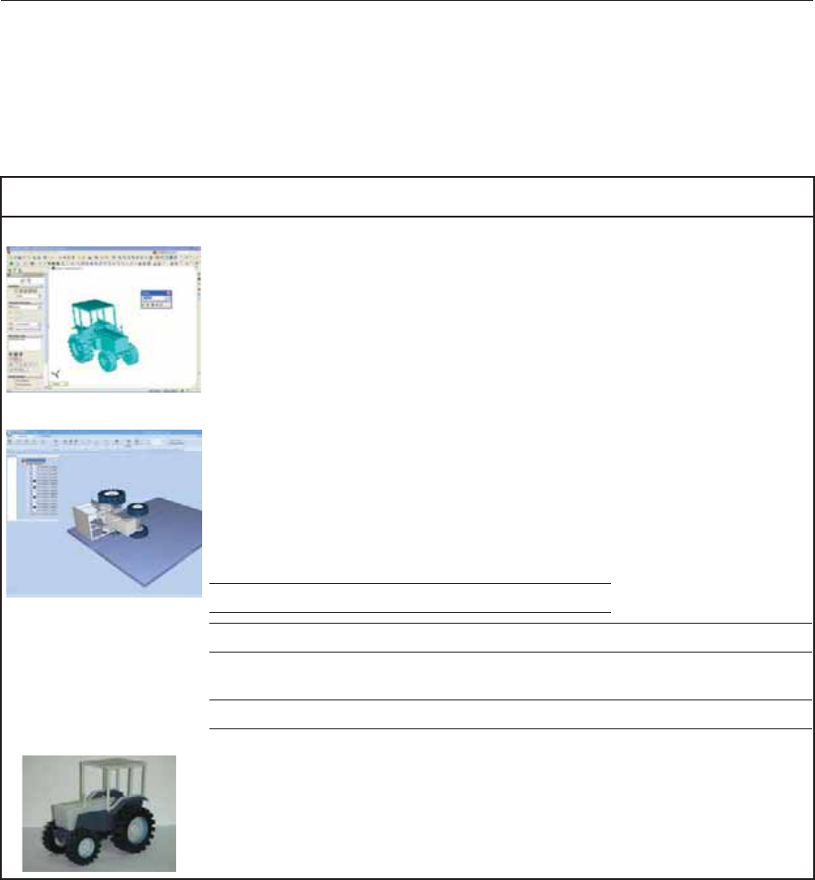
Connexȱworkflows,ȱfromȱdesignȱtoȱfinishedȱmodels
Stage WorkflowȱAWorkflowȱBWorkflowȱC
CADȱprogram •Designȱaȱ3Dȱobject.
•Saveȱitȱasȱaȱsingleȱstlȱ
file.
•Designȱaȱ3Dȱobject.
•Saveȱitȱasȱanȱ
assemblyȱofȱstlȱfiles.
•Designȱaȱ3Dȱobject.
ObjetȱStudio •Openȱ(Insert)ȱtheȱstlȱ
file.
•Separateȱtheȱobjectȱ
intoȱitsȱcomponentsȱ
(“shells”).
•Assignȱmaterialsȱtoȱ
theȱcomponents.
•Openȱ(Insert)ȱtheȱstlȱ
filesȱasȱanȱassembly.
•Assignȱmaterialsȱtoȱ
theȱassembly’sȱ
components.
•Openȱ(Insert)ȱanȱ
objdfȱfile.ȱ
(objdfȱfilesȱcontainȱ
modelȬmaterialȱ
information.)
•ȱSaveȱtheȱobjectȱasȱanȱobjdfȱfileȱ(optional).
•ȱSaveȱtheȱbuildȱtray.ȱ/ȱSendȱtheȱbuildȱtoȱtheȱprinter.
StratasysȱPrinter Modelsȱareȱproducedȱinȱtheȱprinter.
•ȱRemoveȱtheȱsupportȱmaterialȱfromȱtheȱmodels.
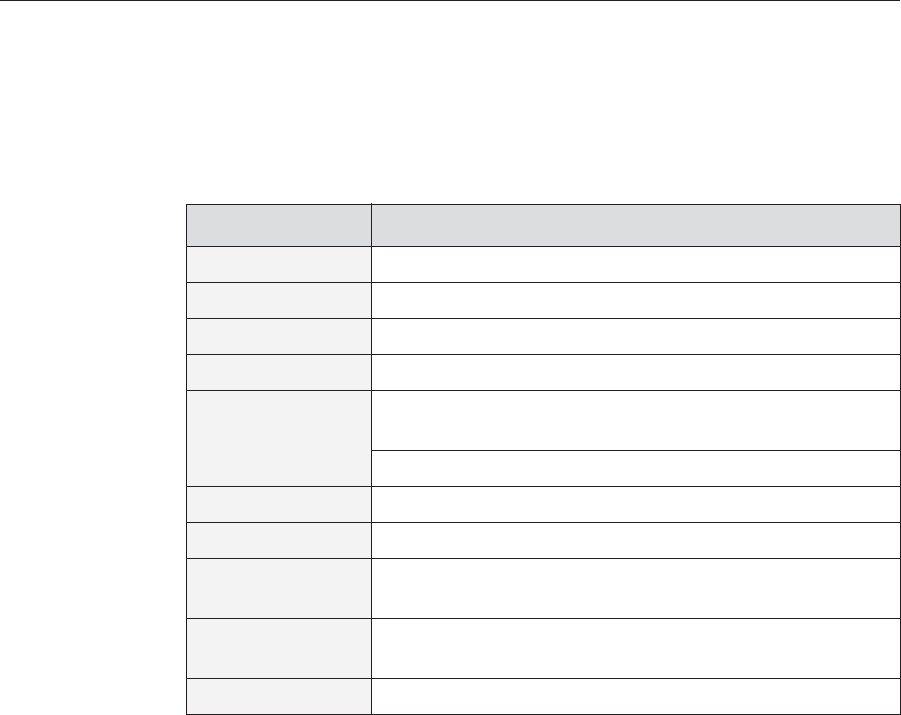
Finishedȱmodel
Finishedȱmodel.

DOC08010 Rev. A (DRAFT 1) 3–5
Stratasys P750K User Guide
Printing Materials
Stratasysȱprintersȱproduceȱmodelsȱbyȱjettingȱthinȱlayersȱofȱprintingȱ
materialsȱonȱtheȱbuildȱtray,ȱuntilȱtheȱcompleteȱmodelȱisȱformed.ȱTwoȱtypesȱ
ofȱmaterialȱareȱusedȱinȱthisȱprocess:
•Modelȱmaterial—whichȱmakesȱupȱtheȱfinishedȱmodel
•Supportȱmaterial—whichȱfillsȱgapsȱandȱspacesȱinȱtheȱmodelȱduringȱ
printing,ȱandȱisȱremovedȱafterȱprinting
Storage MaterialsȱusedȱforȱprintingȱmodelsȱwithȱStratasysȱprintersȱareȱmadeȱofȱ
resins,ȱwhichȱareȱcomposedȱofȱreactiveȱmonomersȱandȱoligomers.ȱ
Althoughȱprintingȱmaterialsȱareȱsuppliedȱinȱsealed,ȱUVȬproofȱcartridges,ȱ
careȱmustȱbeȱtakenȱwhenȱstoringȱandȱhandlingȱthem.ȱFollowȱtheseȱ
guidelinesȱtoȱprotectȱoperatorsȱandȱtheȱenvironment,ȱandȱtoȱensureȱ
optimumȱresults.ȱ
•Toȱensureȱproductȱstability,ȱdoȱnotȱallowȱtheseȱmaterialsȱtoȱcomeȱintoȱ
contactȱwithȱmetal.ȱPlasticsȱmadeȱfromȱmonomerȬsolubleȱsubstancesȱ
(suchȱasȱpolystyreneȱorȱpolyvinylȱchloride)ȱareȱnotȱsuitableȱforȱstoringȱ
PolyJetȱprintingȱmaterials.
•Whenȱnotȱinȱuse,ȱkeepȱmaterialȱcartridgesȱtightlyȱsealedȱtoȱpreventȱ
contamination,ȱtheȱeffectsȱofȱexposureȱtoȱUVȱradiation,ȱandȱaccidentalȱ
spillage.ȱ
•Storeȱmaterialȱcartridgesȱindoors,ȱinȱaȱdryȱareaȱwithȱadequateȱ
ventilation,ȱbetweenȱ16–27ȱdegreesȱCelsiusȱ(60–81ȱdegreesȱFahrenheit).ȱ
Ifȱexposedȱtoȱheatȱorȱflames,ȱcartridgesȱmightȱburstȱorȱignite.
•Signsȱofȱprematureȱpolymerizationȱinȱmaterialȱcartridgesȱincludeȱ
bulging,ȱleaking,ȱtheȱemissionȱofȱheat,ȱandȱunusualȱodor.ȱExposureȱtoȱ
heatȱcanȱcauseȱresinȱtoȱgelȱinȱtheȱcartridge.
•Makeȱsureȱthatȱmaterialȱcartridgesȱareȱstoredȱinȱaccordanceȱwithȱallȱ
localȱregulationsȱandȱotherȱapplicableȱrequirements.
Shelf Life Materialsȱusedȱforȱproducingȱmodelsȱhaveȱaȱlimitedȱshelfȱlife.ȱTheȱexpiryȱ
dateȱonȱtheȱlabelȱisȱvalidȱwhenȱproperlyȱstoredȱinȱanȱundamaged,ȱ
unopenedȱcartridge.ȱAlwaysȱrotateȱyourȱstock,ȱsoȱthatȱtheȱcartridgeȱwithȱ
theȱearliestȱdateȱisȱusedȱfirst.
Exposure to
Light Ifȱprintingȱmaterialsȱareȱnotȱinȱtheirȱsealedȱcartridges,ȱmakeȱsureȱtoȱshieldȱ
themȱfromȱsunlightȱandȱotherȱsourcesȱofȱUVȱradiation,ȱsuchȱasȱfluorescentȱ
andȱmercuryȬvaporȱlights.ȱExposureȱtoȱUVȱradiationȱcausesȱanȱincreaseȱinȱ
viscosityȱand,ȱeventually,ȱsolidification.
For up-to-date information about PolyJet printing materials and their
properties, go to http://www.stratasys.com/materials/polyjet.

Introducing the Stratasys P750K 3D Printing System
3–6 DOC08010 Rev. A (DRAFT 1)
Safety
Considerations Beforeȱbeingȱcured,ȱresinsȱareȱhazardousȱmaterials.ȱToȱpreventȱpossibleȱ
healthȱhazards,ȱfollowȱtheseȱprecautionsȱregardingȱprintingȱmaterials:ȱ
•Doȱnotȱexposeȱtoȱflames,ȱheatȱorȱsparks.
•Preventȱcontactȱwithȱskinȱandȱeyes.
•Ventilateȱareasȱwhereȱtheyȱareȱhandled.ȱ
•Keepȱthemȱseparateȱfromȱfoodȱandȱdrink.
Curedȱplasticȱparts,ȱhowever,ȱareȱsafe.ȱTheyȱcanȱbeȱhandledȱandȱstoredȱ
withoutȱprecautions.
Disposal Disposeȱofȱcartridgesȱofȱmodelȱandȱsupportȱmaterialȱinȱaccordanceȱwithȱallȱ
applicableȱlawsȱandȱregulations.ȱIfȱnecessary,ȱtheȱcartridgesȱcanȱbeȱ
disassembledȱforȱrecycling.ȱ
Work Environment
Extremeȱheatȱandȱhumidityȱconditionsȱcanȱadverselyȱaffectȱtheȱoperationȱofȱ
theȱStratasysȱ3Dȱprinter.ȱUseȱventilationȱorȱairȬconditioningȱsystems,ȱifȱ
necessary,ȱtoȱkeepȱtheȱworkȱareaȱwithinȱtheȱfollowingȱranges:
•18q–25qȱCȱ(64q–77qȱF)
•30%–70%ȱrelativeȱhumidity
You can find more safety information about resins in “Safety Guidelines” on
page 2-4, and “First Aid for Working with Printing Materials” on page 2-6.
DOC08010 Rev. A (DRAFT 1) 3–7
Stratasys P750K User Guide
Workstation Requirements
Theȱtableȱbelowȱlistsȱtheȱrequirementsȱforȱcomputerȱcomponentsȱonȱ
workstationsȱrunningȱObjetȱStudio.
Important:ȱȱMakeȱsureȱthatȱtheȱserverȱworkstationȱisȱsetȱupȱwithȱ
Administratorȱprivileges.
Requirement
Computer Type Server workstation: Standard desktop PC1
Processor Intel® Core™ i3 or better
Operating System Windows® 7 or Windows® 8, 64-bit2
RAM 8 GB or more2
Graphics Card3
Open GL®
Memory: 1 GB; 2 GB recommended for dental applications
For server workstation: VGA connector4
Optical Drive CD/DVD ROM
Hard-Disk Drive 80 GB or larger (minimum free space: 40 GB)
Network Card LAN TCP/IP
(2 for server workstation; 1 for client workstation)
Mouse/Keyboard
Connection Server workstation: USB1
Monitor Cable VGA connector1
1. ForȱsystemsȱusingȱaȱKVMȱswitchboxȱtoȱcontrolȱbothȱtheȱbuiltȬinȱ
printerȱcomputerȱandȱtheȱserverȱworkstationȱwithȱsameȱkeyboardȬ
monitorȬmouseȱset:ȱAllȬinȬoneȱcomputer,ȱwirelessȱmouseȱandȱ
wirelessȱkeyboardȱcannotȱbeȱused.
2. Aȱ64Ȭbitȱoperatingȱsystemȱisȱrecommended,ȱtoȱutilizeȱ8ȱGBȱofȱ
memory.ȱObjet Studioȱrunningȱonȱaȱ32Ȭbitȱapplicationȱcanȱutilizeȱ
onlyȱ4ȱGBȱofȱmemory.
3. TheȱfollowingȱgraphicsȱcardsȱwereȱtestedȱinȱStratasysȱlabs:
•ȱNVIDIA®ȱQuadro®ȱFamily—FX570,ȱFX1700
•ȱNVIDIA®ȱGeForce®ȱFamily—6200ȱTurboCache™,ȱ7300ȱGT,ȱGTXȱ285
•ȱIntel®ȱExpressȱChipset—82915G/GV,ȱ82910GL,ȱQ965,ȱQ963,ȱQ35,ȱQ45,ȱQ43,ȱ
82852,ȱ82855
•ȱATIȱRadeon™ȱHDȱ5670,ȱHDȱ5970
•ȱAMDȱRadeon™ȱE6760
4. ForȱsystemsȱusingȱaȱKVMȱswitchbox.ȱIfȱtheȱserverȱworkstationȱhasȱ
aȱDVIȱvideoȱconnector,ȱaȱVGAȱadapterȱisȱneeded.

Introducing the Stratasys P750K 3D Printing System
3–8 DOC08010 Rev. A (DRAFT 1)
Preparing Files for Use with Objet 3D Printing Systems
BeforeȱusingȱfilesȱwithȱStratasysȱ3Dȱprintingȱsystems,ȱyouȱneedȱtoȱconvertȱ
themȱinȱyourȱCADȱprogramȱtoȱaȱfileȱformatȱsupportedȱbyȱObjetȱStudio.ȱ(Forȱ
anȱexplanationȱofȱtheseȱfileȱformats,ȱseeȱ“SourceȱFiles”ȱonȱpage 3.)
Converting
CAD Files to
STL Format
Thisȱprocedureȱmayȱvaryȱslightly,ȱdependingȱonȱtheȱCADȱsoftwareȱused,ȱ
butȱtheȱfollowingȱinstructionsȱgenerallyȱapply.
To convert a file to STL format (in a CAD program):
1. FromȱtheȱFileȱmenu,ȱselectȱSave As.
2. InȱtheȱSaveȱAsȱdialogȱbox,ȱopenȱtheȱSaveȱAsȱTypeȱdropȬdownȱlistȱandȱ
selectȱ*.STL.
3. ClickȱOptionsȱandȱsetȱtheȱfollowingȱparameters:
•TotalȱQuality—approximatelyȱ0.01ȱmmȱ(deviationȱtoleranceȱ/ȱ
linearȬdimensionȱtolerance)
•DetailȱQuality—approximatelyȱ5°ȱ(angleȱtolerance)
Note: Lowering these values produces more accurate models, but
results in larger files and longer loading and processing times. For this
reason, it is generally not recommended that you use lower values.
4. Inȱtheȱfileȱformatȱoption,ȱchooseȱbinaryȱorȱASCII.ȱ(Bothȱbinaryȱandȱ
ASCIIȱformatsȱcanȱbeȱusedȱinȱObjetȱStudio.ȱHowever,ȱbinaryȱfilesȱareȱ
smaller,ȱsoȱthisȱoptionȱisȱrecommended.)
5. ClickȱOKȱorȱSave.
Afterȱconvertingȱtheȱmodelȱfiles,ȱitȱisȱrecommendedȱthatȱyouȱcheckȱthemȱforȱ
defectsȱinȱanȱSTLȬrepairȱapplicationȱ(suchȱasȱMagics™,ȱbyȱMaterialise®)ȱ
beforeȱopeningȱthemȱinȱObjetȱStudioȱandȱproducingȱtheȱmodel.
Converting
CAD Files to
SLC Format
WhenȱconvertingȱfilesȱtoȱSLCȱformat,ȱitȱisȱrecommendedȱthatȱyouȱsetȱaȱlayerȱ
thicknessȱofȱ15ȱmicronsȱ(0.015ȱmm).ȱSinceȱSLCȱfilesȱcannotȱbeȱorientatedȱinȱ
ObjetȱStudio,ȱitȱisȱimportantȱthatȱmodelsȱareȱproperlyȱorientatedȱbeforeȱ
beingȱsavedȱasȱSLCȱfiles.ȱConsiderationsȱforȱsuitableȱmodelȱorientationȱareȱ
explainedȱinȱ“ModelȱOrientation”ȱonȱpage 5Ȭ26.
For more information, search for “CAD to STL” on www.stratasys.com.

DOC08010 Rev. A (DRAFT 1) 3–9
Stratasys P750K User Guide
Objet Studio Software
ObjetȱStudioȱsoftwareȱforȱtheȱStratasysȱ3Dȱprintingȱsystemȱconsistsȱofȱtwoȱ
mainȱscreens:
•TrayȱSettingsȱ/ȱModelȱSettings
•JobȱManager
Tray Settings / Model Settings
InȱtheȱTrayȱSettingsȱandȱModelȱSettingsȱscreens,ȱyouȱprepareȱsourceȱfilesȱforȱ
productionȱinȱStratasysȱ3Dȱprinters.ȱObjetȱStudioȱoffersȱyouȱaȱwideȱvarietyȱ
ofȱfileȬpreparationȱoptions,ȱbutȱalwaysȱconsistsȱofȱtheȱfollowingȱbasicȱ
procedure:
1. Insertingȱoneȱorȱmoreȱobjectsȱonȱtheȱbuildȱtray
2. Positioningȱtheȱobject(s)ȱonȱtheȱtray
3. Configuringȱobjectȱandȱtrayȱparameters
4. Savingȱtheȱtrayȱconfigurationȱasȱanȱobjtfȱ(ObjetȱTrayȱFormat)ȱfile
5. SendingȱtheȱobjtfȱfileȱtoȱtheȱStratasysȱ3Dȱprinterȱforȱproduction
UsingȱObjetȱStudioȱtoȱperformȱtheseȱtasksȱisȱdescribedȱinȱdetailȱinȱchapter 5,ȱ
“UsingȱObjetȱStudio.”
Job Manager
TheȱJobȱManagerȱscreenȱisȱdifferentȱforȱclientȱworkstationsȱandȱforȱtheȱ
computerȱconnectedȱdirectlyȱtoȱtheȱStratasysȱ3Dȱprinter.ȱ
•InȱObjetȱStudioȱinstalledȱonȱtheȱdirectlyȬconnectedȱcomputerȱ(server),ȱ
theȱJobȱManagerȱscreenȱdisplaysȱtheȱqueueȱandȱstatusȱforȱallȱjobsȱsentȱtoȱ
theȱ3Dȱprinterȱbyȱtheȱserverȱitselfȱandȱbyȱallȱclientȱcomputersȱonȱtheȱ
network.ȱAllȱjobsȱdisplayedȱcanȱbeȱeditedȱandȱmanipulated.ȱ
•InȱObjetȱStudioȱinstalledȱonȱclientȱcomputers,ȱtheȱJobȱManagerȱscreenȱ
displaysȱtheȱqueueȱandȱstatusȱonlyȱforȱjobsȱsentȱtoȱaȱ3Dȱprinterȱserverȱ
fromȱthatȱcomputer.ȱOnlyȱtheseȱjobsȱcanȱbeȱeditedȱandȱmanipulatedȱ
fromȱtheȱclientȱcomputer.
Client computers can be connected, via the local network, to different Objet
3D printers, but only to one at a time. The Job Manager screen displays the
status of the 3D printer to which the client is currently connected.

Introducing the Stratasys P750K 3D Printing System
3–10 DOC08010 Rev. A (DRAFT 1)

DOC08010 Rev. A (DRAFT 1) 4–1
Installing Objet Software
HowȱtoȱInstallȱSoftwareȱforȱtheȱStratasysȱ3D Printing System..................... 2
Installing Objet Software
4–2 DOC08010 Rev. A (DRAFT 1)
How to Install Software for the Stratasys 3D Printing System
TheȱObjetȱStudioȱsetupȱwizardȱguidesȱyouȱwhenȱinstallingȱthisȱsoftware.ȱ
ObjetȱStudioȱisȱinstalledȱonȱtheȱprinterȬserverȱ(“host”)ȱcomputer,ȱbutȱitȱcanȱ
alsoȱbeȱinstalledȱonȱremote,ȱ“client”ȱcomputersȱandȱonȱcomputersȱusedȱtoȱ
prepareȱfilesȱforȱprintingȱmodels,ȱorȱforȱtrainingȱandȱdemonstrationȱ
purposes.ȱDuringȱinstallation,ȱyouȱchooseȱtoȱinstallȱeitherȱtheȱprinterȬserverȱ
(“host”)ȱapplicationȱorȱtheȱclientȱapplication.ȱ
To install Objet software:
1. InsertȱtheȱObjetȱStudioȱCDȱintoȱtheȱdiskȱdrive.
2. RightȬclickȱtheȱStartȱbuttonȱandȱselectȱExploreȱ(orȱuseȱanyȱotherȱmethodȱ
forȱdisplayingȱfilesȱonȱtheȱcomputer).
3. OpenȱtheȱCDȬdriveȱfolderȱandȱselectȱSetup.
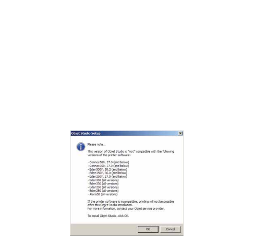
4. IfȱyouȱareȱinstallingȱanȱObjetȱStudioȱupgrade,ȱmakeȱsureȱthatȱyourȱ
printerȱisȱcompatibleȱwithȱitȱbyȱcheckingȱtheȱlistȱdisplayed.
Figure 4-1:Objet Studio compatibility check
5. ToȱinstallȱObjetȱStudio,ȱyouȱmustȱagreeȱtoȱtheȱlicenseȱagreement.ȱAfterȱ
readingȱitsȱterms,ȱclickȱYesȱtoȱcontinue,ȱorȱNoȱtoȱcloseȱtheȱwizard.
DOC08010 Rev. A (DRAFT 1) 4–3
Stratasys P750K User Guide
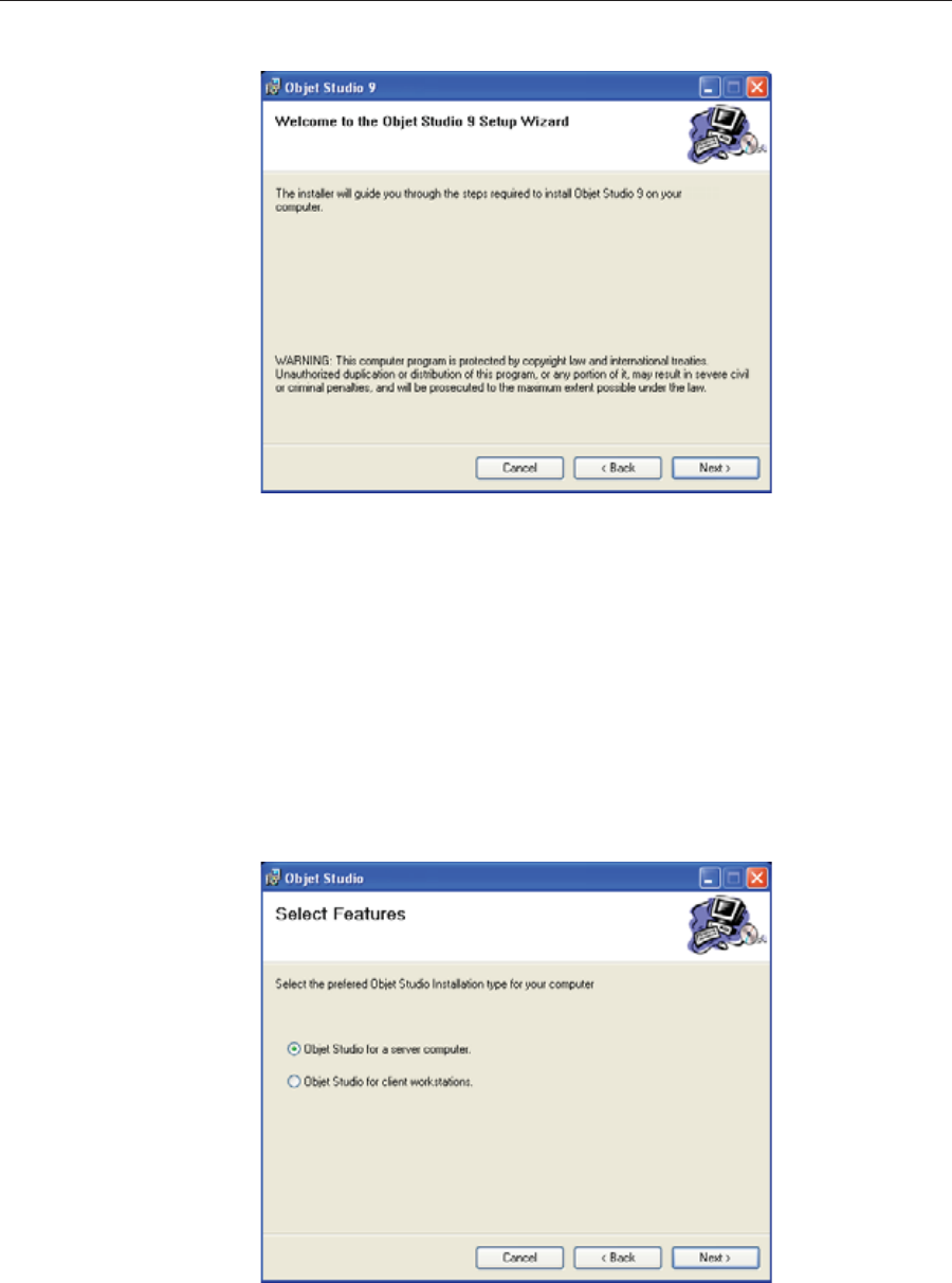
IfȱyouȱclickȱYes,ȱtheȱfollowingȱscreenȱshouldȱappear.ȱ
Figure 4-2: Objet Studio installation wizard—Welcome screen
6. ClickȱNextȱtoȱbeginȱinstallation.
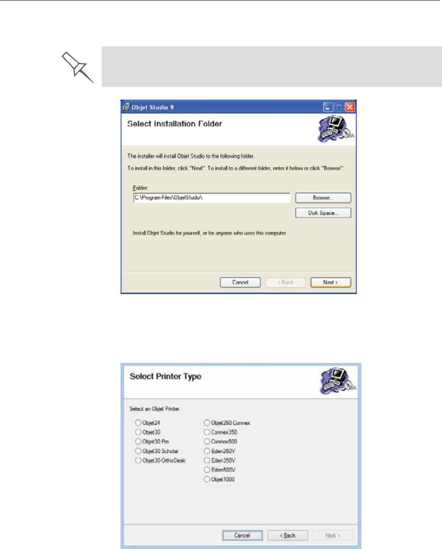
7. InȱtheȱSelectȱFeaturesȱscreen,ȱselectȱtheȱrequiredȱinstallationȱoption.
SelectȱObjet Studio for a server computer...
•ifȱyouȱareȱinstallingȱObjetȱStudioȱonȱtheȱserverȱ(“host”)ȱcomputer—
theȱcomputerȱdirectlyȱconnectedȱtoȱanȱStratasysȱprinter.
•ifȱyouȱareȱinstallingȱObjetȱStudioȱonȱaȱstandaloneȱ(offȬline)ȱ
computer.
SelectȱObjet Studio for client workstations ifȱyouȱareȱinstallingȱObjetȱ
Studioȱonȱaȱ“client”ȱworkstation—aȱremoteȱcomputerȱthatȱpreparesȱ
printȱjobsȱandȱthenȱsendsȱthemȱtoȱaȱserverȱcomputer.
Figure 4-3: Objet Studio configuration selection
Installing Objet Software
4–4 DOC08010 Rev. A (DRAFT 1)
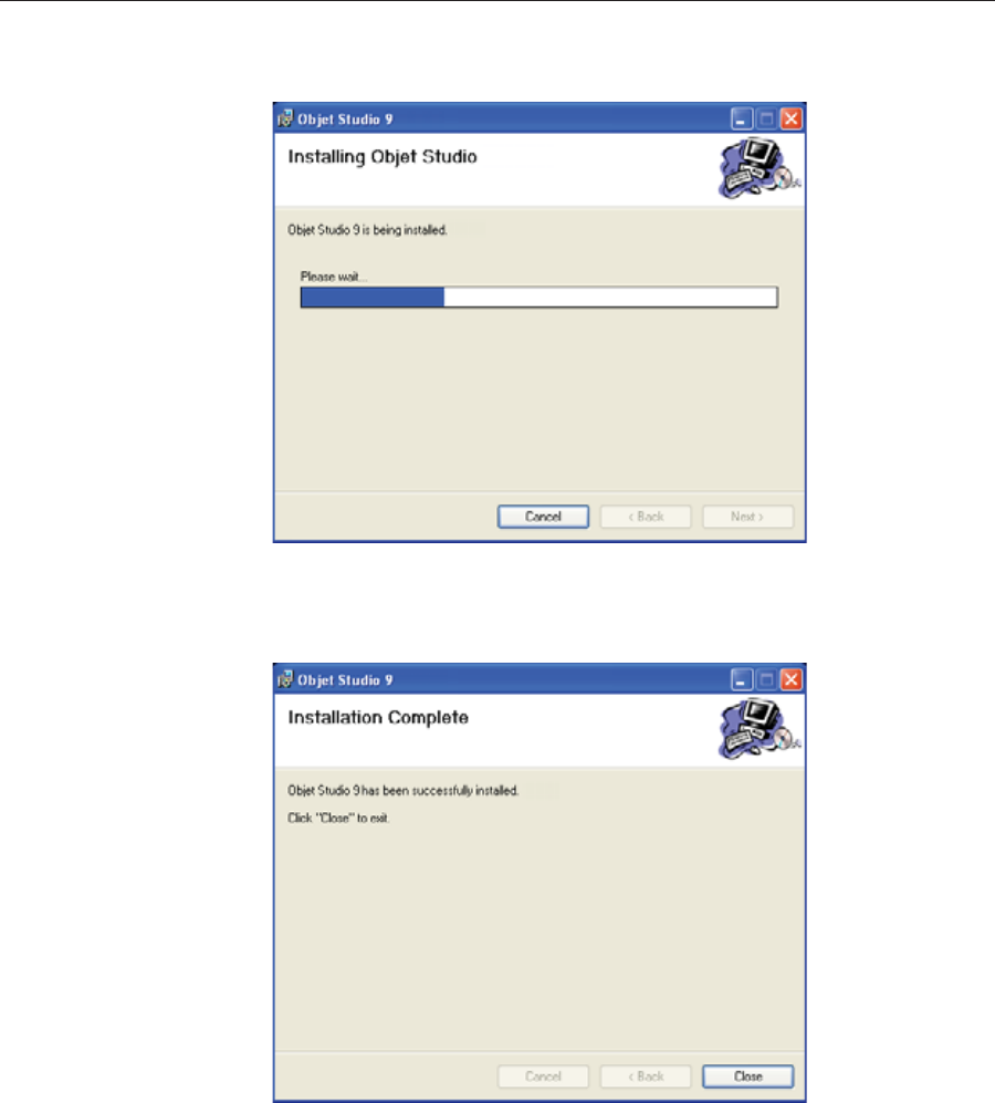
8. InȱtheȱSelectȱInstallationȱFolderȱscreen,ȱverifyȱtheȱdestinationȱfolderȱandȱ
clickȱNext.ȱ
Figure 4-4: Objet Studio installation-folder selection
9. InȱtheȱConfirmȱInstallationȱscreen,ȱclickȱNext toȱbeginȱinstallation.ȱ
10. InȱtheȱSelectȱPrinterȱTypeȱscreen,ȱselectȱtheȱObjetȱ3Dȱprinterȱusedȱforȱ
producingȱmodelsȱandȱclickȱNext.
Figure 4-5: Printer selection
It is recommended that you do not change the default destination folder.
Click Disk Space to check the space in the destination folder.
DOC08010 Rev. A (DRAFT 1) 4–5
Stratasys P750K User Guide
Installationȱbeginsȱandȱaȱprogressȱbarȱappears,ȱshowingȱtheȱprogressȱofȱ
theȱinstallationȱprocess.
Figure 4-6: Installation progress bar
WhenȱtheȱObjetȱprogramȱinstallationȱisȱcomplete,ȱtheȱfinalȱInstallShieldȱ
wizardȱscreenȱappears.
Figure 4-7: Final installation screen
11. Restartȱtheȱcomputerȱtoȱcompleteȱtheȱsoftwareȱinstallation.
Note: If you installed the software from a CD or DVD, make sure to remove
it from the disk drive before restarting the computer.
Theȱinstallationȱprocessȱendsȱwhenȱtheȱappropriateȱicon(s)ȱappearȱonȱtheȱ
computerȱdesktop:ȱ
•ObjetȱStudio
•StopȱJobȱManagerȱ(forȱserversȱandȱstandaloneȱstations)

Installing Objet Software
4–6 DOC08010 Rev. A (DRAFT 1)
How to Uninstall Objet Studio
IfȱthereȱisȱeverȱaȱneedȱtoȱuninstallȱtheȱObjetȱStudioȱsoftware,ȱdoȱnotȱattemptȱ
toȱdoȱsoȱfromȱtheȱWindowsȱControlȱPanel.ȱ(Thisȱdoesȱnotȱcompletelyȱ
removeȱallȱsoftwareȱcomponents.)ȱInstead—
¾FromȱtheȱStartȱmenu,ȱselectȱAll Programs > Objet Studio > Uninstall Objet
Studio.

DOC08010 Rev. A (DRAFT 1) 5–1
Using Objet Studio
LaunchingȱObjetȱStudio...................................................................... 3
Windows®ȱ7ȱSecurityȱWarning...........................................................3
ObjetȱStudioȱInterface...........................................................................4
RibbonȱCommands...............................................................................6
ObjetȱStudioȱCommandsȱMenu ..........................................................8
ModelȱTreeȱPane....................................................................................8
PreparingȱModelsȱforȱProduction..................................................... 9
OBJDFȱFiles:ȱOverview.........................................................................9
Model Files.............................................................................................9
PlacingȱObjectsȱonȱtheȱBuildȱTray.....................................................10
OpeningȱObjetȱTrayȱFiles ...................................................................14
QuickȬAccessȱModelȱCommands......................................................16
CopyingȱandȱPastingȱObjects ............................................................17
SelectingȱObjects..................................................................................18
SplittingȱObjectsȱintoȱComponents...................................................19
ModelȬMaterialȱSettings.....................................................................20
ChangingȱtheȱModelȱMaterial...........................................................21
AssigningȱaȱModelȱMaterialȱtoȱObjects............................................22
SurfaceȱFinish.......................................................................................23
CoatingȱObjects....................................................................................23
AssigningȱPropertiesȱtoȱHiddenȱObjects .........................................24
PositioningȱObjectsȱonȱtheȱBuildȱTray............................................ 25
AutomaticȱOrientation .......................................................................25
AutomaticȱPlacement .........................................................................26
ManualȱPositioning.............................................................................26
ModelȱOrientation............................................................................. 26
ManipulatingȱObjectsȱonȱtheȱBuildȱTray........................................ 27
PositioningȱObjectsȱonȱtheȱZȬAxis ....................................................27
ValidȱObjectȱPlacement.......................................................................28
UsingȱaȱGridȱtoȱPositionȱObjects.......................................................30
MeasurementȱUnits.............................................................................31
SettingȱModelȱDimensions.................................................................32
RepositioningȱObjects.........................................................................32
ChangingȱanȱObject’sȱOrientation.....................................................34
GroupingȱandȱUngroupingȱObjects..................................................36
FreezingȱModelȱOrientation ..............................................................37
DisplayȱOptions................................................................................. 37
ViewingȱObjects...................................................................................37
ScreenȱLayout ......................................................................................39
TrayȱPerspective ..................................................................................39
SettingȱObjectȱColors ..........................................................................41
LoadingȱLargeȱFiles ............................................................................41
LargeȱFileȱManipulation.....................................................................42
ZoomȱOptions......................................................................................44
5–2 DOC08010 Rev. A (DRAFT 1)
HandlingȱCompletedȱTrays ............................................................. 45
TrayȱValidation ....................................................................................45
ProductionȱEstimates..........................................................................46
PrintingȱModes....................................................................................47
EȬmailingȱObjetȱDigitalȱFiles .............................................................48
PrintingȱtheȱTrayȱFile..........................................................................48
ApplyingȱAdditionalȱObjetȱStudioȱFeatures................................. 51
DividingȱObjects..................................................................................51
ChoosingȱtheȱSupportȱStrength.........................................................52
“Hollow”—ȱFillingȱModelsȱwithȱSupportȱMaterial.......................53
DisplayingȱtheȱCrossȱSectionȱofȱObjects .......................................... 54
SavingȱtheȱScreenȱDisplayȱasȱanȱImage File....................................55
ExportingȱandȱImportingȱObjetȱBuildȱTrays...................................56
CustomizingȱObjetȱStudio................................................................ 57
CreatingȱaȱQuickȱAccessȱToolbar......................................................57
HidingȱtheȱRibbon...............................................................................58
DisplayȱColors.....................................................................................59
KeyboardȱShortcuts ............................................................................60
SettingȱUserȱPreferences.....................................................................61
ProfessionalȱModeȱFeatures............................................................. 62
DefaultȱSettings ...................................................................................63
OpenGLȱDriverȱConfiguration..........................................................64
GettingȱAdditionalȱObjetȱStudioȱAssistance ................................. 66
ObjetȱStudioȱVersion,ȱMaterialȱModuleȱandȱLicensedȱFeatures. 66
MonitoringȱandȱManagingȱPrintȱJobs ............................................ 68
JobȱManagerȱScreen ............................................................................68
SettingȱtheȱPrinterȱConnection..........................................................70
OffȬlineȱMode.......................................................................................71
SettingȱtheȱRemoteȱPrinterȱConnectionȱ(ClientȱMode)..................73
JobȱManagerȱCommands ...................................................................73
ConfiguringȱUserȱAlerts.....................................................................76
PrintingȱtheȱTray..................................................................................77
AdditionalȱServerȱFeatures................................................................77
DOC08010 Rev. A (DRAFT 1) 5–3
Stratasys P750K User Guide
Launching Objet Studio
AfterȱyouȱinstallȱObjetȱStudio,ȱaȱlaunchȱiconȱȱappearsȱonȱtheȱ
Windowsȱdesktop.ȱOpenȱtheȱapplicationȱbyȱdoubleȬclickingȱthisȱicon,ȱorȱbyȱ
selectingȱObjetȱStudioȱfromȱtheȱStartȱmenu.
Windows® 7
Security
Warning
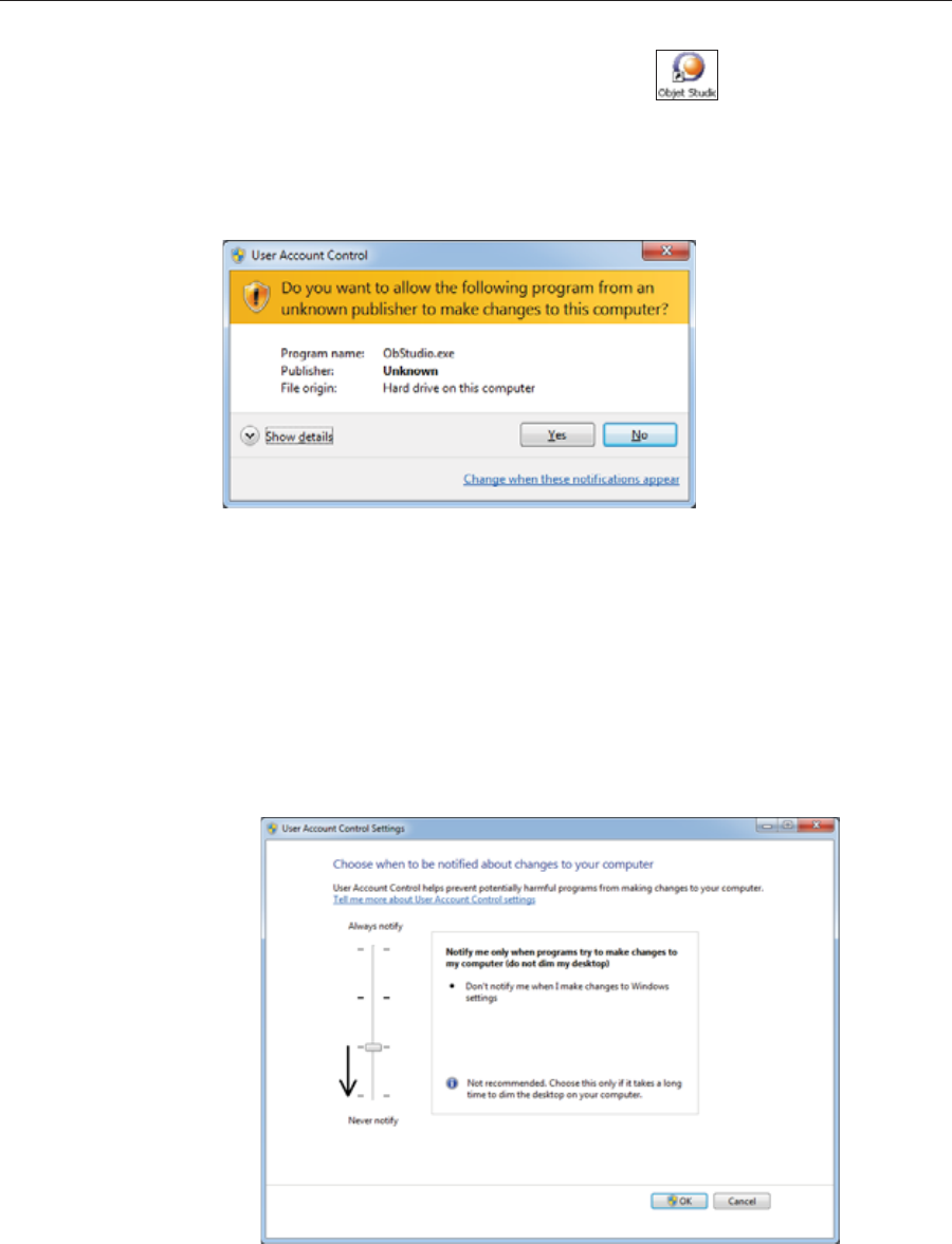
DependingȱonȱtheȱUserȱAccountȱControlȱsettingsȱinȱWindows®ȱ7,ȱyouȱ
mightȱseeȱtheȱfollowingȱwarningȱwhenȱopeningȱObjetȱStudio.
Figure 5-1: Security Warning
IfȱyouȱclickȱYes,ȱObjetȱStudioȱopens.ȱHowever,ȱthisȱwarningȱmessageȱwillȱ
appearȱeachȱtimeȱyouȱopenȱtheȱprogram,ȱunlessȱyouȱchangeȱtheȱUserȱ
AccountȱControlȱsettings.
To prevent the warning message from appearing again:
1. Clickȱtheȱlinkȱatȱtheȱbottomȱofȱtheȱsecurityȱwarningȱdialogȱboxȱ(Change
when these notifications appear).
2. InȱtheȱUserȱAccountȱControlȱSettingsȱscreen,ȱmoveȱtheȱsliderȱtoȱ“Neverȱ
notify.”
Figure 5-2: Changing the User Account Control settings
3. ClickȱOK.
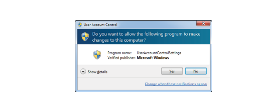
Using Objet Studio
5–4 DOC08010 Rev. A (DRAFT 1)
4. Inȱtheȱfollowingȱdialogȱbox,ȱclickȱYes.
Figure 5-3: Confirming the change in the User Account Control settings
Objet Studio
Interface WhenȱObjetȱStudioȱopens,ȱtheȱTrayȱSettingsȱscreenȱappears,ȱshowingȱanȱ
emptyȱbuildȱtray.ȱ
Figure 5-4: Objet Studio opening screen
TheȱObjetȱStudioȱinterfaceȱconsistsȱofȱtwoȱmainȱscreens:
•TrayȱSettings—forȱarrangingȱmodelsȱandȱpreparingȱthemȱforȱprinting.
•JobȱManager—forȱmonitoringȱandȱmanagingȱprintȱjobs.
Thisȱscreenȱisȱdescribedȱinȱ“MonitoringȱandȱManagingȱPrintȱJobs”ȱonȱ
page 68.
Eachȱscreenȱisȱcontrolledȱbyȱmenusȱandȱiconsȱonȱitsȱownȱribbon.ȱAnȱ
additionalȱribbon,ȱModelȱSettings,ȱdisplaysȱcontrolsȱforȱconfiguringȱandȱ
manipulatingȱselectedȱmodels.
ObjetȱStudioȱanticipatesȱyourȱworkflowȱbyȱdisplayingȱandȱenablingȱtheȱ
optionsȱrelevantȱtoȱyourȱcurrentȱtask.ȱForȱexample,ȱwhenȱyouȱfirstȱopenȱ
ObjetȱStudio,ȱtheȱModelȱSettingsȱribbonȱisȱdisabledȱuntilȱyouȱplaceȱaȱmodelȱ
onȱtheȱbuildȱtray.ȱSimilarly,ȱoptionsȱavailableȱfromȱtheȱstandardȱtoolbarȱ
menusȱareȱenabledȱorȱdisabledȱtoȱmatchȱtheȱcurrentȱworkflow.

DOC08010 Rev. A (DRAFT 1) 5–5
Stratasys P750K User Guide
Theȱribbon,ȱcolorsȱused,ȱandȱseveralȱotherȱinterfaceȱfeaturesȱcanȱbeȱ
customized.ȱHowȱtoȱchangeȱtheȱappearanceȱofȱtheȱinterfaceȱisȱexplainedȱinȱ
“CustomizingȱObjetȱStudio”ȱonȱpage 57.
Figure 5-5: Tray Settings ribbon
Figure 5-6: Model Settings ribbon
Instructions for using the commands for preparing models for production
and sending jobs to the printer, appear later in this chapter.
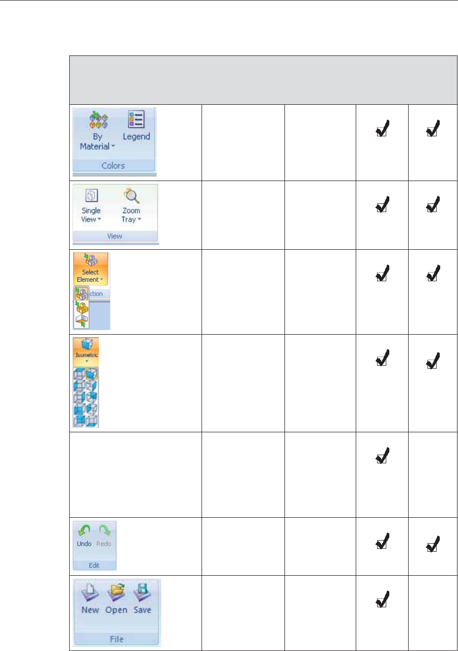
Using Objet Studio
5–6 DOC08010 Rev. A (DRAFT 1)
Ribbon
Commands TheȱfollowingȱtableȱlistsȱtheȱTrayȱSettingsȱandȱModelȱSettingsȱribbonȱ
commandȱgroups,ȱandȱshowsȱwhenȱtheyȱareȱenabled,ȱandȱwhereȱtheyȱ
appear.ȱ
Group Purpose When
enabled Tray
Settings
Ribbon
Model
Settings
Ribbon
Settingȱdisplayȱ
colors. Always.
Selectingȱ
perspectiveȱandȱ
zoomȱlevel.
Modelsȱareȱonȱ
theȱbuildȱtray.
Chooseȱtoȱselectȱ
aȱplane,ȱ
elements,ȱorȱ
elementȱgroupsȱ
(assemblies).
Modelsȱareȱonȱ
theȱbuildȱtray.
Changeȱtheȱ
perspectiveȱofȱ
theȱactiveȱpane.
Modelsȱareȱonȱ
theȱbuildȱtray.
Assigningȱ
printingȱ
material(s).
•Buildȱtrayȱ
isȱempty.
•Modelsȱareȱ
notȱ
selected.
Undoingȱorȱ
redoingȱactions. Afterȱanȱ
actionȱorȱ
objectȱ
selection.
Openingȱandȱ
savingȱfiles. Modelsȱareȱ
notȱselected.
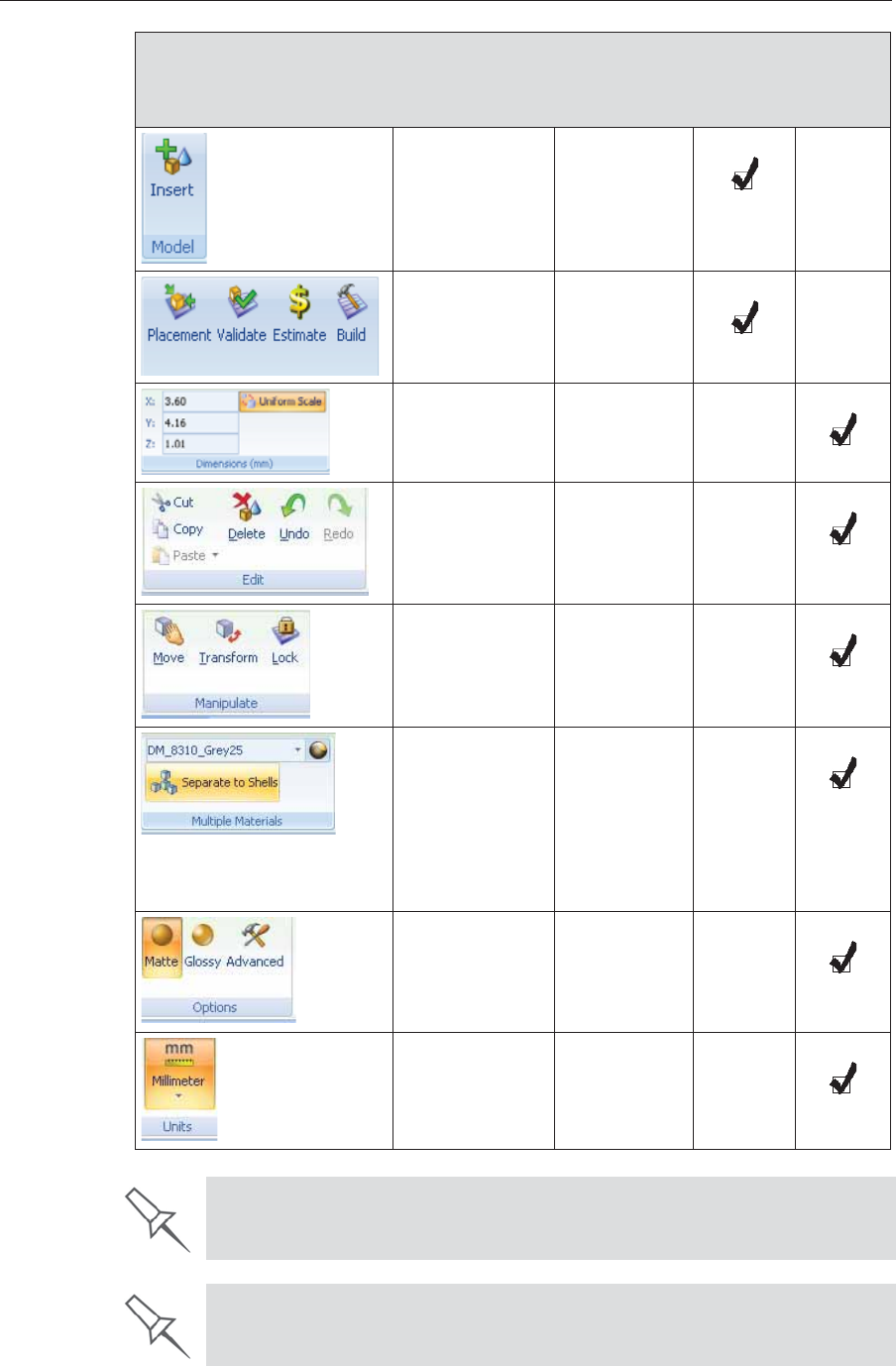
DOC08010 Rev. A (DRAFT 1) 5–7
Stratasys P750K User Guide
Placingȱmodelȱ
filesȱonȱtheȱbuildȱ
tray.
Always.
PreȬbuild/buildȱ
commands. Modelsȱareȱonȱ
theȱbuildȱtray.
ȱ
Settingȱmodelȱ
dimensions. Aȱmodelȱisȱ
selected.
Cutting,ȱ
copying,ȱpastingȱ
andȱdeletingȱ
models.
Aȱmodelȱisȱ
selected.
Moving,ȱrotatingȱ
andȱresizingȱ
models.
Aȱmodelȱisȱ
selected.
•Assigningȱaȱ
materialȱtoȱaȱ
modelȱorȱ
shell.
•Separatingȱaȱ
modelȱintoȱ
shells.
Aȱmodelȱisȱ
selected.
Assigningȱmodelȱ
finishȱandȱ
settingȱsupportȱ
strength/
“hollow.”
Aȱmodelȱisȱ
selected.
Settingȱaȱmodel’sȱ
unitȱofȱmeasureȱ
(millimetersȱorȱ
inches).
Aȱmodelȱisȱ
selected.
Group Purpose When
enabled Tray
Settings
Ribbon
Model
Settings
Ribbon
To quickly identify an icon, move the cursor over it to display a tooltip. The
“Undo” and “Redo” tooltips change to reflect your last Objet Studio action.
After activating some of the ribbon commands (by clicking them), they remain
active until you click another button or until you press the Escape key.
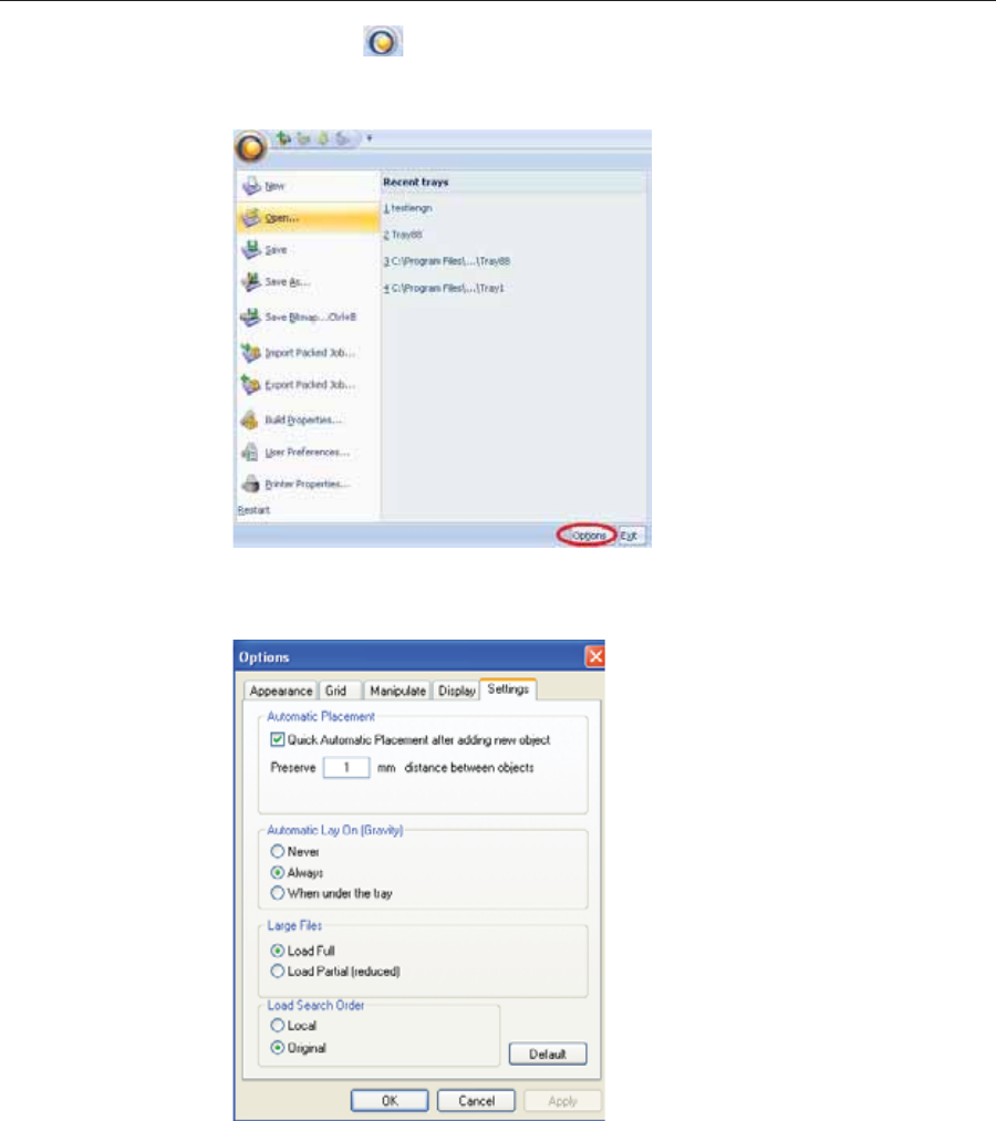
Using Objet Studio
5–8 DOC08010 Rev. A (DRAFT 1)
Objet Studio
Commands
Menu
ClickingȱtheȱȱiconȱinȱtheȱupperȬleftȱcornerȱopensȱtheȱObjetȱStudioȱ
Commandsȱmenu.ȱThisȱmenuȱdisplaysȱbasicȱapplicationȱcommandsȱandȱ
options.
Figure 5-7: Objet Studio Commands menu
TheȱOptions buttonȱopensȱaȱdialogȱboxȱforȱcustomizingȱObjetȱStudio.
Figure 5-8: Options dialog box
Model Tree
Pane TheȱModelȱTreeȱpaneȱlistsȱtheȱobjectsȱplacedȱonȱtheȱbuildȱtrayȱinȱaȱparentȬ
childȱhierarchy.ȱByȱdefault,ȱtheȱpaneȱ“floats”—ȱthatȱis,ȱyouȱcanȱmoveȱitȱtoȱ
anotherȱpositionȱonȱtheȱscreenȱandȱresizeȱit.ȱAlternatively,ȱyouȱcanȱfixȱitsȱ
positionȱatȱtheȱleftȱofȱtheȱapplicationȱwindow,ȱandȱevenȱhideȱit.

DOC08010 Rev. A (DRAFT 1) 5–9
Stratasys P750K User Guide
Preparing Models for Production
Modelȱpreparationȱinvolvesȱtheȱfollowingȱbasicȱsteps:
1. Placeȱobjectsȱorȱassembliesȱonȱtheȱbuildȱtray.
2. Ifȱnecessary,ȱmanipulateȱtheȱobject’sȱorientationȱandȱposition.
3. Selectȱtheȱmaterialsȱandȱmodelȱfinish.
JustȱasȱStratasysȱprintersȱcanȱproduceȱdifferentȱmodelsȱonȱtheȱbuildȱtrayȱ
usingȱdifferentȱmaterials,ȱyouȱcanȱproduceȱcomponentsȱofȱaȱmodelȱwithȱ
differentȱmaterials.ȱToȱdoȱthis,ȱeachȱpartȱofȱtheȱmodelȱmustȱbeȱaȱseparateȱstlȱ
file.ȱIfȱtheȱmodel’sȱcomponentȱpartsȱwereȱnotȱsavedȱinȱtheȱCADȱsoftwareȱasȱ
separateȱstlȱfiles,ȱyouȱcanȱuseȱObjetȱStudioȱtoȱseparateȱtheȱmodelȱintoȱ
componentȱparts.ȱ(Thisȱisȱdescribedȱinȱ“SplittingȱObjectsȱintoȱComponents”ȱ
onȱpage 19ȱandȱinȱ“DividingȱObjects”ȱonȱpage 51.)
OBJDF Files:
Overview Anȱobjdfȱfileȱdescribesȱbothȱtheȱgeometryȱofȱaȱsingleȱobjectȱandȱtheȱ
materials,ȱandȱfinishȱrequiredȱtoȱprintȱit.ȱTheȱobjdfȱfileȱcanȱrepresentȱanȱ
objectȱthatȱisȱaȱsingleȱstlȱfile,ȱorȱanȱobjectȱassembledȱfromȱcomponentȱstlȱ
files.ȱ
ObjetȱStudioȱenablesȱyouȱtoȱsplitȱanȱstlȱfileȱrepresentingȱaȱcomplexȱobjectȱ
intoȱanȱassemblyȱofȱcomponentȱstlȱfiles,ȱandȱsaveȱtheȱassemblyȱasȱanȱobjdfȱ
file.ȱEachȱpartȱ(stlȱfile)ȱdescribedȱbyȱtheȱobjdfȱfileȱcanȱhaveȱitsȱownȱmodelȬ
materialȱcharacteristic,ȱsoȱthatȱtheȱStratasysȱprinterȱproducesȱtheȱ
componentȱpartsȱfromȱspecificȱmaterials.ȱ
Anotherȱuseȱforȱobjdfȱfilesȱisȱforȱsavingȱaȱgroupȱofȱseparateȱobjectsȱonȱtheȱ
buildȱtrayȱasȱoneȱunit,ȱtogetherȱwithȱtheirȱrelativeȱpositionsȱandȱmaterials.ȱ
Thisȱisȱespeciallyȱusefulȱforȱproducingȱmodelsȱinȱtheȱfutureȱwithȱtheȱsameȱ
materials.ȱInȱfact,ȱwhenȱyouȱsaveȱobjdfȱfiles,ȱyouȱspecifyȱmaterialsȱforȱ
printingȱmodelsȱwithoutȱregardȱtoȱtheȱmaterialȱcartridgesȱloadedȱinȱtheȱ
printer.ȱTheȱsameȱobjectȱcanȱlaterȱbeȱplacedȱonȱbuildȱtraysȱforȱprinting.ȱEachȱ
timeȱyouȱsendȱaȱbuildȱtrayȱtoȱtheȱprinter,ȱyouȱdecideȱwhetherȱtoȱallowȱ
printingȱwithȱsubstituteȱmaterialsȱorȱonlyȱwithȱtheȱmaterialsȱspecified.
TheȱConnexȱversionȱofȱObjetȱStudioȱenablesȱyouȱtoȱdisplay,ȱmanipulateȱandȱ
printȱcomponentȱpartsȱofȱaȱmodelȱassemblyȱthatȱwasȱsavedȱasȱanȱobjdfȱfile,ȱ
sinceȱeachȱcomponentȱisȱaȱseparateȱstlȱfile.ȱThisȱcanȱbeȱusefulȱforȱprintingȱ
onlyȱspecificȱpartsȱofȱaȱmodel.
Furtherȱexplanationsȱofȱobjdfȱfiles,ȱandȱtheirȱfeatures,ȱappearȱthroughoutȱ
thisȱchapter.
Model Files Toȱproduceȱmodels,ȱyouȱopenȱoneȱorȱmoreȱmodelȱfilesȱinȱObjetȱStudioȱandȱ
positionȱobjectsȱonȱtheȱbuildȱtray.ȱYouȱcanȱplaceȱobjectsȱonȱtheȱbuildȱtrayȱinȱ
severalȱways:
•byȱinsertingȱindividual stl or slc filesȱ(orȱanȱassemblyȱofȱstlȱfiles).
•byȱinserting anȱobjdfȱfileȱ(anȱassembly).
•byȱpastingȱobjectsȱthatȱyouȱcopiedȱtoȱtheȱWindowsȱclipboard.
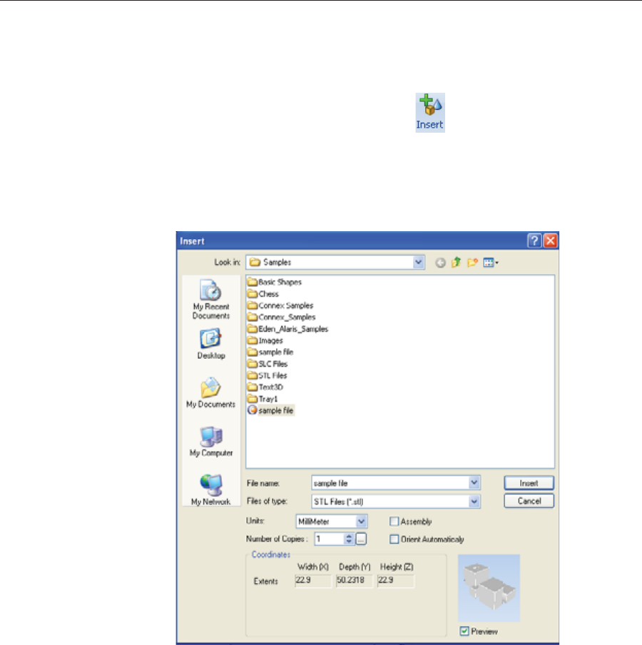
Using Objet Studio
5–10 DOC08010 Rev. A (DRAFT 1)
Placing
Objects on the
Build Tray
To place an object on the build tray:
1. OpenȱtheȱInsertȱdialogȱbox—
•FromȱtheȱObjectȱmenu,ȱselectȱInsert.
or—
•OnȱtheȱTrayȱSettingsȱribbon,ȱclickȱ.
or—
•RightȬclickȱonȱtheȱbuildȱtray,ȱandȱselectȱInsert fromȱtheȱcontextȱ
menu.
TheȱInsertȱdialogȱboxȱappears.
Figure 5-9: Insert dialog box
2. InȱtheȱLookȱinȱfield,ȱdisplayȱtheȱappropriateȱfolder.
3. InȱtheȱFilesȱofȱtypeȱfield,ȱselectȱtheȱfileȱtypeȱtoȱdisplay.
4. Selectȱtheȱdesiredȱfile,ȱandȱmakeȱsureȱthatȱitȱappearsȱinȱtheȱFileȱnameȱ
field.
IfȱtheȱPreviewȱcheckȱboxȱisȱselected,ȱtheȱobjectȱisȱdisplayedȱinȱtheȱdialogȱ
box,ȱasȱshownȱinȱfigure 5Ȭ9.
Youȱcanȱopenȱseveralȱstlȱfilesȱtoȱplaceȱseveralȱmodelsȱonȱtheȱbuildȱtray.ȱ
Ifȱyouȱselectȱmultipleȱstlȱfilesȱthatȱmakeȱupȱanȱassembly,ȱyouȱcanȱselectȱ
allȱorȱsomeȱofȱtheȱparts.ȱToȱprintȱtheȱentireȱmodel,ȱselectȱallȱofȱanȱ
assembly’sȱcomponentȱstlȱfiles,ȱandȱselectȱtheȱAssemblyȱcheckȱbox.ȱThisȱ
positionsȱtheȱpartsȱasȱaȱcomplete,ȱintegratedȱmodelȱinsteadȱofȱasȱ
independentȱparts.ȱTheȱeffectsȱofȱselectingȱtheȱAssemblyȱcheckȱbox—inȱ
bothȱtheȱmodelȱtreeȱandȱtheȱbuildȱtrayȱdisplay—areȱshownȱinȱtheȱ
followingȱfigures.
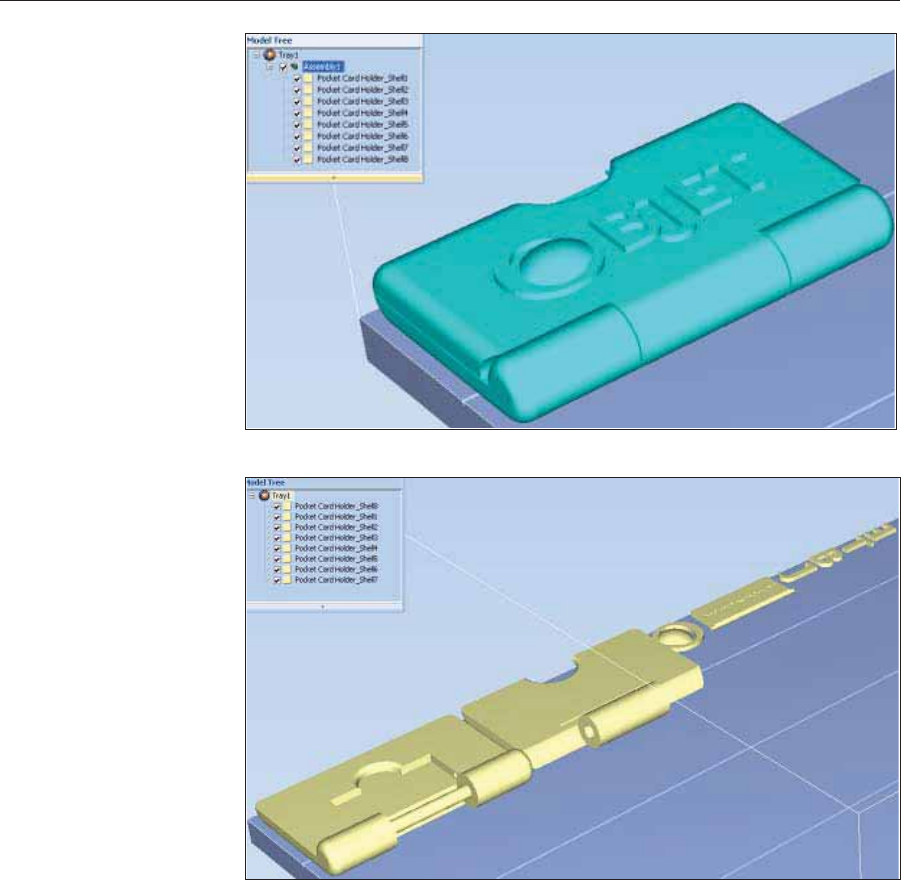
DOC08010 Rev. A (DRAFT 1) 5–11
Stratasys P750K User Guide
Figure 5-10: Assembly check box selected—stl files are placed as an assembly
Figure 5-11: Assembly check box not selected—stl files are placed as parts
TheȱModelȱSettingsȱribbonȱisȱdisplayedȱwhenȱobjectsȱareȱplacedȱonȱtheȱ
buildȱtray.
5. Selectȱanyȱofȱtheȱfollowingȱoptions,ȱasȱrequired:
•Units—Millimetersȱorȱinchesȱforȱtheȱobject’sȱunitsȱofȱmeasure.
Theȱ3Dȱfileȱcontainsȱtheȱobjectȇsȱproportions,ȱbutȱnotȱitsȱunitsȱofȱ
measure.ȱTherefore,ȱmakeȱsureȱtoȱcorrectlyȱselectȱeitherȱmillimetersȱ
orȱinchesȱwhenȱinsertingȱanȱobject.ȱOtherwise,ȱtheȱsizeȱofȱtheȱobjectȱ
onȱtheȱbuildȱtrayȱwillȱbeȱeitherȱmuchȱtooȱlargeȱorȱmuchȱtooȱsmall.ȱToȱ
changeȱtheȱmeasurementȱunitsȱofȱobjectsȱalreadyȱplacedȱonȱtheȱtray,ȱ
seeȱ“MeasurementȱUnits”ȱonȱpage 31.
•Number of copies—Howȱmanyȱcopiesȱofȱthisȱobjectȱtoȱplaceȱonȱtheȱ
buildȱtray.
•Orient Automatically—Automaticallyȱorientȱobjectsȱonȱtheȱbuildȱtrayȱ
forȱefficientȱmodelȱbuilding.
•Assembly—Markȱthisȱcheckȱboxȱifȱyouȱselectedȱmultipleȱstlȱfilesȱthatȱ
areȱpartȱofȱanȱassembly.
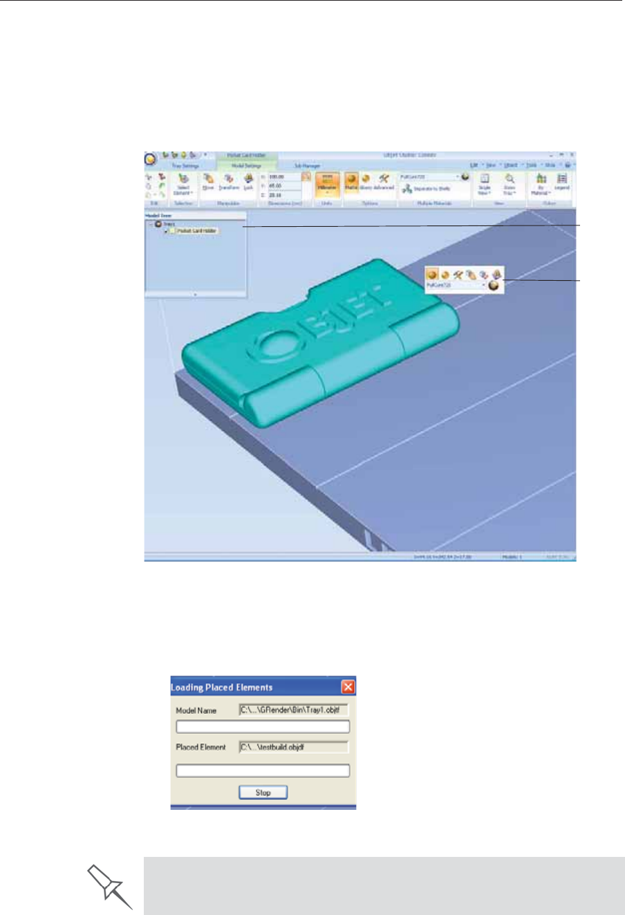
Using Objet Studio
5–12 DOC08010 Rev. A (DRAFT 1)
Note: The Extents values displayed in the Coordinates section of the Insert
dialog box, represent the maximum dimensions of the object on each
axis. These dimensions correspond to the virtual “bounding box”
surrounding the object see figure 5-50 on page 38).
6. ClickȱInsert.
ObjetȱStudioȱplacesȱtheȱobjectȱonȱtheȱbuildȱtray,ȱandȱinȱtheȱmodelȱtree.
Figure 5-12: Default screen layout
TheȱModelȱSettingsȱribbonȱisȱdisplayedȱwhenȱobjectsȱareȱplacedȱonȱtheȱ
buildȱtray.
Ifȱtheȱobjectȱisȱoverȱaȱcertainȱsize,ȱtheȱLoadingȱPlacedȱElementsȱdialogȱboxȱ
appears.
ȱ
Figure 5-13: Loading Placed Elements dialog box
Model
Toolbar
Model
Tree
pane
You can speed up the opening of large files by changing the Large Files
settings—see “Loading Large Files” on page 41).
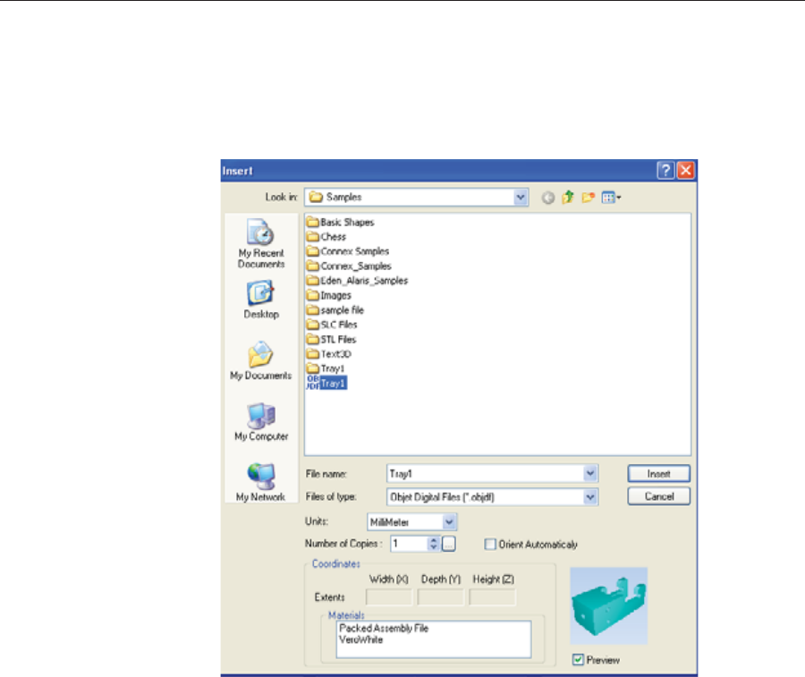
DOC08010 Rev. A (DRAFT 1) 5–13
Stratasys P750K User Guide
OpeningȱobjdfȱFiles
Beforeȱplacingȱobjdfȱfilesȱonȱtheȱbuildȱtray,ȱObjetȱStudioȱmustȱextractȱtheȱ
componentȱstlȱfilesȱtogetherȱwithȱinformationȱaboutȱtheirȱrelativeȱpositionȱ
andȱmodelȱmaterials.ȱToȱdoȱthis,ȱObjetȱStudioȱcreatesȱaȱfolderȱwithȱtheȱsameȱ
nameȱasȱtheȱobjdfȱfile,ȱinȱtheȱsameȱlocation.
Figure 5-14: Insert dialog box (objdf file)
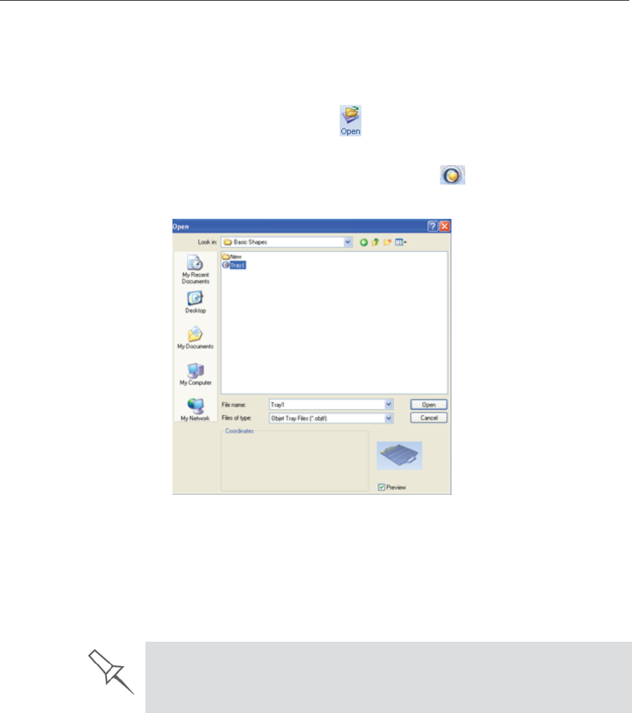
Using Objet Studio
5–14 DOC08010 Rev. A (DRAFT 1)
Opening Objet
Tray Files Youȱcanȱopenȱtraysȱthatȱwereȱsavedȱasȱobjtfȱfiles.ȱThisȱisȱuseful,ȱforȱexample,ȱ
ifȱyouȱsavedȱaȱtrayȱafterȱpreparingȱitȱforȱprinting,ȱandȱnowȱyouȱwantȱtoȱ
makeȱchangesȱbeforeȱprintingȱit.ȱ
To place an object saved as an Objet Tray File (objtf) file on the build
tray:
1. FromȱtheȱFileȱgroup,ȱclickȱ.
or—
FromȱtheȱObjetȱStudioȱCommandsȱmenuȱ,ȱselectȱOpen.
TheȱOpenȱdialogȱboxȱisȱdisplayed.
Figure 5-15: Objet Tray File Open dialog box
2. Selectȱtheȱdesiredȱfile,ȱandȱmakeȱsureȱthatȱitȱappearsȱinȱtheȱFileȱnameȱ
field.ȱ
IfȱtheȱPreviewȱcheckȱboxȱisȱselected,ȱtheȱobjectȱisȱdisplayed.
3. ClickȱOpen.
ObjetȱStudioȱopensȱtheȱtrayȱfile.
The objtf file is actually a file containing instructions for printing—which stl
files to print and their position on the build tray. Because the objtf file
references the stl files used, they must remain in the same file location as
when the objtf file was saved.
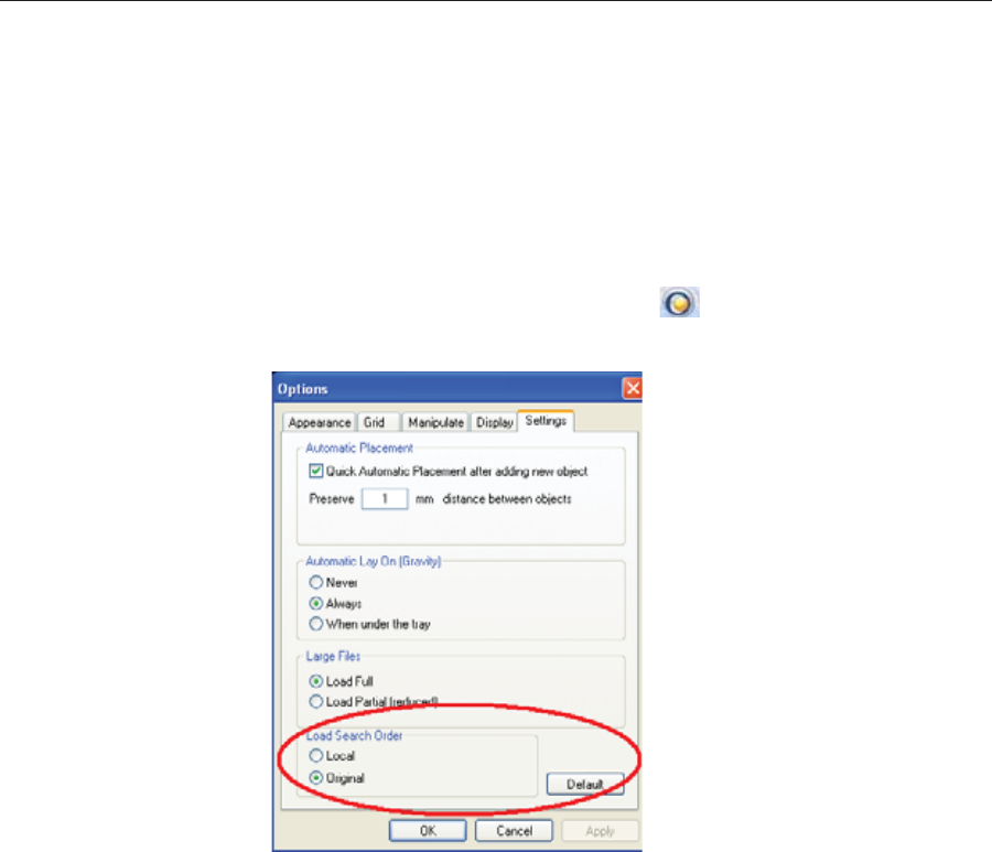
DOC08010 Rev. A (DRAFT 1) 5–15
Stratasys P750K User Guide
STL file loading
preference Ifȱthereȱareȱidenticallyȱnamedȱstlȱfilesȱinȱmoreȱthanȱoneȱlocation,ȱyouȱneedȱ
toȱensureȱthatȱtheȱcorrectȱcomponentȱstlȱfilesȱareȱlinkedȱtoȱtheȱobjtfȱfile.ȱForȱ
example,ȱifȱthereȱareȱidenticallyȱnamedȱstlȱfilesȱonȱoneȱdriveȱandȱonȱaȱflashȱ
driveȱ(thisȱcanȱoccurȱifȱyouȱcopyȱtheȱoriginalȱfilesȱtoȱaȱworkingȱfolder),ȱyouȱ
canȱsetȱtheȱdefaultȱlocationȱfromȱwhichȱfilesȱareȱloaded.
To set the Load Order:
1. FromȱtheȱToolsȱmenu,ȱselectȱOptions.
or—
InȱtheȱObjetȱStudioȱCommandsȱmenuȱ,ȱclickȱOptions.
2. InȱtheȱOptionsȱdialogȱbox,ȱdisplayȱtheȱSettingsȱtab.
Figure 5-16: Options dialog box, Settings tab
3. UnderȱLoadȱSearchȱOrder,ȱselectȱanȱoption:
•Local—toȱloadȱfilesȱfromȱtheȱlocationȱwhereȱtheyȱwereȱlastȱsaved.
•Original—toȱloadȱfilesȱinȱtheirȱoriginalȱlocation.
4. ClickȱOK.
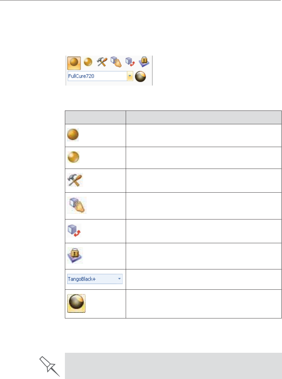
Using Objet Studio
5–16 DOC08010 Rev. A (DRAFT 1)
Quick-Access
Model
Commands
Youȱcanȱaccessȱcommonȱcommandsȱforȱworkingȱwithȱobjectsȱonȱtheȱbuildȱ
trayȱwithȱtheȱconvenientȱModelȱToolbarȱandȱcontextȱmenus.
Model Toolbar SelectȱanȱobjectȱinȱtheȱtrayȱtoȱdisplayȱtheȱModelȱToolbarȱthatȱcontainsȱiconsȱ
toȱperformȱcommonȱtasks.
Figure 5-17: Model Toolbar
TheȱtableȱbelowȱdescribesȱtheȱModelȱToolbarȱicons.
Right-click model
menu IfȱyouȱrightȬclickȱonȱanȱobject,ȱaȱpopȬupȱcontextȱmenuȱisȱdisplayedȱfromȱ
whichȱyouȱcanȱalsoȱselectȱtheȱmodelȱfinish,ȱchangeȱitsȱpositionȱandȱscale,ȱ
andȱsetȱtheȱGridȱStyleȱandȱHollowȱoptions.
Icon Description
Appliesȱaȱmatteȱfinishȱtoȱtheȱmodel.
Appliesȱaȱglossyȱfinishȱtoȱtheȱmodel.
OpensȱtheȱAdvancedȱPropertiesȱdialogȱboxȱforȱsettingȱtheȱ
GridȱStyleȱandȱtheȱHollowȱoption.
Enablesȱdraggingȱanȱobjectȱ(seeȱpage 5Ȭ32).
OpensȱtheȱTransformȱdialogȱboxȱforȱchangingȱtheȱ
object’sȱpositionȱandȱscale.
TogglesȱtheȱLockȱModelȱOrientationȱsetting.
Allowsȱyouȱtoȱchooseȱtheȱprintingȱmaterials.
Enablesȱyouȱtoȱapplyȱaȱcoatingȱtoȱtheȱmodel,ȱorȱchangeȱ
theȱcoatingȱpreviouslyȱapplied.
You can also create a Quick Access toolbar with your most commonly used
icons grouped together. See “Creating a Quick Access Toolbar” on page 57.
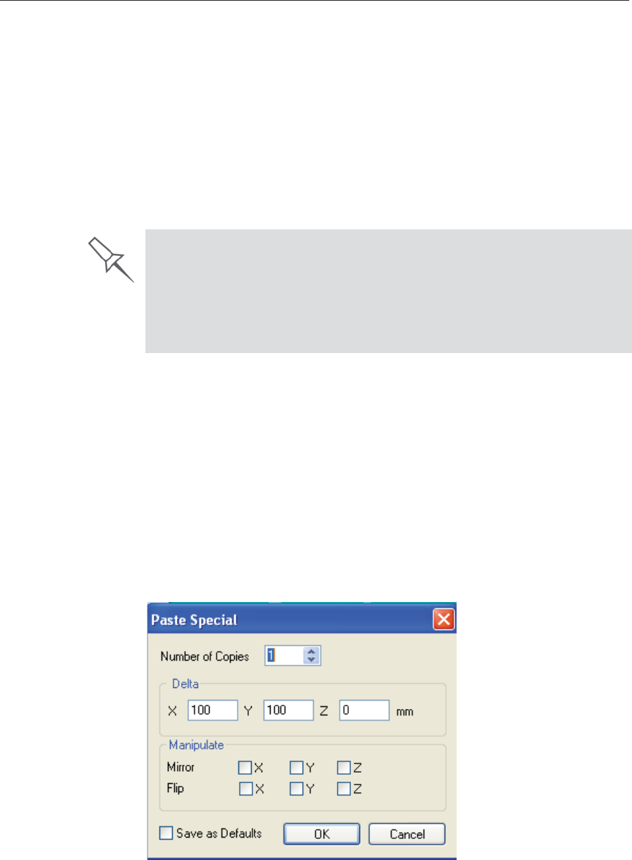
DOC08010 Rev. A (DRAFT 1) 5–17
Stratasys P750K User Guide
Copying and
Pasting
Objects
Ifȱyouȱneedȱtoȱduplicateȱobjectsȱonȱtheȱbuildȱtray,ȱyouȱcanȱinsertȱtheȱsameȱ
objectȱfromȱitsȱfileȱmoreȱthanȱonce.ȱAnȱeasierȱway,ȱhowever,ȱisȱtoȱcopyȱandȱ
pasteȱtheȱobject.ȱYouȱcanȱcopyȱobjectsȱfromȱtheȱbuildȱtrayȱorȱtheȱmodelȱ
tree—individualȱorȱmultipleȱpartsȱorȱassemblies.ȱTheȱobjectsȱcopiedȱremainȱ
inȱtheȱWindowsȱclipboardȱuntilȱyouȱpasteȱthemȱontoȱtheȱbuildȱtray.ȱ
Youȱcanȱalsoȱcopyȱobjectsȱfromȱoneȱtrayȱandȱpasteȱthemȱontoȱanother,ȱinȱtheȱ
sameȱwayȱasȱyouȱcopyȱtextȱfromȱoneȱdocumentȱandȱpasteȱitȱintoȱanotherȱ
one.ȱHowever,ȱObjetȱStudioȱallowsȱonlyȱoneȱtrayȱtoȱbeȱopenȱatȱaȱtime.ȱForȱ
eachȱbuildȱtrayȱyouȱneedȱtoȱworkȱwithȱ(atȱtheȱsameȱtime),ȱyouȱmustȱopenȱaȱ
separateȱObjetȱStudioȱwindow,ȱbyȱrunningȱtheȱapplicationȱagainȱ(fromȱtheȱ
WindowsȱStartȱmenu).
YouȱperformȱtheȱCopyȱandȱPasteȱcommandsȱasȱinȱotherȱWindowsȱ
applications:
•fromȱtheȱrightȬclickȱcontextȱmenu.
•byȱusingȱkeyboardȱshortcutsȱ(Ctrl+CȱandȱCtrl+V,ȱrespectively).
TheȱPasteȱSpecialȱcommandȱ(fromȱtheȱobject’sȱrightȬclickȱcontextȱmenu)ȱ
enablesȱyouȱtoȱplaceȱduplicateȱobjectsȱevenȱmoreȱefficiently:
•Youȱcanȱspecifyȱtheȱnumberȱofȱduplicatesȱtoȱplaceȱonȱtheȱbuildȱtrayȱatȱ
once.
•Youȱcanȱsetȱtheȱdistance,ȱonȱeachȱaxis,ȱbetweenȱtheȱduplicateȱobjects.
•Youȱcanȱmanipulateȱmirrorȱimagesȱofȱtheȱoriginalȱobject,ȱandȱflipȱthemȱ
onȱselectedȱaxes.
Figure 5-18: Paste Special dialog box
Having multiple Objet Studio windows open can be convenient when you
need to manipulate or configure objects before inserting them in your
production build tray. For example, if you need to change the model material
of an object (saved as an objdf file) to match the model material already
used in the production build tray, you must do so before inserting the
object—on another tray. Copying and pasting also allows you to use objects
already configured on previously-used build trays for newer projects.
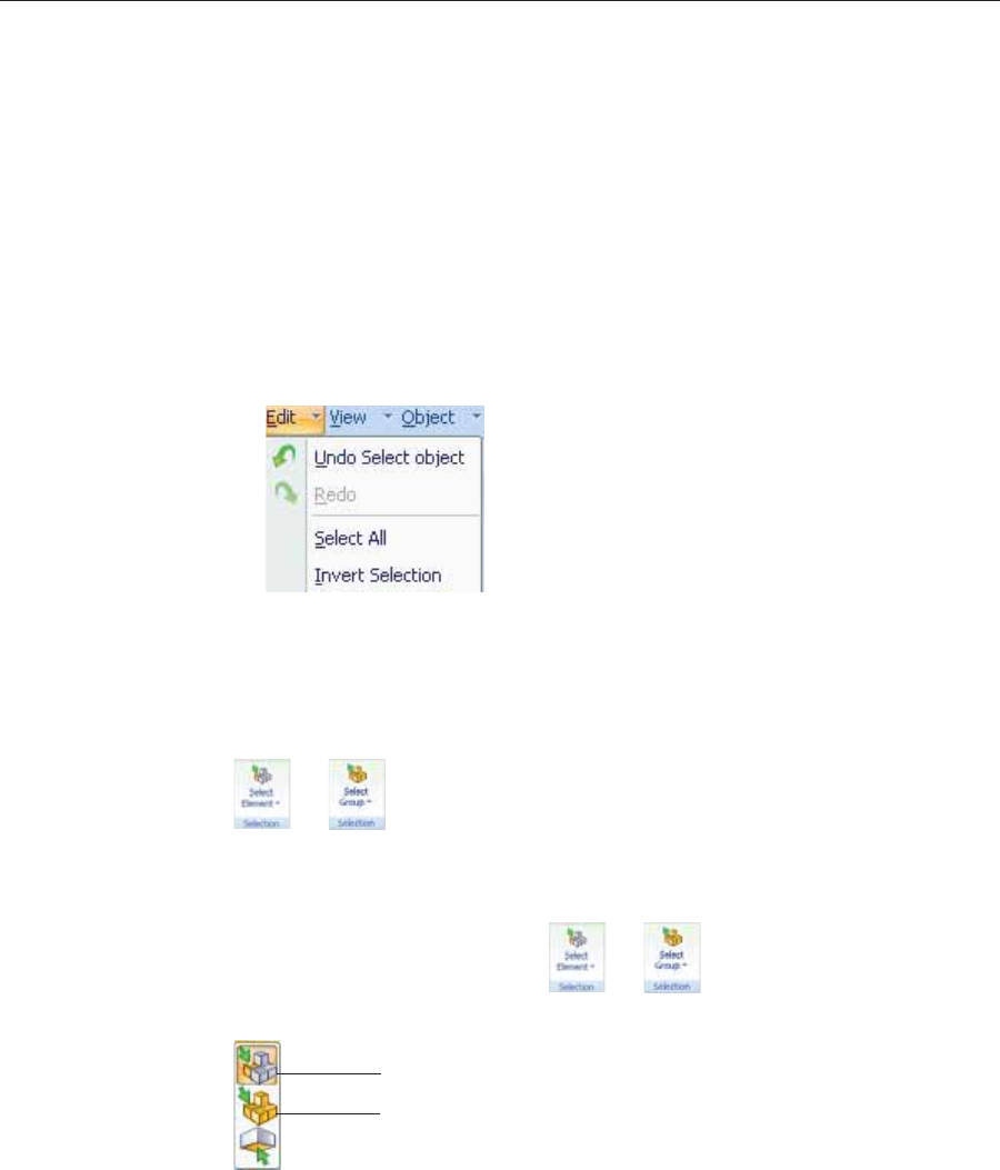
Using Objet Studio
5–18 DOC08010 Rev. A (DRAFT 1)
Selecting
Objects Toȱmanipulateȱanȱobjectȱonȱtheȱbuildȱtrayȱorȱassignȱcharacteristicsȱtoȱitȱ
(modelȱmaterial,ȱbuildingȱstyleȱetc.),ȱyouȱmustȱfirstȱselectȱtheȱobject.ȱYouȱ
selectȱanȱobjectȱbyȱclickingȱit,ȱeitherȱonȱtheȱtrayȱorȱinȱtheȱmodelȱtree.ȱItsȱ
imageȱonȱtheȱbuildȱtrayȱchangesȱcolorȱ(toȱlightȱblue,ȱbyȱdefault)ȱandȱitsȱ
nameȱisȱhighlightedȱinȱtheȱmodelȱtree.ȱYouȱcanȱselectȱmultipleȱobjectsȱbyȱ
drawingȱaȱboxȱaroundȱthemȱwithȱtheȱmouseȱcursor,ȱorȱbyȱpressingȱtheȱCtrlȱ
orȱShiftȱkeysȱwhileȱclickingȱadditionalȱobjects.
Alternatively,ȱselectȱorȱdeȬselectȱobjectsȱusingȱtheȱfollowingȱEditȱmenuȱ
commands:
•Select All
•Invert Selection
•Undo Select object
Figure 5-19: Edit menu
Sometimes,ȱyouȱneedȱtoȱselectȱindividualȱelementsȱofȱanȱassembly.ȱOtherȱ
times,ȱyouȱneedȱtoȱselectȱtheȱentireȱassembly.ȱTheȱSelectionȱiconȱdisplayedȱ
onȱtheȱribbonȱdeterminesȱwhatȱwillȱbeȱselectedȱwhenȱyouȱclickȱonȱtheȱ
model:
ȱorȱ
To change the selection action:
1. OnȱtheȱTrayȱSettingsȱorȱModelȱSettingsȱribbon—
a. ClickȱtheȱSelectionȱicon:ȱȱorȱ.
b. Onȱtheȱflyoutȱtoolbar,ȱclickȱtheȱappropriateȱicon:
Figure 5-20: Selection flyout toolbar
Select Group
Select Element
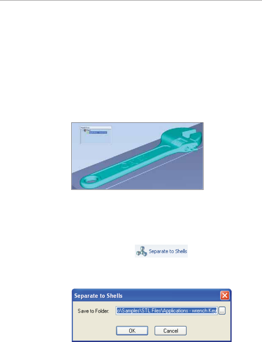
DOC08010 Rev. A (DRAFT 1) 5–19
Stratasys P750K User Guide
Splitting
Objects into
Components
Youȱcanȱconvertȱaȱcomplexȱobjectȱtoȱanȱassemblyȱofȱcomponentȱparts.ȱToȱdoȱ
so,ȱyouȱsplitȱtheȱstlȱfileȱthatȱrepresentsȱtheȱobjectȱintoȱaȱgroupȱofȱseparateȱstlȱ
files,ȱeachȱoneȱrepresentingȱaȱcomponent.ȱ(ThisȱisȱreferredȱtoȱinȱtheȱObjetȱ
Studioȱinterfaceȱasȱseparatingȱtheȱobjectȱintoȱshells.)ȱYouȱcanȱthenȱassignȱaȱ
modelȱmaterialȱtoȱeachȱstlȱfile,ȱandȱyouȱcanȱsaveȱtheȱnewlyȬcreatedȱ
assemblyȱasȱanȱobjdfȱfile.
To split an object into an assembly of component parts:
1. Ifȱtheȱobjectȱisȱnotȱdisplayed,ȱplaceȱitȱonȱtheȱbuildȱtrayȱbyȱinsertingȱitsȱstlȱ
fileȱ(seeȱ“PlacingȱObjectsȱonȱtheȱBuildȱTray”ȱonȱpage 10).
Theȱobjectȱappears—onȱtheȱbuildȱtrayȱandȱinȱtheȱmodelȱtreeȱpane—asȱaȱ
singleȱpart.ȱItȱisȱassigned,ȱbyȱdefault,ȱtheȱ“primary”ȱmodelȱmaterial.ȱ(Ifȱ
ObjetȱStudioȱisȱconfiguredȱwithȱaȱsecondaryȱmaterial,ȱyouȱcanȱassignȱ
it—orȱaȱdigitalȱmaterial—toȱtheȱentireȱobject.ȱThisȱisȱexplainedȱinȱ
“ModelȬMaterialȱSettings”ȱonȱpage 20.)
Figure 5-21: Object placed on the build tray from a single stl file
Note: There is no need to resize or arrange the object on the build tray at
this time.
2. Withȱtheȱobjectȱselected:
•FromȱtheȱObjectȱmenu,ȱselectȱSeparate into Shells.
or—
•Onȱtheȱribbon,ȱclickȱ.
Aȱdialogȱboxȱopensȱinȱwhichȱyouȱcanȱspecifyȱwhereȱtoȱsaveȱtheȱ
componentȱstlȱfiles.ȱ(Byȱdefault,ȱObjetȱStudioȱoffersȱtoȱsaveȱtheȱnewȱfilesȱ
inȱaȱfolderȱinȱtheȱsameȱlocationȱasȱtheȱoriginalȱstlȱfile.)
Figure 5-22: Folder selection for saving stl files after splitting into shells
3. ClickȱOK.
ObjetȱStudioȱsplitsȱtheȱobjectȱintoȱanȱassemblyȱofȱcomponentȱparts,ȱeachȱ
aȱseparateȱstlȱfileȱ(“shell”).
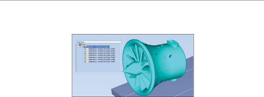
Using Objet Studio
5–20 DOC08010 Rev. A (DRAFT 1)
Theȱobjectȱappears—onȱtheȱbuildȱtrayȱandȱinȱtheȱmodelȱtree—asȱanȱ
assemblyȱofȱpartsȱ(“shells”).ȱYouȱcanȱassignȱeachȱpartȱaȱdifferentȱmodelȱ
materialȱ(Thisȱisȱexplainedȱinȱ“ModelȬMaterialȱSettings”ȱonȱpage 20).ȱ
Figure 5-23: Object after being converted to an assembly of component parts
Model-Material
Settings BeforeȱplacingȱobjectsȱonȱtheȱbuildȱtrayȱinȱObjetȱStudio,ȱyouȱshouldȱpayȱ
attentionȱtoȱtheȱmaterialȱselectionȱsettingsȱonȱtheȱTrayȱSettingsȱribbon.
Figure 5-24: Material selection settings
•Byȱdefault,ȱtheȱmaterialȱselectionȱsettingsȱonȱtheȱribbonȱcorrespondȱtoȱ
theȱmodelȱcartridgesȱloadedȱinȱtheȱprinter.
•Theȱmaterialȱdisplayedȱonȱtheȱtopȱ(VeroBlack,ȱinȱtheȱfigureȱabove)ȱisȱ
consideredȱtheȱprimaryȱmodelȱmaterialȱ(“ModelȬ1”).ȱItȱisȱassignedȱtoȱ
objectsȱthatȱdoȱnotȱhaveȱaȱmaterialȱassignmentȱwhenȱyouȱplaceȱthemȱonȱ
theȱbuildȱtray.ȱForȱexample,ȱsinceȱstlȱfilesȱdoȱnotȱcontainȱinformationȱ
aboutȱtheȱmodelȱmaterial,ȱObjetȱStudioȱassignsȱtheȱprimaryȱmodelȱ
materialȱtoȱthem.ȱAlso,ȱifȱyouȱtryȱtoȱinsertȱobjdfȱfilesȱwhoseȱassignedȱ
materialsȱareȱnotȱrecognizedȱbyȱyourȱversionȱofȱObjetȱStudio,ȱyouȱcanȱ
insertȱtheȱfileȱbyȱsubstitutingȱtheȱprimaryȱmodelȱmaterialȱforȱtheȱ
missingȱmaterials.
•SelectȱSingle Materialȱifȱyouȱwantȱtoȱprintȱusingȱonlyȱoneȱmaterial—ȱofȱ
theȱmaterialȱdropȬdownȱmenusȱcontainȱtheȱsameȱmaterial.ȱIfȱyouȱdecideȱ
toȱprintȱwithȱmultipleȱmaterials,ȱtheȱmaterialȱinȱtheȱtopȱdropȬdownȱ
menuȱremainsȱassignedȱtoȱtheȱobjectȱuntilȱyouȱselectȱanotherȱmaterial.
•Ifȱyouȱinsertȱanȱobjdfȱfileȱintoȱanȱemptyȱbuildȱtray,ȱandȱtheȱmodelȬ
materialȱassignmentȱdoesȱnotȱmatchȱtheȱsettingsȱonȱtheȱTrayȱSettingsȱ
ribbon,ȱtheseȱsettingsȱareȱchangedȱautomatically.ȱHowever,ȱifȱthereȱisȱanȱ
objectȱalreadyȱonȱtheȱbuildȱtrayȱwhoseȱmaterialsȱdoȱnotȱmatchȱtheȱ
materialȱassignmentȱinȱtheȱobjdfȱfile,ȱyouȱcannotȱplaceȱtheȱnewȱobjectȱonȱ
theȱtray.ȱToȱprintȱthisȱobject,ȱyouȱhaveȱtheȱfollowingȱoptions:
Insteadȱofȱprintingȱitȱonȱtheȱsameȱbuildȱtray,ȱprintȱtheȱnewȱobjectȱasȱaȱ
separateȱjob.
Changeȱtheȱmaterialsȱassignedȱtoȱobjectsȱonȱtheȱbuildȱtrayȱtoȱmatchȱ
thoseȱassignedȱtoȱtheȱnewȱobjectȱ(seeȱ“ChangingȱtheȱModelȱ
Material”ȱandȱ“AssigningȱaȱModelȱMaterialȱtoȱObjects,”ȱbelow).
Changeȱtheȱmaterialsȱassignedȱtoȱtheȱnewȱobjectȱbeforeȱinsertingȱit,ȱ
soȱthereȱisȱnoȱconflictȱwithȱtheȱsettingsȱonȱtheȱTrayȱSettingsȱribbon.
To change the materials assigned to an object before inserting it:
1. OpenȱanotherȱObjetȱStudioȱwindow,ȱbyȱrunningȱtheȱapplicationȱfromȱ
theȱWindowsȱStartȱmenu.
2. Insertȱtheȱnewȱobjectȱ(objdfȱfile)ȱintoȱtheȱemptyȱbuildȱtray.

DOC08010 Rev. A (DRAFT 1) 5–21
Stratasys P750K User Guide
3. ChangeȱtheȱmaterialȱselectionȱsettingsȱonȱtheȱTrayȱSettingsȱribbonȱtoȱ
thoseȱusedȱonȱtheȱotherȱbuildȱtray.
4. Assignȱmaterialsȱtoȱtheȱobjectȱ(seeȱ“AssigningȱaȱModelȱMaterialȱtoȱ
Objects”ȱonȱpage 22).
5. Selectȱtheȱobjectȱandȱcopyȱit.
6. DisplayȱtheȱotherȱObjetȱStudioȱwindow,ȱandȱpasteȱtheȱobjectȱontoȱtheȱ
buildȱtray.
Note: You can save the object with the new materials either as a new objdf
file, or by saving the original file with the changes.
Changing the
Model Material WhenȱyouȱdesignȱaȱbuildȱtrayȱinȱObjetȱStudio,ȱyouȱcanȱuseȱmodelȱmaterialsȱ
thatȱmightȱnotȱbeȱcurrentlyȱinstalledȱinȱtheȱprinter.ȱBecauseȱtheȱinstalledȱ
materialsȱareȱdisplayedȱbyȱdefault,ȱchangeȱtheȱmaterialȱselectionȱsettingsȱonȱ
theȱTrayȱSettingsȱribbon,ȱifȱnecessary.
Figure 5-25: Selecting a new model material
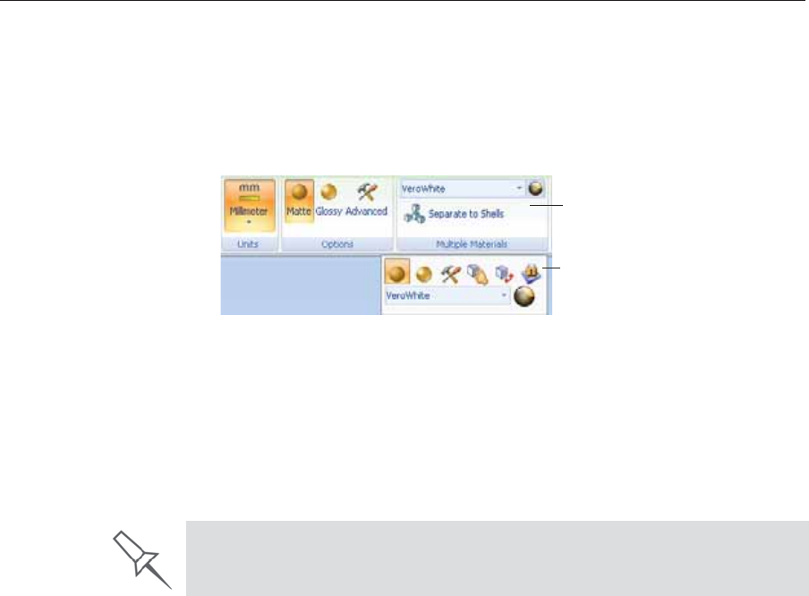
Using Objet Studio
5–22 DOC08010 Rev. A (DRAFT 1)
Assigning a
Model Material
to Objects
Youȱcanȱassignȱanyȱofȱtheȱavailableȱȱtoȱobjectsȱonȱtheȱbuildȱtray.ȱ
To assign a model material to objects:
1. Selectȱanȱobjectȱonȱtheȱbuildȱtrayȱ(seeȱ“SelectingȱObjects”ȱonȱpage 18).
Whenȱanȱobjectȱisȱselected,ȱitsȱproperties—includingȱmodelȱmaterials—
areȱdisplayedȱonȱtheȱModelȱToolbarȱandȱonȱtheȱribbon.
Figure 5-26: Object properties, on ribbon and Model Toolbar
2. DisplayȱtheȱmaterialȱdropȬdownȱlistȱandȱselectȱtheȱdesiredȱmaterial.
Figure 5-27: Menu for assigning materials to objects
WhenȱyouȱdeȬselectȱtheȱobjectȱonȱtheȱbuildȱtray,ȱitȱisȱdisplayed,ȱbyȱ
default,ȱwithȱtheȱcolorȱofȱtheȱmaterialȱyouȱselected.ȱInȱtheȱsameȱway,ȱ
youȱcanȱassignȱmodelȱmaterialsȱtoȱeachȱofȱtheȱindependentȱobjectsȱonȱ
theȱbuildȱtray.
Ribbon
Model Toolbar
To separate an object into independent, component parts (each an stl file),
see “Splitting Objects into Components” on page 19.
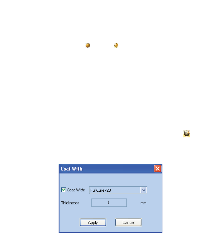
DOC08010 Rev. A (DRAFT 1) 5–23
Stratasys P750K User Guide
Surface Finish Modelsȱcanȱbeȱprintedȱwithȱaȱmatteȱorȱglossyȱsurfaceȱfinish.ȱToȱcreateȱaȱ
matteȱfinish,ȱtheȱprinterȱsurroundsȱmodelsȱwithȱaȱthinȱlayerȱofȱsupportȱ
material.ȱ
To set the model finish:
1. Selectȱtheȱmodel.
2. SelectȱMatteȱȱorȱGlossyȱinȱoneȱofȱtheȱfollowingȱplaces:
•ModelȱSettingsȱribbon,ȱOptionsȱgroup
•ModelȱToolbar
•rightȬclickȱcontextȱmenuȱ(whenȱselectingȱtheȱmodel)
YouȱcanȱconfigureȱObjetȱStudioȱtoȱdistinguishȱbetweenȱobjects’ȱsurfaceȱ
finishȱonȱtheȱbuildȱtrayȱbyȱcolor.ȱToȱconfigureȱhowȱObjetȱStudioȱdisplaysȱ
objects,ȱseeȱ“SettingȱObjectȱColors”ȱonȱpage 41.
Coating
Objects Youȱcanȱprintȱcompositeȱmodelsȱwhereȱtheȱsurfaceȱlayerȱisȱaȱdifferentȱ
materialȱthanȱtheȱinside.ȱThisȱcanȱbeȱusefulȱtoȱachieveȱuniqueȱmechanicalȱ
andȱtexturalȱcharacteristics.ȱThisȱtechniqueȱisȱcalledȱ“coating.”ȱ
To coat an object with a different model material:
1. Selectȱanȱobjectȱonȱtheȱbuildȱtray.
2. OnȱtheȱModelȱToolbarȱorȱtheȱModelȱSettingsȱribbon,ȱclickȱ.
TheȱCoatȱwithȱdialogȱboxȱopens.
3. SelectȱCoat Withȱand,ȱfromȱtheȱdropȬdownȱlist,ȱselectȱtheȱcoatingȱ
material.
Figure 5-28: Coating material selected
4. InȱtheȱThicknessȱfield,ȱenterȱaȱcoatingȱthicknessȱbetweenȱ0.3ȱandȱ3ȱ
millimeters.
Note: The coating thickness does not affect the external dimensions of the
object, which remain unchanged. The coating layer replaces part of
the main model material.
5. ClickȱApply.
Note: When you de-select objects, they are displayed, by default, with
colors representing the model-material. Even after adding a coating
to an object, its color remains that of the main material, not the color
of the coating material.
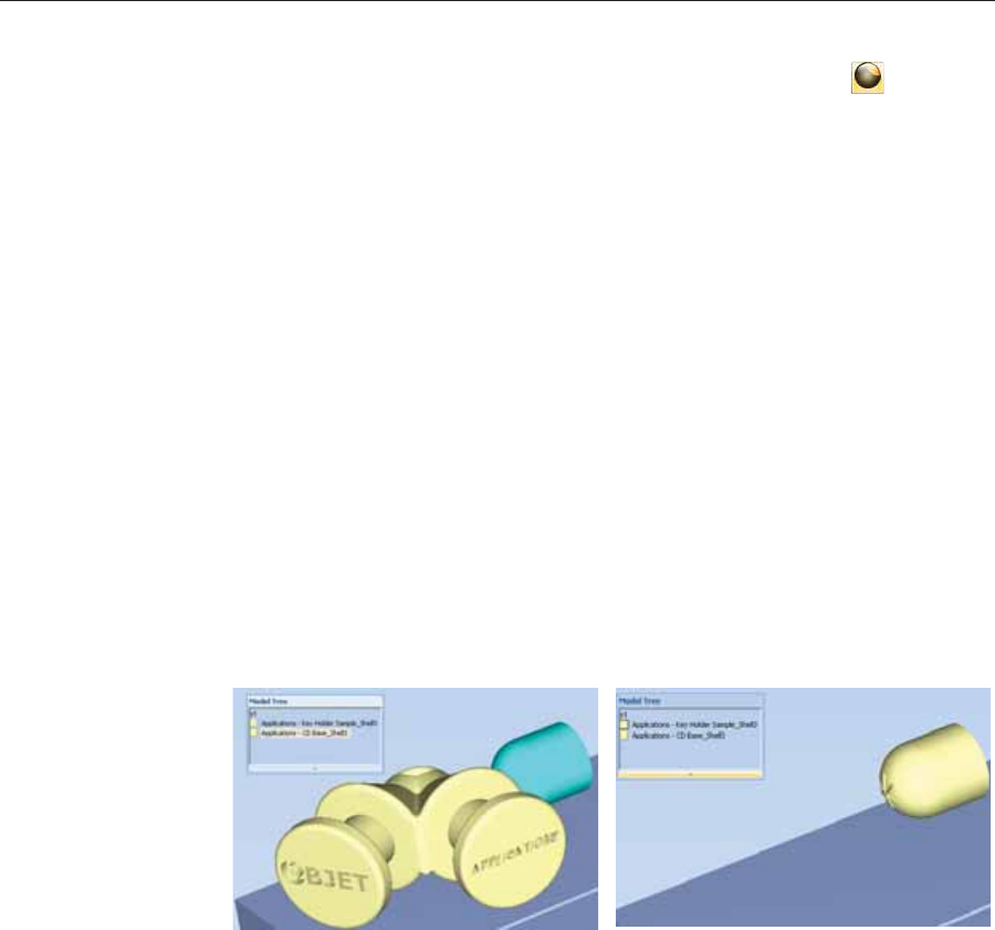
Using Objet Studio
5–24 DOC08010 Rev. A (DRAFT 1)
To inspect, modify or remove the coating applied to an object:
1. OnȱtheȱModelȱToolbarȱorȱtheȱModelȱSettingsȱribbon,ȱclickȱ.
TheȱCoatȱwithȱdialogȱboxȱopens.
2. Performȱoneȱofȱtheȱfollowingȱactions—
•Changeȱtheȱcoatingȱsettings,ȱandȱclickȱApply.
•Toȱremoveȱtheȱcoating,ȱclearȱtheȱCoatȱWithȱcheckȱboxȱandȱclickȱApply.
•Toȱkeepȱtheȱcurrentȱcoatingȱsettings,ȱclickȱApplyȱorȱCancel.
Assigning
Properties to
Hidden
Objects
Toȱenableȱyouȱtoȱassignȱmaterialsȱandȱotherȱpropertiesȱtoȱpartsȱofȱobjectsȱ
thatȱareȱhiddenȱfromȱviewȱonȱtheȱbuildȱtrayȱdisplay,ȱyouȱcanȱtemporarilyȱ
turnȱoffȱtheȱdisplayȱofȱsomeȱobjects.ȱ
To prevent the display of objects:
1. RightȬclickȱanȱobject,ȱeitherȱonȱtheȱbuildȱtrayȱorȱinȱtheȱmodelȱtree.
2. Fromȱtheȱmenuȱthatȱopens,ȱselectȱoneȱofȱtheȱfollowingȱoptions—
•Hide,ȱtoȱcauseȱtheȱselectedȱobjectȱtoȱdisappear.
•Hide Others,ȱtoȱcauseȱallȱotherȱobjectsȱonȱtheȱbuildȱtrayȱtoȱdisappear,ȱ
soȱthatȱonlyȱtheȱselectedȱobjectȱisȱdisplayed.
Alternately,ȱyouȱcanȱclearȱtheȱcheckȱboxȱnextȱtoȱtheȱnameȱofȱtheȱ
objectȱinȱtheȱmodelȱtreeȱtoȱcauseȱthatȱobjectȱtoȱdisappear.
Figure 5-29: All objects displayed Figure 5-30: Outer object hidden
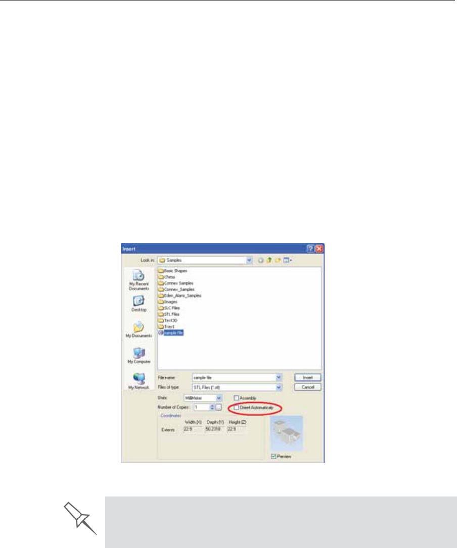
DOC08010 Rev. A (DRAFT 1) 5–25
Stratasys P750K User Guide
Positioning Objects on the Build Tray
Toȱproduceȱmodelsȱefficientlyȱandȱwithȱtheȱrequiredȱfinish,ȱitȱisȱimportantȱ
toȱcarefullyȱpositionȱobjectsȱonȱtheȱbuildȱtray.ȱObjetȱStudioȱsupportsȱtheȱ
automaticȱpositioningȱofȱobjects.ȱHowever,ȱyouȱshouldȱcheckȱtoȱmakeȱsureȱ
thatȱtheȱobjectsȱareȱorientatedȱoptimallyȱforȱyourȱneeds,ȱaccordingȱtoȱtheȱ
considerationsȱexplainedȱinȱ“ModelȱOrientation”ȱonȱpage 26.
Twoȱthingsȱthatȱaffectȱtheȱpositioningȱofȱobjectsȱonȱtheȱbuildȱtrayȱareȱ
orientationȱandȱplacement.ȱYouȱcanȱletȱObjetȱStudioȱdetermineȱtheȱoptimumȱ
orientationȱandȱposition,ȱorȱyouȱcanȱcontrolȱthem.
Automatic
Orientation Byȱdefault,ȱObjetȱStudioȱautomaticallyȱorientsȱobjects,ȱwhenȱplacedȱonȱtheȱ
buildȱtray,ȱforȱtheȱshortestȱprintingȱtime.ȱ(Youȱcanȱlaterȱchangeȱtheȱ
orientationȱmanually.)ȱHowever,ȱyouȱcanȱcancelȱautomaticȱorientationȱ
whenȱplacingȱanȱobjectȱonȱtheȱbuildȱtray.
To place an object on the build tray without automatic orientation:
¾InȱtheȱInsertȱdialogȱbox,ȱmakeȱsureȱOrientȱAutomaticallyȱisȱnotȱselected.
Figure 5-31: Orient Automatically option disabled
You can change the default setting, so that automatic orientation is not
applied unless you select the Orient Automatically check box each time you
place an object on the build tray. To do this, see “Default Settings” on
page 63.

Using Objet Studio
5–26 DOC08010 Rev. A (DRAFT 1)
Automatic
Placement Afterȱplacingȱseveralȱobjectsȱonȱtheȱbuildȱtray,ȱyouȱcanȱletȱObjetȱStudioȱ
arrangeȱthemȱbeforeȱprinting.ȱThisȱensuresȱthatȱtheȱobjectsȱareȱpositionedȱ
properly,ȱandȱthatȱtheyȱwillȱbeȱprintedȱinȱtheȱshortestȱtimeȱandȱwithȱaȱ
minimumȱofȱmaterial.
To automatically arrange objects on the build tray:
¾OnȱtheȱTrayȱSettingsȱribbon,ȱclickȱ.
or—
FromȱtheȱToolsȱmenu,ȱselect Automatic Placement.
Theȱeffectsȱofȱautomaticȱpositioningȱareȱshownȱinȱtheȱfiguresȱbelow.
Figure 5-32: Tray before objects are properly arranged
Figure 5-33: Tray arrangement after applying Automatic Placement
Manual
Positioning Youȱcanȱchangeȱtheȱpositionȱofȱobjectsȱonȱtheȱbuildȱtray—evenȱifȱtheyȱwereȱ
insertedȱwithȱtheȱOrientȱAutomaticallyȱoption.ȱConsiderationsȱforȱ
positioningȱobjectsȱareȱpresentedȱinȱ“ModelȱOrientation,”ȱbelow.ȱToolsȱforȱ
changingȱtheȱpositionȱofȱobjectsȱareȱpresentedȱinȱ“ManipulatingȱObjectsȱonȱ
theȱBuildȱTray”ȱonȱpage 27.
Model Orientation
Theȱorientationȱofȱmodelsȱonȱtheȱbuildȱtrayȱaffectsȱhowȱquicklyȱandȱ
efficientlyȱtheyȱwillȱbeȱproducedȱbyȱtheȱ3Dȱprinter,ȱwhereȱandȱhowȱmuchȱ
supportȱmaterialȱisȱused,ȱandȱwhetherȱorȱnotȱmodelȱpartsȱwillȱhaveȱaȱglossyȱ
finish.ȱTherefore,ȱyouȱshouldȱconsiderȱaȱvarietyȱofȱfactorsȱwhenȱdecidingȱ
howȱtoȱplaceȱmodelsȱonȱtheȱtray,ȱusingȱtheȱfollowingȱpositioningȱrules.ȱ
X-Y-Z Rule
Thisȱruleȱconsidersȱaȱmodelȇsȱouterȱdimensions.
¾SinceȱtheȱprintȱheadsȱmoveȱbackȱandȱforthȱalongȱtheȱXȬaxis,ȱtheȱprintingȱ
timeȱalongȱthisȱaxisȱisȱrelativelyȱshort,ȱcomparedȱtoȱprintingȱtimeȱalongȱ
theȱYȬaxisȱandȱZȬaxis.ȱFromȱthisȱpointȱofȱview,ȱitȱisȱadvisableȱtoȱplaceȱtheȱ
objectȇsȱlargestȱdimensionȱalongȱtheȱXȬaxis.
¾Anyȱsurfacesȱthatȱcomeȱintoȱcontactȱwithȱsupportȱmaterialsȱbecomeȱ
matte.
¾Sinceȱmodelsȱareȱbuiltȱup,ȱonȱtheȱZȬaxis,ȱinȱ16Ȭȱorȱ30Ȭmicronȱlayersȱ
(accordingȱtoȱtheȱprintingȱmode),ȱitȱisȱveryȱtimeȬconsumingȱtoȱprintȱaȱ
tallȱobject.ȱFromȱthisȱpointȱofȱview,ȱitȱisȱadvisableȱtoȱplaceȱtheȱobjectȇsȱ
smallestȱdimensionȱalongȱtheȱZȬaxis.
¾Sinceȱtheȱprintȱheadsȱmeasureȱaboutȱ2ȱinchesȱ(5ȱcentimeters)ȱonȱtheȱ
YȬaxis,ȱmodelsȱmeasuringȱlessȱthanȱthisȱ(onȱtheȱYȬaxis)ȱareȱprintedȱinȱ
oneȱpass.ȱFromȱthisȱpointȱofȱview,ȱitȱisȱadvisableȱtoȱplaceȱtheȱobjectȇsȱ
intermediateȱdimensionȱalongȱtheȱYȬaxis.
¾For best results, arrange the tray with Automatic Placement, on the Tray
Settings ribbon, even if you inserted the objects with the Orient
Automatically option.
¾The physical characteristics of each type of Model material you use can
affect the positioning of objects on the tray. Therefore, select materials
before running Automatic Placement.

DOC08010 Rev. A (DRAFT 1) 5–27
Stratasys P750K User Guide
Tall-Left Rule
Thisȱruleȱconsidersȱmodelsȱwhere,ȱafterȱbeingȱorientatedȱonȱtheȱbuildȱtrayȱ
accordingȱtoȱotherȱconsiderations,ȱoneȱsideȱisȱtallerȱthanȱtheȱother.
¾SinceȱtheȱprintȱheadsȱmoveȱalongȱtheȱXȬaxisȱfromȱleftȱtoȱright,ȱtallerȱ
sectionsȱonȱtheȱrightȱrequireȱtheȱprintȱheadsȱtoȱscanȱunnecessarilyȱfromȱ
theȱleftȱuntilȱreachingȱthem.ȱIf,ȱonȱtheȱotherȱhand,ȱtheȱtallerȱsectionsȱareȱ
positionedȱonȱtheȱleftȱofȱtheȱtray,ȱtheȱprintȱheadsȱonlyȱhaveȱtoȱscanȱtheȱ
modelȱuntilȱprintingȱtheseȱsections—onceȱtheȱlowerȱpartsȱhaveȱbeenȱ
completed.ȱTherefore,ȱyouȱshouldȱpositionȱtheȱtallerȱsideȱofȱtheȱmodel,ȱ
whenȱpossible,ȱonȱtheȱleft.
Recess-Up Rule
Thisȱruleȱconsidersȱmodelsȱcontainingȱsurfaceȱrecesses.
¾Recessesȱinȱtheȱsurfaceȱ(likeȱhollows,ȱdrillȱholes,ȱetc.)ȱshould,ȱwhenȱ
possible,ȱbeȱpositionedȱfaceȬup.
Fine-Surface Rule
Thisȱruleȱconsidersȱmodelsȱthatȱhaveȱoneȱsideȱonȱwhichȱthereȱareȱfineȱ
detailsȱ(likeȱtheȱkeypadȱsideȱofȱaȱtelephone).
¾Theȱsideȱofȱtheȱmodelȱcontainingȱfineȱdetailsȱshould,ȱwhenȱpossible,ȱbeȱ
positionedȱfaceȬup.ȱThisȱresultsȱinȱaȱsmoothȱfinish.
Avoid Support-Material Rule
Thisȱruleȱconsidersȱmodelsȱthatȱhaveȱlargeȱholesȱorȱhollows,ȱopenȱonȱatȱ
leastȱoneȱsideȱ(likeȱaȱpipeȱorȱaȱcontainer).
¾Itȱmayȱbeȱadvantageousȱtoȱprintȱaȱmodelȱstandingȱup,ȱsoȱsupportȱ
materialȱdoesȱnotȱfillȱtheȱhollow,ȱevenȱthoughȱprintingȱtheȱmodelȱlyingȱ
downȱwouldȱbeȱmuchȱfaster.
Manipulating Objects on the Build Tray
Positioning
Objects on the
Z-Axis
Whenȱyouȱuseȱtheȱautomaticȱpositioningȱoptionȱtoȱarrangeȱobjectsȱonȱtheȱ
buildȱtrayȱ(seeȱ“AutomaticȱOrientation”ȱonȱpage 25),ȱtheȱobjectsȱareȱ
positionedȱdirectlyȱonȱtheȱtray.ȱIfȱyouȱdoȱnotȱinsertȱobjectsȱwithȱautomaticȱ
positioning,ȱtheyȱoftenȱappearȱeitherȱaboveȱorȱbelowȱtheȱtray.
To position objects directly on the tray:
1. Selectȱtheȱobject.
2. FromȱtheȱObjectȱmenu,ȱselectȱLay On.
The following rules are based on the fact that support material is not
required on the top of the printed model.
In practice, the Stratasys system prints all models on the build tray on a one-
millimeter bed of support material. The importance of positioning objects
directly on the build tray with Objet Studio is to correctly display the objects
on the screen.
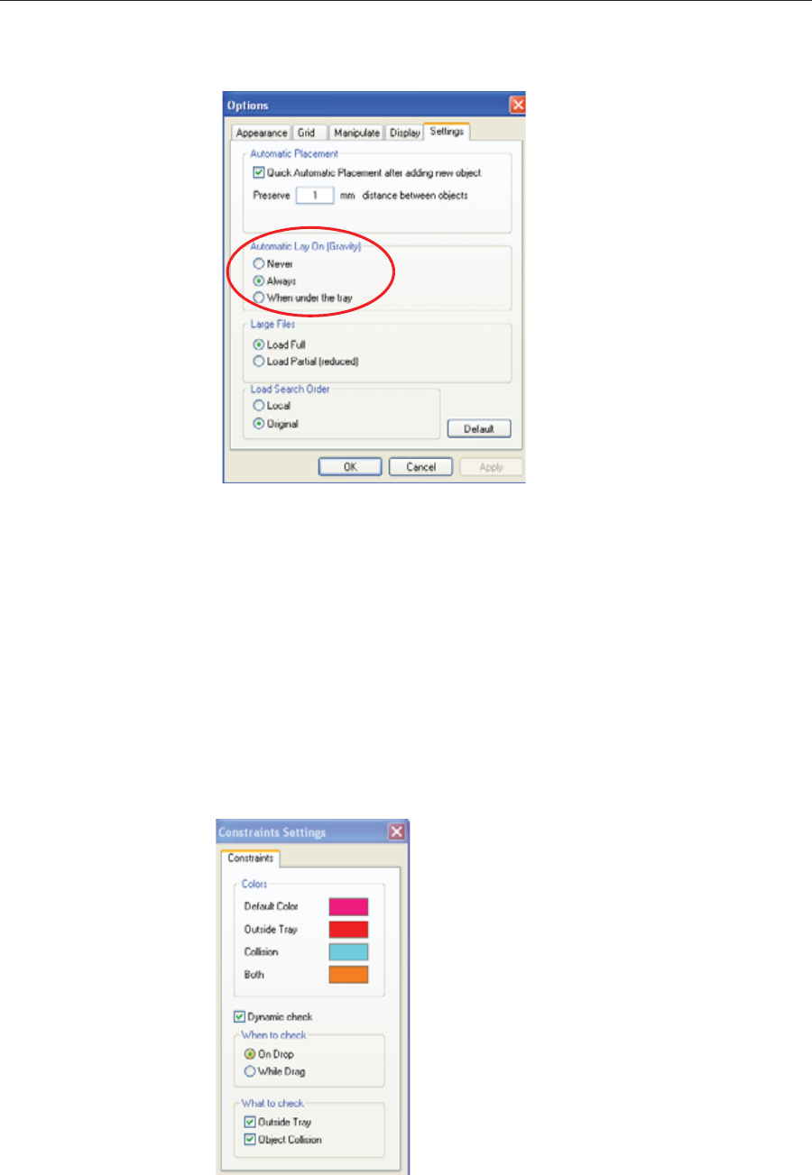
Using Objet Studio
5–28 DOC08010 Rev. A (DRAFT 1)
To ensure that objects are always positioned directly on the tray:
1. FromȱtheȱToolsȱmenu,ȱselectȱOptions,ȱandȱdisplayȱtheȱSettingsȱtab.
Figure 5-34: Options dialog box, Settings tab
2. InȱtheȱAutomaticȱLayȱOnȱ(Gravity)ȱsection,ȱselectȱAlways.ȱ
Other Z-axis options (in the Automatic Lay On section):
•When under the tray—Theȱdisplayȱofȱobjectsȱthatȱareȱbelowȱtheȱbuildȱ
trayȱisȱautomaticallyȱchangedȱsoȱthatȱtheȱobjectȱisȱatȱtrayȱlevel.
•Never—Theȱdisplayȱofȱobjectsȱthatȱareȱaboveȱorȱbelowȱtheȱbuildȱtrayȱisȱ
notȱchanged.
Valid Object
Placement Youȱcanȱensureȱthatȱmodelsȱdoȱnotȱoverlapȱwhenȱyouȱpositionȱthemȱonȱtheȱ
buildȱtray,ȱandȱthatȱtheyȱdoȱnotȱextendȱbeyondȱtheȱtray.ȱ
To ensure valid object placement:
1. FromȱtheȱToolsȱmenu,ȱselectȱConstraints Settings.
Figure 5-35: Constraints Settings dialog box

DOC08010 Rev. A (DRAFT 1) 5–29
Stratasys P750K User Guide
2. SelectȱDynamic checkȱtoȱidentify—
•invalidȱobjectȱplacementȱwhileȱplacingȱobjects—OnȱDropȱselected.
•invalidȱobjectȱplacementȱafterȱmovingȱobjects—WhileȱDragȱselected.
•objectsȱplacedȱbeyondȱtheȱtray’sȱboundaries—OutsideȱTrayȱselected.
•objectsȱthatȱoverlap—ObjectȱCollisionȱselected.
Note: Because of the unique characteristics of each type of model material
and finish, always check valid placement after changing the material/
finish. Remember that Objet Studio calculates the space occupied by
an object including the “bounding box” surrounding it (see
figure 5-50 on page 38).
Even if you do not use Dynamic Check when placing objects on the build
tray, Objet Studio automatically checks if there is a problem with the
positioning of objects on the tray before sending it to the printer. You can
also manually check for problems after positioning objects (see “Tray
Validation” on page 45).
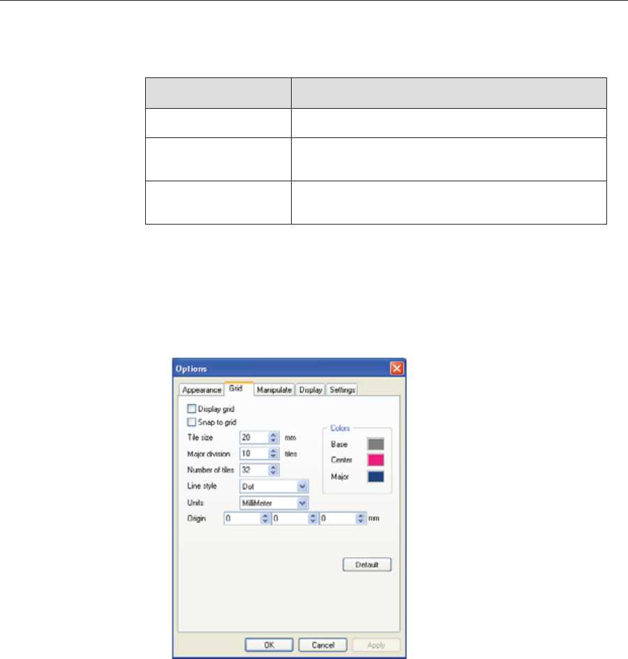
Using Objet Studio
5–30 DOC08010 Rev. A (DRAFT 1)
Using a Grid to
Position
Objects
Displayingȱaȱgridȱonȱtheȱimageȱofȱtheȱbuildȱtrayȱcanȱbeȱusefulȱwhenȱ
positioningȱobjects.ȱToȱuseȱtheȱgridȱfeatures,ȱselectȱtheȱfollowingȱmenuȱ
options.ȱ
Youȱcanȱreviewȱandȱconfigureȱgridȱsettings—andȱapplyȱthem—fromȱtheȱ
Optionsȱdialogȱbox.
To view and change grid settings:
1. FromȱtheȱToolsȱmenu,ȱselectȱOptions,ȱandȱdisplayȱtheȱGridȱtab.
Theȱcurrentȱgridȱsettingsȱareȱdisplayed.
Figure 5-36: Options dialog box, Grid tab
2. Asȱrequired,ȱchangeȱtheȱsettings,ȱandȱselectȱorȱclearȱtheȱcheckȱboxes.
3. ClickȱApplyȱorȱOK.
Menu Option Result
Toolsȱ>ȱGrid Displaysȱaȱgridȱonȱtheȱbuildȱtray.
Toolsȱ>ȱSnapȱtoȱgrid Whenȱmovingȱtheȱobject,ȱitȱalignsȱwithȱtheȱnearestȱ
gridȱline.
Toolsȱ>ȱOptionsȱ>ȱ
Grid Enablesȱyouȱtoȱchangeȱtheȱgridȱoriginȱ
(XȬȱandȱYȬaxisȱmeetingȱpoint)ȱandȱappearance.
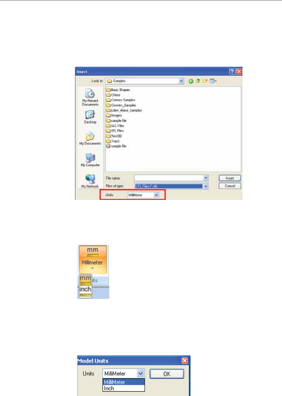
DOC08010 Rev. A (DRAFT 1) 5–31
Stratasys P750K User Guide
Measurement
Units
3Dȱfilesȱcontainȱanȱobjectȇsȱproportions,ȱbutȱnotȱitsȱunitsȱofȱmeasure.ȱ
Therefore,ȱmakeȱsureȱtoȱcorrectlyȱselectȱeitherȱmillimetersȱorȱinchesȱwhenȱ
insertingȱanȱobject.ȱOtherwise,ȱtheȱsizeȱofȱtheȱobjectȱonȱtheȱbuildȱtrayȱwillȱbeȱ
eitherȱmuchȱtooȱlargeȱorȱmuchȱtooȱsmall.ȱ
To set the measurement units when inserting an object:
¾InȱtheȱInsertȱdialogȱbox,ȱUnitsȱfield,ȱselectȱMillimeterȱorȱInch:
Figure 5-37: Units field in the Insert dialog box
To change measurement units for a selected object from the
Model Settings ribbon:
1. OpenȱtheȱUnitsȱflyoutȱtoolbar.
Figure 5-38: Units flyout toolbar
2. Selectȱtheȱmeasurementȱunitsȱdesired.
To change measurement units for a selected object from the standard
toolbar:
1. FromȱtheȱObjectȱmenu,ȱselectȱChange Units.
Figure 5-39: Model Units dialog box
2. InȱtheȱModelȱUnitsȱdialogȱbox,ȱchangeȱtheȱsettingȱandȱclickȱOK.
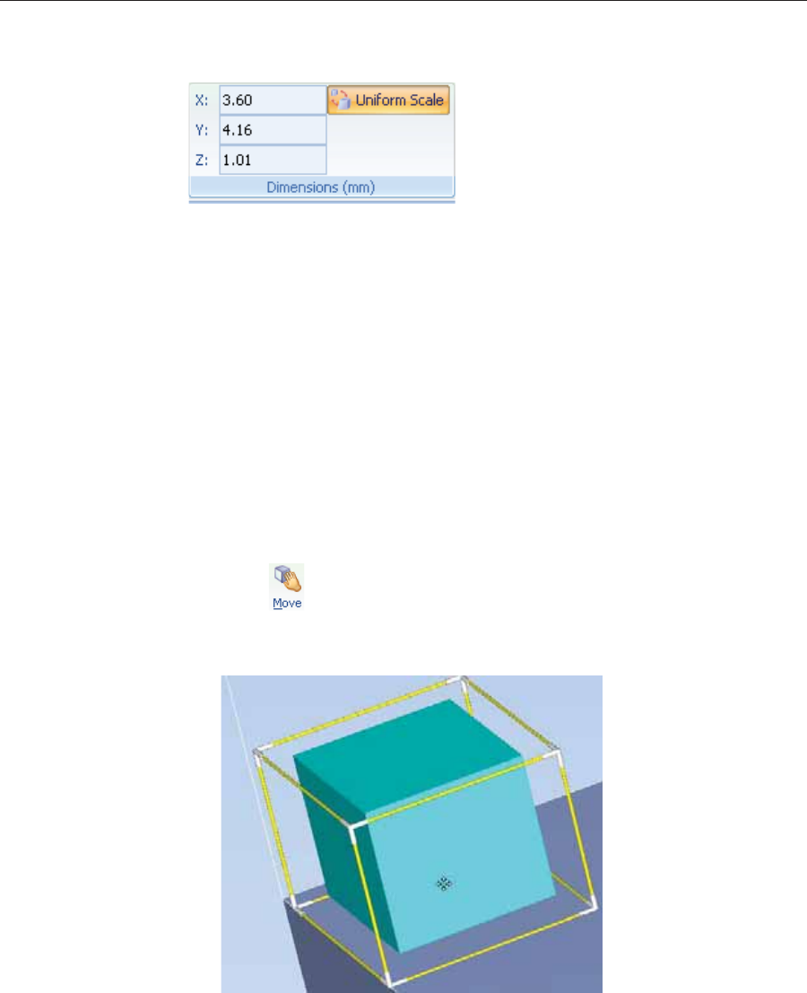
Using Objet Studio
5–32 DOC08010 Rev. A (DRAFT 1)
Setting Model
Dimensions Youȱcanȱchangeȱanȱobject’sȱdimensionsȱbyȱchangingȱitsȱsizeȱonȱtheȱXȬ,ȱYȬ,ȱ
andȱZȬaxes,ȱfromȱtheȱDimensionsȱgroupȱonȱtheȱModelȱSettingsȱribbon.
Figure 5-40: Dimensions on the Model Settings ribbon
•IfȱUniformȱScaleȱisȱenabled,ȱchangingȱtheȱobject’sȱdimensionȱonȱoneȱaxisȱ
affectsȱtheȱotherȱdimensions,ȱproportionately.
•Afterȱchangingȱaȱmeasurement,ȱpressȱEnterȱorȱclickȱinȱanotherȱfieldȱinȱ
theȱDimensionsȱgroup.
Note: You can change the height of the objects on the build tray only if this
is allowed by the Objet Studio settings (see “Positioning Objects on
the Z-Axis” on page 27).
Repositioning
Objects Youȱcanȱmanuallyȱmoveȱandȱrotateȱanȱobjectȱonȱtheȱbuildȱtrayȱwithȱtheȱ
arrowȱkeys,ȱorȱbyȱdraggingȱitȱwithȱtheȱmouse.
To manually manipulate an object:
1. Selectȱanȱobjectȱbyȱclickingȱitȱonȱtheȱbuildȱtray,ȱorȱinȱtheȱmodelȱtreeȱ
pane.ȱ
2. ClickȱȱonȱtheȱModelȱToolbar,ȱorȱonȱtheȱModelȱSettingsȱribbon.
Aȱframeȱappearsȱaroundȱtheȱobject,ȱandȱtheȱcursorȱchangesȱtoȱindicateȱ
thatȱtheȱobjectȱcanȱbeȱmoved.
Figure 5-41: Manually moving an object
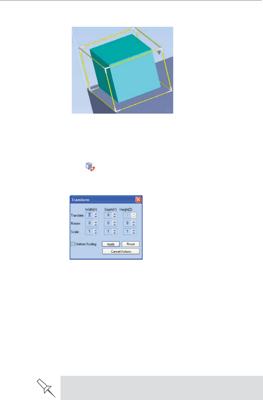
DOC08010 Rev. A (DRAFT 1) 5–33
Stratasys P750K User Guide
3. Ifȱyouȱclickȱonȱaȱcornerȱofȱtheȱframe,ȱtheȱcursorȱchangesȱtoȱindicateȱthatȱ
theȱobjectȱcanȱbeȱrotated.
Figure 5-42: Manually rotating an object
4. Manipulateȱtheȱobjectȱwithȱtheȱarrowȱkeysȱorȱwithȱtheȱmouse.
Using the Transform
Dialog Box Youȱcanȱmakeȱpreciseȱchangesȱtoȱanȱobjectȱbyȱchangingȱtheȱpropertiesȱinȱtheȱ
Transformȱdialogȱbox.
To access the Transform dialog box (when an object is selected):
•ClickȱȱonȱtheȱModelȱToolbarȱorȱonȱtheȱModelȱSettingsȱribbon.
•FromȱtheȱrightȬclickȱcontextȱmenu,ȱselectȱTransform.
•FromȱtheȱObjectȱmenu,ȱselectȱTransform.
Figure 5-43: Transform dialog box
To change an object with the Transform dialog box:
¾Changeȱanyȱofȱtheȱvalues,ȱthenȱclickȱApplyȱtoȱseeȱhowȱtheȱobjectȱchangesȱ
onȱtheȱbuildȱtray.ȱ
Note: The changed values remain in the dialog box after clicking Apply.
Therefore, you can make small changes to values in the dialog box to see
how the object changes on screen each time you click Apply.
To reset all of the values in the dialog box:
¾ClickȱReset.
Note:
The object does not change. Any changes previously applied remain.
To undo all changes made with the Transform dialog box:
¾ClickȱCancel Actions.
After closing the Transform dialog box, clicking Undo (on the Model Settings
ribbon or from the Edit menu) cancels all changes made with the dialog box.
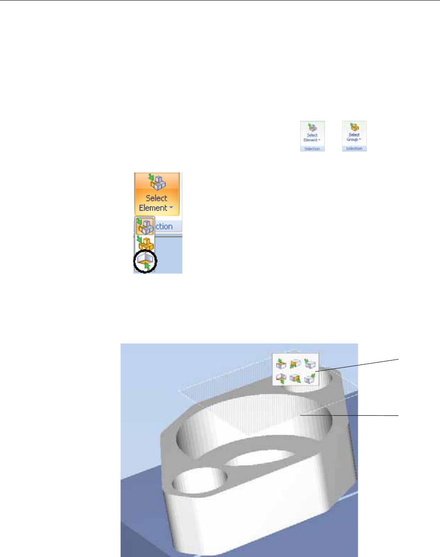
Using Objet Studio
5–34 DOC08010 Rev. A (DRAFT 1)
Changing an
Object’s
Orientation
Thereȱareȱseveralȱmethodsȱforȱchangingȱtheȱorientationȱofȱobjectsȱonȱtheȱ
buildȱtray.
To rotate an object:
¾SelectȱtheȱobjectȱandȱuseȱtheȱObjectȱmenuȱoptionsȱ(seeȱalsoȱ
“RepositioningȱObjects”ȱonȱpage 32).
To re-align an object’s plane:
1. OnȱtheȱTrayȱSettingsȱorȱModelȱSettingsȱribbon—
a. ClickȱtheȱiconȱinȱtheȱSelectionȱgroup:ȱȱorȱ.
b. Onȱtheȱflyoutȱtoolbar,ȱclickȱtheȱSelectȱPlaneȱicon:
or—
FromȱtheȱToolsȱmenu,ȱselectȱPlane Alignment > Select Plane.
2. Clickȱonȱpartȱofȱanȱobjectȱonȱtheȱbuildȱtray.
Theȱselectedȱplaneȱisȱdisplayed.
Figure 5-44: Aligning by plane
Alignment
toolbar
Selected
plane
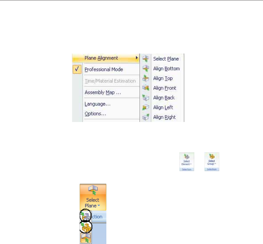
DOC08010 Rev. A (DRAFT 1) 5–35
Stratasys P750K User Guide
3. OnȱtheȱAlignmentȱtoolbar,ȱclickȱanȱappropriateȱiconȱtoȱchangeȱtheȱ
alignment.ȱ
or—
FromȱtheȱToolsȱmenu,ȱselectȱPlane Alignment,ȱandȱselectȱanȱalignmentȱ
option.
Figure 5-45: Tools menu, Plane Alignment options
To cancel plane selection after re-aligning objects on the build tray:
¾OnȱtheȱTrayȱSettingsȱorȱModelȱSettingsȱribbon—
a. ClickȱtheȱiconȱinȱtheȱSelectionȱgroup:ȱȱorȱ.
b. Onȱtheȱflyoutȱtoolbar,ȱclickȱtheȱSelectȱElementȱorȱSelectȱGroupȱicon:
or—
¾FromȱtheȱToolsȱmenu,ȱselectȱPlane Alignment > Select Plane.
To flip an object 180 degrees on any axis:
1. Selectȱtheȱobject.
2. FromȱtheȱObjectȱmenu,ȱselectȱFlip > Flip X / Flip Y / Flip Z.
To make precise changes to the object’s orientation on any axis:
1. Selectȱtheȱobject.ȱ
2. DisplayȱtheȱTransformȱdialogȱboxȱ(seeȱfigure 5Ȭ43ȱonȱpage 33).
3. ChangeȱtheȱRotateȱparametersȱforȱeachȱaxis.
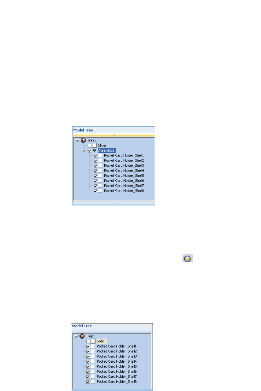
Using Objet Studio
5–36 DOC08010 Rev. A (DRAFT 1)
Grouping and
Ungrouping
Objects
Youȱcanȱmanipulateȱtwoȱorȱmoreȱobjectsȱonȱtheȱbuildȱtray,ȱatȱtheȱsameȱtime.
•Selectingȱmultipleȱobjects
Manipulatingȱdoneȱtoȱoneȱobjectȱaffectsȱallȱselectedȱobjects.ȱForȱ
example,ȱturningȱoneȱobjectȱonȱitsȱaxisȱcausesȱallȱselectedȱobjectsȱtoȱturnȱ
onȱtheirȱrespectiveȱaxes.
•Convertingȱtheȱobjectsȱtoȱanȱassembly
Separateȱobjectsȱbecomeȱpartsȱofȱoneȱunit.ȱForȱexample,ȱturningȱtheȱ
assemblyȱonȱitsȱaxisȱcausesȱallȱitsȱcomponentȱpartsȱtoȱturnȱasȱoneȱunit.
To convert objects to an assembly:
1. Selectȱtheȱobjectsȱ(seeȱ“SelectingȱObjects”ȱonȱpage 18)
2. FromȱtheȱObjectȱmenu,ȱselectȱGroup to Assembly.
Inȱtheȱmodelȱtree,ȱtheȱobjectsȱnowȱappearȱasȱchildrenȱofȱaȱparentȱ
(assembly).ȱ
Figure 5-46: Assembly in the model tree
Afterȱcreatingȱanȱassembly,ȱyouȱcanȱsaveȱitȱasȱanȱobjdfȱfile,ȱforȱreȬuse.ȱ
(Savingȱtheȱassemblyȱisȱnotȱnecessaryȱforȱmanipulatingȱandȱprintingȱit.)
To save an assembly:
1. Selectȱtheȱassemblyȱ(eitherȱonȱtheȱbuildȱtrayȱorȱinȱtheȱmodelȱtree).
2. FromȱtheȱObjetȱStudioȱCommandsȱmenuȱ,selectȱSave As.
3. Inȱthe SaveȱAsȱdialogȱbox,ȱselectȱtheȱobjdfȱformat,ȱchooseȱaȱlocation,ȱ
nameȱtheȱfile,ȱandȱclickȱSave.
To separate assemblies into individual objects (stl files):
1. Selectȱtheȱassemblyȱ(eitherȱonȱtheȱbuildȱtrayȱorȱinȱtheȱmodelȱtree).
2. FromȱtheȱObjectȱmenu,ȱselectȱUngroup.
Inȱtheȱmodelȱtree,ȱtheȱelementsȱareȱnotȱpartsȱofȱanȱassembly.
Figure 5-47: Separate objects in the model tree

DOC08010 Rev. A (DRAFT 1) 5–37
Stratasys P750K User Guide
Freezing Model
Orientation Ifȱyouȱmanipulateȱanȱobjectȱonȱtheȱbuildȱtray,ȱyouȱcanȱfreezeȱitsȱorientationȱ
soȱthatȱitȱdoesȱnotȱchangeȱwhenȱyouȱpositionȱitȱautomaticallyȱ(seeȱ
“AutomaticȱPlacement”ȱonȱpage 26).
To freeze an object:
1. Selectȱanȱobjectȱonȱtheȱbuildȱtray.
2. OnȱtheȱModelȱSettingsȱribbon,ȱinȱtheȱManipulateȱgroup,ȱorȱonȱtheȱModelȱ
Toolbar,ȱclickȱ.
To unfreeze an object:
¾Selectȱtheȱobjectȱandȱclickȱȱ(toȱdeȬselectȱit).
Display Options
Viewing
Objects FromȱtheȱViewȱmenu,ȱyouȱcanȱchangeȱtheȱwayȱobjectsȱareȱdisplayed.ȱTheȱ
defaultȱmethodȱforȱdisplayingȱmodelsȱonȱtheȱbuildȱtrayȱisȱasȱsolidȱ
(“shaded”)ȱobjects.ȱ
Figure 5-48: Tray and model displayed in Shaded view
TheȱotherȱdisplayȱoptionsȱareȱWireFrameȱandȱPoints.
To display the build tray in WireFrame view:
¾FromȱtheȱViewȱmenu,ȱselectȱWireFrame.
Figure 5-49: Tray and model displayed in WireFrame view
To revert to the shaded view:
¾FromȱtheȱViewȱmenu,ȱselect Shaded.
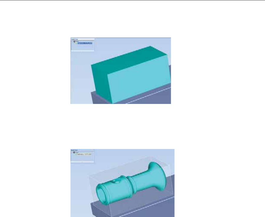
Using Objet Studio
5–38 DOC08010 Rev. A (DRAFT 1)
To display objects as boxes, showing their maximum dimensions
instead of their shape:
¾FromȱtheȱViewȱmenu,ȱselect Display Bounding Box.
Figure 5-50: Model displayed with bounding box
To display the area around objects needed for support material (to
produce a matte finish):
¾FromȱtheȱViewȱmenu,ȱselect Display Thickening Box.
Figure 5-51: Model displayed with thickening box
To display the maximum build height:
¾FromȱtheȱViewȱmenu,ȱselectȱDisplay Tray 3D Box.
Figure 5-52: Tray 3D Box
To display objects without the build tray:
¾FromȱtheȱViewȱmenu,ȱclearȱ(deȬselect)ȱtheȱDisplayȱTrayȱoption.
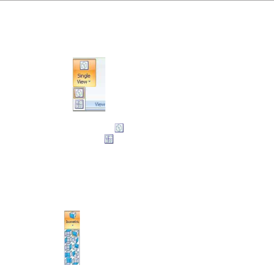
DOC08010 Rev. A (DRAFT 1) 5–39
Stratasys P750K User Guide
Screen Layout ObjetȱStudioȱautomaticallyȱadjustsȱtheȱdefaultȱscreenȱlayoutȱtoȱdisplayȱtheȱ
optimumȱviewsȱofȱtheȱbuildȱtrayȱandȱtheȱmodelȱtree.ȱYouȱcanȱviewȱmodelsȱ
fromȱdifferentȱperspectivesȱbyȱchangingȱtheȱscreenȱlayout.
To change the screen layout:
¾OnȱtheȱViewȱflyoutȱtoolbar,ȱselectȱSingle View,ȱorȱ4 Views.
Figure 5-53: Screen layout icons
Single View ȱisȱtheȱdefaultȱscreenȱlayout.
4 Viewsȱȱdisplaysȱperspective,ȱtop,ȱfrontȱandȱrightȱviews.
Figure 5-54: Single-view screen layout
Figure 5-55: 4-view screen layout
Tray
Perspective Theȱdefaultȱperspectiveȱofȱtheȱbuildȱtrayȱisȱ“isometric.”ȱYouȱcanȱchangeȱtheȱ
perspectiveȱofȱtheȱactiveȱwindowȱwithȱoneȱofȱtenȱoptions.
To change the perspective of the build tray in the active window:
1. OnȱtheȱTrayȱSettingsȱribbon,ȱopenȱtheȱPerspectiveȱflyoutȱtoolbar.
Figure 5-56: Perspective flyout toolbar
2. Clickȱtheȱiconȱthatȱrepresentsȱtheȱdesiredȱperspective.
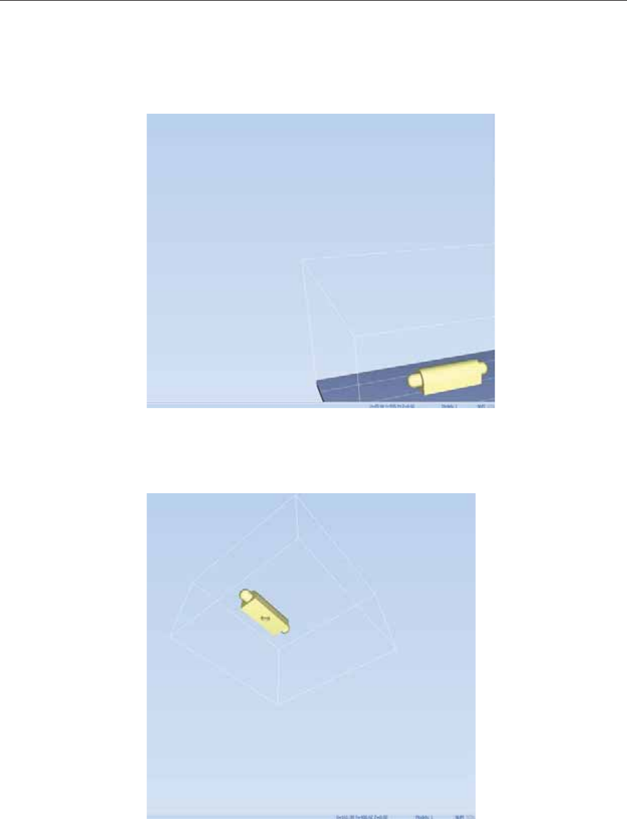
Using Objet Studio
5–40 DOC08010 Rev. A (DRAFT 1)
Tray Positioning Toȱviewȱtheȱtrayȱandȱmodelsȱfromȱdifferentȱdirections,ȱyouȱcanȱmoveȱtheȱ
trayȱaroundȱtheȱscreenȱandȱchangeȱitsȱdisplayȱangle.
To move the tray in the Objet Studio screen:
¾Pressȱtheȱmouseȱwheelȱwhileȱmovingȱtheȱmouse.
Figure 5-57: Tray after moving it in the Objet Studio display
To manually rotate the tray:
¾PressȱAltȱandȱpressȱtheȱmouseȱwheelȱwhileȱmovingȱtheȱmouse.
Figure 5-58: Tray after rotating it upside-down
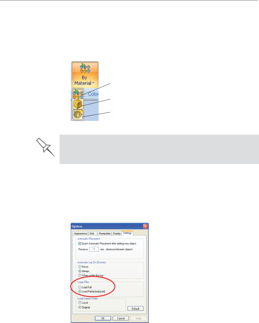
DOC08010 Rev. A (DRAFT 1) 5–41
Stratasys P750K User Guide
Setting Object
Colors Theȱcolorȱofȱobjectsȱonȱtheȱbuildȱtrayȱcanȱindicateȱhowȱtheyȱareȱprinted.ȱ
ObjetȱStudioȱenablesȱyouȱtoȱchooseȱtheȱcolorȱdisplayȱsoȱthatȱyouȱcanȱeasilyȱ
seeȱtheȱmaterial,ȱsurfaceȱandȱcoatingȱofȱobjects.
To choose how colors are applied on the display:
¾OnȱtheȱModelȱSettingsȱribbon,ȱinȱtheȱColorsȱgroup,ȱselectȱoneȱofȱtheȱ
optionsȱfromȱtheȱflyoutȱtoolbar.
Figure 5-59: Colors display options
Loading Large
Files Veryȱlargeȱstlȱfilesȱcanȱbeȱslowȱtoȱloadȱandȱmayȱbeȱdifficultȱtoȱmanipulateȱ
easilyȱonȱtheȱbuildȱtray.ȱIfȱthisȱisȱtheȱcase,ȱyouȱcanȱdisplayȱjustȱanȱimageȱofȱ
theȱobjectȱonȱtheȱbuildȱtrayȱwithoutȱloadingȱtheȱentireȱfile.ȱTheȱstlȱfileȱitselfȱ
isȱnotȱchanged,ȱandȱtheȱcompleteȱfileȱisȱsentȱtoȱtheȱprinter.
To display an image of stl files when you place objects on the build tray:
1. FromȱtheȱToolsȱmenu,ȱselectȱOptions,ȱandȱdisplayȱtheȱSettingsȱtab.
Figure 5-60: Options dialog box, Settings tab
2. InȱtheȱLargeȱFilesȱsection,ȱselectȱLoad Partial (reduced).ȱ
Color Indicates Model material
Color indicates Model surface
Color indicates if coating is used
Before sending a build tray to the printer, or when you perform tray
validation, Objet Studio checks if there is a problem with the stl files or the
positioning of objects on the tray. If so, the affected objects are displayed
with special colors (see “Tray Validation” on page 45).
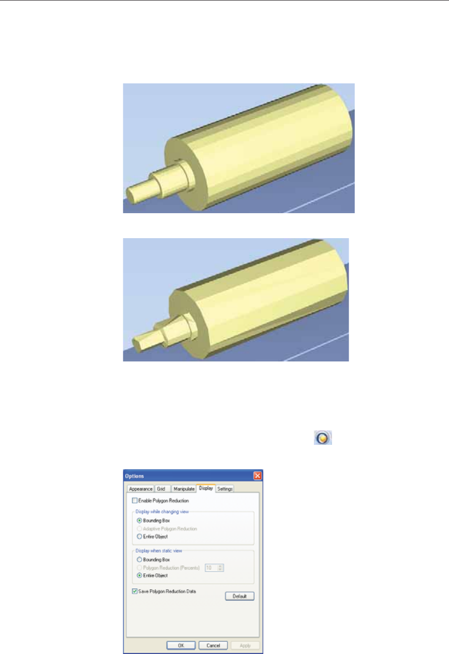
Using Objet Studio
5–42 DOC08010 Rev. A (DRAFT 1)
Large File
Manipulation Ifȱyouȱneedȱtoȱworkȱwithȱaȱdetailedȱmodelȱthatȱisȱcomposedȱofȱaȱlargeȱ
numberȱofȱpolygons,ȱyouȱcanȱspeedȱupȱitsȱdisplayȱandȱmanipulationȱinȱ
ObjetȱStudioȱbyȱreducingȱtheȱnumberȱofȱpolygonsȱonȱtheȱscreen.ȱAlthoughȱ
thisȱmayȱreduceȱtheȱresolutionȱonȱtheȱscreen,ȱitȱhasȱnoȱaffectȱonȱtheȱprintedȱ
models.
Figure 5-61: Object displayed without polygon reduction
Figure 5-62: Object displayed with only five percent of its polygons showing
To use polygon reduction:
1. FromȱtheȱToolsȱmenu,ȱselectȱOptions.
or—
FromȱtheȱObjetȱStudioȱCommandsȱmenuȱ,ȱclickȱOptions.
2. InȱtheȱOptionsȱdialogȱbox,ȱdisplayȱtheȱDisplayȱtab.
Figure 5-63: Options dialog box, Display tab
3. SelectȱEnable Polygon Reduction.

DOC08010 Rev. A (DRAFT 1) 5–43
Stratasys P750K User Guide
4. SelectȱPolygon Reduction (Percent).
5. Enterȱtheȱpercentageȱofȱtotalȱpolygonsȱtoȱdisplay.
WhenȱyouȱclickȱApply,ȱtheȱdisplayȱchanges.
Note: The setting affects the static display (when the object is not being
moved).
6. Setȱdisplayȱoptionsȱwhenȱtheȱobjectȱisȱbeingȱmovedȱ(Displayȱwhileȱ
changingȱview):
•BoundingȱBox—Aȱboxȱrepresentingȱtheȱobject’sȱmaximumȱ
dimensionsȱisȱdisplayed.
•AdaptiveȱPolygonȱReduction—Varyingȱdegreesȱofȱpolygonȱreductionȱ
areȱapplied,ȱasȱnecessary.
•EntireȱObject—Noȱpolygonȱreductionȱisȱapplied.
7. Toȱsaveȱtheseȱsettings,ȱsoȱthatȱtheyȱwillȱbeȱappliedȱeveryȱtimeȱyouȱplaceȱ
thisȱobjectȱonȱtheȱbuildȱtray,ȱclickȱSave Polygon Reduction Data.
8. ClickȱApplyȱtoȱseeȱtheȱresultsȱofȱtheȱsettingsȱwithoutȱclosingȱtheȱdialogȱ
box.
Object display
options Theȱdisplayȱformatȱaffectsȱhowȱquicklyȱobjectsȱdisplay.ȱForȱexample,ȱifȱyouȱ
selectȱBounding Box,ȱobjectsȱdisplayȱfasterȱthanȱtheyȱdoȱwhenȱyouȱselectȱ
Entire Object.ȱYouȱcanȱchooseȱdisplayȱformatsȱforȱobjectsȱwhenȱtheyȱareȱ
stationaryȱ(staticȱview)ȱandȱforȱwhenȱyouȱareȱdraggingȱthemȱ(changingȱview).
To select the object display preference while changing view, and in static
view:
1. Selectȱtoȱdisplayȱobjects:
•WithȱaȱBoundingȱBoxȱ(seeȱfigure 5Ȭ50ȱonȱpage 38)
•WithȱAdaptiveȱPolygonȱReductionȱ(changingȱviewȱonly)
•WithȱPolygonȱReductionȱ(staticȱviewȱonly)
•EntireȱObject
2. ClickȱOKȱwhenȱdone.
Selecting the Entire Object option cancels polygon reduction.
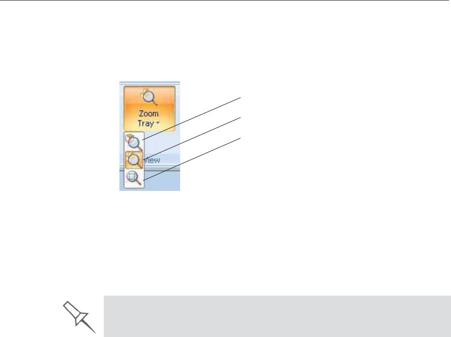
Using Objet Studio
5–44 DOC08010 Rev. A (DRAFT 1)
Zoom Options Whileȱmanipulatingȱobjects,ȱyouȱoftenȱneedȱtoȱviewȱthemȱatȱdifferentȱzoomȱ
levels.ȱ
To change the zoom level:
¾Onȱtheȱribbon,ȱopenȱtheȱZoomȱflyoutȱtoolbarȱandȱselectȱanȱoption:
Figure 5-64: Zoom flyout toolbar
ZoomȱObjectȱfocusesȱonȱtheȱselectedȱobject.
ZoomȱTrayȱdisplaysȱtheȱwholeȱtray.
ZoomȱbyȱRectangleȱallowsȱyouȱtoȱdisplayȱaȱsectionȱofȱtheȱtrayȱbyȱ
selectingȱitȱwithȱtheȱmouse.ȱ
Youȱcanȱalsoȱzoomȱinȱandȱzoomȱoutȱwithȱtheȱmouseȱwheel.
Zoom Object
Zoom Tray
Zoom by Rectangle
You can configure Objet Studio to automatically zoom in on the objects
placed on the build tray. See “Automatic Zoom” on page 63.
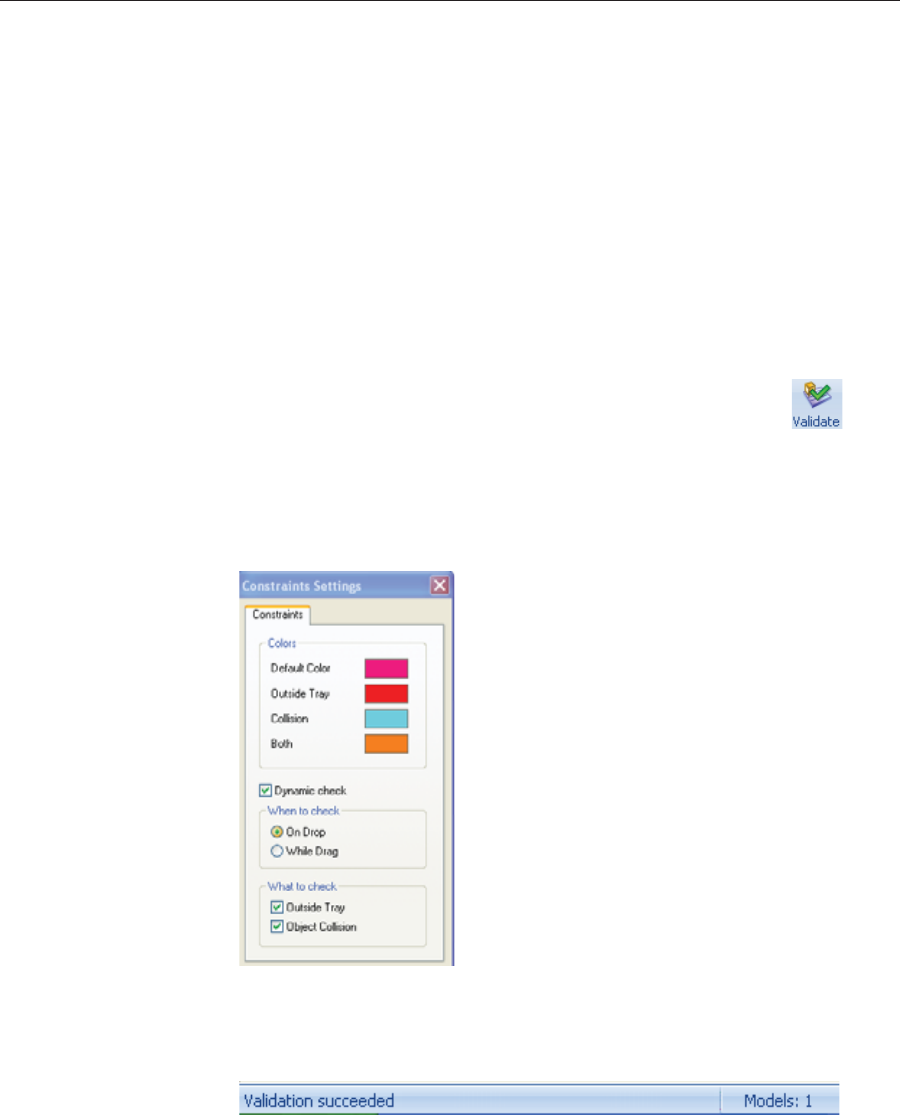
DOC08010 Rev. A (DRAFT 1) 5–45
Stratasys P750K User Guide
Handling Completed Trays
Afterȱyouȱhaveȱproperlyȱplacedȱallȱobjectsȱonȱtheȱbuildȱtray,ȱyouȱsaveȱtheȱ
trayȱasȱanȱobjtfȱfile,ȱwhichȱisȱsentȱtoȱtheȱ3Dȱprinterȱforȱproduction.ȱButȱbeforeȱ
savingȱtheȱtray,ȱyouȱcanȱcheckȱthatȱthereȱwouldȱbeȱnoȱproblemȱproducingȱit.ȱ
Youȱcanȱalsoȱcalculateȱhowȱmuchȱmaterialȱwouldȱbeȱconsumedȱduringȱ
productionȱandȱhowȱmuchȱtimeȱthisȱwouldȱtake.
Tray Validation Beforeȱsendingȱaȱjobȱtoȱtheȱprinterȱforȱproduction,ȱyouȱshouldȱcheckȱthatȱ
theȱtrayȱisȱ“valid”ȱandȱcanȱbeȱprinted.
Note: Because of the unique characteristics of each type of modeling
material, make sure that the correct material is selected before
performing Tray Validation.
To validate that the tray can be printed:
¾OnȱtheȱTrayȱSettingsȱribbon,ȱinȱtheȱBuildȱProcessȱgroup,ȱclickȱ.
or—
FromȱtheȱToolsȱmenu,ȱselectȱPlacement Validation.
Ifȱtheȱtrayȱisȱnotȱvalid,ȱtheȱcolorȱofȱtheȱproblematicȱmodelsȱonȱtheȱtrayȱ
changesȱaccordingȱtoȱaȱpreȬsetȱcode.
Figure 5-65: Color code
Note: The “Both” color also indicates a problematic stl file.
Theȱvalidationȱstatusȱappearsȱonȱtheȱbarȱatȱtheȱbottomȱofȱtheȱscreen.
Figure 5-66: Validation details in status bar
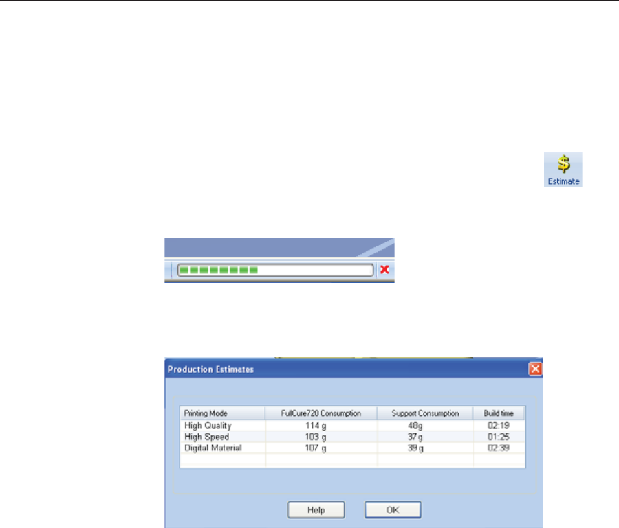
Using Objet Studio
5–46 DOC08010 Rev. A (DRAFT 1)
Production
Estimates ObjetȱStudioȱenablesȱyouȱtoȱcalculateȱtheȱtimeȱandȱmaterialȱresourcesȱ
neededȱforȱproducingȱtraysȱbeforeȱsendingȱthemȱtoȱtheȱprinter.ȱTheȱtimeȱitȱ
takesȱObjetȱStudioȱtoȱperformȱthisȱcalculationȱdependsȱonȱtheȱnumberȱofȱ
objectsȱonȱtheȱtrayȱandȱtheirȱcomplexity.ȱCalculatingȱtheȱproductionȱ
estimateȱforȱaȱfullȱtrayȱcouldȱtakeȱupȱtoȱ15ȱminutes,ȱdependingȱonȱyourȱ
computer’sȱspecifications.ȱ
To calculate the time and materials needed for producing the current
tray:
¾OnȱtheȱTrayȱSettingsȱribbon,ȱinȱtheȱBuildȱProcessȱgroup,ȱclickȱ.
Whileȱtheȱestimateȱisȱbeingȱcalculated,ȱaȱprogressȱbarȱisȱdisplayed—onȱ
theȱrightȱsideȱofȱtheȱstatusȱbarȱ(atȱtheȱbottomȱofȱtheȱscreen).ȱ
Figure 5-67: Estimate progress bar
WhenȱObjetȱStudioȱfinishesȱcalculatingȱtheȱproductionȱresources,ȱtheȱ
resultsȱareȱdisplayedȱinȱaȱdialogȱbox.
Figure 5-68: Production resource calculations for different printing modes
AsȱshownȱinȱtheȱProductionȱEstimatesȱdialogȱbox,ȱtheȱresourcesȱneededȱforȱ
producingȱtheȱmodelsȱonȱtheȱtrayȱdependȱonȱtheȱprintingȱmodeȱusedȱbyȱtheȱ
printerȱwhenȱproducingȱtheȱjob.ȱYouȱmightȱwantȱtoȱconsiderȱtheseȱ
estimatesȱwhenȱdecidingȱonȱtheȱprintingȱmodeȱ(seeȱbelow),ȱandȱwhetherȱorȱ
notȱtoȱallowȱusingȱsubstituteȱmodelȱmaterialsȱwhenȱprintingȱtheȱjob.ȱ
Note: You select the printing mode and material substitute options after
you send the build tray to the printer (see “Printing the Tray File” on
page 48).
Cancel

DOC08010 Rev. A (DRAFT 1) 5–47
Stratasys P750K User Guide
Printing Modes Stratasysȱprintersȱcanȱbuildȱmodelsȱusingȱthreeȱpossibleȱprintingȱmodes.
HQ (High Quality) Mode—
•Modelsȱareȱprintedȱinȱ16Ȭmicronȱlayers,ȱresultingȱinȱsmoothȱsurfaces,ȱ
suitableȱforȱproducingȱfineȬdetailedȱandȱdelicateȱitems.
•Almostȱtwiceȱasȱmuchȱtimeȱisȱrequiredȱtoȱprintȱmostȱtrays,ȱcomparedȱtoȱ
theȱHigh Speedȱsetting.
•Thisȱsettingȱisȱonlyȱavailableȱwhenȱmodelȱmaterialȱcanȱbeȱusedȱinȱfourȱ
printȱheads,ȱinȱsingleȬmaterialȱprinting.
HS (High Speed) Mode—
•Modelsȱareȱproducedȱinȱ30Ȭmicronȱlayers,ȱsuitableȱforȱproducingȱlargerȱ
models.
•Muchȱlessȱtimeȱisȱrequiredȱtoȱprintȱmostȱtrays,ȱcomparedȱtoȱtheȱ
High Qualityȱsetting.
•Thisȱsettingȱisȱonlyȱavailableȱwhenȱmodelȱmaterialȱcanȱbeȱusedȱinȱfourȱ
printȱheads,ȱinȱsingleȬmaterialȱprinting.
Digital Material Mode—
•Usedȱwhenȱproducingȱtraysȱdesignedȱtoȱbeȱfabricatedȱfromȱ.
•Usedȱwhenȱproducingȱaȱtrayȱcontainingȱtwoȱorȱmoreȱmodels,ȱeachȱ
designedȱtoȱbeȱmadeȱfromȱaȱdifferentȱ(single)ȱmodelȱmaterial.
•Usedȱwhenȱproducingȱmodelsȱfromȱonlyȱoneȱofȱtheȱmodelȱmaterialsȱ
loadedȱinȱtheȱprinterȱbyȱprintingȱwithȱonlyȱtwoȱofȱtheȱprintȱheads.ȱ
•Modelsȱareȱproducedȱinȱ30Ȭmicronȱlayers,ȱbutȱtheȱprintingȱisȱnearȬhighȱ
quality.
•PrintingȱtimeȱisȱsimilarȱtoȱprintingȱtimeȱinȱHighȱQualityȱmode.
AlthoughȱprintingȱtimeȱisȱlongerȱthanȱwithȱHighȱSpeedȱmode,ȱDigitalȱ
Materialȱmodeȱcanȱmakeȱmaterialȱreplacementȱunnecessary—savingȱ
bothȱtimeȱandȱtheȱcostȱofȱwastedȱmodelȱmaterial.
Youȱcanȱseeȱestimatesȱofȱtimeȱandȱmaterialȱresourcesȱneededȱforȱprintingȱ
traysȱusingȱtheȱdifferentȱprintingȱmodesȱ(seeȱ“ProductionȱEstimates”ȱonȱ
page 46).ȱYouȱalsoȱseeȱtheseȱproductionȱestimatesȱwhenȱyouȱsendȱtheȱtrayȱ
toȱtheȱprinter.ȱAtȱthatȱtime,ȱyouȱcanȱselectȱtheȱprintingȱmode,ȱincludingȱanȱ
optionȱthatȱenablesȱObjetȱStudioȱtoȱprintȱtheȱtrayȱbyȱtheȱmostȱefficientȱ
methodȱ(seeȱ“PrintingȬModeȱSelection”ȱonȱpage 48).
Single-material printing: All print heads print models without regard to the
source of the model material. This happens in the following situations:
¾All print heads are supplied with one model material.
¾Each pair of print heads is supplied with a different model material, but
models are printed as if they were the same material. The result is an
arbitrary mixture of materials in the printed model.
Digital Material Mode is selected automatically when more than one model
material is assigned to objects on the tray.
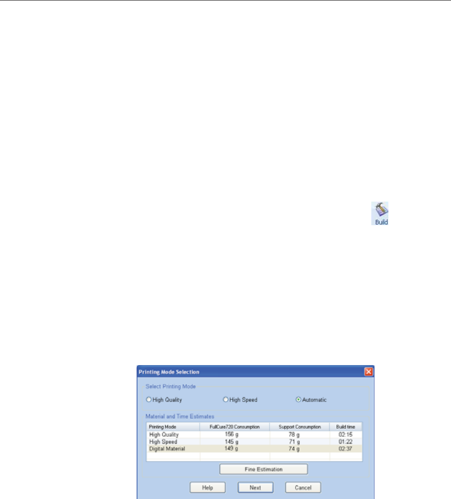
Using Objet Studio
5–48 DOC08010 Rev. A (DRAFT 1)
E-mailing
Objet Digital
Files
YouȱcanȱeasilyȱeȬmailȱobjdfȱfilesȱusingȱMicrosoft®ȱOfficeȱOutlook®.ȱSendingȱ
objdfȱfilesȱisȱrecommendedȱ(insteadȱofȱstlȱfiles)ȱbecauseȱtheȱsizeȱofȱaȱfileȱisȱ
typicallyȱreducedȱbyȱmoreȱthanȱhalf.ȱAnȱaddedȱbenefitȱisȱthatȱtheȱobjdfȱfileȱ
containsȱtheȱmodelȬmaterialȱinformationȱforȱtheȱobject.
To e-mail a file:
1. FromȱtheȱToolsȱmenu,ȱselectȱEmail Objet Digital File.
OutlookȱopensȱwithȱtheȱfileȱattachedȱandȱSubjectȱdetailsȱaddedȱtoȱtheȱ
eȬmailȱform.
2. EnterȱtheȱeȬmailȱaddressȱandȱsendȱtheȱfile.
Printing the
Tray File Whenȱaȱtrayȱisȱreadyȱtoȱbeȱprinted,ȱitȱisȱplacedȱinȱtheȱJobsȱQueue.ȱWhenȱtheȱ
jobȱreachesȱtheȱheadȱofȱtheȱqueue,ȱObjetȱStudioȱpreȬprocessesȱtheȱtrayȱfileȱtoȱ
createȱslices,ȱandȱfeedsȱthemȱtoȱtheȱ3Dȱprinter.
To send the tray to the print queue:
1. OnȱtheȱTrayȱSettingsȱribbon,ȱBuildȱProcessȱgroup,ȱclickȱ.
•Ifȱprintingȱtheȱtrayȱrequiresȱȱ(DigitalȱMaterialȱmode),ȱtheȱJobȱ
Summaryȱdialogȱboxȱopens.ȱ
Figure 5-69: Job Summary when printing with multiple model materials
Note:The values displayed are the result of a quick calculation, and
represent a rough estimate of the materials and time input required to
print the job. For a more accurate calculation, click Fine Estimation.
Continueȱwithȱstepȱ4ȱonȱpage 5Ȭ50.
•Ifȱprintingȱtheȱtrayȱrequiresȱonlyȱoneȱmodelȱmaterial,ȱtheȱPrintingȱ
ModeȱSelectionȱdialogȱboxȱopens.
Figure 5-70: Printing Mode Selection dialog box
Note:The values displayed are the result of a quick calculation, and
represent a rough estimate of the materials and time input required to
print the job. For a more accurate calculation, click Fine Estimation.
Printing-Mode
Selection 2. Selectȱtheȱappropriateȱprintingȱmode.
•IfȱyouȱrequireȱtheȱjobȱtoȱbeȱprintedȱinȱHighȱQualityȱmode,ȱselectȱthisȱ
option.
Note:The availability of High Quality mode depends on the material
selected.
•IfȱyouȱrequireȱtheȱjobȱtoȱbeȱprintedȱinȱHighȱSpeedȱmode,ȱselectȱthisȱ
option.
•IfȱyouȱdoȱnotȱrequireȱtheȱjobȱtoȱbeȱprintedȱeitherȱinȱHighȱQualityȱorȱ
HighȱSpeedȱmode,ȱselectȱAutomatic.ȱ
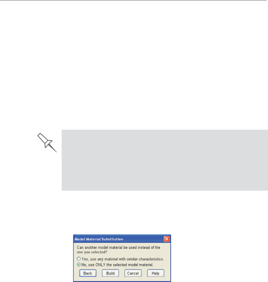
DOC08010 Rev. A (DRAFT 1) 5–49
Stratasys P750K User Guide
ThisȱsettingȱenablesȱtheȱStratasysȱsoftwareȱtoȱdetermineȱ(justȱbeforeȱ
printing)ȱtheȱmostȱefficientȱwayȱtoȱprintȱtheȱtray.ȱDigitalȱMaterialȱmodeȱ
isȱusedȱifȱthisȱremovesȱtheȱneedȱtoȱperformȱtheȱMaterialȱReplacementȱ
procedure.ȱOtherwise,ȱHighȱSpeedȱmodeȱisȱused.
Forȱexample,ȱifȱprintingȱtheȱtrayȱrequiresȱonlyȱoneȱofȱtheȱmodelȱ
materialsȱloadedȱinȱtheȱprinter,ȱonlyȱtheȱtwoȱprintȱheadsȱusingȱthatȱ
materialȱareȱusedȱtoȱprintȱmodels—DigitalȱMaterialȱmode.ȱ(Highȱ
QualityȱandȱHighȱSpeedȱmodesȱcallȱforȱprintingȱmodelȱmaterialȱwithȱ
fourȱheads,ȱwhichȱwouldȱrequireȱyouȱtoȱperformȱtheȱMaterialȱ
Replacementȱprocedure.)
Onȱtheȱotherȱhand,ȱifȱprintingȱtheȱtrayȱcanȱbeȱdoneȱusingȱfourȱprintȱ
headsȱwithoutȱrunningȱtheȱMaterialȱReplacementȱprocedure,ȱHighȱ
Speedȱmodeȱisȱused.ȱThisȱisȱpossibleȱifȱallȱprintȱheadsȱareȱsuppliedȱwithȱ
oneȱmodelȱmaterial,ȱorȱifȱyouȱallowȱprintingȱwithȱanȱarbitraryȱmixtureȱ
ofȱsimilarȱmaterialsȱ(seeȱbelow).
3. ClickȱNext.
TheȱModelȱMaterialȱSubstitutionȱdialogȱboxȱopens—ifȱthisȱisȱrelevantȱforȱ
theȱtray.ȱ(Ifȱnot,ȱtheȱJobȱSummaryȱdialogȱboxȱopens—continueȱwithȱ
step 4.)
Model Material
Substitution
Figure 5-71: Model Material Substitution dialog box
Ifȱyouȱallowȱtheȱuseȱofȱsubstituteȱmodelȱmaterials,ȱtheȱprinterȱwillȱuseȱ
differentȱmaterialsȱwhoseȱcharacteristicsȱ(strength,ȱflexibility,ȱetc.)ȱareȱ
similarȱtoȱthoseȱofȱtheȱmaterialȱyouȱassignedȱtoȱtheȱobjectȱwhenȱ
designingȱtheȱbuildȱtray—underȱtheȱfollowingȱconditions:
•Theȱmaterialȱyouȱassignedȱisȱnotȱinstalledȱinȱtheȱprinterȱatȱtheȱtimeȱ
ofȱprinting.
Inȱthisȱcase,ȱtheȱtrayȱisȱprintedȱwithȱeitherȱoneȱorȱtwoȱsubstituteȱ
materialsȱ(dependingȱonȱtheȱmaterialsȱinstalledȱinȱtheȱprinterȱatȱtheȱ
timeȱofȱprinting).ȱIfȱpossible,ȱHighȱSpeedȱmodeȱisȱused.
•Inȱadditionȱtoȱtheȱmaterialȱyouȱselected,ȱthereȱisȱanotherȱ(similar)ȱ
materialȱinstalledȱinȱtheȱprinterȱatȱtheȱtimeȱofȱprinting.
Inȱthisȱcase,ȱHighȱSpeedȱmodeȱisȱused,ȱbyȱprintingȱwithȱaȱmixtureȱofȱ
theȱtwoȱmaterialsȱ(asȱifȱtheyȱwereȱtheȱsameȱmaterial).
Model Quality When Digital Material Mode is Used
¾Near-high-quality is achieved for most models.
¾
If
all
objects on the tray are inserted from
individual stl files
, they are
printed with the standard resolution of 600 dpi (dots per inch) along the
Y-axis—unless glossy finish is required (see “Surface Finish” on page 23).
¾If there is an assembly on the tray, all of the models on the tray are
printed with a resolution of 300 dpi along the Y-axis.
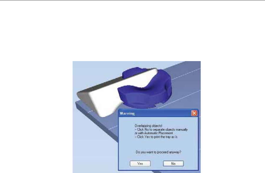
Using Objet Studio
5–50 DOC08010 Rev. A (DRAFT 1)
4. ClickȱBuild.
Ifȱtheȱbuildȱtrayȱfileȱhasȱnotȱbeenȱsaved,ȱtheȱSaveȱAsȱdialogȱboxȱopensȱforȱ
youȱtoȱsaveȱitȱnow.
ObjetȱStudioȱchecksȱifȱthereȱisȱaȱproblemȱwithȱtheȱpositioningȱofȱobjectsȱ
onȱtheȱtray.ȱIfȱso,ȱtheȱaffectedȱobjectsȱareȱdisplayedȱwithȱspecialȱcolorsȱ
(seeȱ“TrayȱValidation”ȱonȱpage 45),ȱandȱaȱwarningȱmessageȱappears.
Figure 5-72: Tray validation warning message
•ToȱcancelȱtheȱBuildȱcommandȱsoȱyouȱcanȱcorrectȱtheȱproblem,ȱclickȱ
No.
•Toȱprintȱtheȱmodelsȱasȱtheyȱareȱpositionedȱonȱtheȱtray,ȱclickȱYes.
TheȱJobȱManagerȱscreenȱopens,ȱsoȱyouȱcanȱmonitorȱtheȱprogressȱofȱyourȱ
trays—before,ȱduring,ȱandȱafterȱprinting.ȱSeeȱ“Monitoringȱandȱ
ManagingȱPrintȱJobs”ȱonȱpage 68.
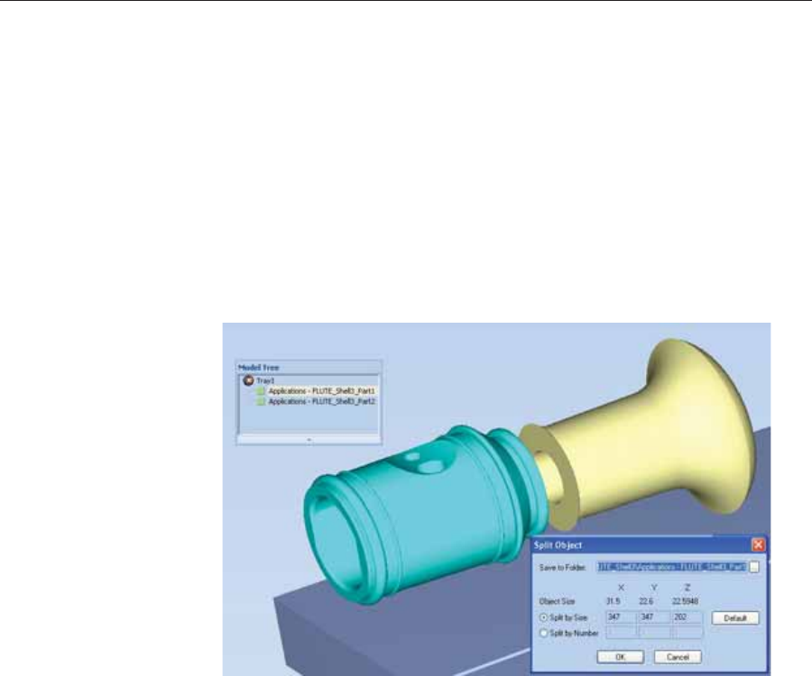
DOC08010 Rev. A (DRAFT 1) 5–51
Stratasys P750K User Guide
Applying Additional Objet Studio Features
Dividing
Objects YouȱcanȱuseȱtheȱSplitȱObjectȱfeatureȱtoȱproduceȱobjectsȱlargerȱthanȱtheȱtrayȱ
areaȱbyȱdividingȱtheȱmodelȱintoȱseparateȱparts.ȱWithȱthisȱfeature,ȱyouȱ
produceȱonlyȱaȱspecificȱsectionȱofȱaȱmodel.
To split an object:
1. Selectȱtheȱobject.
2. FromȱtheȱObjectȱmenu,ȱselectȱSplit.
3. InȱtheȱSplitȱObjectȱdialogȱbox,ȱenterȱtheȱvaluesȱtoȱdetermineȱhowȱObjetȱ
Studioȱwillȱdivideȱtheȱobject.ȱYouȱcanȱdivideȱanȱobjectȱalongȱanyȱofȱitsȱ
axes,ȱbyȱenteringȱeitherȱexactȱmeasurementsȱorȱtheȱnumberȱofȱparts.
Figure 5-73: Split Object dialog box
4. InȱSaveȱtoȱFolder,ȱenterȱtheȱfolderȱname.
5. ClickȱOK.
Theȱcompositeȱpartsȱareȱsavedȱasȱnewȱstlȱfilesȱwithȱ“Partȱ1,”ȱ“Partȱ2,”ȱ
etc.,ȱaddedȱtoȱtheȱoriginalȱfileȱname.
Note: Before printing the newly created stl files, it is recommended that you
check them for defects in an STL-repair application, such as
Magics™, by Materialise®.
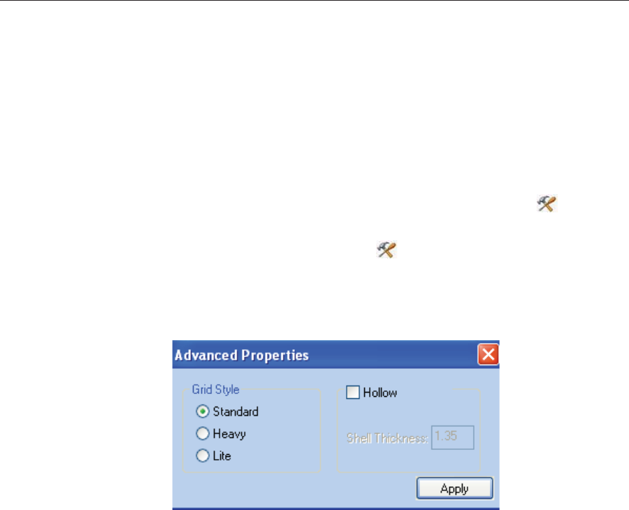
Using Objet Studio
5–52 DOC08010 Rev. A (DRAFT 1)
Choosing the
Support
Strength
Whenȱproducingȱmodels,ȱsupportȱmaterialȱfillsȱsomeȱhollowȱandȱemptyȱ
sectionsȱ(seeȱ“ModelȱOrientation”ȱonȱpage 26).ȱObjetȱStudioȱallowsȱyouȱtoȱ
adjustȱtheȱstrengthȱofȱtheȱstructureȱformedȱwithȱtheȱsupportȱmaterial.ȱThisȱ
adjustmentȱisȱusefulȱwhenȱproducingȱeitherȱlarge/massiveȱmodelsȱorȱsmall/
delicateȱmodels.ȱForȱmostȱpurposes,ȱtheȱdefaultȱsettingȱprovidesȱadequateȱ
supportȱstrength.
To change the strength of the support structure used when printing a
model:
1. Selectȱaȱmodelȱonȱtheȱtray.
2. OnȱtheȱModelȱSettingsȱribbon,ȱinȱtheȱOptionsȱgroup,ȱclickȱ.
or—
•OnȱtheȱModelȱToolbar,ȱclickȱ.
or—
•FromȱtheȱrightȬclickȱcontextȱmenu,ȱselectȱAdvanced Properties.
TheȱAdvancedȱPropertiesȱdialogȱboxȱopens.
Figure 5-74: Advanced Properties dialog box
3. InȱtheȱGridȱStyleȱsection,ȱchooseȱtheȱsupportȱstrengthȱsuitableȱforȱtheȱ
selectedȱmodel.ȱYouȱcanȱselectȱaȱdifferentȱsupportȱstrengthȱforȱeachȱ
modelȱonȱtheȱtray.
•Standard—forȱmodelsȱneedingȱaverageȱsupportȱ(mostȱmodels).
•Heavy—forȱlargeȱmodelsȱneedingȱmuchȱsupport.
•Lite—forȱdelicateȱmodelsȱneedingȱlittleȱsupport.ȱ(Thisȱsettingȱmakesȱ
itȱeasyȱtoȱremoveȱtheȱsupportȱmaterial.)
Note: If an object is split into shells, the Advanced Properties enabled vary
with the object selection. If a single element is selected only Hollow
is enabled. If a group of elements is selected only Grid Style is
enabled.
4. ClickȱApply.
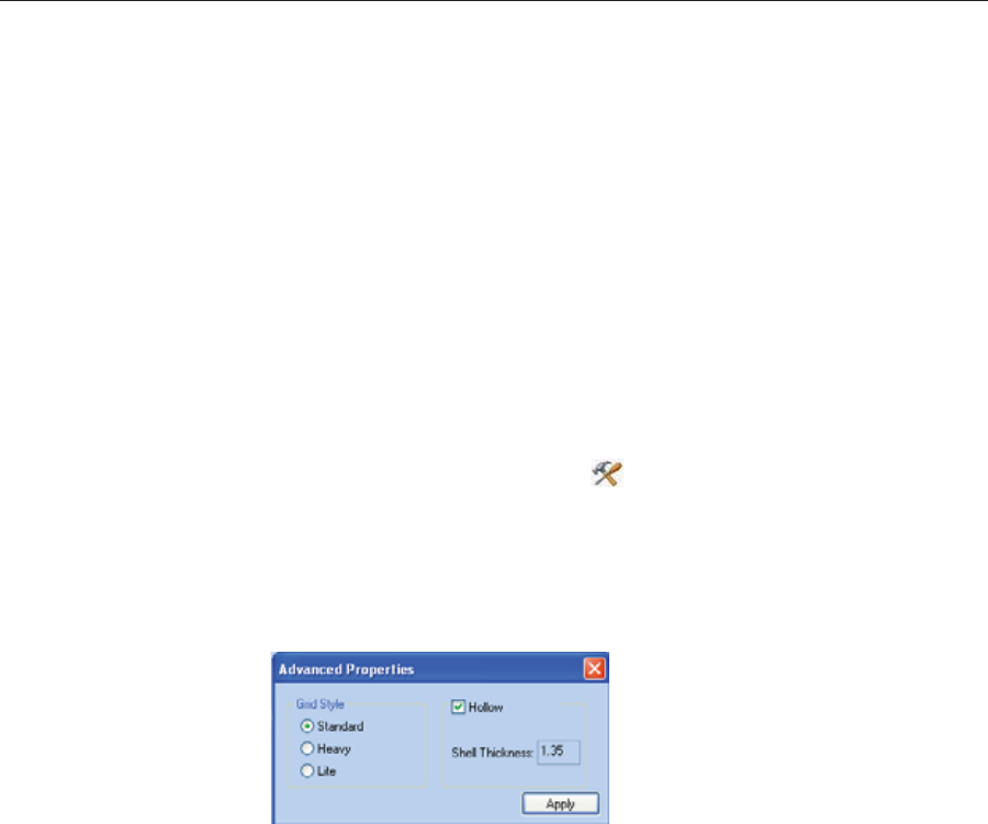
DOC08010 Rev. A (DRAFT 1) 5–53
Stratasys P750K User Guide
“Hollow”—
Filling Models
with Support
Material
Manyȱobjectsȱplacedȱonȱtheȱtrayȱfromȱstlȱfilesȱareȱ“solid.”ȱThisȱmeansȱthat,ȱ
whenȱprinted,ȱtheȱmodelȱwillȱbeȱcompletelyȱfilledȱwithȱmodelȱmaterial.ȱ
Often,ȱespeciallyȱwithȱlargeȱobjects,ȱthisȱisȱunnecessary.ȱInstead,ȱtheȱmodelȱ
canȱbeȱfilledȱwithȱsupportȱmaterial,ȱwhichȱisȱlessȱcostly.ȱItȱisȱalsoȱadvisableȱ
toȱfillȱmodelsȱwithȱsupportȱmaterialȱwhenȱpreparingȱthemȱforȱinvestmentȱ
casting,ȱsinceȱthisȱmaterialȱburnsȱoffȱmoreȱquicklyȱduringȱtheȱprocessȱofȱ
makingȱtheȱcast.
ObjetȱStudioȱenablesȱyouȱtoȱprintȱobjectsȱonȱtheȱtrayȱwithȱanȱouterȱshellȱofȱ
modelȱmaterialȱandȱaȱcenterȱfilledȱwithȱsupportȱmaterial.ȱWhenȱusingȱthisȱ
feature,ȱcalledȱ“Hollow,”ȱtheȱthicknessȱofȱtheȱshellȱshouldȱbeȱnoȱlessȱthanȱ
0.5ȱmillimeters.
To use the Hollow feature:
1. Selectȱaȱmodelȱonȱtheȱtray.
or—
•OnȱtheȱModelȱToolbar,ȱclickȱ.
or—
•FromȱtheȱrightȬclickȱcontextȱmenu,ȱselectȱAdvanced Properties.
TheȱAdvancedȱPropertiesȱdialogȱboxȱopens.
2. SelectȱHollow.
Figure 5-75: Advanced Properties dialog box
3. Setȱtheȱshellȱthickness,ȱinȱmillimeters.
4. ClickȱApply.
Note: There is no change in the display of objects in Objet Studio when
Hollow is selected.
To inspect, change or cancel the Hollow setting:
1. Selectȱaȱmodelȱonȱtheȱtray.
2. AccessȱtheȱAdvancedȱPropertiesȱdialogȱbox,ȱasȱabove.
3. IfȱyouȱchangeȱorȱcancelȱtheȱHollowȱsetting,ȱclickȱApply.
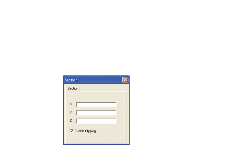
Using Objet Studio
5–54 DOC08010 Rev. A (DRAFT 1)
Displaying the
Cross Section
of Objects
TheȱSectionȱfeatureȱenablesȱyouȱtoȱviewȱtheȱinteriorȱofȱanȱobjectȱbyȱ“slicing”ȱ
itȱonȱanyȱaxis.ȱYouȱcanȱthenȱmanipulateȱtheȱobjectȱtoȱinspectȱtheȱinteriorȱ
fromȱdifferentȱangles.ȱThisȱmayȱbeȱimportantȱforȱdecidingȱonȱtheȱtypeȱofȱ
supportȱnecessaryȱwhenȱproducingȱtheȱmodelȱ(seeȱ“ChoosingȱtheȱSupportȱ
Strength”ȱonȱpage 52).ȱDisplayingȱanȱobject’sȱcrossȱsectionȱonlyȱaffectsȱhowȱ
theȱtrayȱisȱdisplayedȱonȱtheȱscreen;ȱitȱdoesȱnotȱchangeȱtheȱobjectȱitself.
To display a cross section of the tray:
1. FromȱtheȱToolsȱmenu,ȱselectȱSection.
TheȱSectionȱdialogȱboxȱopens.
Figure 5-76: Section dialog box
2. SelectȱEnable Clipping.
3. UseȱtheȱsliderȱcontrolsȱforȱtheȱXȬ,ȱYȬ,ȱandȱZȬaxesȱtoȱcutȱtheȱtrayȱsoȱthatȱ
youȱseeȱtheȱcrossȱsectionȱyouȱwant.
Figure 5-77: Whole view Figure 5-78: Cross-section view, after
using the Z-slider
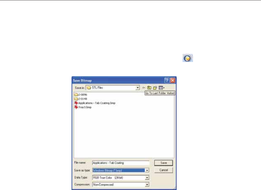
DOC08010 Rev. A (DRAFT 1) 5–55
Stratasys P750K User Guide
Saving the
Screen Display
as an
Image File
Youȱcanȱsaveȱtheȱimageȱdisplayedȱinȱtheȱactiveȱviewingȱscreenȱasȱaȱgraphicȱ
file.
To save the screen display as an image:
1. PressȱCtrl+B.
or—ȱ
FromȱtheȱObjetȱStudioȱCommandsȱmenuȱ,ȱselectȱSave Bitmap.
TheȱSaveȱBitmapȱdialogȱboxȱopens.
Figure 5-79: Save Bitmap dialog box
2. Atȱtheȱtopȱofȱtheȱdialogȱbox,ȱselectȱtheȱappropriateȱfolder.
3. Atȱtheȱbottomȱofȱtheȱdialogȱbox,ȱenterȱaȱfileȱname.
4. OpenȱtheȱSaveȱasȱtypeȱdropȬdownȱlist,ȱandȱselectȱtheȱfileȱformat.
5. ClickȱSave.

Using Objet Studio
5–56 DOC08010 Rev. A (DRAFT 1)
Exporting and
Importing
Objet Build
Trays
WhenȱyouȱsaveȱbuildȱtraysȱinȱObjetȱStudio,ȱtheyȱareȱsavedȱasȱobjtfȱfiles.ȱ
TheseȱfilesȱcontainȱinstructionsȱtoȱObjetȱStudioȱandȱtoȱStratasysȱprintersȱforȱ
displayingȱandȱproducingȱtheȱstlȱfilesȱusedȱonȱtheȱtray.ȱToȱconvenientlyȱ
saveȱallȱofȱtheȱfilesȱasȱtheyȱareȱpositionedȱonȱtheȱbuildȱtray,ȱforȱstoringȱtheȱ
job,ȱorȱforȱtransferringȱitȱtoȱanotherȱlocation,ȱObjetȱStudioȱcompressesȱthemȱ
intoȱoneȱobjzfȱfile.ȱToȱlaterȱuseȱtheȱobjzfȱfile,ȱtheȱfileȱmustȱfirstȱbeȱexpandedȱ
inȱObjetȱStudioȱandȱitsȱcomponentȱfilesȱsaved.
Note: If you export an objzf file containing a stl file originally saved as read-
only, you cannot open (import) this objzf file to the folder where the
read-only stl file is saved.
To create an objzf file:
1. FromȱtheȱObjetȱStudioȱCommandsȱmenuȱ,ȱselectȱExport Packed Job.
TheȱSaveȱAsȱdialogȱboxȱopens.
2. Selectȱtheȱappropriateȱfolderȱandȱchangeȱtheȱfileȱnameȱ(ifȱnecessary).
3. ClickȱSave.
To open an objzf file:
¾DoubleȬclickȱonȱtheȱobjtfȱfile.
or—
1. FromȱtheȱObjetȱStudioȱCommandsȱmenuȱ,ȱselectȱImport Packed Job.
2. InȱtheȱOpenȱdialogȱbox,ȱdisplayȱtheȱappropriateȱfolderȱandȱselectȱtheȱ
file.
3. InȱtheȱBrowseȱforȱFolderȱdialogȱbox,ȱdisplayȱtheȱfolderȱinȱwhichȱyouȱ
wantȱObjetȱStudioȱtoȱexpandȱtheȱcompressedȱfile,ȱandȱclickȱOK.
Theȱobjtfȱfileȱandȱassociatedȱstlȱfilesȱareȱexpandedȱandȱplacedȱinȱtheȱ
selectedȱfolder,ȱandȱtheȱtrayȱisȱdisplayedȱinȱObjetȱStudio.
Note: You can also export a print job as an objzf file from the Job Manager
screen—see “Exporting Jobs (objzf)” on page 80.
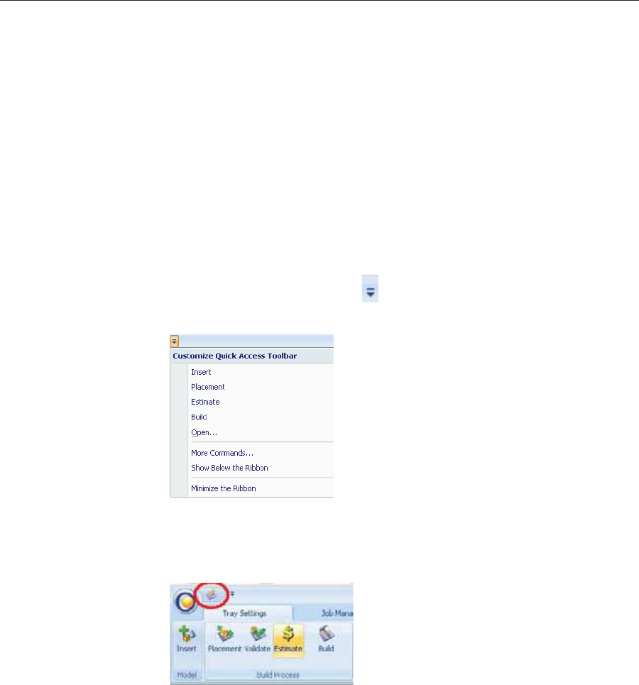
DOC08010 Rev. A (DRAFT 1) 5–57
Stratasys P750K User Guide
Customizing
Objet Studio
YouȱcanȱcustomizeȱObjetȱStudioȱtoȱsuitȱyourȱparticularȱworkingȱneedsȱandȱ
preferences.ȱFeaturesȱthatȱyouȱcanȱcustomizeȱinclude:
•CreatingȱaȱquickȬaccessȱtoolbarȱforȱfrequentlyȱusedȱcommands.
•ChangingȱtheȱpositionȱofȱtheȱQuickȱAccessȱtoolbar.
•Minimizingȱtheȱribbon.
•ChangingȱtheȱObjetȱStudioȱcolorȱtheme.
•Configuringȱdefaultȱsettingsȱforȱobjectsȱplacedȱonȱtheȱbuildȱtray.
Creating a
Quick Access
Toolbar
AsȱyouȱworkȱwithȱObjetȱStudio,ȱyouȱmayȱuseȱcertainȱcommandsȱfrequently.ȱ
YouȱcanȱcreateȱaȱquickȬaccessȱtoolbarȱtoȱmakeȱyourȱworkȱeasier.ȱ
To create a quick-access toolbar:
1. Aboveȱtheȱribbonȱtabs,ȱclickȱ.
TheȱCustomizeȱQuickȱAccessȱToolbarȱmenuȱopens.
Figure 5-80: Customize Quick Access Toolbar menu
2. Selectȱaȱcommandȱyouȱwantȱtoȱaddȱtoȱtheȱtoolbar.
Anȱiconȱforȱtheȱselectedȱcommandȱisȱaddedȱtoȱtheȱtoolbar.ȱ
Figure 5-81: Quick Access toolbar
Toȱaddȱanotherȱcommand,ȱrepeatȱtheȱaboveȱprocedure.
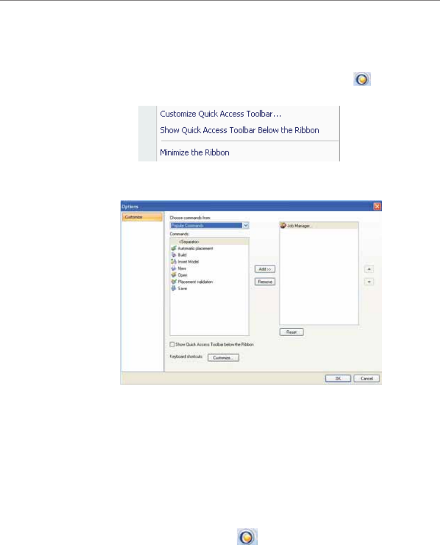
Using Objet Studio
5–58 DOC08010 Rev. A (DRAFT 1)
3. Toȱchooseȱfromȱaȱwiderȱrangeȱofȱcommands:
•FromȱtheȱCustomizeȱQuickȱAccessȱToolbarȱmenuȱ(seeȱfigure 5Ȭ80ȱonȱ
page 57),ȱselectȱMore Commands.
or—
•RightȬclickȱonȱtheȱObjetȱStudioȱCommandsȱiconȱ,ȱorȱelsewhereȱ
onȱtheȱribbon,ȱandȱselectȱCustomize Quick Access Toolbar.
Figure 5-82: Right-click ribbon menu
TheȱOptionsȱdialogȱboxȱopens.
Figure 5-83: Quick Access Toobar Options dialog box
4. OpenȱtheȱdropȬdownȱlistȱandȱselectȱeitherȱPopular Commandsȱorȱ
Commands not on the Ribbon.ȱ
5. SelectȱaȱcommandȱandȱclickȱAdd.
6. ClickȱOK.
Hiding the
Ribbon Toȱmakeȱmoreȱroomȱforȱdisplayingȱtheȱbuildȱtray,ȱyouȱcanȱhideȱtheȱObjetȱ
Studioȱribbons.
To hide the ribbons:
1. RightȬclickȱanywhereȱonȱtheȱribbonȱorȱonȱtheȱmenuȱbar,ȱorȱinȱtheȱObjetȱ
StudioȱCommandsȱmenuȱ.
2. SelectȱMinimize the Ribbon.
Theȱribbonsȱdisappear,ȱbutȱyouȱcanȱtemporarilyȱdisplayȱtheȱribbonȱ
iconsȱbyȱclickingȱTray Settings orȱJob Managerȱonȱtheȱmenuȱbar.ȱWhenȱ
youȱnextȱclickȱoutsideȱofȱtheȱribbon,ȱitȱdisappearsȱagain.
To return the permanent ribbon display:
¾RepeatȱtheȱstepsȱaboveȱtoȱcancelȱMinimizeȱtheȱRibbon.
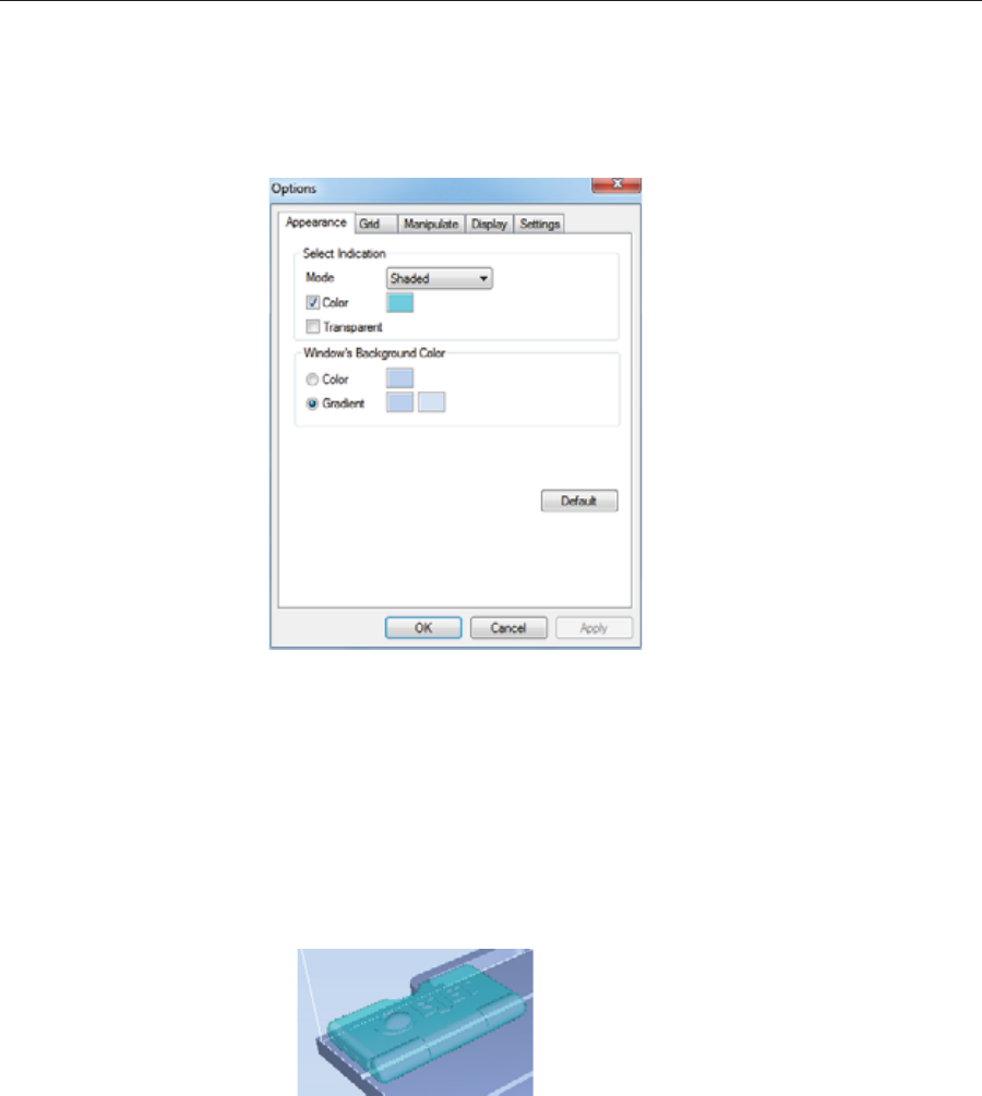
DOC08010 Rev. A (DRAFT 1) 5–59
Stratasys P750K User Guide
Display Colors YouȱcanȱcustomizeȱsomeȱofȱtheȱcolorsȱusedȱforȱdisplayingȱObjetȱStudioȱ
screensȱandȱforȱdisplayingȱobjectsȱonȱtheȱbuildȱtray.
To change the colors used in Objet Studio screens:
1. FromȱtheȱToolsȱmenu,ȱselectȱOptions.
Figure 5-84: Display settings
2. InȱtheȱAppearanceȱtabȱofȱtheȱOptionsȱdialogȱbox,ȱyouȱcanȱconfigureȱtheȱ
display.
•TheȱModeȱselectionȱdeterminesȱhowȱmodelsȱappearȱonȱtheȱbuildȱ
tray.ȱTheȱdefaultȱmethodȱforȱdisplayingȱmodelsȱonȱtheȱbuildȱtrayȱisȱ
asȱsolidȱ(“shaded”)ȱobjects.ȱTheȱotherȱoptionsȱareȱWireFrameȱandȱ
Points.
•IfȱShadedȱisȱselected,ȱyouȱcanȱdisplayȱtheȱmodelȱonȱtheȱtrayȱasȱaȱseeȬ
throughȱobject.
Figure 5-85: Transparent display
•DoubleȬclickȱtheȱcolorȱpatchesȱtoȱcustomizeȱcolors.
•TheȱWindowsȱBackgroundȱColorȱsettingsȱenableȱyouȱtoȱchangeȱtheȱ
colorȱbehindȱtheȱbuildȱtray—withȱeitherȱaȱsolidȱorȱaȱtwoȬcolorȱ
gradient.
•Toȱreturnȱtoȱtheȱdefaultȱdisplayȱsettings,ȱclickȱDefault.
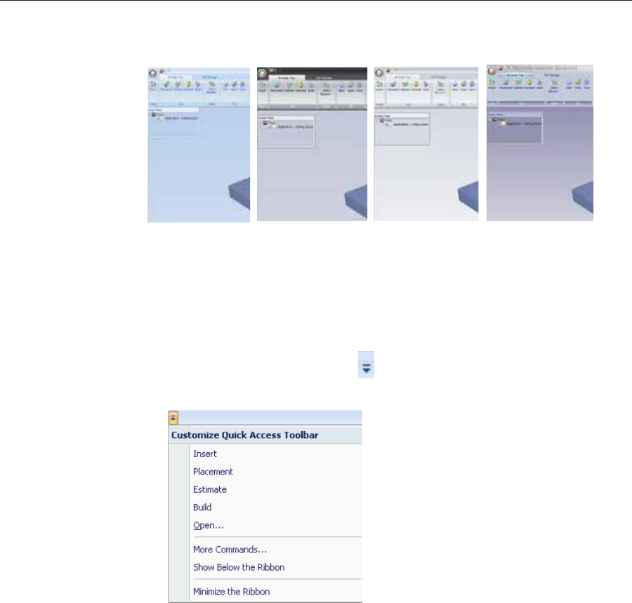
Using Objet Studio
5–60 DOC08010 Rev. A (DRAFT 1)
Changing Color
Themes ObjetȱStudioȱoffersȱaȱchoiceȱofȱfourȱbackgroundȱcolorȱthemes—blue,ȱblack,ȱ
silverȱandȱaqua.ȱ
Figure 5-86: Background color themes
To change the color theme:
¾FromȱtheȱStyleȱmenu,ȱselectȱoneȱofȱtheȱoptions.
Keyboard
Shortcuts Youȱcanȱdefineȱshortcutȱkeysȱforȱfrequentlyȱusedȱcommands.
To define shortcut keys:
1. Aboveȱtheȱribbonȱtabs,ȱclickȱ.
TheȱCustomizeȱQuickȱAccessȱToolbarȱmenuȱopens.
Figure 5-87: Customize Quick Access Toolbar menu
2. SelectȱMore Commands.
TheȱOptionsȱdialogȱboxȱopensȱ(seeȱfigure 5Ȭ83ȱonȱpage 58).
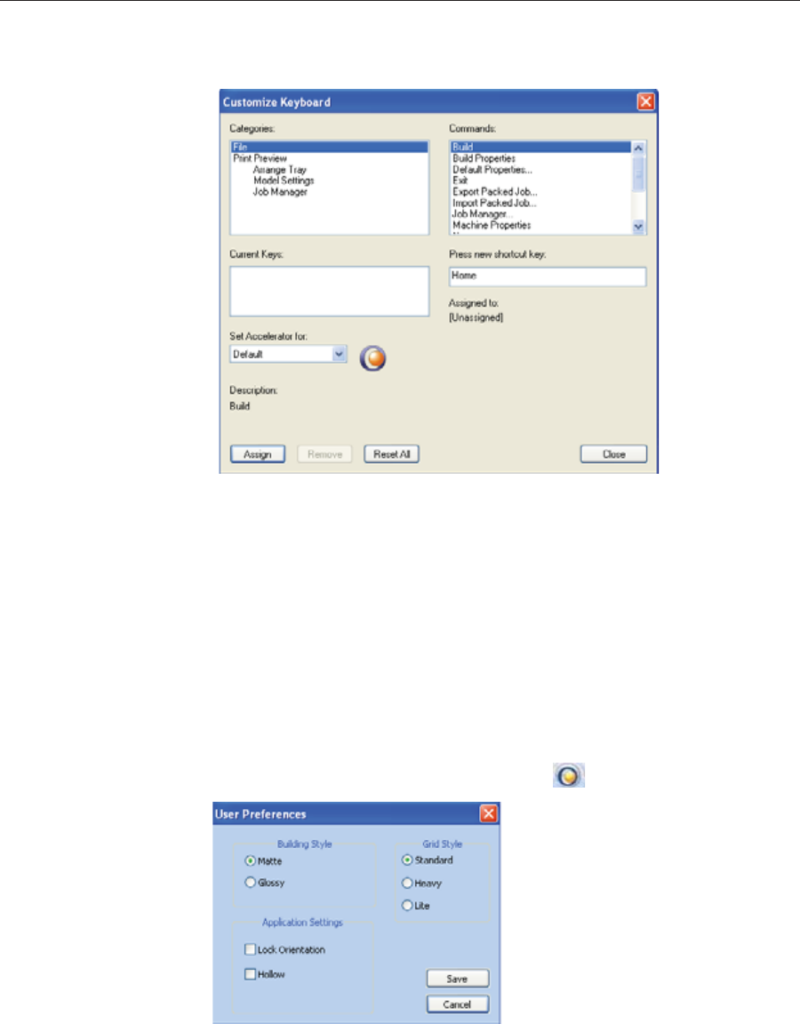
DOC08010 Rev. A (DRAFT 1) 5–61
Stratasys P750K User Guide
3. ClickȱCustomize.
TheȱCustomizeȱKeyboardȱdialogȱboxȱappears.
Figure 5-88: Customize Keyboard dialog box
4. SelectȱcommandȱCategoriesȱtoȱdisplayȱallȱtheȱcommandsȱinȱthatȱ
category,ȱforȱexample,ȱallȱtheȱModelȱSettingsȱcommands.ȱ
Currentȱshortcutȱkeysȱareȱdisplayed.
5. Enterȱtheȱshortcutȱkeyȱinȱthe Pressȱnewȱshortcutȱkeyȱfield,ȱandȱclickȱ
Assign.
6. Ifȱyouȱwantȱtoȱredefineȱallȱshortcutȱkeys,ȱclickȱReset All.
Setting User
Preferences YouȱcanȱchangeȱseveralȱObjetȱStudioȱsettingsȱthatȱaffectȱobjectsȱplacedȱonȱ
theȱbuildȱtray.
To change default settings:
¾FromȱtheȱObjetȱStudioȱCommandsȱmenuȱ,ȱselectȱUser Preferences.
Figure 5-89: Setting work preferences
•BuildingȱStyle—seeȱ“SurfaceȱFinish”ȱonȱpage 23.
•GridȱStyle—seeȱ“UsingȱaȱGridȱtoȱPositionȱObjects”ȱonȱpage 30.
•ApplicationȱSettings—seeȱ“ChoosingȱtheȱSupportȱStrength”ȱonȱpage 52,ȱ
andȱ“FreezingȱModelȱOrientation”ȱonȱpage 37.
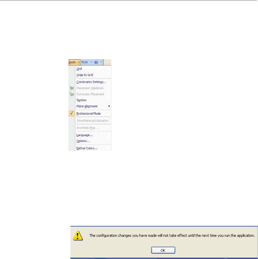
Using Objet Studio
5–62 DOC08010 Rev. A (DRAFT 1)
Professional Mode Features
SomeȱadvancedȱfeaturesȱofȱObjetȱStudioȱareȱonlyȱaccessibleȱinȱProfessionalȱ
Mode.ȱ
To see the current Objet Studio setting:
¾OpenȱtheȱToolsȱmenu.
Figure 5-90: Tools menu, showing Professional Mode selected
IfȱProfessionalȱModeȱisȱselected,ȱadvancedȱfeaturesȱareȱdisplayed.ȱ
To change the Professional Mode setting:
1. FromȱtheȱToolsȱmenu,ȱselectȱProfessional Mode.
Theȱfollowingȱmessageȱisȱdisplayed,ȱremindingȱyouȱthatȱtheȱchangeȱ
willȱonlyȱtakeȱeffectȱtheȱnextȱtimeȱyouȱopenȱObjetȱStudio—evenȱthoughȱ
theȱcheckȱmarkȱnextȱtoȱtheȱProfessionalȱModeȱoptionȱappearsȱ
immediately.
Figure 5-91: Configuration-change message
2. CloseȱandȱreȬopenȱObjetȱStudioȱtoȱuseȱtheȱProfessionalȱModeȱfeatures.
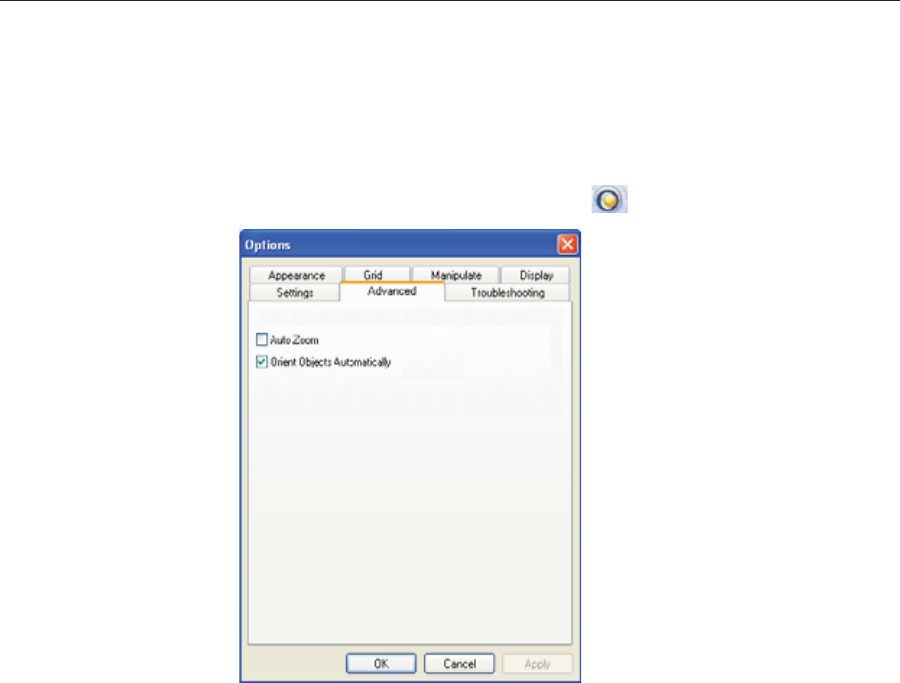
DOC08010 Rev. A (DRAFT 1) 5–63
Stratasys P750K User Guide
Default
Settings YouȱcanȱcontrolȱtheȱdefaultȱsettingsȱofȱseveralȱObjetȱStudioȱfeaturesȱfromȱ
theȱAdvancedȱtabȱofȱtheȱOptionsȱdialogȱbox.
To display the Options dialog box
¾FromȱtheȱToolsȱmenu,ȱselectȱOptions.
or—
InȱtheȱObjetȱStudioȱCommandsȱmenuȱ,ȱclickȱOptions.
Figure 5-92: Options dialog box, Advanced tab
Automatic
Orientation Byȱdefault,ȱwhenȱObjetȱStudioȱplacesȱobjectsȱonȱtheȱbuildȱtray,ȱitȱorientsȱ
themȱoptimally,ȱforȱtheȱshortestȱprintingȱtime.ȱIfȱnecessary,ȱyouȱcanȱchooseȱ
toȱcancelȱautomaticȱorientationȱeachȱtimeȱyouȱplaceȱanȱobjectȱonȱtheȱbuildȱ
trayȱ(seeȱ“AutomaticȱOrientation”ȱonȱpage 25).ȱInȱanyȱcase,ȱwhenȱobjectsȱ
areȱonȱtheȱbuildȱtray,ȱyouȱcanȱchangeȱtheirȱorientationȱmanuallyȱ(seeȱ
“ModelȱOrientation”ȱonȱpage 26.)ȱ
To change the default setting so that Automatic Orientation is disabled:
¾InȱtheȱAdvancedȱsectionȱofȱtheȱOptionsȱdialogȱbox,ȱclearȱtheȱcheckȱbox.
Automatic Zoom WhenȱAutoȱZoomȱisȱselectedȱinȱtheȱAdvancedȱsectionȱofȱtheȱOptionsȱdialogȱ
box,ȱtheȱdisplayȱzoomsȱin,ȱtoȱdisplayȱtheȱobjectsȱplacedȱonȱtheȱbuildȱtray.ȱ
Thisȱallowsȱyouȱtoȱcarefullyȱinspectȱandȱmanipulateȱtheȱobjects.
Byȱdefault,ȱthisȱfeatureȱisȱnotȱenabled.ȱInȱanyȱcase,ȱyouȱcanȱchangeȱtheȱ
zoomȱlevel,ȱasȱnecessaryȱ(seeȱ“ZoomȱOptions”ȱonȱpage 44).
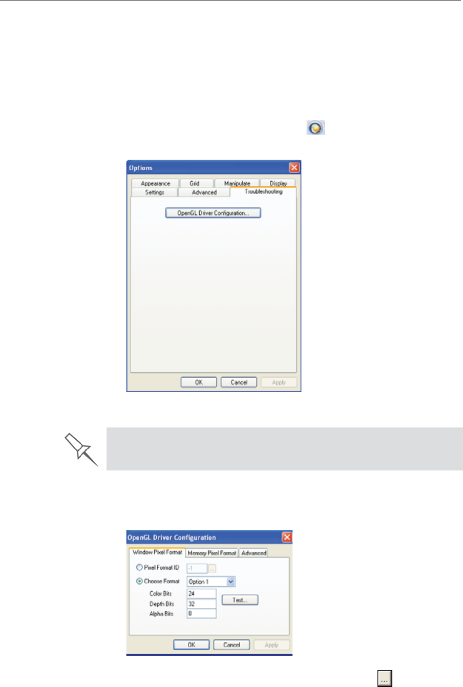
Using Objet Studio
5–64 DOC08010 Rev. A (DRAFT 1)
OpenGL Driver
Configuration TheȱOpenGLȱdriverȱdisplaysȱ3Dȱgraphicsȱonȱyourȱscreen.ȱThereȱisȱnormallyȱ
noȱreasonȱtoȱadjustȱitsȱsettings.ȱIfȱyouȱsuspectȱaȱproblemȱwithȱtheȱwayȱObjetȱ
Studioȱdisplaysȱobjects,ȱyouȱcanȱuseȱtheȱOpenGLȱDriverȱConfigurationȱtoolȱ
toȱcheckȱandȱconfigureȱtheȱdriverȱsettings.ȱ
To access the OpenGL Driver Configuration dialog box:
1. FromȱtheȱToolsȱmenu,ȱselectȱOptions.
or—
InȱtheȱObjetȱStudioȱCommandsȱmenuȱ,ȱclickȱOptions.
2. InȱtheȱOptionsȱdialogȱbox,ȱdisplayȱtheȱTroubleshootingȱtab.ȱ
Figure 5-93: Access to OpenGL Driver configuration
3. ClickȱOpenGL Driver Configuration.
TheȱdialogȱboxȱthatȱopensȱdisplaysȱdetailsȱofȱtheȱpixelȱformatȱIDȱ(index)ȱ
forȱtheȱwindowȱandȱtheȱmemory.
Figure 5-94: OpenGL Driver Configuration dialog box
Ifȱyouȱwantȱtoȱdisplayȱtheȱvaluesȱandȱchangeȱthem,ȱclickȱ.ȱAlternately,ȱ
youȱcanȱselectȱChoose Formatȱandȱchangeȱtheȱvaluesȱinȱthisȱdialogȱbox.
The Troubleshooting tab is only accessible when Professional Mode is
active (see “Professional Mode Features” on page 62).

DOC08010 Rev. A (DRAFT 1) 5–65
Stratasys P750K User Guide
To perform a test of the driver configuration and enter the suggested
pixel format ID:
1. SelectȱChoose Format.ȱ
2. ClickȱTest.
ObjetȱStudioȱreturnsȱtheȱrecommendedȱpixelȱformatȱID.
Figure 5-95: Recommended pixel format ID
3. ClickȱOK.ȱ
4. InȱtheȱOpenGLȱDriverȱConfigurationȱdialogȱboxȱ(figure 5Ȭ94),ȱselectȱPixel
Format IDȱandȱenterȱthisȱnumber.
5. ClickȱApply.
6. Displayȱtheȱotherȱpixelȱformatȱtab,ȱandȱrepeatȱthisȱprocedure.
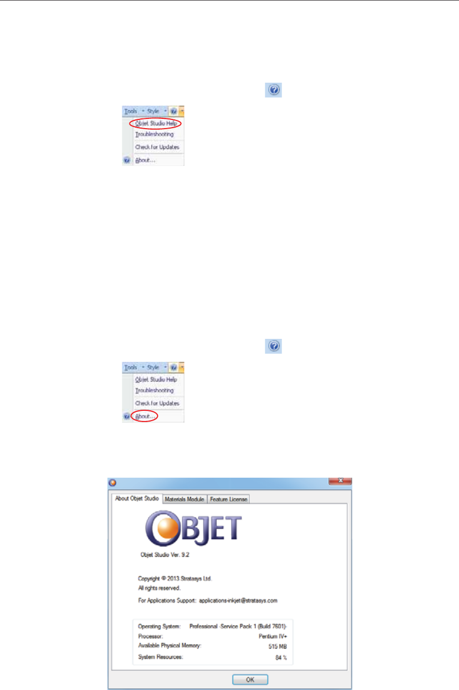
Using Objet Studio
5–66 DOC08010 Rev. A (DRAFT 1)
Getting Additional Objet Studio Assistance
ObjetȱStudioȱHelpȱprovidesȱonȬscreenȱinstructionsȱandȱinformation,ȱasȱyouȱ
work.
To view Objet Studio Help:
¾Onȱtheȱstandardȱtoolbar,ȱclickȱȱandȱthenȱclickȱObjet Studio Help.
Figure 5-96: Help options
Youȱcanȱalsoȱviewȱinformationȱonȱtheȱfollowingȱsubjects:
•Troubleshootingȱopensȱaȱlistȱofȱerrorȱmessagesȱandȱtheirȱ
explanations.
•CheckȱforȱUpdatesȱchecksȱifȱyouȱareȱusingȱtheȱlatestȱObjetȱStudioȱ
version.ȱ
Objet Studio Version, Material Module and Licensed Features
YouȱcanȱviewȱdetailsȱofȱtheȱObjetȱStudioȱversion,ȱtheȱmaterialȱmoduleȱ
installed,ȱandȱtheȱfeaturesȱavailableȱwithȱyourȱlicense.
To view details of your Objet Studio installation:
¾Onȱtheȱstandardȱtoolbar,ȱclickȱȱandȱthenȱclickȱAbout....
Figure 5-97: Displaying Objet Studio details
About Objet Studio
tab TheȱAboutȱObjetȱStudioȱtabȱshowsȱtheȱObjetȱStudioȱversionȱnumberȱandȱ
basicȱinformationȱaboutȱyourȱcomputer.
Figure 5-98: About Objet Studio tab
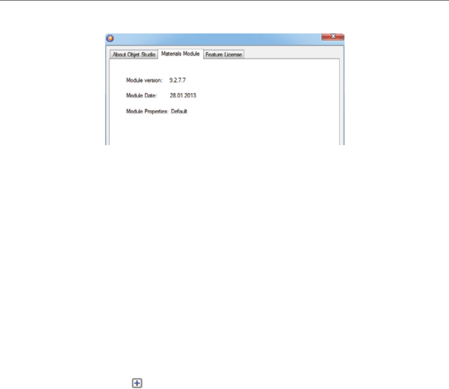
DOC08010 Rev. A (DRAFT 1) 5–67
Stratasys P750K User Guide
Materials Module
tab TheȱMaterialsȱModuleȱtabȱshowsȱdetailsȱofȱtheȱmaterialȱmoduleȱinstalled.
Figure 5-99: Materials Module tab
•Moduleȱversion
IfȱaȱMaterialsȱModuleȱupgradeȱ(patch)ȱwasȱinstalled,ȱtheȱnewȱMaterialsȱ
Moduleȱversionȱisȱdisplayed.ȱIfȱnoȱpatchesȱwereȱinstalled,ȱtheȱModuleȱ
versionȱisȱtheȱsameȱasȱtheȱObjetȱStudioȱversion.
•Moduleȱdate
IfȱaȱMaterialsȱModuleȱupgradeȱ(patch)ȱwasȱinstalled,ȱtheȱdateȱofȱitsȱ
creationȱisȱdisplayed.ȱIfȱnoȱpatchesȱwereȱinstalled,ȱtheȱModuleȱdateȱisȱtheȱ
dateȱofȱtheȱObjetȱStudioȱversion.
•Moduleȱproperties
IfȱaȱMaterialsȱModuleȱupgradeȱ(patch)ȱwasȱinstalled,ȱitsȱdescriptionȱisȱ
displayed.ȱIfȱnoȱpatchesȱwereȱinstalled,ȱ“Default”ȱisȱdisplayed.
Feature License
tab TheȱFeatureȱLicenseȱtabȱshowsȱtheȱObjetȱStudioȱfeaturesȱavailableȱwithȱyourȱ
license.
Figure 5-100: Feature License tab
Clickȱȱtoȱexpandȱtheȱdetailsȱforȱeachȱfeature.
•Modesȱshowsȱtheȱprintingȱmodesȱavailable.
Seeȱ“PrintingȱModes”ȱonȱpage 47.ȱ
•Materialsȱshowsȱbasicȱmodelȱmaterialsȱavailable.
•MixedȱTrayȱshowsȱifȱyourȱlicenseȱenablesȱprintingȱaȱbuildȱtrayȱ
containingȱobjects,ȱusingȱaȱdifferentȱmodelȱmaterialȱforȱeach.

Using Objet Studio
5–68 DOC08010 Rev. A (DRAFT 1)
Monitoring and Managing Print Jobs
InȱtheȱJobȱManagerȱscreenȱofȱObjetȱStudio,ȱyouȱmonitorȱandȱmanageȱjobsȱ
sentȱtoȱtheȱprinter.ȱThereȱareȱaȱfewȱdifferencesȱbetweenȱObjetȱStudioȱonȱ
clientȱworkstationsȱandȱonȱtheȱcomputerȱconnectedȱdirectlyȱtoȱtheȱ3Dȱ
printer—theȱserverȱworkstation.
•ObjetȱStudioȱinstalledȱonȱaȱclientȱcomputerȱonlyȱdisplaysȱtheȱqueueȱandȱ
statusȱforȱjobsȱsentȱtoȱtheȱ3Dȱprinterȱserverȱfromȱthatȱcomputer,ȱandȱitȱ
allowsȱtheȱuserȱtoȱeditȱonlyȱtheseȱjobs.ȱ
Note: If there are several Objet printers on the local network, client
computers can connect to any of them, but only one at a time.
•ObjetȱStudioȱinstalledȱonȱtheȱcomputerȱdirectlyȱconnectedȱtoȱaȱspecificȱ
3Dȱprinterȱ(server),ȱdisplaysȱtheȱqueueȱandȱstatusȱforȱallȱjobsȱsentȱtoȱthatȱ
3Dȱprinterȱbyȱtheȱserverȱandȱbyȱallȱclientȱcomputersȱonȱtheȱnetwork.ȱItȱ
alsoȱallowsȱeditingȱandȱmanipulationȱofȱallȱjobs,ȱandȱenablesȱreȬsendingȱ
previouslyȬprintedȱjobsȱtoȱtheȱprinter.
Job Manager
Screen TheȱJobȱManagerȱscreenȱonȱtheȱclientȱandȱserverȱworkstationsȱlooksȱ
identical.ȱTheȱonlyȱdifferenceȱisȱthatȱoptionsȱonlyȱrelevantȱtoȱtheȱserverȱ
workstationȱareȱdisabledȱforȱclientȱinstallations.
Figure 5-101: Job Manager screen
TheȱJobȱManagerȱscreenȱisȱdividedȱintoȱpanels:
•JobsȱQueue
•PrintingȱProgress
•History
•AvailableȱResources
•MaterialȱConsumption
•TrayȱPreview
•Waste
If Objet Studio is not connected to a printer (or printer server), you can
prepare tray files for any Objet printer. Later, these files can be used by
Objet Studio on the appropriate printer server.

DOC08010 Rev. A (DRAFT 1) 5–69
Stratasys P750K User Guide
Jobs Queue
Onȱtheȱserver,ȱtheȱ
JobsȱQueue
ȱlistsȱtheȱlastȱ15ȱjobsȱsentȱfromȱclientȱcomputers.ȱ
Onȱclientȱworkstations,ȱtheȱ
JobsȱQueue
ȱlistsȱjobsȱsentȱfromȱthatȱcomputerȱtoȱ
theȱprinterȱserver.ȱ
Informationȱforȱeachȱofȱtheȱqueuedȱjobsȱisȱdisplayed,ȱincludingȱtheȱjobȱstatus.
Inȱaddition,ȱtheȱfollowingȱinformationȱisȱdisplayed:
•Owner—theȱcomputerȱthatȱsentȱtheȱjob
•BuildȱTime—theȱestimatedȱbuildingȱtimeȱforȱtheȱjob
•ModelȱConsumption—theȱamountȱofȱmodelȱmaterialȱrequiredȱtoȱ
completeȱtheȱjob,ȱandȱtheȱamountȱactuallyȱusedȱtillȱnow
•SupportȱConsumption—theȱamountȱofȱsupportȱmaterialȱrequiredȱtoȱ
completeȱtheȱjob,ȱandȱtheȱamountȱactuallyȱusedȱtillȱnow
•PrintingȱMode—HS=HighȱSpeed,ȱHQ=HighȱQuality,ȱDM=Digitalȱ
Material
Printing Progress
Theȱ
Time
ȱpanelȱshowsȱprintingȱtimesȱandȱtheȱnumberȱofȱslicesȱsentȱtoȱtheȱprinter.
History TheȱHistoryȱpanelȱshowsȱinformationȱforȱtheȱlastȱ50ȱjobsȱandȱtheirȱfinalȱ
status.ȱYouȱcanȱdragȱaȱjobȱfromȱHistoryȱtoȱJobsȱQueueȱtoȱprintȱtheȱtrayȱagain.
Available
Resources TheȱAvailableȱResourcesȱpanelȱcontainsȱgraphicȱindicatorsȱthatȱshowȱtheȱ
amountȱofȱavailableȱprintingȱmaterialsȱremainingȱinȱtheȱprinter.*ȱ
Material
Consumption •Actual—theȱamountȱofȱmaterialȱusedȱtillȱnow
•Required—theȱamountȱofȱmaterialȱstillȱneededȱtoȱfinishȱtheȱjob
Tray Preview TheȱTrayȱPreviewȱpanelȱdisplaysȱtheȱbuildȱtrayȱviewȱofȱtheȱjobȱselectedȱinȱtheȱ
JobȱQueueȱorȱtheȱHistoryȱlist.ȱ
Onȱaȱserver,ȱyouȱcanȱopenȱanȱenlargedȱpreviewȱwindowȱbyȱclickingȱonȱtheȱ
TrayȱPreviewȱdisplayȱ(seeȱ“ExtendedȱTrayȱPreview”ȱonȱpage 78).
Waste IfȱyouȱmoveȱtheȱmouseȱoverȱtheȱWasteȱdisplay,ȱtheȱamountȱofȱwasteȱinȱtheȱ
containerȱisȱdisplayed.
Status Meaning
Waiting Printingȱofȱthisȱjobȱhasȱnotȱstarted.
Building Printingȱofȱthisȱjobȱisȱinȱprogress.
Stopped Printingȱofȱthisȱjobȱwasȱinterrupted.ȱPrintingȱcanȱlaterȱbeȱ
continuedȱ(Resume)ȱorȱbegunȱagainȱ(Restart).
Error Errorsȱoccurredȱduringȱtheȱprintingȱofȱthisȱjob,ȱandȱitȱwasȱ
placedȱinȱtheȱJobsȱQueueȱagain.
Editing ThisȱjobȱisȱnowȱbeingȱeditedȱinȱObjetȱStudio.
Spooling Theȱjobȱfileȱisȱbeingȱspooledȱinȱtheȱprinter.
Preprocessing
Theȱ3Dȱprinterȱisȱreadyingȱitselfȱforȱprinting:ȱtheȱcoverȱ
locks,ȱprintȱheadsȱwarmȱupȱandȱareȱputȱinȱstartingȱposition,ȱ
UVȱlamp
s
ȱ
areȱ
turnedȱon,ȱandȱtheȱbuildȱtrayȱlevelȱisȱ
adjusted.
OnȱSchedule Theȱjobȱisȱscheduledȱtoȱbeȱprintedȱatȱaȱspecifiedȱtime.
*ObjetȱStudioȱdisplaysȱtheȱweightȱofȱtheȱprintingȱmaterialsȱinȱbothȱcartridgesȱ
asȱlongȱasȱeachȱcartridgeȱcontainsȱmoreȱthanȱ100ȱgramsȱofȱmaterial.ȱTheȱ
weightȱunderȱ100ȱgramsȱisȱnotȱcalculatedȱandȱdisplayed.ȱHowever,ȱifȱaȱ
cartridgeȱcontainsȱlessȱthanȱ100ȱgramsȱofȱmaterial,ȱtheȱprinterȱusesȱit—asȱ
longȱasȱtheȱmaterialȱinȱtheȱotherȱcartridgeȱweighsȱmoreȱthanȱ100ȱgrams.ȱInȱ
anyȱcase,ȱtheȱweightȱofȱeachȱcartridgeȱisȱdisplayedȱinȱtheȱprinterȱapplication.
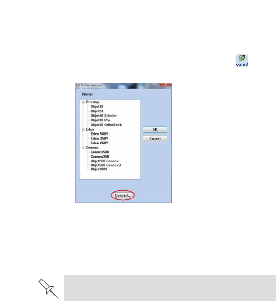
Using Objet Studio
5–70 DOC08010 Rev. A (DRAFT 1)
Setting the
Printer
Connection
WhenȱanȱObjetȱ3Dȱprinterȱisȱinstalled,ȱtheȱserverȱcomputerȱisȱconnectedȱtoȱ
thatȱprinter.ȱNormally,ȱthereȱshouldȱbeȱnoȱreasonȱtoȱchangeȱthisȱconnection.ȱ
Occasionally,ȱhowever,ȱyouȱmayȱneedȱtoȱresetȱtheȱconnection,ȱtoȱconnectȱ
theȱserverȱtoȱanotherȱprinter,ȱorȱtoȱuseȱObjetȱStudioȱinȱoffȬlineȱmodeȱ
(withoutȱaȱprinterȱconnection).
To set (or change) the printer connection:
1. OnȱtheȱJobȱManagerȱribbon,ȱinȱtheȱ3DȱPrinterȱgroup,ȱclickȱ.
2. InȱtheȱSetȱPrinterȱdialogȱbox,ȱclickȱConnect.
Figure 5-102: Connecting to a printer (A)
3. EnterȱtheȱcomputerȱnameȱorȱitsȱIPȱaddress,ȱorȱclickȱBrowseȱtoȱfindȱandȱ
selectȱit.
Figure 5-103: Connecting to a printer (B)
4. ClickȱOK.
Whenȱtheȱconnectionȱisȱestablished,ȱObjetȱStudioȱisȱconfiguredȱtoȱ
prepareȱprintȱjobsȱforȱthatȱprinter.
If you can see the material levels in the Job Manager screen (see
figure 5-101 on page 68), Objet Studio is connected to the printer.
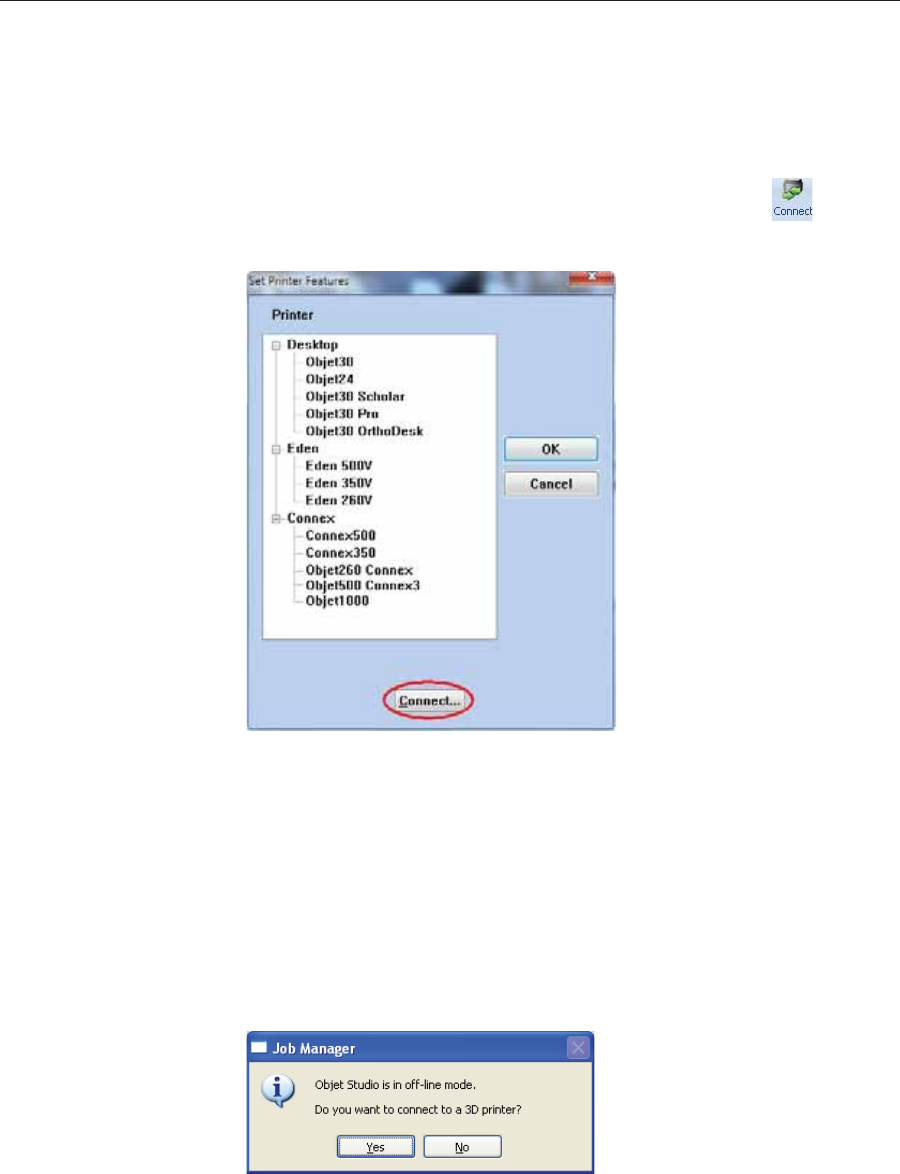
DOC08010 Rev. A (DRAFT 1) 5–71
Stratasys P750K User Guide
Off-line Mode YouȱcanȱuseȱObjetȱStudioȱtoȱprepareȱtraysȱforȱprintingȱinȱoffȬlineȱmode,ȱonȱ
aȱremoteȱcomputerȱorȱwhenȱtheȱprinterȱconnectionȱisȱnotȱavailable.ȱYouȱalsoȱ
useȱoffȬlineȱmodeȱtoȱprepareȱtraysȱforȱprintingȱwithȱotherȱprinters.ȱInȱthisȱ
case,ȱifȱObjetȱStudioȱisȱcurrentlyȱconnectedȱtoȱaȱprinter,ȱyouȱmustȱchangeȱtoȱ
offȬlineȱmodeȱbyȱremovingȱthisȱconnection.
To disconnect Objet Studio from the printer:
1. OnȱtheȱJobȱManagerȱribbon,ȱinȱtheȱ3DȱPrinterȱgroup,ȱclickȱ.
2. InȱtheȱSetȱPrinterȱdialogȱbox,ȱclickȱConnectȱ(seeȱfigure 5Ȭ102).
Figure 5-104: Disconnecting Objet Studio from a printer (A)
3. InȱtheȱPrinterȱConnectionȱdialogȱbox,ȱdeleteȱtheȱcomputerȱname/IPȱ
address.
Figure 5-105: Disconnecting Objet Studio from a printer (B)
4. ClickȱOK.
“Unknown”ȱappearsȱinȱtheȱprinterȬnameȱfield.
5. ClickȱOK.
6. InȱtheȱpopȬupȱmessage,ȱconfirmȱthatȱyouȱwantȱtoȱworkȱinȱoffȬlineȱmodeȱ
byȱclickingȱNo.
Figure 5-106: Off-line message
WhenȱObjetȱStudioȱisȱinȱoffȬlineȱmode,ȱyouȱcanȱconfigureȱitȱforȱpreparingȱ
printȱjobsȱforȱdifferentȱprinters.
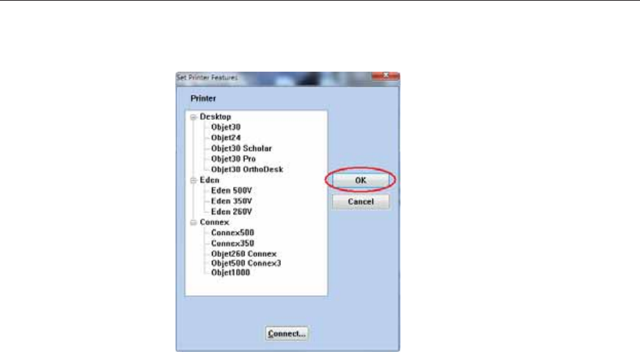
Using Objet Studio
5–72 DOC08010 Rev. A (DRAFT 1)
To change the Objet Studio off-line configuration:
1. InȱtheȱSetȱPrinterȱdialogȱbox,ȱselectȱaȱprinterȱtype.
Figure 5-107: Off-line printer selection
2. ClickȱOKȱ(notȱ“Connect”).
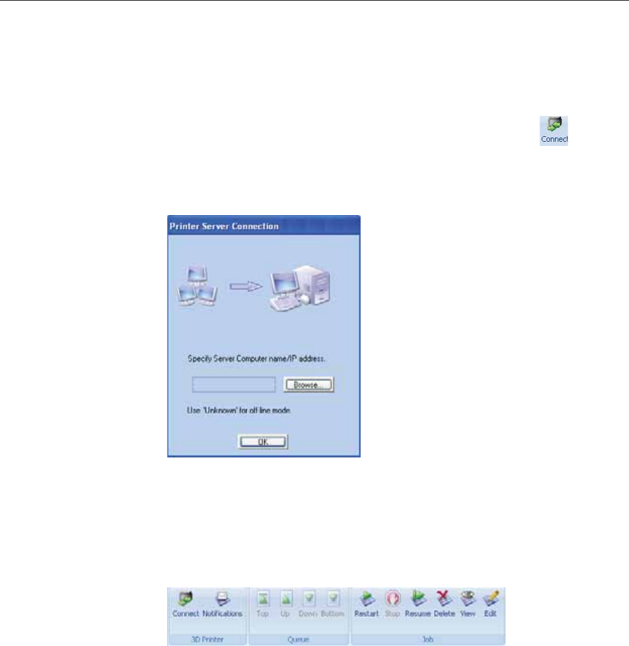
DOC08010 Rev. A (DRAFT 1) 5–73
Stratasys P750K User Guide
Setting the
Remote Printer
Connection
(Client Mode)
WhenȱyouȱopenȱObjetȱStudioȱforȱtheȱfirstȱtimeȱinȱaȱclientȱinstallation,ȱyouȱ
areȱpromptedȱtoȱconnectȱtoȱanȱObjetȱserverȱcomputerȱthatȱsendsȱjobsȱtoȱaȱ3Dȱ
printer.ȱToȱdoȱthis,ȱtheȱserverȱcomputerȱmustȱbeȱoperatingȱandȱconnectedȱtoȱ
theȱlocalȱnetwork.ȱ
To set (or change) the connection to the server-computer:
1. OnȱtheȱJobȱManagerȱribbon,ȱinȱtheȱ3DȱPrinterȱgroup,ȱclickȱ.
2. EnterȱtheȱnameȱofȱtheȱserverȱcomputerȱorȱitsȱIPȱaddress,ȱorȱclickȱBrowseȱ
toȱfindȱandȱselectȱit.
3. ClickȱOK.
Figure 5-108: Printer Server Connection dialog box
Job Manager
Commands TheȱJobȱManagerȱribbonȱhasȱthreeȱiconȱgroups:
•3DȱPrinter
•Queue
•Jobȱ
Figure 5-109: Job Manager ribbon commands
Iconsȱareȱenabledȱorȱdisabledȱaccordingȱtoȱtheirȱrelevancy.ȱForȱexample,ȱ
sinceȱyouȱcannotȱstopȱprintingȱaȱjobȱthatȱisȱnotȱbeingȱprinted,ȱtheȱStopȱ
commandȱisȱdisabledȱwhenȱtheȱprinterȱisȱidle.
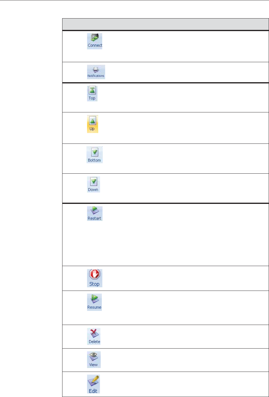
Using Objet Studio
5–74 DOC08010 Rev. A (DRAFT 1)
TheȱfollowingȱoperationsȱareȱavailableȱonȱtheȱJobȱManagerȱribbon:
Group Icon Purpose
3Dȱ
Printer Client:ȱSetsȱtheȱserverȱconnection.ȱSeeȱ“SettingȱtheȱRemoteȱ
PrinterȱConnectionȱ(ClientȱMode)”ȱonȱpage 73.
Server:ȱSetsȱtheȱprinterȱconnection.ȱSeeȱ“SettingȱtheȱPrinterȱ
Connection”ȱonȱpage 70.
Configuresȱoptionsȱforȱprinterȱalerts.ȱSeeȱ“ConfiguringȱUserȱ
Alerts”ȱonȱpage 76.
Queue Server:ȱMovesȱaȱjobȱtoȱtheȱheadȱofȱtheȱJobsȱQueue.
Client:ȱDisabled.
Seeȱ“JobsȱQueue”ȱonȱpage 69.
Server:ȱMovesȱaȱjobȱtoȱaȱhigherȱpositionȱinȱtheȱJobsȱQueue.
Client:ȱDisabled.
Seeȱ“JobsȱQueue”ȱonȱpage 69.
Server:ȱMovesȱaȱjobȱtoȱtheȱbottomȱofȱtheȱJobsȱQueue.ȱ
Client:ȱDisabled.
Seeȱ“JobsȱQueue”ȱonȱpage 69.
Server:ȱMovesȱaȱjobȱtoȱaȱlowerȱpositionȱinȱtheȱJobsȱQueue.
Client:ȱDisabled.
Seeȱ“JobsȱQueue”ȱonȱpage 69.
Job Server:ȱ
•ForȱaȱjobȱinȱtheȱJobsȱQueue—Printsȱitȱagainȱ(fromȱtheȱ
beginning).ȱ
•ForȱaȱjobȱinȱtheȱHistoryȱlist—MovesȱitȱtoȱtheȱJobsȱQueueȱ
forȱprinting.
Client:ȱDisabled.
Seeȱ“RestartingȱJobs”ȱonȱpage 79.
Server:ȱStopsȱaȱjobȱinȱprogress.ȱ
Client:ȱDisabled.
Server:ȱContinuesȱprintingȱtheȱcurrentȱjobȱfromȱtheȱpointȱ
whereȱprintingȱstopped.ȱ
Client:ȱDisabled.
Seeȱ“ResumingȱJobs”ȱonȱpage 79.
Removesȱtheȱselectedȱjobȱfromȱtheȱqueue.ȱ
RefreshesȱtheȱimageȱofȱtheȱselectedȱjobȱinȱtheȱTrayȱPreviewȱ
display.
OpensȱtheȱTrayȱSettingsȱscreenȱandȱdisplaysȱtheȱtray.ȱForȱ
deletedȱjobs,ȱthisȱenablesȱyouȱtoȱmakeȱchangesȱbeforeȱ
printing.
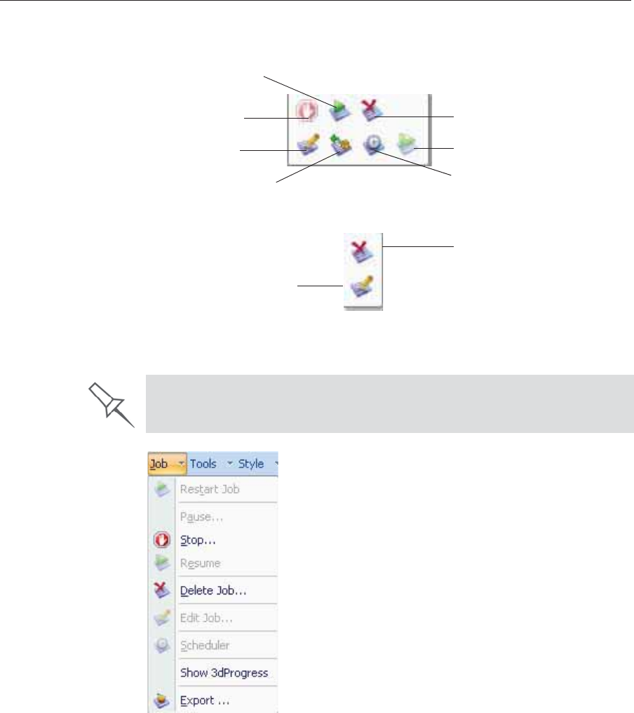
DOC08010 Rev. A (DRAFT 1) 5–75
Stratasys P750K User Guide
Inȱadditionȱtoȱusingȱribbonȱcommandȱicons,ȱyouȱcanȱuseȱcommandsȱonȱ
contextȱ(popȬup)ȱtoolbarsȱandȱfromȱtheȱJobȱmenuȱonȱtheȱstandardȱtoolbar.ȱ
Figure 5-110: Icons on pop-up toolbar (server)
Figure 5-111: Icons on pop-up toolbar (client workstation)
Note: Most icons and menu commands are only enabled when a job is selected.
Figure 5-112: Job menu options (server)
Stop
Edit
Export
packed job Schedule
Resume
Restart
Delete
Edit
Delete
When you position the cursor over an item, a tooltip displays the name of
the command.
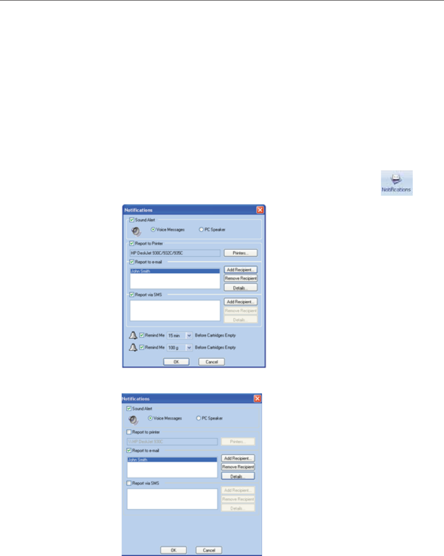
Using Objet Studio
5–76 DOC08010 Rev. A (DRAFT 1)
Configuring
User Alerts ObjetȱStudioȱcanȱalertȱyouȱ(andȱothers)ȱtoȱtheȱstatusȱofȱjobsȱsentȱtoȱtheȱserverȱ
forȱprinting.ȱThisȱisȱespeciallyȱusefulȱduringȱlongȱprintingȱjobs,ȱwhenȱtheȱ
operatorȱisȱawayȱfromȱtheȱprinter.ȱTheȱfollowingȱeventsȱcanȱbeȱreported:
•Theȱlevelȱofȱmodelȱorȱsupportȱmaterialȱisȱlow.
•Theȱjobȱwasȱinterrupted.
•Theȱjobȱwasȱcompletedȱsuccessfully.
ToȱsendȱeȬmailȱandȱSMSȱalerts,ȱmakeȱsureȱthatȱeȬmailȱsoftwareȱsupportingȱ
MAPIȱisȱinstalledȱonȱtheȱserverȱcomputer.ȱToȱsendȱSMSȱalerts,ȱtheȱcellularȱ
phoneȱserviceȱmustȱsupportȱtheȱtransmissionȱofȱeȬmailȱmessagesȱbyȱSMS.ȱ
OnlyȱtheȱsubjectȱlineȱofȱtheȱeȬmailȱmessageȱisȱtransmittedȱbyȱSMS.
To configure Objet Studio to send notifications and alerts:
1. OnȱtheȱJobȱManagerȱribbon,ȱinȱtheȱ3DȱPrinterȱgroup,ȱclickȱ.
Figure 5-113: Notifications dialog box (server)
Figure 5-114: Notifications dialog box (client workstation)
2. Setȱtheȱdesiredȱreportingȱoptions.

DOC08010 Rev. A (DRAFT 1) 5–77
Stratasys P750K User Guide
3. ClickȱDetails.
Figure 5-115: Event selection for alerts
4. InȱtheȱReportsȱEventsȱdialogȱbox,ȱselectȱtheȱalertȱeventsȱandȱclickȱOK.
5. InȱtheȱNotificationsȱdialogȱbox,ȱclickȱOK.
Printing the
Tray IfȱthereȱisȱaȱjobȱinȱtheȱJobsȱQueue,ȱitȱisȱsentȱautomaticallyȱtoȱtheȱStratasysȱ
printer—asȱlongȱasȱitȱisȱon,ȱthereȱisȱaȱconnectionȱtoȱtheȱprinter,ȱandȱtheȱ
printerȱisȱonȱline.ȱChapterȱ6ȱdescribesȱstartingȱandȱoperatingȱtheȱprinter.ȱ
Additional
Server
Features
ObjetȱStudioȱonȱtheȱprinterȱserverȱincludesȱtheȱfollowingȱadditionalȱ
features:
•ExtendedȱTrayȱPreview
•EditingȱJobs
•RestartingȱJobs
•ResumingȱJobs
•SchedulingȱJobs
•ExportingȱJobsȱ(objzf)
•ModifyingȱtheȱJobȱManagerȱScreen
Theseȱfeaturesȱareȱdescribedȱonȱtheȱfollowingȱpages.
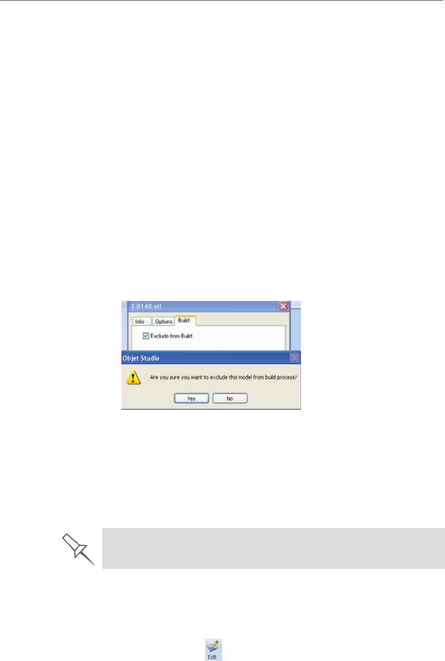
Using Objet Studio
5–78 DOC08010 Rev. A (DRAFT 1)
ExtendedȱTrayȱPreview
Inȱthisȱwindow,ȱyouȱcanȱviewȱtheȱtrayȱfromȱdifferentȱanglesȱandȱ
magnificationsȱwithoutȱleavingȱtheȱJobȱManagerȱscreen.ȱInȱadditionȱtoȱ
displayingȱtheȱselectedȱjobȱinȱtheȱTrayȱPreviewȱpane,ȱyouȱcanȱopenȱanȱ
enlargedȱbuildȱtrayȱwindow.
To display the build tray window:
1. SelectȱaȱjobȱinȱtheȱJobsȱQueueȱorȱtheȱHistoryȱlist.
2. ClickȱtheȱTrayȱPreviewȱpane.
Figure 5-116: Job Preview
•Toȱchangeȱtheȱtrayȱmagnification,ȱturnȱtheȱmouseȱwheel.ȱ
•Toȱviewȱtheȱtrayȱfromȱaȱdifferentȱperspective,ȱclickȱtheȱrelevantȱicon.
•Toȱresizeȱtheȱwindow,ȱdragȱitsȱedgeȱorȱcorners.
Ifȱthereȱareȱseveralȱobjectsȱonȱtheȱbuildȱtray,ȱyouȱcanȱexcludeȱoneȱorȱmoreȱ
fromȱbeingȱprinted,ȱwithoutȱactuallyȱdeletingȱtheȱobjectȱfromȱtheȱtrayȱfile.
To prevent the printing of an object on the build tray:
1. DoubleȬclickȱonȱtheȱobjectȱyouȱdoȱnotȱwantȱtoȱprint.
2. DisplayȱtheȱBuildȱtab.
3. SelectȱExclude from Build.
Figure 5-117: Excluding a model from the build
4. ClickȱYesȱtoȱconfirm.
Onȱserverȱcomputers,ȱyouȱcanȱuseȱTrayȱPreviewȱtoȱdynamicallyȱdisplayȱ
objectsȱasȱtheyȱareȱprinted,ȱlayerȱbyȱlayer.ȱThisȱenablesȱyouȱtoȱvisuallyȱ
monitorȱprintingȱprogressȱonȱtheȱcomputerȱscreen.
To display printing progress in the Tray Preview pane:
¾FromȱtheȱJobȱmenu,ȱselectȱShow 3dProgress.
EditingȱJobs
YouȱcanȱopenȱjobsȱinȱtheȱJobsȱQueueȱforȱediting.
To edit a job:
1. Selectȱtheȱjob.
2. ClickȱtheȱEditȱiconȱ.
This option uses additional system resources.
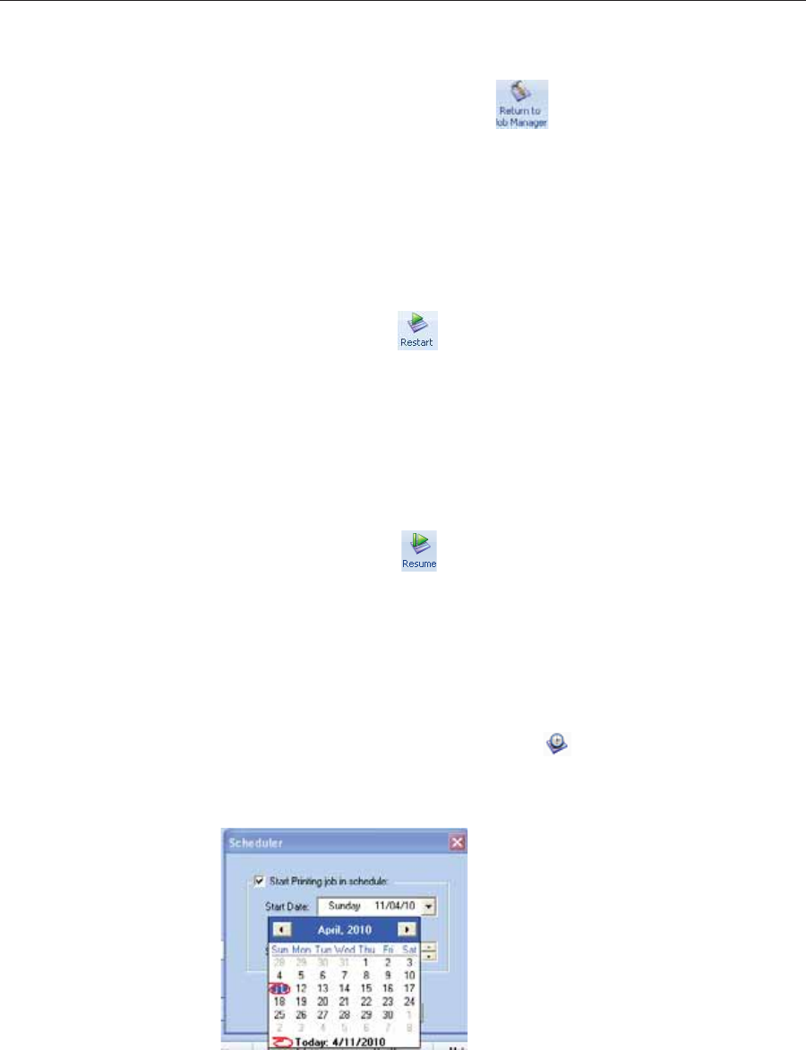
DOC08010 Rev. A (DRAFT 1) 5–79
Stratasys P750K User Guide
TheȱTrayȱSettingsȱscreenȱopens,ȱdisplayingȱtheȱbuildȱtray.ȱTheȱstatusȱofȱ
theȱjobȱinȱtheȱJobȱManagerȱscreenȱchangesȱtoȱ“Editing.”
3. Editȱtheȱjob.ȱ
4. OnȱtheȱTrayȱSettingsȱribbon,ȱclickȱ.
TheȱstatusȱofȱtheȱjobȱinȱtheȱJobȱManagerȱscreenȱchangesȱbackȱtoȱ
“Waiting.”
RestartingȱJobsȱ
YouȱcanȱrestartȱjobsȱfromȱtheȱJobsȱQueueȱandȱtheȱHistoryȱlist.
To restart a job:
1. Selectȱtheȱjob.
2. ClickȱtheȱRestartȱiconȱ.
Theȱjobȱstatusȱchangesȱtoȱ“Waiting”ȱ(inȱtheȱJobsȱQueue).
ResumingȱJobsȱ
Ifȱtheȱprintingȱprocessȱisȱstoppedȱorȱinterrupted,ȱyouȱmayȱbeȱableȱtoȱ
continueȱprintingȱtheȱjobȱfromȱtheȱpointȱwhereȱprintingȱstopped.
To resume a job:
1. Selectȱtheȱjob.
2. ClickȱtheȱResumeȱiconȱ.
SchedulingȱJobs
Youȱcanȱscheduleȱjobsȱtoȱbeȱprintedȱatȱaȱfutureȱtime.ȱForȱexample,ȱyouȱcanȱ
configureȱObjetȱStudioȱtoȱstartȱlongȱprintingȱjobsȱinȱtheȱlateȱeveningȱandȱ
earlyȱmorningȱhours.
To schedule a job:
1. SelectȱaȱjobȱinȱtheȱJobsȱQueue,ȱandȱclickȱȱonȱtheȱpopȬupȱtoolbar.
2. InȱtheȱSchedulerȱdialogȱbox,ȱsetȱtheȱStartȱDateȱandȱStartȱTimeȱforȱtheȱjob.ȱ
ClickȱonȱtheȱStartȱDateȱarrowȱtoȱopenȱaȱcalendar.
Figure 5-118: Scheduler with calendar displayed
3. ClickȱOK.

Using Objet Studio
5–80 DOC08010 Rev. A (DRAFT 1)
ExportingȱJobsȱ(objzf)
Youȱcanȱsaveȱprintȱjobsȱasȱcompressedȱfiles.
Toȱexportȱaȱprintȱjob:
1. Selectȱaȱjob.
2. OnȱtheȱpopȬupȱtoolbar,ȱclickȱ.
3. InȱtheȱSaveȱAsȱdialogȱbox,ȱselectȱaȱfolder.
4. ClickȱSave.
ModifyingȱtheȱJobȱManagerȱScreen
YouȱcanȱchangeȱtheȱsizeȱofȱtheȱsectionsȱofȱtheȱJobȱManagerȱscreen,ȱbyȱ
draggingȱtheȱpanelȱedges.ȱThisȱappliesȱto:
•theȱJobsȱQueueȱpanel
•theȱTimeȱpanel
•theȱHistoryȱpanel
Similarly,ȱyouȱcanȱchangeȱtheȱwayȱtheȱscreenȱareaȱisȱdividedȱbetweenȱtheȱ
mainȱsectionȱ(JobsȱQueue/Time/History)ȱandȱtheȱpanelsȱonȱtheȱrightȱsideȱofȱ
theȱscreen.
Youȱcanȱcollapseȱ(hide)ȱtheȱrightȱpanelsȱ(AvailableȱResources/Materialȱ
Consumption/TrayȱView)ȱbyȱclickingȱtheȱtopȱofȱtheȱpanel.
•Clickȱagainȱtoȱdisplayȱtheȱpanel.
For an explanation of objzf files, see “Exporting and Importing Objet Build
Trays” on page 56.

DOC08010 Rev. A (DRAFT 1) 6–1
Operating & Maintaining the
Stratasys P750K
3D
Printer
StartingȱtheȱPrinter.............................................................................. 2
LoadingȱModelȱandȱSupportȱCartridges.......................................... 4
ProducingȱModels............................................................................... 5
PreparingȱtheȱPrinter............................................................................5
PrinterȱInterfaceȱColor Key..................................................................7
PrintingȱIndicators................................................................................8
ResumingȱProductionȱAfterȱPrintingȱhasȱStopped......................... 9
ChangingȱtheȱPrintingȱMaterial ...................................................... 11
KeepingȱtheȱPrinterȱinȱIdleȱMode ................................................... 16
ShuttingȱDownȱtheȱPrinter............................................................... 17
MaintainingȱtheȱPrinter.................................................................... 19
RoutineȱMaintenanceȱSchedule.........................................................19
UVȱLampȱCheck..................................................................................20
CleaningȱtheȱPrintȱHeadsȱandȱtheȱRoller.........................................20
CleaningȱandȱReplacingȱtheȱWiper...................................................23
PatternȱTest...........................................................................................25
ImprovingȱPrintȱQuality ....................................................................26
CleaningȱtheȱRollerȱWasteȱCollectorȱandȱInspectingȱtheȱRollerȱ
Scraper..................................................................................................27
ReplacingȱtheȱRollerȱScraper .............................................................30
AligningȱtheȱPrintȱHeads...................................................................32
Optimizingȱ(Calibrating)ȱPrintȱHeads .............................................35
ReplacingȱPrint Heads........................................................................42
TestingȱandȱCalibratingȱtheȱUVȱLamps ...........................................53
CalibratingȱtheȱLoadȱCells.................................................................59
ReplacingȱtheȱOdorȱFilter...................................................................61
ReplacingȱtheȱUVȱLamps ...................................................................61
BuiltȬinȱTests.........................................................................................66
ReplacingȱtheȱWasteȱContainer.........................................................71
CleaningȱtheȱExteriorȱPanels .............................................................73
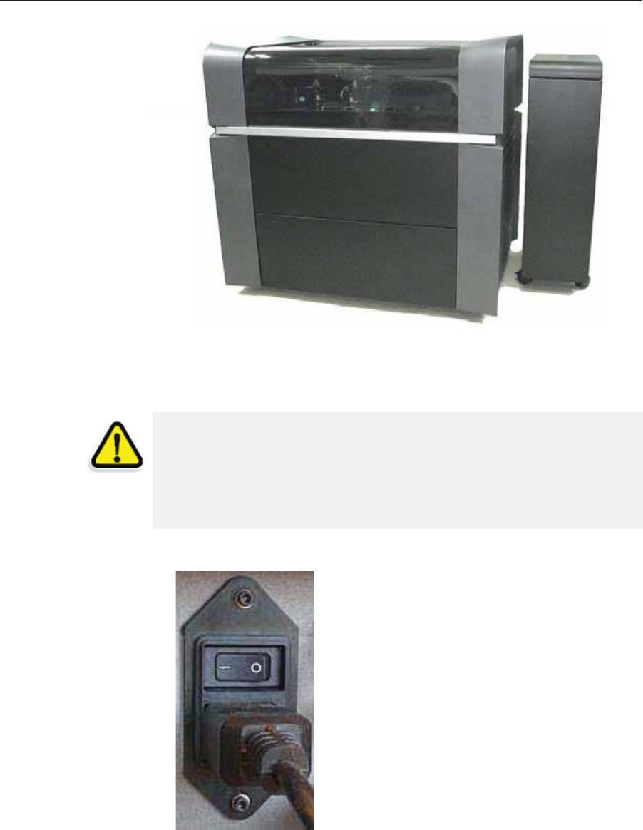
Operating & Maintaining the Stratasys P750K 3D Printer
6–2 DOC08010 Rev. A (DRAFT 1)
Figure 6-1: The Stratasys P750K 3D Printer
Starting the Printer
1. Turnȱonȱtheȱmainȱpowerȱswitch,ȱlocatedȱatȱtheȱbackȱofȱtheȱprinter.
Figure 6-2: Main power switch and cable
Printer cover
Materials cabinet
CAUTION!
¾Do not attempt to operate the Stratasys printer before being trained by a
Stratasys customer-support representative.
¾Observe all safety warnings and follow the safety guidelines described
in chapter 2.
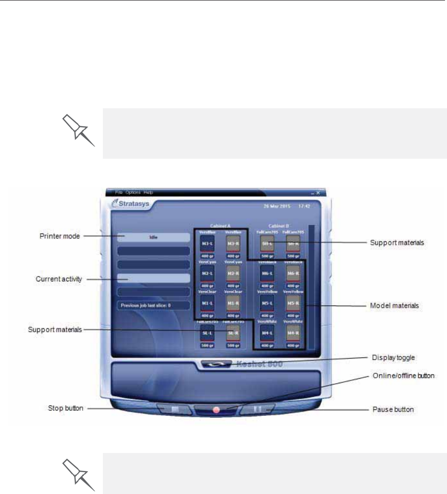
DOC08010 Rev. A (DRAFT 1) 6–3
Stratasys P750K User Guide
2. AfterȱtheȱprinterȬcontrolȱcomputerȱboots,ȱlogȱinȱtoȱWindowsȱandȱ
launchȱtheȱprinterȬcontrolȱprogram:
•OnȱtheȱprinterȬcomputerȱdesktop,ȱdoubleȬclickȱtheȱStratasysȱprinterȱ
icon.
or—
•FromȱtheȱStartȱmenu,ȱselectȱ(All) Programs > Objet >Stratasys P750K.
Allȱmonitoringȱandȱcontrollingȱofȱtheȱprinterȱisȱdoneȱfromȱthisȱinterface.
Figure 6-3: Stratasys P750K interface
A HASP plug containing a valid product activation key is required on the
printer computer. This is installed at the factory or during printer upgrade. If
the application does not open and a HASP message appears, contact your
dealer or Stratasys Customer Support.
One monitor displays both the computer running Objet Studio and the
printer server computer. Make sure that the printer interface is displayed.

Operating & Maintaining the Stratasys P750K 3D Printer
6–4 DOC08010 Rev. A (DRAFT 1)
Loading Model and Support Cartridges
StratasysȱP750Kȱprintersȱuseȱupȱtoȱ12ȱcartridgesȱofȱModelȱmaterialȱandȱfourȱ
cartridgesȱofȱSupportȱmaterial,ȱeachȱweighingȱ3.6ȱkilogramsȱwhenȱfull.ȱAȱ
graphicalȱrepresentationȱofȱtheȱcartridgesȱloadedȱandȱtheirȱcurrentȱweightȱ
appearsȱinȱtheȱprinterȱinterfaceȱ(seeȱfigure 6Ȭ3).
Important:ȱȱIfȱyouȱneedȱtoȱreplaceȱtheȱModelȱmaterialȱcurrentlyȱ
installedȱwithȱanotherȱtype,ȱseeȱ“ChangingȱtheȱPrintingȱMaterial”ȱ
onȱpage 11.ȱOtherwise,ȱmakeȱsureȱtoȱreplaceȱtheȱModelȱcartridgeȱ
withȱoneȱcontainingȱtheȱsameȱtypeȱofȱmaterial.
To load Model and Support material:
1. Openȱtheȱdoorsȱofȱtheȱmaterialsȱcabinet.
2. LoadȱModelȱandȱSupportȱcontainersȱintoȱtheirȱrespectiveȱ
compartments.
Youȱshouldȱfeelȱsomeȱresistance,ȱasȱaȱneedleȱpiercesȱtheȱcartridge.ȱ
3. Checkȱtheȱprinterȱinterfaceȱtoȱmakeȱsureȱthatȱtheȱnewȱcartridgeȱisȱ
detectedȱandȱthatȱitsȱweightȱisȱdisplayedȱ(seeȱfigure 6Ȭ3).
4. Closeȱtheȱmaterialsȱcabinet.
The materials cabinet uses RFID technology to automatically identify
cartridges of printing material. For this purpose, an RFID module is built into
the cabinet. Tampering with this module will render the printer inoperable
and may void Stratasys warranties and service contracts.
Tips about loading and replacing material cartridges:
¾You can load partially used cartridges, as long as they contain more than
100 grams of material.
¾You can replace material cartridges either before or during printing.
¾If printing stops for an extended time before you replace a material
cartridge, the printer may go into Standby or Idle mode. If this happens,
see “Resuming Production After Printing has Stopped” on page 9.
¾You can replace partially used cartridges to avoid the need for replacing
them during printing.
¾The cartridge type is automatically detected by the printer. If you replace
a cartridge containing different Model material, a message appears
recommending that you run the Material Replacement wizard to flush out
the old material.
DOC08010 Rev. A (DRAFT 1) 6–5
Stratasys P750K User Guide
Producing Models
TheȱStratasysȱP750Kȱprinterȱproducesȱmodelsȱbyȱprintingȱtrayȱfilesȱ
preparedȱinȱtheȱObjetȱStudioȱapplicationȱandȱsentȱtoȱtheȱprinterȱfromȱthere.ȱ
Forȱinformationȱaboutȱpreparingȱmodelȱfilesȱforȱprinting,ȱseeȱ“UsingȱObjetȱ
Studio”ȱinȱthisȱuserȱguideȱorȱObjetȱStudioȱHelp.
Preparing the
Printer
To prepare the printer for producing models:
1. Makeȱsureȱthatȱtheȱbuildȱtrayȱinȱtheȱprinterȱisȱemptyȱandȱclean.ȱIfȱnot,ȱ
removeȱcuredȱmaterialȱwithȱtheȱscraper,ȱandȱcleanȱtheȱtrayȱthoroughlyȱ
withȱaȱwetȱcleaningȱcloth.
2. MakeȱsureȱthatȱthereȱisȱsufficientȱModelȱandȱSupportȱmaterialȱloaded,ȱ
asȱindicatedȱinȱtheȱprinterȱinterfaceȱ(seeȱfigure 6Ȭ3).ȱYouȱmayȱwantȱtoȱ
replaceȱtheȱcartridgesȱofȱModelȱandȱSupportȱmaterialȱcurrentlyȱloadedȱ
inȱtheȱprinterȱtoȱavoidȱtheȱneedȱforȱreplacingȱthemȱduringȱprinting.ȱ
Before beginning to produce models, it is recommended that you check the
current printing quality of the print heads by performing a pattern test (see
“Pattern Test” on page 25).
CAUTION: Use protective gloves when cleaning the build tray, and be
careful of the sharp edges of the scraper blade.
Forȱinstallingȱmaterialȱcartridgesȱandȱreplacingȱemptyȱones,ȱseeȱ
“LoadingȱModelȱandȱSupportȱCartridges”ȱonȱpage 4.
ForȱchangingȱtheȱtypeȱofȱModelȱmaterialȱcurrentlyȱloaded,ȱseeȱ
“ChangingȱtheȱPrintingȱMaterial”ȱonȱpage 11.
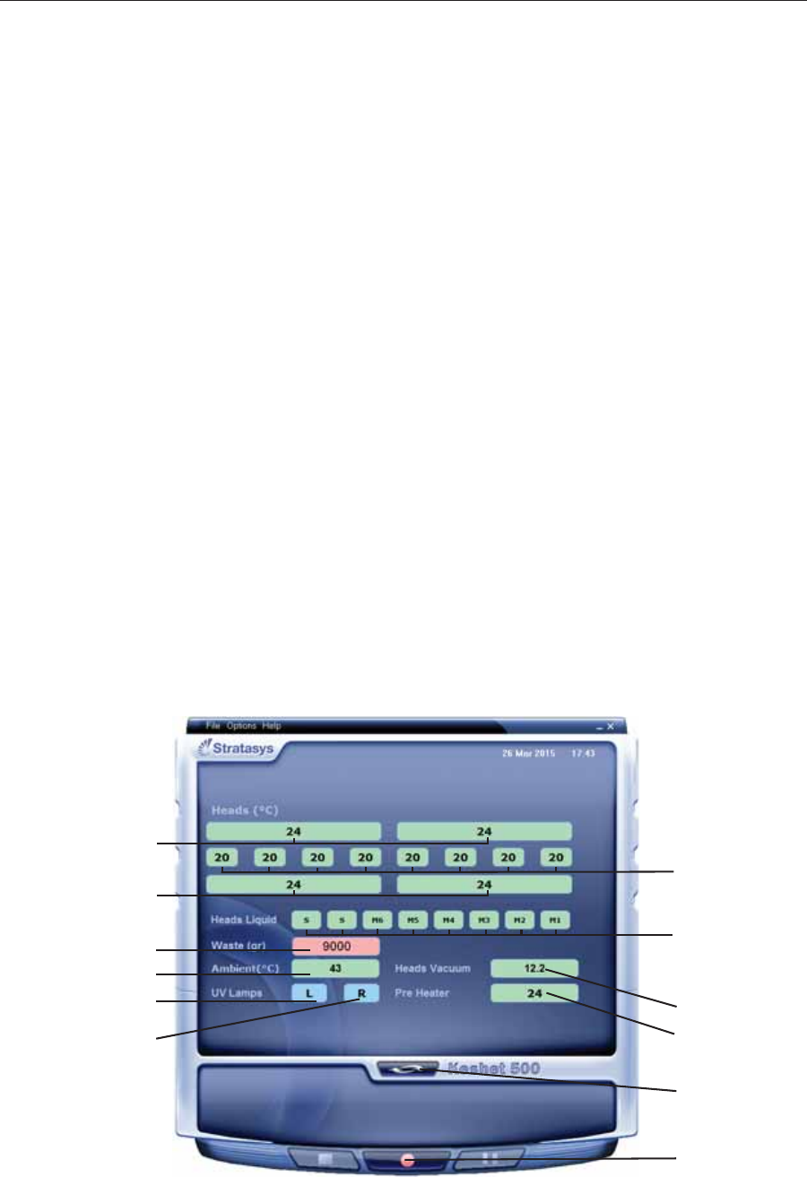
Operating & Maintaining the Stratasys P750K 3D Printer
6–6 DOC08010 Rev. A (DRAFT 1)
3. cartridgesOnȱtheȱprinterȱinterface,ȱclickȱtheȱredȱbuttonȱtoȱswitchȱtheȱ
printerȱtoȱonlineȱmode.
Theȱcolorȱofȱtheȱbuttonȱchangesȱfromȱredȱtoȱgreenȱ(seeȱfigure 6Ȭ4).ȱIfȱ
thereȱisȱaȱjobȱinȱtheȱJobȱManagerȱqueue,ȱitȱisȱsentȱtoȱtheȱprinter.ȱ
Inȱtheȱprinterȱinterface,ȱtheȱprinterȱmodeȱchangesȱfromȱIdleȱtoȱPreȬprint,ȱasȱ
theȱprinter’sȱcomponentsȱprepareȱthemselvesȱforȱproduction:ȱ
•Theȱprintȱblockȱisȱheated.
•TheȱUVȱlampsȱareȱpoweredȱandȱtheyȱwarmȱup.
Whenȱprintingȱbegins,ȱObjetȱStudioȱsendsȱsevenȱslicesȱtoȱtheȱprinterȬcontrolȱ
application.ȱThisȱisȱtheȱstandardȱbufferȱbetweenȱObjetȱStudioȱandȱtheȱ
printer.ȱAsȱeachȱsliceȱisȱprinted,ȱanotherȱsliceȱisȱsentȱtoȱtheȱprinter.
Dependingȱonȱtheȱsizeȱofȱtheȱmodel(s)ȱtoȱbeȱproduced,ȱprintingȱcanȱtakeȱ
betweenȱseveralȱhoursȱtoȱseveralȱdays.ȱAsȱlongȱasȱthereȱisȱenoughȱModelȱ
andȱSupportȱmaterialȱinȱtheȱsupplyȱcartridges,ȱprintingȱproceedsȱ
automaticallyȱuntilȱtheȱjobȱisȱfinished.
TheȱStratasysȱP750KȱprinterȱusesȱupȱtoȱsixȱdifferentȱModelȬmaterialȱ
cartridgesȱtoȱproduceȱmodels.ȱInȱaddition,ȱtwoȱSupportȬmaterialȱcartridgesȱ
areȱrequired.ȱIfȱadditionalȱcartridgesȱareȱinstalledȱandȱtheyȱareȱnotȱneededȱ
forȱtheȱcurrentȱprintȱjob,ȱtheȱprinterȱinterfaceȱindicatesȱwhichȱareȱbeingȱ
used:
•Blueȱcartridge—usedȱforȱtheȱprintȱjob
•Grayȱcartridge—notȱusedȱforȱtheȱprintȱjob
Youȱcanȱmonitorȱprinterȱstatusȱindicatorsȱbyȱswitchingȱtheȱprinterȱinterfaceȱ
display.ȱToȱdoȱthis,ȱclickȱtheȱdisplayȱtoggleȱbuttonȱinȱtheȱprinterȱinterfaceȱ
screen.
Figure 6-4: Printer indicators
Temperature.
in front of
print block
Temperature
behind
print block
Waste weight
Display
toggle button
Printer set to
online mode
(green)
Chamber temp.
Left UV lamp
Right UV lamp
Temp. of each head
Support/Model
material in print-
block reservoir
System
vacuum level
Temp. of material
pre-heaters

DOC08010 Rev. A (DRAFT 1) 6–7
Stratasys P750K User Guide
Printer
Interface
Color Key
Theȱbackgroundȱcolorsȱinȱtheȱprinterȱindicatorȱfieldsȱtellȱyouȱatȱaȱglanceȱ
whetherȱorȱnotȱtheȱvalueȱorȱitemȱisȱsuitableȱorȱreadyȱforȱprinting.ȱ
•Green—suitable/readyȱforȱprinting
Forȱexample,ȱinȱfigure 6Ȭ4:
Headsȱ(°C)—Theȱheadsȱhaveȱreachedȱtheȱtemperatureȱrequiredȱforȱ
printingȱmodels.
Ambient—Theȱambientȱtemperatureȱofȱtheȱprintingȱchamberȱisȱ
withinȱtheȱacceptableȱrange.
HeadsȱLiquid—TheȱlevelȱofȱModelȱandȱSupportȱmaterialȱinȱtheȱ
printȬblockȱreservoirȱisȱOK.
Vacuum—Theȱvacuumȱlevelȱinȱtheȱsystemȱisȱwithinȱtheȱacceptableȱ
range.
•Red—notȱsuitableȱforȱprintingȱ(orȱindicatesȱaȱwarning)
Forȱexample,ȱinȱfigure 6Ȭ4:ȱ
Waste—Theȱweightȱofȱtheȱwasteȱcontainerȱisȱ9000ȱgrams,ȱmoreȱthanȱ
allowedȱwhenȱbeginningȱaȱprintȱjob.ȱ(Seeȱ“ReplacingȱtheȱWasteȱ
Container”ȱonȱpage 71.)
•Blue—notȱready
Forȱexample,ȱinȱfigure 6Ȭ4:
UVȱlamps—TheȱUVȱlampsȱareȱnotȱon.
Theȱcolorȱofȱtheȱmaterialȱcartridgesȱdisplayedȱinȱtheȱprinterȱinterfaceȱ
indicatesȱwhichȱcartridgesȱareȱactiveȱforȱtheȱcurrentȱ(orȱnext)ȱprintȱjob.
•Blue—activeȱcartridges
•Gray—reserveȱcartridges
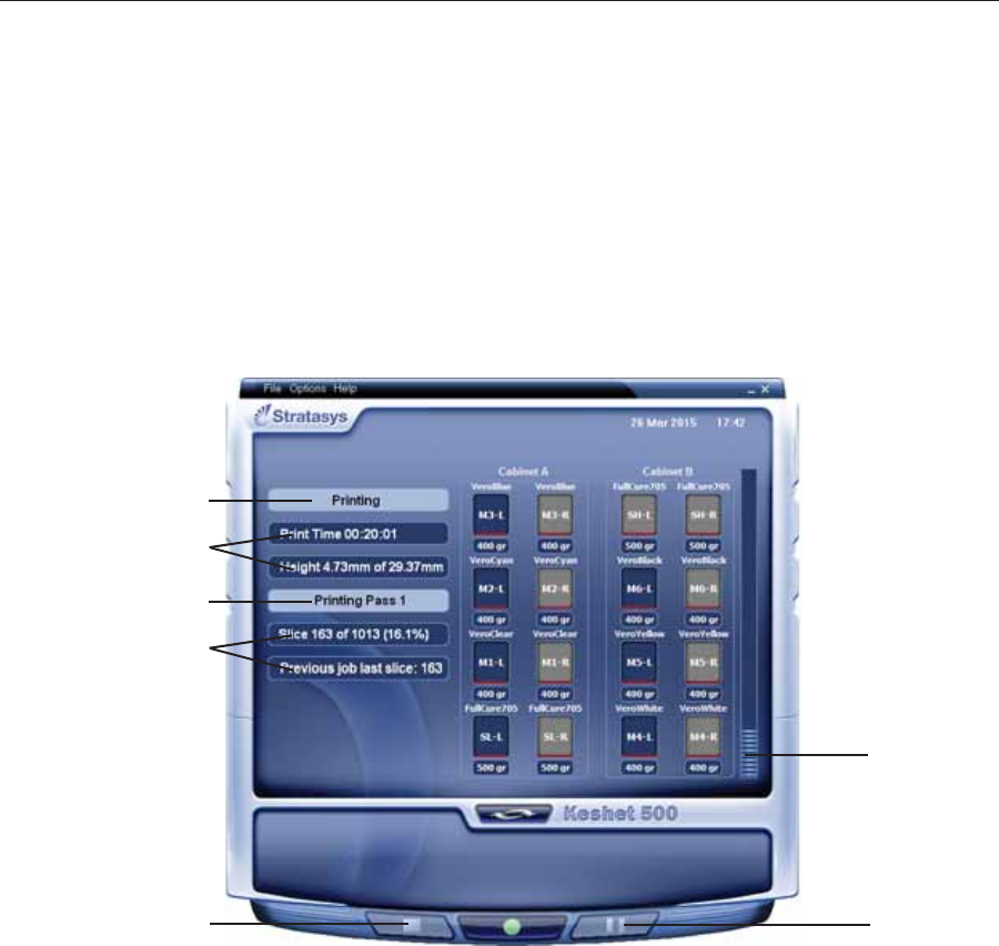
Operating & Maintaining the Stratasys P750K 3D Printer
6–8 DOC08010 Rev. A (DRAFT 1)
Printing
Indicators TheȱprinterȱinterfaceȱscreenȱchangesȱwhenȱyouȱsendȱaȱprintȱjobȱfromȱObjetȱ
Studioȱtoȱtheȱprinter,ȱandȱtheȱprinterȱisȱonȱlineȱ(seeȱfigure 6Ȭ5):
•TheȱmodeȱchangesȱfromȱPreȬprintȱtoȱPrinting.ȱ
•Theȱspecificȱactivityȱbeingȱperformedȱisȱshownȱinȱtheȱ“currentȱactivity”ȱ
field.ȱ
•CurrentȱjobȬprintingȱinformationȱisȱdisplayed.
•Theȱprintingȱprogressȱbarȱisȱdisplayed.
•TheȱStopȱandȱPauseȱbuttonsȱareȱenabled.
Whenȱtheȱweightȱofȱaȱcartridgeȱdropsȱbelowȱ100ȱgrams,ȱtheȱdisplayȱofȱtheȱ
materialȱlevelȱinȱtheȱprinterȱinterfaceȱisȱred.ȱ
Figure 6-5: Printer interface during printing
Progress bar
Pause button
Stop button
Printer mode
Job information
Job information
Current activity
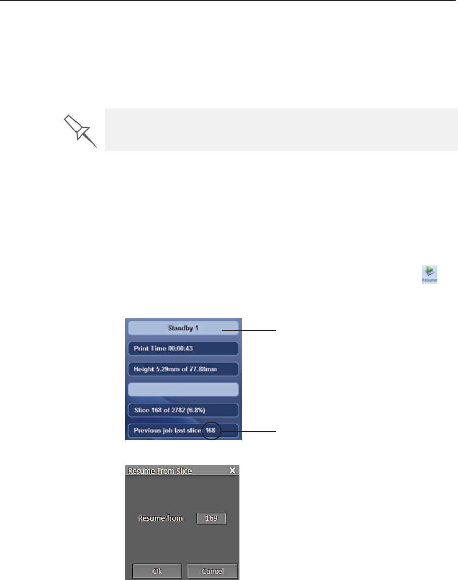
DOC08010 Rev. A (DRAFT 1) 6–9
Stratasys P750K User Guide
Resuming Production After Printing has Stopped
Ifȱtheȱprintingȱprocessȱisȱinterrupted,ȱObjetȱStudioȱstopsȱsendingȱslicesȱtoȱ
theȱprinter.ȱThisȱcanȱhappen,ȱforȱexample,ȱifȱtheȱprintingȱmaterialȱrunsȱoutȱ
inȱtheȱmiddleȱofȱaȱprintȱjob,ȱandȱyouȱdon’tȱreplaceȱtheȱemptyȱcartridgeȱ
immediately.ȱAfterȱtheȱprinterȱchangesȱtoȱStandbyȱorȱIdleȱmode,ȱyouȱneedȱtoȱ
resumeȱprintingȱfromȱtheȱJobȱManagerȱscreenȱofȱObjetȱStudio.
To continue printing the model:
1. Ifȱtheȱprinterȱisȱinȱofflineȱmode,ȱswitchȱitȱtoȱonlineȱmodeȱbyȱclickingȱtheȱ
redȱbuttonȱatȱtheȱbottomȱofȱtheȱprinterȱinterfaceȱ(seeȱfigure 6Ȭ3ȱonȱ
page 3).
Theȱbuttonȱchangesȱfromȱredȱtoȱgreenȱ(seeȱfigure 6Ȭ4ȱonȱpage 6).
2. Ifȱyouȱdon’tȱknowȱwhyȱprintingȱhasȱstopped,ȱmakeȱsureȱthatȱtheȱ
connectionȱbetweenȱtheȱprinterȱandȱtheȱserverȱcomputerȱisȱactive.
3. InȱtheȱJobȱManagerȱscreenȱofȱObjetȱStudio,ȱclickȱtheȱResumeȱiconȱ.
4. InȱtheȱContinueȱfromȱSliceȱdialogȱboxȱthatȱappears,ȱconfirmȱtheȱsliceȱ
number,ȱafterȱcheckingȱtheȱprinterȱinterface.
Figure 6-6: Printer interface after interrupted printing
Figure 6-7: Continue from Slice confirmation in Objet Studio (Job Manager
screen)
5. If,ȱforȱanyȱreason,ȱtheȱcorrectȱnumberȱdoesȱnotȱappearȱinȱtheȱdialogȱ
box,ȱenterȱtheȱnumberȱandȱclickȱOK.
After printing stops, the printer goes into Standby mode, when heating of
print heads is reduced. About 10 hours later, the printer goes into Idle mode,
when heating of print heads is stopped.
Printer mode
Last slice printed

Operating & Maintaining the Stratasys P750K 3D Printer
6–10 DOC08010 Rev. A (DRAFT 1)
Youȱcannotȱcontinueȱprintingȱtheȱmodelȱif:
•Theȱnumberȱofȱtheȱlastȱsliceȱprintedȱdoesȱnotȱappearȱinȱtheȱprinterȱ
interface,ȱevenȱifȱtheȱserverȱcomputerȱdisplaysȱtheȱContinueȱfromȱSliceȱ
confirmationȱdialogȱbox.
•Thereȱwasȱaȱrelativelyȱlongȱinterruptionȱinȱprinting,ȱevenȱifȱtheȱ“lastȱ
slice”ȱandȱ“continueȱfromȱslice”ȱindicatorsȱareȱcorrect.ȱTheȱpartȱofȱtheȱ
modelȱalreadyȱprintedȱmayȱdeformȱorȱshrink,ȱandȱthereȱmightȱbeȱaȱ
visibleȱdifferenceȱbetweenȱitȱandȱtheȱnewlyȱprintedȱpart.ȱTheȱeffectsȱofȱaȱ
printingȱstoppageȱonȱaȱmodelȱdependȱonȱtheȱmodelȱsizeȱandȱstructure,ȱ
Modelȱmaterialȱused,ȱambientȱtemperatureȱandȱtheȱlengthȱofȱtheȱ
stoppage.
If you cannot continue printing:
1. CancelȱtheȱprintȱjobȱinȱtheȱJobȱManagerȱscreen.
2. Removeȱtheȱpartiallyȱprintedȱmodelȱfromȱtheȱbuildȱtray.ȱ
3. RestartȱtheȱjobȱfromȱtheȱJobȱManagerȱscreenȱ(inȱObjetȱStudio).
You can stop and later resume printing from either the printer interface or
from the Job Manager screen of Objet Studio. After clicking the Stop button
on the printer interface, you can resume printing only from the Job Manager
screen. However, after clicking the Pause button in the printer interface, you
can only resume printing from the printer interface.
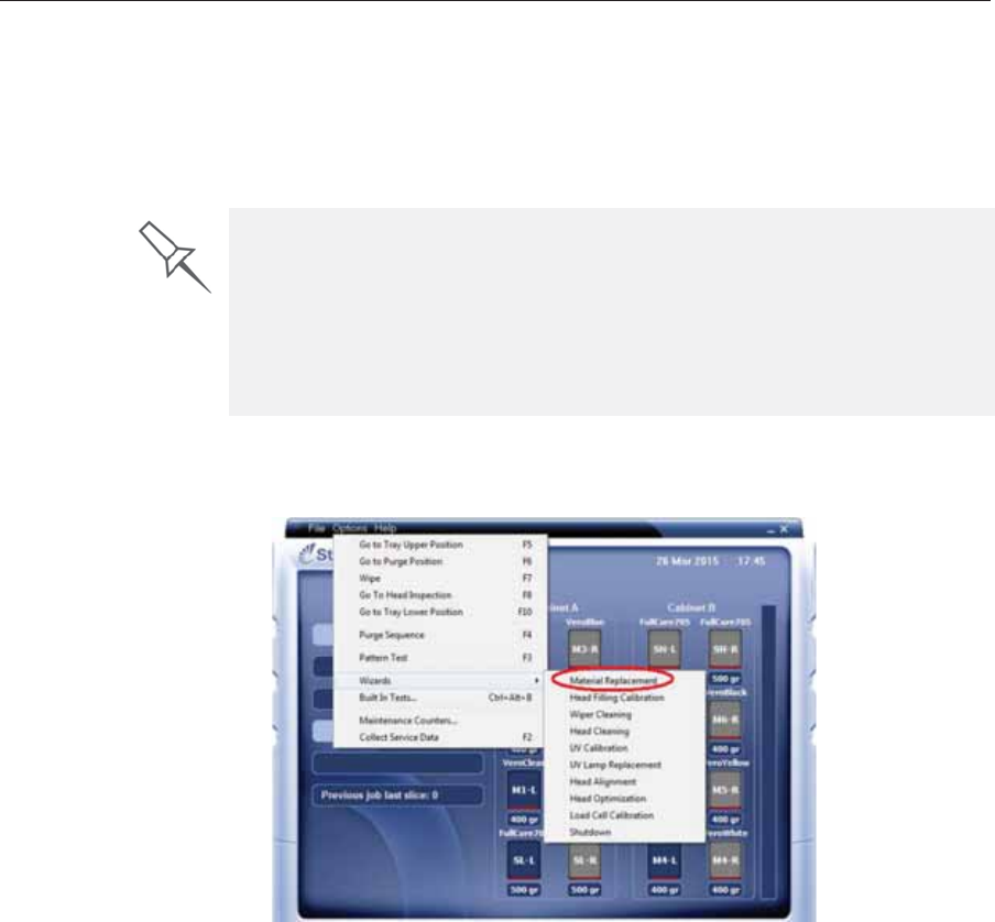
DOC08010 Rev. A (DRAFT 1) 6–11
Stratasys P750K User Guide
Changing the Printing Material
Beforeȱproducingȱmodelsȱusingȱaȱdifferentȱtypeȱofȱprintingȱmaterialȱthanȱisȱ
currentlyȱinstalled,ȱrunȱtheȱMaterialȱReplacementȱwizardȱtoȱflushȱtheȱprintȱ
blockȱandȱfeedȱtubes.
To replace the printing material with the wizard:
1. StartȱtheȱMaterialȱReplacementȱwizardȱfromȱtheȱOptionsȱmenu.
Figure 6-8: Starting the Material Replacement wizard
2. Inȱtheȱopeningȱscreen,ȱclickȱNext.
You should carefully plan printing models with different Model materials to
avoid unnecessary waste of the materials currently loaded. The amount of
material flushed depends on the flushing cycle chosen and if you are
replacing one or more Model cartridges.
The Material Replacement wizard suggests the best slot locations for
placing different material cartridges, based on materials currently in the
system. This ensures minimum flushing of materials currently loaded.
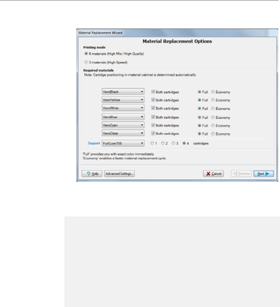
Operating & Maintaining the Stratasys P750K 3D Printer
6–12 DOC08010 Rev. A (DRAFT 1)
3. Ifȱtheȱprinterȱcoverȱisȱnotȱclosed,ȱaȱscreenȱappears,ȱpromptingȱyouȱtoȱ
closeȱtheȱcover.ȱConfirmȱthatȱitȱisȱclosedȱandȱclickȱNext.
4. Chooseȱtheȱconfigurationȱforȱproducingȱmodels:ȱ
•6ȱmaterials
•3ȱmaterials
5. InȱtheȱRequiredȱmaterialsȱsectionȱofȱtheȱwizardȱscreen,ȱselectȱoneȱorȱmoreȱ
replacementȱmaterials.
6. SelectȱBoth cartridgesȱifȱyouȱneedȱtoȱloadȱtwoȱreplacementȱcartridges.
Loadingȱoneȱreplacementȱcartridgeȱisȱmoreȱeconomicalȱbecauseȱitȱ
potentiallyȱrequiresȱlessȱflushingȱofȱmaterialȱcurrentlyȱinȱtheȱsystem.ȱ
However,ȱwhenȱoneȱcartridgeȱisȱnotȱsufficient,ȱloadingȱtwoȱcartridgesȱ
enablesȱcontinuousȱprintingȱuntilȱtheȱprintȱjobȱisȱcompleted.ȱWhenȱoneȱ
cartridgeȱemptiesȱandȱtheȱotherȱoneȱisȱbeingȱused,ȱyouȱcanȱreplaceȱtheȱ
emptyȱcartridgeȱwithȱaȱnewȱone.
¾6 materials
EachȱofȱtheȱModelȱmaterialsȱisȱloadedȱintoȱaȱseparateȱchamberȱinȱtheȱ
printȱheads.
Youȱcanȱprintȱwithȱanyȱofȱtheȱloadedȱmaterialsȱwithoutȱtheȱneedȱtoȱ
runȱtheȱwizard.
¾3 materials
TwoȱchambersȱinȱeachȱofȱtheȱthreeȱModelȱprintȱheadsȱareȱusedȱforȱeachȱ
Modelȱmaterial.
Thisȱmodeȱisȱrequiredȱtoȱproduceȱbuildȱtraysȱatȱhighȱspeed,ȱusingȱupȱ
toȱthreeȱModelȱmaterials.
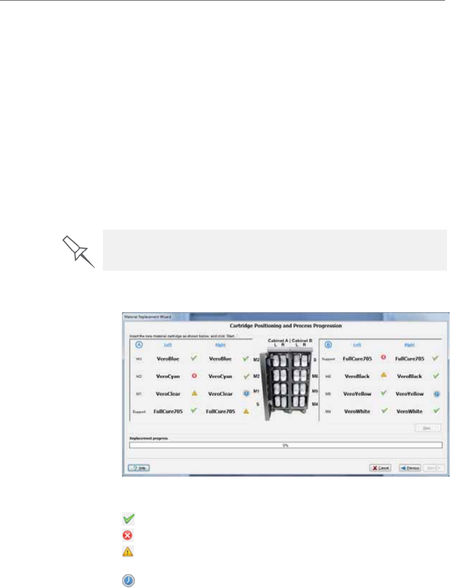
DOC08010 Rev. A (DRAFT 1) 6–13
Stratasys P750K User Guide
7. Chooseȱhowȱthoroughlyȱyouȱwantȱtoȱflushȱoutȱmaterialȱcurrentlyȱinȱtheȱ
system:
•Economy.ȱThisȱcycleȱcanȱbeȱusedȱwhenȱreplacingȱaȱlightȬcoloredȱ
Modelȱmaterialȱwithȱaȱdarkerȱmaterialȱ(suchȱasȱTangoBlack™ȱorȱ
VeroBlack™),ȱorȱifȱtheȱexactȱcolorȱofȱtheȱprintedȱmodelsȱ(inȱtheȱfirstȱ
printȱjobs)ȱisȱunimportant.ȱ
Theȱwizardȱflushesȱtheȱsystemȱwithȱtheȱminimumȱamountȱofȱ
materialȱneededȱtoȱensureȱthatȱmodelsȱhaveȱtheȱmechanicalȱ
propertiesȱofȱtheȱnewȱmaterial.
•Full.ȱUseȱthisȱcycleȱwhenȱtheȱprintedȱmodelsȱmustȱhaveȱtheȱexactȱ
colorȱofȱtheȱnewȱmaterial.
Theȱwizardȱthoroughlyȱflushesȱtheȱfeedȱtubesȱandȱprintȱheadsȱ
neededȱforȱprinting,ȱbasedȱonȱyourȱselectionsȱinȱtheȱpreviousȱ
screens.ȱ
8. ClickȱNextȱtoȱbeginȱtheȱmaterialȱreplacementȱprocessȱinȱtheȱprinter.
TheȱCartridgeȱpositioningȱscreenȱappears,ȱshowingȱyouȱtheȱnewȱlocationȱ
ofȱallȱcartridgesȱinȱtheȱmaterialsȱcabinet.
Figure 6-9: Cartridge placement
Symbols:
Theȱcorrectȱcartridgeȱisȱinȱthisȱslot.
Noȱcartridgeȱ(orȱtheȱincorrectȱcartridge)ȱisȱinȱthisȱslot.
Theȱcartridgeȱinȱthisȱslotȱhasȱinsufficientȱweightȱtoȱcompleteȱtheȱ
materialȱreplacementȱprocess.
Theȱexpirationȱdateȱofȱtheȱcartridgeȱinȱthisȱslotȱhasȱpassed.
9. Replaceȱmaterialȱcartridges,ȱasȱnecessary,ȱaccordingȱtoȱtheȱinstructionsȱ
inȱtheȱwizardȱscreen.
10. ClickȱStart.
There are additional settings that you can select for special purposes (see
Advanced Settings). If necessary, click Advanced Settings before clicking
Next.
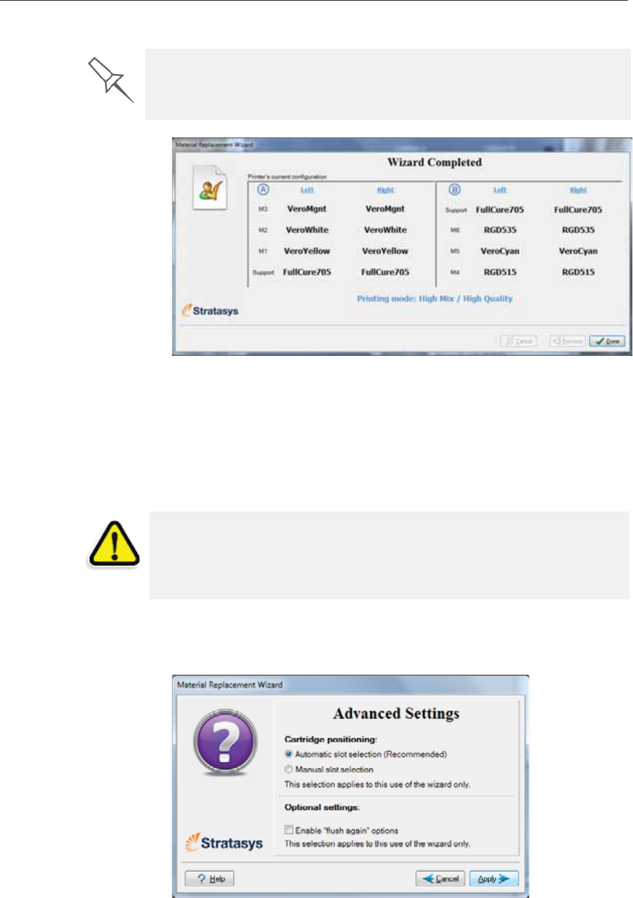
Operating & Maintaining the Stratasys P750K 3D Printer
6–14 DOC08010 Rev. A (DRAFT 1)
11. Readȱtheȱwarningȱmessage,ȱandȱclickȱOK.
Figure 6-10: Final wizard screen
12. ClickȱDoneȱtoȱcloseȱtheȱwizard.
TheȱprinterȬcontrolȱapplicationȱisȱautomaticallyȱupdated,ȱandȱtheȱ
interfaceȱdisplaysȱtheȱnewȱmaterial(s).ȱTheȱObjetȱStudioȱapplicationȱ(onȱ
theȱprinterȬserverȱcomputer)ȱisȱalsoȱupdatedȱandȱdisplaysȱtheȱnewȱ
material(s).
13. Inspectȱtheȱareaȱaroundȱtheȱpurgeȱunitȱandȱcleanȱit,ȱifȱnecessary.
Advanced
Settings TheȱAdvancedȱSettingsȱdialogȱboxȱenablesȱyouȱtoȱconfigureȱtheȱMaterialȱ
Replacementȱwizardȱforȱspecialȱpurposes.ȱIfȱnecessary,ȱclickȱAdvanced
SettingsȱinȱtheȱMaterialȱReplacementȱOptionsȱscreenȱbeforeȱclickingȱNext.
Figure 6-11: Advanced Replacement settings
If you continue, you must complete the material replacement process
before you can produce models. To replace material at another time, click
Cancel. If you continue (by clicking OK) and you do not complete the
process, you will need to run the wizard again before producing models.
CAUTION: Dispose of all material cartridges in accordance with all
applicable laws and regulations. If necessary, the cartridges can be
disassembled for recycling. If this is done, protect the person handling
the cartridges from direct exposure to uncured resins.
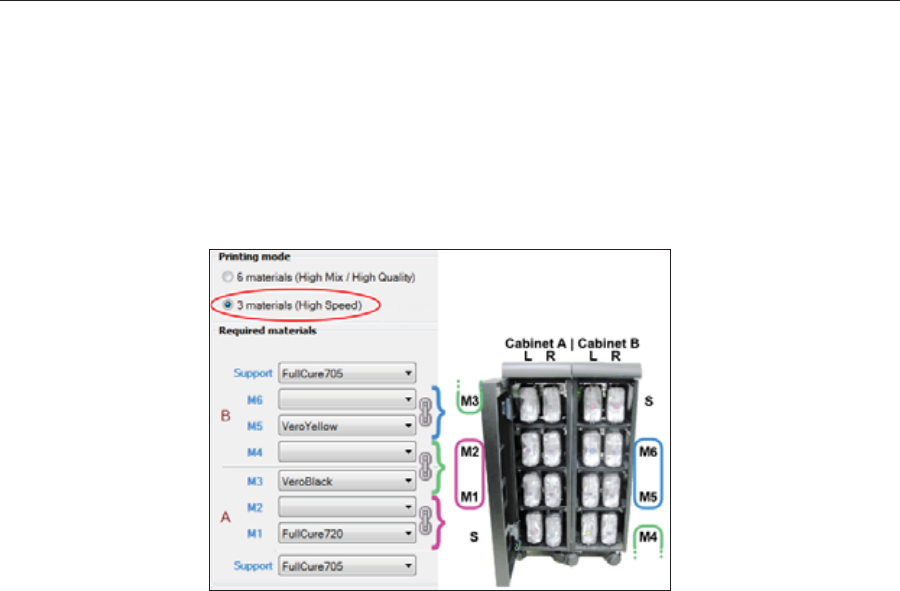
DOC08010 Rev. A (DRAFT 1) 6–15
Stratasys P750K User Guide
Positioning Byȱdefault,ȱAutomaticȱslotȱselectionȱdeterminesȱtheȱbestȱslotȱlocationsȱforȱtheȱ
cartridgesȱinȱtheȱmaterialsȱcabinet,ȱbasedȱonȱmaterialsȱcurrentlyȱinȱtheȱ
system.ȱThisȱensuresȱminimumȱflushingȱofȱmaterialsȱcurrentlyȱloaded.ȱIfȱ
thereȱisȱaȱspecialȱneedȱtoȱloadȱcartridgesȱinȱcertainȱslotȱlocations,ȱselectȱ
Manual slot selection.
AfterȱclickingȱApply,ȱtheȱMaterialȱReplacementȱOptionsȱscreenȱappears,ȱbutȱ
now,ȱeachȱmaterialȱselectionȱboxȱcorrespondsȱtoȱoneȱofȱtheȱcartridgeȱlevelsȱ
inȱtheȱmaterialsȱcabinet.
Figure 6-12: Manual cartridge placement
Flush Again TheȱflushingȱcycleȱyouȱselectȱinȱtheȱMaterialȱReplacementȱOptionsȱscreenȱ
determinesȱhowȱthoroughlyȱtoȱflushȱoutȱmaterialȱcurrentlyȱinȱtheȱsystem.ȱ
AfterȱselectingȱtheȱEconomyȱcycleȱandȱcompletingȱtheȱwizard,ȱyouȱmightȱ
decideȱthatȱyouȱrequireȱaȱmoreȱthoroughȱflushing,ȱtoȱensureȱaccurateȱ
modelȱcolor.ȱOr,ȱyouȱmayȱnoticeȱthatȱprintedȱmodelsȱareȱnotȱsatisfactoryȱ
becauseȱtheyȱcontainȱtracesȱofȱtheȱpreviousȱmaterial.ȱIfȱso,ȱyouȱcanȱflushȱoutȱ
moreȱmaterial,ȱsoȱthatȱtheȱnextȱmodelsȱwillȱbeȱprintedȱwithȱpureȱmaterial.
Afterȱselectingȱtheȱ“flushȱagain”ȱoptionȱandȱclickingȱApply,ȱtheȱMaterialȱ
ReplacementȱOptionsȱscreenȱappears,ȱwhereȱyouȱselectȱtheȱaffectedȱ
material(s)ȱtoȱbeȱflushed.
Note: Select only the materials you need to flush.
Operating & Maintaining the Stratasys P750K 3D Printer
6–16 DOC08010 Rev. A (DRAFT 1)
Keeping the Printer in Idle Mode
Betweenȱprintingȱjobs,ȱtheȱStratasysȱP750Kȱprinterȱcanȱbeȱkeptȱonȱforȱupȱtoȱ
oneȱweek.ȱIfȱtheȱprinterȱwillȱnotȱbeȱusedȱforȱmoreȱthanȱaȱweek,ȱuseȱtheȱ
Shutdownȱwizardȱtoȱautomaticallyȱperformȱtheȱproceduresȱthatȱmustȱbeȱ
doneȱbeforeȱturningȱoffȱtheȱprinterȱ(seeȱ“ShuttingȱDownȱtheȱPrinter,”ȱ
below).
Whenȱtheȱprinterȱstopsȱproducingȱmodels,ȱtheȱprinterȱsoftwareȱ
automaticallyȱreducesȱtheȱtemperatureȱofȱtheȱprintȱheadsȱasȱfollows:
Note: The printer mode is indicated in the green field on the left of the
interface (see figures 6-3, 6-4 and 6-5 on pages 3, 6 and 8).
If,ȱafterȱprintingȱaȱjob,ȱyouȱknowȱthatȱtheȱprinterȱwillȱnotȱbeȱusedȱforȱ10ȱ
hoursȱorȱmore,ȱyouȱcanȱimmediatelyȱturnȱoffȱtheȱheatingȱofȱtheȱprintȱheadsȱ
byȱputtingȱtheȱprinterȱintoȱIdleȱmode.
To put the printer into Idle mode:
¾FromȱtheȱFileȱmenuȱ(inȱtheȱprinterȱinterface)ȱclickȱExit.
Note: The printer remains in Idle mode until you open the Stratasys printer
application and begin printing again.
Time after printing Mode Change in heating of print heads
firstȱ15ȱminutes Standbyȱ1none
nextȱ10ȱhours Standbyȱ2heatingȱreducedȱ(toȱroomȱtemp.)
afterȱ10ȱhours Idle heatingȱstopped
When the printer is in Idle mode, do not turn it off. It can remain in this
mode—with the cover closed—for up to a week. For longer periods, shut
down the printer by running the Shutdown wizard (see below).
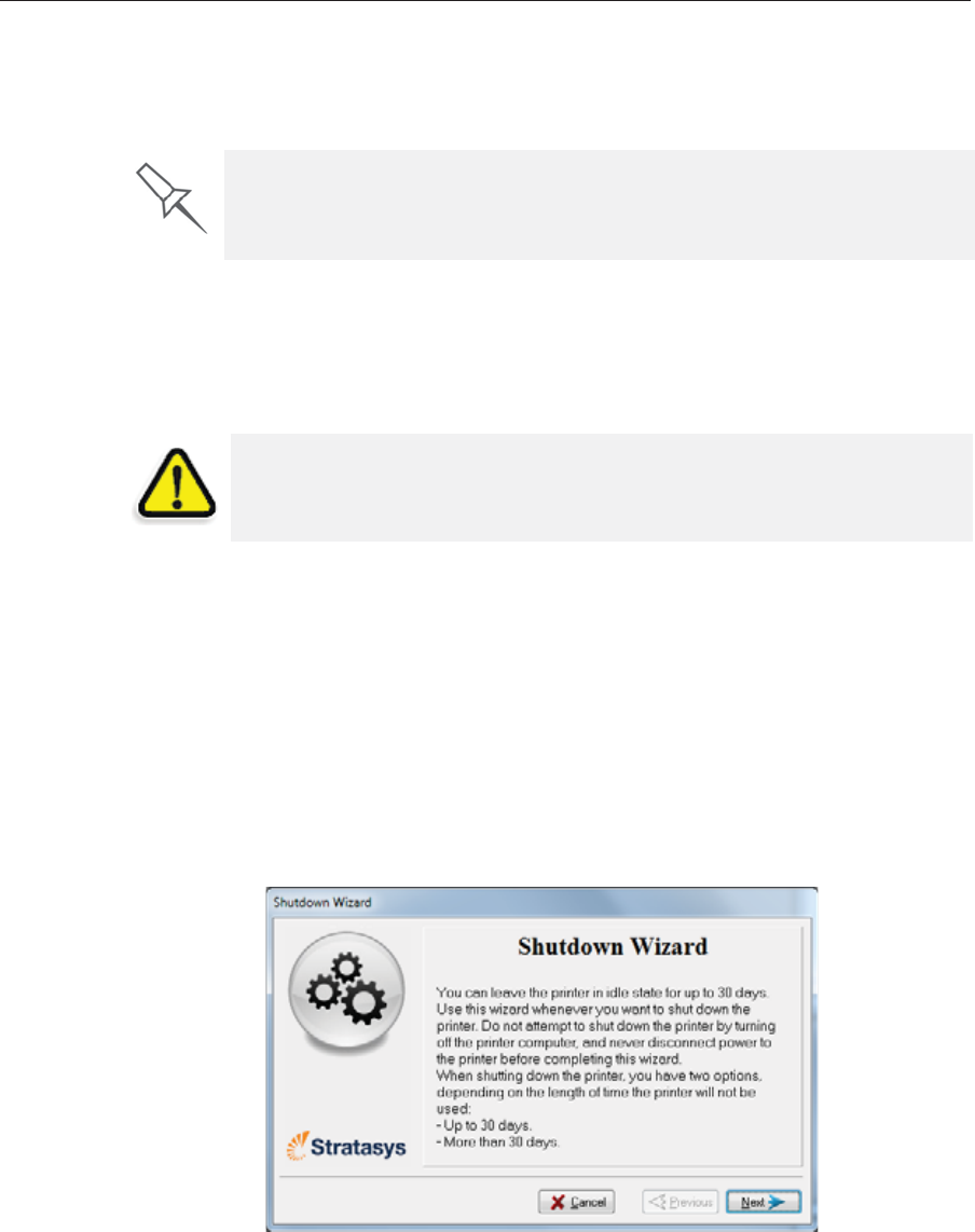
DOC08010 Rev. A (DRAFT 1) 6–17
Stratasys P750K User Guide
Shutting Down the Printer
YouȱonlyȱneedȱtoȱshutȱdownȱtheȱStratasysȱprinterȱifȱitȱwillȱnotȱbeȱusedȱforȱaȱ
weekȱorȱmore.ȱOtherwise,ȱtheȱprinterȱcanȱremainȱon,ȱinȱIdleȱmode.ȱ
Toȱproperlyȱshutȱdown,ȱtheȱprinterȱneedsȱtoȱperformȱseveralȱprocesses.ȱ
TheseȱareȱcontrolledȱbyȱtheȱShutdownȱwizard.ȱDoȱnotȱattemptȱtoȱshutȱ
downȱtheȱprinterȱbyȱsimplyȱclosingȱtheȱcomputerȱinterfaceȱ(theȱprinterȬ
controlȱapplication),ȱandȱneverȱdisconnectȱpowerȱtoȱtheȱprinterȱbeforeȱ
completingȱthisȱwizard.
Dependingȱonȱtheȱlengthȱofȱtimeȱtheȱprinterȱwillȱnotȱbeȱused,ȱyouȱcanȱ
chooseȱbetweenȱaȱshortȱshutdownȱprocedure,ȱandȱaȱmoreȱthoroughȱ
procedure.
•Upȱtoȱ30ȱdays:ȱTheȱwizardȱemptiesȱtheȱprintȱblockȱofȱModelȱandȱ
Supportȱmaterial,ȱtoȱpreventȱleaks.ȱThisȱtakesȱaboutȱ10ȱminutes.
•Moreȱthanȱ30ȱdays:ȱTheȱwizardȱemptiesȱtheȱprintȱblock,ȱthenȱflushesȱ
theȱsystemȱwithȱcleaningȱfluid.ȱThisȱtakesȱupȱtoȱ75ȱminutes,ȱandȱyouȱ
mustȱbeȱpresentȱtoȱloadȱcleaningȬfluidȱcartridgesȱwhenȱinstructed.ȱ
To run the Shutdown wizard:
1. StartȱtheȱShutdownȱwizardȱfromȱtheȱOptionsȱmenu.
Figure 6-13: Shutdown wizard, opening screen
2. ClickȱNext.
The Shutdown process flushes printing materials from printer components.
To avoid flushing out valuable material, make sure to print models at least
once a week. Many printer operators use this opportunity to print customer
samples or test models.
CAUTION: Not using the printer for an extended period without first
running the wizard can cause serious damage to print heads and other
expensive printer parts.
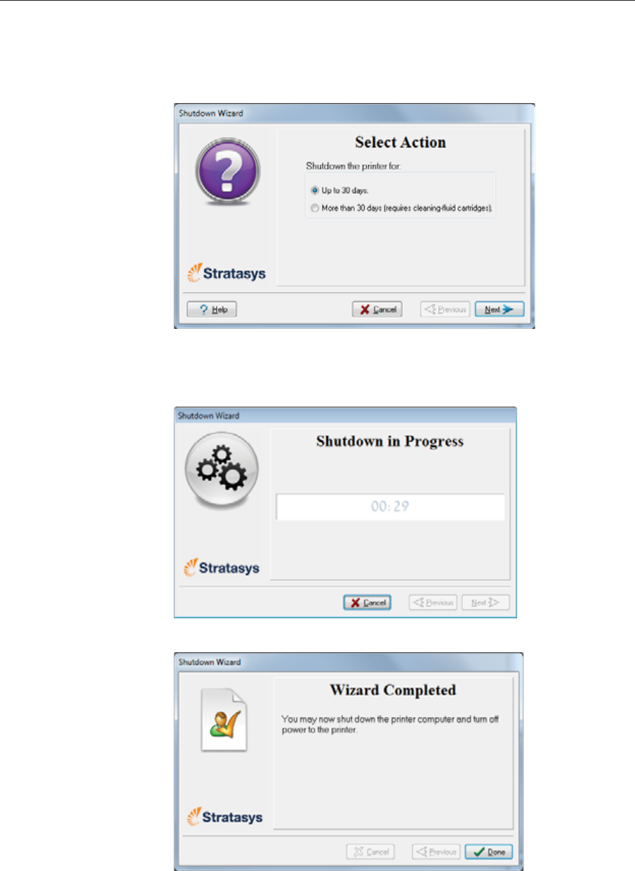
Operating & Maintaining the Stratasys P750K 3D Printer
6–18 DOC08010 Rev. A (DRAFT 1)
3. Chooseȱtheȱappropriateȱoptionȱforȱtheȱlengthȱofȱtimeȱthatȱtheȱprinterȱ
willȱnotȱbeȱused—lessȱorȱmoreȱthanȱ30ȱdays.
Note: Before selecting More than 30 days, make sure that cleaning-fluid
are available.
Figure 6-14: Shutdown options
4. Inȱtheȱnextȱscreen,ȱverifyȱthatȱtheȱtrayȱisȱemptyȱandȱclickȱNext.
Theȱshutdownȱprocedureȱbegins.
Figure 6-15: Shutdown progress screen
Figure 6-16: Final Shutdown wizard screen
5. Afterȱtheȱprinterȱcomputerȱshutsȱdown,ȱturnȱoffȱtheȱmainȱpowerȱswitchȱ
atȱtheȱbackȱofȱtheȱprinter.

DOC08010 Rev. A (DRAFT 1) 6–19
Stratasys P750K User Guide
Maintaining the Printer
Theȱperformanceȱofȱroutineȱmaintenanceȱtasksȱisȱessentialȱforȱgettingȱ
satisfactoryȱresultsȱfromȱStratasysȱ3Dȱprinters.ȱPerformȱtheȱtasksȱatȱ
specifiedȱintervalsȱforȱoptimumȱperformance.
Routine
Maintenance
Schedule
ȱ
Frequency Task For More Information
Beforeȱ/ȱafterȱprinting CheckȱUVȱlampȱ
overheatingȱindicator. Seeȱ“UVȱLampȱCheck”ȱ
onȱpage 20.
Beforeȱ/ȱafterȱprinting Cleanȱtheȱprintȱheadsȱ
andȱtheȱrollerȱsurface. Seeȱ“CleaningȱtheȱPrintȱ
HeadsȱandȱtheȱRoller”ȱ
onȱpage 20.
Daily Cleanȱandȱinspectȱtheȱ
wiper. Seeȱ“Cleaningȱandȱ
ReplacingȱtheȱWiper”ȱ
onȱpage 23.
Weekly PerformȱtheȱPatternȱtest. Seeȱ“PatternȱTest”ȱonȱ
page 25.
Weekly—whenȱprintingȱ
withȱMED610
CalibrateȱtheȱUVȱ
intensity.
Seeȱ“Testingȱandȱ
CalibratingȱtheȱUVȱ
Lamps”ȱonȱpage 53.
Weekly Cleanȱtheȱrollerȱwasteȱ
collector. Seeȱ“CleaningȱtheȱRollerȱ
WasteȱCollectorȱandȱ
InspectingȱtheȱRollerȱ
Scraper”ȱonȱpage 27.
Everyȱ300ȱhoursȱofȱ
printingȱ(Aȱreminderȱ
messageȱappears.)
CalibrateȱtheȱUVȱ
intensity. Seeȱ“Testingȱandȱ
CalibratingȱtheȱUVȱ
Lamps”ȱonȱpage 53.
Everyȱ300ȱhoursȱofȱ
printingȱ(Aȱreminderȱ
messageȱappears.)
Optimizeȱtheȱprintȱ
heads. Seeȱ“Optimizingȱ
(Calibrating)ȱPrintȱ
Heads”ȱonȱpage 35.
Monthly,ȱandȱafterȱ
replacingȱprintȱheads Checkȱtheȱalignmentȱofȱ
theȱprintȱheads. Seeȱ“AligningȱtheȱPrintȱ
Heads”ȱonȱpage 32.
Monthly Restartȱtheȱprinterȱ
computer.
Monthly Inspectȱtheȱexhaustȱ
systemȱ(duct,ȱfan,ȱ
connections).
MonthlyȱCalibrateȱtheȱloadȱcells. Seeȱ“Calibratingȱtheȱ
LoadȱCells”ȱonȱpage 59.
Everyȱ3500ȱhoursȱofȱ
printingȱorȱeveryȱtwoȱ
years
Preventiveȱmaintenanceȱ
visitȱbyȱauthorizedȱ
serviceȱengineer.
ContactȱyourȱStratasysȱ
serviceȱprovider.
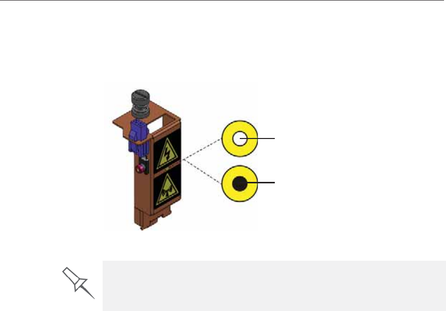
Operating & Maintaining the Stratasys P750K 3D Printer
6–20 DOC08010 Rev. A (DRAFT 1)
UV Lamp
Check AȱheatȬsensitiveȱlabelȱisȱfixedȱtoȱtheȱUVȱlampȱcoversȱasȱaȱwarningȱagainstȱ
overheating.ȱItsȱcenterȱchangesȱfromȱwhiteȱtoȱblackȱifȱtheȱtemperatureȱofȱ
theȱcoverȱreachesȱ65 °Cȱ(150 °F).ȱIfȱthisȱoccurs,ȱdoȱnotȱuseȱtheȱprinter,ȱandȱ
callȱyourȱserviceȱprovider.ȱAsȱaȱprecaution,ȱitȱisȱrecommendedȱthatȱyouȱ
checkȱtheȱlabelȱbeforeȱandȱafterȱprinting.ȱ
Figure 6-17: Heat-sensitive label on UV lamp cover
Cleaning the
Print Heads
and the Roller
Periodicȱinspectionȱandȱcleaningȱofȱtheȱorificeȱplatesȱonȱtheȱbottomȱofȱtheȱ
printȱblockȱensuresȱthatȱtheȱprintȱnozzlesȱareȱnotȱclogged.ȱAȱwizardȱguidesȱ
youȱthroughȱtheȱprocedure,ȱandȱadjustsȱcomponentsȱofȱtheȱprinterȱtoȱ
enableȱyouȱtoȱperformȱit.ȱThisȱprocedureȱtakesȱaboutȱ20ȱminutes,ȱandȱ
shouldȱbeȱdoneȱatȱtheȱbeginningȱofȱtheȱworkȱdayȱorȱbeforeȱaȱbigȱprintingȱ
job.
To clean the print heads and the roller:
1. Prepare—
•isopropanolȱ(IPA—isopropylȱalcohol)ȱorȱethanolȱ(ethylȱalcohol)
•disposableȱcleaningȱgloves
•aȱsuppliedȱcleaningȱclothȱorȱequivalent
•aȱmirror
2. StartȱtheȱHeadȱCleaningȱwizardȱfromȱtheȱOptionsȱmenuȱ(seeȱfigure 6Ȭ22ȱ
onȱpage 23).
Normal
Overheating
problem
If the UV lamp continues to overheat, and the temperature around the lamp
reaches 90 °C (194 °F), a heat fuse cuts the power to the UV lamp and the
motion motors. In the unlikely event that this occurs, the printer cannot be
used until it is serviced by an authorized service engineer.
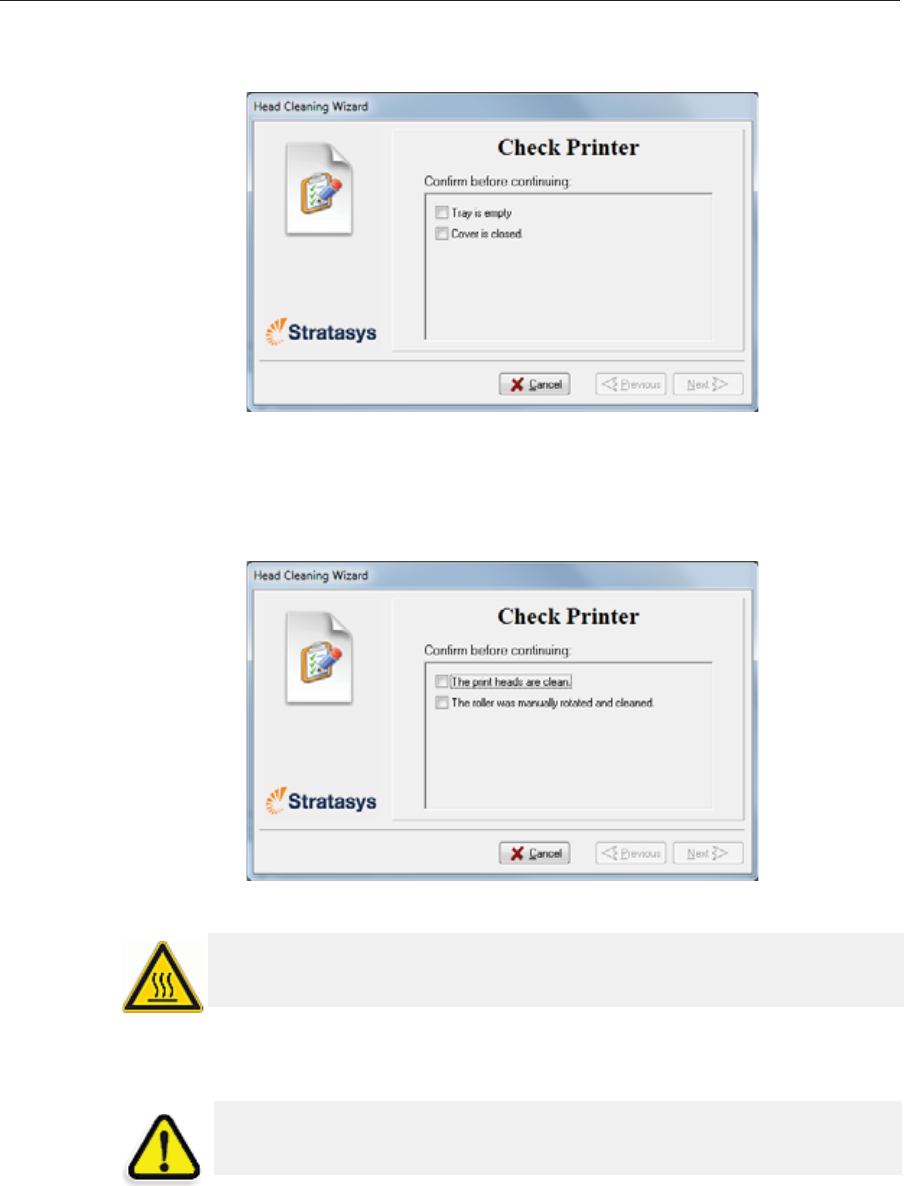
DOC08010 Rev. A (DRAFT 1) 6–21
Stratasys P750K User Guide
3. Followȱtheȱinstructionsȱonȱtheȱwizardȱscreens,ȱandȱselectȱtheȱ
confirmationȱcheckȱboxes.
Figure 6-18: Head cleaning procedure—wizard screen
4. ClickȱNext.ȱ
Theȱprinterȱpreparesȱforȱyouȱtoȱcleanȱtheȱprintȱheads.
5. Whenȱtheȱfollowingȱscreenȱappears,ȱopenȱtheȱcover.
Figure 6-19: Head cleaning wizard—steps 5–11
6. Placeȱtheȱmirrorȱonȱtheȱbuildȱtray.
7. Putȱonȱtheȱgloves.
8. Soakȱtheȱcleaningȱclothȱwithȱalcohol.
WARNING: The print head orifice plates (bottom surface) might be hot,
so proceed with caution.
CAUTION: Uncured printing material on the print heads might cause
skin irritation. Use disposable cleaning gloves to protect your hands.
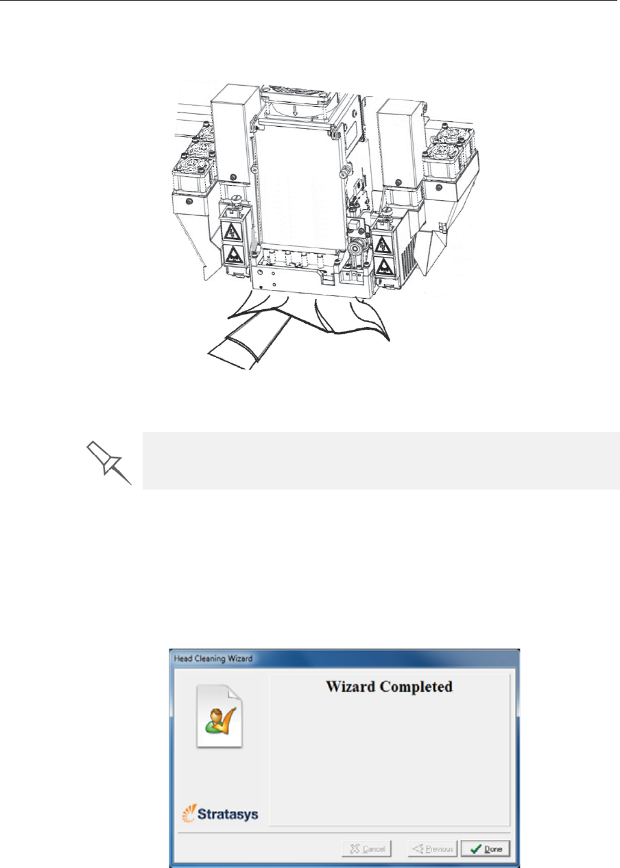
Operating & Maintaining the Stratasys P750K 3D Printer
6–22 DOC08010 Rev. A (DRAFT 1)
9. Cleanȱtheȱorificeȱplates,ȱwithȱaȱbackȬandȬforthȱmotionȱ(seeȱfigure 6Ȭ20).ȱ
Useȱtheȱmirrorȱtoȱmakeȱsureȱthatȱyouȱhaveȱremovedȱallȱofȱtheȱresidueȱ
material.
Figure 6-20: Cleaning the heads
10. Cleanȱtheȱentireȱrollerȱsurface,ȱbyȱrotatingȱitȱasȱyouȱclean.
11. Whenȱyouȱhaveȱfinishedȱcleaning,ȱselectȱtheȱconfirmationȱcheckȱboxesȱ
inȱtheȱwizardȱscreenȱ(seeȱfigure 6Ȭ19)ȱandȱclickȱNext.
12. Removeȱtheȱcleaningȱmaterialsȱfromȱtheȱprinterȱandȱcloseȱtheȱcover.ȱ
13. Selectȱtheȱconfirmationȱcheckȱboxesȱinȱtheȱwizardȱscreenȱandȱclickȱ
Next.
TheȱheadȬpurgeȱcycleȱbegins.ȱWhenȱthisȱisȱcomplete,ȱtheȱfinalȱwizardȱ
screenȱappears.
Figure 6-21: Head-cleaning wizard—final screen
14. ClickȱDoneȱtoȱcloseȱtheȱwizard.
Use this opportunity to clean the glass lens on the UV lamps.
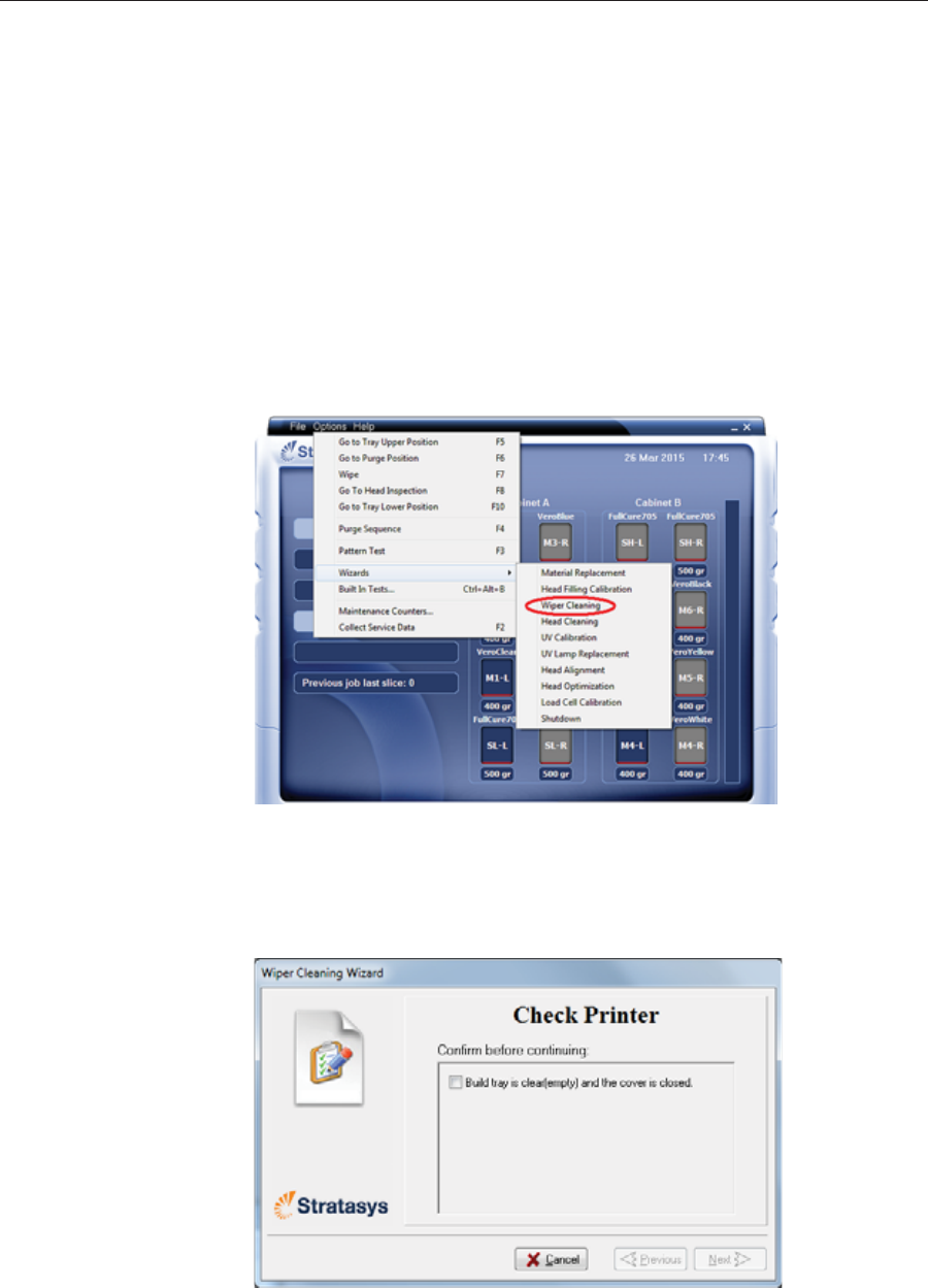
DOC08010 Rev. A (DRAFT 1) 6–23
Stratasys P750K User Guide
Cleaning and
Replacing the
Wiper
Aȱrubberȱwiperȱremovesȱexcessȱmaterialȱfromȱtheȱprintȱheadsȱafterȱtheȱ
purgeȱsequence.ȱThisȱisȱdoneȱautomaticallyȱbeforeȱeachȱprintȱjob,ȱandȱ
performedȱmanuallyȱduringȱmaintenanceȱtasks.ȱYouȱshouldȱcleanȱtheȱ
wiperȱandȱsurroundingȱareaȱatȱleastȱonceȱaȱweek.ȱIfȱtheȱwiperȱisȱdamagedȱ
orȱworn,ȱreplaceȱit.
To inspect and clean the wiper:
1. Prepare—
•isopropanolȱ(IPA—isopropylȱalcohol)ȱorȱethanolȱ(ethylȱalcohol)
•disposableȱcleaningȱgloves
•theȱsuppliedȱcleaningȱclothȱorȱequivalent
•aȱspareȱwiper
2. StartȱtheȱWiperȱCleaningȱwizardȱfromȱtheȱOptionsȱmenu.
Figure 6-22: Starting the Wiper Cleaning wizard
3. Inȱtheȱopeningȱwizardȱscreen,ȱclickȱNext.
4. Makeȱsureȱthatȱtheȱbuildȱtrayȱisȱempty,ȱandȱcloseȱtheȱprinterȱcover.
ConfirmȱthisȱinȱtheȱwizardȱscreenȱandȱclickȱNext.
Figure 6-23: Wiper Cleaning procedure—step 4
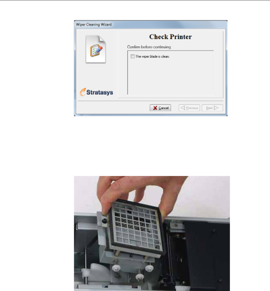
Operating & Maintaining the Stratasys P750K 3D Printer
6–24 DOC08010 Rev. A (DRAFT 1)
5. Whenȱtheȱfollowingȱscreenȱappears,ȱopenȱtheȱcover.
Figure 6-24: Wiper Cleaning wizard during steps 6–10
6. Putȱonȱtheȱcleaningȱgloves.
7. Usingȱaȱgenerousȱamountȱofȱalcoholȱonȱtheȱcleaningȱcloth,ȱremoveȱanyȱ
materialȱremainingȱonȱtheȱwiperȱandȱtheȱsurroundingȱarea.
8. Removeȱanyȱpiecesȱofȱwasteȱmaterialȱcollectedȱinȱtheȱpurgeȱunit.ȱIfȱ
necessary,ȱremoveȱtheȱwasteȱcollectorȱtoȱcleanȱit.ȱWipeȱtheȱrubberȱseal.
Figure 6-25: Purge unit waste collector
Note: When returning the waste collector to the purge unit, make sure to
insert it as shown.
9. Inspectȱtheȱwiper.ȱ
Ifȱtheȱwiperȱisȱscratched,ȱtornȱorȱworn,ȱorȱifȱyouȱcannotȱcleanȱitȱ
completely,ȱreplaceȱit.
a. Graspȱitȱandȱpullȱitȱupȱandȱoutȱofȱitsȱbracket.ȱ
b. Insertȱtheȱnewȱwiperȱblade,ȱmakingȱsureȱthatȱitȱisȱstraightȱandȱsecuredȱ
wellȱonȱbothȱsides.
10. Inȱtheȱwizardȱscreenȱ(seeȱfigure 6Ȭ24),ȱconfirmȱthatȱtheȱwiperȱbladeȱisȱ
clean,ȱandȱclickȱNext.
11. Removeȱallȱtoolsȱandȱcleaningȱmaterialsȱfromȱtheȱprinter,ȱandȱcloseȱtheȱ
cover.
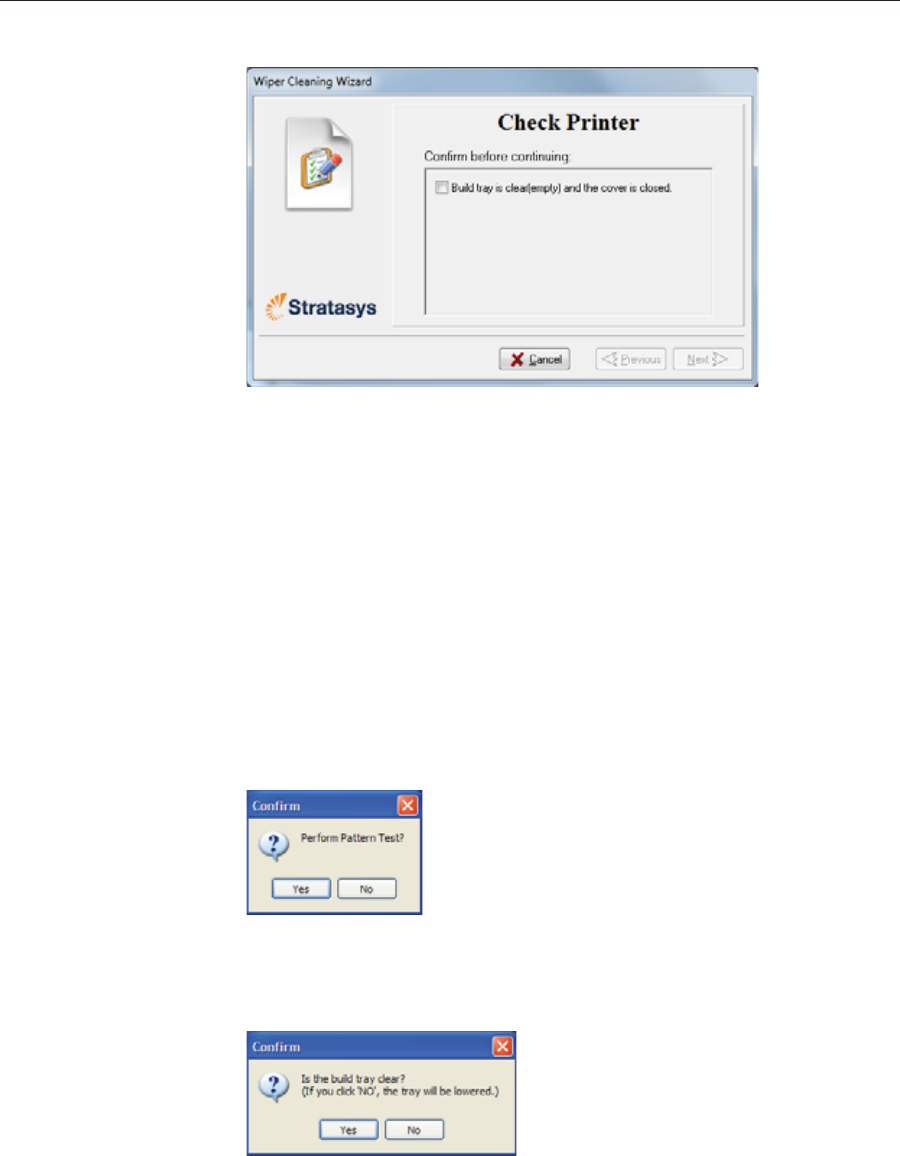
DOC08010 Rev. A (DRAFT 1) 6–25
Stratasys P750K User Guide
12. Confirmȱthisȱinȱtheȱwizardȱscreen,ȱandȱclickȱNext.
Figure 6-26: Confirmation screen
13. ClickȱDoneȱtoȱcloseȱtheȱwizard.
Pattern Test Theȱpatternȱtestȱisȱtheȱbasicȱverificationȱofȱtheȱprinter’sȱabilityȱtoȱproduceȱ
qualityȱmodels,ȱsinceȱitȱdemonstratesȱtheȱconditionȱofȱtheȱnozzlesȱinȱtheȱ
printȱheads.ȱMakeȱsure,ȱtherefore,ȱthatȱyouȱperformȱthisȱtestȱweekly,ȱandȱ
wheneverȱyouȱsuspectȱaȱprintingȱproblem.
To perform the pattern test:
1. Makeȱsureȱthatȱtheȱbuildȱtrayȱisȱempty.
2. Prepareȱaȱsheetȱofȱpinkȱpaper—AȬ4ȱorȱLetterȱsize.
3. Inȱtheȱprinter,ȱtapeȱtheȱpinkȱpaperȱtoȱtheȱsurfaceȱleftȱofȱtheȱbuildȱtray.
4. PressȱF3,ȱorȱopenȱtheȱOptionsȱmenuȱandȱselectȱPattern Test.
Figure 6-27: Pattern Test confirmation
5. Ifȱtheȱbuildȱtrayȱisȱnotȱclear,ȱclickȱNoȱinȱtheȱfollowingȱdialogȱbox.
Thisȱlowersȱtheȱbuildȱtray,ȱsoȱthatȱmodelsȱonȱtheȱtrayȱareȱnotȱdamaged.
Figure 6-28: Build tray (Z) level adjustment
Theȱprinterȱprintsȱaȱseriesȱofȱlinesȱonȱtheȱtestȱpaperȱ(seeȱnextȱfigure).
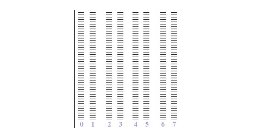
Operating & Maintaining the Stratasys P750K 3D Printer
6–26 DOC08010 Rev. A (DRAFT 1)
Figure 6-29: Sample Pattern Test
6. Carefullyȱinspectȱtheȱtestȱpaperȱtoȱseeȱifȱthereȱareȱmissingȱlines.ȱ
Tooȱmanyȱmissingȱlines,ȱespeciallyȱifȱtheyȱareȱinȱtheȱsameȱarea,ȱ
indicatesȱthatȱtheȱqualityȱofȱprintingȱwhenȱproducingȱmodelsȱwillȱbeȱ
poor.ȱIfȱthisȱisȱtheȱcase,ȱseeȱ“ImprovingȱPrintȱQuality,”ȱbelow.
Note: Acceptable model quality is subjective, and depends on the type
and scale (size) of the models produced.As a rule, however, more than 10
missing lines in one area of a column is considered unacceptable.
Improving
Print Quality Ifȱyouȱsuspectȱthatȱprintȱqualityȱisȱpoor,ȱperformȱtheȱpatternȱtestȱ(seeȱ
“PatternȱTest”ȱonȱpage 25).ȱIfȱtheȱresultsȱareȱpoor,ȱuseȱtheȱfollowingȱ
procedureȱtoȱimproveȱprintȱquality.
If the results of the last pattern test are poor:
1. FromȱtheȱOptionsȱmenu,ȱselectȱPurge Sequence,ȱorȱpressȱF4.
2. Inȱtheȱconfirmationȱdialogȱbox,ȱclickȱYes.
TheȱprintȱheadsȱareȱpurgedȱofȱModelȱandȱSupportȱmaterial,ȱandȱtheȱ
wiperȱremovesȱexcessȱmaterialȱfromȱthem.
3. Repeatȱtheȱpurgeȱsequence.
4. Performȱtheȱpatternȱtest.
If the results of the pattern test are still poor:
1. Manuallyȱcleanȱtheȱprintȱheadsȱ(seeȱ“CleaningȱtheȱPrintȱHeadsȱandȱtheȱ
Roller”ȱonȱpage 20).
2. Performȱtheȱpurgeȱsequence.
3. Performȱtheȱpatternȱtest.
If the results of the pattern test are still poor:
1. Carefullyȱcleanȱtheȱprintȱheadsȱagain,ȱmakingȱsureȱthereȱisȱnoȱresidueȱ
leftȱonȱthem.
2. Performȱtheȱpurgeȱsequence.
3. Performȱtheȱpatternȱtest.
If the results of the pattern test are still poor:
¾Optimizeȱtheȱprintȱheadsȱandȱreplaceȱfaultyȱprintȱheads,ȱifȱnecessaryȱ
(seeȱ“Optimizingȱ(Calibrating)ȱPrintȱHeads”ȱonȱpage 35).

DOC08010 Rev. A (DRAFT 1) 6–27
Stratasys P750K User Guide
Cleaning the
Roller Waste
Collector and
Inspecting the
Roller Scraper
Theȱrollerȱwasteȱcollectorȱremovesȱwasteȱmaterialȱscrapedȱfromȱtheȱroller.ȱ
Suctionȱremovesȱthisȱwasteȱtoȱtheȱprinter’sȱwasteȱcontainer.ȱ
Thisȱassemblyȱshouldȱbeȱcleanedȱweeklyȱtoȱpreventȱaȱblockageȱinȱtheȱtubesȱ
leadingȱtoȱtheȱwasteȱcontainer,ȱsoȱthatȱwasteȱmaterialȱdoesȱnotȱoverflowȱ
intoȱtheȱprinter.
To clean the roller waste collector:
1. Prepare—
•M2.5ȱandȱM2ȱAllen®ȱkeys
•disposableȱcleaningȱgloves
•isopropanolȱ(IPA—isopropylȱalcohol)ȱorȱethanolȱ(ethylȱalcohol)
•cleaningȱcloth
•cottonȱswabsȱ(QȬtipsȱorȱsimilar)
2. Putȱonȱtheȱgloves.
3. RemoveȱtheȱrightȱUVȬlampȱassembly:
a. DisconnectȱtheȱUVȱpowerȱcableȱandȱtheȱfanȱpowerȱcable.
Figure 6-30: Disconnecting the right UV assembly
b. RemoveȱtheȱscrewȱthatȱsecuresȱtheȱrightȱUVȱlamp,ȱandȱthenȱpullȱandȱ
liftȱupȱtheȱUVȱlamp.
Fan power
connector
UV Power
connector
Screw
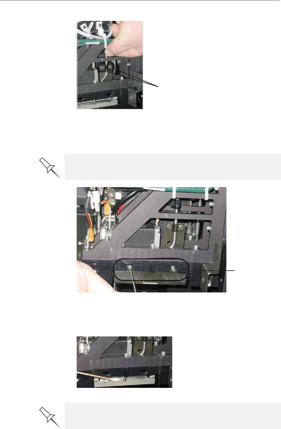
Operating & Maintaining the Stratasys P750K 3D Printer
6–28 DOC08010 Rev. A (DRAFT 1)
4. Loosenȱtheȱtwoȱscrewsȱsecuringȱtheȱsuctionȱtubeȱonȱtheȱprintȱblock.
Figure 6-31: Lifting the suction tube
5. Liftȱtheȱsuctionȱtubeȱtoȱsecureȱitȱinȱaȱraisedȱposition.
6. Removeȱtheȱtwoȱscrewsȱsecuringȱtheȱcoveringȱofȱtheȱrollerȱwasteȱ
collectorȱandȱremoveȱit.
Figure 6-32: Removing the roller waste collector covering
7. Removeȱtheȱcoveringȱbyȱpullingȱitȱout,ȱandȱthenȱlowerȱit.
8. Cleanȱtheȱrollerȱwasteȱcollectorȱandȱtheȱscraperȱbladeȱsurfaceȱusingȱ
cottonȱswabs.ȱMakeȱsureȱtoȱremoveȱanyȱremainingȱprintingȱmaterials.
Figure 6-33: Cleaning the roller waste collector
Suction tube screws
Be very careful to save the covering screws. These are special screws; if
they are lost, you need to order replacements.
Roller waste
collector screws
Before replacing the covering, you can check the effectiveness of the roller
scraper—see below.
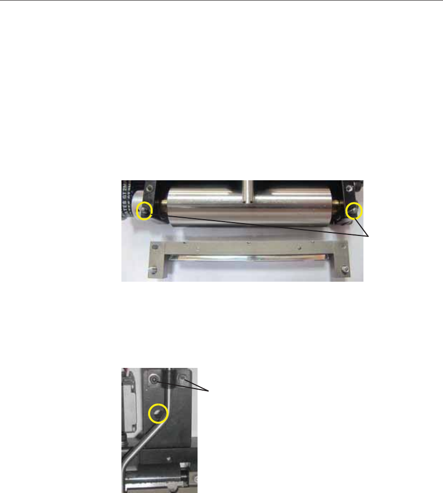
DOC08010 Rev. A (DRAFT 1) 6–29
Stratasys P750K User Guide
To check the effectiveness of the roller scraper:
1. Putȱonȱtheȱcleaningȱgloves.
2. Wetȱaȱclothȱwithȱisopropanol.
3. Useȱtheȱclothȱtoȱwetȱtheȱbottomȱofȱtheȱroller.
4. Turnȱtheȱrollerȱslowlyȱwithȱyourȱhand.ȱAsȱtheȱbladeȱscrapesȱtheȱroller,ȱ
makeȱsureȱtheȱisopropanolȱisȱspreadȱevenlyȱoverȱtheȱentireȱlengthȱofȱ
theȱblade.
5. Inspectȱtheȱroller.ȱIfȱitȱisȱnotȱdry,ȱreplaceȱtheȱblade.ȱ(Seeȱ“Replacingȱtheȱ
RollerȱScraper”ȱonȱpage 30.)
6. Beforeȱreturningȱtheȱrollerȱwasteȱcollectorȱtoȱtheȱprintȱblock,ȱmakeȱsureȱ
thatȱtheȱpinsȱareȱclean.ȱ
Figure 6-34: Roller waste collector pins
To re-assemble the components:
1. Returnȱtheȱrollerȱwasteȱcollectorȱtoȱtheȱprintȱblockȱandȱscrewȱonȱtheȱ
coveringȱ(seeȱfigure 6Ȭ32ȱonȱpage 28).
2. Loosenȱtheȱscrewsȱsecuringȱtheȱsuctionȱtube.
Figure 6-35: Suction tube correctly positioned
3. Lowerȱitȱsoȱthatȱtheȱholeȱinȱtheȱpanelȱbehindȱtheȱsuctionȱtubeȱisȱvisible,ȱ
andȱtightenȱtheȱscrewsȱtoȱsecureȱtheȱtube.ȱ
4. AttachȱtheȱrightȬUVȬlampȱassemblyȱtoȱtheȱprintȱblockȱandȱreconnectȱ
theȱUVȱpowerȱandȱfanȱcables.
Roller waste
collector pins
Securing screws
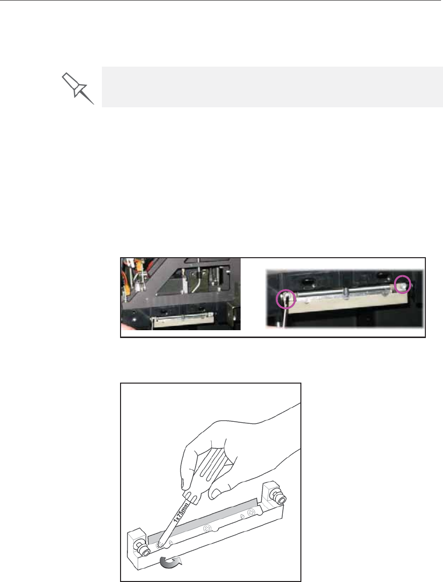
Operating & Maintaining the Stratasys P750K 3D Printer
6–30 DOC08010 Rev. A (DRAFT 1)
Replacing the
Roller Scraper Youȱshouldȱreplaceȱtheȱrollerȱscraperȱblade—
•afterȱ1,000ȱhoursȱofȱprinting.
•ifȱitȱdoesȱnotȱeffectivelyȱkeepȱtheȱrollerȱclean.
To replace the roller scraper:
1. Prepare—
•aȱnewȱrollerȱscraperȱbladeȱ(KITȬ01026ȬS)
•aȱPhillipsȱ1x75ȱmmȱscrewdriver
•M2.5ȱandȱM2ȱAllen®ȱkeys
2. RemoveȱtheȱrightȱUVȱlampȱandȱtheȱrollerȱwasteȱcollectorȱcoveringȱ(seeȱ
stepsȱ3ȱtoȱ6ȱonȱpage 27.)
3. Loosenȱtheȱtwoȱscrewsȱsecuringȱtheȱrollerȱwasteȱcollectorȱandȱpullȱitȱ
out.
Figure 6-36: Removing the roller waste collector
4. Removeȱtheȱscrewsȱthatȱsecureȱtheȱrollerȱscraperȱassembly.ȱ
Figure 6-37: Removing the roller scraper screws
You should periodically test the effectiveness of the roller scraper when you
clean the roller waste collector. See “Cleaning the Roller Waste Collector
and Inspecting the Roller Scraper” on page 27.
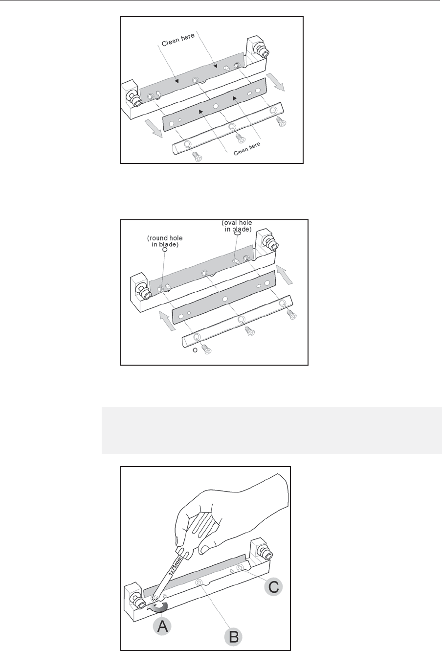
DOC08010 Rev. A (DRAFT 1) 6–31
Stratasys P750K User Guide
Figure 6-38: Removing the old roller scraper blade
5. Removeȱtheȱscraperȱbladeȱandȱdiscardȱit.
6. Placeȱtheȱnewȱscraperȱbladeȱontoȱtheȱpinsȱinȱtheȱholder,ȱasȱshown.ȱ
Figure 6-39: Inserting the new roller scraper blade
7. Insertȱandȱtightenȱtheȱrollerȱscraperȱbladeȱscrews.
Figure 6-40: Tightening the roller scraper screws
Important:
¾Tighten the screws in the order shown in figure 6-40.
¾Use the new screws supplied in the replacement kit.
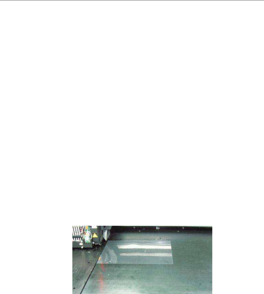
Operating & Maintaining the Stratasys P750K 3D Printer
6–32 DOC08010 Rev. A (DRAFT 1)
8. Afterȱtighteningȱtheȱscrews,ȱinspectȱtheȱbladeȱandȱmakeȱsureȱthatȱitȱisȱ
straight.ȱIfȱnecessary,ȱloosenȱtheȱscrewsȱandȱtightenȱthemȱagain,ȱevenly.
9. ReturnȱtheȱrollerȱwasteȱcollectorȱassemblyȱandȱtheȱrightȱUVȱlampȱtoȱ
theȱprintȱblock.ȱSeeȱstepsȱ6ȱtoȱ4,ȱfromȱpage 29.
Aligning the
Print Heads Youȱshouldȱcheckȱtheȱalignmentȱofȱtheȱprintȱheads—ȱ
•onceȱaȱmonth
•afterȱreplacingȱoneȱorȱmoreȱheads
•ifȱmodelȱqualityȱisȱnotȱacceptableȱevenȱafterȱcleaningȱtheȱorificeȱplateȱonȱ
theȱbottomȱofȱtheȱprintȱblockȱ(seeȱ“CleaningȱtheȱPrintȱHeadsȱandȱtheȱ
Roller”ȱonȱpage 20)
Thisȱprocedureȱtakesȱaboutȱ20ȱminutes.
To check the alignment of the print heads:
1. Prepare—
•aȱtransparencyȱsheet—AȬ4ȱorȱLetterȱsize
•anyȱtypeȱofȱstickyȱtape,ȱtoȱfastenȱtheȱtransparencyȱsheetȱtoȱtheȱbuildȱ
tray
2. StartȱtheȱHeadȱAlignmentȱwizardȱfromȱtheȱOptionsȱmenuȱ(seeȱ
figure 6Ȭ8ȱonȱpage 11).
3. ClickȱNextȱtoȱbegin,ȱandȱcloseȱtheȱcover.
4. Inȱtheȱwizardȱscreen,ȱselectȱtheȱcheckȱboxȱtoȱconfirmȱthatȱtheȱcoverȱisȱ
closed,ȱandȱclickȱNext.
5. Whenȱinstructedȱtoȱdoȱso,ȱplaceȱtheȱtransparencyȱonȱtheȱbuildȱtray—ȱ
nextȱtoȱtheȱleftȱandȱrearȱedgesȱofȱtheȱtray,ȱasȱshownȱinȱtheȱfollowingȱ
figure.
Figure 6-41: Positioning the transparency on the build tray
6. Makeȱsureȱthatȱtheȱtransparencyȱsheetȱisȱlyingȱflat,ȱandȱtapeȱitȱtoȱtheȱ
tray.
7. Inȱtheȱwizardȱscreen,ȱselectȱtheȱcheckȱboxȱtoȱconfirmȱthatȱtheȱ
transparencyȱsheetȱisȱonȱtheȱbuildȱtray,ȱandȱclickȱNext.
Theȱprinterȱprintsȱtheȱheadȱalignmentȱtestȱonȱtheȱtransparency.
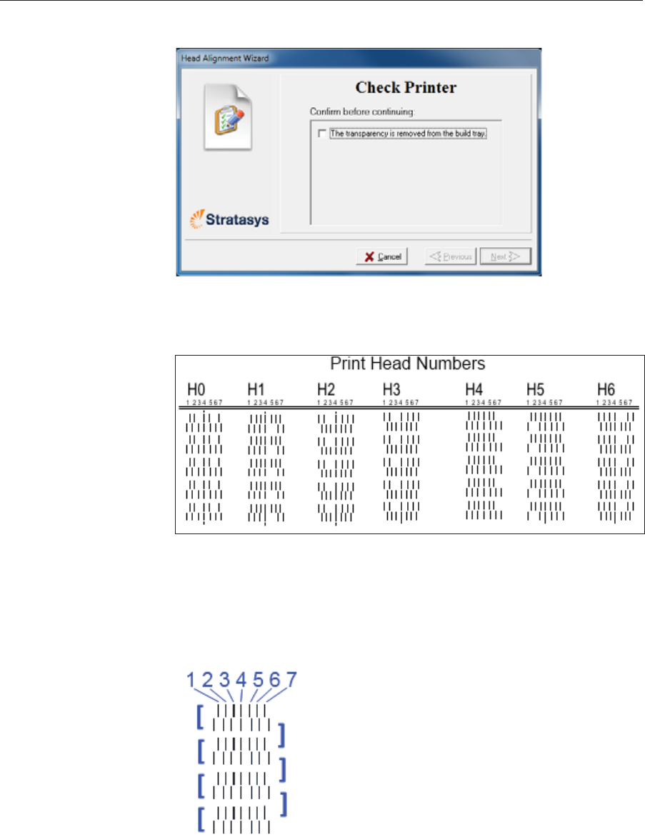
DOC08010 Rev. A (DRAFT 1) 6–33
Stratasys P750K User Guide
8. Whenȱtheȱfollowingȱscreenȱappears,ȱremoveȱtheȱtransparency.
Figure 6-42: Head Alignment wizard—steps 8–10
Theȱtransparencyȱsheetȱisȱprintedȱwithȱsetsȱofȱverticalȱlinesȱinȱsevenȱ
columns,ȱeachȱshowingȱtheȱresultsȱfromȱaȱdifferentȱprintȱhead.
Figure 6-43: Sample head-alignment test
Note: There is no column for head H7 because its alignment is used as a
reference for aligning all other heads.
9. Forȱeachȱcolumnȱofȱlines,ȱuseȱaȱmagnifyingȱglassȱorȱloupeȱtoȱinspectȱ
pairsȱofȱconsecutiveȱrowsȱprintedȱonȱtheȱtransparencyȱtoȱseeȱwhereȱtheȱ
verticalȱlinesȱalign.
Figure 6-44: Comparing rows of alignment lines
Note: It does not matter which pair of lines you inspect, since they were all
printed by the same head. Choose a pair of clearly printed lines for the
inspection. (Since some nozzles may not print clearly, you may have to
inspect several pairs of lines to properly view the alignment.)
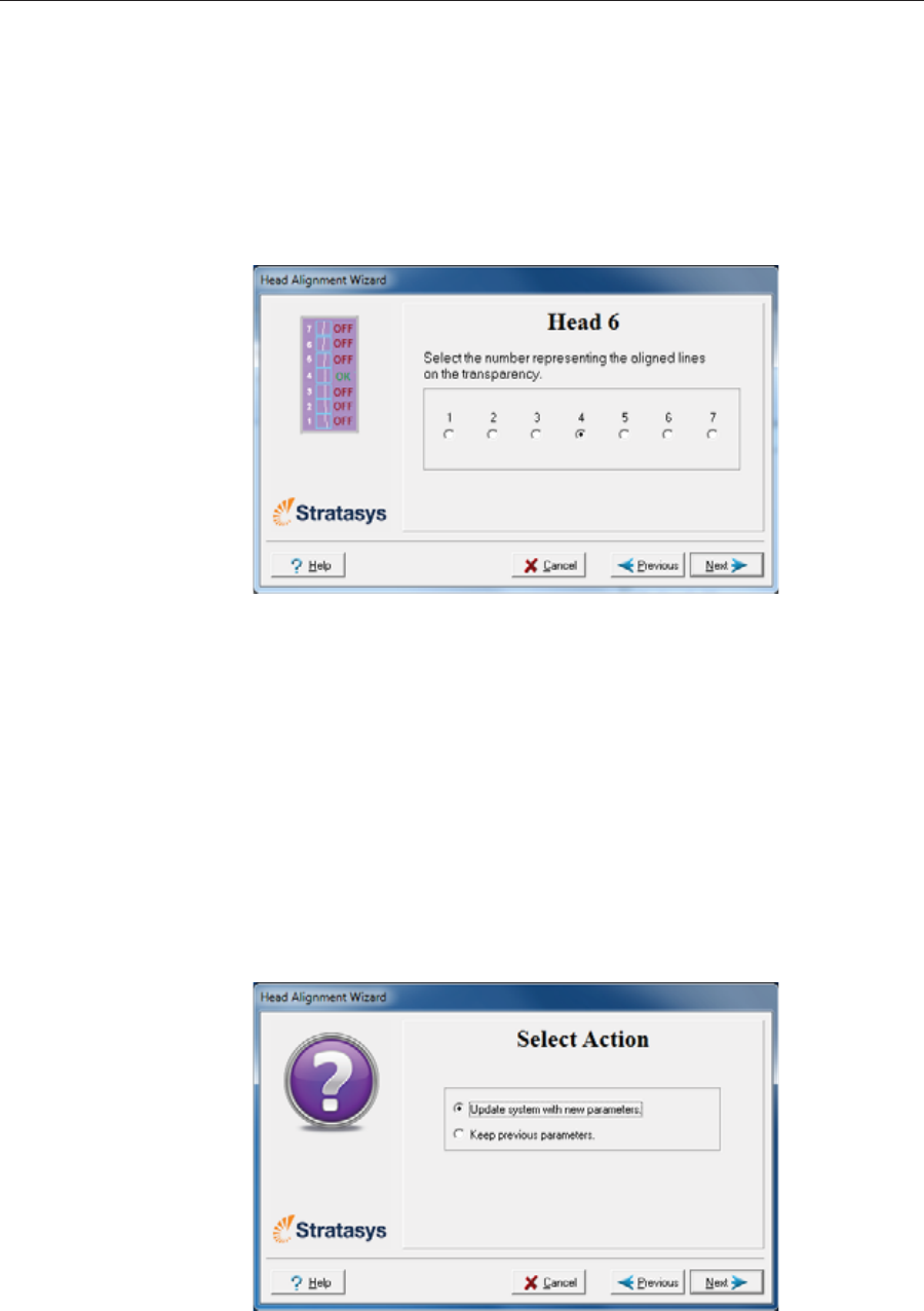
Operating & Maintaining the Stratasys P750K 3D Printer
6–34 DOC08010 Rev. A (DRAFT 1)
Optimumȱheadȱalignmentȱisȱshownȱwhenȱtheȱfourthȱlinesȱinȱtheȱupperȱ
andȱlowerȱrowsȱareȱaligned,ȱasȱinȱfigure 6Ȭ44.ȱInȱtheȱexampleȱshown,ȱnoȱ
changeȱtoȱtheȱheadȱalignmentȱisȱnecessary.ȱIfȱotherȱlinesȱinȱtheȱsetȱareȱ
aligned,ȱyouȱneedȱtoȱchangeȱtheȱalignmentȱofȱthatȱhead—inȱtheȱnextȱ
wizardȱscreens.
10. Inȱtheȱwizardȱscreenȱshownȱinȱfigure 6Ȭ42,ȱselectȱtheȱTransparencyȱ
removedȱcheckȱbox,ȱandȱclickȱNext.
Theȱfirstȱinȱaȱseriesȱofȱalignmentȱscreensȱappears.
Figure 6-45: Head alignment screen
11. InȱtheȱheadȬalignmentȱscreen,ȱselectȱtheȱnumberȱthatȱindicatesȱwhichȱ
linesȱalignȱinȱtheȱupperȱandȱlowerȱrowsȱofȱaȱpairȱonȱtheȱtransparencyȱ
(countingȱfromȱtheȱleft)ȱforȱthisȱprintȱhead.
Note: Because the alignment of the fourth lines is optimum, the number “4”
is selected, by default, in the wizard screen. This does not change the head
alignment. If you select other numbers, the wizard adjusts the head
alignment, accordingly.
12. ClickȱNextȱtoȱdisplayȱtheȱnextȱheadȱalignmentȱscreen,ȱandȱagainȱselectȱ
theȱnumberȱrepresentingȱtheȱmostȱcloselyȱalignedȱverticalȱlinesȱonȱtheȱ
transparencyȱforȱthatȱprintȱhead.
Whenȱyouȱhaveȱfinishedȱaligningȱallȱofȱtheȱheads,ȱtheȱfollowingȱscreenȱ
isȱdisplayed.
Figure 6-46: Parameter update confirmation
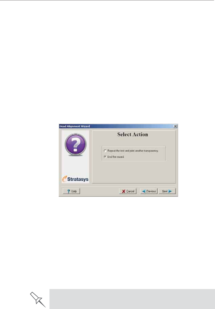
DOC08010 Rev. A (DRAFT 1) 6–35
Stratasys P750K User Guide
13. Continueȱasȱfollows:
•Toȱmakeȱtheȱalignmentȱchangesȱinȱtheȱprinter,ȱmakeȱsureȱthatȱYesȱisȱ
selected,ȱandȱclickȱNext.
•Toȱrecheckȱtheȱalignmentȱtestȱresultsȱbeforeȱmakingȱtheȱalignmentȱ
changesȱinȱtheȱprinter,ȱclickȱPrevious.
•Ifȱyouȱdoȱnotȱwantȱtoȱmakeȱalignmentȱchangesȱinȱtheȱprinterȱatȱthisȱ
time,ȱselectȱNoȱandȱclickȱNext.
14. Inȱtheȱfollowingȱscreen,ȱyouȱcanȱchooseȱtoȱeitherȱrepeatȱtheȱheadȱ
alignmentȱprocedureȱorȱcloseȱtheȱwizard.ȱ
•Ifȱtheȱmostȱcloselyȱalignedȱverticalȱlinesȱforȱaȱprintȱheadȱwereȱatȱ
eitherȱextreme—theȱfirstȱorȱseventhȱlines—chooseȱRepeatȱtheȱtest,ȱ
thenȱclickȱNext.ȱ
Theȱtransparencyȱtestȱwillȱshowȱifȱtheȱheadsȱareȱnowȱproperlyȱ
aligned,ȱand—ifȱnot—theȱwizardȱwillȱallowȱyouȱtoȱ“fineȱtune”ȱtheȱ
alignment.
•Ifȱtheȱverticalȱlinesȱforȱtheȱprintȱheadsȱwereȱnotȱalignedȱatȱeitherȱ
extreme,ȱchooseȱEndȱtheȱwizard,ȱthenȱclickȱNext.
Figure 6-47: Repeat head alignment option
Optimizing
(Calibrating)
Print Heads
Theȱconditionȱofȱtheȱprintȱheadsȱdirectlyȱaffectsȱtheȱqualityȱofȱprintedȱ
models.ȱToȱmaintainȱoptimumȱprinting,ȱyouȱshouldȱroutinelyȱtestȱtheȱprintȱ
headsȱandȱcalibrateȱthemȱtoȱtheȱbestȱworkingȱconfigurationȱpossible.ȱToȱdoȱ
this,ȱrunȱtheȱHeadȱOptimizationȱwizardȱeveryȱ300ȱhoursȱofȱprinting.
Duringȱthisȱprocedure,ȱyouȱplaceȱaȱscaleȱonȱtheȱbuildȱtrayȱandȱconnectȱitȱtoȱ
theȱprinter.ȱTheȱweightsȱofȱprintedȱsamplesȱareȱanalyzedȱbyȱtheȱwizardȱtoȱ
determineȱhowȱtoȱoptimizeȱtheȱprintȱheads.ȱ
If,ȱduringȱtheȱoptimizationȱprocess,ȱtheȱwizardȱdeterminesȱthatȱaȱprintȱheadȱ
isȱfaulty—orȱthatȱitȱisȱnegativelyȱaffectingȱlayerȱuniformityȱwithȱtheȱcurrentȱ
headȱconfiguration—theȱwizardȱinstructsȱyouȱtoȱreplaceȱit.ȱIfȱthisȱhappens,ȱ
youȱhaveȱtheȱoptionȱtoȱreplaceȱtheȱprintȱheadȱorȱtoȱabortȱtheȱwizardȱandȱ
replaceȱtheȱheadȱatȱanotherȱtime.ȱ
Run the Head Optimization wizard whenever the condition of print heads is
negatively affecting the quality of printed models, or if you suspect that there
is a problem with one or more of the print heads.
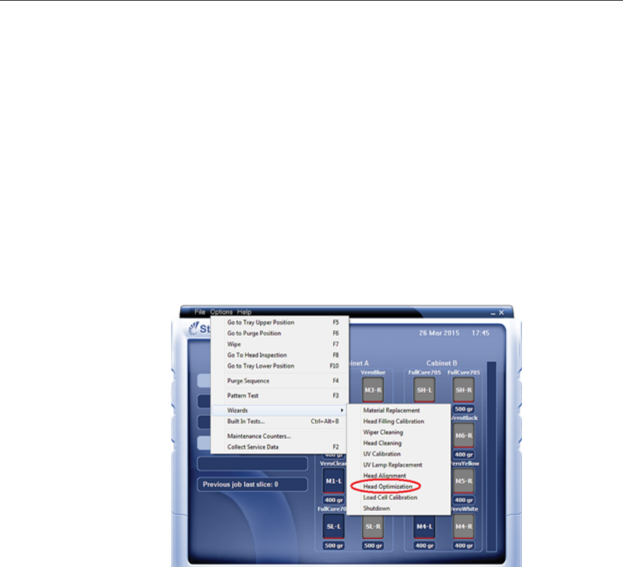
Operating & Maintaining the Stratasys P750K 3D Printer
6–36 DOC08010 Rev. A (DRAFT 1)
Note: To accurately test and calibrate print heads, they must be clean. If
necessary, run the Head Cleaning wizard before beginning this
procedure.
To test and calibrate the print heads:
1. Prepare—
•disposableȱcleaningȱglovesȱ(anyȱclean,ȱpowderȬfreeȱprotectiveȱ
gloves)
•pinkȱpaper
•theȱMissingȱNozzlesȱruler
•theȱscaleȱsuppliedȱforȱuseȱwithȱthisȱwizard
Note:Ensure that the scale is calibrated and charged before beginning
this procedure.
2. StartȱtheȱHeadȱOptimizationȱwizardȱfromȱtheȱOptionsȱmenu.
Figure 6-48: Starting the Head Optimization wizard
3. Inȱtheȱopeningȱwizardȱscreen,ȱclickȱNextȱtoȱbegin.
TheȱWizardȱConditionsȱscreenȱappears.
4. Readȱtheȱconditions,ȱselectȱIȱAgreeȱandȱclickȱNext.
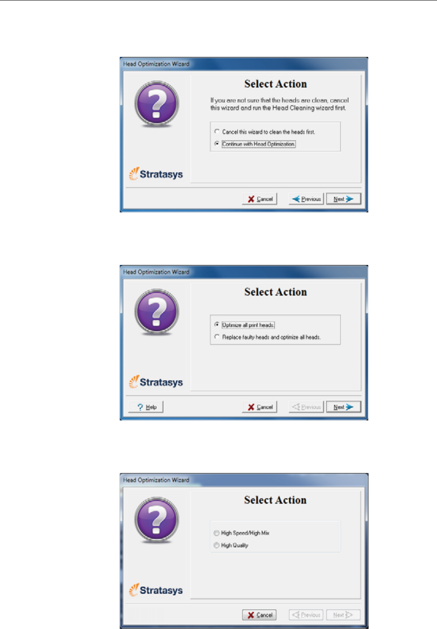
DOC08010 Rev. A (DRAFT 1) 6–37
Stratasys P750K User Guide
5. Inȱtheȱfollowingȱscreen,ȱselectȱContinue with Head optimizationȱifȱyouȱ
haveȱrecentlyȱcleanedȱtheȱprintȱheads.ȱOtherwise,ȱcancelȱtheȱwizardȱ
andȱrunȱtheȱHeadȱCleaningȱwizard.
Figure 6-49: Clean print heads screen
6. Inȱtheȱfollowingȱscreen,ȱmakeȱsureȱOptimizeȱallȱprintȱheadsȱisȱselectedȱ
andȱclickȱNext.
Figure 6-50: Procedure selection screen
7. Selectȱtheȱprintingȱmodeȱforȱwhichȱyouȱwantȱtoȱoptimizeȱtheȱprintȱ
headsȱandȱclickȱNext.
Figure 6-51: Printing mode selection
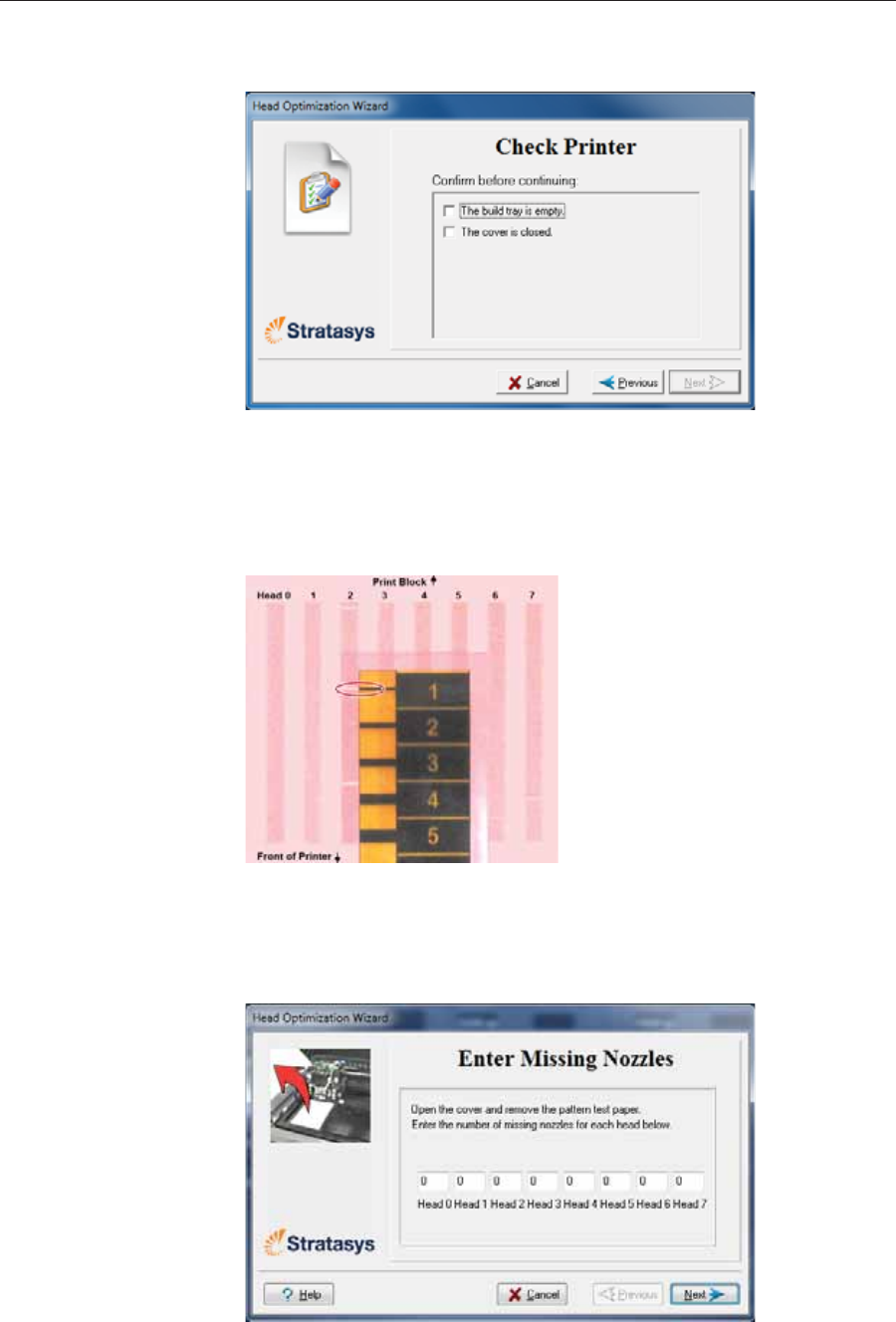
Operating & Maintaining the Stratasys P750K 3D Printer
6–38 DOC08010 Rev. A (DRAFT 1)
8. Whenȱtheȱfollowingȱscreenȱappears,ȱtapeȱaȱsheetȱofȱpinkȱpaperȱtoȱtheȱ
surfaceȱleftȱofȱtheȱbuildȱtray,ȱcloseȱtheȱcoverȱandȱclickȱNext.
Figure 6-52: Preparations confirmation
TheȱprinterȱprintsȱaȱframeȱonȱtheȱbuildȱtrayȱandȱthenȱprintsȱtheȱPatternȱ
Test.
9. WhenȱtheȱPatternȱTestȱisȱprinted,ȱcarefullyȱinspectȱit,ȱusingȱtheȱMissingȱ
NozzlesȱRulerȱtoȱseeȱifȱthereȱareȱmissingȱlines.
Figure 6-53: Inspecting the Pattern Test
Eachȱmissingȱlineȱrepresentsȱaȱfaultyȱnozzleȱinȱtheȱprintȱhead.
10. Inȱtheȱfollowingȱwizardȱscreen,ȱenterȱtheȱnumberȱofȱmissingȱnozzlesȱ
forȱeachȱprintȱheadȱandȱclickȱNext.
Figure 6-54: Enter Missing Nozzles screen
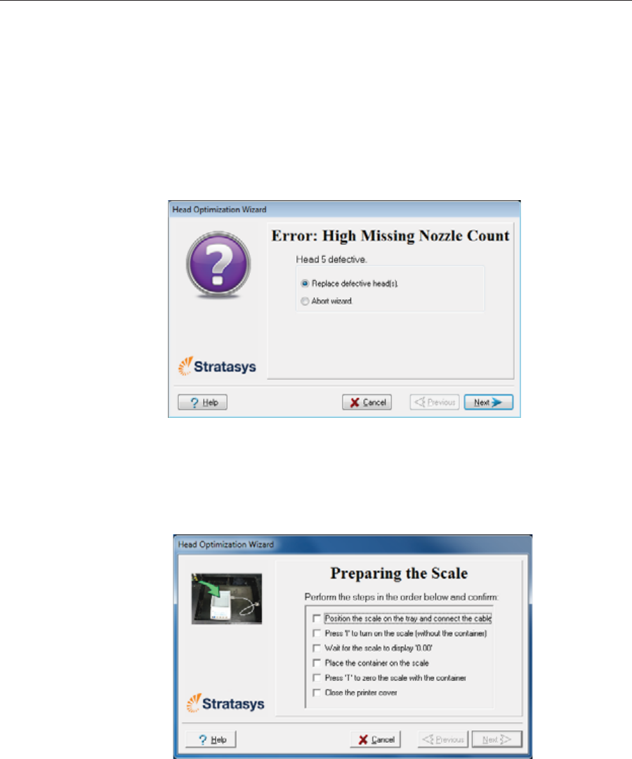
DOC08010 Rev. A (DRAFT 1) 6–39
Stratasys P750K User Guide
11. Theȱwizardȱcontinuesȱaccordingȱtheȱnumberȱofȱmissingȱnozzlesȱyouȱ
entered.ȱ
Ifȱthereȱareȱtooȱmanyȱmissingȱnozzlesȱforȱacceptableȱprinting,ȱtheȱ
wizardȱinstructsȱyouȱtoȱreplaceȱtheȱdefectiveȱprintȱhead(s).ȱYouȱcanȱ
doȱthisȱnow,ȱorȱabortȱtheȱwizard.
Ifȱyouȱareȱpreparedȱtoȱreplaceȱprintȱheadsȱnow,ȱtheȱwizardȱguidesȱ
youȱthroughȱtheȱprocedureȱwhenȱyouȱclickȱNext.ȱMakeȱsureȱyouȱ
haveȱreplacementȱheadsȱandȱtheȱrequiredȱtoolsȱ(seeȱpage 42).ȱ
Continueȱwithȱ“PreparingȱtheȱPrint Block”ȱonȱpage 44.
Figure 6-55: Head replacement due to missing nozzles
Ifȱtheȱnumberȱofȱmissingȱnozzlesȱinȱallȱprintȱheadsȱisȱacceptable,ȱtheȱ
wizardȱcontinuesȱwithȱtheȱheadȱoptimizationȱprocessȱ(below).
12. Setȱupȱtheȱscaleȱinȱtheȱprinterȱbyȱperformingȱtheȱstepsȱlistedȱinȱtheȱ
wizardȱscreen.
Figure 6-56: Setting up the Head Optimization scale
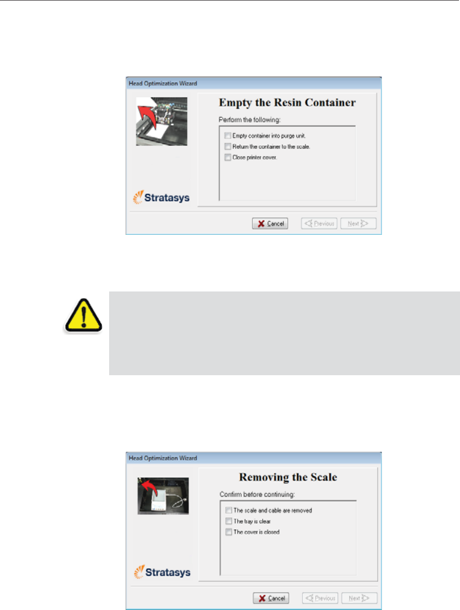
Operating & Maintaining the Stratasys P750K 3D Printer
6–40 DOC08010 Rev. A (DRAFT 1)
13. Afterȱconfirmingȱallȱofȱtheȱitemsȱlistedȱinȱtheȱwizardȱscreen,ȱclickȱNext.
Printingȱmaterialȱ(resin)ȱisȱjettedȱfromȱeachȱheadȱandȱitsȱweightȱisȱ
automaticallyȱrecorded.ȱThisȱprocessȱisȱrepeatedȱforȱeachȱprintingȱ
mode,ȱafterȱwhichȱtheȱfollowingȱscreenȱappears.
Figure 6-57: Emptying the Resin Container
14. Carefullyȱremoveȱtheȱresinȱcontainerȱfromȱtheȱscaleȱandȱemptyȱitȱintoȱ
theȱpurgeȱunitȱinȱtheȱprinter.ȱThenȱreturnȱtheȱcontainerȱtoȱtheȱscale.
15. CloseȱtheȱprinterȱandȱclickȱNext.
Theȱprinterȱcuresȱtheȱremainingȱresinȱinȱtheȱcontainer.
16. Whenȱtheȱfollowingȱscreenȱappears,ȱremoveȱtheȱscaleȱandȱcleanȱtheȱ
buildȱtray.ȱ
Figure 6-58: Removing the Scale confirmation screen
Theȱwizardȱusesȱtheȱdataȱcollectedȱtoȱanalyzeȱtheȱconditionȱofȱtheȱprintȱ
headsȱandȱoptimizeȱthemȱsoȱtheyȱprintȱmodelsȱwithȱaȱuniformȱlayerȱofȱ
material.ȱ
•Ifȱtheȱheadsȱareȱinȱsatisfactoryȱcondition,ȱtheȱfollowingȱwizardȱscreenȱ
appears.
CAUTION: The resin in the container is uncured.
¾To prevent contact with skin, wear neoprene or nitrile gloves.
¾Dispose of uncured resin in accordance with applicable regulations. By
emptying the container into the purge unit, the resin is stored in the
printer’s sealed waste container.
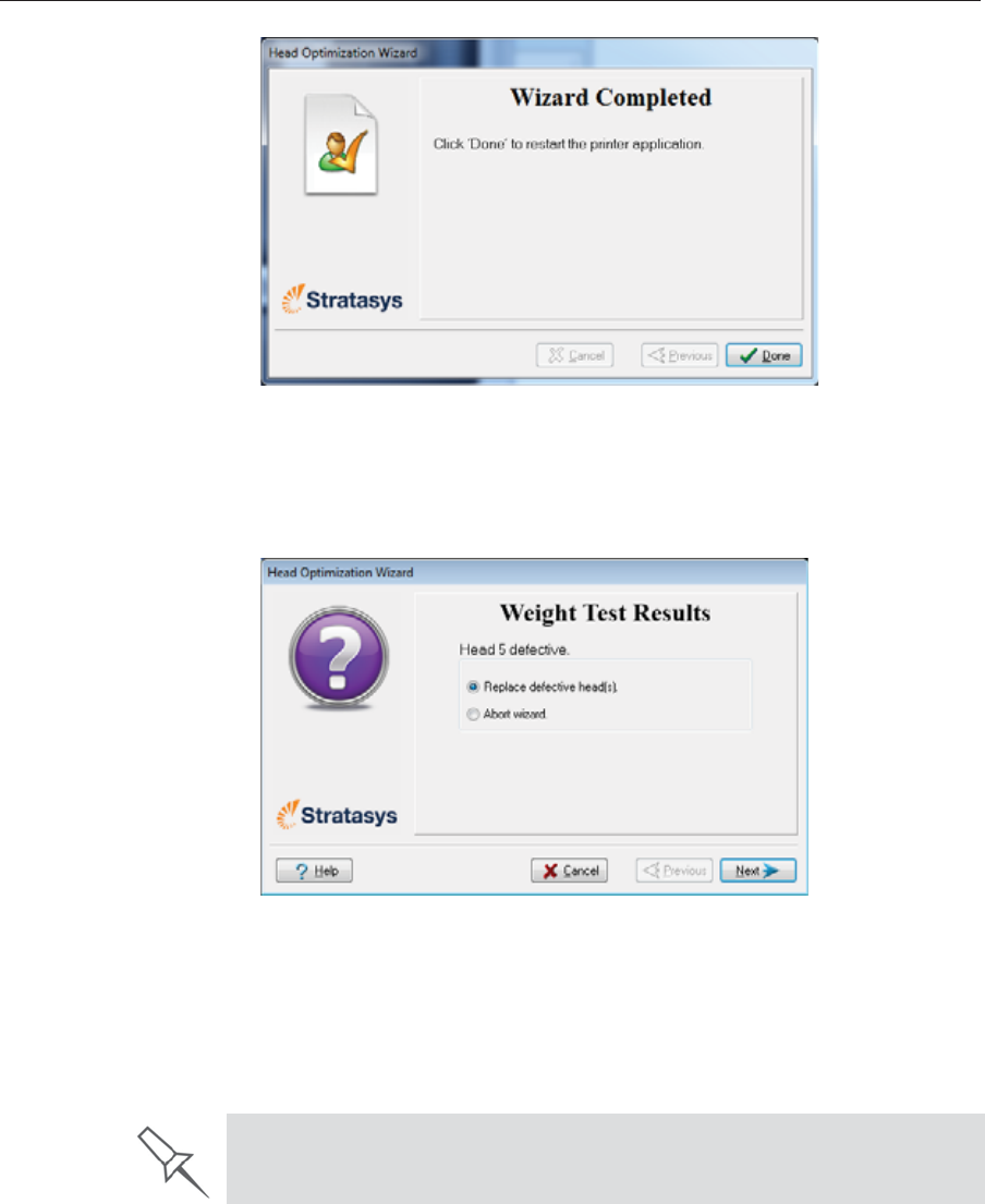
DOC08010 Rev. A (DRAFT 1) 6–41
Stratasys P750K User Guide
Figure 6-59: Final wizard screen, after optimizing print heads
•Ifȱtheȱwizardȱdeterminesȱthatȱaȱprintȱheadȱisȱfaulty—orȱthatȱitȱisȱ
negativelyȱaffectingȱmodelȱqualityȱwithȱtheȱcurrentȱheadȱ
configuration—youȱneedȱtoȱreplaceȱit.ȱIndicateȱwhetherȱorȱnotȱyouȱ
wantȱtoȱdoȱsoȱnow.
Figure 6-60: Defective print heads found
ChooseȱReplaceȱdefectiveȱhead(s)ȱifȱyouȱareȱpreparedȱtoȱreplaceȱtheȱ
printȱheadsȱnowȱ(seeȱbelow).ȱ
or—
ChooseȱAbortȱwizardȱifȱyouȱwantȱtoȱreplaceȱtheȱprintȱheadsȱatȱanotherȱ
time.
Replace print heads only after consulting with a Stratasys-authorized
customer-support engineer.

Operating & Maintaining the Stratasys P750K 3D Printer
6–42 DOC08010 Rev. A (DRAFT 1)
Toȱreplaceȱprintȱheads,ȱyouȱneedȱtheseȱtoolsȱandȱmaterials:
•replacementȱprintȱhead(s)
•isopropanolȱ(IPA—isopropylȱalcohol)ȱorȱethanolȱ(ethylȱalcohol)
•disposableȱcleaningȱglovesȱ(suppliedȱwithȱtheȱprintȱhead;ȱorȱuseȱ
anyȱclean,ȱpowderȬfreeȱprotectiveȱgloves)
•aȱsuppliedȱcleaningȱclothȱorȱequivalent
•aȱmirror
•aȱ5ȱmmȱflatȬheadȱscrewdriverȱorȱaȱ3ȱmmȱhexȱ(Allen®)ȱkey,ȱ
dependingȱonȱtheȱtypeȱofȱprintȱblock
•theȱscaleȱsuppliedȱforȱuseȱinȱtheȱHeadȱOptimizationȱwizardȱ(Weightȱ
Test)
•theȱMissingȱNozzlesȱruler
Ifȱyouȱareȱreplacingȱprintȱheadsȱnow,ȱtheȱwizardȱguidesȱyouȱthroughȱtheȱ
procedureȱwhenȱyouȱclickȱNext.ȱContinueȱwithȱ“PreparingȱtheȱPrint Block”ȱ
onȱpage 44.
Replacing
Print Heads Theȱconditionȱofȱtheȱprintȱheadsȱdirectlyȱaffectsȱtheȱqualityȱofȱprintedȱ
models.ȱYouȱmayȱneedȱtoȱreplaceȱaȱprintȱheadȱifȱoneȱorȱmoreȱofȱtheȱ
followingȱsymptomsȱoccurs:
•TheȱHeadȱOptimizationȱwizardȱdeterminesȱthatȱaȱprintȱheadȱisȱ
defective.ȱ(Seeȱ“Optimizingȱ(Calibrating)ȱPrintȱHeads”ȱonȱpage 35.)
•Thereȱareȱnoticeableȱgroovesȱinȱtheȱsurfaceȱofȱprintedȱmodels.
•Visualȱinspectionȱofȱtheȱheadȱrevealsȱthatȱitsȱsurfaceȱisȱdamaged—
peelingȱorȱbubblesȱinȱtheȱnozzleȱarea.
•Theȱprinterȱinterfaceȱdisplaysȱaȱwarningȱorȱmalfunctionȱmessageȱ
relatingȱtoȱaȱprintȱhead—
HeadȱHeaterȱtemperatureȱtimeout
HeadȱHeaterȱthermistorȱopen
HeadȱHeaterȱthermistorȱshort
Replace print heads only after consulting with an authorized customer-
support engineer.

DOC08010 Rev. A (DRAFT 1) 6–43
Stratasys P750K User Guide
TheȱHeadȱOptimizationȱwizardȱguidesȱyouȱthroughȱtheȱprocedureȱofȱ
replacingȱaȱprintȱheadȱandȱadjustsȱprinterȱcomponentsȱtoȱenableȱyouȱtoȱ
performȱit.ȱOnlyȱreplaceȱaȱprintȱheadȱwithȱtheȱaidȱofȱtheȱwizard.ȱTheȱentireȱ
procedureȱtakesȱaboutȱ45ȱminutes,ȱandȱconsistsȱofȱtheȱfollowingȱphases:ȱ
A. Identifyingȱtheȱhead(s)ȱneedingȱreplacement.ȱ
ThisȱisȱnormallyȱdoneȱbyȱtheȱHeadȱOptimizationȱwizard.ȱOtherwise,ȱ
evidenceȱofȱphysicalȱdamageȱtoȱtheȱheadȱsurfaceȱorȱaȱmalfunctionȱ
messageȱindicatesȱwhichȱheadȱneedsȱreplacing.
B. Preparingȱtheȱprintȱblockȱforȱheadȱreplacement.
Thisȱisȱdoneȱautomaticallyȱwhenȱyouȱrunȱtheȱwizard.
C. Removingȱtheȱdefectiveȱprintȱhead.
D. Installingȱaȱnewȱprintȱhead.
E. Optimizingȱtheȱprintȱheadsȱ(doneȱautomaticallyȱbyȱtheȱwizard).
F. Performingȱheadȱalignment.
To replace a print head:
1. Prepare—
•replacementȱprintȱhead(s)
•isopropanolȱ(IPA—isopropylȱalcohol)ȱorȱethanolȱ(ethylȱalcohol)
•disposableȱcleaningȱglovesȱ(suppliedȱwithȱtheȱprintȱhead;ȱorȱuseȱ
anyȱclean,ȱpowderȬfreeȱprotectiveȱgloves)
•aȱsuppliedȱcleaningȱclothȱorȱequivalent
•aȱmirror
•aȱ5ȱmmȱflatȬheadȱscrewdriverȱorȱaȱ3ȱmmȱhexȱ(Allen®)ȱkey,ȱ
dependingȱonȱtheȱtypeȱofȱprintȱblock
•theȱscaleȱsuppliedȱforȱuseȱinȱtheȱHeadȱOptimizationȱwizardȱ(Weightȱ
Test)
•theȱMissingȱNozzlesȱruler
Note: Make sure that you have these items and that the scale is calibrated
and charged before continuing.
2. StartȱtheȱHeadȱOptimizationȱwizardȱfromȱtheȱOptionsȱmenuȱ(seeȱ
figure 6Ȭ48ȱonȱpage 36).
3. Inȱtheȱopeningȱwizardȱscreen,ȱclickȱNextȱtoȱbegin.
TheȱWizardȱConditionsȱscreenȱappears.
4. Readȱtheȱconditions,ȱselectȱIȱAgreeȱandȱclickȱNext.
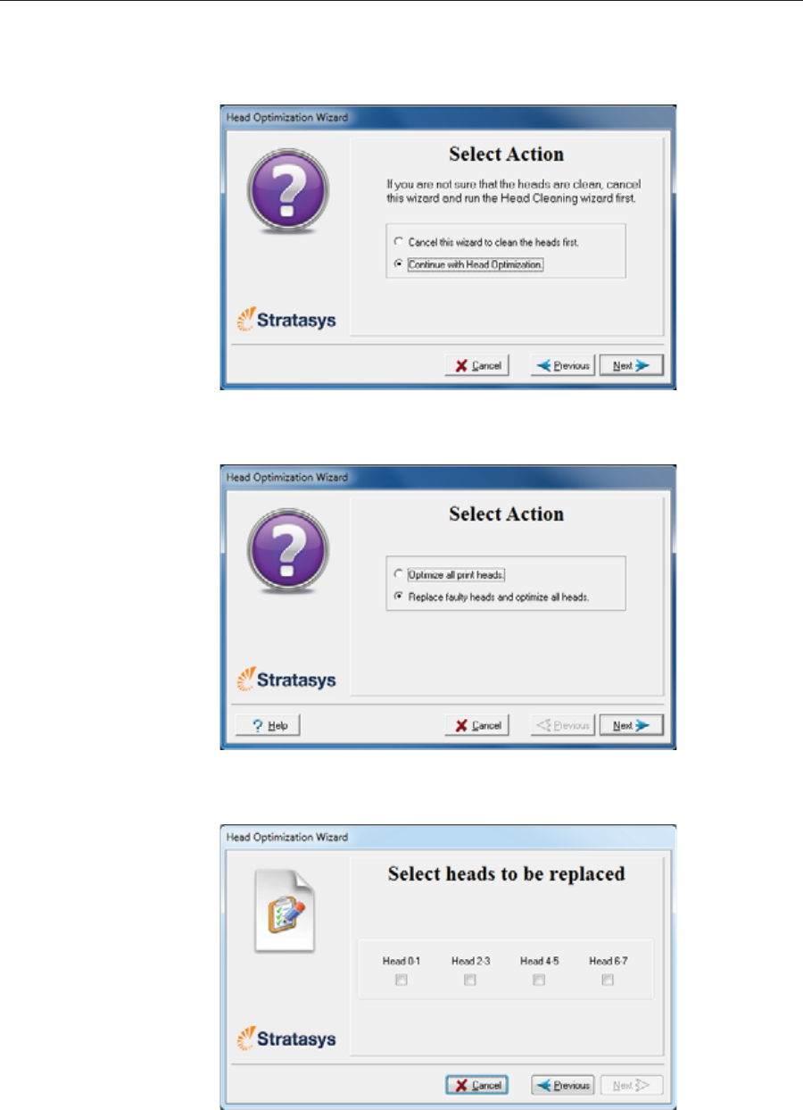
Operating & Maintaining the Stratasys P750K 3D Printer
6–44 DOC08010 Rev. A (DRAFT 1)
5. Inȱtheȱfollowingȱscreen,ȱselectȱContinue with Head optimizationȱifȱyouȱ
haveȱrecentlyȱcleanedȱtheȱprintȱheads.ȱOtherwise,ȱcancelȱtheȱwizardȱ
andȱrunȱtheȱHeadȱCleaningȱwizard.
Figure 6-61: Clean print heads screen
6. Inȱtheȱfollowingȱscreen,ȱselectȱReplaceȱfaultyȱheadsȱandȱclickȱNext.
Figure 6-62: Procedure selection screen
Preparing the
Print Block 7. Selectȱtheȱprintȱhead(s)ȱneedingȱreplacementȱandȱclickȱNext.
Figure 6-63: Head selection screen
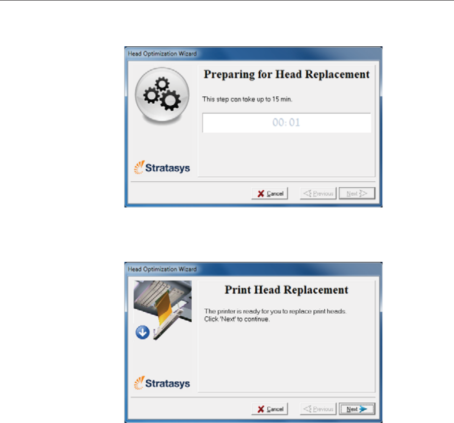
DOC08010 Rev. A (DRAFT 1) 6–45
Stratasys P750K User Guide
Theȱprinterȱheatsȱandȱemptiesȱtheȱprintȱblockȱandȱpreparesȱtheȱprinter.ȱ
(Thisȱcanȱtakeȱupȱtoȱ15ȱminutes.)
Figure 6-64: Printer preparation progress screen
8. Theȱfollowingȱscreenȱappearsȱwhenȱtheȱprinterȱisȱreadyȱforȱyouȱtoȱ
replaceȱprintȱheads.
Figure 6-65: Printer ready for head replacement
9. Putȱonȱtheȱprotectiveȱglovesȱandȱopenȱtheȱprinterȱcover.
Note: The printer disconnects power to the heads for your safety.
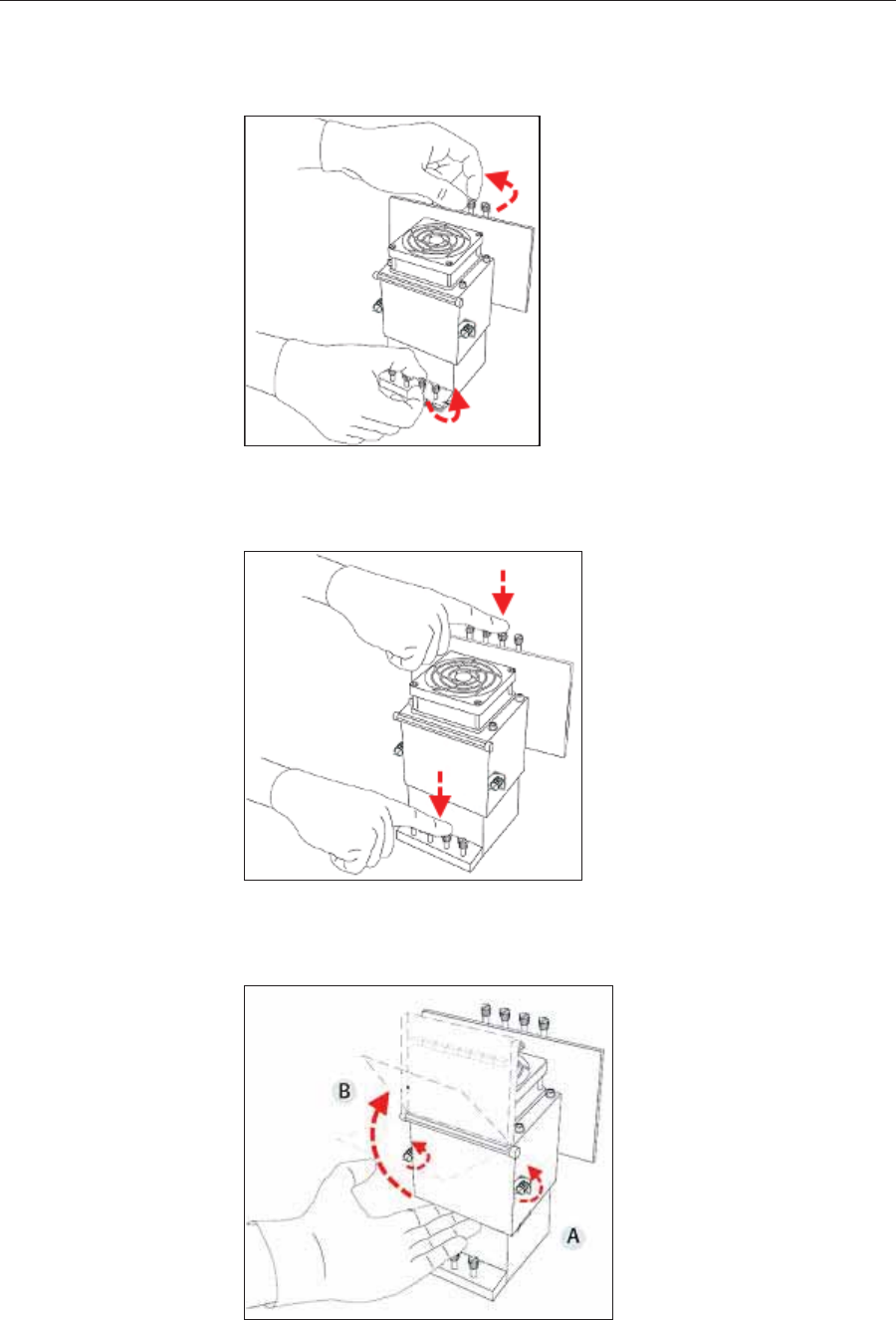
Operating & Maintaining the Stratasys P750K 3D Printer
6–46 DOC08010 Rev. A (DRAFT 1)
Removing the
Defective Head 10. Onȱtheȱprintȱblock,ȱreleaseȱtheȱupperȱandȱlowerȱscrewsȱthatȱsecureȱtheȱ
printȱheadȱinȱtheȱblock.ȱ(Ifȱnecessary,ȱyouȱmayȱuseȱaȱscrewdriverȱtoȱ
loosenȱtheȱscrews.)
Figure 6-66: Releasing the locking screws
11. Pressȱdownȱonȱtheȱupperȱandȱlowerȱlockingȱscrewsȱtoȱreleaseȱtheȱprintȱ
head.
Figure 6-67: Releasing the print head
12. Loosenȱtheȱscrewsȱonȱtheȱdoorȱofȱtheȱcompartmentȱprotectingȱtheȱ
printȬheadȱdriverȱcardsȱ(A),ȱthenȱpullȱandȱliftȱupȱtheȱdoorȱ(B).
Figure 6-68: Opening the print-head compartment
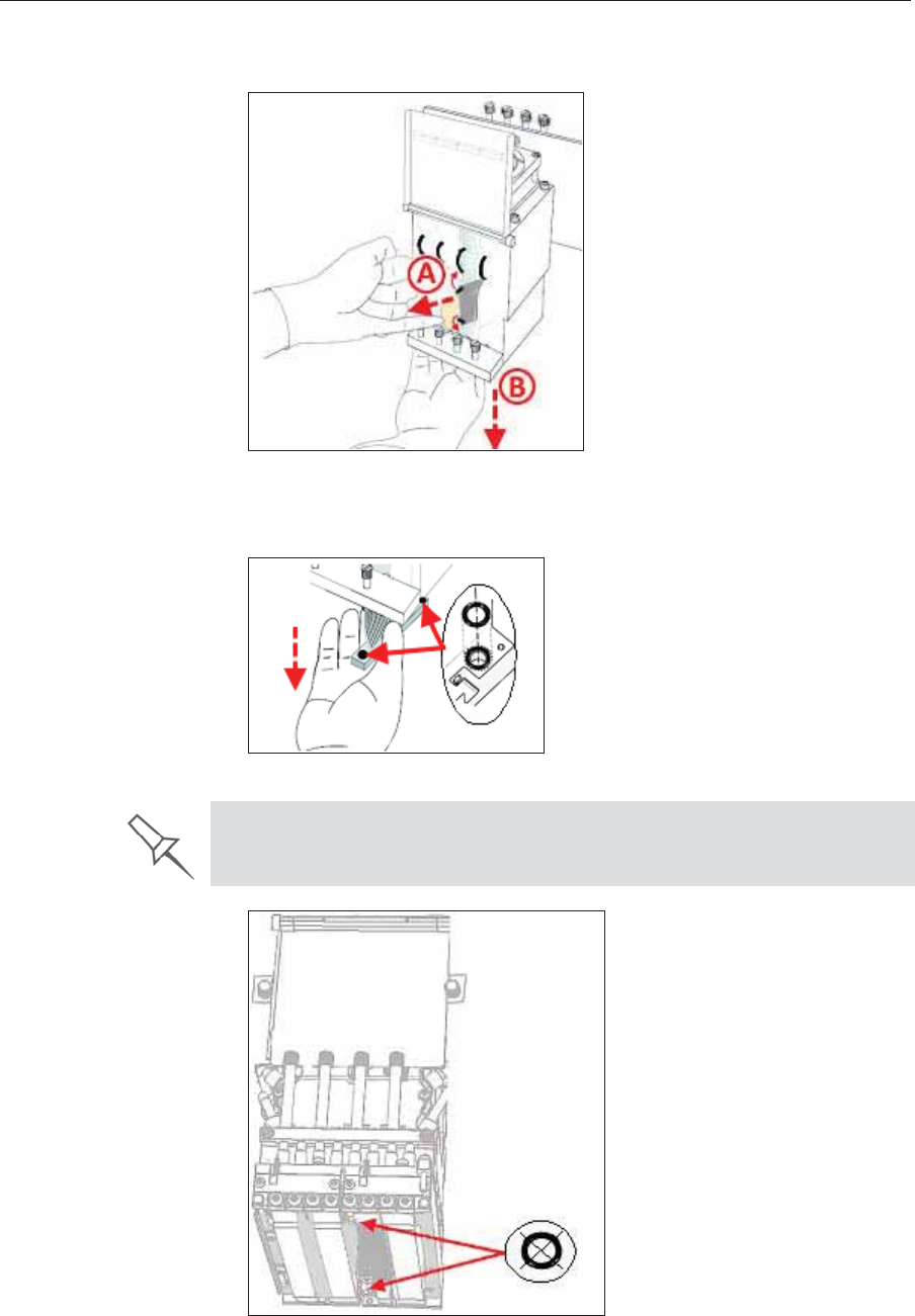
DOC08010 Rev. A (DRAFT 1) 6–47
Stratasys P750K User Guide
13. PullȱtheȱprintȬheadȱdriverȱcardȱoutȱofȱitsȱsocketȱsoȱthatȱtheȱheadȱisȱfreeȱ
(A)ȱandȱremoveȱitȱfromȱtheȱbottomȱofȱtheȱprintȱblockȱ(B).
Figure 6-69: Releasing the print-head driver card to remove the head
14. Makeȱsureȱthatȱalongȱwithȱtheȱhead,ȱyouȱremoveȱtheȱtwoȱrubberȱOȬringȱ
seals.
Figure 6-70: O-ring seals on the print head
Figure 6-71: Making sure the O-rings are not stuck to the print block
Important: If the seals are not removed with the head, they are probably
stuck to the print block housing. If so, remove them.
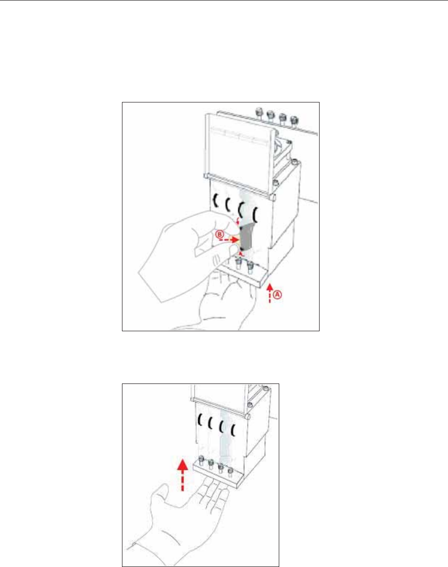
Operating & Maintaining the Stratasys P750K 3D Printer
6–48 DOC08010 Rev. A (DRAFT 1)
Installing the
New Head 15. InspectȱtheȱreplacementȱheadȱandȱmakeȱsureȱthatȱtheȱOȬringȱsealsȱareȱ
inȱplaceȱ(seeȱfigure 6Ȭ70).
16. Gentlyȱinsertȱtheȱreplacementȱheadȱintoȱtheȱvacantȱslotȱinȱtheȱprintȱ
blockȱandȱpushȱtheȱprintȬheadȱdriverȱcardȱintoȱitsȱsocket.
Note: Make sure to insert the head with the driver card facing its socket, in
the rear of the print block.
Figure 6-72: Inserting the print-head driver card into its socket
17. Pushȱtheȱheadȱupȱuntilȱyouȱhearȱitȱclickȱintoȱplace,ȱinȱbothȱfrontȱandȱ
rearȱholders.
Figure 6-73: Clicking the head into place in the print block
18. Lowerȱtheȱdoorȱofȱtheȱprintȱheadȱcompartmentȱandȱtightenȱtheȱscrewsȱ
toȱlockȱitȱinȱplace.
19. Tightenȱtheȱupperȱandȱlowerȱscrewsȱthatȱsecureȱtheȱprintȱheadȱinȱtheȱ
printȱblockȱ(seeȱfigure 6Ȭ66ȱonȱpage 46).
Note: Hand-tighten these screws. Do not use a screwdriver.
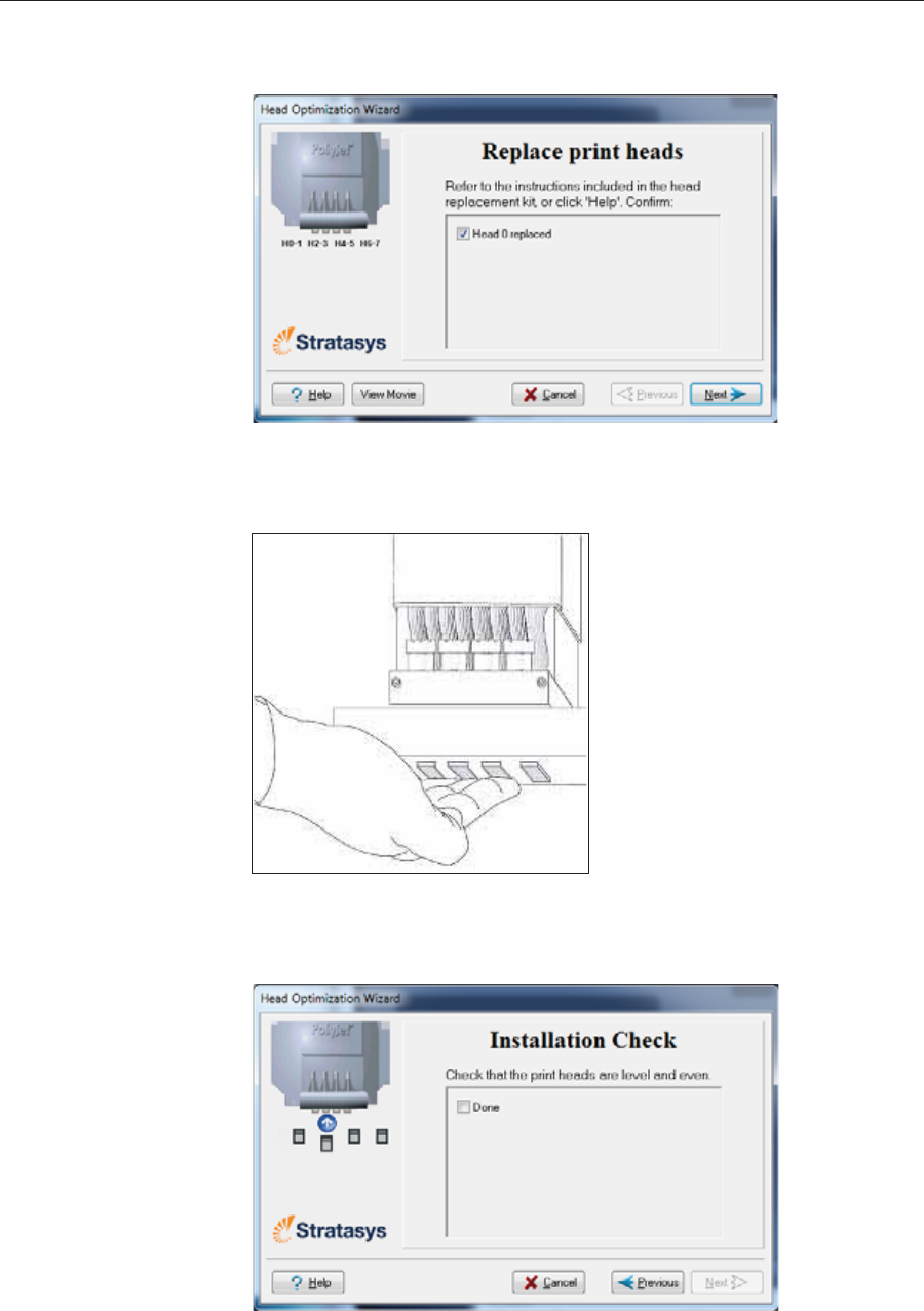
DOC08010 Rev. A (DRAFT 1) 6–49
Stratasys P750K User Guide
20. InȱtheȱReplaceȱprintȱheadsȱscreen,ȱselectȱtheȱcheckȱboxȱtoȱconfirmȱthatȱ
youȱhaveȱreplacedȱtheȱhead(s)ȱandȱclickȱNext.
Figure 6-74: Head replacement confirmation
21. Withȱyourȱfingers,ȱmakeȱsureȱthatȱtheȱnewȱheadȱisȱlevelȱandȱevenȱwithȱ
theȱotherȱheads.
Figure 6-75: Checking the level of the new head
22. Confirmȱthatȱtheȱheadsȱareȱlevelȱandȱevenȱbyȱselectingȱtheȱcheckȱboxȱinȱ
theȱfollowingȱwizardȱscreenȱandȱclickȱNext.
Figure 6-76: Installation-check screen
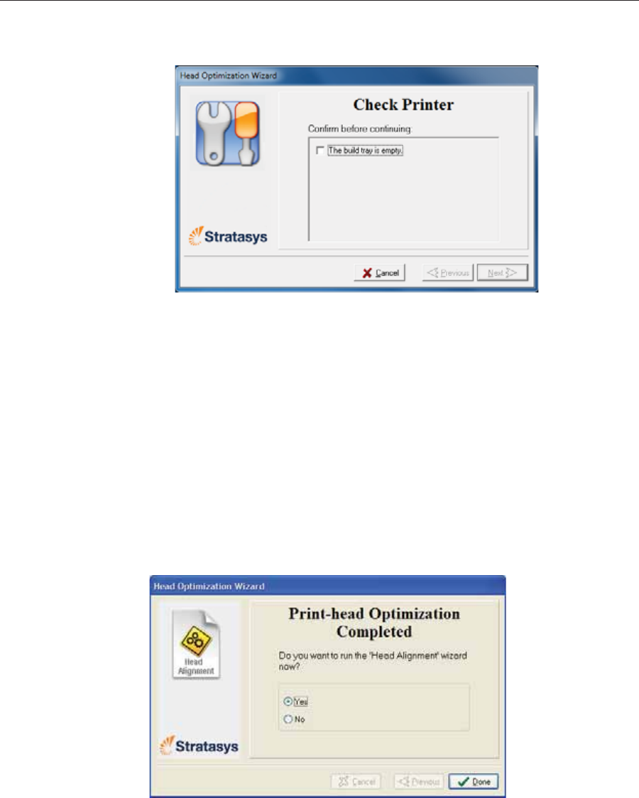
Operating & Maintaining the Stratasys P750K 3D Printer
6–50 DOC08010 Rev. A (DRAFT 1)
23. Inȱtheȱnextȱwizardȱscreen,ȱconfirmȱthatȱyouȱhaveȱremovedȱallȱtoolsȱandȱ
objectsȱfromȱtheȱprinter.
Figure 6-77: Cleared-tray confirmation screen
24. Closeȱtheȱprinterȱcover.
Theȱwizardȱcontinuesȱbyȱheatingȱtheȱheads,ȱthenȱfillingȱandȱpurgingȱthem.ȱ
Ifȱthereȱareȱnoȱinstallationȱproblems,ȱtheȱoptimizationȱprocedureȱbegins,ȱtoȱ
calibrateȱtheȱprintȱheadsȱtoȱtheȱbestȱworkingȱconfiguration—seeȱ
“Optimizingȱ(Calibrating)ȱPrintȱHeads”ȱonȱpage 6Ȭ35.
Ifȱinstallationȱproblemsȱareȱdetected,ȱtheȱwizardȱalertsȱyouȱandȱinstructsȱ
youȱhowȱtoȱcontinueȱ(seeȱ“InstallationȱProblems,”ȱnext).
Afterȱreplacingȱprintȱheads,ȱyouȱshouldȱcheckȱtheȱheadȱalignmentȱbeforeȱ
usingȱtheȱprinterȱtoȱproduceȱmodels.ȱInȱtheȱfinalȱwizardȱscreen...
¾SelectȱYesȱandȱclickȱDoneȱtoȱopenȱtheȱHeadȱAlignmentȱwizardȱ(seeȱ
“AligningȱtheȱPrintȱHeads”ȱonȱpage 32).ȱ
¾SelectȱNoȱandȱclickȱDoneȱtoȱalignȱtheȱheadsȱatȱanotherȱtime.
Figure 6-78: Final wizard Screen
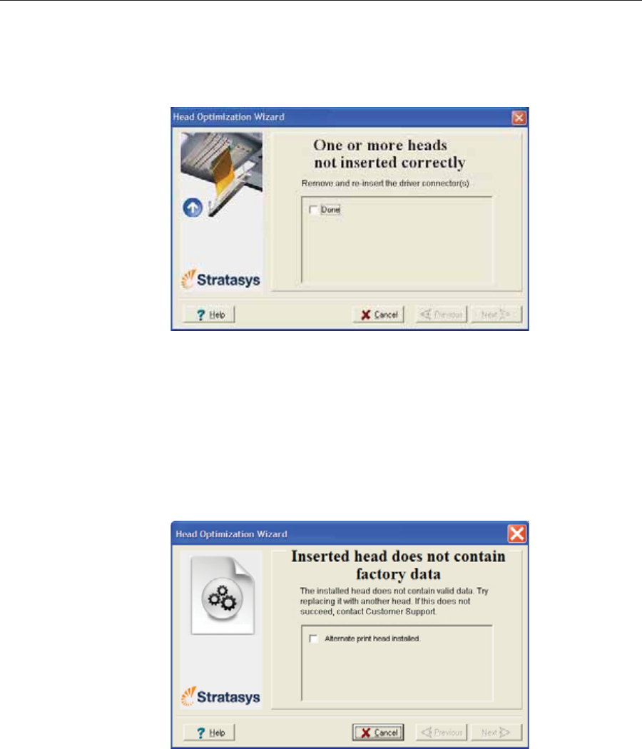
DOC08010 Rev. A (DRAFT 1) 6–51
Stratasys P750K User Guide
Installation
Problems Ifȱtheȱprinterȱdetectsȱthatȱthereȱisȱaȱproblemȱafterȱyouȱinstallȱprintȱheads,ȱ
relevantȱwarningȱscreensȱappear.
•Ifȱtheȱprinterȱsoftwareȱdoesȱnotȱdetectȱtheȱreplacedȱhead,ȱtheȱfollowingȱ
warningȱscreenȱappears.ȱ
Figure 6-79: Incorrect-installation screen
Ifȱthisȱhappens:ȱ
a. Openȱtheȱprintȱheadȱcompartmentȱ(seeȱfigure 6Ȭ68ȱonȱpage 46).
b. ReȬinsertȱtheȱprintȬheadȱdriverȱcardȱintoȱitsȱsocketȱ(seeȱfigure 6Ȭ72ȱ
onȱpage 48).
c. Inȱtheȱwizardȱscreen,ȱselectȱtheȱcheckȱboxȱtoȱconfirmȱthatȱyouȱhaveȱ
reȬinsertedȱtheȱcardȱandȱclickȱNext.
•IfȱtheȱreplacementȱheadȱwasȱnotȱfactoryȬcalibrated,ȱtheȱfollowingȱ
warningȱscreenȱappears.ȱ
Figure 6-80: Invalid-data warning screen
Ifȱthisȱhappens:ȱ
a. Removeȱtheȱheadȱandȱreplaceȱitȱwithȱanotherȱoneȱ(startingȱwithȱ
step 10ȱonȱpage 46).
b. Inȱtheȱwizardȱscreen,ȱselectȱtheȱcheckȱboxȱtoȱconfirmȱthatȱyouȱhaveȱ
installedȱanotherȱprintȱheadȱandȱclickȱNext.
c. ContactȱyourȱauthorizedȱCustomerȱSupportȱcenterȱaboutȱtheȱ
unformattedȱhead.
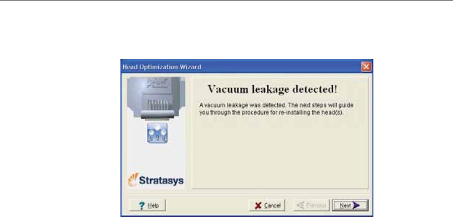
Operating & Maintaining the Stratasys P750K 3D Printer
6–52 DOC08010 Rev. A (DRAFT 1)
•Ifȱtheȱvacuumȱtestȱisȱnotȱsuccessful,ȱtheȱreplacementȱheadȱwasȱnotȱ
sealedȱproperlyȱduringȱinstallation,ȱandȱtheȱfollowingȱwarningȱscreenȱ
appears.
Figure 6-81: Vacuum-leakage warning screen
Ifȱthisȱhappens:ȱ
a. ClickȱNext.
b. FollowȱtheȱinstructionsȱonȱtheȱwizardȱscreensȱtoȱreȬinstallȱtheȱhead.
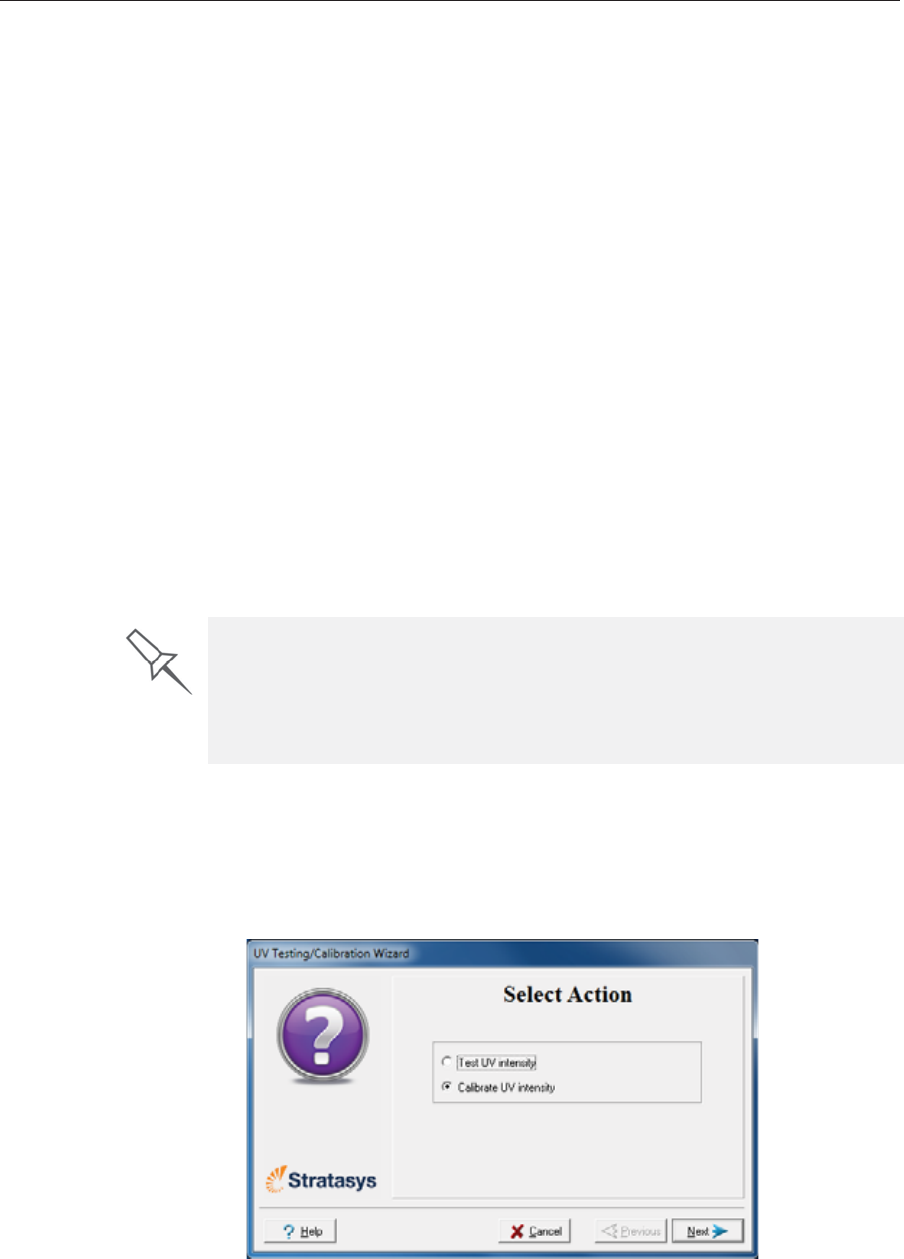
DOC08010 Rev. A (DRAFT 1) 6–53
Stratasys P750K User Guide
Testing and
Calibrating the
UV Lamps
TheȱeffectiveȱUVȱradiationȱfromȱtheȱlampsȱusedȱforȱcuringȱmodelsȱcanȱ
changeȱoverȱtime.ȱToȱensureȱoptimumȱcuringȱofȱmodelsȱduringȱprinting,ȱaȱ
popȬupȱmessageȱremindsȱyouȱtoȱtestȱtheȱlampsȱandȱcalibrateȱtheirȱeffectiveȱ
UVȱradiationȱafterȱeveryȱ300ȱhoursȱofȱprinting.ȱYouȱdoȱthisȱbyȱrunningȱtheȱ
UVȱCalibrationȱWizard.
ToȱmeasureȱtheȱUVȱradiation,ȱyouȱneed:
•StratasysȱTOLȬ03005ȬSȱ(UVȱsensorȱandȱcable,ȱsuppliedȱwithȱtheȱprinter)
or—
•aȱstandȬaloneȱUVȱradiationȱmeter,ȱapprovedȱforȱuseȱwithȱtheȱprinter
Theȱwizardȱcomparesȱtheȱmeasuredȱradiationȱtoȱtheȱrecommendedȱ
radiationȱlevelȱforȱeachȱofȱtheȱlamps,ȱatȱeachȱprintingȱmode—HighȱSpeed,ȱȱ
HighȱQualityȱandȱDigitalȱMaterial.
Whenȱcalibratingȱtheȱlamps,ȱtheȱwizardȱattemptsȱtoȱadjustȱtheȱradiationȱ
level,ȱifȱnecessary.
•Ifȱtheȱreadingȱisȱwithinȱtheȱacceptableȱrange,ȱtheȱwizardȱcontinuesȱtoȱ
theȱnextȱphase.ȱ
•Ifȱfurtherȱadjustmentȱisȱnecessary,ȱtheȱcurrentȱphaseȱisȱrepeated.ȱ
•IfȱtheȱUVȱradiationȱisȱtooȱlowȱtoȱbeȱproperlyȱadjusted,ȱtheȱwizardȱ
continuesȱtoȱtheȱnextȱphase,ȱbutȱtheȱfinalȱwizardȱscreenȱindicatesȱthatȱ
theȱlamp’sȱradiationȱforȱtheȱprintingȱmodeȱisȱunacceptable.
To test and calibrate UV lamp radiation:
1. StartȱtheȱUVȱCalibrationȱWizardȱfromȱtheȱOptionsȱmenuȱ(seeȱfigure 6Ȭ22ȱ
onȱpage 6Ȭ23).
2. Inȱtheȱfollowingȱscreen,ȱselectȱCalibrate UV Intensity toȱadjustȱtheȱlamp’sȱ
radiationȱlevelȱtoȱtheȱacceptableȱrange.ȱ
Figure 6-82: UV Test/Calibration selection
Before testing and calibrating the UV lamps:
¾Make sure the glass lens on each of the UV lamps is clean. For easy
access, run the Head Cleaning Wizard, and use the special cleaning pad
supplied.
¾Make sure that the glass over the UV radiation sensor is clean.
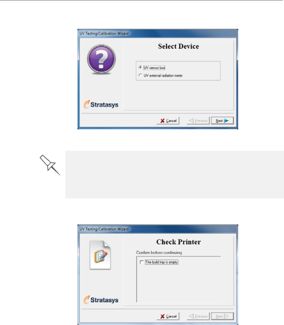
Operating & Maintaining the Stratasys P750K 3D Printer
6–54 DOC08010 Rev. A (DRAFT 1)
3. Inȱtheȱfollowingȱscreen,ȱselectȱtheȱUVȱsensorȱandȱmeasuringȱdeviceȱtoȱ
beȱused.
Figure 6-83: UV device selection
4. Makeȱsureȱthatȱtheȱbuildȱtrayȱisȱclearȱ(empty),ȱconfirmȱthisȱinȱtheȱ
wizardȱscreenȱandȱclickȱNext.
Figure 6-84: Printer preparation
¾WhenȱusingȱtheȱStratasysȱUVȱsensorȱ(TOLȬ03005ȬS),ȱcontinueȱwithȱ
“UVȱsensorȱconnectedȱtoȱprinter,”ȱbelow.
¾WhenȱusingȱaȱstandȬaloneȱradiationȱmeter,ȱcontinueȱwithȱ“ExternalȱUVȱ
meter”ȱonȱpage 57.
UV Measuring Device
When you use the Stratasys UV sensor (TOL-03005-S), you connect it to the
printer. The wizard automatically measures and calibrates the UV radiation.
If you use a stand-alone UV radiation meter, you need to manually enter the
readings from the meter in the wizard screens.
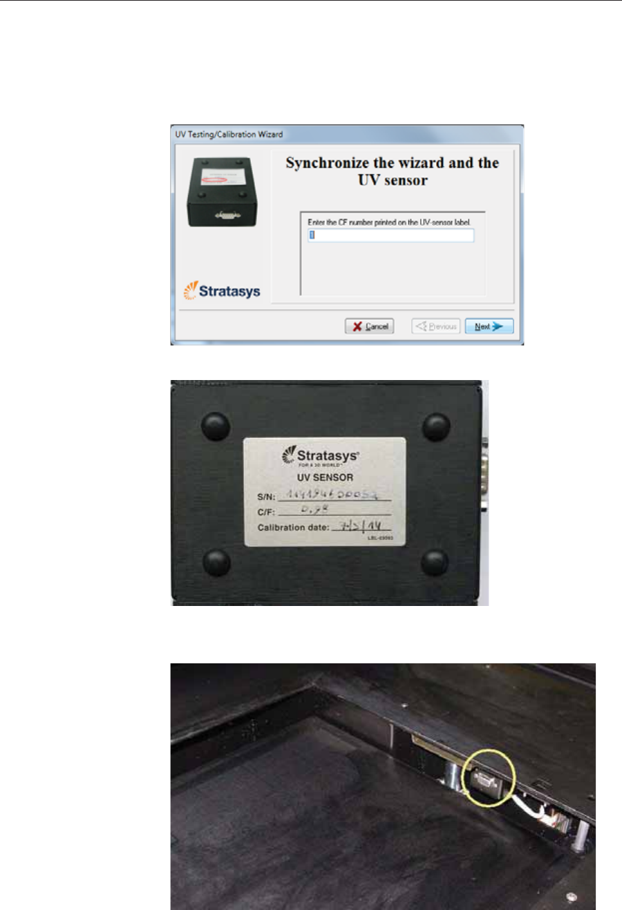
DOC08010 Rev. A (DRAFT 1) 6–55
Stratasys P750K User Guide
The following steps apply when using the Stratasys UV sensor that you
connect to the printer (TOL-03005-S). They do not apply when using a
stand-alone UV radiation measuring device.
UV sensor
connected to printer 1. AdjustȱtheȱwizardȱforȱtheȱsensitivityȱofȱtheȱUVȱsensorȱbyȱenteringȱtheȱ
CFȱnumberȱthatȱappearsȱonȱtheȱsensor’sȱlabel.
Figure 6-85: UV sensor synchronization
Figure 6-86: Label on the bottom of the UV sensor
TheȱbuildȱtrayȱlowersȱsoȱyouȱcanȱconnectȱtheȱUVȱsensor.
Figure 6-87: UV sensor connector
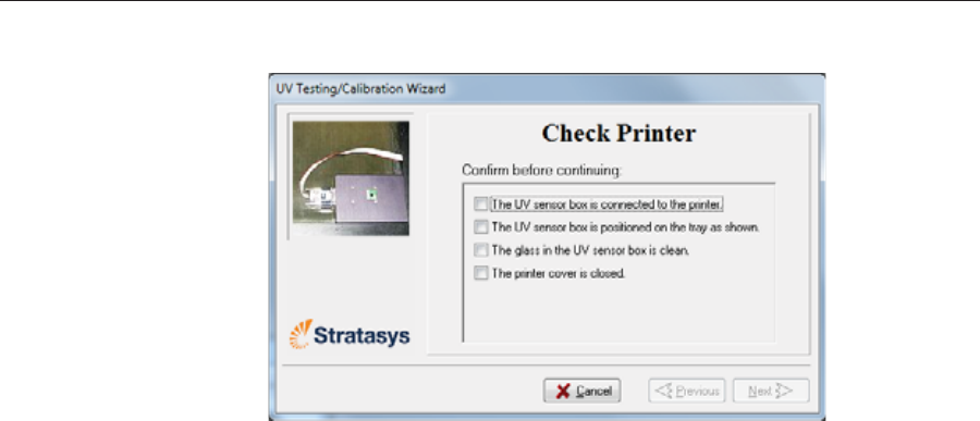
Operating & Maintaining the Stratasys P750K 3D Printer
6–56 DOC08010 Rev. A (DRAFT 1)
2. ConnectȱtheȱUVȱsensorȱcableȱtoȱtheȱconnectorȱinȱtheȱprinter.
Figure 6-88: Sensor preparation
3. ConfirmȱtheȱitemsȱlistedȱinȱtheȱwizardȱscreenȱandȱclickȱNext.
Continue with “UV measurement” on page 58.
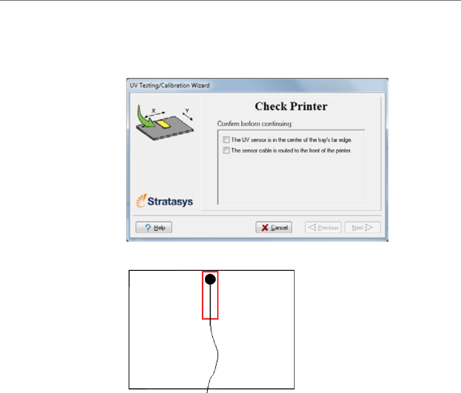
DOC08010 Rev. A (DRAFT 1) 6–57
Stratasys P750K User Guide
External UV meter The following steps apply when using a stand-alone UV meter. They do
not apply when using the Stratasys UV sensor connected to the printer.
1. Whenȱtheȱfollowingȱscreenȱappears,ȱopenȱtheȱprinterȱandȱplaceȱtheȱUVȱ
sensorȱatȱtheȱrearȱedgeȱofȱtheȱtray,ȱinȱtheȱcenter.
Figure 6-89: Sensor placement screen
Figure 6-90: Correct UV-sensor placement
2. Leadȱtheȱcableȱoutȱofȱtheȱprinterȱsoȱthatȱyouȱcanȱcloseȱtheȱprinter,ȱandȱ
makeȱsureȱthatȱtheȱcableȱwillȱnotȱinterfereȱwithȱtheȱmovingȱprintȱblock.
3. Closeȱtheȱprinter,ȱwhileȱcheckingȱthatȱtheȱsensorȱdoesȱnotȱmoveȱoutȱofȱ
position.
4. SetȱtheȱUVȱmeterȱtoȱmeasureȱmJ/cm2.
5. Setȱtheȱrangeȱonȱtheȱmeterȱtoȱ2,000.
6. ConnectȱtheȱcableȱfromȱtheȱsensorȱtoȱtheȱUVȱmeter.ȱ
7. TurnȱonȱtheȱUVȱmeter,ȱandȱwaitȱuntilȱ“0ȱ0ȱ0.0”ȱappearsȱonȱtheȱdisplay.
8. Inȱtheȱwizardȱscreen,ȱconfirmȱthatȱtheȱsensorȱisȱpositionedȱcorrectly,ȱ
andȱclickȱNext.
Continue with “UV measurement” on page 58.
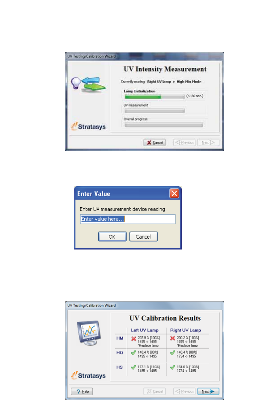
Operating & Maintaining the Stratasys P750K 3D Printer
6–58 DOC08010 Rev. A (DRAFT 1)
UV measurement TheȱUVȱlampsȱpowerȱupȱandȱstabilize.ȱ(Thisȱtakesȱseveralȱminutes.)ȱThen,ȱ
theȱprintȱblockȱpassesȱoverȱtheȱsensorȱandȱtheȱwizardȱcomparesȱtheȱ
measuredȱradiationȱtoȱtheȱrecommendedȱlevelȱforȱeachȱUVȱlampȱandȱ
printingȱmode.ȱDuringȱthisȱprocess,ȱwhichȱtakesȱ20–40ȱminutes,ȱyouȱneedȱ
toȱmonitorȱtheȱprogressȱasȱdisplayedȱinȱtheȱwizardȱscreen.
Figure 6-91: UV measurement progress
¾WhenȱusingȱaȱstandȬaloneȱradiationȱmeter,ȱresetȱtheȱmeterȱandȱenterȱtheȱ
readingȱ(measurement)ȱwhenȱyouȱareȱpromptedȱtoȱdoȱso.
Figure 6-92: UV measurement dialog box
IfȱtheȱUVȱlevelȱmeasuredȱisȱnotȱacceptable,ȱtheȱwizardȱcalibratesȱtheȱUVȱ
lampȱbyȱadjustingȱtheȱcurrentȱsuppliedȱtoȱit,ȱandȱthenȱtestsȱitȱagain.
WhenȱallȱUVȱtestsȱhaveȱfinished,ȱtheȱresultsȱareȱdisplayed,ȱshowingȱtheȱ
conditionȱofȱtheȱlampsȱafterȱcalibrationȱ(seeȱfigure 6Ȭ93).
Figure 6-93: Results and condition of UV lamps after calibration
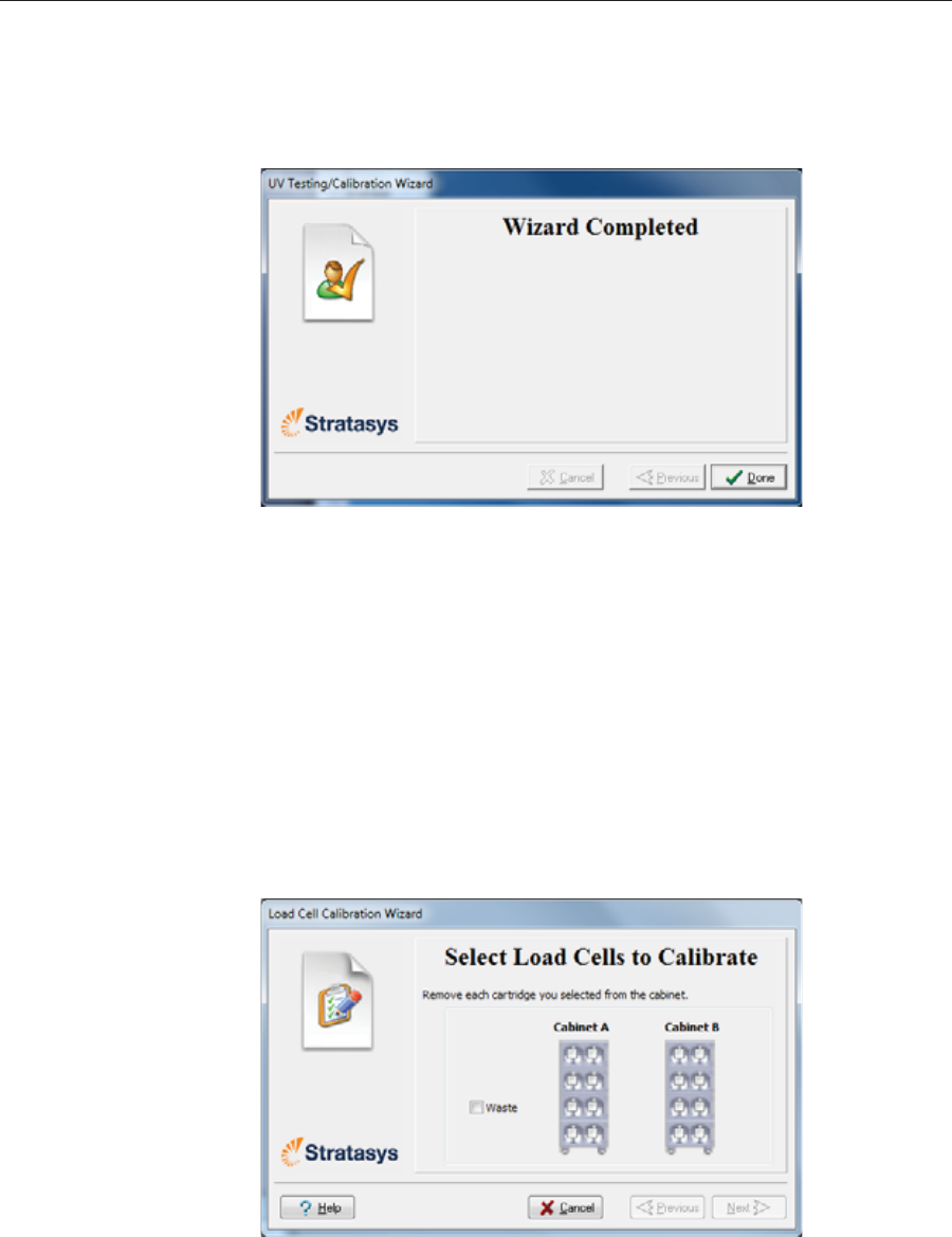
DOC08010 Rev. A (DRAFT 1) 6–59
Stratasys P750K User Guide
After examining the UV calibration results:
1. ClickȱNext.
2. RemoveȱtheȱUVȱsensorȱandȱcloseȱtheȱprinterȱcover.ȱAfterȱconfirmingȱ
theȱitemsȱlistedȱinȱtheȱwizardȱscreen,ȱclickȱNext.
Figure 6-94: Final UV Calibration Wizard screen
Calibrating the
Load Cells Loadȱcellsȱareȱsensorsȱthatȱmeasureȱtheȱweightȱofȱtheȱmaterialȱcartridgesȱ
andȱtheȱwasteȱcontainerȱinȱtheȱprinter.ȱItȱisȱimportantȱthatȱyouȱperiodicallyȱ
checkȱthatȱtheȱweightȱmeasurementsȱareȱaccurate,ȱbothȱforȱconvenienceȱandȱ
toȱpreventȱunnecessaryȱwasteȱofȱprintingȱmaterials.ȱItȱisȱrecommendedȱthatȱ
youȱcalibrateȱtheȱloadȱcellsȱonceȱaȱmonth.
To calibrate load cells:
1. StartȱtheȱLoadȱCellȱCalibrationȱwizardȱfromȱtheȱOptionsȱmenuȱ(seeȱ
figure 6Ȭ8ȱonȱpage 11).ȱ
2. Inȱtheȱfollowingȱscreen,ȱselectȱoneȱorȱmoreȱloadȱcellsȱthatȱyouȱwantȱtoȱ
calibrate.ȱ
Figure 6-95: Load cell selection
3. Removeȱeachȱselectedȱcartridgeȱfromȱtheȱmaterialsȱcart,ȱandȱclickȱNext.
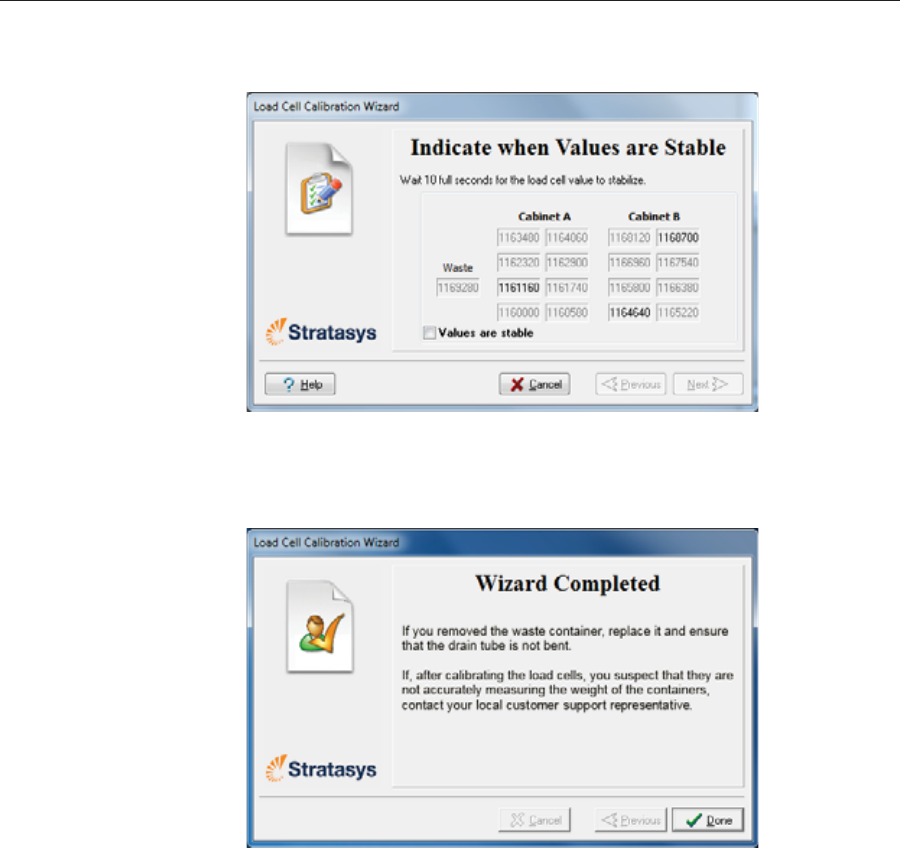
Operating & Maintaining the Stratasys P750K 3D Printer
6–60 DOC08010 Rev. A (DRAFT 1)
4. Inȱtheȱnextȱwizardȱscreen,ȱobserveȱtheȱnumbersȱandȱwaitȱuntilȱtheȱlevelȱ
isȱrelativelyȱstable—twoȱunitsȱaboveȱorȱbelowȱtheȱaverageȱlevelȱshown.
Figure 6-96: Level stabilization
5. Selectȱtheȱcheckȱbox,ȱandȱclickȱNext.
6. ClickȱDoneȱinȱtheȱfinalȱwizardȱscreen.
Figure 6-97: Final wizard screen
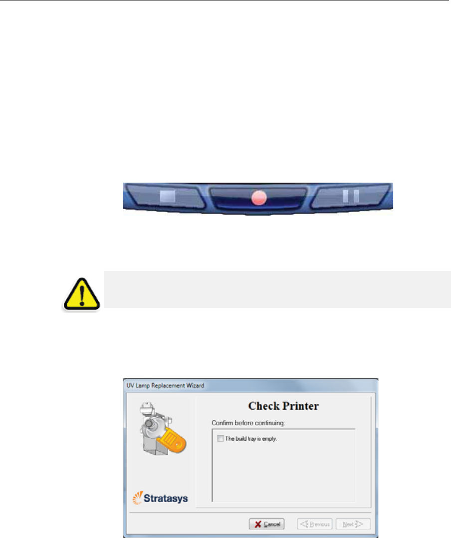
DOC08010 Rev. A (DRAFT 1) 6–61
Stratasys P750K User Guide
Replacing the
Odor Filter Ifȱtheȱprinterȱexhaustȱisȱnotȱconnectedȱtoȱanȱexternalȱventilationȱsystem,ȱaȱ
builtȬinȱactivatedȬcarbonȱfilterȱremovesȱodorsȱfromȱprintingȱmaterials.ȱThisȱ
filterȱshouldȱbeȱreplacedȱregularlyȱ(asȱnecessary)ȱtoȱkeepȱyourȱworkingȱ
environmentȱpleasant.ȱThisȱisȱnormallyȱdoneȱduringȱtheȱpreventiveȬ
maintenanceȱserviceȱvisit.
Replacing the
UV Lamps TheȱUVȱlampsȱusedȱforȱcuringȱmodelsȱhaveȱaȱlong,ȱbutȱlimited,ȱworkingȱ
life.ȱTheȱStratasysȱserviceȱengineerȱtestsȱtheirȱeffectivenessȱduringȱregularȱ
maintenanceȱchecks,ȱandȱreplacesȱthem,ȱifȱnecessary.ȱYouȱcanȱtestȱandȱ
adjustȱtheirȱeffectiveȱpowerȱwithȱtheȱUVȱCalibrationȱwizardȱ(seeȱ“Testingȱ
andȱCalibratingȱtheȱUVȱLamps”ȱonȱpage 53.ȱIfȱyouȱneedȱtoȱreplaceȱaȱUVȱ
lamp,ȱfollowȱtheseȱinstructions:ȱ
1. Makeȱsureȱtheȱprinterȱisȱinȱofflineȱmode.
Figure 6-98: Offline mode indicator (red)
Theȱonline/offlineȱbuttonȱatȱtheȱbottomȱofȱtheȱprinterȱinterfaceȱshouldȱbeȱ
red.ȱIfȱnot,ȱclickȱitȱtoȱswitchȱtheȱprinterȱtoȱofflineȱmode.
2. StartȱtheȱUVȱLampȱReplacementȱwizardȱfromȱtheȱOptionsȱmenuȱ(seeȱ
figure 6Ȭ8ȱonȱpage 11).ȱ
3. Makeȱsureȱthatȱtheȱbuildȱtrayȱisȱempty,ȱandȱconfirmȱthisȱinȱtheȱwizardȱ
screen.ȱThen,ȱcloseȱtheȱprinterȱcoverȱandȱclickȱNext.
Figure 6-99: “Empty tray” confirmation screen
Theȱaxesȱmoveȱtoȱtheȱ“home”ȱposition.
WARNING: Before continuing, make sure that the safety interlock is not
defeated, and that the lamp is not hot.
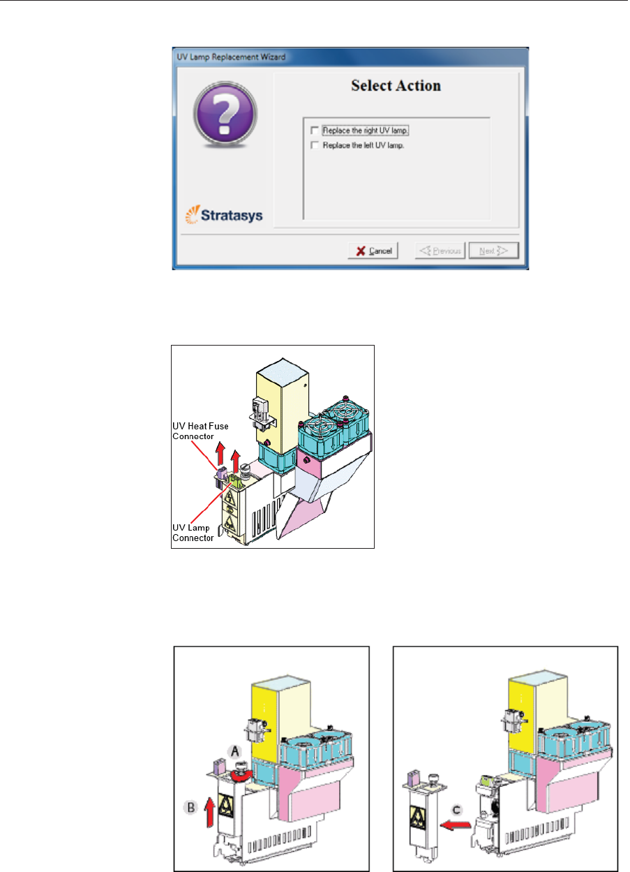
Operating & Maintaining the Stratasys P750K 3D Printer
6–62 DOC08010 Rev. A (DRAFT 1)
4. SelectȱtheȱUVȱlamp(s)ȱtoȱbeȱreplacedȱandȱclickȱNext.
Figure 6-100: UV lamp selection screen
5. DisconnectȱtheȱUVȬlampȱpowerȱconnectorȱandȱtheȱUVȱheatȱfuseȱ
connector.
Figure 6-101: Disconnecting the UV lamp
Note: Do not disconnect the power connection to the cooling fans.
6. LoosenȱtheȱscrewȱsecuringȱtheȱUVȱlampȱcoverȱ(A),ȱandȱpullȱtheȱcoverȱ
upȱ(B),ȱthenȱoutȱ(C).
Figure 6-102: Removing the UV lamp cover
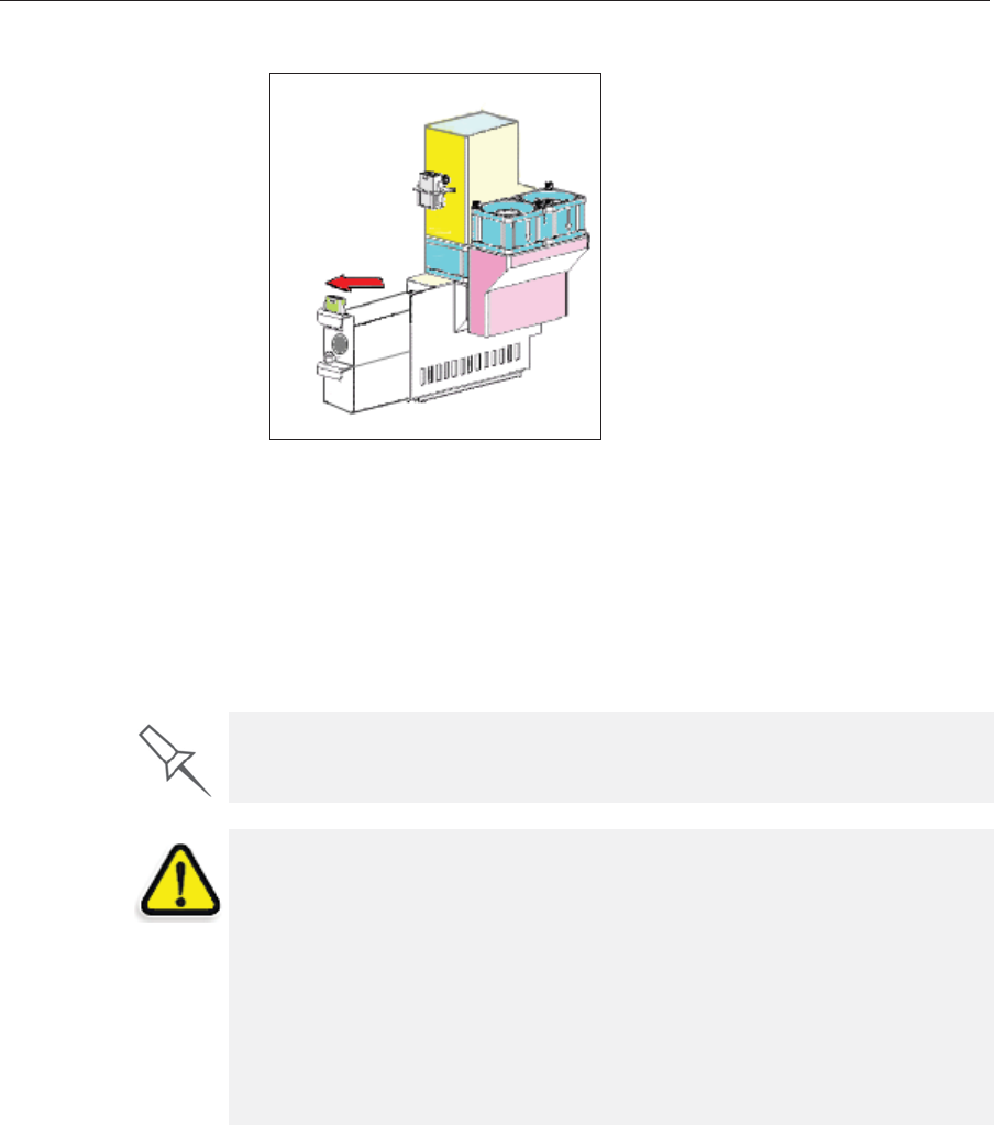
DOC08010 Rev. A (DRAFT 1) 6–63
Stratasys P750K User Guide
7. Pullȱtheȱlampȱreflectorȱoutȱofȱtheȱprintȱblock.
Figure 6-103: Removing the UV lamp reflector
8. Inspectȱtheȱnewȱlampȱreflector,ȱandȱmakeȱsureȱthatȱaȱblackȱstripȱisȱ
attachedȱtoȱtheȱinsideȱofȱit.ȱIfȱnot,ȱinstallȱone—onȱtheȱsideȱofȱtheȱ
reflectorȱoppositeȱ(notȱnextȱto)ȱtheȱprintȱblock.
Note: Extra black strips are included in the printer Start-up Kit. If
necessary, you can remove the black strip from the old reflector and install
it in the new reflector (as long as the black paint has not faded).
9. Discardȱtheȱoldȱreflectorȱandȱlamp.
Dispose of the used UV lamp in accordance with environmental and safety
requirements.
WARNING: Broken lamp hazard.
UV lamps contain mercury. Deal with broken lamps with caution.
¾Ventilate the room thoroughly.
¾Use protective gloves when collecting mercury and lamp components.
¾Remove spilled mercury with a method that prevents the generation of
mercury vapor, such as a syringe, packing tape or paper.
¾Place the broken lamp, mercury and contaminated materials in an air-
tight, non-metallic container.
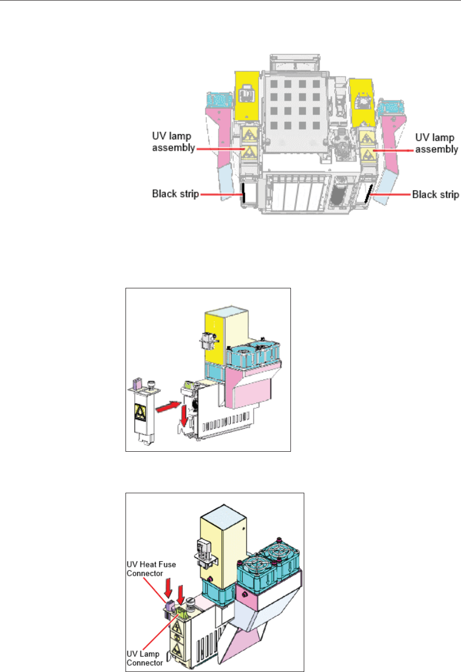
Operating & Maintaining the Stratasys P750K 3D Printer
6–64 DOC08010 Rev. A (DRAFT 1)
10. InsertȱtheȱnewȱUVȱlamp/reflectorȱunitȱintoȱtheȱhousingȱnextȱtoȱtheȱprintȱ
block.
Figure 6-104: Print block and UV lamp assembly, showing correct placement of
black strip
11. Replaceȱtheȱlampȱcoverȱbyȱinsertingȱitȱintoȱtheȱslotȱonȱtheȱbottomȱofȱtheȱ
housing,ȱandȱtightenȱtheȱsecuringȱscrewȱonȱtop.
Figure 6-105: Replacing the lamp cover
12. Reconnectȱtheȱpowerȱandȱheatȱfuseȱconnectors.
Figure 6-106: Connecting the UV lamp
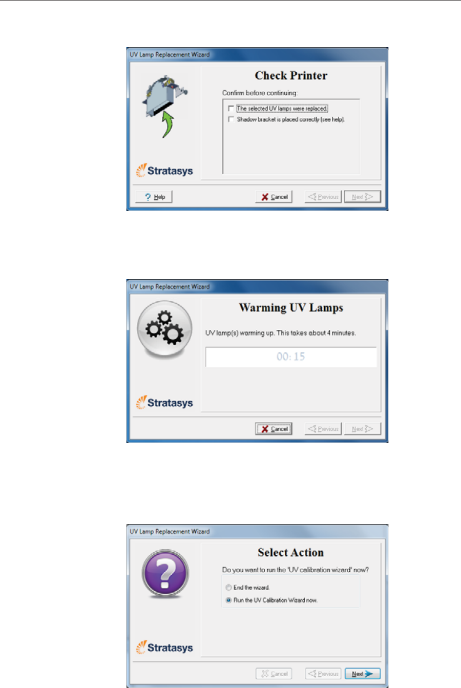
DOC08010 Rev. A (DRAFT 1) 6–65
Stratasys P750K User Guide
13. Inȱtheȱwizardȱscreen,ȱconfirmȱthatȱyouȱhaveȱreplacedȱtheȱlamp(s)ȱandȱ
thatȱtheȱblackȱstripȱisȱattached,ȱthenȱclickȱNext.
Figure 6-107: UV-installation confirmation screen
Theȱwizardȱoperatesȱtheȱlampsȱandȱchecksȱifȱtheirȱpowerȱisȱwithinȱtheȱ
acceptableȱrangeȱforȱeachȱprintingȱmode.ȱ(Theȱmodeȱcurrentlyȱbeingȱ
checkedȱappearsȱinȱtheȱlowerȬleftȱcornerȱofȱtheȱprinterȱinterface.)
Figure 6-108: Status screen during UV lamp check
14. AfterȱreplacingȱaȱUVȱlamp,ȱitȱisȱrecommendedȱthatȱyouȱcalibrateȱitsȱ
powerȱforȱtheȱvariousȱprintingȱmodes.ȱTheȱnextȱscreenȱallowsȱyouȱtoȱ
continueȱtoȱtheȱUVȱCalibrationȱwizardȱ(seeȱ“TestingȱandȱCalibratingȱ
theȱUVȱLamps”ȱonȱpage 53).
Figure 6-109: Final wizard screen
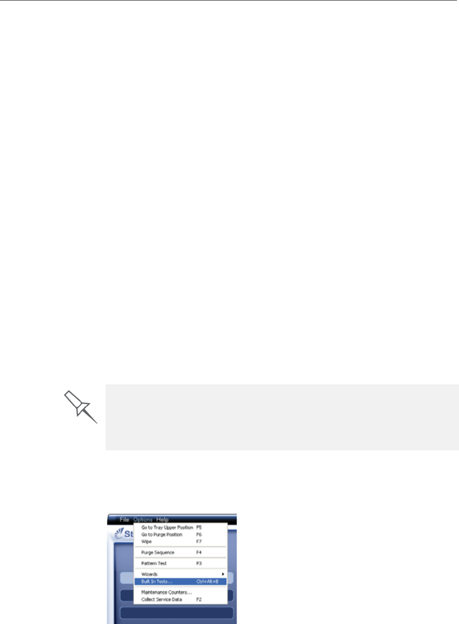
Operating & Maintaining the Stratasys P750K 3D Printer
6–66 DOC08010 Rev. A (DRAFT 1)
Built-in Tests Theȱprinterȱapplicationȱcontainsȱaȱsuiteȱofȱtestsȱforȱregularlyȱcheckingȱtheȱ
hardwareȱandȱsoftware,ȱandȱforȱtroubleshooting.ȱYouȱcanȱconfigureȱbasicȱ
communicationsȱandȱenvironmentȱtestsȱtoȱrunȱautomatically,ȱwhenȱtheȱ
Stratasysȱsoftwareȱopens.ȱInȱaddition,ȱyouȱcanȱrunȱaȱmoreȱcomprehensiveȱ
setȱofȱtestsȱbeforeȱprocessingȱaȱprintȱjob,ȱasȱaȱsystemȱcheck,ȱtoȱensureȱ
optimumȱprintingȱresults.ȱ
Becauseȱrunningȱtheȱtestsȱeffectsȱtheȱoperationȱofȱtheȱprinter,ȱyouȱcanȱonlyȱ
openȱtheȱBuiltȬinȱTestsȱinterfaceȱwhenȱtheȱsystemȱisȱnotȱprinting.
Theȱtestȱsuiteȱfeatures:
•TheȱorganizationȱofȱprintingȬrelatedȱtasksȱinȱcategories:
Communicationsȱ
Dataȱcardsȱ
Temperaturesȱ
Voltagesȱ
Encoderȱrepeatabilityȱ
PrintȬheadȱheating
PrintȬheadȱfillingȱ
•Aȱclearȱdisplayȱofȱtestȱresultsȱandȱtheȱsourceȱofȱanyȱfailures,ȱenablingȱ
youȱtoȱdetermineȱifȱprintingȱisȱpossibleȱorȱworthwhile.ȱ
•Theȱabilityȱtoȱmonitorȱtestȱresultsȱforȱspecificȱcomponents.
•Troubleshootingȱtips.
Runningȱtheseȱtestsȱcanȱhelpȱidentifyȱproblemsȱinȱtheȱprinterȱhardwareȱandȱ
software.ȱAȱlargeȱnumberȱofȱhardwareȱdefectsȱ(orȱnearȬdefects)ȱwarnsȱyouȱ
ofȱpossibleȱprintingȱproblems,ȱeitherȱforȱcurrentȱorȱfutureȱjobs.
Accessing
Built-in Tests To open the Built-in Tests screen, do one of the following:
•FromȱtheȱOptionsȱmenu,ȱselectȱBuilt-In Tests.
•PressȱCtrl+Alt+B.
Figure 6-110: Selecting Built-In Tests from the Options menu
Stratasys recommends running the built-in tests in the following cases:
¾as a routine test, once every two weeks
¾as a system check, before major (long) jobs
¾as needed, for troubleshooting
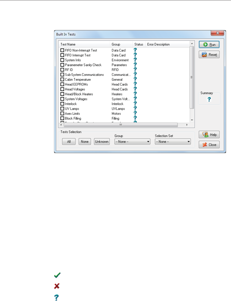
DOC08010 Rev. A (DRAFT 1) 6–67
Stratasys P750K User Guide
Test Interface TheȱBuiltȱInȱTestsȱscreenȱlistsȱpreȬconfiguredȱtests,ȱgroupedȱbyȱcomponentȱ
categories.ȱInȱthisȱscreen,ȱyouȱselectȱandȱrunȱtests,ȱandȱtheȱresultsȱareȱ
displayed.
Figure 6-111: Built In Tests screen
Test List TestȱName
Thisȱcolumnȱlistsȱallȱofȱtheȱtests,ȱtogetherȱwithȱselectionȱcheckȱboxes.ȱ
Clickȱtheȱcheckȱboxesȱtoȱselectȱtheȱtestsȱyouȱwantȱtoȱrun.ȱToȱremoveȱaȱ
selection,ȱclickȱtheȱcheckȱboxȱagain.ȱToȱquicklyȱselectȱallȱofȱtheȱtestsȱinȱaȱ
componentȱcategory,ȱuseȱtheȱGroupȱdropȬdownȱlistȱatȱtheȱbottomȱofȱtheȱ
screen.
Group
Thisȱcolumnȱshowsȱtheȱcomponentȱcategoriesȱforȱeachȱtest.ȱ
ThisȱtellsȱyouȱwhichȱtestsȱareȱrunȱwhenȱselectingȱaȱcategoryȱfromȱtheȱGroupȱ
dropȬdownȱlistȱatȱtheȱbottomȱofȱtheȱscreen.
Status
Thisȱcolumnȱshowsȱtheȱresultsȱofȱeachȱtestȱafterȱyouȱrunȱit:
Testȱsuccessfullyȱcompleted.
Testȱfailed.ȱ
Unknownȱresults.ȱ(Theȱtestȱhasȱnotȱbeenȱrunȱyet.)
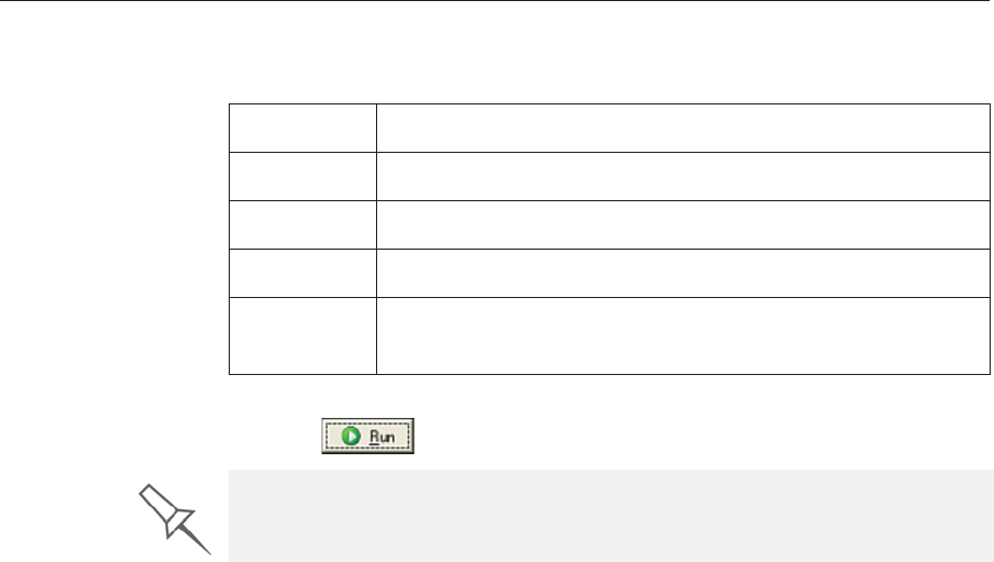
Operating & Maintaining the Stratasys P750K 3D Printer
6–68 DOC08010 Rev. A (DRAFT 1)
Test Selection Area InȱtheȱTestȱSelectionȱarea,ȱatȱtheȱbottomȱofȱtheȱscreen,ȱyouȱcanȱquicklyȱselectȱ
orȱdeȬselectȱtestsȱbyȱtheirȱcharacteristics:
Running Tests To run the selected tests:
¾Clickȱ.
Test Results To save and view a report of all of the tests:
¾UseȱtheȱSaveȱandȱViewȱcommandȱbuttonsȱ(seeȱbelow).
All Clickȱtoȱselectȱallȱofȱtheȱtestsȱinȱtheȱlist.
None ClickȱtoȱdeȬselectȱallȱofȱtheȱtestsȱinȱtheȱlist.
Unknown Clickȱtoȱselectȱallȱtestȱthatȱhaveȱnotȱbeenȱrunȱyetȱ(Status = ?).
Group Useȱthisȱmenuȱtoȱselectȱtestsȱbyȱcomponentȱcategory.
Selection
Set UseȱthisȱmenuȱtoȱselectȱaȱpreȬconfiguredȱsetȱofȱtestsȱtoȱrunȱatȱ
specifiedȱtimesȱ(computerȱstartup,ȱbeforeȱprinting,ȱetc.).
After you run a test, the Save and View command buttons are added to the
Built In Tests screen (see below).
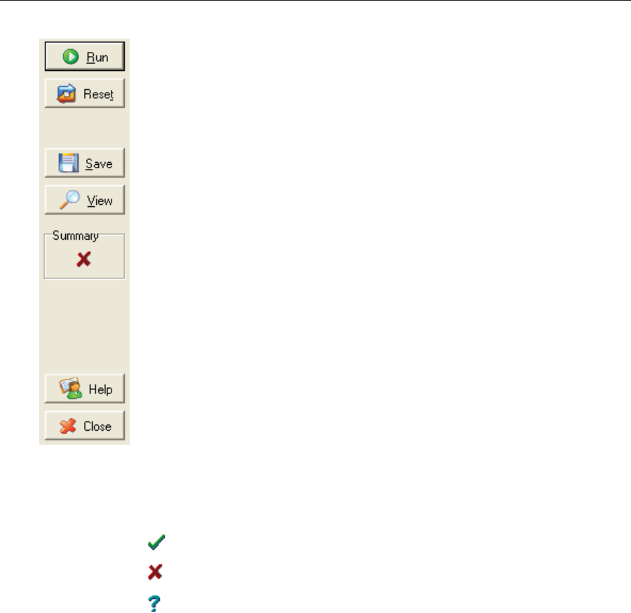
DOC08010 Rev. A (DRAFT 1) 6–69
Stratasys P750K User Guide
Command Buttons Youȱclickȱtheȱcommandȱbuttons,ȱonȱtheȱrightȱsideȱofȱtheȱscreen,ȱtoȱperformȱ
theȱfollowingȱoperations:
Run
Clickȱtoȱrunȱtheȱselectedȱtests.
Reset
Clickȱtoȱclearȱpreviouslyȱrunȱtests.ȱThisȱreturnsȱtheȱstatusȱofȱeachȱtestȱtoȱ
Unknownȱ(?).
Save
Clickȱtoȱsaveȱaȱreportȱthatȱsummarizesȱtheȱtestsȱrun.ȱTheȱreportȱisȱsavedȱasȱ
anȱHTMLȱfile.ȱYouȱcanȱsaveȱanyȱnumberȱofȱreportsȱforȱtheȱtestsȱyouȱrun;ȱtheȱ
nameȱofȱtheȱfileȱsavedȱisȱBITReport [date][time].htm.ȱByȱdefault,ȱtheseȱfilesȱ
areȱsavedȱinȱtheȱStratasysȱinstallationȱfolder,ȱbutȱyouȱcanȱsaveȱitȱinȱanyȱotherȱ
folder.
View
Clickȱtoȱdisplayȱtheȱlatestȱtestȱreportȱthatȱyouȱsaved.ȱ(Youȱcanȱviewȱotherȱ
testȱreportsȱbyȱopeningȱtheȱrelevantȱfilesȱinȱyourȱWebȱbrowser.ȱToȱdoȱso,ȱ
openȱWindowsȱExplorer,ȱandȱdoubleȱclickȱtheȱBITReportȱfile.)
Close
ClickȱtoȱcloseȱtheȱBuiltȬinȱTestsȱscreen.
Summary Onȱtheȱrightȱsideȱofȱtheȱscreen,ȱaȱsymbolȱrepresentsȱtheȱcombinedȱresultsȱofȱ
allȱtheȱtestsȱrun,ȱusingȱtheȱsymbolsȱfromȱtheȱStatusȱcolumn.
Allȱtestsȱsuccessfullyȱcompleted.
Atȱleastȱoneȱtestȱfailed.
Notȱallȱtestsȱperformed.

Operating & Maintaining the Stratasys P750K 3D Printer
6–70 DOC08010 Rev. A (DRAFT 1)
Test Descriptions
and
Troubleshooting
TheȱfollowingȱtableȱlistsȱtheȱnameȱofȱeachȱtestȱinȱtheȱBuiltȬinȱTestsȱsuite,ȱ
togetherȱwithȱitsȱdescriptionȱandȱaȱpossibleȱreasonȱforȱitsȱfailure.ȱIfȱyouȱ
needȱassistance,ȱcontactȱyourȱStratasysȱserviceȱprovider.
Test Name Description Possible Reason for Failure
SubȬSystemȱ
Communication TestsȱcommunicationsȱbetweenȱEdenȱ
components. •Disconnectedȱcommunicationsȱcable.
•Faultyȱcable.
FIFOȱNonȬInterrupt/
FIFOȱInterrupt •TestsȱtheȱdataȱqueueȱinȱtheȱDATAȱPCIȱ
card.
•TestsȱtheȱWindowsȱinterrupt.
•IfȱbothȱFIFOȱtestsȱfail:ȱ
FaultyȱDATA_PCIȱcard.
•IfȱonlyȱtheȱFIFOȱInterruptȱtestȱfails:
FaultyȱWindowsȱinterrupt.
Encoder Testsȱtheȱencoderȇsȱreliabilityȱbyȱ
comparingȱreadingsȱfromȱmultipleȱrunsȱ
alongȱtheȱXȬaxis.
Faultyȱencoder.
SystemȱInfo Comparesȱtheȱfollowingȱparameterȱ
valuesȱwithȱtheȱminimumȱ
requirements.
•physicalȱmemory
•availableȱmemory
•freeȱspaceȱonȱdisk
•monitorȱresolution
FailureȱofȱRAMȱmemoryȱallocationȱinȱtheȱ
printerȱcomputer.
RFID VerifiesȱtheȱpresenceȱofȱRFIDȱtagsȱonȱallȱ
loadedȱmaterialȱcartridges,ȱandȱtestsȱ
themȱbyȱwritingȱtoȱandȱreadingȱfromȱ
eachȱone.
•FaultyȱRFIDȱreader.
•FaultyȱRFIDȱreaderȱpowerȱsupply.
•FaultyȱorȱmisalignedȱRFIDȱtag.
•Highȱlevelȱofȱelectromagneticȱnoiseȱ
aroundȱtheȱRFIDȱtag.
SystemȱVoltages Checksȱifȱtheȱfollowingȱvoltagesȱareȱ
withinȱ5%ȱofȱtheȱrequiredȱvoltage:
•40VȱtoȱtheȱprintȱheadsȱbyȱtheȱVPPȱ
powerȱsupply
•12Vȱtoȱtheȱheightȱthermistorsȱbyȱtheȱ
VDDȱpowerȱsupply
•VPPȱpowerȱsupply:ȱ
Faultyȱheadȱdrive(s).
•VDDȱpowerȱsupply:ȱ
Faultyȱheightȱthermistor(s).
BlockȱFilling Analyzesȱtheȱthermistorȱreadingsȱwhenȱ
theȱblockȱisȱfullȱandȱwhenȱitȱisȱempty. Faultyȱthermistor.
Interlock Testsȱtheȱinterlockȱinȱtheȱprinterȱcover. •Failureȱofȱinterlockȱmechanism.
•Faultyȱlatch.ȱ
•Disconnectedȱcable.
CabinȱTemperature Testsȱtheȱtemperatureȱlevelȱinȱtheȱ
buildȬtrayȱarea. Faultyȱtemperatureȱsensorȱ(OHDB).
HeadȱEEPROM Testsȱtheȱread/writeȱcapabilitiesȱofȱtheȱ
printȬheadȱdriverȱcards. FaultyȱprintȬheadȱdriverȱcard(s).
HeadȱVoltage Checksȱtheȱcontrolȱofȱvoltagesȱsuppliedȱ
toȱtheȱprintȱheads. FaultyȱprintȬheadȱdriverȱcard(s).
Head/BlockȱHeaters Testsȱtheȱheatersȱinȱtheȱprintȱheadsȱandȱ
inȱtheȱprintȬblockȱbody. Faultyȱheatersȱorȱthermistors.
UVȱLamps TestsȱeachȱUVȱlampȱatȱtheȱHighȱQualityȱ
powerȱlevel. FaultyȱUVȱlamp.
FaultyȱUVȱpowerȱsupply.
DisconnectedȱUVȱcable.
AxesȱLimit Testsȱtheȱhardwareȱandȱsoftwareȱlimitsȱ
ofȱallȱaxes. Faultyȱhardwareȱsensors.ȱ
WrongȱMaxȱPositionȱparameter.
ParameterȱSanityȱCheck Comparesȱtheȱvaluesȱofȱallȱprinterȱ
parametersȱ(inȱcfgȱfiles)ȱtoȱtheȱrequiredȱ
values.
Oneȱorȱmoreȱofȱtheȱprinterȱparametersȱisȱ
notȱwithinȱtheȱrequiredȱrange.ȱ
DetailsȱappearȱinȱtheȱBITȱreport.
Vacuum Testsȱtheȱvacuumȱlevelȱinȱtheȱprintȱ
block. •Faultyȱvacuumȱsensor.ȱ
•Vacuumȱleakage.ȱ
•Wrongȱparameters.
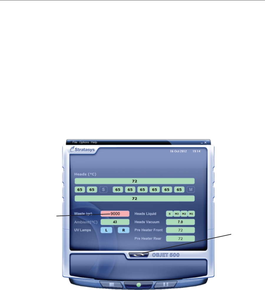
DOC08010 Rev. A (DRAFT 1) 6–71
Stratasys P750K User Guide
Replacing the
Waste
Container
Printerȱwasteȱcontainsȱpartiallyȱcuredȱpolymericȱmaterial,ȱcollectedȱduringȱ
normalȱoperationȱandȱmaintenanceȱofȱtheȱprinter.ȱForȱsafetyȱandȱ
environmentalȱreasons,ȱthisȱmaterialȱisȱkeptȱinȱaȱspecialȱleakȬproof,ȱ
disposableȱcontainer.
Theȱcontainerȱhasȱaȱcapacityȱofȱ10ȱkilogramsȱofȱwasteȱmaterial—usuallyȱ
enoughȱforȱseveralȱmonthsȱofȱprinterȱuse.ȱTheȱprinterȱapplicationȱdisplaysȱ
aȱwarningȱmessageȱwhenȱthereȱareȱ9ȱkilogramsȱofȱmaterialȱinȱtheȱcontainer,ȱ
andȱstopsȱtheȱprintingȱwhenȱtheȱnetȱweightȱreachesȱ9.5ȱkilograms.ȱAboveȱ9ȱ
kilograms,ȱtheȱsoftwareȱdoesȱnotȱallowȱyouȱtoȱstartȱaȱprintȱjobȱ(orȱaȱprintingȱ
activity)ȱuntilȱyouȱreplaceȱtheȱwasteȱcontainer.ȱYouȱcanȱmonitorȱtheȱweightȱ
ofȱtheȱwasteȱcontainerȱinȱtheȱMaintenanceȱscreenȱofȱtheȱprinterȱinterface.ȱYouȱ
canȱalsoȱvisuallyȱinspectȱtheȱlevelȱofȱwasteȱinȱtheȱcontainer.ȱ(Toȱaccessȱit,ȱseeȱ
page 73.)
To monitor the waste weight (and other indicators) in the printer:
¾Inȱtheȱmainȱprinterȱinterfaceȱscreen,ȱclickȱtheȱdisplayȱtoggleȱtoȱviewȱtheȱ
printerȱindicators.
Waste weight
Display
toggle button
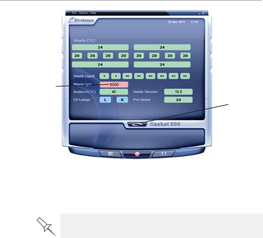
Operating & Maintaining the Stratasys P750K 3D Printer
6–72 DOC08010 Rev. A (DRAFT 1)
Figure 6-112: Printer interface, showing waste weight (red background indicates
operator alert)
Theȱwasteȱcontainerȱconsistsȱofȱaȱplasticȱcontainerȱinsideȱaȱcardboardȱbox.ȱ
Youȱtypicallyȱdisposeȱofȱtheȱentireȱwasteȱcontainer—includingȱtheȱbox.ȱ
Therefore,ȱyouȱmustȱassembleȱaȱnewȱboxȱandȱinsertȱaȱnewȱplasticȱcontainerȱ
beforeȱyouȱcanȱinstallȱitȱinȱtheȱprinter.
To prepare a new waste container:
1. Assembleȱtheȱcardboardȱbox,ȱmakingȱsureȱtoȱpunchȱoutȱtheȱperforatedȱ
sections.
2. Placeȱaȱnewȱplasticȱcontainerȱintoȱtheȱbox.
Note: Do not close the box until you connect the waste drain tube from the
printer.
Waste weight
Display
toggle button
Replacement boxes, plastic containers, and sealing caps are supplied in the
Stratasys printer start-up kit and in the preventive-maintenance kit.
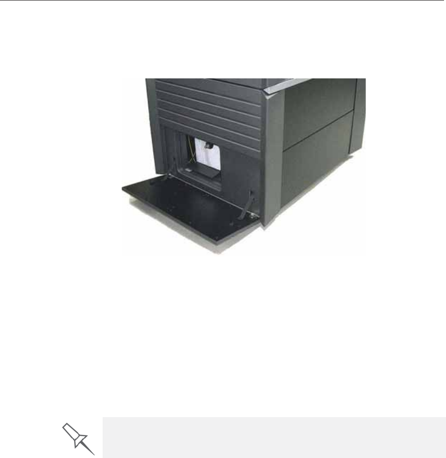
DOC08010 Rev. A (DRAFT 1) 6–73
Stratasys P750K User Guide
To replace the waste container:
1. LocateȱtheȱdoorȱonȱtheȱlowerȬleftȱsideȱofȱtheȱprinter.
2. PushȱinȱtheȱtopȬcenterȱofȱtheȱdoorȱtoȱreleaseȱtheȱlatchȱandȱopenȱtheȱ
door.
Figure 6-113: Accessing the waste container
3. Carefullyȱslideȱoutȱtheȱwasteȱcontainerȱtoȱremoveȱitȱfromȱtheȱprinter.
4. Closeȱtheȱfullȱcontainerȱwithȱtheȱcapȱsuppliedȱwithȱtheȱnewȱwasteȱ
container.
5. CloseȱtheȱnewȱwasteȬcontainerȱbox,ȱusingȱtapeȱtoȱholdȱitȱclosed.ȱ
•Theȱcontainerȱshouldȱbeȱonȱtheȱextremeȱrightȱsideȱofȱtheȱ
compartment.ȱ
•Makeȱsureȱthatȱtheȱwasteȱdrainȱtubeȱisȱnotȱcrimpedȱandȱthatȱitȱisȱnotȱ
pinchedȱbyȱtheȱcontainer.
6. Closeȱtheȱwasteȱcompartmentȱdoor.
Cleaning the
Exterior Panels TheȱpaintedȱexteriorȱplasticȱpanelsȱofȱStratasysȱ3Dȱprintersȱhaveȱaȱdurableȱ
finish,ȱofferingȱexcellentȱchemicalȱresistanceȱtoȱcommonȱcleaningȱmaterials.ȱ
Followȱtheȱrecommendationsȱbelowȱwhenȱcleaningȱtheseȱareasȱofȱtheȱ
printer.
AcceptableȱCleaningȱAgents
•mildȱsoapȱsolutionȱ
•commonȱhouseholdȱcleanersȱandȱwindowȱcleaners
•commonȱcommercialȱandȱindustrialȱdetergents,ȱ5%ȱsolutionȱinȱwaterȱ
•alcoholȱ(ethanol,ȱisopropanol),ȱ10%ȱtoȱ40%ȱsolutionȱinȱwater
Wipeȱtheȱexteriorȱofȱtheȱprinter,ȱusingȱaȱsoftȱclothȱmoistenedȱwithȱtheȱ
cleaningȱsolution.
Dispose of the full waste container in accordance with environmental and
safety requirements.

Operating & Maintaining the Stratasys P750K 3D Printer
6–74 DOC08010 Rev. A (DRAFT 1)
UnacceptableȱMaterials
•industrialȱsolventsȱ
•cleaningȱagentsȱcontainingȱhydrocarbons,ȱketones,ȱestersȱandȱlacquerȱ
thinners
•sprayȱdisinfectants
•abrasivesȱandȱagentsȱwhichȱcouldȱwearȱawayȱtheȱpanelȱfinish

DOC08010 Rev. A (DRAFT 1) 7–1
Handling Printed Models
RemovingȱModelsȱAfterȱPrinting.............................................................. 2
RemovingȱtheȱSupportȱMaterial................................................................ 2
PostȬPrintingȱTreatmentȱforȱModelsȱPrintedȱwithȱObjetȱVeroClear..... 4
StoringȱModels............................................................................................. 5

Handling Printed Models
7–2 DOC08010 Rev. A (DRAFT 1)
Removing Models After Printing
Afterȱprintingȱmodels,ȱyouȱshouldȱallowȱthemȱtoȱcoolȱasȱmuchȱasȱpossibleȱ
beforeȱhandlingȱthem.ȱIfȱadditionalȱmodelsȱdoȱnotȱhaveȱtoȱbeȱproducedȱonȱ
theȱprinter,ȱitȱisȱbestȱtoȱletȱtheȱprintedȱmodelsȱcoolȱinȱtheȱprinter,ȱwithȱtheȱ
coverȱclosed,ȱasȱlongȱasȱpossible.ȱ
If the printer must be used to produce additional models as soon as
possible:
1. Letȱtheȱprintedȱmodelsȱcoolȱonȱtheȱbuildȱtrayȱforȱatȱleastȱ10ȱminutes.ȱ
2. Veryȱcarefully,ȱremoveȱtheȱmodelsȱfromȱtheȱtrayȱwithȱaȱscraperȱorȱ
spatulaȱ(suppliedȱinȱtheȱtoolȱkit),ȱtakingȱcareȱnotȱtoȱpryȱorȱbendȱtheȱ
model.
3. Placeȱtheȱmodelsȱonȱaȱflatȱsurface,ȱandȱcoverȱthemȱwithȱaȱcardboardȱ
boxȱorȱpaperȱhood.
Thisȱallowsȱtheȱmodelsȱtoȱcoolȱslowlyȱandȱevenly.
4. Letȱtheȱmodelsȱcoolȱforȱseveralȱhours.
Removing the Support Material
Afterȱprintedȱmodelsȱhaveȱcooled,ȱtheȱsupportȱmaterialȱmustȱbeȱremoved.ȱ
Thisȱcanȱbeȱdoneȱbyȱdifferentȱmethods,ȱdependingȱonȱtheȱsizeȱofȱtheȱmodel,ȱ
howȱdelicateȱitȱis,ȱtheȱamountȱandȱlocationȱofȱtheȱsupportȱmaterial,ȱandȱ
otherȱfactors.ȱUseȱtheȱfollowingȱmethodsȱasȱaȱguide,ȱandȱadaptȱthemȱ(orȱaȱ
combinationȱofȱthem)ȱforȱfinishingȱtheȱmodelsȱyouȱareȱhandling.
Removing Excess
Support Material by
Hand
Whileȱwearingȱprotectiveȱgloves,ȱbreakȱawayȱexcessȱsupportȱmaterialȱonȱ
theȱoutsideȱofȱtheȱmodel.ȱForȱdelicateȱmodels,ȱuseȱaȱtoothpick,ȱpinȱorȱsmallȱ
brushȱafterȱdippingȱtheȱmodelȱinȱwater.
Removing Support
Material with Water
Pressure
Forȱmostȱmodels,ȱtheȱmostȱefficientȱwayȱtoȱremoveȱsupportȱmaterialȱisȱbyȱ
usingȱaȱhighȬpressureȱwaterȱjet.ȱOneȱsuitableȱsystemȱisȱtheȱBalcoȱWaterJetȱ
cleaningȱunit.ȱThisȱdeviceȱisȱmarketedȱbyȱStratasys.
WARNING: Wear protective gloves when handling printed models
before they are washed.
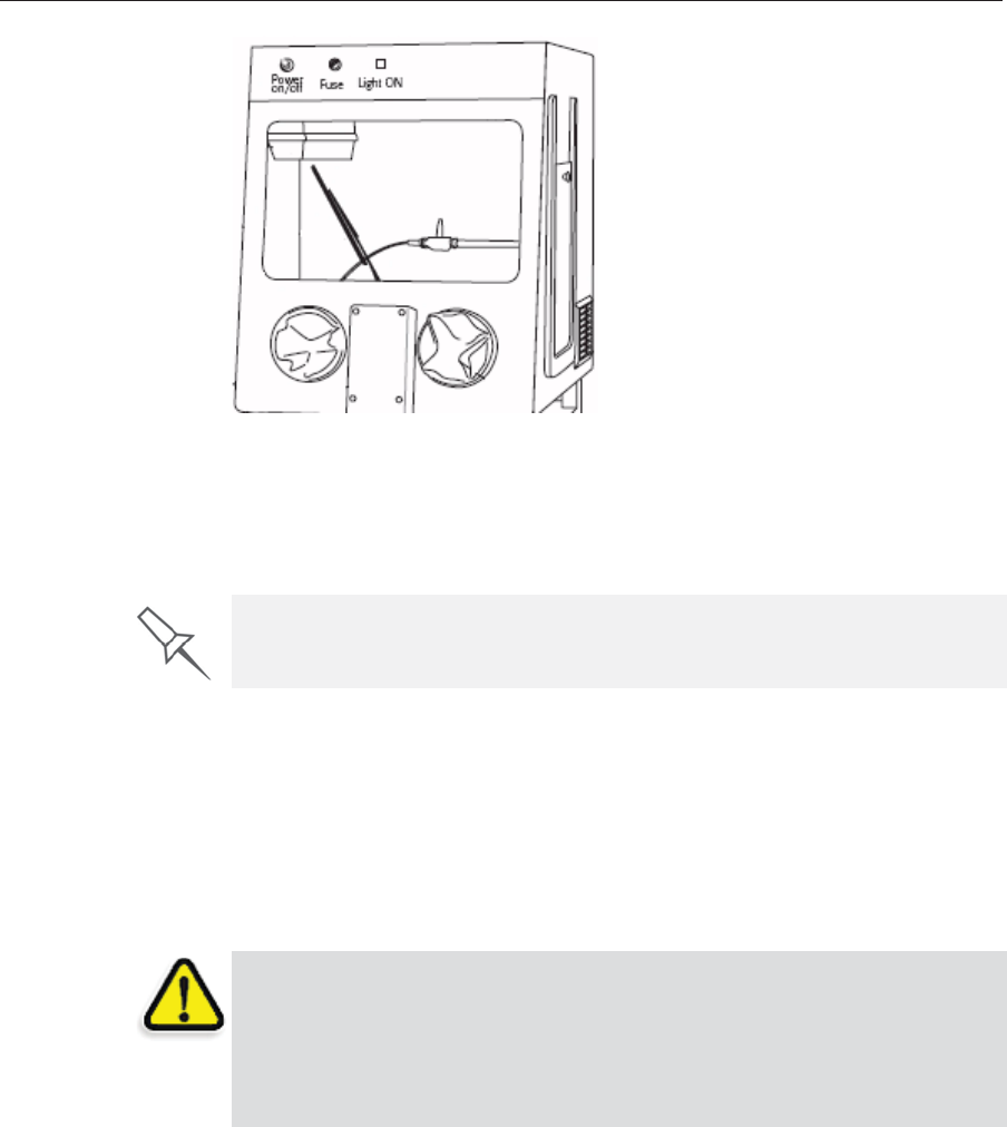
DOC08010 Rev. A (DRAFT 1) 7–3
Stratasys P750K User Guide
Figure 7-1: Balco WaterJet Cleaning Unit
Toȱcleanȱaȱmodelȱusingȱthisȱdevice,ȱyouȱplaceȱitȱinȱtheȱchamber,ȱandȱyouȱ
manipulateȱitȱandȱtheȱjetȱusingȱtheȱbuiltȬin,ȱwaterproofȱsleeves.ȱAȱpumpȱ
turnsȱordinaryȱtapȱwaterȱintoȱaȱhighȬpressureȱjet,ȱandȱaȱwiperȱkeepsȱtheȱ
windowȱclear.
Removing Support
Material with
Caustic Soda
Soakȱmodelsȱinȱaȱ1Ȭpercentȱsolutionȱofȱcausticȱsodaȱ(sodiumȱhydroxide)ȱtoȱ
removeȱsupportȱmaterialȱfromȱdifficultȬtoȬreachȱareasȱandȱtoȱgiveȱtheȱ
modelȱaȱsmooth,ȱcleanȱfinish.ȱTheȱamountȱofȱtimeȱyouȱsoakȱtheȱmodelȱinȱtheȱ
solutionȱdependsȱonȱhowȱdelicateȱitȱisȱandȱhowȱmuchȱsupportȱmaterialȱ
needsȱtoȱbeȱremoved,ȱbutȱitȱisȱtypicallyȱbetweenȱhalfȬanȬhourȱandȱseveralȱ
hours.ȱInȱanyȱcase,ȱyouȱshouldȱremoveȱasȱmuchȱsupportȱmaterialȱasȱ
possibleȱbeforeȱtheȱcausticȱsodaȱtreatment,ȱandȱrinseȱtheȱmodelȱthoroughlyȱ
(withȱaȱwaterȱjet)ȱafterwards.ȱ
Use caution when cleaning delicate models with high-pressure water systems.
WARNING: Caustic soda may cause chemical burns, scarring and
blindness. Mixing it with water generates heat that could ignite other
materials. Never pour water into a caustic soda solution. When diluting
the solution, always add caustic soda to water. Take adequate safety
precautions; always use nitrile gloves when handling caustic soda and
models soaked in it.
Handling Printed Models
7–4 DOC08010 Rev. A (DRAFT 1)
Post-Printing Treatment for Models Printed with Objet VeroClear
ModelsȱmadeȱwithȱObjetȱVeroClearȱ(RGD810)ȱhaveȱaȱslightȱyellowȱtintȱ
whenȱremovedȱfromȱtheȱprinter.ȱThisȱisȱespeciallyȱtrueȱforȱmodelsȱprintedȱ
withȱaȱglossyȱfinish.ȱTheȱyellowȱtintȱfadesȱnaturallyȱoverȱtime,ȱbutȱyouȱcanȱ
greatlyȱaccelerateȱthisȱprocessȱbyȱusingȱaȱsuitableȱphotobleachingȱ
treatment.
Asȱaȱrule,ȱbestȱclarityȱisȱachievedȱwhenȱpartsȱareȱprintedȱwithȱaȱmatteȱ
finish,ȱandȱtreatedȱasȱexplainedȱbelow.
Photobleachingȱmodelsȱinvolvesȱexposingȱthemȱtoȱlight.ȱToȱachieveȱhighlyȱ
controlledȱandȱpredictableȱresults,ȱaȱprofessionalȱilluminationȱchamberȱisȱ
recommended.ȱHowever,ȱadequateȱresultsȱmayȱbeȱobtainedȱusingȱordinaryȱ
deskȱlampsȱfittedȱwithȱsuitableȱfluorescentȱelements.
Photo-
Bleaching
Instructions
Followȱtheseȱinstructionsȱforȱphotobleachingȱprintedȱmodels.
•Theȱfluorescentȱlampsȱshouldȱbeȱratedȱ45W,ȱ6500K.
•Whenȱusingȱdeskȱlamps,ȱplaceȱtheȱmodelsȱinȱaȱcontainerȱlinedȱwithȱ
aluminumȱfoil.ȱUseȱatȱleastȱtwoȱlamps,ȱmoreȱwhenȱtreatingȱmodelsȱinȱaȱ
largeȱcontainer.
•Arrangeȱtheȱmodelsȱwithȱenoughȱspaceȱbetweenȱthemȱtoȱallowȱlightȱtoȱ
reachȱallȱsidesȱofȱeachȱmodel.
•Verifyȱthatȱtheȱambientȱtemperatureȱaroundȱtheȱmodelsȱisȱ
approximatelyȱ40 ºCȱ(104 ºF).ȱHigherȱtemperaturesȱmayȱcauseȱmodelȱ
distortion;ȱlowerȱtemperaturesȱmayȱnotȱproduceȱsatisfactoryȱresults.ȱ
Whenȱusingȱdeskȱlamps,ȱyouȱcanȱachieveȱtheȱrequiredȱtemperatureȱbyȱ
positioningȱtheȱlampsȱapproximatelyȱ10ȱcmȱ(4ȱin.)ȱaboveȱtheȱmodels.
•Inspectȱtheȱmodelsȱafterȱsixȱhoursȱofȱtreatment.ȱ
Forȱpartsȱwithȱaȱmatteȱfinish,ȱthisȱshouldȱbeȱenough.ȱPolishȱandȱ
lacquerȱtheȱparts.
Forȱpartsȱwithȱaȱglossyȱfinish,ȱcontinueȱtheȱphotobleachingȱ
treatmentȱforȱupȱtoȱ18ȱhoursȱmore.
InȱStratasysȱlaboratories,ȱthereȱwasȱaȱtintȱreductionȱofȱapproximatelyȱ
70%ȱwithinȱsixȱhours.ȱAfterȱ24ȱhours,ȱtintȱwasȱreducedȱbyȱ
approximatelyȱ90%.
Figure 7-2: Illumination chamber Figure 7-3: Desk lamps
More information about this treatment is available in the application note
VeroClear RGD810 Model Material.

DOC08010 Rev. A (DRAFT 1) 7–5
Stratasys P750K User Guide
Storing ModelsModelsȱareȱcuredȱasȱtheyȱareȱprinted,ȱmakingȱthemȱsafeȱandȱstableȱforȱaȱ
longȱtime.ȱHowever,ȱproperȱstorageȱconditionsȱareȱnecessaryȱtoȱpreventȱ
deforming.
•KeepȱprintedȱmodelsȱatȱroomȱtemperatureȱandȱinȱaȱlowȬhumidityȱ
environment.
•Doȱnotȱexposeȱmodelsȱtoȱdirectȱsunlightȱandȱotherȱheatȱsources.

Handling Printed Models
7–6 DOC08010 Rev. A (DRAFT 1)