Stratasys MATCAB Assembly of RFID reader and antenna boards User Manual user
Stratasys Ltd Assembly of RFID reader and antenna boards user
user manual

User Guide
English
Objet500 - Connex 3
3-D Printer System
DOC-07000 Rev. A
Copyright Copyright©2012ObjetLtd.Allrightsreserved.
ThisdocumentationcontainsproprietaryinformationofObjetLtd.Thisinformationissuppliedsolely
toassistauthorizedusersofObjet500‐Connex33‐Dprintingsystems.Nopartofthisdocumentmay
beusedforotherpurposes,anditmaynotbedisclosedtootherparties.
Thespecificationsonwhichthisdocumentisbasedaresubjecttochangewithoutnotice.
Nopartofthisbookmaybereproducedinanyformorbyanymeans,norstoredinadatabaseor
retrievalsystem,withoutpriorpermissioninwritingfromObjetLtd.
IfthisdocumentisdistributedasaPDFfile,youmayprintitforinternaluse.
Trademarks
ThefollowingareregisteredtrademarksofObjetLtd.:Objet®,FullCure®.
ThefollowingaretrademarksofObjetLtd.:Eden,Eden500V,Eden350V,Eden350,Eden330,Eden260,
Eden260V,Eden250,Connex,Connex500,Connex350,Objet30,Objet30‐Pro,Objet30‐Scholar,Objet24,
Alaris,Alaris30,PolyJet,PolyJetMatrix,CADMatrix,PolyLog,ObjetStudio,JobManager,SHR,
TangoBlack,TangoBlackPlus,TangoGray,TangoPlus,VeroBlue,VeroGray,VeroWhite,VeroWhitePlus,
VeroBlack,Durus,DurusWhite,RoseClear,Clear,ObjetGreen,DigitalMaterials.
MicrosoftandMicrosoftXParetrademarksofMicrosoftCorporation.
Allnamesofproductsandservicescitedinthisbookaretrademarksorregisteredtrademarksoftheir
respectivecompanies.
FCC Compliance Theequipmentreferredtointhisguidehasbeentestedandfoundtocomplywiththelimitsfora
ClassAdevicepursuanttopart15oftheFCCrules.Theselimitsprovidereasonableprotection
againstharmfulinterferencewhentheequipmentisoperatedinacommercialenvironment.Objet3‐D
printingsystemsgenerate,useandcanradiateradio‐frequencyenergyand,ifnotinstalledandused
inaccordancewiththeinstructionmanual,maycauseharmfulinterferencetoradiocommunications.
Operationofthisequipmentinaresidentialareaislikelytocauseharmfulinterference,inwhichcase
theuserwillberequiredtocorrecttheinterferenceathisownexpense.
The3‐Dprinterreferredtointhisguidecontainsatransmittermodule,FCCIDYH6‐MATCAB.
NOTE
:ObjetisnotresponsibleforradioorTVinterferencecausedbyunauthorizedmodificationto
thisequipment.Suchmodificationcouldvoidtheuser’sauthoritytooperatetheequipment.
Equipment Recycling
IntheEuropeanUnion,thissymbolindicatesthatwhenthelastuserwishestodiscardaproduct,it
mustbesenttoappropriatefacilitiesforrecoveryandrecycling.Forinformationaboutproper
disposal,checkyourpurchasecontract,orcontactthesupplieroftheequipment.
Limitation of Liability
Theproduct,softwareorservicesarebeingprovidedonan“asis”and“asavailable”basis.Exceptas
maybestatedspecificallyinyourcontract,ObjetLtd.expresslydisclaimsallwarrantiesofanykind,
whetherexpressorimplied,including,butnotlimitedto,anyimpliedwarrantiesofmerchantability,
fitnessforaparticularpurposeandnon‐infringement.
YouunderstandandagreethatObjetLtd.shallnotbeliableforanydirect,indirect,incidental,special,
consequentialorexemplarydamages,includingbutnotlimitedto,damagesforlossofprofits,
goodwill,use,dataorotherintangiblelosses(evenifObjethasbeenadvisedofthepossibilityofsuch
damages),resultingfrom:(i)theuseortheinabilitytousetheproductorsoftware;(ii)thecostof
procurementofsubstitutegoodsandservicesresultingfromanyproducts,goods,data,software,
informationorservicespurchased;(iii)unauthorizedaccesstooralterationofyourproducts,software
ordata;(iv)statementsorconductofanythirdparty;(v)anyothermatterrelatingtotheproduct,
software,orservices.
Thetextanddrawingshereinareforillustrationandreferenceonly.Thespecificationsonwhichthey
arebasedaresubjecttochange.ObjetLtd.may,atanytimeandwithoutnotice,makechangestothis
document.ObjetLtd.,foritselfandonbehalfofitssubsidiaries,assumesnoliabilityfortechnicalor
editorialerrorsoromissionsmadeherein,andshallnotbeliableforincidental,consequential,indirect,
orspecialdamages,including,withoutlimitation,lossofuse,lossoralterationofdata,delays,orlost
profitsorsavingsarisingfromtheuseofthisdocument.

iv
Patents ThisproductiscoveredbyoneormoreofthefollowingU.S.patents:
5,386,500
6,259,962
6,569,373
6,658,314
6,850,334
7,183,335
7,209,797
7,225,045
7,364,686
7,369,915
7,479,510
7,500,846
7,604,768
7,628,857
7,658,976
7,725,209
ObjetLtd.
http://www.objet.com
DOC‐07000
RevisionRev.A
October2012

DOC-07000 Rev. A
1AboutThisGuide
UsingThisGuide ............................................................................................................................... 1–2
ForMoreInformation........................................................................................................................ 1–2
TermsUsedinThisGuide................................................................................................................ 1–3
2 Safety
SafetyFeatures ................................................................................................................................... 2–2
SymbolsandWarningLabels .......................................................................................................... 2–3
SafetyGuidelines ............................................................................................................................... 2–4
PrinterInstallation .............................................................................................................................. 2–4
PrinterOperation ................................................................................................................................ 2–4
UVRadiation ....................................................................................................................................... 2–4
PrinterMaintenance ........................................................................................................................... 2–4
ModelandSupportMaterials ........................................................................................................... 2–5
FirstAidforWorkingwithPrintingMaterials.............................................................................. 2–6
ContactwithSkin................................................................................................................................ 2–6
ContactwithEyes ............................................................................................................................... 2–6
Ingestion............................................................................................................................................... 2–6
Inhalation ............................................................................................................................................. 2–6
WasteDisposal ................................................................................................................................... 2–7
3 IntroducingtheObjet 3‐D PrintingSystem
WorkConfigurations......................................................................................................................... 3–2
SourceFiles ......................................................................................................................................... 3–4
STLFiles ............................................................................................................................................... 3–4
SLCFiles............................................................................................................................................... 3–4
PrintingMaterials .............................................................................................................................. 3–4
AvailableMaterials............................................................................................................................. 3–5
Storage .................................................................................................................................................. 3–6
ShelfLife............................................................................................................................................... 3–6
ExposuretoLight................................................................................................................................ 3–6
SafetyConsiderations......................................................................................................................... 3–6
Disposal................................................................................................................................................ 3–6
WorkEnvironment............................................................................................................................ 3–7
WorkstationRequirements............................................................................................................... 3–8
PreparingFilesforUsewithObjet3‐DPrintingSystems............................................................ 3–9
ConvertingCADFilestoSTLFormat.............................................................................................. 3–9
ConvertingFilestoSLCFormat ....................................................................................................... 3–9
ObjetStudioSoftware ..................................................................................................................... 3–10
4 InstallingObjetSoftware
HowtoInstallSoftwarefortheObjet 3‐D Printing System ........................................................ 4–2
Contents

Objet500 - Connex 3 User Guide
vi
5UsingObjetStudio
ObjetStudioInterface........................................................................................................................ 5–3
RibbonCommands..............................................................................................................................5–5
ObjetStudioCommandsMenu.........................................................................................................5–7
ModelTreePane..................................................................................................................................5–7
PreparingModelsforProduction.................................................................................................... 5–8
OBJDFFiles:Overview.......................................................................................................................5–8
Model Files ...........................................................................................................................................5–8
PlacingObjectsontheBuildTray .....................................................................................................5–8
OpeningObjetTrayFiles..................................................................................................................5–12
Quick‐AccessModelCommands....................................................................................................5–14
CopyingandPastingObjects...........................................................................................................5–15
SelectingObjects ................................................................................................................................5–16
SurfaceFinish.....................................................................................................................................5–16
PositioningObjectsontheBuildTray .......................................................................................... 5–17
AutomaticOrientation......................................................................................................................5–17
AutomaticPlacement........................................................................................................................5–18
ManualPositioning ...........................................................................................................................5–19
ModelOrientation............................................................................................................................ 5–20
ManipulatingObjectsontheBuildTray ...................................................................................... 5–21
PositioningObjectsontheZ‐Axis...................................................................................................5–21
ValidObjectPlacement.....................................................................................................................5–22
UsingaGridtoPositionObjects .....................................................................................................5–23
MeasurementUnits...........................................................................................................................5–24
SettingModelDimensions ...............................................................................................................5–25
RepositioningObjects .......................................................................................................................5–25
ChanginganObject’sOrientation...................................................................................................5–27
FreezingModelOrientation.............................................................................................................5–28
DisplayOptions................................................................................................................................ 5–29
ViewingObjects.................................................................................................................................5–29
ScreenLayout.....................................................................................................................................5–31
TrayPerspective ................................................................................................................................5–32
SettingObjectColors.........................................................................................................................5–33
LoadingLargeFiles...........................................................................................................................5–34
LargeFileManipulation ...................................................................................................................5–34
ZoomOptions ....................................................................................................................................5–36
HandlingCompletedTrays............................................................................................................ 5–37
TrayValidation ..................................................................................................................................5–37
ProductionEstimates ........................................................................................................................ 5–38
E‐mailingObjetDigitalFiles............................................................................................................5–38
PrintingtheTrayFile ........................................................................................................................5–38
ApplyingAdditionalObjetStudioFeatures................................................................................ 5–40
DividingObjects ................................................................................................................................5–40
ChoosingtheSupportStrength .......................................................................................................5–41
“Hollow”—FillingModelswithSupportMaterial......................................................................5–42
DisplayingtheCrossSectionofObjects.........................................................................................5–43
SavingtheScreenDisplayasanImage File ..................................................................................5–44
ExportingandImportingObjetBuildTrays .................................................................................5–45
CustomizingObjetStudio............................................................................................................... 5–46
CreatingaQuickAccessToolbar ....................................................................................................5–46
HidingtheRibbon............................................................................................................................. 5–47
DisplayColors....................................................................................................................................5–48
KeyboardShortcuts...........................................................................................................................5–49
SettingUserPreferences...................................................................................................................5–50
ProfessionalModeFeatures ........................................................................................................... 5–51
DefaultSettings..................................................................................................................................5–52
OpenGLDriverConfiguration .......................................................................................................5–53

User Guide
DOC-07000 Rev. A vii
GettingAdditionalObjetStudioAssistance................................................................................ 5–55
MonitoringandManagingPrintJobs........................................................................................... 5–56
JobManagerScreen .......................................................................................................................... 5–56
SettingthePrinterConnection........................................................................................................ 5–58
Off‐lineMode .................................................................................................................................... 5–59
SettingtheRemotePrinterConnection(ClientMode)................................................................ 5–61
JobManagerCommands ................................................................................................................. 5–61
ConfiguringUserAlerts................................................................................................................... 5–64
PrintingtheTray ............................................................................................................................... 5–65
AdditionalServerFeatures.............................................................................................................. 5–65
6 Operating&MaintainingtheObjet303D Printer
StartingtheObjet30Printer.............................................................................................................. 6–2
LoadingModelandSupportCartridges ........................................................................................ 6–4
ProducingModels.............................................................................................................................. 6–6
PrinterInterfaceColor Key................................................................................................................ 6–8
PrintingIndicators .............................................................................................................................. 6–9
ResumingProductionAfterPrintinghasStopped ..................................................................... 6–10
ChangingtheModelMaterial........................................................................................................ 6–12
KeepingthePrinterinIdleMode.................................................................................................. 6–16
ShuttingDownthePrinter ............................................................................................................. 6–17
ShutdownWizard............................................................................................................................. 6–17
MaterialFlush/FillWizard .............................................................................................................. 6–19
MaintainingthePrinter................................................................................................................... 6–22
RoutineMaintenanceSchedule....................................................................................................... 6–22
CleaningthePrintHeads................................................................................................................. 6–23
PatternTest ........................................................................................................................................ 6–25
ImprovingPrintQuality .................................................................................................................. 6–26
CleaningandReplacingtheWiper ................................................................................................ 6–26
CleaningandReplacingtheRollerWasteCollector.................................................................... 6–30
AligningthePrintHeads................................................................................................................. 6–32
CalibratingtheLoadCells ............................................................................................................... 6–36
ReplacingtheOdorFilter ................................................................................................................ 6–38
ReplacingtheUVLamp................................................................................................................... 6–39
ReplacingtheWasteContainer....................................................................................................... 6–44
CleaningtheExteriorPanels ........................................................................................................... 6–46
Backing‐UpandRestoringPrinterSettings .................................................................................. 6–47
ReInitiateWizard .............................................................................................................................. 6–47
7 HandlingPrintedModels
RemovingModelsAfterPrinting .................................................................................................... 7–2
RemovingtheSupportMaterial ...................................................................................................... 7–2
Post‐PrintingTreatmentforModelsPrintedwithObjetVeroClear .......................................... 7–4
Photo‐BleachingInstructions ............................................................................................................ 7–4
StoringModels ................................................................................................................................... 7–5

Objet500 - Connex 3 User Guide
viii

DOC-07000 Rev. A 1–1
About This Guide
UsingThisGuide................................................................................. 2
ForMoreInformation ......................................................................... 2
TermsUsedinThisGuide.................................................................. 3

About This Guide
1–2
DOC-07000 Rev. A
Using This Guide
Thisuserguideprovidesinstructionsforinstalling,operatingand
maintainingObjet3‐Dprintingsystems.Itexplainshowtousefeatures,
andprovidespracticalexamplestoguideyouasyouusethesystem.
ThetextandfiguresinthisguidearebasedontheObjet500‐Connex33‐D
printer,printersoftwareversion58.1.0andObjetStudiosoftwareversion
9.2.
Thisguideassumesthat:
•allthehardware,software,andnetworkcomponentsofyourObjet
systemareinstalled,configured,andoperatingcorrectly.
•theoperatorhasaworkingknowledgeoftheWindows®PCplatform.
For More Information
Visithttp://www.objet.com/formoredetailsaboutObjet’stechnology,
productsandconsumables,andforserviceandsupportcontacts.
ForotherdocumentsthatrelatetoObjet500‐Connex33‐Dprinting
systems,andforthisdocumentinotherlanguages,contactyourregional
ObjetCustomerSupportoffice.
Ifyouhaveanyquestionsabouttheinformationpresentedinthis
document,orifyouhaveanycommentsorsuggestionsforfutureeditions,
pleasesendamessagetosupport@objet.com.

DOC-07000 Rev. A 1–3
Objet500 - Connex 3 User Guide
Terms Used in This Guide
buildtray InObjetStudio:Thesurfacedisplayedonthescreenthat
representstheactualbuildtrayintheprinter.
Intheprinter:Thesurfaceuponwhichmodelsareproduced.
cleaningfluid Cleanserforflushingmodelfeedtubesandtheprinting
block,usedtocompletelyremovemodelmaterialfromthe
systembeforeloadinganothertypeofmaterialintheprinter.
Thecleaningfluidissuppliedinmodel‐materialcartridges.
client/userworkstation TheworkstationonwhichObjetsoftwareisinstalled,used
forpreparingbuildtraysforproductiononObjetprinters.
(Thereisnolimittothenumberofclientworkstationsinthe
localnetwork.)
Objet™printer TheObjet3‐Dprinterreferredtointhisguide.
Printercomputer ThecomputerinsidetheObjetprinterthatoperatesit.(Thisis
sometimesreferredtoasthe“embedded”computer.)
Printerinterface TheGUI(graphicaluserinterface)usedforcontrollingthe
Objetprinter.
Printersoftware SoftwarerunningonthecomputerinsidetheObjetprinter,
thatcontrolsallprinteroperations.
DigitalMaterial™ Combinationsofmodelmaterialsfabricatedintheprinter
fromthetwobasicmodelmaterialsinstalled.
DigitalMaterialMode Theprintermodeusedtoprintajobusingtwodifferent
modelmaterials.(Thismodecanalsobeusedtoeliminatethe
needforperformingtheMaterialReplacementprocedure
whenprintingwithasinglemodelmaterial.)
host/serverworkstation TheworkstationthatinterfacesdirectlywiththeObjetprinter
andistypicallypositionednexttoit.
JobManager™ ThepartofObjetStudiosoftwarethatmanagesproduction
jobsbeforetheyaresenttotheObjetprinter.
mixedpart Modelswhosepartsareprintedusingmorethanonemodel
material.
mixedtray Abuildtraycontainingobjects,eachofwhichisdesignedto
beprintedusingadifferentmodelmaterial.
Modelmaterial Materialusedforbuildingmodels.
ObjetStudio™ Thesoftwarewithwhichuserspreparejobsforproducing
models.
OBJDF(ObjetDigitalFormat) Theextensionofafilethatcontainsinformationaboutthe
geometryofanobjectandthematerialsrequiredtoprintit.
objdffilesarecreatedinObjetStudio.

About This Guide
1–4
DOC-07000 Rev. A
OBJTF(ObjetTrayFormat) Theextensionofafilethatcontainsalloftheinformation
neededforamodel‐printingjobonObjet3‐Dprinters.An
objtffileisusedtosendaprintjobtoanObjet3‐Dprinter.
OBJZF(ObjetZFormat) Theextensionofacompressed“wrapper”filecontainingall
ofthefilesusedinanObjetStudiobuildtray.Usingobjzffiles,
aprintingjobcanbesavedasasinglefile,forconvenient
storageandtransfer.
PolyJetMatrix™ Thetechnologyofprintingmodelsbyjettingmultiple
materialssimultaneouslyfromtheprintheads.This
technologyenablesObjet500‐Connex3printerstoprintin
DigitalMaterialmode.
resin Thebasesubstancefromwhichphotopolymerprinting
materialsaremadeforuseinObjetprinters.InObjetStudio
andprinter‐applicationscreens,“resin”referstocartridgesof
modelandsupportmaterials.
SLC AfiletypeusedwithObjetsoftware.(Thesefilesarebitmaps
ofindividualslicesoftheobject.Formoreinformation,see
page 3‐4.)
STL AfiletypeusedwithObjetsoftware.(Formoreinformation,
seepage 3‐4.)
Supportmaterial Materialusedforsupportingthestructureofmodelsduring
production.

DOC-07000 Rev. A 2–1
Safety
SafetyFeatures..................................................................................... 2
SymbolsandWarningLabels ............................................................ 3
SafetyGuidelines................................................................................. 4
PrinterInstallation ................................................................................ 4
PrinterOperation .................................................................................. 4
UVRadiation ......................................................................................... 4
PrinterMaintenance ............................................................................. 4
ModelandSupportMaterials ............................................................. 5
FirstAidforWorkingwithPrintingMaterials ............................... 6
WasteDisposal..................................................................................... 7
Safety
2–2
DOC-07000 Rev. A
Safety Features
Objet3‐DprintersaredesignedtocomplywithCEandFCCstandards.
Theyareequippedwiththefollowingsafetyfeatures:
Coverinterlock
switch ThepowersuppliedtotheUVlampandthe
motionmotorsisturnedoffwhenthecoveris
opened.
WARNING:Donotdefeat(override)the
interlockswitch.Doingsocouldresultin
seriouspersonalinjury.Iftheinterlockswitch
doesnotfunctioncorrectly,donotusethe
printer,andcontactyourserviceprovider.
Coverlock Thecoverislockedwhiletheprinteris
working.Itisreleasedwhentheprinterreverts
topauseorstopmode.
WARNING:Donotdefeat(override)the
safetylock.Doingsocouldresultinserious
personalinjury.
Ifthesafetylockdoesnotfunctioncorrectly,do
notusetheprinter,andcontactyourservice
provider.
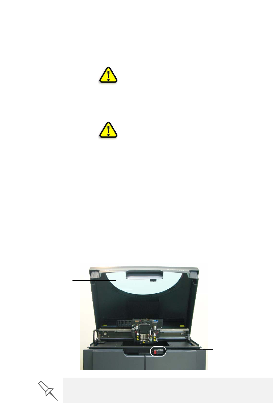
UVscreenThetransparentsectionofthecoverblocks
harmfulUVradiation,allowingtheoperatorto
viewthemodelasitisbeingmade.
Circuitbreaker Thepowertotheprinteristurnedoffincaseof
electricalovercurrent.
Note: The circuit breaker is only accessible to
service personnel.
Groundedchassis Thechassisoftheprinterisgrounded,to
preventelectricalshock.
Note: The power outlet must be properly
grounded, in accordance with the local
electric code, to provide this protection.
UV screen
Cover interlock switch
If the Objet 3-D printing system is not used as specified in this guide, the
safety features may not provide adequate protection.
DOC-07000 Rev. A 2–3
Objet500 - Connex 3 User Guide
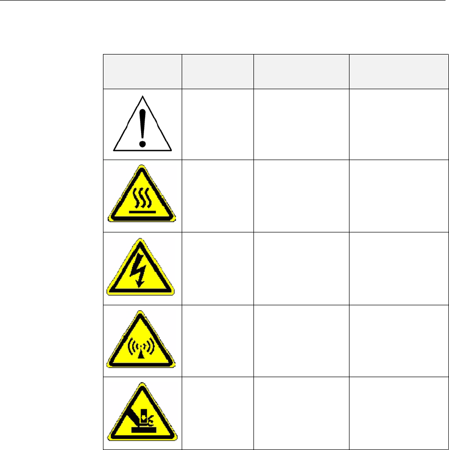
Symbols and Warning Labels
ThisfollowingtableliststhewarninglabelslocatedonorinObjetprinters.
Warning
Symbol Meaning Location Comments
Hazard
(general) Onthenameplate
onthebackofthe
printer.
Readtheinstructions
inthisdocument
beforeoperatingthe
printer.
HotsurfaceOntheprint‐head
block. Riskofburns.Donot
touchthissurface
afterprinting.
HighvoltageNeartheUVlamp
connectors.
Nearthepower‐
supplyenclosures.
Riskofelectricshock.
Ultraviolet
radiation NeartheUVlamps. Riskofinjuryfrom
ultravioletradiation.
Movingparts Onthepanelvisible
whenyouopenthe
frontdoorsofthe
printer.
Riskofinjuryfrom
movingparts.

Safety
2–4
DOC-07000 Rev. A
Safety Guidelines
Thefollowinggeneralguidelines,togetherwiththeinstructionsprovided
throughoutthisuserguide,ensureusersafetywhileoperatingand
maintainingtheObjetsystem.Ifthesystemisnotoperatedasspecified,
theuserʹssafetymaybecompromised!
Printer
Installation ¾Installationandremovaloftheprintershouldonlybedonebyqualified
servicepersonnel.
¾Connecttheprintertotheelectricoutletusingapowercordthatis
safety‐certified.
¾Theelectricoutletshouldbeeasilyaccessible,neartheprinter.
¾Neverconnectthepowerplugtoanoutletthatdoesnothaveaground
(earth)wire,andneverdisconnecttheground.Doingsomightexpose
theoperatortoseriousdangerfromelectricshock.
¾Leaveaminimumofcentimetersbetweenventilationopeningsand
wallsorotherobjects.
Printer
Operation ¾TheprintershouldonlybeoperatedbypersonstrainedbyanObjet
customer‐supportrepresentative.
¾Allpersonneloperatingormaintainingtheprintershouldknowthe
locationoffirstaidandemergencyequipmentandhowtouseit.Never
blockaccesstothisequipment!
¾Keepfingersandotherbodypartsclearoftheprintercoverwhen
closingit.
¾Neverattempttoopenthemaincoveroftheprinterwhileitisworking!
¾Neveroverridetheinterlocksafetyswitch!
¾Iftheinterlocksafetyswitcheverfails,donotusetheprinter.
¾Severalpartsoftheprinterremainextremelyhotevenafterithas
stoppedoperating.AvoidtouchingtheUVlampsandtheprintblock.
UV Radiation TheUVlampsusedintheprinteremitdangerousradiation.
¾IftheUVlampsremainonwhentheprintercoverisopen,donotstare
directlyattheUVlight.ShutdowntheprinterandcallyourObjet
serviceprovider.
Printer
Maintenance ¾Serviceoperationsshouldbeperformedonlybyqualifiedpersonnel
whohavebeeninstructedinrelevantsafetyprecautions.
¾Notifyco‐workersandthosewhohaveaccesstotheObjetsystem
beforebeginningnon‐routineandhazardouswork.
Report any potential dangers and safety-related accidents to your safety
officer or to other appropriate authorities.

DOC-07000 Rev. A 2–5
Objet500 - Connex 3 User Guide
Model and
Support
Materials
Modelandsupportmaterialsaremadeofchemicalsubstances.Although
precautionsmustbetakenwhenhandlingthesematerialsdirectly,all
modelandsupportmaterialsusedbytheObjetsystemarehandledin
sealedcartridges.Normally,operatorsoftheprintershouldneverbe
directlyexposedtohazardousmaterials.Intheunlikelyeventofaleakor
spill,followtheinstructionsthatareincludedwiththeprinting‐material
cartridgeused.
¾Storecartridgesofmodelandsupportmaterialsindoors,inadryarea
withadequateventilation,between16‐27degreesCelsius(60‐81
degreesFahrenheit).Neverexposethemtoflames,heat,sparks,or
directsunlight.
¾Keepmodelandsupportmaterialsawayfromareaswherefoodand
drinkarestored,preparedandconsumed.
¾Uncuredprintingmaterialisconsideredahazardoussubstance,
requiringcertainprecautionswhendirectlyhandlingit.Topreventskin
irritation,wearneopreneornitrilegloves.Ifthereisanychancethat
modelandsupportmaterialsmightsplashintotheeyes,wearsafety
goggles.Prolongeddirectcontactwithprintingmaterialscancausean
allergicreaction.
¾WhenhandlingUV‐curedmodelsthatmaynotbecompletelycuredon
thesurface,commonlatexglovesareadequate.
¾Topreventrespiratoryirritation,ventilateareaswheremodeland
supportmaterialsareused.Theventilationsystemshouldtotally
replacetheairatleast20timesperhour.
¾Cleanupmodel‐materialandsupport‐materialspillswithdisposable
towelsorotherabsorbent,non‐reusablematerial,suchassawdustor
activatedcharcoal.Rinsethespillareawithdenaturedorisopropyl
alcohol(IPA),followedbysoapandwater.Disposeoftheabsorbent
materialinaccordancewithlocalregulations.
¾Donotwashcontaminatedclothingathome;clothingshouldbe
professionallylaundered.
¾Disposeofcontaminatedshoes,beltsandotherleatheritemsin
accordancewithanyapplicableregulations.Absorbedprinting
materialmayre‐exposetheuserwhentheseitemsareworn.

Safety
2–6
DOC-07000 Rev. A
First Aid for Working with Printing Materials
Ingeneral,trytoavoiddirectcontactwithuncuredprintingmaterial.If
skinoreyescomeintocontactwithit,washtheareaimmediatelyand
thoroughlywithwater,andfollowthesefirst‐aidinstructions.
Contact with
Skin Ifuncuredprintingmaterialcomesincontactwithskin,washtheaffected
areaimmediatelyandthoroughlywithsoapandcoolwater,thenremove
contaminatedclothing.Payparticularattentiontoflushingthehair,ears,
noseandotherpartsofthebodythatarenoteasilycleaned.
¾Usecoolwatertopreventskinporesfromopening,sothattheliquid
materialdoesnoteasilypenetratetheskin.
¾Donotusesolventstocleanskin.
¾Iflargeareasofskinhavebeenexposed,orifprolongedcontactresults
inblisters,seekmedicalattention.Inanycase,ifirritationpersists,seek
medicalattention.
¾Avoidtheaccidentaltransferofprintingmaterialfromthehandsto
otherareasofthebody,especiallytotheeyes.
¾Ifprotectivecreamwasused,donotreapplyituntiltheskinhasbeen
completelycleansed.
Contact with
Eyes Ifuncuredprintingmaterialcomesincontactwiththeeyes,flush
immediatelywithlargeamountsofwaterfor15minutesandseekmedical
attention.
¾Avoidsunlight,fluorescentlight,andothersourcesofultraviolet
radiation.
Thewearingofcontactlenseswhenhandlingliquidprintingmaterialsis
notrecommended.Iftheliquidsplashesintotheeyeswhencontactlenses
areworn,immediatelyremovethelensesandflushtheeyeswithwater.
¾Cleananddisinfectthecontaminatedlenses.
¾Donotwearcontactlensesuntileyeirritationdisappears.
Ingestion Ifprintingmaterialisswallowed,refertotheinstructionsincludedwiththe
cartridge.Seekmedicalattentionimmediately.
Inhalation Vaporsfromprintingmaterialscanbeirritatingtotherespiratorysystem.
Ifrespiratoryirritationoccurs,exposethevictimtofreshairimmediately.
¾Ifthevictimhasstoppedbreathing,performartificialrespirationor
cardiopulmonaryresuscitation.
¾Seekmedicalattentionimmediately.
¾Keepthepatientwarmbutnothot.
¾Neverfeedanythingbymouthtoanunconsciousperson.
¾Oxygenshouldbeadministeredbyauthorizedpersonnelonly.

DOC-07000 Rev. A 2–7
Objet500 - Connex 3 User Guide
Waste Disposal
Fullycuredprintedmodelscanbedisposedofasordinaryofficetrash.
However,specialcareisrequiredwhenhandlingprinterwaste.
¾WhenremovingthewastecontainerfromtheObjetprinter,wear
neopreneornitrilegloves.
¾Topreventliquidwastefromsplashingintotheeyes,wearsafety
goggles.
¾LiquidwastefromtheObjetprinterisclassifiedashazardousindustrial
waste.Therefore,printing‐materialwastemustbepackagedand
disposedofinamannerthatpreventshumancontactwithitand
contaminationofwatersources.
¾Emptymodel‐materialandsupport‐materialcartridgescontainresidue
oftheircontents.Someleakageofthisresiduemayoccurthroughthe
brokencartridgeseal.Therefore,handleandstoreemptycartridges
withcare.
¾Donotattempttoreuseemptycartridges,anddonotpuncturethem.
¾Disposeofusedcartridgesandwastecontainersinaccordancewith
localregulations.
¾Discardcontaminatedclothing,shoes,emptycontainers,etc.,in
accordancewithanyapplicableregulations.

Safety
2–8
DOC-07000 Rev. A

DOC-07000 Rev. A 3–1
Introducing the
Objet 3-D Printing System
WorkConfigurations .......................................................................... 3
SourceFiles........................................................................................... 4
STLFiles ................................................................................................. 4
SLCFiles ................................................................................................. 4
PrintingMaterials................................................................................ 4
Storage .................................................................................................... 5
ShelfLife................................................................................................. 5
ExposuretoLight.................................................................................. 5
SafetyConsiderations........................................................................... 5
Disposal .................................................................................................. 5
WorkEnvironment.............................................................................. 6
WorkstationRequirements ................................................................ 7
PreparingFilesforUsewithObjet3‐DPrintingSystems ............. 8
ConvertingCADFilestoSTLFormat ................................................ 8
ConvertingFilestoSLCFormat.......................................................... 8
ObjetStudioSoftware ......................................................................... 9

Introducing the Objet 3-D Printing System
3–2 DOC-07000 Rev. A
Welcome to Connex
TheadvancedcapabilitiesoftheObjet3‐Dprintingsystemaremade
possiblebyPolyJetMatrix™technology,speciallydevelopedbyObjetfor
printingmodelssimultaneouslywithdifferentmodelmaterials.Forthe
firsttime,youcanachievethefollowingresultswhenprinting3‐Dmodels:
•Youcanpreparemodelsforprintingwithdesignatedmodelmaterials
andthenprintthem—usingtwoorthreebasicmodelmaterialsloaded
intheprinter,orcombinationsofthesematerials(digitalmaterials).
•Partsofthesamemodelcanbemade—simultaneously—fromdifferent
materials.
•Modelsmadefromdigitalmaterialscanhaveuniquephysical
properties,dependingonthematerialsused.
•Youcanprintobjectsthathavea“coating”madefromadifferent
materialthanthemainpartoftheobject.
Inaddition,becauseObjetprinterscanbeloadedwithtwodifferent
materials,andcanprintsimultaneouslywithcombinationsofthem,you
canstreamlineandeconomizetheprocessofproducingmodels:
•Youcanprintmodelsmadefromdifferent(single)materialsonthe
samebuildtray(“mixedtray”),inthesameprintjob.Thiseliminates
thetime‐consumingneedandexpenseofloadinganothermaterial,
flushingthesystem,andsendingaseparatejobtobeprinted.
•Youcanquicklyalternateprintingjobswithanyofthemodelmaterials
loaded—orwithmaterialcombinations—again,withouttheneedand
expenseofreplacingmaterials.
TheObjetsystemalsoenablesyoutosplitmodelsintocomponentparts
(“shells”)soyoucanisolate,manipulateandprintpartsofamodel.
However,youhaveultimatecontrolwhenseparatingmodelsintoshellsby
preparingstlfileswithyourCADsoftware.Then,withObjetsoftware,you
canassignmodelmaterialsandothercharacteristicstotheshells.
Figure 3-1: The 3-D Printer
DOC-07000 Rev. A 3–3
Objet500 - Connex 3 User Guide
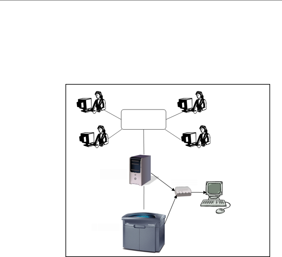
Work Configurations
The3‐Dprintingsystemcanbesetupasasingle‐stationsystemorasa
multi‐stationsystem.Whenconnectedtoalocalcomputernetwork,the
systemcanservemultipleusers.Insuchconfigurations,eachuser
workstation(client)preparesfileswithObjetStudiosoftwarefor
production.Aserver(host),typicallynexttothe3‐Dprinter,actsasajob
managerthatsendsproductionjobstotheprinterforproduction.
Figure 3‐2showstheprintersetupinamulti‐clientconfiguration.
Figure 3-2: Multi-client network configuration
WheninstallingtheObjetsoftware,youchoosewhethertoinstallitasa
clientstationorasamasterstation(serverorstandalonestation).
TheObjetsoftwarearrangesthejobsitreceivesaccordingtotheirpriorities,
model‐materialtype,andotherfactors.Inmulti‐workstation
configurations,theoperatoroftheserver—typicallytheproduction
administrator—hastotalcontroloverthejobssenttothe3‐Dprinter,and
canprioritizeanddeletejobs,reviewjobhistoryandreprintajob,andso
on.
Objet server
Objet printer
KVM switch
Client
workstations
Printer
workstation

Introducing the Objet 3-D Printing System
3–4 DOC-07000 Rev. A
Source Files
Objet3‐Dprintingsystemsproducethree‐dimensionalmodelsdesigned
withmost3‐DCADtoolsandwithotherjob‐specific3‐Dapplications.
Objetsystemsaccept:
•STLFiles
•SLCFiles
Objetsystemsfeaturethecapabilityofproducingbothtypesofmodelfiles
simultaneously.
STL Files STLisshortforStandardTriangulationLanguage.Thislanguageviewsany
objectasacollectionofsurfaces,anddescribeseachsurfaceoftheobjectas
acollectionoftriangles.
Forexample,asquarecanbedescribedastwotriangles;acube(six
squares)as12triangles.Curvedsurfacesneedmoretrianglestodescribe
them.Thehigherthetolerance(forsmoothsurfaces),themoretrianglesare
needed.Theresultisthathigh‐qualityobjectdescriptionsmeanveryheavy
files.
MostCADsoftwarecanexportSTLfiles.TheObjetsystemutilizesthese
filesforbuildingmodels(rapidprototyping),andalsofordirectlymaking
moldsformass‐producingitems.
STLfilesareASCII(text)files.Thecontentofeachfilebeginswith“solid”
andendswith“end‐solid”(bothlowercase).Betweenthesekeywordsisa
listofthetrianglesthatdescribesthefacesofthesolidmodel.Eachtriangle
definesasinglenormalvectordirectedawayfromthesolid’ssurface,
followedbyitsX‐Y‐Zcoordinates.TheseareexpressedasCartesian
coordinatesandarefloating‐pointvalues.Thecoordinatesofalltriangles
shouldbepositiveandshouldfallwithinthevolumeofthemodel.
SLC Files SLCisshortforStereo‐LithographyContour.SLCfilesdescribetwo‐
dimensionalcontoursofthethree‐dimensionalmodels.Thesecontourlines
arepolylines.
SLCfilesareASCII(text)filesthatsavemodelsasaseriesofslices.This
meansthatmodelsbasedonSLCfilescannotbeorientated;onlytheirscale
(size)andpositiononthebuildtraycanbecontrolled.Forthisreason,the
model’sorientationmustbesuitableforproductionbeforeitissavedasan
SLCfile.BecauseofthenatureofSLCfiles,theappearanceofmodelsin
ObjetStudiomaybedifferentthanthesolid‐objectimagesdisplayedfrom
STLfiles.
Printing Materials
Objetprintersproducemodelsbyjettingthinlayersofprintingmaterials
onthebuildtray,untilthecompletemodelisformed.Twotypesofmaterial
areusedinthisprocess:
•Modelmaterial—whichmakesupthefinishedmodel
•Supportmaterial—whichfillsgapsandspacesinthemodelduring
printing,andisremovedafterprinting

DOC-07000 Rev. A 3–5
Objet500 - Connex 3 User Guide
Storage MaterialsusedforprintingmodelswithObjetprintersaremadeofresins,
whicharecomposedofreactivemonomersandoligomers.Although
printingmaterialsaresuppliedinsealed,UV‐proofcartridges,caremustbe
takenwhenstoringandhandlingthem.Followtheseguidelinestoprotect
operatorsandtheenvironment,andtoensureoptimumresults.
•Toensureproductstability,donotallowthesematerialstocomeinto
contactwithmetal.Plasticsmadefrommonomer‐solublesubstances
(suchaspolystyreneorpolyvinylchloride)arenotsuitableforstoring
Objetprintingmaterials.
•Whennotinuse,keepmaterialcartridgestightlysealedtoprevent
contamination,theeffectsofexposuretoUVradiation,andaccidental
spillage.
•Storematerialcartridgesindoors,inadryareawithadequate
ventilation,between16–27degreesCelsius(60–81degreesFahrenheit).
Ifexposedtoheatorflames,cartridgesmayburstorignite.
•Signsofprematurepolymerizationinmaterialcartridgesmayinclude
bulging,leaking,theemissionofheat,andunusualodor.Exposureto
heatcancauseresintogelinthecartridge.
•Makesurethatmaterialcartridgesarestoredinaccordancewithall
localregulationsandotherapplicablerequirements.
Shelf Life Materialsusedforproducingmodelshavealimitedshelflife.Theexpiry
dateonthelabelisvalidwhenproperlystoredinanundamaged,
unopenedcartridge.Alwaysrotateyourstock,sothatthecartridgewith
theearliestdateisusedfirst.
Exposure to
Light Ifprintingmaterialsarenotintheirsealedcartridges,makesuretoshield
themfromsunlightandothersourcesofUVradiation,suchasfluorescent
andmercury‐vaporlights.ExposuretoUVradiationcausesanincreasein
viscosityand,eventually,solidification.
Safety
Considerations Beforebeingcured,resinsarehazardousmaterials.Topreventpossible
healthhazards,followtheseprecautionsregardingprintingmaterials:
•Donotexposetoflames,heatorsparks.
•Preventcontactwithskinandeyes.
•Ventilateareaswheretheyarehandled.
•Keepthemseparatefromfoodanddrink.
Curedplasticparts,however,aresafe.Theycanbehandledandstored
withoutprecautions.
Disposal DisposeofcartridgesofObjetmodelandsupportmaterialinaccordance
withallapplicablelawsandregulations.Ifnecessary,thecartridgescanbe
disassembledforrecycling.
You can find more safety information about resins in “Safety Guidelines” on
page 2-4, and “First Aid for Working with Printing Materials” on page 2-6.

Introducing the Objet 3-D Printing System
3–6 DOC-07000 Rev. A
Work Environment
Extremeheatandhumidityconditionscanadverselyaffecttheoperationof
theObjet3‐Dprinter.Therefore,itisrecommendedthatyouuseventilation
orair‐conditioningsystems,ifnecessary,tokeeptheworkareawithinthe
followingranges:
•18°–°C(64°–°F)
•30%–70%relativehumidity

DOC-07000 Rev. A 3–7
Objet500 - Connex 3 User Guide
Workstation Requirements
Thefollowingtableslisttherequirementsforcomputercomponentsused
withObjet3‐Dprintersoftware.
Requirement
Computer Type Server workstation:
Standard desktop computer (not a portable computer)
Mouse/Keyboard
Connection Server workstation:
USB, PS/2, or RS-232 (wireless components unacceptable)
Processor Intel® Core™ i3 or better
Operating System
Windows® 7 64-bit1
Professional, Ultimate, Enterprise, Starter, Home Basic,
Home Premium editions
Graphics Card2
Open GL® with 1 GB of memory or more
For dental applications:
• ATI™ Radeon™ HD 5970, with 2 GB of memory, or
• NVIDIA® GeForce® GTX 285, with 2 GB of memory
RAM 8 GB or more1
CD Drive IDE CD ROM
Hard-Disk Drive 80 GB or larger
Network Card LAN TCP/IP
(2 for server workstation; 1 for client workstation)
Video Card Server workstation: VGA connector3
Monitor Resolution: optimum for screen used
Color quality: 32 bit
Monitor Cable VGA connector3
1. On64‐bitoperatingsystems,ObjetStudiorunsasa32‐bitapplication,butitcan
utilizeupto8GBofmemory.
2. ThefollowinggraphicscardsweretestedinObjetlabs:
•NVIDIA®Quadro®Family—FX570,FX1700
•NVIDIA®GeForce®Family—6200TurboCache™,7300GT
•Intel®ExpressChipset—82915G/82915GV/82910GL,Q965/Q963,Q35,
Q45/Q43,82852/82855
•ATI®displayadapter—Radeon™HD5670,Radeon™E6760
3. TheKVMswitchrequiresVGAvideoconnections.Iftheserverworkstation
hasaDVIvideoconnector,aVGAadapterisneeded.Thecablefromthe
monitormusthaveaVGAconnector.
Note: You control both the built-in printer computer and the server workstation
with same keyboard-monitor-mouse set by using a KVM switchbox.

Introducing the Objet 3-D Printing System
3–8 DOC-07000 Rev. A
Preparing Files for Use with Objet 3-D Printing Systems
BeforeusingfileswithObjet3‐Dprintingsystems,youmustconvertthem
inyourCADprogramtoeitherSTLfilesorSLCfiles.(Foranexplanationof
thesefileformats,see“SourceFiles”onpage 3‐4.)
Afterconvertingthemodelfiles,itisrecommendedthatyoucheckthemfor
defectsinanSTL‐repairapplication(suchasMagics,byMaterialise)before
openingtheminObjetStudioandproducingthemodel.
Converting
CAD Files to
STL Format
Thisproceduremayvaryslightly,dependingontheCADsoftwareused,
butthefollowinginstructionsgenerallyapply.
To convert a file to STL format (in a CAD program):
1. FromtheFilemenu,selectSave As.
2. IntheSaveAsdialogbox,opentheSaveAsTypepull‐downmenuand
select*.STL.
3. ClickOptionsandsetthefollowingparameters:
•TotalQuality—approximately0.1mm(deviationtolerance/linear‐
dimensiontolerance)
•DetailQuality—approximately4°(angletolerance)
Note: Lowering these values produces more accurate models, but
results in larger files and longer loading and processing times. For this
reason, it is generally not recommended that you use lower values.
4. Inthefileformatoption,choosebinaryorASCII.(Bothbinaryand
ASCIIformatscanbeusedinObjetStudio.However,binaryfilesare
smaller,sothisoptionisrecommended.)
5. ClickOKorSave.
Converting
Files to SLC
Format
WhenconvertingfilestoSLCformat,itisrecommendedthatyousetalayer
thicknessof15microns(0.015mm).SinceSLCfilescannotbeorientatedin
ObjetStudio,itisimportantthatmodelsareproperlyorientatedbefore
beingsavedasSLCfiles.Considerationsforsuitablemodelorientationare
explainedin“ModelOrientation”onpage 5‐32.

DOC-07000 Rev. A 3–9
Objet500 - Connex 3 User Guide
Objet Studio Software
ObjetStudiosoftwarefortheObjet3‐Dprintingsystemconsistsoftwo
mainscreens:
•TraySettings/ModelSettings
•JobManager
Tray Settings / Model Settings
IntheTraySettingsandModelSettingsscreens,youpreparesourcefilesfor
productioninObjet3‐Dprinters.ObjetStudiooffersyouawidevarietyof
file‐preparationoptions,butalwaysconsistsofthefollowingbasic
procedure:
1. Insertingoneormoreobjectsonthebuildtray
2. Positioningtheobject(s)onthetray
3. Configuringobjectandtrayparameters
4. Savingthetrayconfigurationasanobjtf(ObjetTrayFormat)file
5. SendingtheobjtffiletotheObjet3‐Dprinterforproduction
UsingObjetStudiotoperformthesetasksisdescribedindetailinchapter 5,
“UsingObjetStudio.”
Job Manager
TheJobManagerscreenisdifferentforclientworkstationsandforthe
computerconnecteddirectlytotheObjet3‐Dprinter.
•InObjetStudioinstalledonthedirectly‐connectedcomputer(server),
theJobManagerscreendisplaysthequeueandstatusforalljobssentto
the3‐Dprinterbytheserveritselfandbyallclientcomputersonthe
network.Alljobsdisplayedcanbeeditedandmanipulated.
•InObjetStudioinstalledonclientcomputers,theJobManagerscreen
displaysthequeueandstatusonlyforjobssenttoa3‐Dprinterserver
fromthatcomputer.Onlythesejobscanbeeditedandmanipulated
fromtheclientcomputer.
Client computers can be connected, via the local network, to different Objet
3-D printers, but only to one at a time. The Job Manager screen displays
the status of the 3-D printer to which the client is currently connected.

Introducing the Objet 3-D Printing System
3–10 DOC-07000 Rev. A

DOC-07000 Rev. A 4–1
Installing Objet Software
HowtoInstallSoftwarefortheObjet 3‐D Printing System.......... 2
Installing Objet Software
4–2
DOC-07000 Rev. A
How to Install Software for the Objet 3-D Printing System
TheObjetStudiosetupwizardguidesyouwheninstallingtheObjet
software.Duringinstallation,youmustchoosetoinstalleithertheserver
(“host”)applicationortheclientapplication.
To install Objet software:
1. InserttheObjetStudioCDintothediskdrive.
2. Right‐clicktheStartbuttonandselectExplore(oruseanyothermethod
fordisplayingfilesonthecomputer).
3. OpentheCD‐drivefolderandselectSetup.
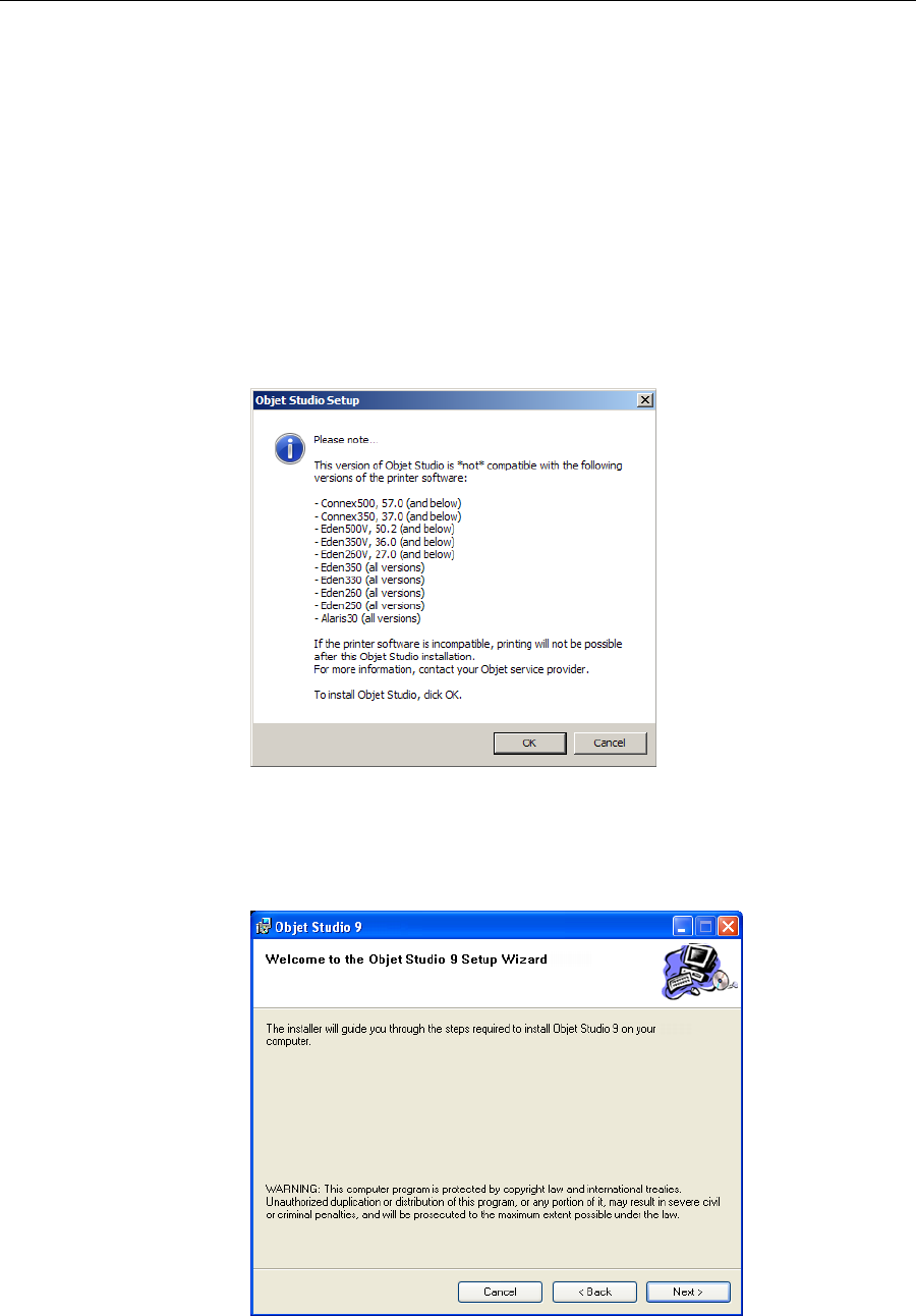
4. IfyouareinstallinganObjetStudioupgrade,makesurethatyour
printeriscompatiblewithitbycheckingthelistdisplayed.
Figure 4-3: Objet Studio compatibility check
5. ToinstallObjetStudio,youmustagreetothelicenseagreement.After
readingitsterms,clickYestocontinue,orNotoclosethewizard.
IfyouclickYes,thefollowingscreenshouldappear.
Figure 4-1:Objet Studio installation wizard—Welcome screen
6. ClickNexttobegininstallation.
DOC-07000 Rev. A 4–3
Objet500 - Connex 3 User Guide
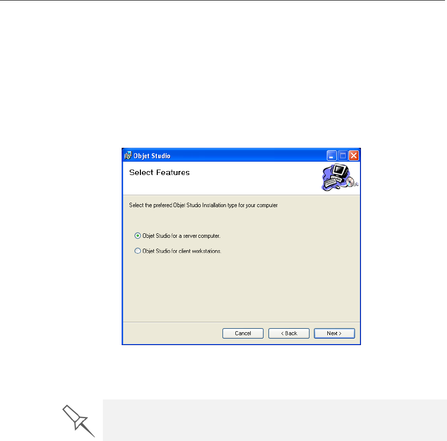
7. IntheSelectFeaturesscreen,selecttherequiredinstallationoption.
SelectObjet Studio for a server computer...
•ifyouareinstallingObjetStudioonaserver(“host”)computer—
thecomputerdirectlyconnectedtoanObjetprinter.
•ifyouareinstallingObjetStudioonastandalone(off‐line)
computer.
SelectObjet Studio for client workstations ifyouareinstallingObjet
Studioona“client”workstation—aremotecomputerthatprepares
printjobsandthensendsthemtoaservercomputer.
Figure 4-2: Objet Studio configuration selection
8. IntheSelectInstallationFolderscreen,verifythedestinationfolderand
clickNext.
It is recommended that you do not change the default destination folder.
Click Disk Space to check the space in the destination folder.
Installing Objet Software
4–4
DOC-07000 Rev. A
Figure 4-3: Objet Studio installation-folder selection
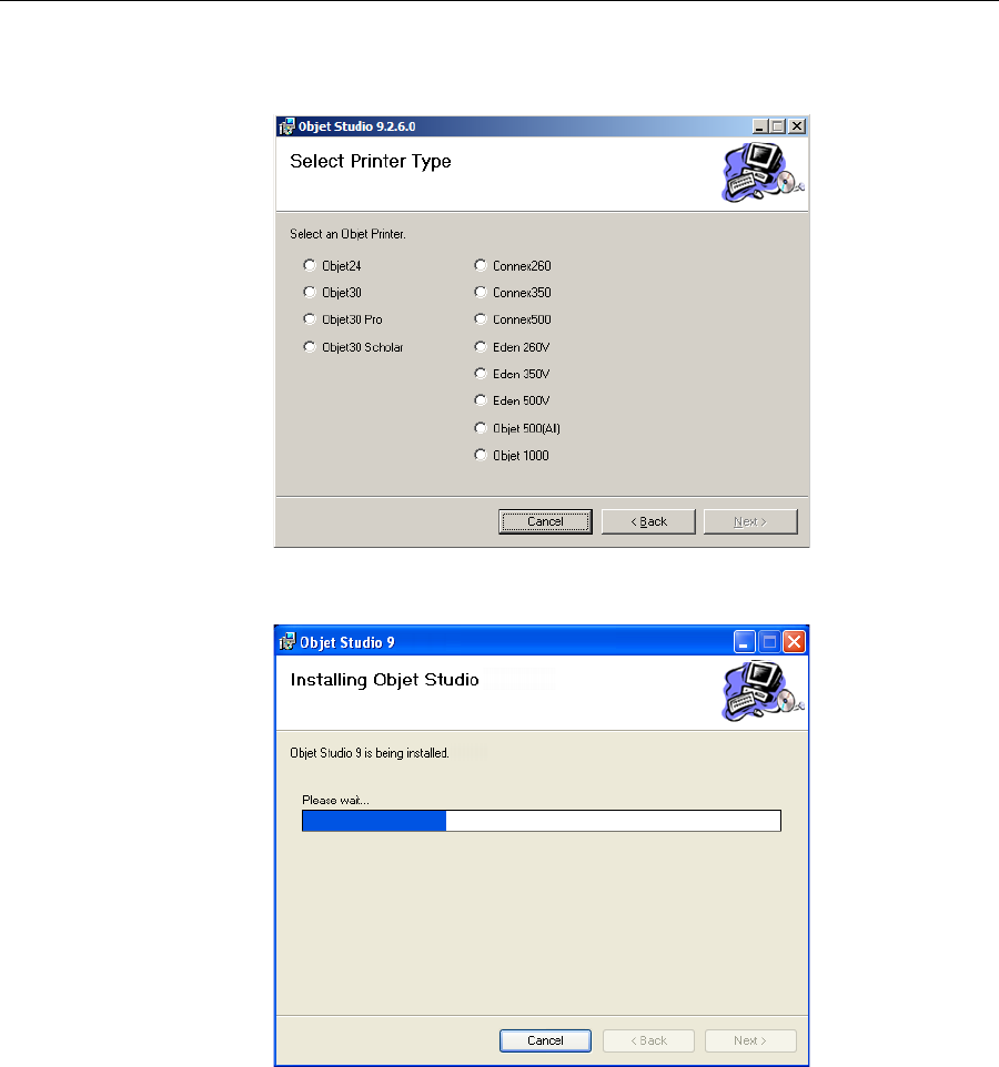
9. IntheConfirmInstallationscreen,clickNext tobegininstallation.
Installationbeginsandaprogressbarappears,showingtheprogressof
theinstallationprocess.
Figure 4-4: Installation progress bar
DOC-07000 Rev. A 4–5
Objet500 - Connex 3 User Guide
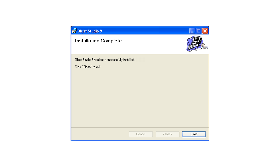
WhentheObjetprograminstallationiscomplete,thefinalInstallShield
Wizardscreenappears.
Figure 4-5: Final installation screen
Sometimes,youmustrestartthecomputertocompletethesoftware
installation.Youcandosonoworatanothertime.
Note: Make sure to remove the CD from the disk drive before restarting the
computer.
Theinstallationprocessendswhentheappropriateicon(s)appearonthe
computerdesktop:
•ObjetStudio
•StopJobManager(forserversandstandalonestations)

Installing Objet Software
4–6
DOC-07000 Rev. A

DOC-07000 Rev. A 5–1
Using Objet Studio
ObjetStudioInterface ......................................................................... 3
PreparingModelsforProduction ..................................................... 7
PlacingObjectsontheBuildTray....................................................... 8
OpeningObjetTrayFiles ................................................................... 12
SplittingObjectsintoComponents................................................... 19
Model‐MaterialSettings..................................................................... 21
ChangingtheModelMaterial ........................................................... 22
DigitalMaterials.................................................................................. 23
AssigningaModelMaterialtoObjects............................................ 25
SurfaceFinish....................................................................................... 25
CoatingObjects.................................................................................... 27
AssigningPropertiestoHiddenObjects ......................................... 28
PositioningObjectsontheBuildTray ............................................ 28
ModelOrientation............................................................................. 32
ManipulatingObjectsontheBuildTray........................................ 33
GroupingandUngroupingObjects.................................................. 41
DisplayOptions................................................................................. 43
HandlingCompletedTrays ............................................................. 51
PrintingModes .................................................................................... 53
ApplyingAdditionalObjetStudioFeatures ................................. 58
DividingObjects.................................................................................. 58
ChoosingtheSupportStrength......................................................... 59
“Hollow”—FillingModelswithSupportMaterial ....................... 60
DisplayingtheCrossSectionofObjects .......................................... 61
SavingtheScreenDisplayasanImage File .................................... 62
ExportingandImportingObjetBuildTrays ................................... 63
CustomizingObjetStudio................................................................ 64
CreatingaQuickAccessToolbar ...................................................... 64
KeyboardShortcuts ............................................................................ 67
SettingUserPreferences..................................................................... 68
ProfessionalModeFeatures............................................................. 69
DefaultSettings ................................................................................... 70
OpenGLDriverConfiguration......................................................... 71
MonitoringandManagingPrintJobs ............................................ 76
JobManagerScreen ............................................................................ 76
JobManagerCommands ................................................................... 82
ConfiguringUserAlerts..................................................................... 85
PrintingtheTray.................................................................................. 86
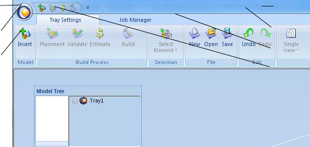
5–2
DOC-07000 Rev. A
TheObjetStudiointerfaceconsistsoftwo
mainscreens:
•TraySettings—forarrangingmodels
andpreparingthemforprinting.
Thisscreenisdescribedbelow.
•JobManager—formonitoringand
managingprintjobs.
Thisscreenisdescribedin“Monitoring
andManagingPrintJobs”onpage 76.
Eachiscontrolledbymenusandiconson
itsownribbon.Anadditionalribbon,
ModelSettings,displayscontrolsfor
configuringandmanipulatingselected
models.
ObjetStudioanticipatesyourworkflowby
displayingandenablingtheoptions
relevanttoyourcurrenttask.Forexample,
whenyoufirstopenObjetStudio,the
ModelSettingsribbonisdisableduntilyou
placeamodelonthebuildtray.Similarly,
menuoptionsavailablefromtheStandard
Toolbarmenusareenabledordisabledto
matchthecurrentworkflow.
Objet Studio
Commands
menu
Quick Access
toolbar
Model Tree
pane
Help
Standard
toolbar
Active
ribbon
Job
Manager
tab

DOC-07000 Rev. A 5–3
Objet500 - Connex 3 User Guide
Theribbon,colorsused,andseveralotherinterfacefeaturescanbe
customized.Howtochangetheappearanceoftheinterfaceisexplainedin
“CustomizingObjetStudio”onpage 64.
Using Objet Studio
5–4
DOC-07000 Rev. A
Arrange
Tray
Ribbon
Commands
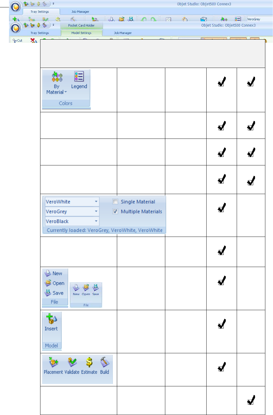
ThefollowingtableliststheTraySettingsandModelSettingsribbon
commandgroups,andshowswhentheyareenabled,andwherethey
appear.
Group Purpose When
enabled Tray
Settings
Ribbon
Model
Settings
Ribbon
Settingdisplay
colors. Always.
Selecting
perspectiveand
zoomlevel.
Modelsareon
thebuildtray.
Choosetoselect
aplane. Modelsareon
thebuildtray.
Changethe
perspectiveof
theactivepane.
Modelsareon
thebuildtray.
Assigningmodel
material. •Buildtray
isempty.
•Modelsare
not
selected.
Undoingor
redoingactions. Afteran
actionor
object
selection.
Openingand
savingfiles. Modelsare
notselected.
Placingmodel
filesonthebuild
tray.
Always.
Pre‐build/build
commands. Modelsareon
thebuildtray.
Settingmodel
dimensions. Amodelis
selected.
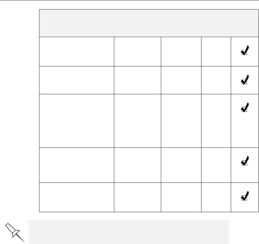
DOC-07000 Rev. A 5–5
Objet500 - Connex 3 User Guide
Cutting,
copying,pasting
anddeleting
models.
Amodelis
selected.
Moving,rotating
andresizing
models.
Amodelis
selected.
•Assigninga
materialtoa
modelor
shell.
•Separatinga
modelinto
shells.
Amodelis
selected.
Assigningmodel
finishand
settingsupport
strength/
“hollow.”
Amodelis
selected.
Settingamodel’s
unitofmeasure
(millimetersor
inches).
Amodelis
selected.
Group Purpose When
enabled Tray
Settings
Ribbon
Model
Settings
Ribbon
To quickly identify an icon, move the cursor over the icon to display its
tooltip. The “Undo” and “Redo” tooltips change to reflect your last Objet
Studio action.
Using Objet Studio
5–6
DOC-07000 Rev. A
Objet Studio
Commands
Menu
ClickingtheObjeticon(intheupper‐leftcorner)openstheObjetStudio
Commandsmenu.Thismenudisplaysbasicapplicationcommandsand
options.
TheOptions buttonopensadialogboxforcustomizingObjetStudio.
TheModelTreepaneliststheobjectsplacedonthebuildtrayinaparent‐
childhierarchy.Bydefault,thepane“floats”—thatis,youcanmoveitto
anotherpositiononthescreenandresizeit.Alternatively,youcanfixits
positionattheleftoftheapplicationwindow,andevenhideit.

DOC-07000 Rev. A 5–7
Objet500 - Connex 3 User Guide
Preparing Models for Production
Modelpreparationinvolvesthefollowingbasicsteps:
1. Placeobjectsorassembliesonthebuildtray.
2. Ifnecessary,manipulatetheobject’sorientationandposition.
3. Selectthematerialsandmodelfinish.
JustasObjetprinterscanproducedifferentmodelsonthebuildtrayusing
differentmaterials,youcanproducecomponentsofamodelwithdifferent
materials.Todothis,eachpartofthemodelmustbeaseparatestlfile.Ifthe
model’scomponentpartswerenotsavedintheCADsoftwareasseparate
stlfiles,youcanuseObjetStudiotoseparatethemodelintocomponent
parts.(Thisisdescribedin“SplittingObjectsintoComponents”onpage 16
andin“DividingObjects”onpage 58.)
OBJDF Files:
Overview Anobjdffiledescribesboththegeometryofasingleobjectandthe
materials,andfinishrequiredtoprintit.Theobjdffilecanrepresentan
objectthatisasinglestlfile,oranobjectassembledfromcomponentstl
files.
ObjetStudioenablesyoutosplitanstlfilerepresentingacomplexobject
intoanassemblyofcomponentstlfiles,andsavetheassemblyasanobjdf
file.Eachpart(stlfile)describedbytheobjdffilecanhaveitsownmodel‐
materialcharacteristic,sothattheObjetprinterproducesthecomponent
partsfromspecificmaterials.
Anotheruseforobjdffilesisforsavingagroupofseparateobjectsonthe
buildtrayasoneunit,togetherwiththeirrelativepositionsandmaterials.
Thisisespeciallyusefulforproducingmodelsinthefuturewiththesame
materials.Infact,whenyousaveobjdffiles,youspecifymaterialsfor
printingmodelswithoutregardtothematerialcartridgesloadedinthe
printer.Thesameobjectcanlaterbeplacedonbuildtraysforprinting.Each
timeyousendabuildtraytotheprinter,youdecidewhethertoallow
printingwithsubstitutematerialsoronlywiththematerialsspecified.
TheConnexversionofObjetStudioenablesyoutodisplay,manipulateand
printcomponentpartsofamodelassemblythatwassavedasanobjdffile,
sinceeachcomponentisaseparatestlfile.Thiscanbeusefulforprinting
onlyspecificpartsofamodel.
Model Files Toproducemodels,youopenoneormoremodelfilesinObjetStudioand
positionobjectsonthebuildtray.Youcanplaceobjectsonthebuildtrayin
severalways:
•byinsertingindividual stl or slc files(oranassemblyofstlfiles).
•byinserting anobjdffile(anassembly).
•bypastingobjectsthatyoucopiedtotheWindowsclipboard.
Using Objet Studio
5–8
DOC-07000 Rev. A
Placing
Objects on the
Build Tray
To place an object on the build tray using stl, slc or files:
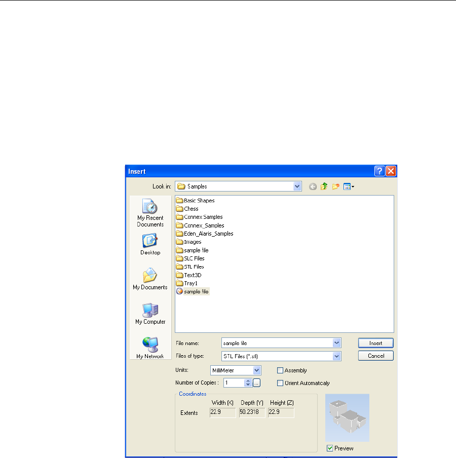
1. OpentheInsertdialogbox—
•FromtheObjectmenu,selectInsert.
or—
•OntheArrangeTrayribbon,click.
or—
•Right‐clickonthebuildtray,andselectInsert fromthecontext
menu.
TheInsertdialogboxappears.
2. IntheLookinfield,displaytheappropriatefolder.
3. IntheFilesoftypefield,selectthefiletypestodisplay(stl,slc,).
4. Selectthedesiredfile,andmakesurethatitappearsintheFilename
field.
IfthePreviewcheckboxisselected,theobjectisdisplayedinthedialog
box.
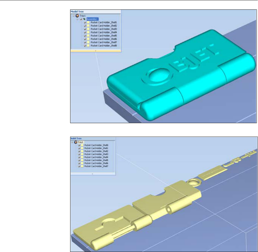
Note: You can open several stl files at once, to place several models on the
build tray. If you select multiple stl files that make up an assembly,
you can select all or some of the parts. To print the entire model,
select all of an assembly’s component stl files, and select the
Assembly check box.This positions the parts as a complete,
integrated model instead of as independent parts. The effects of
selecting the Assembly check box—in both the model tree and the
build tray display—are shown in the following figures.
DOC-07000 Rev. A 5–9
Objet500 - Connex 3 User Guide
Figure 5-7: Assembly check box selected—stl files are placed as an assembly
Figure 5-8: Assembly check box not selected—stl files are placed as parts
TheModelSettingsribbonisdisplayedwhenobjectsareplacedonthe
buildtray.
5. Selectanyofthefollowingoptions,asrequired:
•Units—Millimetersorinchesfortheobject’sunitsofmeasure.
The3‐Dfilecontainstheobjectʹsproportions,butnotitsunitsof
measure.Therefore,makesuretocorrectlyselecteithermillimeters
orincheswheninsertinganobject.Otherwise,thesizeoftheobject
onthebuildtraywillbeeithermuchtoolargeormuchtoosmall.To
changethemeasurementunitsofobjectsalreadyplacedonthetray,
see“MeasurementUnits”onpage 36.
•Number of copies—Howmanycopiesofthisobjecttoplaceonthe
buildtray.
•Orient Automatically—Automaticallyorientobjectsonthebuild
trayforefficientmodelbuilding.
•Assembly—Markthischeckboxifyouselectedmultiplestlfiles
thatarepartofanassembly.
Using Objet Studio
5–10
DOC-07000 Rev. A
Note: The Extents values displayed in the Insert dialog box’s Coordinates
field, represent the maximum dimensions of the object on each axis.
These dimensions correspond to the virtual “bounding box”
surrounding the object see figure 5-49 on page 36).
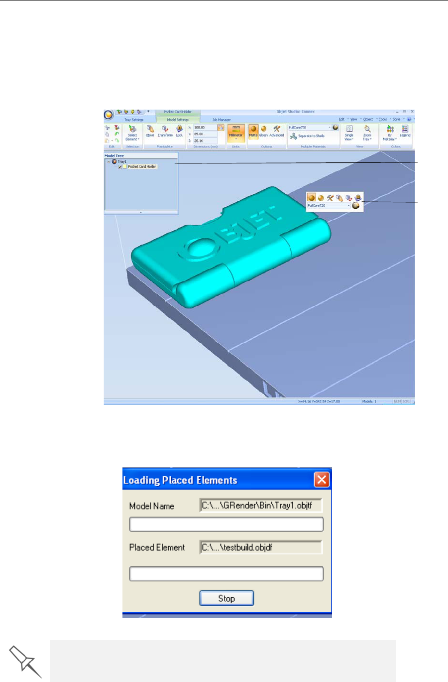
6. ClickInsert.
ObjetStudioplacestheobjectonthebuildtray,andinthemodeltree.
TheModelSettingsribbonisdisplayedwhenobjectsareplacedonthe
buildtray.
Iftheobjectisoveracertainsize,theLoadingPlacedElementsdialogbox
mayappear.
Model
Toolbar
Model
Tree
pane
You can speed up the opening of large files by changing the Large Files
settings—see “Loading Large Files” on page 48).
DOC-07000 Rev. A 5–11
Objet500 - Connex 3 User Guide
Opening files Beforeplacingfilesonthebuildtray,ObjetStudiomustextractthe
componentstlfilestogetherwithinformationabouttheirorientationand
materials.Todothis,ObjetStudiocreatesafolderwiththesamenameas
thefile,inthesamelocation.
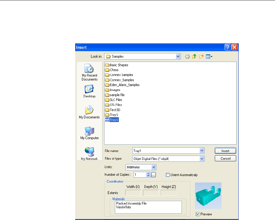
Figure 5-9: Insert dialog box ( file)
Using Objet Studio
5–12
DOC-07000 Rev. A
Opening Objet
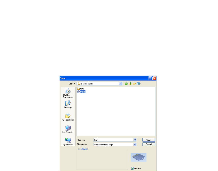
Tray Files Youcanopentraysthatweresavedasobjtffiles,forexample,atrayyou
savedwhilepreparingitforprinting,andnowyouwanttocontinue
preparingit.
To place an object saved as an Objet Tray File (objtf) file on the build
tray:
1. FromtheFilegroup,click.
or—
FromtheObjetStudioCommands,selectOpen.
TheOpendialogboxisdisplayed.
2. Selectthedesiredfile,andmakesurethatitappearsintheFilename
field.
IfthePreviewcheckboxisselected,theobjectisdisplayed.
3. ClickOpen.
ObjetStudioopensthetrayfile.
DOC-07000 Rev. A 5–13
Objet500 - Connex 3 User Guide
Stl file loading
preference Ifthereareidenticallynamedstlfilesinmorethanonelocation,youneed
toensurethatthecorrectcomponentstlfilesarelinkedtotheobjtffile.For
example,ifthereareidenticallynamedstlfilesononedriveandonaflash
drive(thiscanoccurifyoucopytheoriginalfilestoaworkingfolder),you
cansetthedefaultlocationfromwhichfilesareloaded.
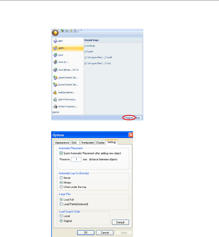
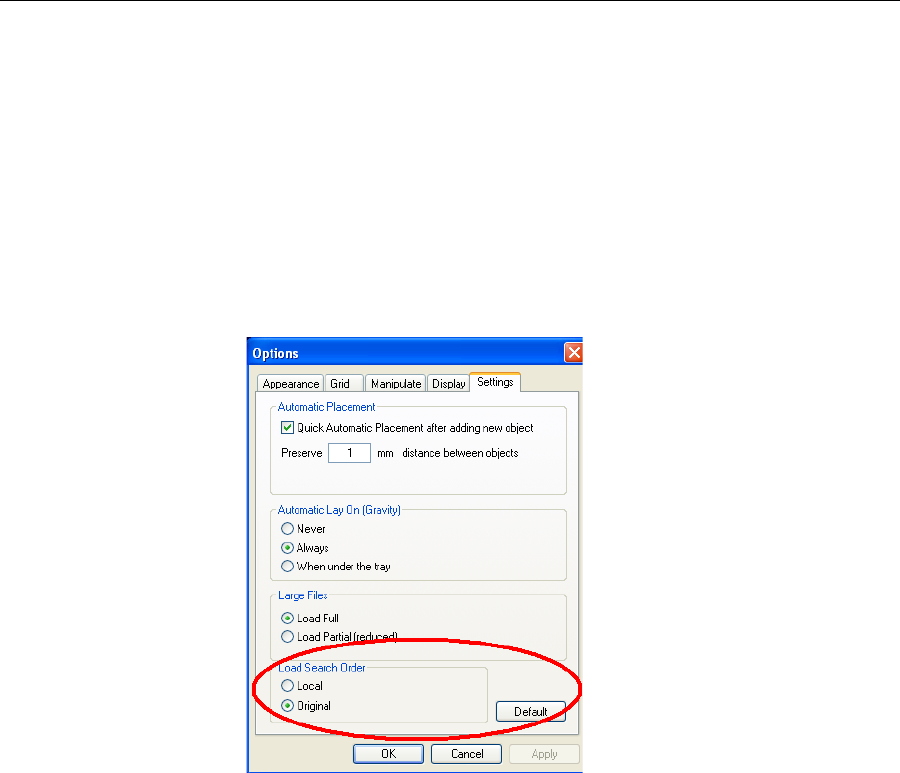
To set the Load Order:
1. FromtheToolsmenu,selectOptions.
or—
IntheObjetStudioCommandsMenu,clickOptions.
2. IntheOptionsdialogbox,displaytheSettingstab.
Figure 5-10: Options dialog box, Settings tab
3. UnderLoadSearchOrder,selectanoption:
•Local—toloadfilesfromthelocationwheretheywerelastsaved.
•Original—toloadfilesintheiroriginallocation.
4. ClickOK.
Using Objet Studio
5–14
DOC-07000 Rev. A
Quick-Access
Model
Commands
Youcanaccesscommoncommandsforworkingwithobjectsonthebuild
traywiththeconvenientModelToolbarandcontextmenus.
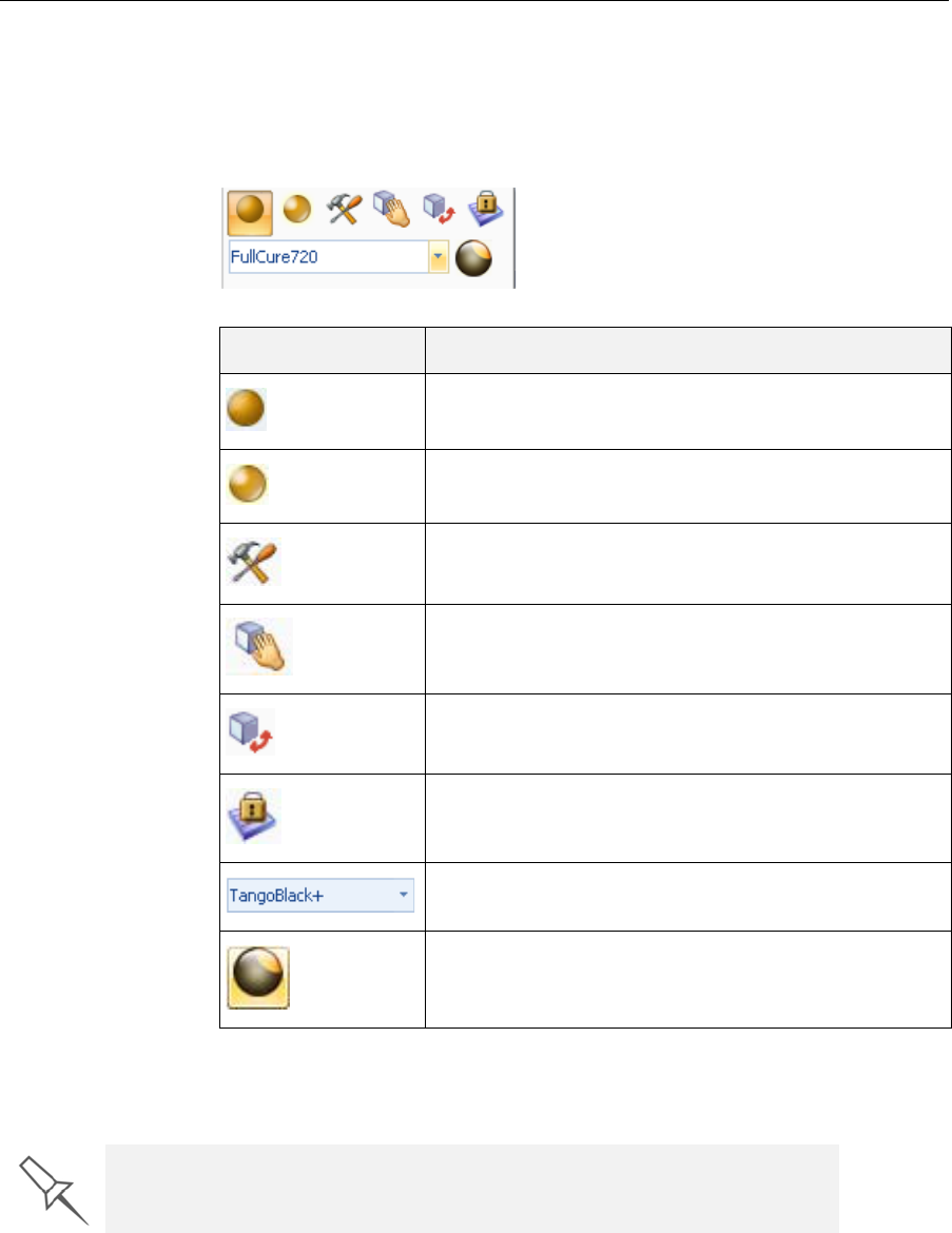
Model Toolbar SelectanobjectinthetraytodisplaytheModelToolbarthatcontainsicons
toperformcommontasks.
ThetablebelowdescribestheModelToolbaricons.
Right-click model
menu Ifyouright‐clickonanobject,apop‐upcontextmenuisdisplayedfrom
whichyoucanalsoselectthemodelfinish,changeitspositionandscale,
andsettheGridStyleandHollowoptions.
Icon Description
Appliesamattefinishtothemodel.
Appliesaglossyfinishtothemodel.
OpenstheAdvancedPropertiesdialogboxforsettingthe
GridStyleandtheHollowoption.
Enablesdragginganobject.
OpenstheTransformdialogboxforchangingthe
object’spositionandscale.
TogglestheLockModelOrientationsetting.
Allowsyoutochoosetheprintingmaterials.
Enablesyoutoapplyacoatingtothemodel,orchange
thecoatingpreviouslyapplied.
You can also create a Quick Access toolbar with your most commonly used
icons grouped together. See “Building a Quick Access Toolbar” on page 89.
DOC-07000 Rev. A 5–15
Objet500 - Connex 3 User Guide
Copying and
Pasting
Objects
Ifyouneedtoduplicateobjectsonthebuildtray,youcan,ofcourse,insert
thesameobjectfromitsfilemorethanonce.Aneasierway,however,isto
copyandpastetheobject.Youcancopyobjectsfromthebuildtrayorthe
modeltree—individualormultiplepartsorassemblies.Theobjectscopied
remainintheWindowsclipboarduntilyoupastethemontothebuildtray.
Youcanalsocopyobjectsfromonetrayandpastethemontoanother,inthe
samewayasyoucopytextfromonedocumentandpasteitintoanother
one.However,ObjetStudioallowsonlyonetraytobeopenatatime.For
eachbuildtrayyouneedtoworkwith(atthesametime),youmustopena
separateObjetStudiowindow,byrunningtheapplicationagain(fromthe
WindowsStartmenu).
YouperformtheCopyandPastecommandsasinotherWindows
applications:
•fromtheright‐clickcontextmenu.
•byusingkeyboardshortcuts(Ctrl+CandCtrl+V,respectively).
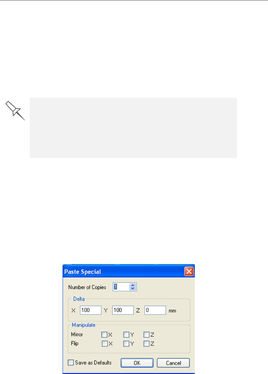
ThePasteSpecialcommand(fromtheobject’sright‐clickcontextmenu)
enablesyoutoplaceduplicateobjectsevenmoreefficiently:
•Youcanspecifythenumberofduplicatestoplaceonthebuildtrayat
once.
•Youcansetthedistance,oneachaxis,betweentheduplicateobjects.
•Youcanmanipulatemirrorimagesoftheoriginalobject,andflipthem
onselectedaxes.
Figure 5-11: Paste Special dialog box
Having multiple Objet Studio windows open can be convenient when you
need to manipulate or configure objects before inserting them in your
production build tray. For example, if you need to change the model material
of an object (saved as an objdf file) to match the model material already
used in the production build tray, you must do so before inserting the
object—on another tray. Copying and pasting also allows you to utilize
objects already configured on previously-used build trays for newer
projects.
Using Objet Studio
5–16
DOC-07000 Rev. A
Selecting
Objects Tomanipulateanobjectonthebuildtrayorassigncharacteristicstoit
(modelmaterial,buildingstyleetc.),youmustfirstselecttheobject.You
selectanobjectbyclickingit,eitheronthetrayorinthemodeltree.Its
imageonthebuildtraychangescolor(tolightblue,bydefault)andits
nameishighlightedinthemodeltree.Youcanselectmultipleobjectsby
drawingaboxaroundthemwiththemousecursor,orbypressingtheCtrl
orShiftkeyswhileclickingadditionalobjects.
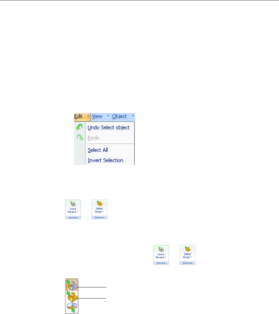
Alternatively,selectorde‐selectobjectsusingthefollowingEditmenu
commands:
•Select All
•Invert Selection
•Undo Select object
Sometimes,youneedtoselectindividualelementsofanassembly.Other
times,youneedtoselecttheentireassembly.TheSelectionicondisplayed
ontheribbondetermineswhatwillbeselectedwhenyouclickonthe
model:
or
To change the selection action:
1. OntheArrangeTrayorModelSettingsribbon—
a. ClicktheSelectionicon:or.
b. Ontheflyouttoolbar,clicktheappropriateicon:
Figure 5-12: Selection flyout toolbar
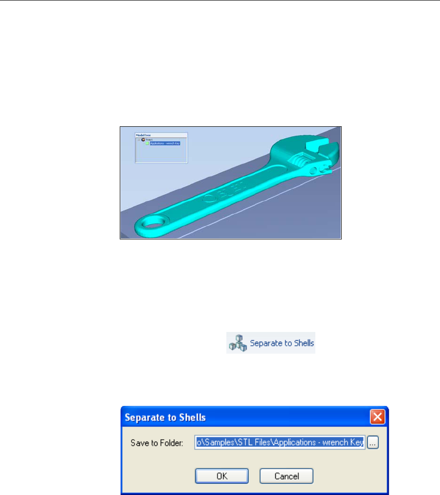
Splitting
Objects into
Components
Youcanconvertacomplexobjecttoanassemblyofcomponentparts.Todo
so,yousplitthestlfilethatrepresentstheobjectintoagroupofseparatestl
files,eachonerepresentingacomponent.(ThisisreferredtointheObjet
Studiointerfaceasseparatingtheobjectintoshells.)Youcanthenassigna
modelmaterialtoeachstlfile,andyoucansavethenewly‐created
assemblyasanobjdffile.
Select Group
Select Element
DOC-07000 Rev. A 5–17
Objet500 - Connex 3 User Guide
To split an object into an assembly of component parts:
1. Iftheobjectisnotdisplayed,placeitonthebuildtraybyinsertingitsstl
file(see“PlacingObjectsontheBuildTray”onpage 8).
Theobjectappears—onthebuildtrayandinthemodeltreepane—asa
singlepart.Itisassigned,bydefault,the“primary”modelmaterial.(If
ObjetStudioisconfiguredwithasecondarymaterial,youcanassign
it—oradigitalmaterial—totheentireobject.Thisisexplainedin
“Model‐MaterialSettings”onpage 18.)
Figure 5-13: Object placed on the build tray from a single stl file
Note: There is no need to resize or arrange the object on the build tray at
this time.
2. Withtheobjectselected:
•FromtheObjectmenu,selectSeparate into Shells.
or—
•Ontheribbon,click.
Adialogboxopensinwhichyoucanspecifywheretosavethe
componentstlfiles.(Bydefault,ObjetStudioofferstosavethenewfiles
inafolderinthesamelocationastheoriginalstlfile.)
Figure 5-14: Folder selection for saving stl files after splitting into shells
3. ClickOK.
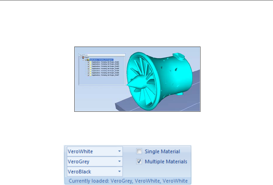
Using Objet Studio
5–18
DOC-07000 Rev. A
ObjetStudiosplitstheobjectintoanassemblyofcomponentparts,each
aseparatestlfile(“shell”).
Theobjectappears—onthebuildtrayandinthemodeltree—asan
assemblyofparts(“shells”).Youcanassigneachpartadifferentmodel
material(Thisisexplainedin“Model‐MaterialSettings”onpage 18).
Figure 5-15: Object after being converted to an assembly of component parts
Model-Material
Settings BeforeplacingobjectsonthebuildtrayinObjetStudio,youshouldpay
attentiontothematerialselectionsettingsontheArrangeTrayribbon.
Figure 5-16: Material selection settings
•Bydefault,thematerialselectionsettingsontheribboncorrespondto
thethreemodelcartridgesloadedintheprinter.
•Thematerialsdisplayedarebasicmodelmaterials.Thesematerialscan
laterbecombinedtocreatedigitalmaterials(see“DigitalMaterials”on
page 20).
•Thematerialdisplayedonthetop(VeroWhite,inthefigureabove)is
consideredtheprimarymodelmaterial(“Model‐1”).Itisassignedto
objectsthatdonothaveamaterialassignmentwhenyouplacethemon
thebuildtray.Forexample,sincestlfilesdonotcontaininformation
aboutthemodelmaterial,ObjetStudioassignstheprimarymodel
materialtothem.Also,ifyoutrytoinsertobjdffileswhoseassigned
materialsarenotrecognizedbyyourversionofObjetStudio,youcan
insertthefilebysubstitutingtheprimarymodelmaterialforthe
missingmaterials.
•SelectSingle Materialifyouwanttoprintusingonlyonematerial—all
ofthematerialdrop‐downmenuscontainthesamematerial.Ifyou
decidetoprintwithmultiplematerials,thematerialinthetopdrop‐
downmenuremainsassignedtotheobjectuntilyouselectanother
material.
•Ifyouinsertanobjdffileintoanemptybuildtray,andthemodel‐
materialassignmentdoesnotmatchthesettingsontheArrangeTray
ribbon,thesesettingsarechangedautomatically.However,ifthereisan
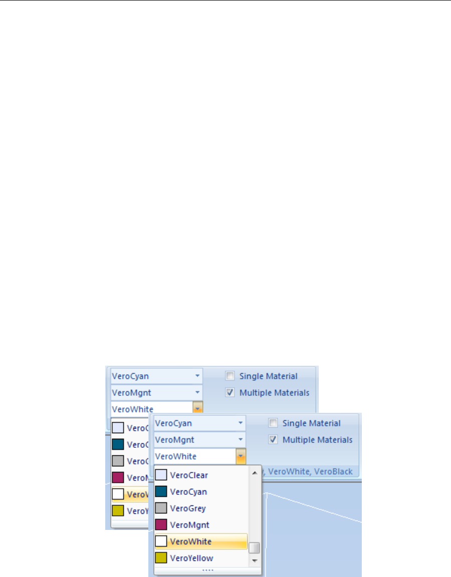
DOC-07000 Rev. A 5–19
Objet500 - Connex 3 User Guide
objectalreadyonthebuildtraywhosematerialsdonotmatchthe
materialassignmentintheobjdffile,youcannotplacethenewobjecton
thetray.Toprintthisobject,youhavethefollowingoptions:
Insteadofprintingitonthesamebuildtray,printthenewobjectasa
separatejob.
Changethematerialsassignedtoobjectsonthebuildtraytomatch
thoseassignedtothenewobject(see“ChangingtheModel
Material”and“AssigningaModelMaterialtoObjects,”below).
Changethematerialsassignedtothenewobjectbeforeinsertingit,
sothereisnoconflictwiththesettingsontheTraySettingsribbon.
To change the materials assigned to an object before inserting it:
1. OpenanotherObjetStudiowindow,byrunningtheapplicationfrom
theWindowsStartmenu.
2. Insertthenewobject(objdffile)intotheemptybuildtray.
3. ChangethematerialselectionsettingsontheTraySettingsribbonto
thoseusedontheotherbuildtray.
4. Assignmaterialstotheobject(see“AssigningaModelMaterialto
Objects”onpage 23).
5. Selecttheobjectandcopyit.
6. DisplaytheotherObjetStudiowindow,andpastetheobjectontothe
buildtray.
Note: You can save the object with the new materials either as a new objdf
file, or by saving the original file with the changes.
Figure 5-17: Whenthreedifferentmodelmaterialsappearontheribbon,
youcanproduceobjectsfromanyofthemorfromacombinationof
them—digitalmaterials.
three three
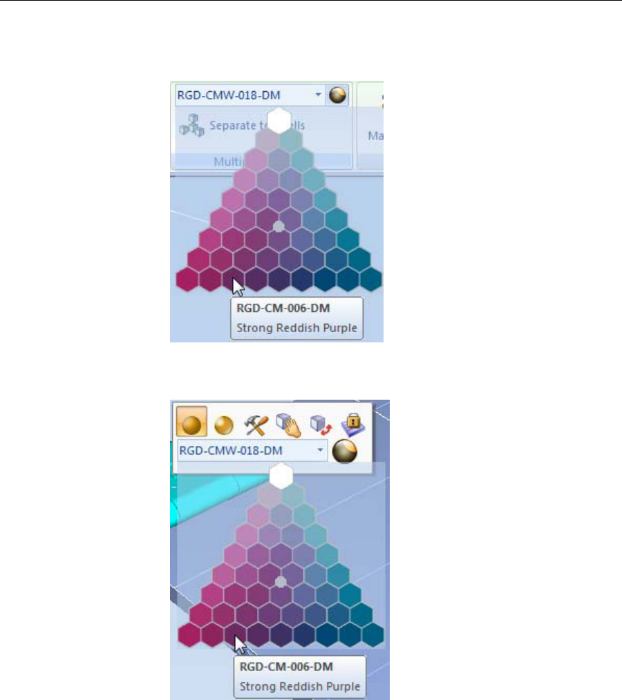
Using Objet Studio
5–20
DOC-07000 Rev. A
Color selection
pallete Youcandisplaythematerialcoloroptionsasacolorpallete.Fromthe
Toolsmenu,selectColormaterialselectionandthenSelectfromcolor
pallete.
Figure 5-18: Color selection pallete for assigning materials to objects
Figure 5-19: Color selection pallete from Model Toolbar
Note: The color selection pallete will only be displayed if one of the
following combinations of primary materials are selected:
•VeroCyanandVeroMagentaandVeroWhite
•VeroCyanandVeroMagentaandVeroYellow
•VeroCyanandVeroWhiteandVeroYellow
•VeroMgntandVeroWhiteandVeroYellow

DOC-07000 Rev. A 5–21
Objet500 - Connex 3 User Guide
Surface Finish Modelscanbeprintedwithamatteorglossysurfacefinish.Tocreatea
mattefinish,theprintersurroundsmodelswithathinlayerofsupport
material.
To set the model finish:
1. Selectthemodel.
2. SelectMatteorGlossy inoneofthefollowingplaces:
•ModelSettingsribbon,Optionsgroup
•ModelToolbar
•right‐clickcontextmenu(whenselectingthemodel)
YoucanconfigureObjetStudiotodistinguishbetweenobjects’surface
finishonthebuildtraybycolor.ToconfigurehowObjetStudiodisplays
objects,see“SettingObjectColors”onpage 48.
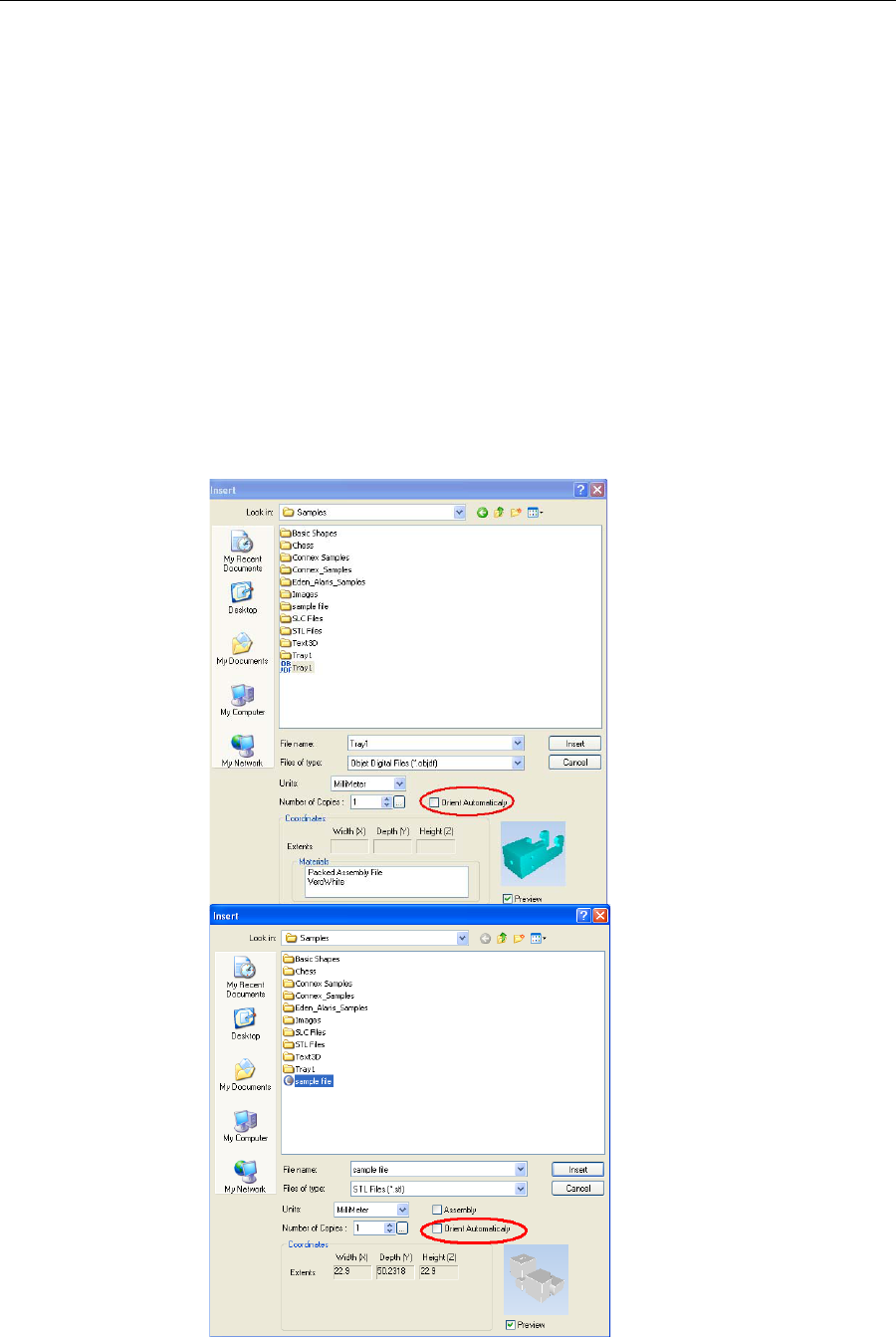
Using Objet Studio
5–22
DOC-07000 Rev. A
Positioning Objects on the Build Tray
Toproducemodelsefficientlyandwiththerequiredfinish,itisimportant
tocarefullypositionobjectsonthebuildtray.ObjetStudiosupportsthe
automaticpositioningofobjects.However,youshouldchecktomakesure
thattheobjectsareorientatedlogicallyforyourneeds,accordingtothe
considerationsexplainedin“ModelOrientation”onpage 5‐32.
Twothingsthataffectthepositioningofobjectsonthebuildtrayare
orientationandplacement.YoucanletObjetStudiodeterminetheoptimum
orientationandposition,oryoucancontrolthem.
Automatic
Orientation Bydefault,ObjetStudioautomaticallyorientsobjects,whenplacedonthe
buildtray,fortheshortestprintingtime.(Youcanlaterchangethe
orientationmanually.)However,youcancancelautomaticorientation
whenplacinganobjectonthebuildtray.
To place an object on the build tray without automatic orientation:
¾IntheInsertdialogbox,makesureOrientAutomaticallyisnotselected.

DOC-07000 Rev. A 5–23
Objet500 - Connex 3 User Guide
You can change the default setting, so that automatic orientation is not
applied unless you select the Orient Automatically check box each time you
place an object on the build tray. To do this, see “Default Settings” on
page 70.
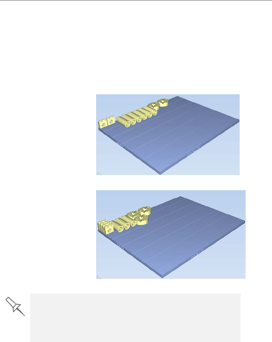
Using Objet Studio
5–24
DOC-07000 Rev. A
Automatic
Placement Afterplacingseveralobjectsonthebuildtray,youcanletObjetStudio
arrangethemonthetrayforprinting.Thisensuresthattheobjectsare
positionedproperly,andthattheywillbeprintedintheshortesttimeand
withaminimumofmaterial.
To automatically arrange objects on the build tray:
¾OntheTraySettingsribbon,click.
or—
FromtheToolsmenu,select Automatic Placement.
Theeffectsofautomaticpositioningareshowninthefiguresbelow.
Figure 5-20: Tray before
objects are properly arranged
Figure 5-21: Tray
arrangement when applying automatic placement
•For best results arrange the tray with Automatic Placement, on the Tray
Settings ribbon, even if you inserted the objects with the Orient
Automatically option.
•The physical characteristics of each type of model material you use can
affect the positioning of objects on the build tray. Therefore, select the
material before running Automatic Placement.

DOC-07000 Rev. A 5–25
Objet500 - Connex 3 User Guide
Model Orientation
Theorientationofmodelsonthebuildtrayaffectshowquicklyand
efficientlytheywillbeproducedbythe3‐Dprinter,whereandhowmuch
supportmaterialisused,andwhetherornotmodelpartswillhaveaglossy
finish.Therefore,youshouldconsideravarietyoffactorswhendeciding
howtoplacemodelsonthetray,usingthefollowingpositioningrules.
X-Y-Z Rule
Thisruleconsidersamodelʹsouterdimensions.
¾SincetheprintheadsmovebackandforthalongtheX‐axis,theprinting
timealongthisaxisisrelativelyshort,comparedtoprintingtimealong
theY‐axisandZ‐axis.Fromthispointofview,itisadvisabletoplacethe
objectʹslargestdimensionalongtheX‐axis.
¾Anysurfacesthatcomeintocontactwithsupportmaterialsbecome
matte.
¾Sincemodelsarebuiltup,ontheZ‐axis,in30‐micronlayers,itisvery
time‐consumingtoprintatallobject.Fromthispointofview,itis
advisabletoplacetheobjectʹssmallestdimensionalongtheZ‐axis.
¾Sincetheprintheadsmeasureabout2inches(5centimeters)ontheY‐
axis,modelsmeasuringlessthanthis(ontheY‐axis)areprintedinone
pass.Fromthispointofview,itisadvisabletoplacetheobjectʹs
intermediatedimensionalongtheY‐axis.
Tall-Left Rule
Thisruleconsidersmodelswhere,afterbeingorientatedonthebuildtray
accordingtootherconsiderations,onesideistallerthantheother.
¾SincetheprintheadsmovealongtheX‐axisfromlefttoright,taller
sectionsontherightrequiretheprintheadstoscanunnecessarilyfrom
theleftuntilreachingthem.If,ontheotherhand,thetallersectionsare
positionedontheleftofthetray,theprintheadsonlyhavetoscanthe
modeluntilprintingthesesections—oncethelowerpartshavebeen
completed.Therefore,youshouldpositionthetallersideofthemodel,
whenpossible,ontheleft.
Recess-Up Rule
Thisruleconsidersmodelscontainingsurfacerecesses.
¾Recessesinthesurface(likehollows,drillholes,etc.)should,when
possible,bepositionedface‐up.
Fine-Surface Rule
Thisruleconsidersmodelsthathaveonesideonwhichtherearefine
details(likethekeypadsideofatelephone).
¾Thesideofthemodelcontainingfinedetailsshould,whenpossible,be
positionedface‐up.Thisresultsinasmoothfinish.
Avoid Support-Material Rule
Thisruleconsidersmodelsthathavelargeholesorhollows,openonat
leastoneside(likeapipeoracontainer).
¾Itmaybeadvantageoustoprintamodelstandingup,sosupport
materialdoesnotfillthehollow,eventhoughprintingthemodellying
downwouldbemuchfaster.
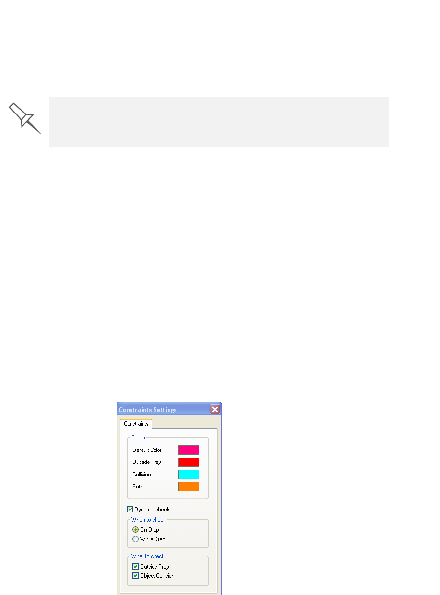
Using Objet Studio
5–26
DOC-07000 Rev. A
Manipulating Objects on the Build Tray
Positioning
Objects on the
Z-Axis
Whenyouusetheautomaticpositioningoptiontoarrangeobjectsonthe
buildtray,theobjectsarepositioneddirectlyonthetray.Ifyoudonot
insertobjectswithautomaticpositioning,theyoftenappeareitheraboveor
belowthetray.
To position objects directly on the tray:
1. Selecttheobject.
2. FromtheObjectmenu,selectLay On.
To ensure that objects are always positioned directly on the tray:
1. FromtheToolsmenu,selectOptions,anddisplaytheSettingstab.
2. IntheAutomaticLayOn(Gravity)section,selectAlways.
Other Z-axis options (in the Automatic Lay On section):
•When under the tray—Thedisplayofobjectsthatarebelowthebuild
trayisautomaticallychangedsothattheobjectisattraylevel.
•Never—Thedisplayofobjectsthatareaboveorbelowthebuildtrayis
notchanged.
Valid Object
Placement Youcanensurethatmodelsdonotoverlapwhenyoupositionthemonthe
buildtray,andthattheydonotextendbeyondthetray.
To ensure valid object placement:
1. FromtheToolsmenu,selectConstraints Settings.
In practice, the Objet system prints all models on the build tray on a one-
millimeter bed of support material. The importance of positioning objects
directly on the build tray with Objet Studio is to correctly display the objects
on the screen.

DOC-07000 Rev. A 5–27
Objet500 - Connex 3 User Guide
2. SelectDynamic checktoidentify:
•invalidobjectplacementwhileplacingobjects—OnDropselected.
•invalidobjectplacementaftermovingobjects—WhileDragselected.
•objectsplacedbeyondthetray’sboundaries—OutsideTrayselected.
•objectsthatoverlap—ObjectCollisionselected.
Note: Remember that Objet Studio calculates the space occupied by an
object including the “bounding box” surrounding it (see figure 5-40
on page 44).
Even if you do not use Dynamic Check when placing objects on the build
tray, Objet Studio automatically checks if there is a problem with the
positioning of objects on the tray before sending it to the printer. You can
also manually check for problems after positioning objects.
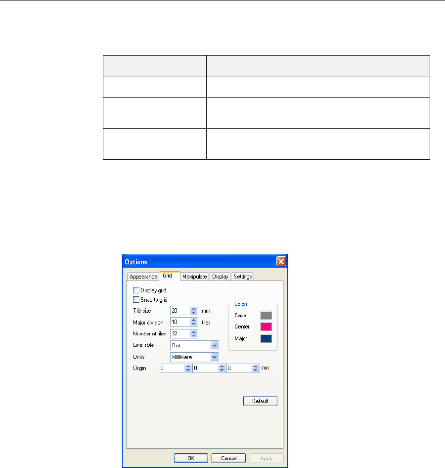
Using Objet Studio
5–28
DOC-07000 Rev. A
Using a Grid to
Position
Objects
Displayingagridontheimageofthebuildtraycanbeusefulwhen
positioningobjects.Youcanmakeuseofthisfeaturebyselectingthe
followingmenuoptions.
Youcanreviewandconfiguregridsettings—andapplythem—fromthe
Optionsdialogbox.
To view and change grid settings:
1. FromtheToolsmenu,selectOptions,anddisplaytheGridtab.
Thecurrentgridsettingsaredisplayed.
Figure 5-22: Options dialog box, Grid tab
2. Asrequired,changethesettings,andselectorclearthecheckboxes.
3. ClickApplyorOK.
Menu Option Result
Tools>Grid Displaysagridonthebuildtray.
Tools>Snaptogrid Whenmovingtheobject,italignswiththenearest
gridline.
Tools>Options>
Grid Enablesyoutochangethegridorigin
(X‐andY‐axismeetingpoint)andappearance.
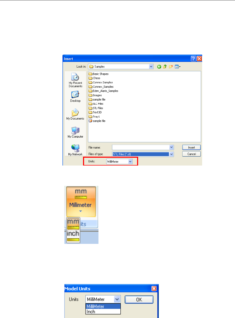
DOC-07000 Rev. A 5–29
Objet500 - Connex 3 User Guide
Measurement
Units
3‐Dfilescontainanobjectʹsproportions,butnotitsunitsofmeasure.
Therefore,makesuretocorrectlyselecteithermillimetersorincheswhen
insertinganobject.Otherwise,thesizeoftheobjectonthebuildtraywillbe
eithermuchtoolargeormuchtoosmall.
Tosetthemeasurementunitswheninsertinganobject:
¾IntheInsertdialogbox,Unitsfield,selectMillimeterorInch:
TochangeunitsofmeasurementontheModelSettingsribbon:
1. OpentheUnitsflyouttoolbar.
Figure 5-23: Units flyout toolbar
2. Selectthemeasurementunitsdesired.
To change units of measurement with the Standard Toolbar:
1. FromtheObjectmenu,selectChange Units.
Figure 5-24: Model Units dialog box
2. IntheModelUnitsdialogbox,changethesettingandclickOK.
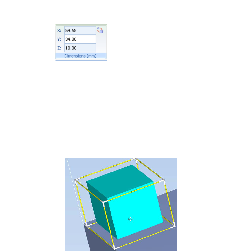
Using Objet Studio
5–30
DOC-07000 Rev. A
Setting Model
Dimensions Youcanchangetheobject’sdimensionsbychangingthecoordinatesinthe
DimensionsgroupontheModelSettingsribbon.
Figure 5-25: Dimensions on the Model Settings ribbon
Note: You can change the height of the objects on the build tray only if this
is allowed by the Objet Studio settings.
Repositioning
Objects Youcanmanuallymoveandrotateanobjectonthebuildtraywiththe
arrowkeys,orbydraggingitwiththemouse.
To manually manipulate an object:
1. Selectanobjectbyclickingitonthebuildtray,orinthemodeltree
pane.
2. ClickontheModelToolbar,orontheModelSettingsribbon.
Aframeappearsaroundtheobject,andthecursorchangestoindicate
thattheobjectcanbemoved.
Figure 5-26: Manually moving an object
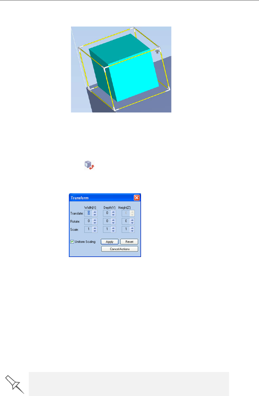
DOC-07000 Rev. A 5–31
Objet500 - Connex 3 User Guide
3. Ifyouclickonacorneroftheframe,thecursorchangestoindicatethat
theobjectcanberotated.
Figure 5-27: Manually rotating an object
4. Manipulatetheobjectwiththearrowkeysorwiththemouse.
Using the Transform
Dialog Box
Youcanmakeprecisechangestoanobjectbychangingthepropertiesinthe
Transformdialogbox.
To access the Transform dialog box (when an object is selected):
•ClickontheModelToolbarorontheModelSettingsribbon.
•Fromtheright‐clickcontextmenu,selectTransform.
•FromtheObjectmenu,selectTransform.
Figure 5-28: Transform dialog box
To change an object with the Transform dialog box:
¾Changeanyofthevalues,thenclickApplytoseehowtheobject
changesonthebuildtray.
Note: The changed values remain in the dialog box after clicking Apply.
Therefore, you can make small changes to values in the dialog box to see
how the object changes on screen each time you click Apply.
To reset all of the values in the dialog box:
¾ClickReset.
Note: The objet does not change. Any changes previously applied remain.
To undo all changes made with the Transform dialog box:
¾ClickCancel Actions.
After closing the Transform dialog box, clicking Undo (on the Model Settings
ribbon or from the Edit menu) cancels all changes made with the dialog box.
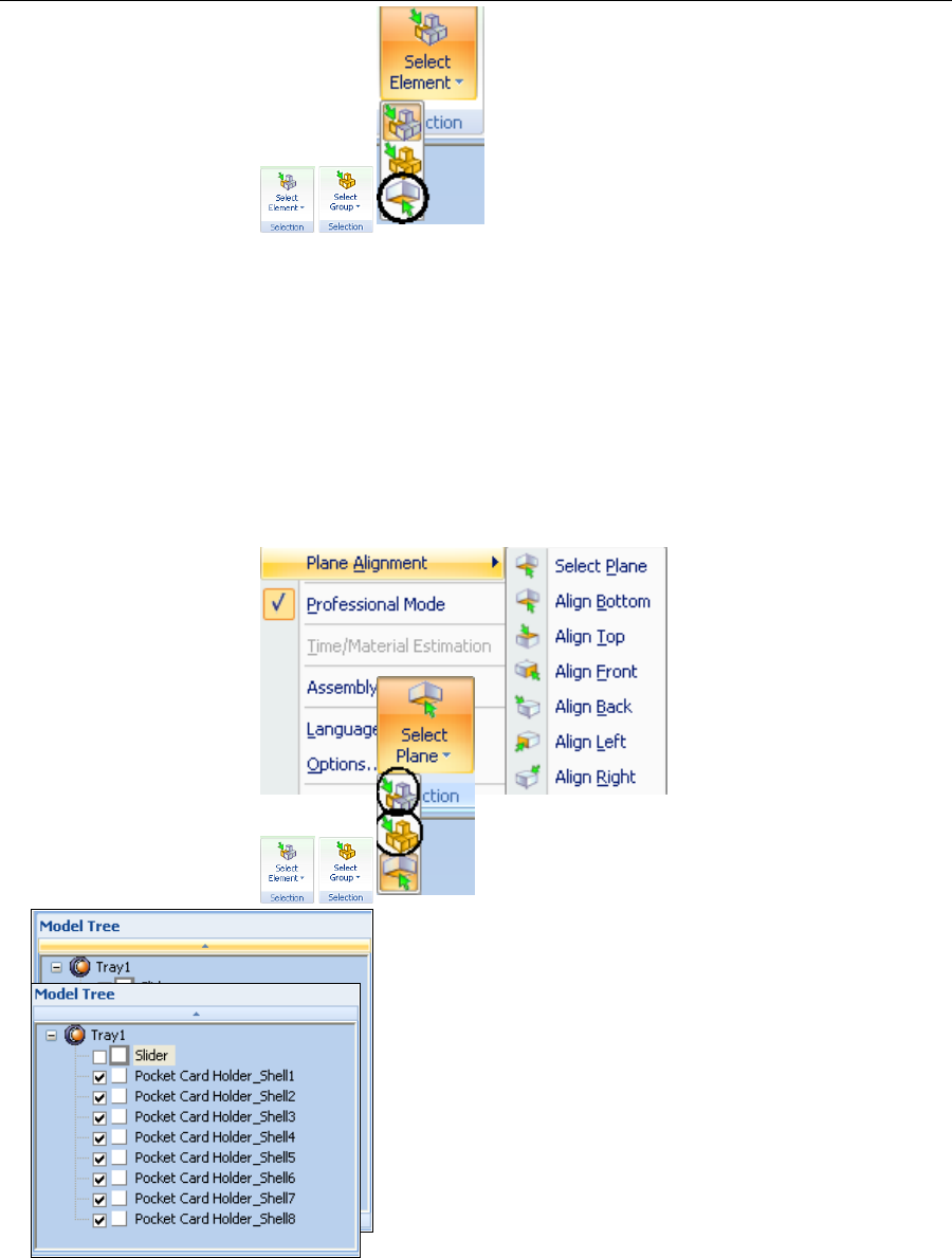
Using Objet Studio
5–32
DOC-07000 Rev. A
Changing an
Object’s
Orientation
Thereareseveralmethodsforchangingtheorientationofobjectsonthe
buildtray.
To rotate an object:
¾SelecttheobjectandusetheObjectmenuoptions.
To re-align an object’s plane:
or—
FromtheToolsmenu,selectPlane Alignment > Select Plane.
5. Clickonpartofanobjectonthebuildtray.
Theselectedplaneisdisplayed.
Figure 5-29: Aligning by plane
6. OntheAlignmenttoolbar,clickanappropriateicontochangethe
alignment.
or—
FromtheToolsmenu,selectPlane Alignment,andselectanalignment
option.
Figure 5-30: Tools menu, Plane Alignment options
To cancel plane selection after re-aligning objects on the build tray:
or—
FromtheToolsmenu,selectPlane Alignment > Select Plane.
To flip an object 180 degrees on any axis:
1. Selecttheobject.
2. FromtheObjectmenu,selectFlip > Flip X / Flip Y / Flip Z.
To make precise changes to the object’s orientation on any axis:
1. Selecttheobject.
2. DisplaytheTransformdialogbox.
3. ChangetheRotateparametersforeachaxis.
Freezing Model
Orientation
Ifyoumanipulateanobjectonthebuildtray,youcanfreezeitsorientation
sothatitdoesnotchangewhenyoupositionitautomatically().
To freeze an object:
1. Selectanobjectonthebuildtray.
2. OntheModelSettingsribbon,intheManipulategroup,orontheModel
Toolbar,click.

DOC-07000 Rev. A 5–33
Objet500 - Connex 3 User Guide
To unfreeze an object:
¾Selecttheobjectandclick(tode‐selectit).
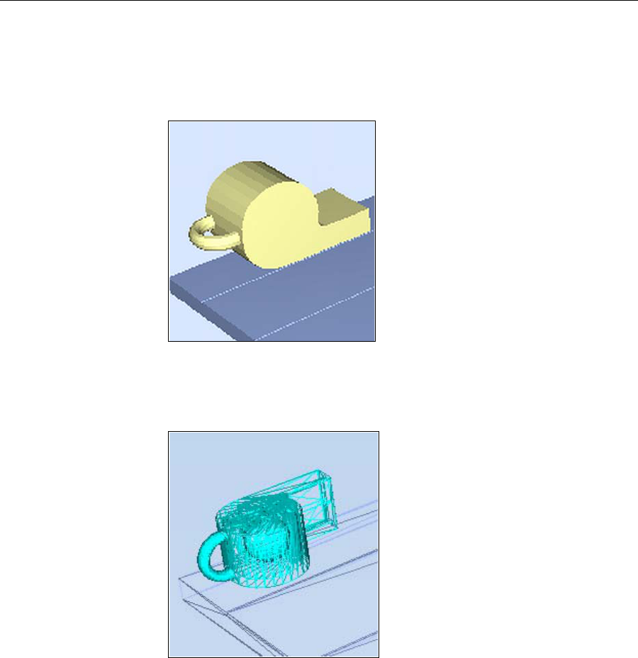
Using Objet Studio
5–34
DOC-07000 Rev. A
Display Options
Viewing
Objects FromtheViewmenu,youcanchangethewayobjectsaredisplayed.The
defaultmethodfordisplayingmodelsonthebuildtrayisassolid
(“shaded”)objects.
TheotherdisplayoptionsareWireFrameandPoints.
To display the build tray in WireFrame view:
¾FromtheViewmenu,selectWireFrame.
To revert to the shaded view:
¾FromtheViewmenu,select Shaded.
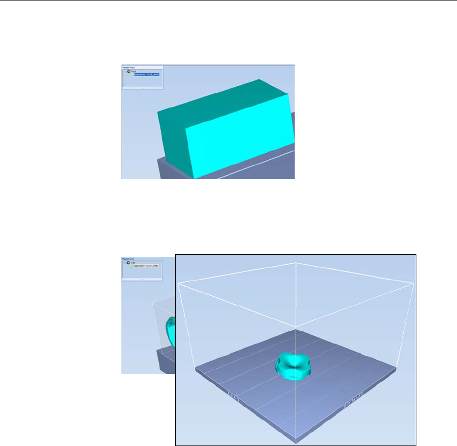
DOC-07000 Rev. A 5–35
Objet500 - Connex 3 User Guide
To display objects as boxes, showing their maximum dimensions
instead of their shape:
¾FromtheViewmenu,select Display Bounding Box.
Figure 5-31: Model displayed with bounding box
To display the area around objects needed for support material (to
produce a matte finish):
¾FromtheViewmenu,select Display Thickening Box.
Figure 5-32: Model displayed with thickening box
To display the maximum build height:
¾FromtheViewmenu,selectDisplay Tray 3D Box.
Figure 5-33: Tray 3-D
Box
To display objects without the build tray:
¾FromtheViewmenu,clear(de‐select)theDisplayTrayoption.
Screen Layout ObjetStudioautomaticallyadjuststhedefaultscreenlayouttodisplaythe
optimumviewsofthebuildtrayandthemodeltree.Youcanviewmodels
fromdifferentperspectivesbychangingthescreenlayout.
To change the screen layout:
¾OntheViewflyouttoolbar,selectSingle View,or4 Views.
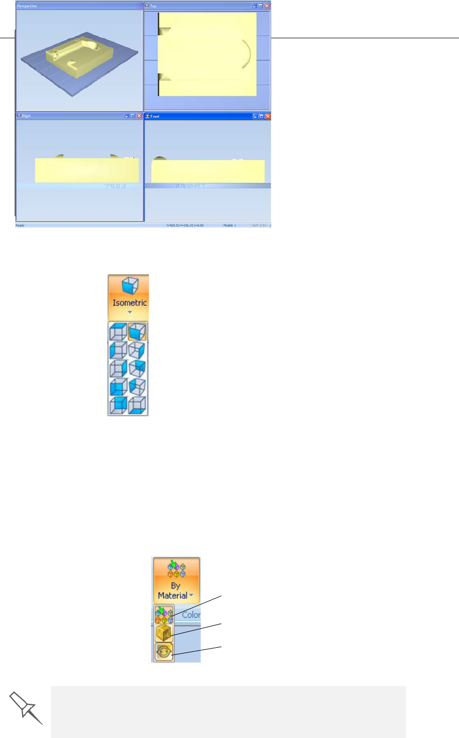
Using Objet Studio
5–36
DOC-07000 Rev. A
Figure 5-34: Screen layout icons
Single View isthedefaultscreenlayout.
4 Viewsdisplaysperspective,top,frontandrightviews.
Tray
Perspective
Thedefaultperspectiveofthebuildtrayis“isometric.”Youcanchangethe
perspectiveoftheactivewindowwithoneoftenoptions.
To change the perspective of the build tray in the active window:
1. OntheTraySettingsribbon,openthePerspectiveflyouttoolbar.
Figure 5-35: Perspective flyout toolbar
2. Clicktheiconthatrepresentsthedesiredperspective.
Tray Positioning Toviewthetrayandmodelsfromdifferentdirections,youcanmovethe
trayaroundthescreenandchangeitsdisplayangle.
To move the tray in the Objet Studio screen:
¾Pressthemousewheelwhilemovingthemouse.
To manually rotate the tray:
¾PressAltandpressthemousewheelwhilemovingthemouse.
Setting Object
Colors Thecolorofobjectsonthebuildtraycanindicatehowtheyareprinted.
ObjetStudioenablesyoutochoosethecolordisplaysothatyoucaneasily
seethematerial,surfaceofobjects.
To choose how colors are applied on the display:
¾OntheModelSettingsribbon,intheColorsgroup,selectoneofthe
optionsfromtheflyouttoolbar.
Figure 5-36:
Colors display options
Color Indicates Model material
Color indicates Model surface
Color indicates if coating is used
Before sending a build tray to the printer, or when you perform tray
validation, Objet Studio checks if there is a problem with the stl files or the
positioning of objects on the tray. If so, the affected objects are displayed
with special colors (see “Tray Validation” on page 5-51).
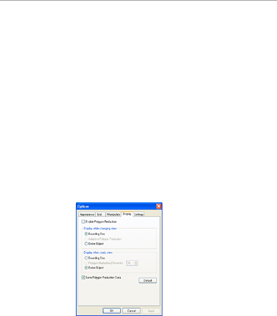
DOC-07000 Rev. A 5–37
Objet500 - Connex 3 User Guide
Loading Large
Files Verylargestlfilescanbeslowtoloadandmaybedifficulttomanipulate
easilyonthebuildtray.Ifthisisthecase,youcandisplayjustanimageof
theobjectonthebuildtraywithoutloadingtheentirefile.Thestlfileitself
isnotchanged,andthecompletefileissenttotheprinter.
To display an image of stl files when you place objects on the build tray:
1. FromtheToolsmenu,selectOptions,anddisplaytheSettingstab.
Figure 5-37: Options dialog box, Settings tab
2. IntheLargeFilessection,selectLoad Partial (reduced).
Large File
Manipulation Ifyouneedtoworkwithadetailedmodelthatiscomposedofalarge
numberofpolygons,youcanspeedupitsdisplayandmanipulationin
ObjetStudiobyreducingthenumberofpolygonsonthescreen.Although
thismayreducetheresolutiononthescreen,ithasnoaffectontheprinted
models.
Figure 5-38: Object displayed without polygon reduction
Figure 5-39: Object displayed with only five percent of its polygons showing
To use polygon reduction:
1. FromtheToolsmenu,selectOptions.
or—
IntheObjetStudioCommandsMenu,clickOptions.
2. IntheOptionsdialogbox,displaytheDisplaytab.
3. SelectEnable Polygon Reduction.
4. SelectPolygon Reduction (Percent).
5. Enterthepercentageoftotalpolygonstodisplay.
WhenyouclickApply,thedisplaychanges.
Note: The setting affects the static display (when the object is not being
moved).

Using Objet Studio
5–38
DOC-07000 Rev. A
6. Setdisplayoptionswhentheobjectisbeingmoved(Displaywhile
changingview):
•BoundingBox—Aboxrepresentingtheobject’smaximum
dimensionsisdisplayed.
•AdaptivePolygonReduction—Varyingdegreesofpolygonreduction
areapplied,asnecessary.
•EntireObject—Nopolygonreductionisapplied.
7. Tosavethesesettings,sothattheywillbeappliedeverytimeyouplace
thisobjectonthebuildtray,clickSave Polygon Reduction Data.
8. ClickApplytoseetheresultsofthesettingswithoutclosingthedialog
box.
Object display
options Thedisplayformataffectshowquicklyobjectsdisplay.Forexample,ifyou
selectBounding Box,objectsdisplayfasterthantheydowhenyouselect
Entire Object.Youcanchoosedisplayformatsforobjectswhentheyare
stationary(staticview)andforwhenyouaredraggingthem(changingview).
To select the object display preference while changing view, and in static
view:
1. Selecttodisplayobjects:
•WithaBoundingBox(seefigure 5‐40onpage 44)
•WithAdaptivePolygonReduction(changingviewonly)
•WithPolygonReduction(staticviewonly)
•EntireObject
2. ClickOKwhendone.
Zoom Options Whilemanipulatingobjects,youoftenneedtoviewthematdifferentzoom
levels.
To change the zoom level:
¾Ontheribbon,opentheZoomflyouttoolbarandselectanoption:
Figure 5-40: Zoom flyout toolbar
ZoomObjectfocusesontheselectedobject.
ZoomTraydisplaysthewholetray.
ZoombyRectangleallowsyoutodisplayasectionofthetrayby
selectingitwiththemouse.
Youcanalsozoominandzoomoutwiththemousewheel.
Selecting the Entire Object options cancels polygon reduction.
You can configure Objet Studio to automatically zoom in on the objects
placed on the build tray.
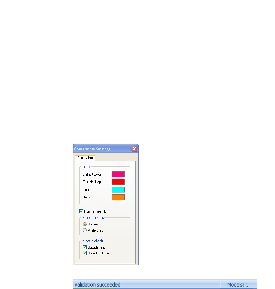
DOC-07000 Rev. A 5–39
Objet500 - Connex 3 User Guide
Handling Completed Trays
Afteryouhaveproperlyplacedallobjectsonthebuildtray,yousavethe
trayasanobjtffile,whichissenttothe3‐Dprinterforproduction.But
beforesavingthetray,youcancheckthattherewouldbenoproblem
producingit.Youcanalsocalculatehowmuchmaterialwouldbe
consumedduringproductionandhowmuchtimethiswouldtake.
Tray Validation Beforesendingajobtotheprinterforproduction,youshouldcheckthat
thetrayis“valid”andcanbeprinted.
To validate that the tray can be printed:
¾OntheTraySettingsribbon,intheBuildProcessgroup,click.
or—
FromtheToolsmenu,selectPlacement Validation.
Ifthetrayisnotvalid,thecoloroftheproblematicmodelsonthetray
changesaccordingtoapre‐setcode.
Thevalidationstatusappearsonthebaratthebottomofthescreen.
Figure 5-41: Validation details in status bar

Using Objet Studio
5–40
DOC-07000 Rev. A
Production
Estimates ObjetStudioenablesyoutocalculatethetimeandmaterialresources
neededforproducingtraysbeforesendingthemtotheprinter.Thetimeit
takesObjetStudiotomakethiscalculationdependsonthenumberof
objectsonthetrayandtheircomplexity.Calculatingtheproduction
estimateforafulltraycouldtakeupto15minutes,dependingonyour
computer’sspecifications.
To calculate the time and materials needed for producing the current
tray:
¾OntheTraySettingsribbon,intheBuildProcessgroup,click.
Whiletheestimateisbeingcalculated,aprogressbarisdisplayed—on
therightsideofthestatusbar(atthebottomofthescreen).
WhenObjetStudiofinishescalculatingtheproductionresources,the
resultsaredisplayed.
Figure 5-42: Production resource calculation
Youcane‐mailobjtffilesusingMicrosoft®OfficeOutlook®.
To e-mail a file:
1. FromtheToolsmenu,selectEmail Objet Digital File.
OutlookopenswiththefileattachedandSubjectdetailsaddedtothee‐
mailform.
2. Enterthee‐mailaddressandsendthefile.
Printing the
Tray File Whenatrayisreadytobeprinted,itisplacedintheJobsQueue.Whenthe
jobreachestheheadofthequeue,ObjetStudiopre‐processesthetrayfileto
createslices,andfeedsthemtothe3‐Dprinter.
To send the tray to the print queue:
1. OntheTraySettingsribbon,BuildProcessgroup,click.
Ifprintingthetrayrequiresmorethanonemodelmaterial(Digital
Materialmode),theJobSummarydialogboxopens.
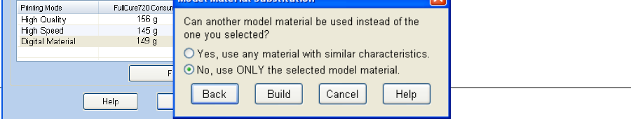
DOC-07000 Rev. A 5–41
Objet500 - Connex 3 User Guide
Ifthebuildtrayfilehasnot
beensaved,theSaveAsdialogboxopensforyoutosaveitnow.
ObjetStudiochecksifthereisaproblemwiththepositioningofobjects
onthetray.Ifso,theaffectedobjectsaredisplayedwithspecialcolors
(see“TrayValidation”onpage 51),andthefollowingwarningmessage
appears.
TocanceltheBuildcommandsoyoucancorrecttheproblem,click
No.Toprintthemodelsastheyarepositionedonthetray,clickYes.The
JobManagerscreenopens,soyoucanmonitortheprogressofyour
trays—before,during,andafterprinting.See“Monitoringand
ManagingPrintJobs”onpage 76.

Using Objet Studio
5–42
DOC-07000 Rev. A
Applying Additional Objet Studio Features
Dividing
Objects YoucanusetheSplitObjectfeaturetoproduceobjectslargerthanthetray
areabydividingthemodelintoseparateparts.Withthisfeature,you
produceonlyaspecificsectionofamodel.
To split an object:
1. Selecttheobject.
2. FromtheObjectmenu,selectSplit.
3. IntheSplitObjectdialogbox,enterthevaluestodeterminehowObjet
Studiowilldividetheobject.Youcandivideanobjectalonganyofits
axes,byenteringeitherexactmeasurementsorthenumberofparts.
Figure 5-43: Split Object dialog box
4. InSavetoFolder,enterthefoldername.
5. ClickOK.
Thecompositepartsaresavedasnewstlfileswith“Part1,”“Part2,”
etc.,addedtotheoriginalfilename.
Note: Before printing the newly created stl files, it is recommended that you
check them for defects in an STL-repair application, such as Magics,
by Materialise.
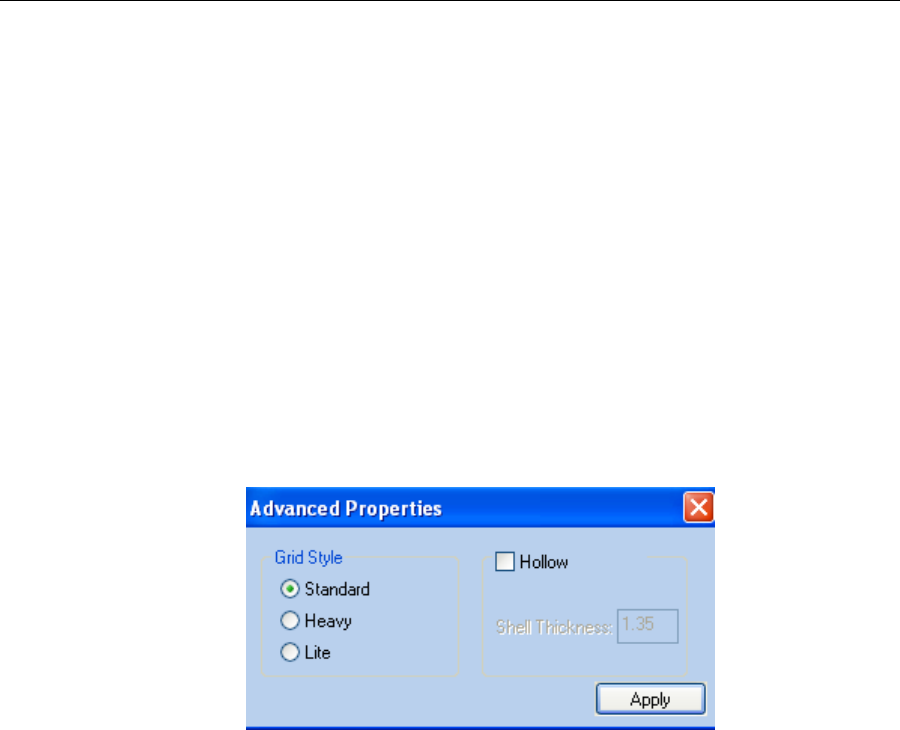
DOC-07000 Rev. A 5–43
Objet500 - Connex 3 User Guide
Choosing the
Support
Strength
Whenproducingmodels,supportmaterialfillssomehollowandempty
sections(see“ModelOrientation”onpage 5‐32).ObjetStudioallowsyouto
adjustthestrengthofthestructureformedwiththesupportmaterial.This
adjustmentisusefulwhenproducingeitherlarge/massivemodelsorsmall/
delicatemodels.Formostpurposes,thedefaultsettingprovidesadequate
supportstrength.
To change the strength of the support structure used when printing a
model:
1. Selectamodelonthetray.
2. OntheModelSettingsribbon,intheOptionsgroup,click.
or—
•OntheModelToolbar,click.
or—
•Fromtheright‐clickcontextmenu,selectAdvanced Properties.
TheAdvancedPropertiesdialogboxopens.
3. IntheGridStylesection,choosethesupportstrengthsuitableforthe
selectedmodel.Youcanselectadifferentsupportstrengthforeach
modelonthetray.
•Standard—formodelsneedingaveragesupport(mostmodels).
•Heavy—forlargemodelsneedingmuchsupport.
•Lite—fordelicatemodelsneedinglittlesupport.
4. ClickApply.
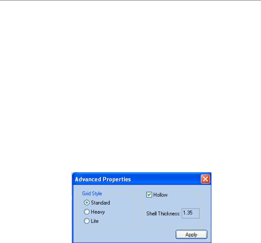
Using Objet Studio
5–44
DOC-07000 Rev. A
“Hollow”—
Filling Models
with Support
Material
Manyobjectsplacedonthetrayfromstlfilesare“solid.”Thismeansthat,
whenprinted,themodelwillbecompletelyfilledwithmodelmaterial.
Often,especiallywithlargeobjects,thisisunnecessary.Instead,themodel
canbefilledwithsupportmaterial,whichislesscostly.Itisalsoadvisable
tofillmodelswithsupportmaterialwhenpreparingthemforinvestment
casting,sincethismaterialburnsoffmorequicklyduringtheprocessof
makingthecast.
ObjetStudioenablesyoutoprintobjectsonthetraywithanoutershellof
modelmaterialandacenterfilledwithsupportmaterial.Thisfeatureof
ObjetStudioiscalled“Hollow.”Youcansetthethicknessoftheshell—
between0.015and3.825millimeters.
To use the Hollow feature:
1. Selectamodelonthetray.
or—
•OntheModelToolbar,click.
or—
•Fromtheright‐clickcontextmenu,selectAdvanced Properties.
TheAdvancedPropertiesdialogboxopens.
2. SelectHollow.
3. Settheshellthickness,inmillimeters.
4. ClickApply.
Note: There is no change in the display of objects in Objet Studio when
Hollow is selected.
To inspect, change or cancel the Hollow setting:
1. Selectamodelonthetray.
2. AccesstheAdvancedPropertiesdialogbox,asabove.
3. IfyouchangeorcanceltheHollowsetting,clickApply.
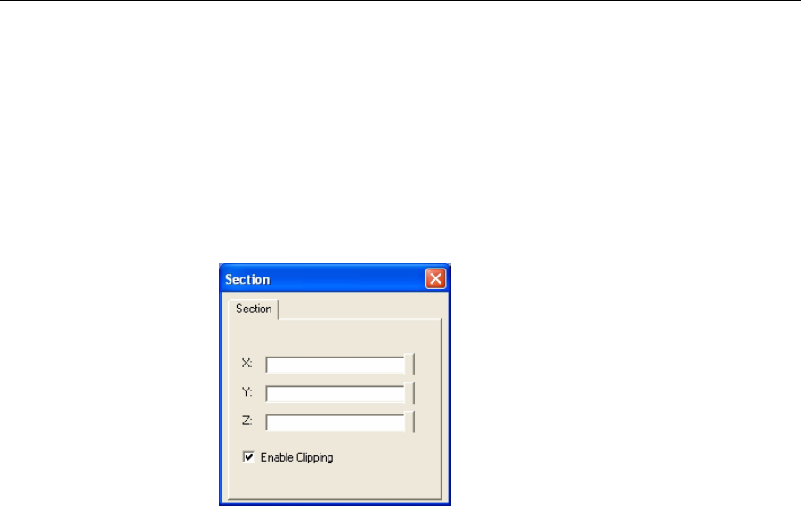
DOC-07000 Rev. A 5–45
Objet500 - Connex 3 User Guide
Displaying the
Cross Section
of Objects
TheSectionfeatureenablesyoutoviewtheinteriorofanobjectby“slicing”
itonanyaxis.Youcanthenmanipulatetheobjecttoinspecttheinterior
fromdifferentangles.Thismaybeimportantfordecidingonthetypeof
supportnecessarywhenproducingthemodel(see“ChoosingtheSupport
Strength”onpage 5‐59).Displayinganobject’scrosssectiononlyaffects
howthetrayisdisplayedonthescreen;itdoesnotchangetheobjectitself.
To display a cross section of the tray:
1. FromtheToolsmenu,selectSection.
TheSectiondialogboxopens.
Figure 5-44: Section dialog box
2. SelectEnable Clipping.
3. UsetheslidercontrolsfortheX‐,Y‐,andZ‐axestocutthetraysothat
youseethecrosssectionyouwant.
Figure 5-45: Whole view Figure 5-46: Cross-section view, after
using the Z-slider
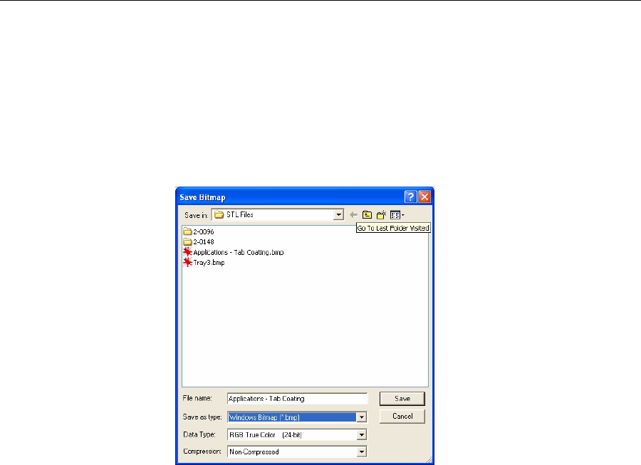
Using Objet Studio
5–46
DOC-07000 Rev. A
Saving the
Screen Display
as an
Image File
Youcansavetheimagedisplayedintheactiveviewingscreenasagraphic
file.
To save the screen display as an image:
1. PressCtrl+B.
or—
FromtheObjetStudioCommandsMenumenu,selectSave Bitmap.
TheSaveBitmapdialogboxopens.
2. Atthetopofthedialogbox,selecttheappropriatefolder.
3. Atthebottomofthedialogbox,enterafilename.
4. OpentheSaveastypepull‐downmenu,andselectthefileformat.
5. ClickSave.

DOC-07000 Rev. A 5–47
Objet500 - Connex 3 User Guide
Exporting and
Importing
Objet Build
Trays
WhenyousavebuildtraysinObjetStudio,theyaresavedasobjtffiles.
ThesefilescontaininstructionstoObjetStudioandtoObjetprintersfor
displayingandproducingthestlfilesusedonthetray.Toconveniently
saveallofthefilesthatcomprisethebuildtray,forstoringthejob,orfor
transferringittoanotherlocation,ObjetStudiocompressesthemintoone
objzffile.Tolaterusetheobjzffile,thefilemustfirstbeexpandedinObjet
Studioanditscomponentfilessaved.
Note: If you export an objzf file containing a stl file originally saved as read-
only, you cannot open (import) this objzf file to the folder where the
read-only stl file is saved.
To create an objzf file:
1. FromtheObjetStudioCommandsMenumenu,selectExport Packed
Job.
TheSaveAsdialogboxopens.
2. Selecttheappropriatefolderandchangethefilename(ifnecessary).
3. ClickSave.
To open an objzf file:
1. FromtheObjetStudioCommandsMenumenu,selectImport Packed
Job.
2. IntheOpendialogbox,displaytheappropriatefolderandselectthe
file.
3. IntheBrowseforFolderdialogbox,displaythefolderinwhichyou
wantObjetStudiotoexpandthecompressedfile,andclickOK.
Theobjtffileandassociatedstlfilesareexpandedandplacedinthe
selectedfolder,andthetrayisdisplayedinObjetStudio.
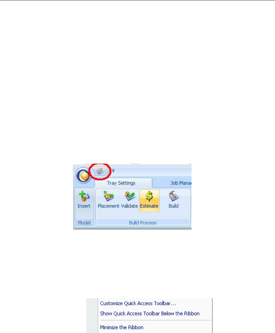
Using Objet Studio
5–48
DOC-07000 Rev. A
Customizing
Objet Studio
YoucancustomizeObjetStudiotosuityourparticularworkingneedsand
preferences.Featuresthatyoucancustomizeinclude:
•Creatingaquick‐accesstoolbarforfrequentlyusedcommands.
•ChangingthepositionoftheQuickAccesstoolbar.
•Minimizingtheribbon.
•ChangingtheObjetStudiocolortheme.
•Configuringdefaultsettingsforobjectsplacedonthebuildtray.
Creating a
Quick Access
Toolbar
AsyouworkwithObjetStudio,youmayusecertaincommandsfrequently.
Youcancreateaquick‐accesstoolbartomakeyourworkeasier.
To create a quick-access toolbar:
1. Abovetheribbontabs,click.
TheCustomizeQuickAccessToolbarmenuopens.
2. Selectacommandyouwanttoaddtothetoolbar.
Aniconfortheselectedcommandisaddedtothetoolbar.
Toaddanothercommand,repeattheaboveprocedure.
3. Tochoosefromawiderrangeofcommands:
•FromtheCustomizeQuickAccessToolbarmenu,selectMore
Commands.
or—
•Right‐clickontheObjetStudioCommandsicon,orelsewhereonthe
ribbon,andselectCustomize Quick Access Toobar.
Figure 5-47: Right-click ribbon menu
TheOptionsdialogboxopens.
Figure 5-48: Quick Access Toobar Options dialog box
4. Openthedrop‐downlistandselecteitherPopular Commandsor
Commands not on the Ribbon.
5. SelectacommandandclickAdd.
6. ClickOK.
Hiding the
Ribbon Tomakemoreroomfordisplayingthebuildtray,youcanhidetheObjet
Studioribbons.

DOC-07000 Rev. A 5–49
Objet500 - Connex 3 User Guide
To hide the ribbons:
1. Right‐clickanywhereontheribbonoronthemenubar,orintheObjet
StudioCommandsMenu.
2. SelectMinimize the Ribbon.
Theribbonsdisappear,butyoucantemporarilydisplaytheribbon
iconsbyclickingTray Settings orJob Manageronthemenubar.When
younextclickoutsideoftheribbon,itdisappearsagain.
To return the permanent ribbon display:
¾RepeatthestepsabovetocancelMinimizetheRibbon.
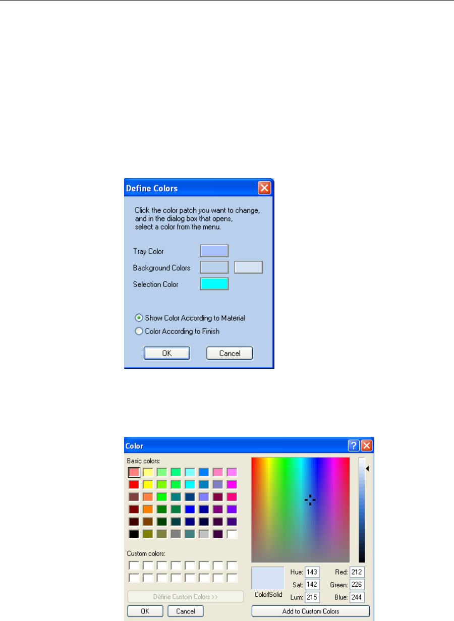
Using Objet Studio
5–50
DOC-07000 Rev. A
Display Colors YoucancustomizesomeofthecolorsusedfordisplayingObjetStudio
screensandfordisplayingobjectsonthebuildtray.
To change the colors used in Objet Studio screens:
1. FromtheToolsmenu,selectDefine Colors.
TheDefineColorsdialogboxappears.
2. IntheDefineColorsdialogbox,clickthecolorpatchyouwantto
change:
•TrayColor.
•BackgroundColors.
•SelectionColor.
3. IntheColordialogbox,selectoneoftheBasiccolors.
or—
ClickDefine Custom Colorstoexpandthedialogboxandallowyouto
defineacustomizedcolor.
4. ClickOK whendone.
Thepatchcolorinthedialogboxchangesaccordingtoyourselection.
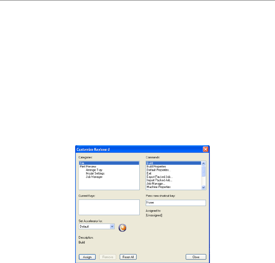
DOC-07000 Rev. A 5–51
Objet500 - Connex 3 User Guide
Changing Color
Themes ObjetStudiooffersachoiceoffourbackgroundcolorthemes—blue,black,
silverandaqua.
Figure 5-49: Background color themes
To change the color theme:
•FromtheStylemenu,selectoneoftheoptions.
Keyboard
Shortcuts Youcandefineshortcutkeysforfrequentlyusedcommands.
To define shortcut keys:
1. Abovetheribbontabs,click.
TheCustomizeQuickAccessToolbarmenuopens.
2. SelectMore Commands.
TheOptionsdialogboxopens(seefigure 5‐59onpage 64).
3. ClickCustomize.
TheCustomizeKeyboarddialogboxappears.
4. SelectcommandCategoriestodisplayallthecommandsinthat
category,forexample,alltheModelSettingscommands.
Currentshortcutkeysaredisplayed.
5. Entertheshortcutkeyinthe Pressnewshortcutkeyfield,andclick
Assign.
6. Ifyouwanttoredefineallshortcutkeys,clickReset All.
Setting User
Preferences YoucanchangeseveralObjetStudiosettingsthataffectobjectsplacedon
thebuildtray.
To change default settings:
¾FromtheObjetStudioCommandsMenu,selectUser Preferences.
•BuildingStyle—see“SurfaceFinish”onpage 25.
•GridStyle—see“UsingaGridtoPositionObjects”onpage 35.
•ApplicationSettings—see“ChoosingtheSupportStrength”onpage 59,
and“FreezingModelOrientation”onpage 42.
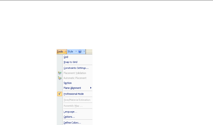
Using Objet Studio
5–52
DOC-07000 Rev. A
Professional Mode Features
SomeadvancedfeaturesofObjetStudioareonlyaccessibleinProfessional
Mode.
To see the current Objet Studio setting:
¾OpentheToolsmenu.
IfProfessionalModeischecked,advancedfeaturesaredisplayed.
To change the Professional Mode setting:
1. FromtheToolsmenu,selectProfessional Mode.
Thefollowingmessageisdisplayed,remindingyouthatthechange
willonlytakeeffectthenexttimeyouopenObjetStudio—eventhough
thecheckmarknexttotheProfessionalModeoptionappears
immediately.
Figure 5-50: Configuration-change message
2. Closeandre‐openObjetStudiotousetheProfessionalModefeatures.
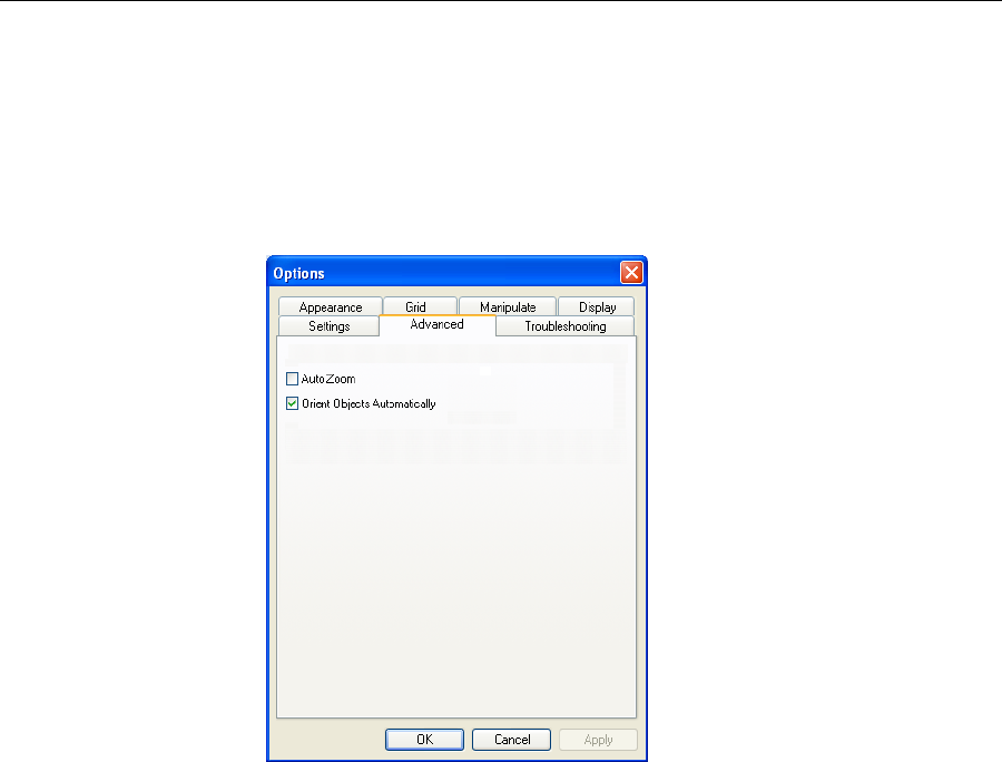
DOC-07000 Rev. A 5–53
Objet500 - Connex 3 User Guide
Default
Settings YoucancontrolthedefaultsettingsofseveralObjetStudiofeaturesfrom
theAdvancedtaboftheOptionsdialogbox.
To display the Options dialog box
¾FromtheToolsmenu,selectOptions.
or—
IntheObjetStudioCommandsMenu,clickOptions.
Bydefault,whenObjetStudioplacesobjectsonthebuildtray,itorients
themoptimally,fortheshortestprintingtime.Ifnecessary,youcanchoose
tocancelautomaticorientationeachtimeyouplaceanobjectonthebuild
tray(see“AutomaticOrientation”onpage 28).Inanycase,whenobjects
areonthebuildtray,youcanchangetheirorientationmanually,if
necessary—see“ModelOrientation”onpage 32.)
To change the default setting so that Automatic Orientation is disabled:
¾IntheAdvancedsectionoftheOptionsdialogbox,clearthecheckbox.
WhenAutoZoomisselectedintheAdvancedsectionoftheOptionsdialog
box,thedisplayzoomstodisplaytheobjectsplacedonthebuildtray.This
allowsyoutocarefullyinspectandmanipulatetheobjects.
Bydefault,thisfeatureisnotenabled.Inanycase,youcanchangethe
zoomlevel,asnecessary(see“ZoomOptions”onpage 50).
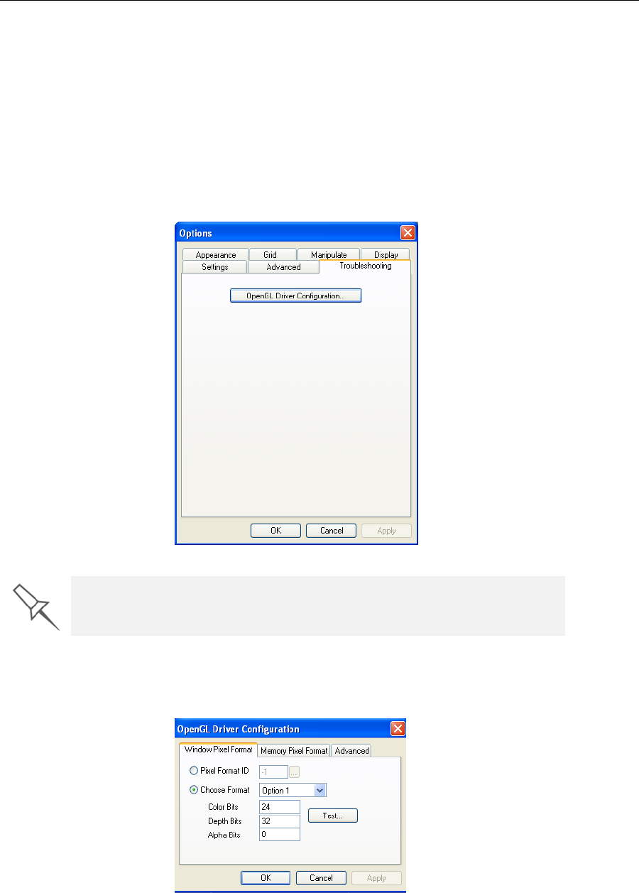
Using Objet Studio
5–54
DOC-07000 Rev. A
Open GL
Driver
Configuration
TheOpenGLdriverdisplays3‐Dgraphicsonyourscreen.Thereis
normallynoreasontoadjustitssettings.Ifyoususpectaproblemwiththe
wayObjetStudiodisplaysobjects,youcanusetheOpenGLDriver
Configurationtooltocheckandconfigurethedriversettings.
To access the OpenGL Driver Configuration dialog box:
1. FromtheToolsmenu,selectOptions.
or—
IntheObjetStudioCommandsMenu,clickOptions.
2. IntheOptionsdialogbox,displaytheTroubleshootingtab.
3. ClickOpenGL Driver Configuration.
ThedialogboxthatopensdisplaysdetailsofthepixelformatID(index)
forthewindowandthememory.
Figure 5-51: OpenGL Driver Configuration dialog box
Ifyouwanttodisplaythevaluesandchangethem,click.Alternately,
youcanselectChoose Formatandchangethevaluesinthisdialogbox.
The Troubleshooting tab is only accessible when Professional Mode is
active (see Professional Mode Features).
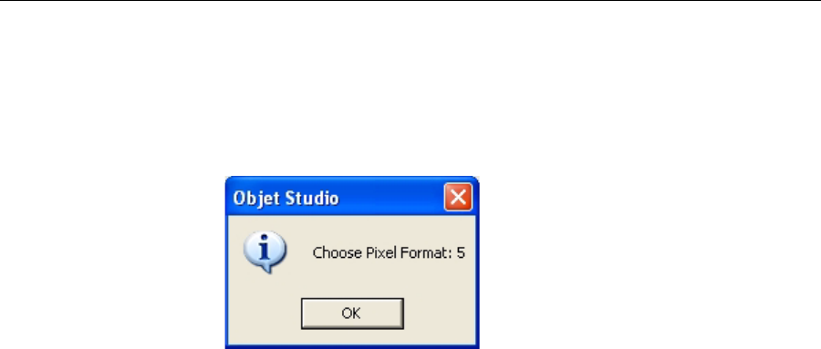
DOC-07000 Rev. A 5–55
Objet500 - Connex 3 User Guide
To perform a test of the driver configuration and enter the suggested
pixel format ID:
1. SelectChoose Format.
2. ClickTest.
ObjetStudioreturnstherecommendedpixelformatID.
Figure 5-52: Recommended pixel format ID
3. ClickOK.
4. IntheOpenGLDriverConfigurationdialogbox,selectPixel Format ID
andenterthisnumber.
5. ClickApply.
6. Displaytheotherpixelformattab,andrepeatthisprocedure.
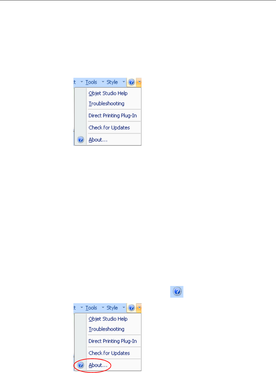
Using Objet Studio
5–56
DOC-07000 Rev. A
Getting Additional Objet Studio Assistance
ObjetStudioHelpprovideson‐screeninformation,asyouwork.
To view Objet Studio Help:
•PressF1.
or—
Onthestandardtoolbar,clickandthenclickObjet Studio Help.
Figure 5-53: Help options
Youcanalsoviewinformationonthefollowingsubjects:
•Troubleshootingopensalistoferrormessagesandtheir
explanations.
•DirectPrintingPlug‐inopensinformationonadditionalsoftware
programsthatextendthecapabilitiesofObjetStudio.
•CheckforUpdateschecksifyouareusingthelatestObjetStudio
version.
About Objet Studio
AboutObjetStudioprovidesdetailsofyourinstalledversion,material
modulesandyourObjetStudiolicenseinformation.
To view About Objet Studio:
•PressF1.
or—
Onthestandardtoolbar,clickandthenclickAbout....
Figure 5-54: About...
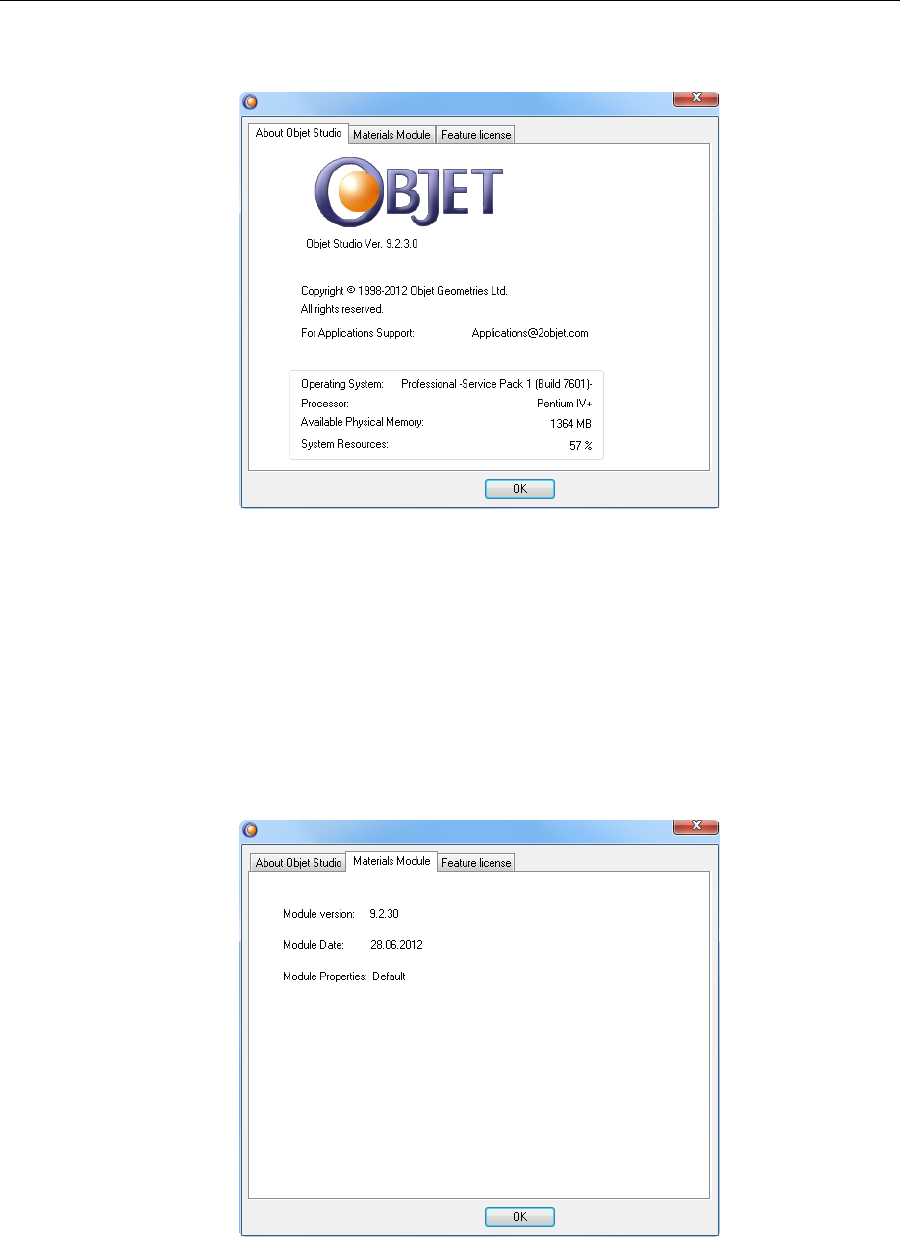
DOC-07000 Rev. A 5–57
Objet500 - Connex 3 User Guide
About Objet
Studio TheAboutObjetStudiotabshowsyourObjetStudioversionnumber,
Objet’ssupportemailaddressandbasicinformationaboutyourcomputer.
Figure 5-55: About Objet Studio
Materials
Module TheMaterialsModuletabshows:
1. Moduleversion—thelatestpatchinstalled.Iftherearenopatches
installed,themoduleversionisthesameastheObjetStudioversion
number.
2. Moduledate—thedateofthelatestpatchwascreated.Ifthereareno
patchesinstalled,themoduledateisthedateofthecurrentObjet
Studioversion.
3. Moduleproperties—adescriptionofthepatch.Iftherearenopatches
installed,themodulepropertiesvalueis“Default”.
Figure 5-56: Materials Module
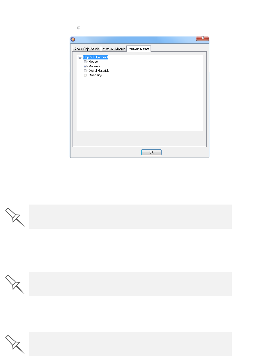
Using Objet Studio
5–58
DOC-07000 Rev. A
Feature
License TheFeatureLicensetabshowstheObjetStudiofeaturesforwhichyouare
licensed.
Clicktoexpandthelicensedetailsforeachfeature.
Figure 5-57: Feature License
Modes
ModesshowstheprintingmodesforwhichyourversionofObjetStudiois
licensed,suchasHighSpeed,HighQualityandDigitalMaterial.
Materials
Materialsshowsthenamesofallparentmaterialsforwhichyourversionof
ObjetStudioislicensed.Forexample,FullCure720,VeroBlackand
VeroGrey.
DigitalMaterials
DigitalMaterialsshowsthenamesofalldigitalmaterialsforwhichyour
versionofObjetStudioislicensed.
MixedTray
MixedTrayshowswhetheryourlicenseallowsforprintingamixedtray.A
mixedtrayisabuildtraycontainingobjects,eachofwhichisdesignedto
beprintedusingadifferentmodelmaterial.
Available modes may vary, depending on your printer model.
Available materials may vary, depending on your printer model.
Available digital materials may vary, depending on your printer model.

DOC-07000 Rev. A 5–59
Objet500 - Connex 3 User Guide
Monitoring and Managing Print Jobs
IntheJobManagerscreenofObjetStudio,youmonitorandmanagejobs
senttotheprinter.ThereareafewdifferencesbetweenObjetStudioon
clientworkstationsandonthecomputerconnecteddirectlytothe3‐D
printer—theserverworkstation.
•ObjetStudioinstalledonaclientcomputeronlydisplaysthequeueand
statusforjobssenttothe3‐Dprinterserverfromthatcomputer,andit
allowstheusertoeditonlythesejobs.
Note: If there are several Objet printers on the local network, client
computers can connect to any of them, but only one at a time.
•ObjetStudioinstalledonthecomputerdirectlyconnectedtoaspecific
3‐Dprinter(server),displaysthequeueandstatusforalljobssentto
that3‐Dprinterbytheserverandbyallclientcomputersonthe
network.Italsoallowseditingandmanipulationofalljobs,andenables
re‐sendingpreviously‐printedjobstotheprinter.
Job Manager
Screen TheJobManagerscreenontheclientandserverworkstationslooks
identical.Theonlydifferenceisthatoptionsonlyrelevanttotheserver
workstationaredisabledforclientinstallations.
Figure 5-58: Job Manager screen
TheJobManagerscreenisdividedintopanels:
•JobsQueue
•PrintTime
•History
•AvailableResources
•MaterialConsumption
•TrayPreview
•Waste
If Objet Studio is not connected to a printer (or printer server), you can
prepare tray files for any Objet printer. Later, these files can be used by
Objet Studio on the appropriate printer server.

Using Objet Studio
5–60
DOC-07000 Rev. A
Jobs Queue Ontheserver,theJobsQueueliststhelast15jobssentfromclient
computers.Onclientworkstations,theJobsQueuelistsjobssentfromthat
computertotheprinterserver.
Informationforeachofthequeuedjobsisdisplayed,includingthejob
status.
Inaddition,thefollowinginformationisdisplayed:
•Owner—thecomputerthatsentthejob.
•BuildTime—theestimatedbuildingtimeforthejob.
•ModelConsumption—theamountofmodelmaterialrequiredto
completethejob,andtheamountactuallyusedtillnow.
•SupportConsumption—theamountofsupportmaterialrequiredto
completethejob,andtheamountactuallyusedtillnow.
Print Time TheTimepanelshowsprintingtimesandthenumberofslicessenttothe
printer.
History TheHistorypanelshowsinformationforthelast50jobsandtheirfinal
status.YoucandragajobfromHistorytoJobsQueuetoprintthetrayagain.
Available
Resources TheAvailableResourcespanelcontainsgraphicindicatorsthatshowthe
amountofavailableprintingmaterialremaining.
Material
Consumption •Actual—theamountofmaterialusedtillnow
•Required—theamountofmaterialstillneededtofinishthejob
Tray Preview TheTrayPreviewpaneldisplaysthebuildtrayviewofthejobselectedinthe
JobQueueortheHistorylist.
Onaserver,youcanopenanenlargedpreviewwindowbyclickingonthe
TrayPreviewdisplay(see“ExtendedTrayPreview”onpage 87).
Waste IfyoumovethemouseovertheWastedisplay,theamountofwasteinthe
containerisdisplayed.
Status Meaning
Waiting Printingofthisjobhasnotstarted.
Building Printingofthisjobisinprogress.
Stopped Printingofthisjobwasinterrupted.Printingcanlaterbe
continued(Resume)orbegunagain(Restart).
Error Errorsoccurredduringtheprintingofthisjob,anditwas
placedintheJobsQueueagain.
Editing ThisjobisnowbeingeditedinObjetStudio.
Spooling Thejobfileisbeingspooledintheprinter.
Preprocessing The3‐Dprinterisreadyingitselfforprinting:thecover
locks,printheadswarmupandareputinstarting
position,UVlampturnedon,andthebuildtraylevelis
adjusted.
OnSchedule Thejobisscheduledtobeprintedataspecifiedtime.
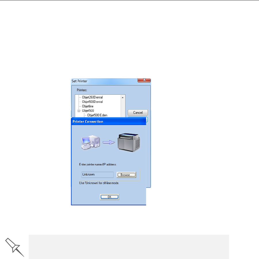
DOC-07000 Rev. A 5–61
Objet500 - Connex 3 User Guide
Setting the
Printer
Connection
WhenanObjet3‐Dprinterisinstalled,theservercomputerisconnectedto
thatprinter.Normally,thereshouldbenoreasontochangethisconnection.
Occasionally,however,youmayneedtoresettheconnection,toconnect
theservertoanotherprinter,ortouseObjetStudioinoff‐linemode
(withoutaprinterconnection).
To set (or change) the printer connection:
1. OntheJobManagerribbon,inthe3DPrintergroup,click.
2. IntheSetPrinterdialogbox,clickConnect.
3. EnterthecomputernameoritsIPaddress,orclickBrowsetofindand
selectit.
4. ClickOK.
Whentheconnectionisestablished,ObjetStudioisconfiguredto
prepareprintjobsforthatprinter.
Objet Studio is connected to the printer if you can see the material levels in
the Job Manager screen.
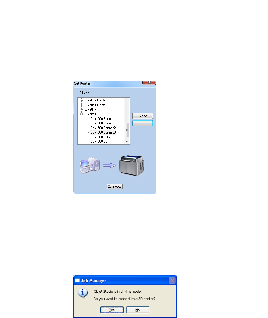
Using Objet Studio
5–62
DOC-07000 Rev. A
Off-line Mode YoucanuseObjetStudiotopreparetraysforprintinginoff‐linemode,on
aremotecomputerorwhentheprinterconnectionisnotavailable.Youalso
useoff‐linemodetopreparetraysforprintingwithotherprinters.Inthis
case,ifObjetStudioiscurrentlyconnectedtoaprinter,youmustchangeto
off‐linemodebyremovingthisconnection.
To disconnect Objet Studio from the printer:
1. OntheJobManagerribbon,inthe3DPrintergroup,click.
2. IntheSetPrinterdialogbox,clickConnect.
Figure 5-59: Disconnecting Objet Studio from a printer (A)
3. PrinterConnectiondialogbox,deletethecomputername/IPaddress.
Figure 5-60: Disconnecting Objet Studio from a printer (B)
4. ClickOK.
“Unknown”appearsintheprinter‐namefield.
5. ClickOK.
6. Inthepop‐upmessage,confirmthatyouwanttoworkinoff‐linemode
byclickingNo.
WhenObjetStudioisinoff‐linemode,youcanconfigureitforpreparing
printjobsfordifferentprinters.
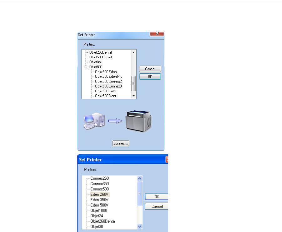
DOC-07000 Rev. A 5–63
Objet500 - Connex 3 User Guide
To change the Objet Studio off-line configuration:
1. IntheSetPrinterdialogbox,selectaprintertype.
2. ClickOK.
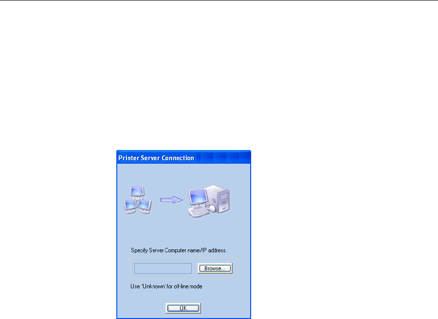
Using Objet Studio
5–64
DOC-07000 Rev. A
Setting the
Remote Printer
Connection
(Client Mode)
WhenyouopenObjetStudioforthefirsttimeinaclientinstallation,you
arepromptedtoconnecttoanObjetservercomputerthatsendsjobstoa3D
printer.Todothis,theservercomputermustbeoperatingandconnectedto
thelocalnetwork.
To set (or change) the connection to the server-computer:
1. OntheJobManagerribbon,inthe3DPrintergroup,click.
2. EnterthenameoftheservercomputeroritsIPaddress,orclick
Browsetofindandselectit.
3. ClickOK.
Figure 5-61: Printer Server Connection dialog box
Job Manager
Commands TheJobManagerribbonhasthreeicongroups:
•3DPrinter
•Queue
•Job
Figure 5-62: Job Manager ribbon commands
Iconsareenabledordisabledaccordingtotheirrelevancy.Forexample,
youcannotstopprintingajobthatisnotbeingprinted,sotheStop
commandisdisabled.
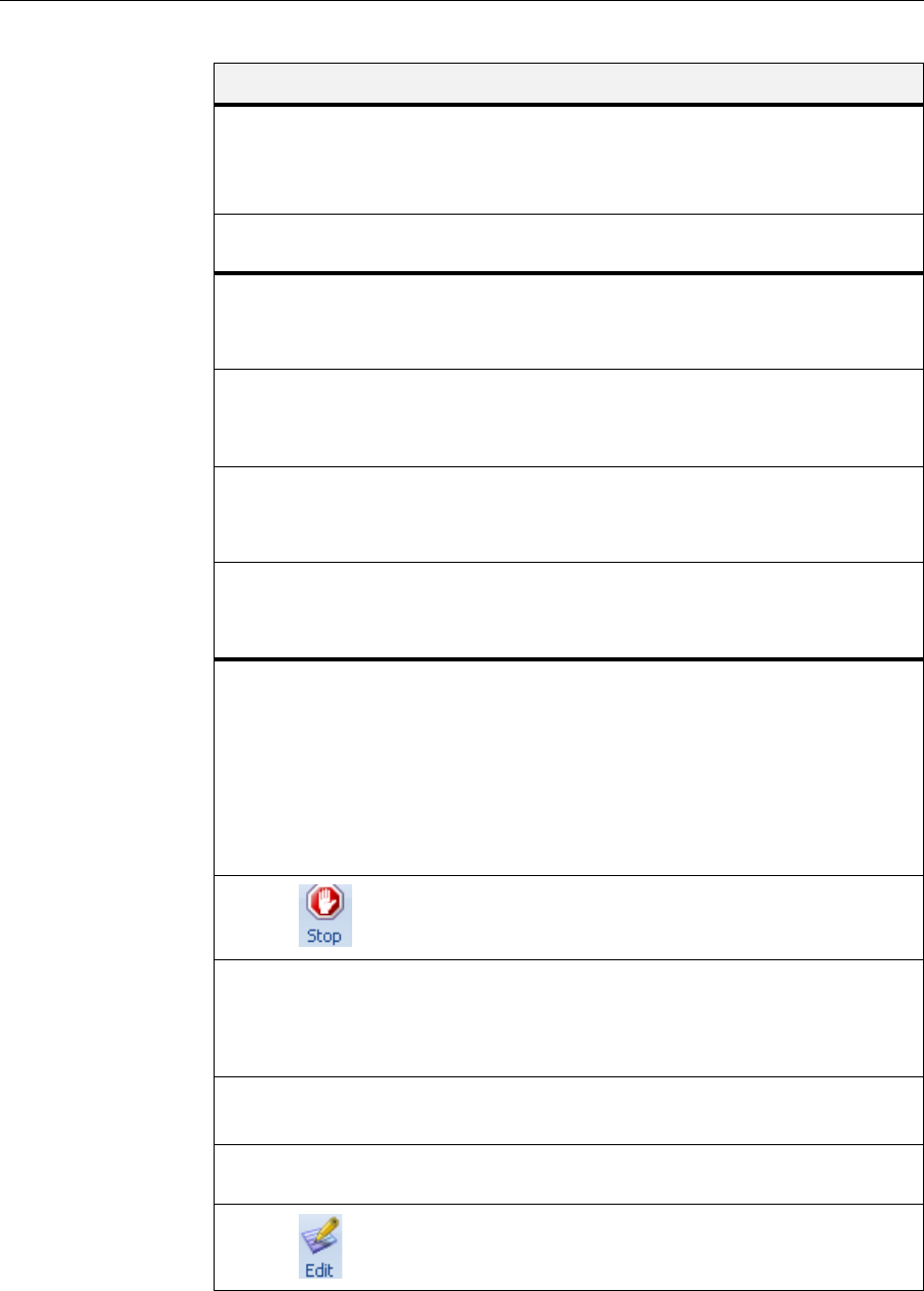
DOC-07000 Rev. A 5–65
Objet500 - Connex 3 User Guide
ThefollowingoperationsareavailableontheJobManagerribbon:
Inadditiontousingribboncommandicons,youcanusecommandson
context(pop‐up)toolbarsandfromtheJobmenuonthestandardtoolbar.
Figure 5-63: Icons on pop-up toolbar (server)
Group Icon Purpose
3D
Printer
Client:Setstheserverconnection.See“SettingtheRemote
PrinterConnection(ClientMode)”onpage 82.
Server:Setstheprinterconnection.See“SettingthePrinter
Connection”onpage 78.
Configuresoptionsforprinteralerts.See“ConfiguringUser
Alerts”onpage 85.
Queue Server:MovesajobtotheheadoftheJobsQueue.
Client:Disabled.
See“JobsQueue”onpage 77.
Server:MovesajobtoahigherpositionintheJobsQueue.
Client:Disabled.
See“JobsQueue”onpage 77.
Server:MovesajobtothebottomoftheJobsQueue.
Client:Disabled.
See“JobsQueue”onpage 77.
Server:MovesajobtoalowerpositionintheJobsQueue.
Client:Disabled.
See“JobsQueue”onpage 77.
Job Server:
•ForajobintheJobsQueue—Printsitagain(fromthe
beginning).
•ForajobintheHistorylist—MovesittotheJobsQueue
forprinting.
Client:Disabled.
See“RestartingJobs”onpage 88.
Server:Stopsajobinprogress.
Client:Disabled.
Server:Continuesprintingthecurrentjobfromthepoint
whereprintingstopped.
Client:Disabled.
See“ResumingJobs”onpage 88.
Removestheselectedjobfromthequeue.
RefreshestheimageoftheselectedjobintheTrayPreview
display.
OpenstheTraySettingsscreenanddisplaysthetray.For
deletedjobs,thisenablesyoutomakechangesbefore
printing.
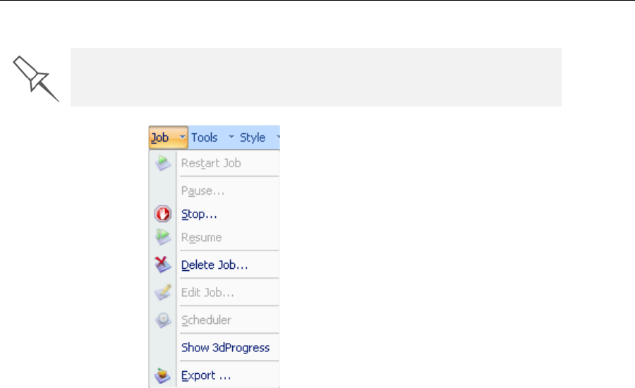
Using Objet Studio
5–66
DOC-07000 Rev. A
Figure 5-64: Icons on pop-up toolbar (client workstation)
Figure 5-65: Job menu options (server)
When you position the cursor over an item, a tooltip displays the name of
the command.
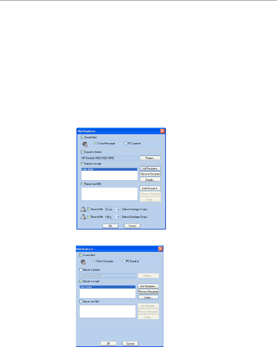
DOC-07000 Rev. A 5–67
Objet500 - Connex 3 User Guide
Configuring
User Alerts ObjetStudiocanalertyou(andothers)tothestatusofjobssenttotheserver
forprinting.Thisisespeciallyusefulduringlongprintingjobs,whenthe
operatorisawayfromtheprinter.Thefollowingeventscanbereported:
•Thelevelofmodelorsupportmaterialislow.
•Thejobwasinterrupted.
•Thejobwascompletedsuccessfully.
Tosende‐mailandSMSalerts,makesurethate‐mailsoftwaresupporting
MAPIisinstalledontheservercomputer.TosendSMSalerts,thecellular
phoneservicemustsupportthetransmissionofe‐mailmessagesbySMS.
Onlythesubjectlineofthee‐mailmessageistransmittedbySMS.
To configure Objet Studio to send notifications and alerts:
1. OntheJobManagerribbon,inthe3DPrintergroup,click.
Figure 5-66: Notifications dialog box (server)
Figure 5-67: Notifications dialog box (client workstation)
2. Setthedesiredreportingoptions.

Using Objet Studio
5–68
DOC-07000 Rev. A
3. ClickDetails.
Figure 5-68: Event selection for alerts
4. IntheReportsEventsdialogbox,selectthealerteventsandclickOK.
5. IntheNotificationsdialogbox,clickOK.
Printing the
Tray IfthereisajobintheJobsQueue,itissentautomaticallytotheObjet
printer—aslongasitison,thereisaconnectiontotheprinter,andthe
printerisonline.
Additional
Server
Features
ObjectStudioontheprinterserversincludesthefollowingadditional
features:
•ExtendedTrayPreview
•EditingJobs
•RestartingJobs
•ResumingJobs
•SchedulingJobs
•ExportingJobs(objzf)
•ModifyingtheJobManagerScreen
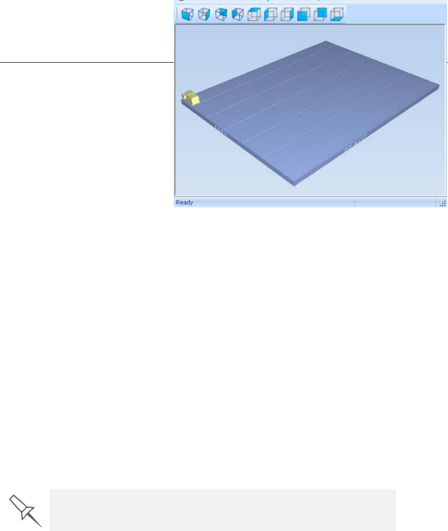
DOC-07000 Rev. A 5–69
Objet500 - Connex 3 User Guide
ExtendedTrayPreview
Inthiswindow,youcanviewthetrayfromdifferentanglesand
magnificationswithoutleavingtheJobManagerscreen.Inadditionto
displayingtheselectedjobintheTrayPreviewpane,youcanopenan
enlargedbuildtraywindow.
To display the build tray window:
1. SelectajobintheJobsQueueortheHistorylist.
2. ClicktheTrayPreviewpane.
Figure 5-69:
Job Preview
•Tochangethetraymagnification,turnthemousewheel.
•Toviewthetrayfromadifferentperspective,clicktherelevanticon.
•Toresizethewindow,dragitsedgeorcorners.
Ifthereareseveralobjectsonthebuildtray,youcanexcludeoneormore
frombeingprinted,withoutactuallydeletingtheobjectfromthetrayfile.
To prevent the printing of an object on the build tray:
1. Double‐clickontheobjectyoudon’twanttoprint.
2. DisplaytheBuildtab.
3. SelectExclude from Build.
Figure 5-70: Excluding a model from the build
4. ClickYestoconfirm.
Onservercomputers,youcanuseTrayPreviewtodynamicallydisplay
objectsastheyareprinted,layerbylayer.Thisenablesyoutovisually
monitorprintingprogressonthecomputerscreen.
To display printing progress in the Tray Preview pane:
¾FromtheJobmenu,selectShow 3dProgress.
EditingJobs
YoucanopenjobsintheJobsQueueforediting.
To edit a job:
1. Selectthejob.
2. ClicktheEditicon.
TheTraySettingsscreenopens,displayingthebuildtray.Thestatusof
thejobintheJobManagerscreenchangesto“Editing.”
3. Editthejob.
4. OntheTraySettingsribbon,click.
ThestatusofthejobintheJobManagerscreenchangesbackto
“Waiting.”
This option uses additional system resources.
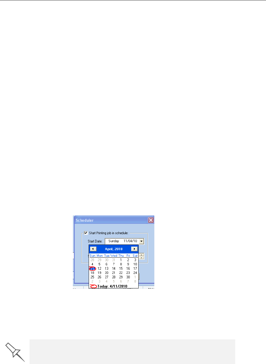
Using Objet Studio
5–70
DOC-07000 Rev. A
RestartingJobs
YoucanrestartjobsfromtheJobsQueueandtheHistorylist.
To restart a job:
1. Selectthejob.
2. ClicktheRestarticon.
Thejobstatuschangesto“Waiting”(intheJobsQueue).
ResumingJobs
Iftheprintingprocessisstoppedorinterrupted,youmaybeableto
continueprintingthejobfromthepointwhereprintingstopped.
To resume a job:
1. Selectthejob.
2. ClicktheResumeicon.
SchedulingJobs
Youcanschedulejobstobeprintedatafuturetime.Forexample,youcan
configureObjetStudiotostartlongprintingjobsinthelateeveningand
earlymorninghours.
To schedule a job:
1. SelectajobintheJobsQueue,andclickonthepop‐uptoolbar.
2. IntheSchedulerdialogbox,settheStartDateandStartTimeforthejob.
ClickontheStartDatearrowtoopenacalendar.
Figure 5-71: Scheduler with calendar displayed
3. ClickOK.
ExportingJobs(objzf)
Youcansaveprintjobsascompressedfiles.
Toexportaprintjob:
1. Selectajob.
2. Onthepop‐uptoolbar,click.
3. IntheSaveAsdialogbox,selectafolder.
For an explanation of objzf files, see “Exporting and Importing Objet Build
Trays” on page 63.

DOC-07000 Rev. A 5–71
Objet500 - Connex 3 User Guide
4. ClickSave.
ModifyingtheJobManagerScreen
YoucanchangethesizeofthesectionsoftheJobManagerscreen,by
draggingthepaneledges.Thisappliesto:
•theJobsQueuepanel
•theTimepanel
•theHistorypanel
Similarly,youcanchangethewaythescreenareaisdividedbetweenthe
mainsection(JobsQueue/Time/History)andthepanelsontherightsideof
thescreen.
Youcancollapse(hide)therightpanels(AvailableResources/Material
Consumption/TrayView)byclickingthetopofthepanel.
•Clickagaintodisplaythepanel.

Using Objet Studio
5–72
DOC-07000 Rev. A

DOC-07000 Rev. A 6–1
Operating & Maintaining the
Objet500 - Connex 3
3D
Printer
StartingthePrinter.............................................................................. 2
LoadingModelandSupportCartridges.......................................... 4
ProducingModels ............................................................................... 5
PrinterInterfaceColor Key.................................................................. 7
PrintingIndicators ................................................................................ 8
ResumingProductionAfterPrintinghasStopped......................... 9
ChangingtheModelMaterial ......................................................... 11
KeepingthePrinterinIdleMode ................................................... 14
ShuttingDownthePrinter............................................................... 15
MaintainingthePrinter .................................................................... 17
RoutineMaintenanceSchedule......................................................... 17
CleaningthePrintHeads................................................................... 18
PatternTest........................................................................................... 20
ImprovingPrintQuality .................................................................... 21
(see“ReplacingPrint Heads”onpage 6‐139)Cleaningand
ReplacingtheWiper ........................................................................... 22
CleaningtheRollerWasteCollectorandInspectingtheRoller
Scraper .................................................................................................. 24
ReplacingtheRollerScraper ............................................................. 27
AligningthePrintHeads ................................................................... 29
CalibratingPrintHeads ..................................................................... 33
ReplacingPrint Heads...................................................................... 139
TestingandCalibratingtheUVLamps ......................................... 190
CalibratingtheLoadCells ................................................................. 36
ReplacingtheOdorFilter................................................................... 35
ReplacingtheUVLamp ..................................................................... 35
Built‐inTests....................................................................................... 223
ReplacingtheWasteContainer ......................................................... 36
CleaningtheExteriorPanels ............................................................. 37
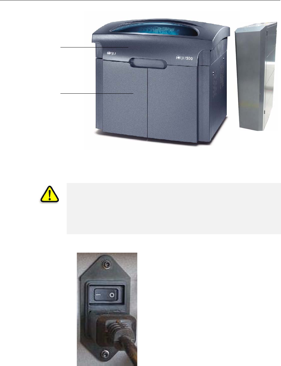
Operating & Maintaining the Objet500 - Connex 3 3D Printer
6–2
DOC-07000 Rev. A
Figure 6-1: The Objet500 - Connex 3 3-D Printer
Starting the Printer
1. Turnonthemainpowerswitch,locatedatthebackoftheprinter.
Figure 6-2: Main power cable and switch
ThemainpowerswitchturnsontheObjetprinter,whichincludesthe
built‐incomputer.
Printer cover
Storage
compartment
Materials
cabinet
CAUTION!
•Do not attempt to operate the Objet printer before being trained by an
Objet customer-support representative.
•Observe all safety warnings and follow the safety guidelines described
in chapter 2.
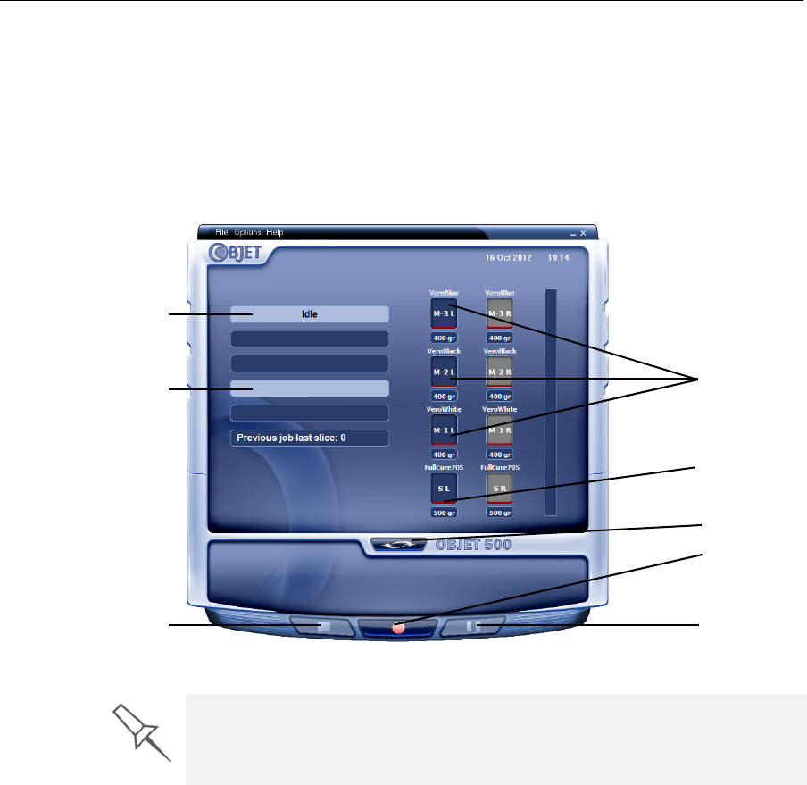
DOC-07000 Rev. A 6–3
Objet500 - Connex 3 User Guide
2. Afterthecomputerboots,logintoWindowsandlaunchtheprinter‐
controlapplication:
•Onthecomputerdesktop,double‐clicktheObjetprintericon.
or—
•FromtheStartmenu,selectObjet > Objet500.
TheObjetprinterinterfacescreenopens(seefigure 6‐2).Allmonitoring
andcontrollingoftheprinterisdonefromthisinterface.
Figure 6-3: Objet500 - Connex 3 interface
Printer mode
Current activity
Display
toggle button
Pause button
Stop button
Online/offline
button
Model material
cartridges
Support material
cartridges
Objet installations utilize one monitor for displaying both the computer
running Objet Studio and the computer installed inside the printer. Make
sure that the KVM (keyboard-video-mouse) switch is in the correct position
so that the printer interface is displayed.

Operating & Maintaining the Objet500 - Connex 3 3D Printer
6–4
DOC-07000 Rev. A
Loading Model and Support Cartridges
Objet500‐Connex3printersusesixcartridgesofmodelmaterialandtwo
cartridgesofsupportmaterial,eachweighing3.6kilogramswhenfull.A
graphicalrepresentationofthecartridgesloadedandtheircurrentweight
appearsintheprinter interface(seefigure 6‐3).
Important: Ifyouneedtoreplacethemodelmaterialcurrently
installedwithanothertype,see“ChangingtheModelMaterial”
onpage 6‐11.Otherwise,makesuretoreplacethemodel
cartridgewithonecontainingthesametypeofmaterial.
To load model and support cartridges:
1. Openthedoorofthematerialscabinet.
2. Ifyouarereplacingacartridge,graspitshandleandpullthecartridge
out,takingcarenottotwistorturnit.
3. Loadmodelandsupportcartridgesintotheirrespective
compartments.
Youshouldfeelsomeresistance,asaneedlepiercesthecartridge.
4. Checktheprinterinterfacetomakesurethatthenewcartridgeis
detectedandthatitsweightisdisplayed(seefigure 6‐3).
5. Closethematerialscabinet.
The materials cabinet uses RFID technology to automatically identify
cartridges of printing material. For this purpose, an RFID module is built into
the cabinet. Tampering with this module will render the printer inoperable
and may void Objet warranties and service contracts.
Tips about replacing cartridges:
•You can replace material cartridges either before or during printing.
•If printing stops for an extended time before you replace a material
cartridge, the printer may go into Standby or Idle mode. If this happens,
see “Resuming Production After Printing has Stopped” on page 9.
•You can replace partially used cartridges to avoid the need for replacing
them during printing.
•You can load partially used cartridges, as long as they contain more
than 100 grams of material.
DOC-07000 Rev. A 6–5
Objet500 - Connex 3 User Guide
Producing Models
TheObjet500‐Connex3printerproducesmodelsbyprintingtrayfiles
preparedintheObjetStudioapplicationandsenttotheprinterfromthere.
Forinformationaboutpreparingmodelfilesforprinting,see“UsingObjet
Studio”orObjetStudioHelp.
To prepare the printer for producing models:
1. Makesurethatthebuildtrayintheprinterisemptyandclean.Ifnot,
removeoldmaterialwiththescraper,andcleanthetraythoroughly
withcleaningfluid.
2. Makesurethatthereissufficientmodelandsupportmaterialloaded,
asindicatedintheprinterinterface(seefigure 6‐2).Youmaywantto
replacethecartridgesofmodelandsupportmaterialcurrentlyloaded
intheprintertoavoidtheneedforreplacingthemduringprinting.
3. Atthebottomoftheprinterinterface,clicktheredbuttontoswitchthe
printertoonlinemode.
Thecolorofthebuttonchangesfromredtogreen(seefigure 6‐3).If
thereisajobintheJobManagerqueue,itissenttotheprinter.
Intheprinterinterface,theprintermodechangesfromIdletoPre‐print,as
theprinter’scomponentspreparethemselvesforproduction:
•Theprintblockisheated.
•TheUVlampsarepoweredandtheywarmup.
Whenprintingbegins,ObjetStudiosendssevenslicestotheprinter.Thisis
thestandardbufferbetweenObjetStudioandtheprinter.Aseachsliceis
printed,anothersliceissenttotheprinter.
Dependingonthesizeofthemodel(s)tobeproduced,printingcantake
betweenseveralhourstoseveraldays.Aslongasthereisenoughmodel
andsupportmaterialinthesupplycartridges,printingproceeds
automaticallyuntilthejobisfinished.
Before beginning to produce models, it is recommended that you check the
current printing quality of the print heads by performing a pattern test (see
“Pattern Test” on page 20).
CAUTION: Use protective gloves when cleaning the build tray, and be
careful of the sharp edges of the scraper blade.
Forinstallingmaterialcartridgesandreplacingemptyones,see
“LoadingModelandSupportCartridges”onpage 6‐4.
Forchangingthetypeofmodelmaterialcurrentlyloaded,see
“ChangingtheModelMaterial”onpage 11.
During printing, the server computer must remain on and it must
communicate with the Objet printer. Do not log-off Windows until printing is
finished.
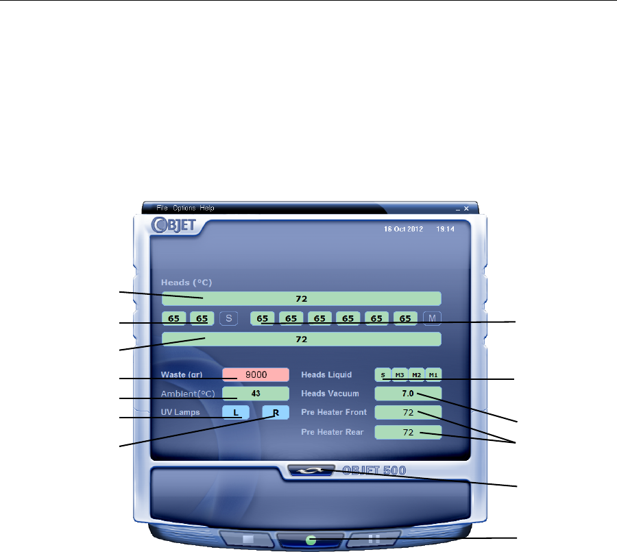
Operating & Maintaining the Objet500 - Connex 3 3D Printer
6–6
DOC-07000 Rev. A
TheObjet500‐Connex3printerusesoneormoremodel‐material
cartridgesandonesupport‐materialcartridgetoproducemodels.If
additionalcartridgesareinstalledandtheyarenotneededforthecurrent
printjob,theprinterinterfaceindicateswhicharebeingused:
•Bluecartridge—usedfortheprintjob
•Graycartridge—notusedfortheprintjob
Youcanmonitorprinterstatusindicatorsbyswitchingtheprinterinterface
display.Todothis,clickthedisplaytogglebuttonintheprinterinterface
screen.
Figure 6-4: Printer indicators
Temperature.
in front of
print block
Temperature
behind
print block
Waste weight
Display
toggle button
Printer set to
online mode
(green)
Temp. of each
support head
Chamber temp.
Left UV lamp
Right UV lamp
Temp. of each
model head
Support/Model
material in print-
block reservoir
System
vacuum level
Temp. of material
pre-heaters

DOC-07000 Rev. A 6–7
Objet500 - Connex 3 User Guide
Printer
Interface
Color Key
Thebackgroundcolorsintheprinterindicatorfieldstellyouataglance
whetherornotthevalueoritemissuitableorreadyforprinting.
•Green—suitable/readyforprinting
Forexample,infigure 6‐3:
Heads(°C)—Theheadshavereachedthetemperaturerequiredfor
printingmodels.
Ambient—Theambienttemperatureoftheprintingchamberis
withintheacceptablerange.
HeadsLiquid—Thelevelofmodelandsupportmaterialintheprint‐
blockreservoirisOK.
Vacuum—Thevacuumlevelinthesystemiswithintheacceptable
range.
•Red—notsuitableforprinting(orindicatesawarning)
Forexample,infigure 6‐3:
Waste—Theweightofthewastecontaineris9000grams,morethan
allowedwhenbeginningaprintjob.(See“ReplacingtheWaste
Container”onpage 6‐36.)
•Blue—notready
Forexample,infigure 6‐3:
UVlamp—TheUVlampsarenoton.
Thecolorofthematerialcartridgesdisplayedintheprinterinterface
indicateswhichcartridgesareactiveforthecurrent(ornext)printjob.
•Blue—activecartridges
•Gray—reservecartridges
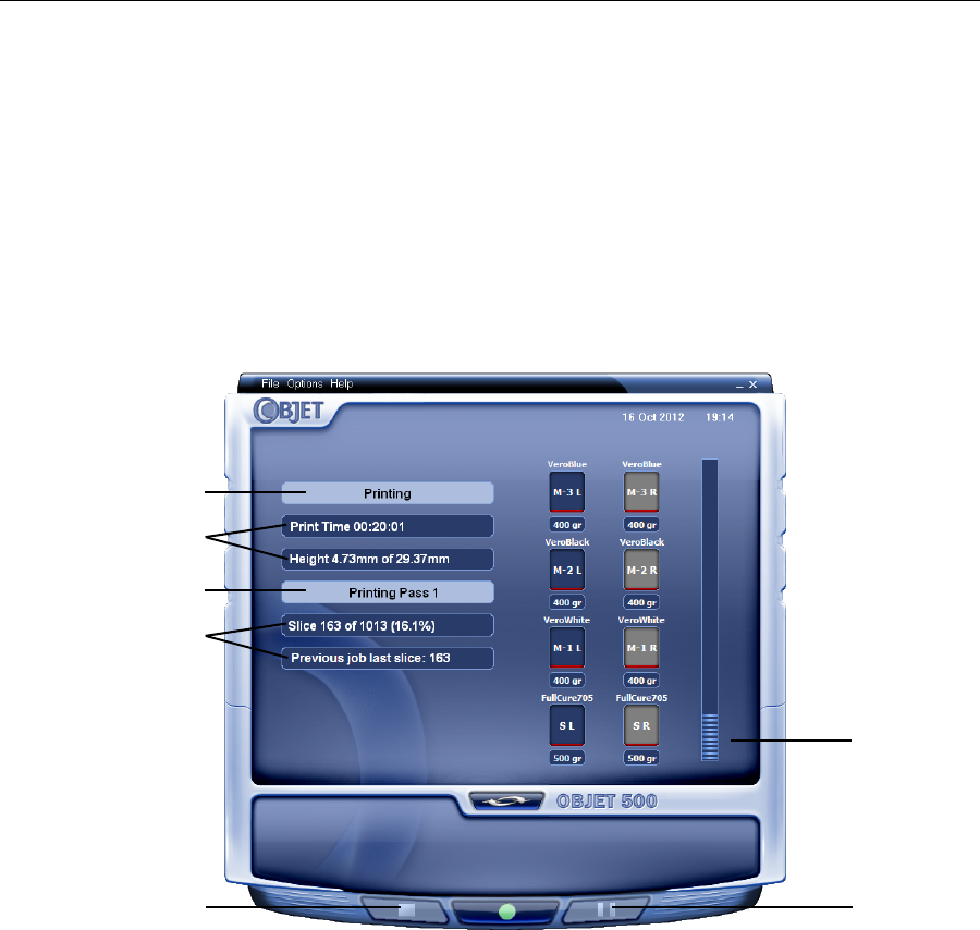
Operating & Maintaining the Objet500 - Connex 3 3D Printer
6–8
DOC-07000 Rev. A
Printing
Indicators TheprinterinterfacescreenchangeswhenyousendaprintjobfromObjet
Studiototheprinter,andtheprinterisonline(seefigure 6‐4):
•ThemodechangesfromPre‐printtoPrinting.
•Thespecificactivitybeingperformedisshowninthe“currentactivity”
field.
•Currentjob‐printinginformationisdisplayed.
•Theprintingprogressbarisdisplayed.
•TheStopandPausebuttonsareenabled.
Whentheweightofacartridgedropsbelow100grams,thedisplayofthe
materiallevelintheprinterinterfaceisred.
Figure 6-5: Printer interface during printing
Progress bar
Pause button
Stop button
Printer mode
Job information
Job information
Current Activity
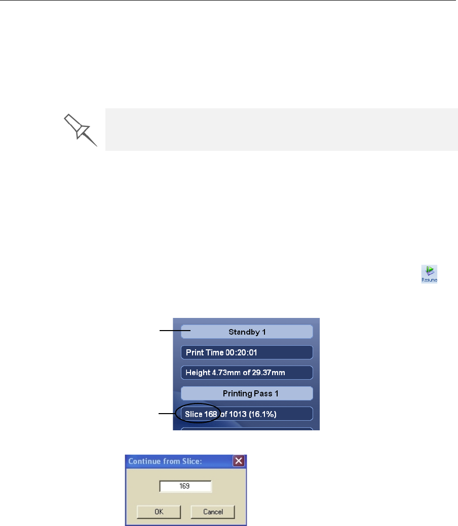
DOC-07000 Rev. A 6–9
Objet500 - Connex 3 User Guide
Resuming Production After Printing has Stopped
Iftheprintingprocessisinterrupted,ObjetStudiostopssendingslicesto
theprinter.Thiscanhappen,forexample,iftheprintingmaterialrunsout
inthemiddleofaprintjob,andyoudon’treplacetheemptycartridge
immediately.AftertheprinterchangestoStandbyorIdlemode,youneedto
resumeprintingfromtheJobManagerscreenofObjetStudio.
To continue printing the model:
1. Iftheprinterisinofflinemode,switchittoonlinemodebyclickingthe
redbuttonatthebottomoftheprinterinterface(seefigure 6‐2on
page 6‐3).
Thebuttonchangesfromredtogreen(seefigure 6‐3onpage 6‐6).
2. Ifyoudon’tknowwhyprintinghasstopped,makesurethatthe
connectionbetweentheprinterandtheservercomputerisactive.
3. IntheJobManagerscreenofObjetStudio,clicktheResumeicon.
4. IntheContinuefromSlicedialogboxthatappears,confirmtheslice
number,aftercheckingtheprinterinterface.
Figure 6-6: Printer interface after interrupted printing
Figure 6-7: Continue from Slice confirmation in Objet Studio (Job Manager
screen)
5. If,foranyreason,thecorrectnumberdoesnotappearinthedialog
box,enterthenumberandclickOK.
Youcannotcontinueprintingthemodelif:
•Thenumberofthelastsliceprinteddoesnotappearintheprinter
interface,eveniftheservercomputerdisplaystheContinuefromSlice
confirmationdialogbox.
•Therewasarelativelylonginterruptioninprinting,evenifthe“last
slice”and“continuefromslice”indicatorsarecorrect.Thepartofthe
modelalreadyprintedmaydeformorshrink,andtheremightbea
visibledifferencebetweenitandthenewlyprintedpart.Theeffectsofa
After printing stops, the printer goes into Standby mode, when heating of
print heads is reduced. About 10 hours later, the printer goes into Idle mode,
when heating of print heads is stopped.
Printer mode
Last slice printed

Operating & Maintaining the Objet500 - Connex 3 3D Printer
6–10
DOC-07000 Rev. A
printingstoppageonamodeldependonthemodelsizeandstructure,
modelmaterialused,ambienttemperatureandthelengthofthe
stoppage.
If you cannot continue printing:
1. CanceltheprintjobintheJobManagerscreen.
2. Removethepartiallyprintedmodelfromthebuildtray.
3. Sendthejobtotheprinteragain.
You can stop and later resume printing from either the printer interface or
from the Job Manager screen of Objet Studio, since both applications are
updated when you use these commands. However, after clicking the Pause
button in the printer interface, you can only resume printing from the printer
interface.
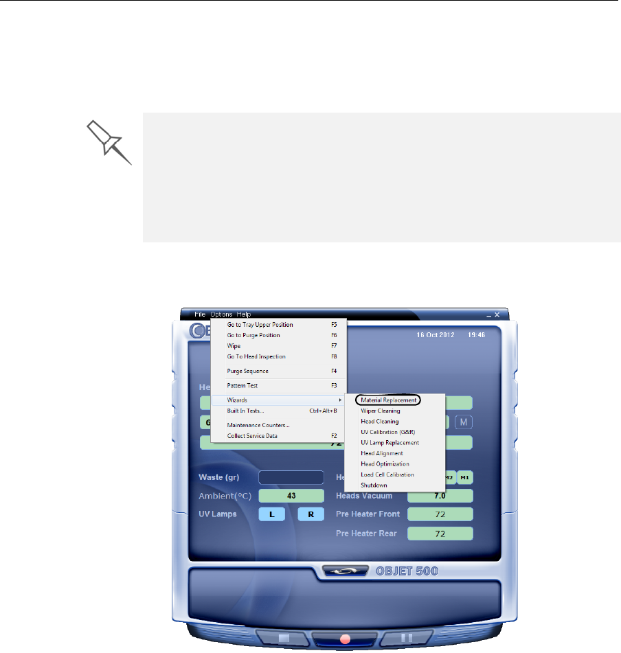
DOC-07000 Rev. A 6–11
Objet500 - Connex 3 User Guide
Changing the Model Material
Beforeproducingmodelsusingadifferenttypeofmodelmaterialthanis
currentlyinstalled,runtheMaterialReplacementWizardtoflushtheprint
blockandfeedtubes.
To replace the model material:
1. StarttheMaterialReplacementWizardfromtheOptionsmenu.
Figure 6-8: Starting the Material Replacement Wizard from the Options menu
2. Intheopeningscreen,clickNext
You should carefully plan printing models with different model materials to
avoid unnecessary waste of material currently loaded. The amount of
material flushed depends on the flushing cycle chosen and if you are
replacing one or more materials.
The Material Replacement Wizard suggests the best slot locations for
placing different material cartridges, based on materials in the system. This
ensures minimum flushing of materials currently loaded.
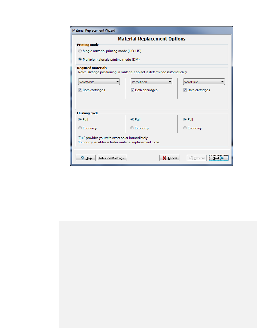
Operating & Maintaining the Objet500 - Connex 3 3D Printer
6–12
DOC-07000 Rev. A
3. Iftheprintercoverisnotclosed,ascreenappearsinstructingyouto
closethecover.ConfirmthatitisclosedandclickNext.
Figure 6-9: Material Replacement Options
IntheMaterialReplacementOptionsscreen,youselectthesettingsthat
determinehowthewizardreplacesmaterialcurrentlyinthesystem
withnewlyloadedmaterial.
4. ChoosewhetheryouwanttoproducemodelsinSingleMaterialmode
orinDigitalMaterial(“multiple‐materials”)mode.
5. IntheRequiredmaterialssectionofthewizardscreen,selectoneormore
replacementmaterials.
6. SelectBoth cartridgesifyouneedtoloadtworeplacementcartridges.
Loadingonereplacementcartridge(ifsufficient)ismoreeconomical
becauseitpotentiallyrequireslessflushingofmaterialcurrentlyinthe
system.
•Single Material mode
Fourprintheadsareusedtoprint,usingonemodelmaterial.
ThismodeisrequiredtoproducebuildtrayswiththeHighQuality
setting,andtoproducetrayswiththeHighSpeedsettingusingonly
onemodelmaterial.
•Digital Material mode
Eachofthemodelmaterialsloadedisusedintwooftheprintheads.
Ifonlyoneofthemodelmaterialsisrequiredforprinting,models
areproducedusingtwoprintheads.Thismakesitunnecessaryto
replacetheothermodelmaterial.
Ifmodel‐materialsubstitutionisallowed,theprinterproducestrays
withtheHighSpeedsettingusingamixtureofmodelmaterials(see
“ModelMaterialSubstitution”onpage 5‐112).
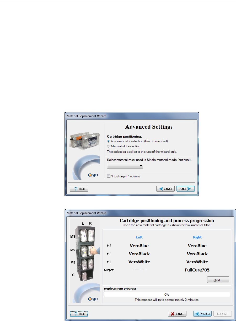
DOC-07000 Rev. A 6–13
Objet500 - Connex 3 User Guide
7. IntheFlushingcyclesectionofthewizardscreen,choosehow
thoroughlyyouwanttoflushoutmaterialcurrentlyinthesystem.
•Economy.Thiscyclecanbeusedwhenreplacingalight‐colored
modelmaterialwithadarkermaterial(suchasTangoBlack™or
VeroBlack™),oriftheexactcoloroftheprintedmodelsis
unimportant.
Thewizardflushesthesystemwiththeminimumamountof
materialneededtoensurethatmodelshavethemechanical
propertiesofthenewmaterial.
•Full.Usethiscyclewhentheprintedmodelsmusthavetheexact
colorofthenewmaterial.
Thewizardthoroughlyflushesthefeedtubesandprintheads
neededforprinting,basedonyourselectionsintheprevious
screens.
Figure 6-10: Advanced Replacement settings
Figure 6-11: Cartridge insertion
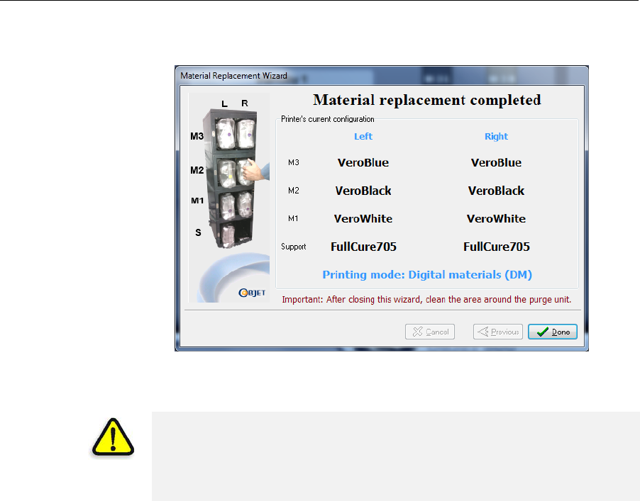
Operating & Maintaining the Objet500 - Connex 3 3D Printer
6–14
DOC-07000 Rev. A
8. Whenthefinalwizardscreenappears,makesurethatthescreen
displaysthenewly‐loadedmaterial(s).ClickDonetoclosethewizard.
Figure 6-12: Results of material replacement
Theprinter‐controlinterfaceisautomaticallyupdated,andshould
displaythenewmaterial(s).TheObjetStudiointerface(ontheprinter‐
serverworkstation)isalsoupdated.
CAUTION: Dispose of all material cartridges in accordance with all
applicable laws and regulations. If necessary, the cartridges can be
disassembled for recycling. If this is done, protect the person handling
the cartridges from direct exposure to uncured resins.
DOC-07000 Rev. A 6–15
Objet500 - Connex 3 User Guide
Keeping the Printer in Idle Mode
Betweenprintingjobs,theObjet500‐Connex3printercanbekeptonforup
tooneweek.Iftheprinterwillnotbeusedformorethanaweek,usethe
ShutdownWizardtoautomaticallyperformtheproceduresthatmustbe
donebeforeturningofftheprinter(see“ShuttingDownthePrinter,”
below).
Whentheprinterstopsproducingmodels,theprintersoftware
automaticallyreducesthetemperatureoftheprintheadsasfollows:
Note: The printer mode is indicated in the green field on the left of the
interface (see figures 6-2, 6-3 and 6-4 on pages 3, 6 and 8).
If,afterprintingajob,youknowthattheprinterwillnotbeusedfor10
hoursormore,youcanimmediatelyturnofftheheatingoftheprintheads
byputtingtheprinterintoIdlemode.
To put the printer into Idle mode:
¾FromtheFilemenu(intheprinterinterface)clickExit.
Note: The printer remains in Idle mode until you open the Objet printer
application and begin printing again.
Time after printing Mode Change in heating of print heads
first15minutes Standby1none
next10hours Standby2heatingreduced(toroomtemp.)
after10hours Idle heatingstopped
When the printer is in Idle mode, do not turn it off. It can remain in this
mode—with the cover closed—for up to a week. For longer periods, shut
down the printer by running the Shutdown Wizard (see below).
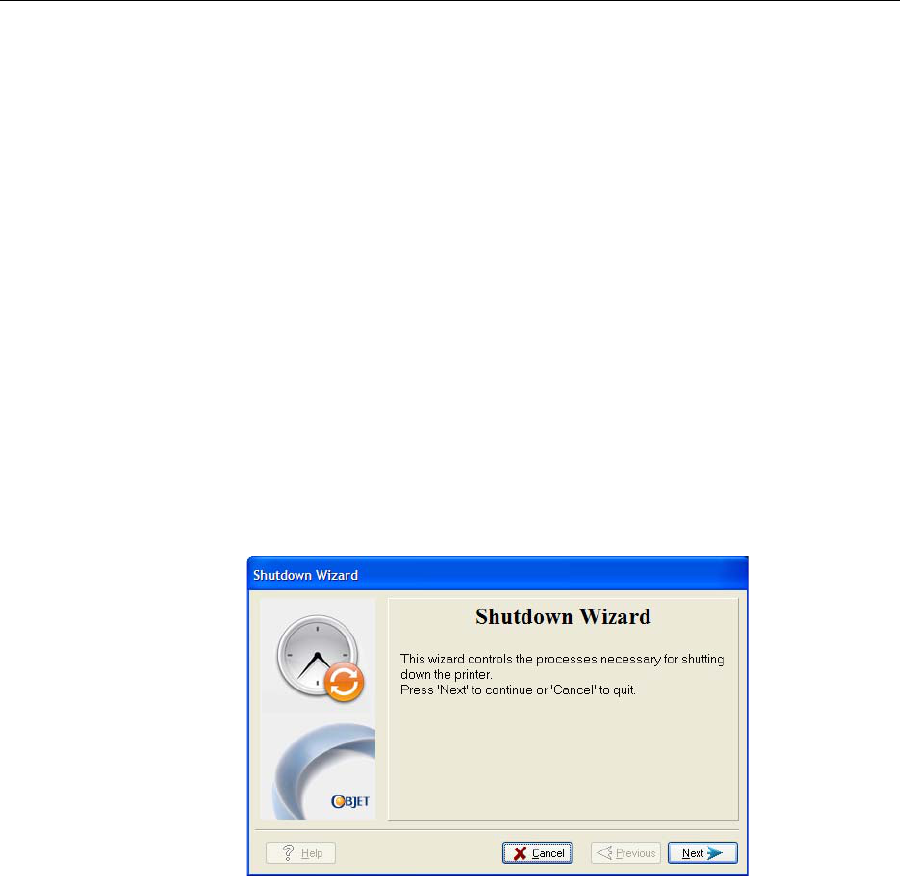
Operating & Maintaining the Objet500 - Connex 3 3D Printer
6–16
DOC-07000 Rev. A
Shutting Down the Printer
YouonlyneedtoshutdowntheObjetprinterifitwillnotbeusedfora
weekormore.Otherwise,theprintercanremainon,inIdlemode.To
properlyshutdown,theprinterneedstoperformseveralprocesses.These
arecontrolledbytheShutdownWizard.Donotattempttoshutdownthe
printerbysimplyclosingthecomputerinterface(theprinter‐control
application),andneverdisconnectpowertotheprinterbefore
completingthiswizard.
Dependingonthelengthoftimetheprinterwillnotbeused,youcan
choosebetweenashortshutdownprocedure,andamorethorough
procedure.
•Upto10days:Thewizardemptiestheprintblockofmodeland
supportmaterial,topreventleaks.Thistakesabout10minutes.
•Morethan10days:Thewizardemptiestheprintblock,thenflushes
thesystemwithcleaningfluid.Thistakesupto35minutes,andyou
mustbepresenttoloadcleaning‐fluidcartridgeswheninstructed.
To run the Shutdown Wizard:
1. SelectShutdown fromtheOptionsmenu,orpressF8.
Figure 6-13: Shutdown Wizard, opening dialog box
2. Intheopeningwizardscreen,clickNext.
3. Choosetheappropriateoptionforthelengthoftimethattheprinter
willnotbeused—lessormorethantendays.
Note: Before selecting More than 10 days, make sure that cleaning-fluid
cartridges are available.
4. Inthenextscreen,verifythatthetrayisemptyandclickNext.
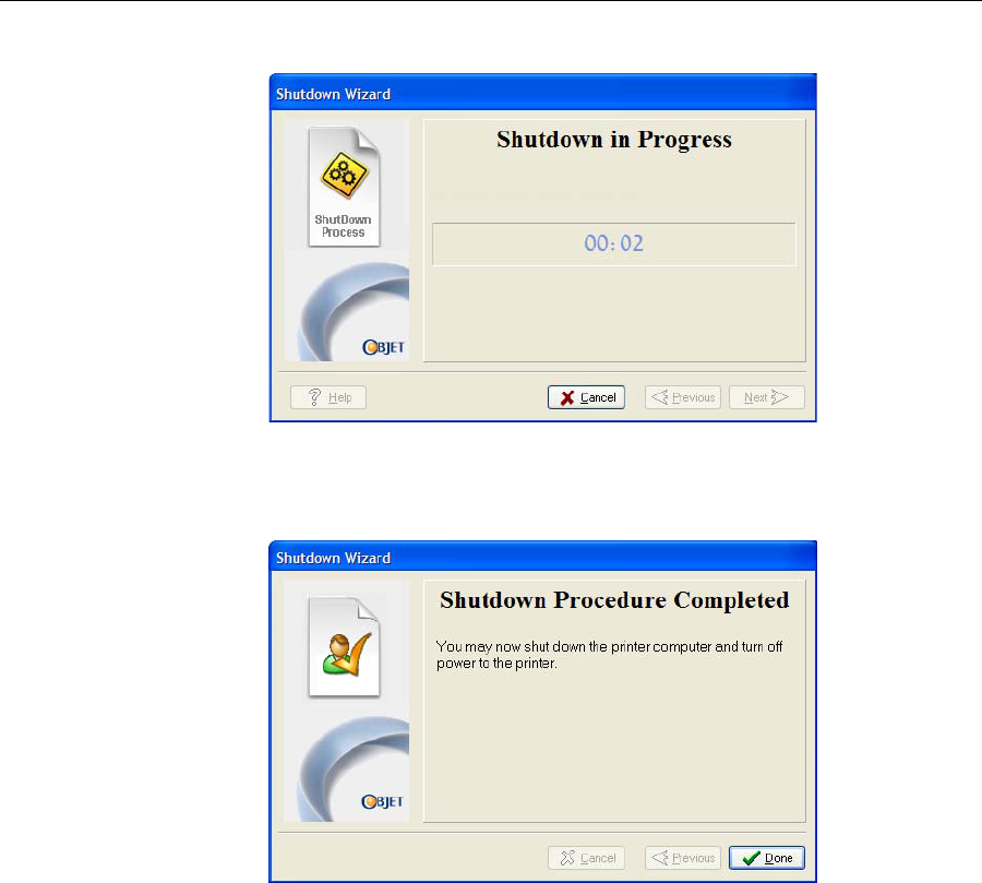
DOC-07000 Rev. A 6–17
Objet500 - Connex 3 User Guide
Theshutdownprocedurebegins.
Figure 6-14: Shutdown progress screen
5. Whenthefinalwizardscreenappears,closetheprinter‐control
applicationandshutdownthebuilt‐incomputer.
Figure 6-15: Final Shutdown Wizard screen
6. Aftertheprintercomputershutsdown,turnoffthemainpowerswitch
atthebackoftheprinter(seefigure 6‐2onpage 6‐2).

Operating & Maintaining the Objet500 - Connex 3 3D Printer
6–18
DOC-07000 Rev. A
Maintaining the Printer
Theperformanceofroutinemaintenancetasksisessentialforgetting
satisfactoryresultsfromObjet3‐Dprinters.Performthetasksatspecified
intervalsforoptimumperformance.
Routine
Maintenance
Schedule
Frequency Task For More Information
Daily,beforeprinting Cleantheprintheads. See“CleaningthePrint
Heads”onpage 6‐18.
WeeklyCleanthebuildtrayand
thesurroundingarea.
Weekly PerformthePatterntest. See“PatternTest”on
page 6‐20.
Weekly Cleanandinspectthe
wiper. See“(see“Replacing
Print Heads”on
page 6‐139)Cleaning
andReplacingthe
Wiper”onpage 6‐22.
Weekly Restarttheprinter
computerandthe
server computer.
Weekly Cleantherollerwaste
collector. See“CleaningtheRoller
WasteCollectorand
InspectingtheRoller
Scraper”onpage 6‐24.
Every300hoursof
printing(Areminder
messageappears.)
TesttheUVlamps. See“Testingand
CalibratingtheUV
Lamps”onpage 190.
Monthly,andafter
replacingprintheads Checkthealignmentof
theprintheads. See“AligningthePrint
Heads”onpage 6‐29.
MonthlyCalibratetheloadcells. See“Calibratingthe
LoadCells”on
page 6‐36.
Monthly Inspecttheexhaust
system(duct,fan,
connections).
Every2000hoursof
printing,oronceayear
Preventivemaintenance
visitbyauthorized
serviceengineer.
ContactyourObjet
supportcenter.
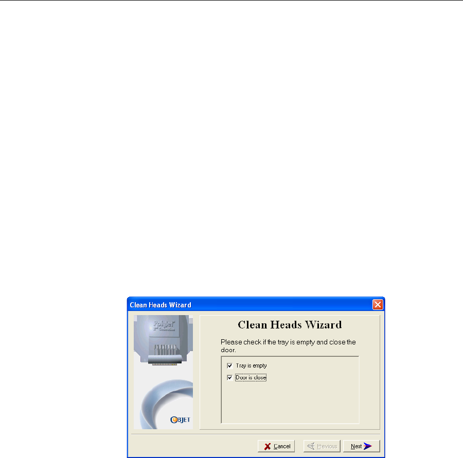
DOC-07000 Rev. A 6–19
Objet500 - Connex 3 User Guide
Cleaning the
Print Heads Periodicinspectionandcleaningoftheorificeplatesonthebottomofthe
printblockensuresthattheprintnozzlesarenotclogged.Awizardguides
youthroughtheprocedure,andadjustscomponentsoftheprinterto
enableyoutoperformit.Thisproceduretakesabout20minutes,and
shouldbedoneatthebeginningoftheworkdayorbeforeabigprinting
job.
To clean the print heads:
1. Prepare—
•isopropanol(IPA—isopropylalcohol)orethanol(ethylalcohol)
•disposablecleaninggloves
•anObjet‐suppliedcleaningclothorequivalent
•amirror
2. StarttheHeadCleaningWizardfromtheOptionsmenuoftheprinter
interface(seefigure 6‐22onpage 6‐22).
3. Followtheinstructionsonthewizardscreens,andselectthecheck
boxestoconfirmthat:
•youhavecheckedthatthetrayisempty.
•youhaveclosedthecover.
Figure 6-16: Head cleaning procedure—wizard screen
4. ClickNext.
Theprinterpreparesforyoutocleantheprintheads.
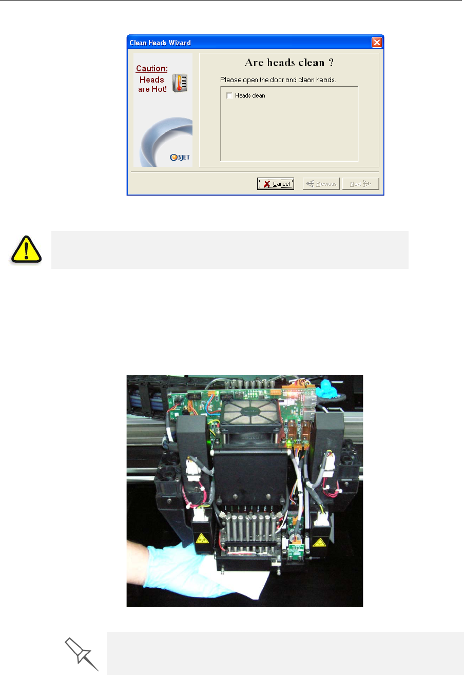
Operating & Maintaining the Objet500 - Connex 3 3D Printer
6–20
DOC-07000 Rev. A
5. Whenthefollowingscreenappears,openthecover.
Figure 6-17: Head cleaning wizard—steps 5–10
6. Placethemirroronthebuildtray.
7. Putonthegloves.
8. Soakthecleaningclothwiththecleaningfluid.
9. Cleantheorificeplates,withaback‐and‐forthmotion(seefigure 6‐17).
Usethemirrortomakesurethatyouhaveremovedalloftheresidue
material.
Figure 6-18: Cleaning the heads
10. Whenyouhavefinishedcleaning,selecttheconfirmationcheckboxin
thewizardscreen(seefigure 6‐16)andclickNext.
WARNING: The print head orifice plates (bottom surface) may be hot.
Do not touch them with your bare hands, and proceed with caution.
It is recommended that you use this opportunity to also clean the roller and
the UV lamps.
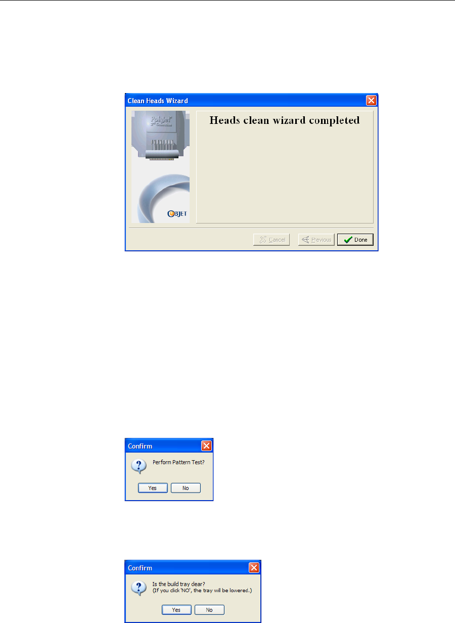
DOC-07000 Rev. A 6–21
Objet500 - Connex 3 User Guide
11. Removethecleaningmaterialsfromtheprinterandclosethecover.
12. Selecttheconfirmationcheckboxesinthewizardscreenandclick
Next.
Thehead‐purgecyclebegins.Whenthisiscomplete,thefinalwizard
screenappears.
Figure 6-19: Head-cleaning wizard—final screen
13. ClickDonetoclosethewizard.
Pattern Test Thepatterntestisthebasicverificationoftheprinter’sabilitytoproduce
qualitymodels,sinceitdemonstratestheconditionofthenozzlesinthe
printheads.Makesure,therefore,thatyouperformthistestweekly,and
wheneveryoususpectaprintingproblem.
To perform the pattern test:
1. Makesurethatthebuildtrayisempty.
2. Prepareasheetofpinkpaper—A‐4orLettersize.
3. Intheprinter,tapethepinkpapertothesurfaceleftofthebuildtray.
4. PressF3,oropentheOptionsmenuandselectPattern Test.
Figure 6-20: Pattern Test confirmation
5. Ifthebuildtrayisnotclear,clickNointhefollowingdialogbox.
Thislowersthebuildtray,sothatmodelsonthetrayarenotdamaged.
Figure 6-21: Build tray (Z) level adjustment
Theprinterprintsaseriesoflinesonthetestpaper(seenextfigure).
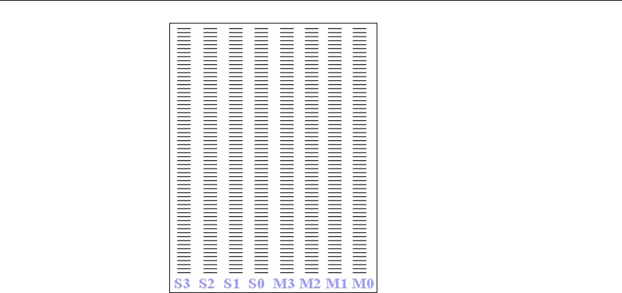
Operating & Maintaining the Objet500 - Connex 3 3D Printer
6–22
DOC-07000 Rev. A
Figure 6-22: Sample Pattern Test
6. Carefullyinspectthetestpapertoseeiftherearemissinglines.
Toomanymissinglines,especiallyiftheyareinthesamearea,
indicatesthatthequalityofprintingwhenproducingmodelswillbe
poor.Ifthisisthecase,see“ImprovingPrintQuality,”below.
Note: Acceptable model quality is subjective, and depends on the type
and scale (size) of the models produced. As a rule, however, more than 10
missing lines in one area of a column is considered unacceptable.
Improving
Print Quality Ifyoususpectthatprintqualityispoor,performthepatterntest(see
“PatternTest”onpage 6‐20).Iftheresultsarepoor,usethefollowing
proceduretoimproveprintquality.
If the results of the last pattern test are poor:
1. FromtheOptionsmenu,selectExecute Purge Sequence,orpressF4.
2. Intheconfirmationdialogbox,clickYes.
Theprintheadsarepurgedofmodelandsupportmaterial,andthe
wiperremovesexcessmaterialfromthem.
3. Repeatthepurgesequence.
4. Performthepatterntest.
If the results of the pattern test are still poor:
1. Manuallycleantheprintheads(see“CleaningthePrintHeads”on
page 6‐18).
2. Performthepurgesequence.
3. Performthepatterntest.
If the results of the pattern test are still poor:
1. Carefullycleantheprintheadsagain,makingsurethereisnoresidue
leftonthem.
2. Performthepurgesequence.
3. Performthepatterntest.
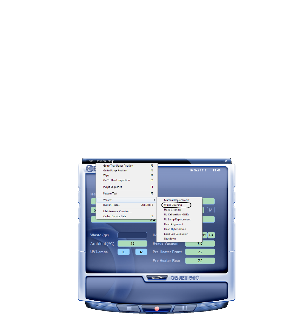
DOC-07000 Rev. A 6–23
Objet500 - Connex 3 User Guide
If the results of the pattern test are still poor:
¾Optimizetheprintheadsandreplacefaultyprintheads,ifnecessary
(see“CalibratingPrintHeads”onpage 6‐33).
Cleaning and
Replacing the
Wiper
Arubberwiperremovesexcessmaterialfromtheprintheadsafterthe
purgesequence.Thisisdoneautomaticallybeforeeachprintjob,and
performedmanuallyduringmaintenancetasks.Youshouldcleanthe
wiperandsurroundingareaatleastonceaweek.Ifthewiperisdamaged
orworn,replaceit.
To inspect and clean the wiper:
1. Prepare—
•isopropanol(IPA—isopropylalcohol)orethanol(ethylalcohol)
•disposablecleaninggloves
•anObjet‐suppliedcleaningclothorequivalent
•asparewiper
2. StarttheWiperCleaningWizardfromtheOptionsmenu.
Figure 6-23: Starting the Wiper Cleaning Wizard
3. Closetheprintercover,andclickNextinthewizardscreen.
4. Makesurethatthebuildtrayisempty,andclosetheprintercover.
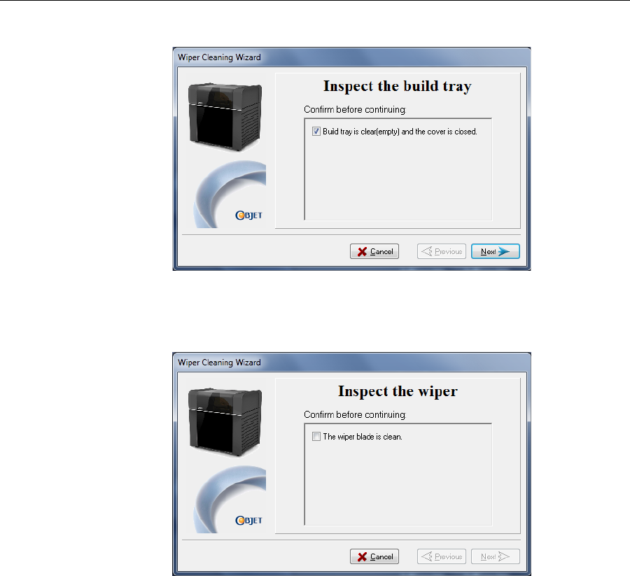
Operating & Maintaining the Objet500 - Connex 3 3D Printer
6–24
DOC-07000 Rev. A
Confirmthisinthewizardscreen.
Figure 6-24: Wiper Cleaning procedure—step 4
5. ClickNext.
6. Whenthefollowingscreenappears,openthecover.
Figure 6-25: Wiper Cleaning Wizard during steps 7–10
7. Putonthecleaninggloves.
8. Usingagenerousamountofcleaningfluidandthecleaningcloth,
removeanymaterialremainingonthewiperandthesurrounding
area.
9. Inspectthewiper.
Ifthewiperisscratched,tornorworn,orifyoucannotcleanit
completely,replaceit.
a. Graspitandpullitupandoutofitsbracket.
b. Insertthenewwiperblade,makingsurethatitisstraightandsecured
wellonbothsides.
10. Inthewizardscreen(seefigure 6‐24),confirmthatthewiperbladeis
clean,andclickNext.
11. Makesurethatyouhaveremovedalltoolsandcleaningmaterials
fromtheprinter,andclosethecover.
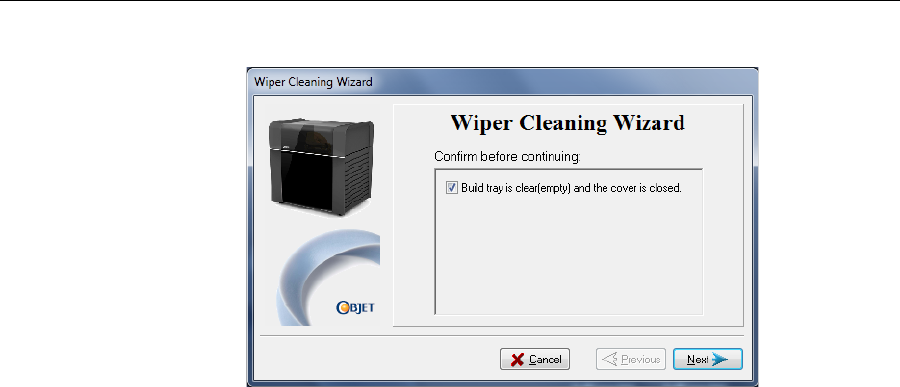
DOC-07000 Rev. A 6–25
Objet500 - Connex 3 User Guide
12. Confirmthatthetrayisclearandthatthecoverisclose,andclickNext.
13. ClickDonetoclosethewizard.
Cleaning the
Roller Waste
Collector and
Inspecting the
Roller Scraper
Therollerwastecollectorremoveswastematerialscrapedfromtheroller.
Suctionremovesthiswastetotheprinter’swastecontainer.
Thisassemblyshouldbecleanedweeklytopreventablockageinthetubes
leadingtothewastecontainer,sothatwastematerialdoesnotoverflow
intotheprinter.
To clean the roller waste collector:
1. Prepare—
•M2.5andM2Allenkeys
•disposablecleaninggloves
•isopropanol(IPA—isopropylalcohol)orethanol(ethylalcohol)
•cleaningcloth
•cottonswabs(Q‐tips®orsimilar)
2. Putonthegloves.
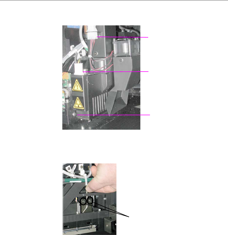
Operating & Maintaining the Objet500 - Connex 3 3D Printer
6–26
DOC-07000 Rev. A
3. RemovetherightUV‐lampassembly:
a. DisconnecttheUVpowercableandthefanpowercable.
Figure 6-26: Disconnecting the right UV assembly
b. RemovethescrewattachingtherightUVlamptotheprintblock,
andthenpullandliftuptheUVlamp.
4. Loosenthetwoscrewssecuringthesuctiontubeontheprintblock.
Figure 6-27: Lifting the suction tube
5. Liftthesuctiontubetosecureitinaraisedposition.
Fan power
connector
Power connector
Screw
Suction tube screws
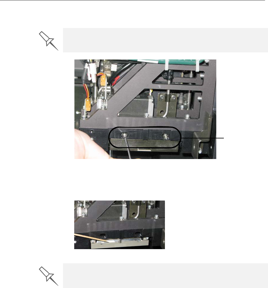
DOC-07000 Rev. A 6–27
Objet500 - Connex 3 User Guide
6. Removethetwoscrewssecuringthecoveringoftherollerwaste
collectorandremoveit.
Figure 6-28: Removing the roller waste collector covering
7. Removethecoveringbypullingitout,andthenlowerit.
8. Cleantherollerwastecollectorandthescraperbladesurfaceusing
cottonswabs.Makesuretoremoveanyremainingprintingmaterials.
Figure 6-29: Cleaning the roller waste collector
To check the effectiveness of the roller scraper:
1. Putonthecleaninggloves.
2. Wetaclothwithisopropanol.
3. Usetheclothtowetthebottomoftheroller.
4. Turntherollerslowlywithyourhand.Asthebladescrapestheroller,
makesuretheisopropanolisspreadevenlyovertheentirelengthof
theblade.
5. Inspecttheroller.Ifitisnotdry,replacetheblade.(See“Replacingthe
RollerScraper”onpage 6‐27.)
Be very careful to save the covering screws. These are special screws; if
they are lost you need to order replacements.
Roller waste
collector screws
Before replacing the covering you can check the effectiveness of the roller
scraper—see below.
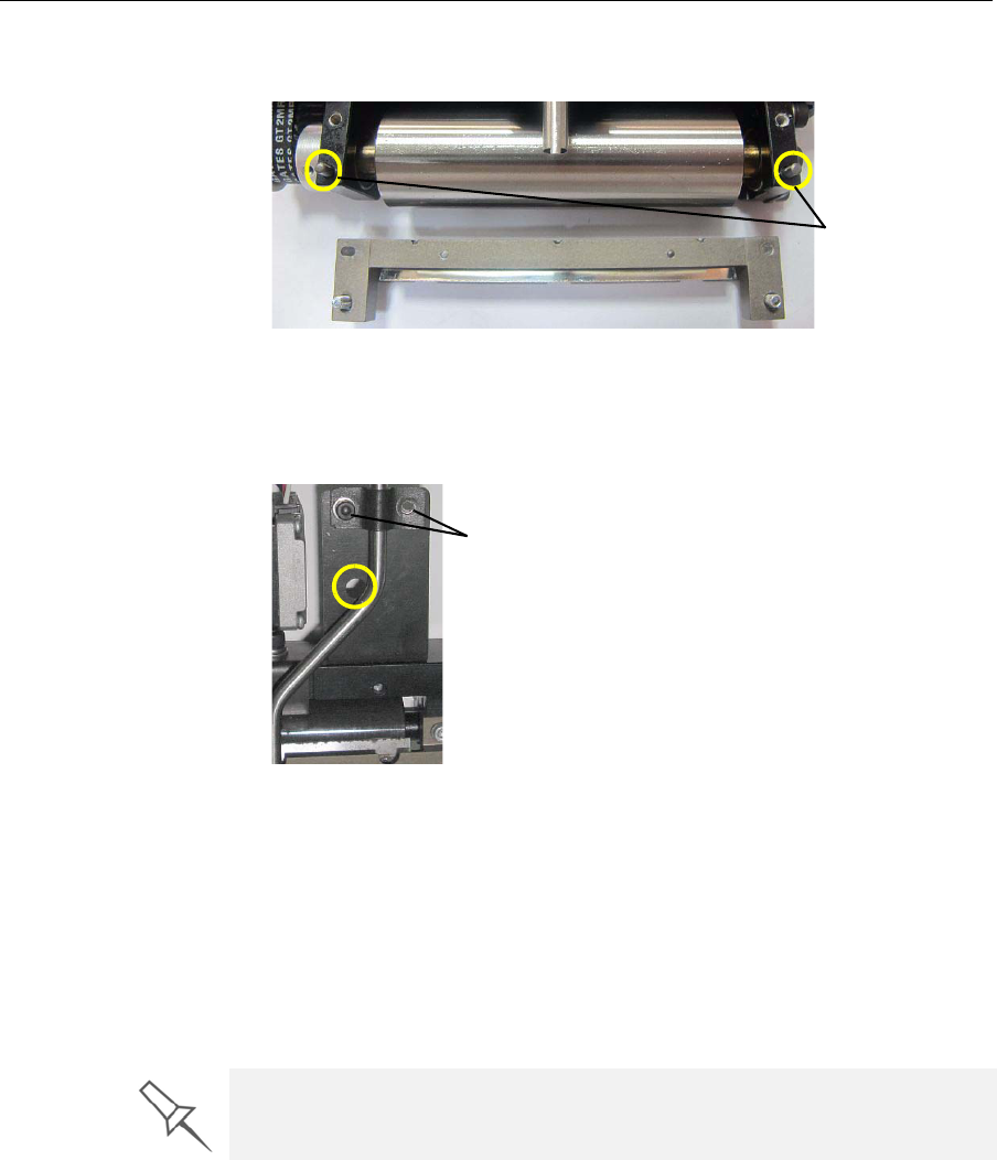
Operating & Maintaining the Objet500 - Connex 3 3D Printer
6–28
DOC-07000 Rev. A
6. Beforereturningtherollerwastecollectortotheprintblock,makesure
thatthepinsareclean.
Figure 6-30: Roller waste collector pins
7. Returntherollerwastecollectortotheprintblockandscrewonthe
covering(seefigure 6‐27onpage 6‐26).
8. Loosenthescrewssecuringthesuctiontube.
Figure 6-31: Suction tube correctly positioned
9. Loweritsothattheholeinthepanelbehindthesuctiontubeisvisible,
andtightenthescrewstosecurethetube.
10. Attachtheright‐UV‐lampassemblytotheprintblockandreconnect
theUVpowerandfancables.
Replacing the
Roller Scraper Youshouldreplacetherollerscraperblade:
•after1,000hoursofprinting.
•ifitdoesnoteffectivelykeeptherollerclean.
To replace the roller scraper:
1. Prepare—
•anewrollerscraper(knife)(KIT‐01026‐S)
•aPhillips1x75mmscrewdriver
•M2.5andM2Allenkeys
2. RemovetherightUVlampandtherollerwastecollectorcovering(see
steps3to6onpage 6‐25.)
Roller waste
collector pins
Securing screws
You should periodically test the effectiveness of the roller scraper when you
clean the roller waste collector. See “Cleaning the Roller Waste Collector
and Inspecting the Roller Scraper” on page 24..
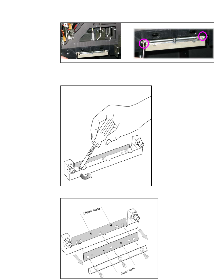
DOC-07000 Rev. A 6–29
Objet500 - Connex 3 User Guide
3. Loosenthetwoscrewssecuringtherollerwastecollectorandpullit
out.
Figure 6-32: Removing the roller waste collector
4. Removethescrewsthatsecuretherollerscraperassembly.
Figure 6-33: Removing the roller scraper screws
Figure 6-34: Removing the old roller scraper blade
5. Removethescraperbladeanddiscardit.
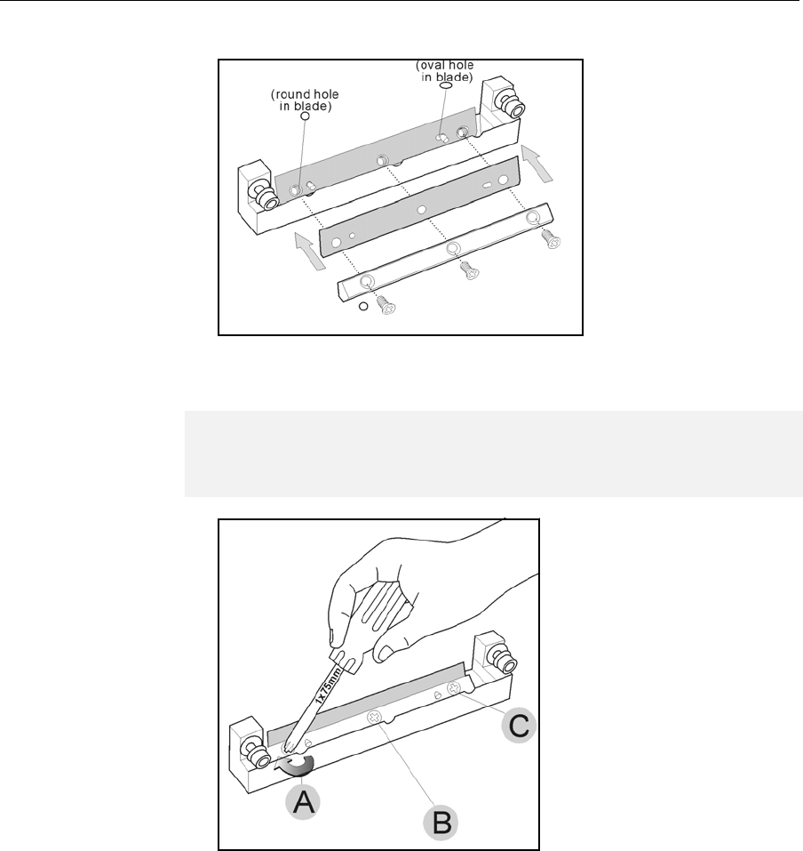
Operating & Maintaining the Objet500 - Connex 3 3D Printer
6–30
DOC-07000 Rev. A
6. Placethenewscraperbladeontothepinsintheholder,asshown.
Figure 6-35: Inserting the new roller scraper blade
7. Insertandtightentherollerscraperbladescrews.
Figure 6-36: Tightening the roller scraper screws
8. Aftertighteningthescrews,inspectthebladeandmakesurethatitis
straight.Ifnecessary,loosenthescrewsandtightenthemagain,evenly.
9. ReturntherollerwastecollectorassemblyandtherightUVlampto
theprintblock.Seesteps6to10,frompage 6‐27.
Aligning the
Print Heads Youshouldcheckthealignmentoftheprintheads—
•onceamonth
•afterreplacingoneormoreheads
•ifmodelqualityisnotacceptableevenaftercleaningtheorificeplateon
thebottomoftheprintblock(see“CleaningthePrintHeads”on
page 6‐18)
Thehead‐alignmentproceduretakesabout20minutes.
Important:
•Tighten the screws in the order shown in figure 6-35.
•Use the new screws supplied in the replacement kit.
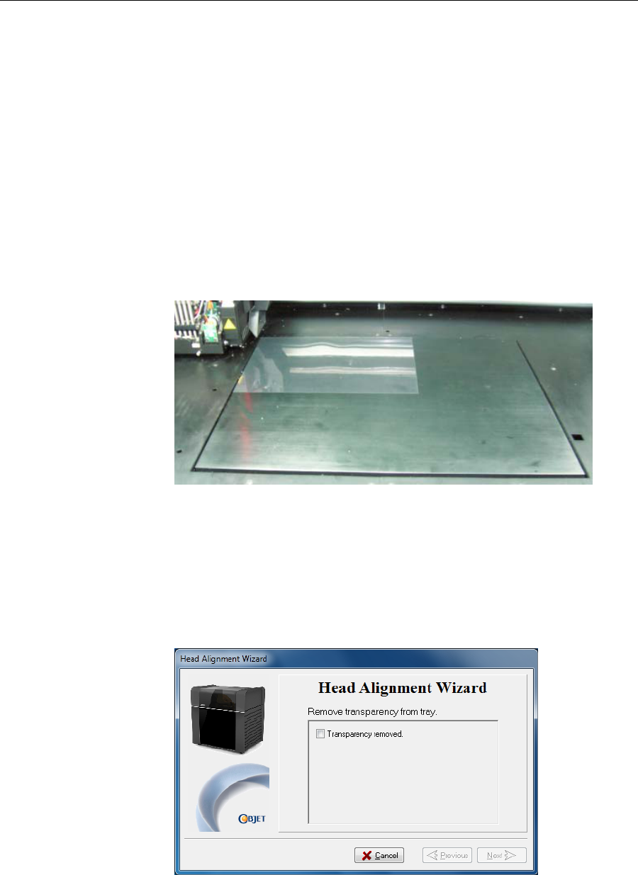
DOC-07000 Rev. A 6–31
Objet500 - Connex 3 User Guide
To check the alignment of the print heads:
1. Prepare—
•atransparencysheet—A‐4orLettersize
•anytypeofstickytape,tofastenthetransparencysheettothebuild
tray
2. StarttheHeadAlignmentWizardfromtheOptionsmenu(see
figure 6‐22onpage 6‐22).
3. ClickNexttobegin,andclosethecover.
4. Inthewizardscreen,selectthecheckboxtoconfirmthatthecoveris
closed,andclickNext.
5. Wheninstructedtodoso,placethetransparencyonthebuildtray—
nexttotheleftandrearedgesofthetray,asshowninthefollowing
figure.
Figure 6-37: Positioning the transparency on the build tray
6. Makesurethatthetransparencysheetislyingflat,andtapeittothe
tray.
7. Inthewizardscreen,selectthecheckboxtoconfirmthatthe
transparencysheetisonthebuildtray,andclickNext.
Theprinterprintstheheadalignmenttestonthetransparency.
8. Whenthefollowingscreenappears,removethetransparency.
Figure 6-38: Head Alignment Wizard—steps 8–10
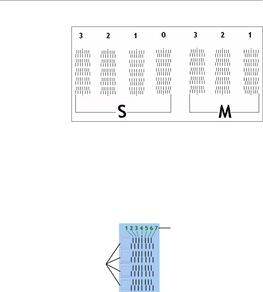
Operating & Maintaining the Objet500 - Connex 3 3D Printer
6–32
DOC-07000 Rev. A
Thetransparencysheetisprintedwithsetsofverticallinesinseven
columns,eachshowingtheresultsfromadifferentprinthead.
Figure 6-39: Sample head-alignment test
•Thethreecolumnsontherightwereprintedbytheheadsusedfor
applyingmodelmaterialwhenproducingmodels.Fromrightto
left,thecolumnsrepresentheadsM1,M2,M3,respectively.(There
isnocolumnforheadM0becauseitsalignmentisusedasa
referenceforaligningallotherheads.)
•Thefourcolumnsoflinesontheleftwereprintedbytheheadsused
forapplyingsupportmaterial.ThecolumnsrepresentheadsS3,S2,
S1andS0,respectively.
9. Foreachcolumnoflines,useamagnifyingglassorloupetoinspect
pairsofconsecutiverowsprintedonthetransparencytoseewherethe
verticallinesalign.
Figure 6-40: Comparing rows of alignment lines
Note: It does not matter which pair of lines you inspect, since they were all
printed by the same head. Choose a pair of clearly printed lines for the
inspection. (Since some nozzles may not print clearly, you may have to
inspect several pairs of lines to properly view the alignment.)
Optimumheadalignmentisshownwhenthefourthlinesintheupper
andlowerrowsarealigned,asinfigure 6‐39.Intheexampleshown,no
changetotheheadalignmentisnecessary.Ifotherlinesinthesetare
aligned,youneedtochangethealignmentofthathead—inthenext
wizardscreens.
10. Inthewizard screenshowninfigure 6‐37,selecttheTransparency
removedcheckbox,andclickNext.
Alignment-line
numbering, left-to-right
Row pairs
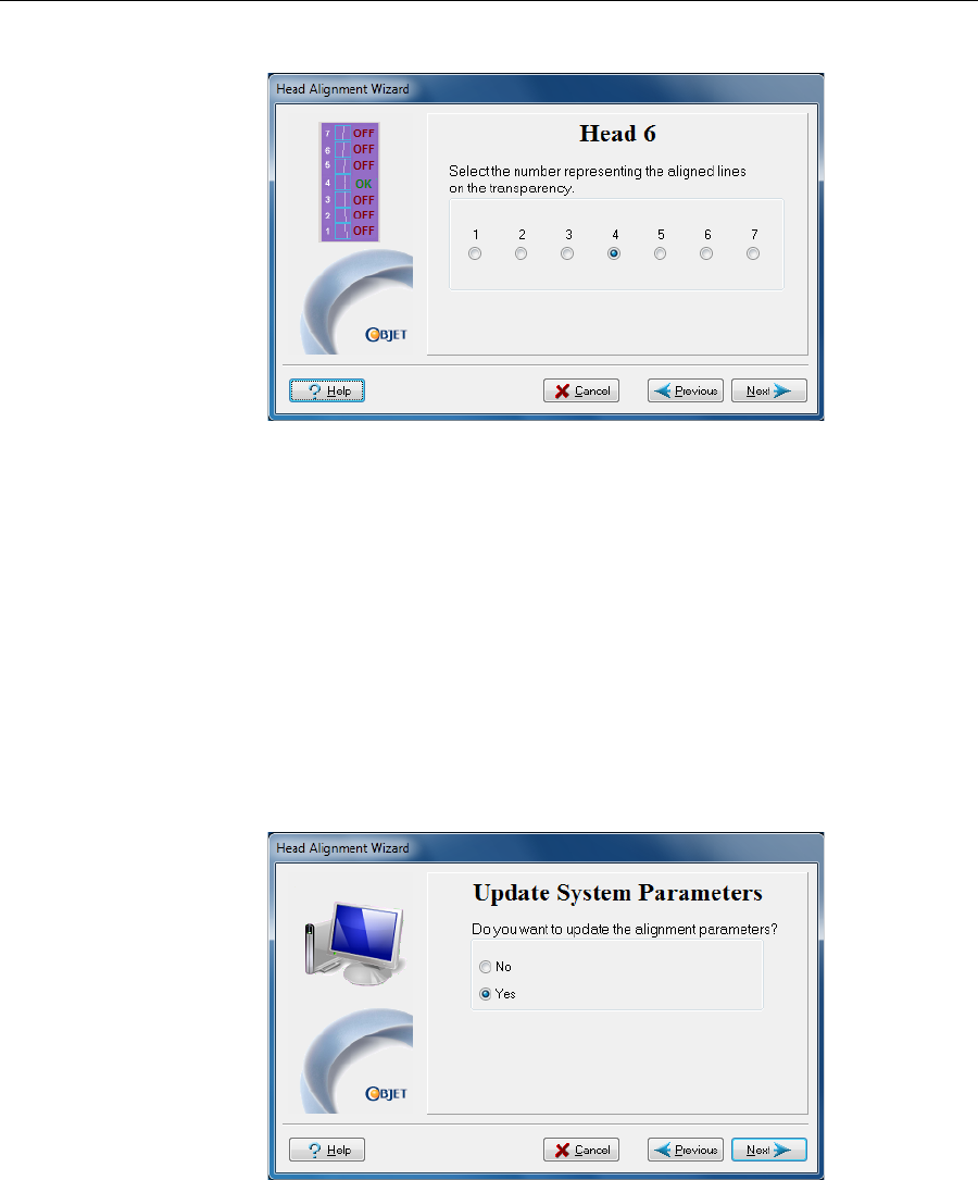
DOC-07000 Rev. A 6–33
Objet500 - Connex 3 User Guide
Thefirstinaseriesofalignmentscreensappears.
Figure 6-41: Head alignment screen
11. Inthehead‐alignmentscreen,selectthenumberthatindicateswhich
linesalignintheupperandlowerrowsofapaironthetransparency
(countingfromtheleft)forthisprinthead.
Note: Because the alignment of the fourth lines is optimum, the number “4”
is selected, by default, in the wizard screen. This does not change the head
alignment. If you select other numbers, the wizard adjusts the head
alignment, accordingly.
12. ClickNexttodisplaythenextheadalignmentscreen,andagainselect
thenumberrepresentingthemostcloselyalignedverticallinesonthe
transparencyforthatprinthead.
Whenyouhavefinishedaligningalloftheheads,thefollowingscreen
isdisplayed.
Figure 6-42: Update confirmation screen
13. Continueasfollows:
•Tomakethealignmentchangesintheprinter,makesurethatYesis
selected,andclickNext.
•Torecheckthealignmenttestresultsbeforemakingthealignment
changesintheprinter,clickPrevious.
•Ifyoudonotwanttomakealignmentchangesintheprinteratthis
time,selectNoandclickNext.
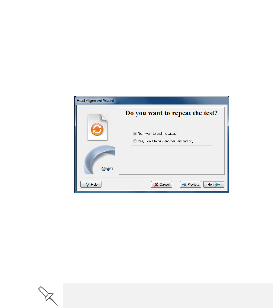
Operating & Maintaining the Objet500 - Connex 3 3D Printer
6–34
DOC-07000 Rev. A
14. Inthefinalwizardscreen,choosetoeitherrepeattheheadalignment
procedureorclosethewizard.
•Ifthemostcloselyalignedverticallinesforaprintheadwereat
eitherextreme—thefirstorseventhlines—chooseYestorunthe
HeadAlignmentWizardagain,thenclickNext.
Thetransparencytestwillshowiftheheadsarenowproperly
aligned,and—ifnot—thewizardwillallowyouto“finetune”the
alignment.
•Iftheverticallinesfortheprintheadswerenotalignedateither
extreme,chooseNotoclosethewizard,thenclickNext.
Figure 6-43: Final Head Alignment Wizard screen
Calibrating
Print Heads Theconditionoftheprintheadsdirectlyaffectsthequalityofprinted
models.Tomaintainoptimumprinting,youshouldroutinelytesttheprint
heads,andcalibratethemtothebestworkingconfigurationpossible.You
dothisbyrunningtheHeadOptimizationWizard.
If,duringtheoptimizationprocess,thewizarddeterminesthataprinthead
isfaulty—orthatitisnegativelyaffectinglayeruniformitywiththecurrent
headconfiguration—thewizardinstructsyoutoreplaceit.Ifthishappens,
youcancontinuethewizard(toreplacetheprinthead)orabortthewizard
(toreplacetheheadatanothertime).
Note: Allow at least three hours for performing this procedure (not
including time required for replacing faulty print heads).
Toaccuratelytestandcalibrateprintheads,theymustbeclean.If
necessary,runtheHeadCleaningWizardbeforebeginningthisprocedure.
To test and calibrate the print heads:
1. Prepare—
•disposablecleaninggloves
•thescalesuppliedbyObjetforuseintheWeightTest
Run the Head Optimization Wizard whenever the condition of print heads is
negatively affecting the quality of printed models, or if you suspect that there
is a problem with one or more of the print heads.
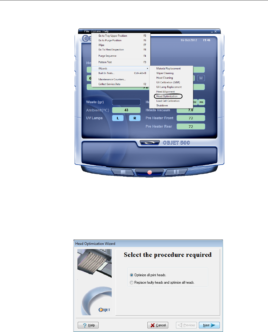
DOC-07000 Rev. A 6–35
Objet500 - Connex 3 User Guide
2. StarttheHeadOptimizationWizardfromtheOptionsmenuofthe
printerinterface.
Figure 6-44: Starting the Head Optimization Wizard
3. Intheopeningwizardscreen,clickNexttobegin.
TheWizardConditionsscreenappears.
4. Readtheconditions,selectIAgreeandclickNext.
5. Inthefollowingscreen,makesureOptimizeallprintheadsisselected,
andclickNext.
Figure 6-45: Procedure selection screen
Replacing the
Odor Filter Iftheprinterexhaustisnotconnectedtoanexternalventilationsystem,a
built‐inactivated‐carbonfilterremovesodorsfromprintingmaterials.This
filtershouldbereplacedregularly(aboutonceayear,asnecessary)tokeep
yourworkingenvironmentpleasant.Thisisnormallydoneduringthe
yearlypreventive‐maintenanceservicevisit.
Replacing the
UV Lamps TheUVlampsusedforcuringmodelshavealong,butlimited,working
life.TheObjetserviceengineertestseffectivenessduringregular
maintenancechecks,andreplacesthem,ifnecessary.Youcantestand
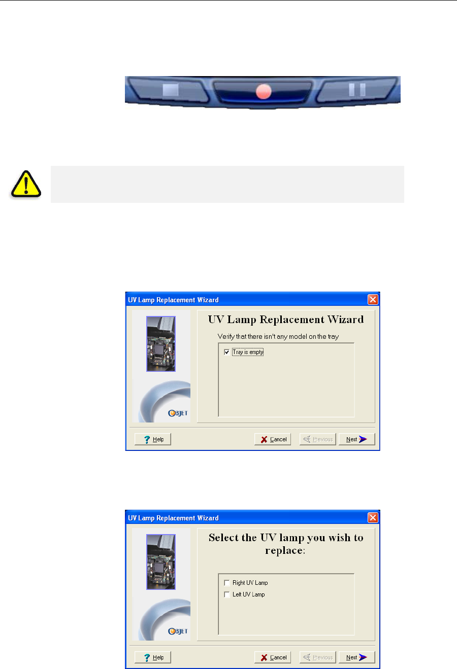
Operating & Maintaining the Objet500 - Connex 3 3D Printer
6–36
DOC-07000 Rev. A
adjusttheireffectivepowerwiththeUVCalibrationWizard(see“Testing
andCalibratingtheUVLamps”onpage 190.IfyouneedtoreplaceaUV
lamp,followtheseinstructions:
1. Makesuretheprinterisinofflinemode.
Figure 6-46: Offline mode indicator (red)
Theonline/offlinebuttonatthebottomoftheprinterinterfaceshouldbe
red.Ifnot,clickittoswitchtheprintertoofflinemode.
2. StarttheUVLampReplacementWizard.
•FromtheOptionsmenuoftheprinterinterface(seefigure 6‐33on
page 6‐27),selectWizards > UV Lamp Replacement.
3. Makesurethatthebuildtrayisempty,andconfirmthisinthewizard
screen.Then,closetheprintercoverandclickNext.
Figure 6-47: “Empty tray” confirmation screen
Theaxesmovetothe“home”position.
4. SelecttheUVlamp(s)tobereplacedandclickNext.
Figure 6-48: UV lamp selection screen
WARNING: Before continuing, make sure that the safety interlock in the
printer cover is not defeated, and that the lamp is not hot.
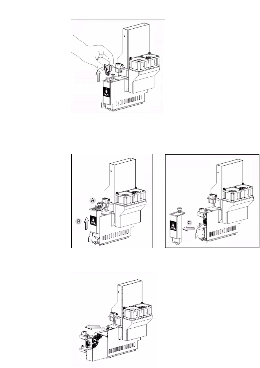
DOC-07000 Rev. A 6–37
Objet500 - Connex 3 User Guide
5. DisconnectthepowerconnectiontotheUVlamp.
Figure 6-49: Disconnecting the UV lamp
Note: Do not disconnect the power connection to the cooling fans.
6. LoosenthescrewsecuringtheUVlampcover(A),andpullthecover
up(B),thenout(C).
Figure 6-50: Removing the UV lamp cover
7. Pullthelampreflectoroutoftheprintblock.
Figure 6-51: Removing the UV lamp reflector
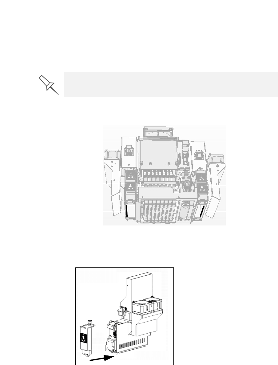
Operating & Maintaining the Objet500 - Connex 3 3D Printer
6–38
DOC-07000 Rev. A
8. Inspectthenewlampreflector,andmakesurethatablackstripis
attachedtotheinsideofit.Ifnot,installone—onthesideofthe
reflectoropposite(notnextto)theprintblock.
Note: Extra black strips are included in the printer Start-up Kit. If
necessary, you can remove the black strip from the old reflector and install
it in the new reflector (as long as the black paint has not faded).
9. Discardtheoldreflectorandlamp.
10. InsertthenewUVlamp/reflectorunitintothehousingnexttotheprint
block.
Figure 6-52: Print block and UV lamp assembly, showing correct placement of
black strip
11. Replacethelampcoverbyinsertingitintotheslotonthebottomofthe
housing,andtightenthesecuringscrewontop.
Figure 6-53: Replacing the lamp cover
Dispose of the used UV lamp in accordance with environmental and safety
requirements.
Black strip
UV lamp
assembly
Black strip
UV lamp
assembly
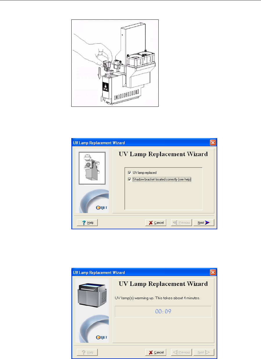
DOC-07000 Rev. A 6–39
Objet500 - Connex 3 User Guide
12. ReconnectthepowerconnectiontotheUVlamp.
Figure 6-54: Connecting power to the UV lamp
13. Inthewizardscreen,confirmthatyouhavereplacedthelamp(s)and
thattheblackstripisattached,thenclickNext.
Figure 6-55: UV-installation confirmation screen
Thewizardoperatesthelampsandchecksiftheirpoweriswithinthe
acceptablerangeforeachprintingmode.(Themodecurrentlybeing
checkedappearsinthelower‐leftcorneroftheprinterinterface.)
Figure 6-56: Status screen during UV lamp check
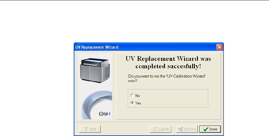
Operating & Maintaining the Objet500 - Connex 3 3D Printer
6–40
DOC-07000 Rev. A
14. AfterreplacingaUVlamp,itisrecommendedthatyoucalibrateits
powerforthevariousprintingmodes.Thefinalscreenallowsyouto
continuetotheUVCalibrationWizard(see“TestingandCalibrating
theUVLamps”onpage 6‐190).
Figure 6-57: Final wizard screen

DOC-07000 Rev. A 6–41
Objet500 - Connex 3 User Guide
Built-in Tests Thesoftwarethatrunstheprintercontainsasuiteoftestsforregularly
checkingthehardwareandsoftware,andfortroubleshooting.Youcan
configurebasiccommunicationsandenvironmentteststorun
automatically,whentheObjetsoftwareopens.Inaddition,youcanruna
morecomprehensivesetoftestsbeforeprocessingaprintjob,asasystem
check,toensureoptimumprintingresults.
Becauserunningthetestseffectstheoperationoftheprinter,youcanonly
opentheBuilt‐inTestsinterfacewhenthesystemisnotprinting.
Thetestsuitefeatures:
•Theorganizationofprinting‐relatedtasksincategories:
Communications
Datacards
Temperatures
Voltages
Encoderrepeatability
Print‐headheating
Print‐headfilling
•Acleardisplayoftestresultsandthesourceofanyfailures,enabling
youtodetermineifprintingispossibleorworthwhile.
•Theabilitytomonitortestresultsforspecificcomponents.
•Troubleshootingtips.
Runningthesetestscanhelpidentifyproblemsintheprinterhardwareand
software.Alargenumberofhardwaredefects(ornear‐defects)warnsyou
ofpossibleprintingproblems,eitherforcurrentorfuturejobs.
Objet recommends running the built-in tests in the following cases:
•as a routine test, once every two weeks
•as a system check, before major (long) jobs
•as needed, for troubleshooting
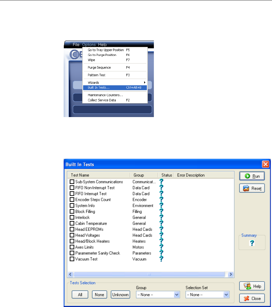
Operating & Maintaining the Objet500 - Connex 3 3D Printer
6–42
DOC-07000 Rev. A
Accessing
Built-in Tests To open the Built-in Tests screen, do one of the following:
•FromtheOptionsmenu,selectBuilt-In Tests.
•PressCtrl+Alt+B.
Figure 6-58: Selecting Built-In Tests from the Options menu
Test Interface TheBuiltInTestsscreenlistspre‐configuredtests,groupedbycomponent
categories.Inthisscreen,youselectandruntests,andtheresultsare
displayed.
Figure 6-59:Built In Tests screen
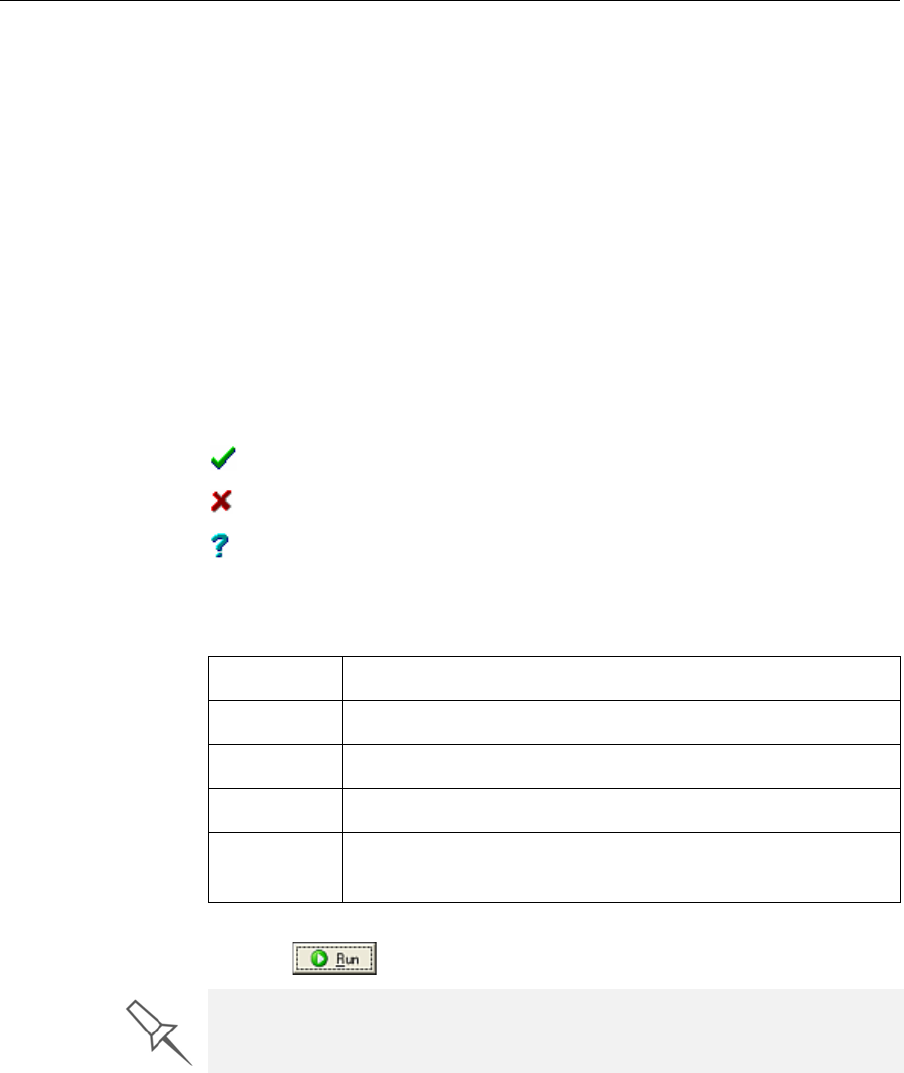
DOC-07000 Rev. A 6–43
Objet500 - Connex 3 User Guide
Test List TestName
Thiscolumnlistsallofthetests,togetherwithselectioncheckboxes.
Clickthecheckboxestoselectthetestsyouwanttorun.Toremovea
selection,clickthecheckboxagain.Toquicklyselectallofthetestsina
componentcategory,usetheGrouppull‐downmenuatthebottomofthe
screen.
Group
Thiscolumnshowsthecomponentcategoriesforeachtest.
ThistellsyouwhichtestsarerunwhenselectingacategoryfromtheGroup
pull‐downmenuatthebottomofthescreen.
Status
Thiscolumnshowsthestatusofeachtestafteryourunit:
Test Selection Area IntheTestSelectionarea,atthebottomofthescreen,youcanquicklyselect
orde‐selecttestsbytheircharacteristics:
Running Tests To run the selected tests:
¾Click.
Test Results To save and view a report of all of the tests:
¾UsetheSaveandViewcommandbuttons(seebelow).
Testsuccessfullycompleted.
Testfailed.
Unknownresults.(Thetesthasnotbeenrunyet.)
All Clicktoselectallofthetestsinthelist.
None Clicktode‐selectallofthetestsinthelist.
Unknown Clicktoselectalltestthathavenotbeenrunyet(Status = ?).
Group Usethismenutoselecttestsbycomponentcategory.
Selection
Set
Usethismenutoselectapre‐configuredsetofteststorunat
specifiedtimes(computerstartup,beforeprinting,etc.).
After you run a test, the Save and View command buttons are added to the
Built In Tests screen (see below).
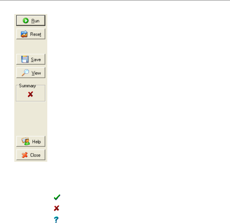
Operating & Maintaining the Objet500 - Connex 3 3D Printer
6–44
DOC-07000 Rev. A
Command Buttons Youclickthecommandbuttons,ontherightsideofthescreen,toperform
thefollowingoperations:
Run
Clicktoruntheselectedtests.
Reset
Clicktoclearpreviouslyruntests.Thisreturnsthestatusofeachtestto
Unknown(?).
Save
Clicktosaveareportthatsummarizesthetestsrun.Thereportissavedas
anHTMLfile.Youcansaveanynumberofreportsforthetestsyourun;the
nameofthefilesavedisBITReport [date][time].htm.Bydefault,thesefiles
aresavedintheObjetinstallationfolder,butyoucansaveitinanyother
folder.
View
Clicktodisplaythelatesttestreportthatyousaved.(Youcanviewother
testreportsbyopeningtherelevantfilesinyourWebbrowser.Todoso,
openWindowsExplorer,anddoubleclicktheBITReportfile.)
Close
ClicktoclosetheBuilt‐inTestsscreen.
Summary Ontherightsideofthescreen,asymbolrepresentsthecombinedresultsof
allthetestsrun,usingthesymbolsfromtheStatuscolumn.
Alltestssuccessfullycompleted.
Atleastonetestfailed.
Notalltestsperformed.

DOC-07000 Rev. A 6–45
Objet500 - Connex 3 User Guide
Test Descriptions
and
Troubleshooting
ThefollowingtableliststhenameofeachtestintheBuilt‐inTestssuite,
togetherwithitsdescriptionandapossiblereasonforitsfailure.Ifyou
needassistance,contactyourObjetserviceprovider.
Test Name Description Possible Reason for Failure
Sub‐System
Communication Testscommunicationsbetween
Edencomponents. Disconnectedcommunicationscable.
Faultycable.
FIFONon‐Interrupt/
FIFOInterrupt
TeststhedataqueueintheDATA
PCIcard. FaultyDATA_PCIcard.
Encoder Teststheencoderʹsreliabilityby
comparingreadingsfrommultiple
runsalongtheX‐axis.
Faultyencoder.
SystemInfo Comparesthefollowingparameter
valueswiththeminimum
requirements.
•Physicalmemory
•Availablememory
•Freespaceondisk
•Monitorresolution
FailureofRAMmemoryallocationin
theEdencomputer.
BlockFilling Analyzesthethermistorreadings
whentheblockisfullandwhenitis
empty.
Faultythermistor.
Interlock Teststheinterlockintheprinter
cover. Failureofinterlockmechanism.
Faultylatch.
Disconnectedcables.
CabinTemperature Teststhetemperaturelevelinthe
build‐trayarea. Faultytemperaturesensor(OHDB).
HeadEEPROM Teststheread/writecapabilitiesof
theprint‐headdrivercards. Faultyprint‐headdrivercard.
HeadVoltage Checksthecontrolofvoltages
suppliedtotheprintheads. Faultyprint‐headdrivercard.
TrayHeater Notusedforthisprinter —
Head/BlockHeaters Teststheheatersintheprintheads
andintheprint‐blockbody. Faultyheatersorthermistors.
AxesLimit Teststhehardwareandsoftware
limitsofallaxes. Faultyhardwaresensors.
WrongMaxPositionparameter.
ParameterSanity
Check Comparesthevaluesofallprinter
parameters(incfgfiles)tothe
requiredvalues.
Oneormoreoftheprinterparameters
isnotwithintherequiredrange.You
canviewdetailsintheBITreport.
Vacuum Teststhevacuumlevelintheprint
block. Faultyvacuumsensor.
Vacuumleakage.
Wrongparameters.
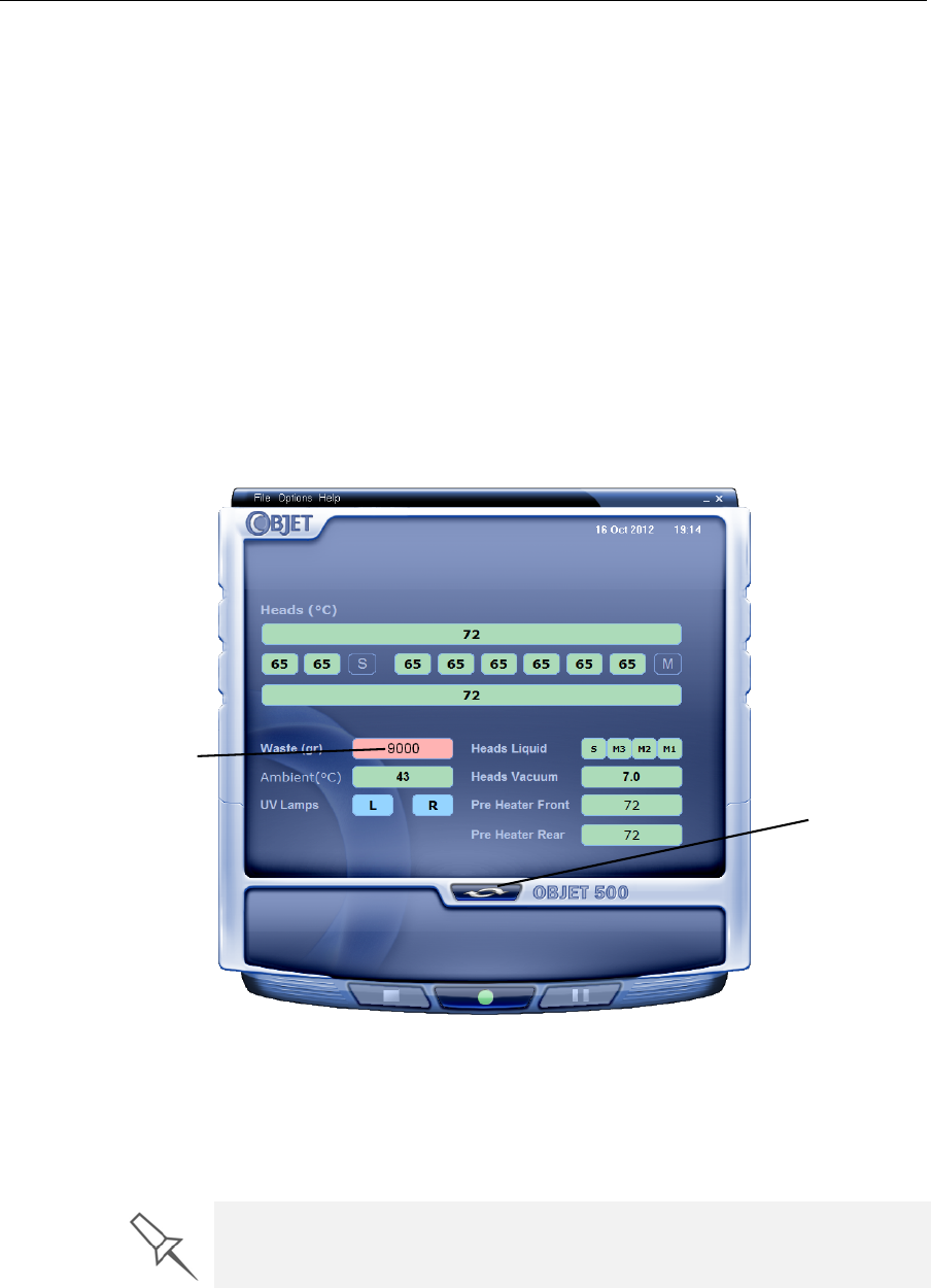
Operating & Maintaining the Objet500 - Connex 3 3D Printer
6–46
DOC-07000 Rev. A
Replacing the
Waste
Container
Thewastecontainercontainspartiallycuredpolymericmaterialproduced
duringnormaloperationandmaintenanceoftheprinter.Forsafetyand
environmentalreasons,thismaterialiskeptinaspecialleak‐proof,
disposablecontainer.
Thecontainerhasacapacityof10kilogramsofwastematerial—usually
enoughforseveralmonthsofprinteruse.Theprintersoftwaredisplaysa
warningmessagewhenthereis9kilogramsofmaterialinthecontainer,
andstopstheprintingwhenthenetweightreaches9.5kilograms.Above9
kilograms,thesoftwaredoesnotallowyoutostartaprintjob(oraprinting
activity)untilyoureplacethewastecontainer.Youcanmonitortheweight
ofthewastecontainerintheMaintenancescreenoftheprinterinterface.You
canalsovisuallyinspectthelevelofwasteinthecontainer.(Toaccessit,see
page 6‐237.)
To monitor the waste weight (and other indicators) in the printer:
¾Inthemainprinterinterfacescreen,clickthedisplaytoggletoviewthe
printerindicators.
Figure 6-60: Printer interface, showing waste weight (red background indicates
operator alert)
Thewastecontainerconsistsofaplasticcontainerinsideacardboardbox.
Youtypicallydisposeoftheentirewastecontainer—includingthebox.
Therefore,youmustassembleanewboxandinsertanewplasticcontainer
beforeyoucaninstallitintheprinter.
Waste weight
Display
toggle button
Replacement boxes, plastic containers, and sealing caps are supplied in the
Objet printer start-up kit and in the preventive-maintenance kit.
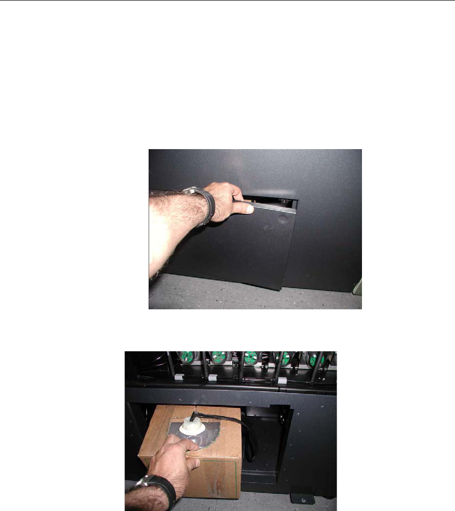
DOC-07000 Rev. A 6–47
Objet500 - Connex 3 User Guide
To prepare a new waste container:
1. Assemblethecardboardbox,makingsuretopunchouttheperforated
sections.
2. Placeanewplasticcontainerintothebox.
Note: Do not close the box until you connect the waste drain tube from the
printer (see below).
To replace the waste container:
Locatethedooronthelower‐leftsideoftheprinter.Pushintheupper‐
rightcornerofthedoortoreleasethelatchandopenthe
door.
Figure 6-61: Accessing the waste container
3. Carefullyslideoutthewastecontainertoremoveitfromtheprinter.
Figure 6-62: Removing the waste container
4. Placethenewwastecontainernexttothefullcontainer.
5. Unscrewthecapsecuringthewastedraintubeandconnectittothe
newcontainer.
6. Closethefullcontainerwithasealingcap.
7. Closethenewwaste‐containerbox,usingtapetoholditclosed.
8. Positionthewastecontainerundertheprinter,ontheloadcells.
•Thecontainershouldbeontheextremerightsideofthe
compartment.
•Makesurethatthewastedraintubeisnotcrimpedandthatitisnot
pinchedbythecontainer.

Operating & Maintaining the Objet500 - Connex 3 3D Printer
6–48
DOC-07000 Rev. A
9. Closethewastecompartmentdoor.
Cleaning the
Exterior Panels ThepaintedexteriorplasticpanelsofObjet3‐Dprintershaveadurable
finish,offeringexcellentchemicalresistancetocommoncleaningagents.
However,followtherecommendationsbelowwhencleaningtheseareasof
theprinter.
AcceptableCleaningAgents
•mildsoapsolution
•commonhouseholdcleanersandwindowcleaners
•commoncommercialandindustrialdetergents,5%solutioninwater
•alcohol(ethanol,isopropanol),10%to40%solutioninwater
Wipetheexterioroftheprinter,usingasoftclothmoistenedwiththe
cleaningsolution.
UnacceptableMaterials
•industrialsolvents
•cleaningagentscontaininghydrocarbons,ketones,estersandlacquer
thinners
•spraydisinfectants
•abrasivesandagentswhichcouldwearawaythepanelfinish
Dispose of the full waste container in accordance with environmental and
safety requirements.

DOC-07000 Rev. A 7–1
Handling Printed Models
RemovingModelsAfterPrinting.............................................................. 2
RemovingtheSupportMaterial................................................................ 2
StoringModels............................................................................................. 5

Handling Printed Models
7–2
DOC-07000 Rev. A
Removing Models After Printing
Afterprintingmodels,youshouldallowthemtocoolasmuchaspossible
beforehandlingthem.Ifadditionalmodelsdonothavetobeproducedon
theprinter,itisbesttolettheprintedmodelscoolintheprinter,withthe
coverclosed,aslongaspossible.
If the printer must be used to produce additional models as soon as
possible:
1. Lettheprintedmodelscoolonthebuildtrayforatleast10minutes.
2. Verycarefully,removethemodelsfromthetraywithascraperor
spatula(suppliedinthetoolkit),takingcarenottopryorbendthe
model.
3. Placethemodelsonaflatsurface,andcoverthemwithacardboard
boxorpaperhood.
Thisallowsthemodelstocoolslowlyandevenly.
4. Letthemodelscoolforseveralhours.
Removing the Support Material
Afterprintedmodelshavecooled,thesupportmaterialmustberemoved.
Thiscanbedonebydifferentmethods,dependingonthesizeofthemodel,
howdelicateitis,theamountandlocationofthesupportmaterial,and
otherfactors.Usethefollowingmethodsasaguide,andadaptthem(ora
combinationofthem)forfinishingthemodelsyouarehandling.
Removing Excess Support Material by Hand
Whilewearingprotectivegloves,breakawayexcesssupportmaterialon
theoutsideofthemodel.Fordelicatemodels,useatoothpick,pinorsmall
brushafterdippingthemodelinwater.
Removing Support Material with Water Pressure
Formostmodels,themostefficientwaytoremovesupportmaterialisby
usingahigh‐pressurewaterjet.OnesuitablesystemistheBalcoWaterJet
cleaningunit,showninfigure 7‐1onpage 7‐3.Thisdeviceismarketedby
Objet.
WARNING: Wear protective gloves when handling printed models
before they are washed.
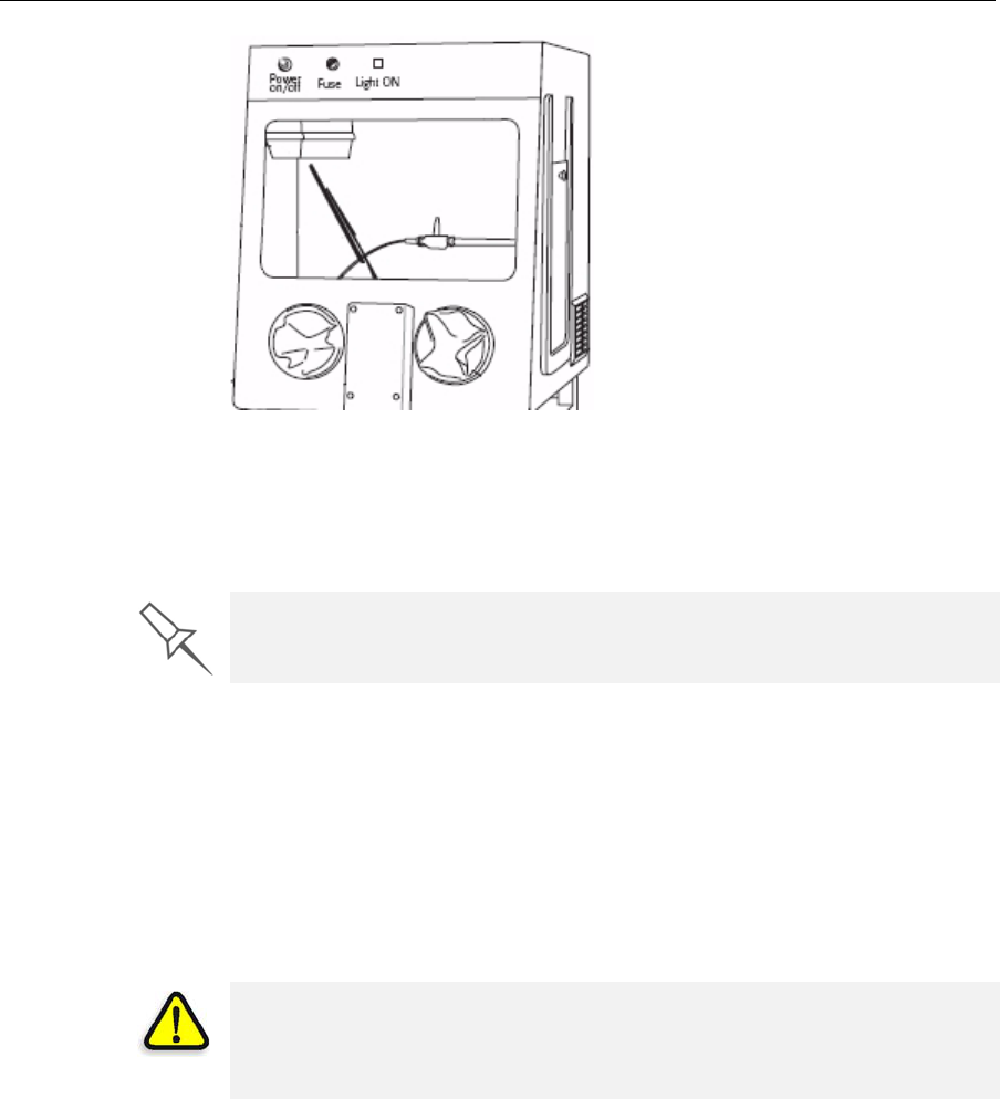
DOC-07000 Rev. A 7–3
Objet500 - Connex 3 User Guide
Figure 7-1: Balco WaterJet Cleaning Unit
Tocleanamodelusingthisdevice,youplaceitinthechamber,andyou
manipulateitandthejetusingthebuilt‐in,waterproofsleeves.Apump
turnsordinarytapwaterintoahigh‐pressurejet,andawiperkeepsthe
windowclear.
Removing Support Material with Caustic Soda
Soakmodelsina2‐percentsolutionofcausticsoda(sodiumhydroxide)to
removesupportmaterialfromdifficult‐to‐reachareasandtogivethe
modelasmooth,cleanfinish.Theamountoftimeyousoakthemodelinthe
solutiondependsonhowdelicateitisandhowmuchsupportmaterial
needstoberemoved,butitistypicallybetweenhalf‐an‐hourandseveral
hours.Inanycase,youshouldremoveasmuchsupportmaterialas
possiblebeforethecausticsodatreatment,andrinsethemodelthoroughly
(withawaterjet)afterwards.
Use caution when cleaning delicate models with high-pressure water
systems.
WARNING: Caustic soda may cause chemical burns, scarring and
blindness. Mixing it with water generates heat that could ignite other
materials.Take adequate safety precautions; always use nitrile gloves
when handling caustic soda and models soaked in it.
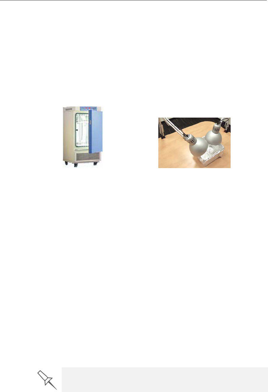
Handling Printed Models
7–4
DOC-07000 Rev. A
Post-Printing Treatment for Models Printed with Objet VeroClear
ModelsmadewithObjetVeroClearhaveaslightyellowtintwhenremoved
fromtheprinter.Thisisespeciallytrueformodelsprintedwithaglossy
finish.Theyellowtintfadesnaturallyovertime,butyoucangreatly
acceleratethisprocessbyusingasuitablephotobleachingtreatment.
Asarule,bestclarityisachievedwhenpartsareprintedwithamatte
finish,andtreatedasexplainedbelow.
Photobleachingmodelsinvolvesexposingthemtolight.Toachievehighly
controlledandpredictableresults,aprofessionalilluminationchamberis
recommended.However,adequateresultsmaybeobtainedusingordinary
desklampsfittedwithsuitablefluorescentelements.
Photo-
Bleaching
Instructions Followtheseinstructionsforphotobleachingprintedmodels.
•Thefluorescentlampsshouldberated45W,6500K.
•Whenusingdesklamps,placethemodelsinacontainercoveredwith
aluminumfoil.Useatleasttwolamps,morewhentreatingmodelsina
largecontainer.
•Arrangethemodelswithenoughspacebetweenthemtoallowlightto
reachallsidesofeachmodel.
•Verifythattheambienttemperaturearoundthemodelsis
approximately40ºC(104ºF).Highertemperaturesmaycausemodel
distortion;lowertemperaturesmaynotproducesatisfactoryresults.
Whenusingdesklamps,youcanachievetherequiredtemperatureby
positioningthelampsapproximately10cm(4in.)abovethemodels.
•Inspectthemodelsaftersixhoursoftreatment.
Forpartswithamattefinish,thisshouldbeenough.Polishand
lacquertheparts.
Forpartswithaglossyfinish,continuethephotobleaching
treatmentforupto18hoursmore.
InObjetlaboratories,therewasatintreductionofapproximately70%
withinsixhours.After24hours,tintwasreducedbyapproximately
90%.
Figure 7-2: Figure 7-3:
For more information about this treatment, see the application note
“Objet VeroClear for Desktop Pro Printers” (DOC-24131).

DOC-07000 Rev. A 7–5
Objet500 - Connex 3 User Guide
Storing Models
Modelsarecuredastheyareprinted,makingthemsafeandstablefora
longtime.However,properstorageconditionsarenecessarytoprevent
deforming.
•Keepprintedmodelsatroomtemperatureandinalow‐humidity
environment.
•Donotexposemodelstodirectsunlightandotherheatsources.

Handling Printed Models
7–6
DOC-07000 Rev. A