Stratasys RFID Assembly of RFID reader and two antenna boards User Manual Connex500 350 User Guide
Stratasys Ltd Assembly of RFID reader and two antenna boards Connex500 350 User Guide
User Manual

DOC-13000 Rev. E 7–1
Operating & Maintaining the
Connex500/350 3-D Printer
StartingtheConnexPrinter ............................................................... 2
LoadingModelandSupportCartridges.......................................... 4
ProducingModels ............................................................................... 5
PrinterInterfaceColor Key.................................................................. 7
PrintingIndicators ................................................................................ 8
ResumingProductionAfterPrintinghasStopped......................... 9
ChangingtheModelMaterial ......................................................... 10
KeepingtheConnexPrinterinIdleMode..................................... 15
ShuttingDowntheConnexPrinter ................................................ 16
MaintainingtheConnexPrinter ..................................................... 18
RoutineMaintenanceSchedule......................................................... 18
CleaningthePrintHeads................................................................... 19
PatternTest........................................................................................... 21
ImprovingPrintQuality .................................................................... 22
CleaningandReplacingtheWiper................................................... 23
ReplacingtheRollerScraper(Knife) ................................................ 28
AligningthePrintHeads ................................................................... 30
CalibratingPrintHeads ..................................................................... 34
ReplacingPrint Heads........................................................................ 40
TestingandCalibratingtheUVLamps ........................................... 49
CalibratingtheLoadCells ................................................................. 51
ReplacingtheOdorFilter................................................................... 52
ReplacingtheUVLamps ................................................................... 52
Built‐inTests......................................................................................... 57
ReplacingtheWasteContainer ......................................................... 62
CleaningtheExteriorPanels ............................................................. 64
Operating & Maintaining the Connex500/350 3-D Printer
7–2
DOC-13000 Rev. E
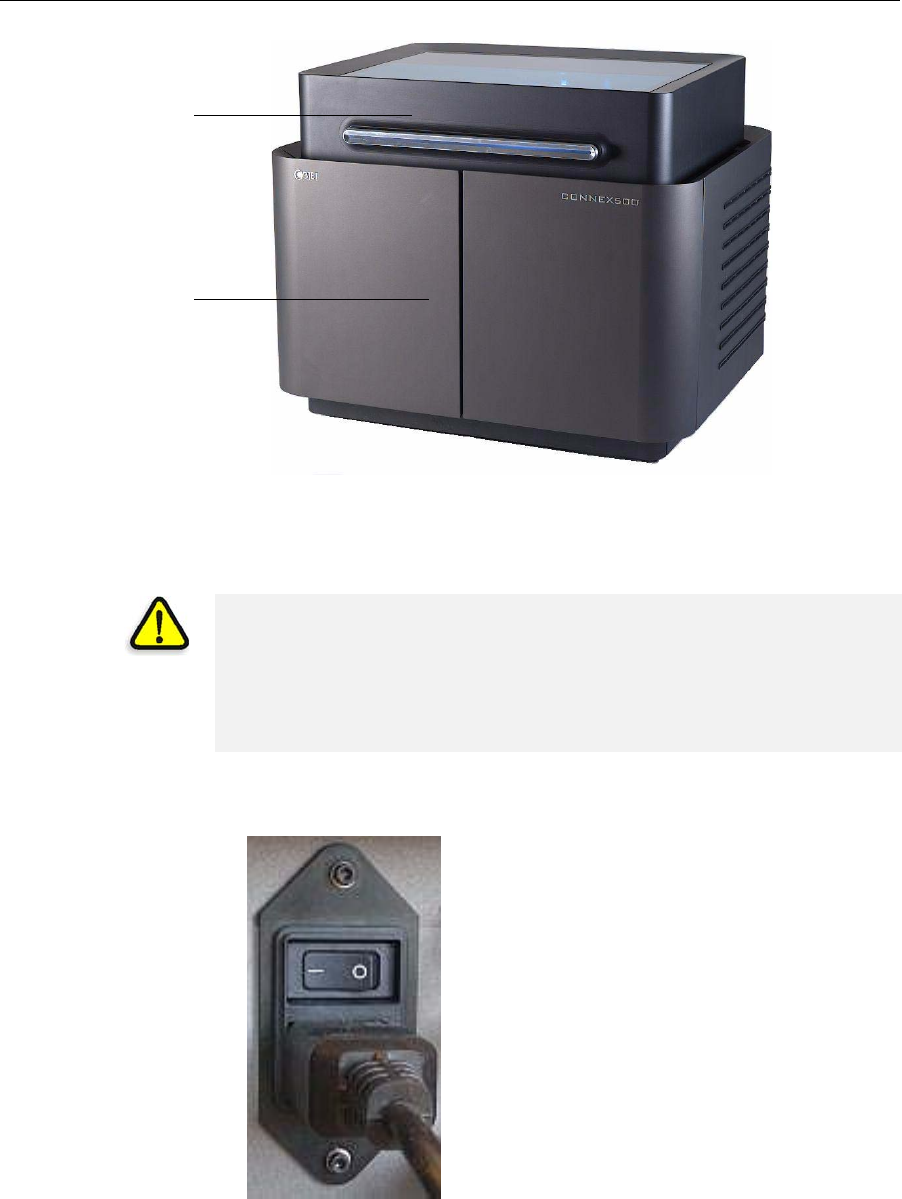
Figure 7-1: The Connex500 3-D Printer
Starting the Connex Printer
1. Turnonthemainpowerswitch,locatedatthebackoftheConnex
printer.
Figure 7-2: Main power cable and switch
ThemainpowerswitchturnsontheConnexprinter,whichincludes
thebuilt‐inConnexcomputer.
Printer cover
Printing-materials &
storage compartment
CAUTION!
•Do not attempt to operate the Connex printer before being trained by
an Objet customer-support representative.
•Observe all safety warnings and follow the safety guidelines described
in chapter 2.
DOC-13000 Rev. E 7–3
Connex500/350 User Guide
2. Afterthecomputerboots,logintoWindowsandlaunchtheConnex
controlapplication:
•Onthecomputerdesktop,double‐clicktheConnexprintericon.
or—
•FromtheStartmenu,selectObjet > Connex500/350Connex500/350.
TheConnexprinterinterfacescreenopens(seefigure 7‐3).Allmonitoring
andcontrollingoftheConnexprinterisdonefromthisinterface.
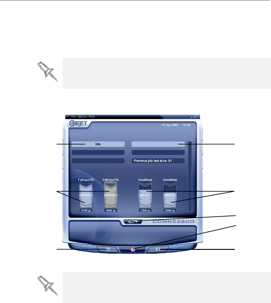
Figure 7-3: Connex500 interface
A valid HASP key is required on the printer computer for the application to
open. This key should be installed during printer installation. If the
application does not open and a HASP message appears, contact your
dealer or Objet Customer Support.
Printer mode Current activity
Support material
cartridges
Display
toggle button
Pause button
Stop button
Online/offline
button
Model material
cartridges
Connex installations utilize one monitor for displaying both the computer
running Objet Studio / Job Manager and the computer installed inside the
printer. Make sure that the KVM (keyboard-video-mouse) switch is in the
correct position so that the Connex printer interface is displayed.

Operating & Maintaining the Connex500/350 3-D Printer
7–4
DOC-13000 Rev. E
Loading Model and Support Cartridges
Connexprintersusetwocartridgesofmodelmaterialandtwocartridgesof
supportmaterial,eachweighing3.6kilogramswhenfull.Agraphical
representationofthecartridgesandtheircurrentweightappearsinthe
printerinterface(seefigure 7‐3).
——
Important:Ifyouneedtoreplacethemodelmaterialcurrently
installedwithanothertype,see“ChangingtheModelMaterial”
onpage 7‐10.Otherwise,makesuretoreplacethemodel
cartridgewithonecontainingthesametypeofmaterial.
To load model and support cartridges:
1. OnthefrontoftheConnexprinter(seefigure 7‐1),pullopenthedoors
ofthestoragecompartment.
2. Ifyouarereplacingacartridge,graspitshandleandpullthecartridge
out,takingcarenottotwistorturnit.
3. Loadmodelandsupportcartridgesintotheirrespective
compartments—themodelcartridgeontheright,andthesupport
cartridgeontheleft.(Notethatthecartridgesonlyfitintotheircorrect
compartments.)
Youshouldfeelsomeresistance,asaneedlepiercesthecartridge.
4. ChecktheConnexprinterinterfacetomakesurethatthenewcartridge
isdetectedandthatitsweightisdisplayed(seefigure 7‐3).
5. Closethestorage‐compartmentdoor.
The printer uses RFID technology to automatically identify the material
cartridges. For this purpose, an RFID module is part of the printer hardware.
Tampering with this module will render the printer inoperable and may void
Objet warranties and service contracts.
Tips about replacing cartridges:
•You can replace material cartridges either before or during printing.
•You can replace partially used cartridges to avoid the need for replacing
them during printing.
•You can load partially used cartridges, as long as they contain more
than 100 grams of material.
DOC-13000 Rev. E 7–5
Connex500/350 User Guide
Producing Models
TheConnex500/350printerproducesmodelsbyprintingtrayfiles
preparedintheObjetStudioapplicationandsenttotheprinterfromthere.
Forinformationaboutpreparingmodelfilesforprinting,see”UsingObjet
Studio”orObjetStudioHelp.
To prepare the Connex printer for producing models:
1. MakesurethatthebuildtrayintheConnexprinterisemptyandclean.
Ifnot,removeoldmaterialwiththescraper,andcleanthetray
thoroughlywithcleaningfluid.
2. Makesurethatthereissufficientmodelandsupportmaterialloaded
intheprinter,asindicatedintheConnexprinterinterface(see
figure 7‐3).Youmaywanttoreplacethecartridgesofmodeland
supportmaterialcurrentlyloadedintheprintertoavoidtheneedfor
replacingthemduringprinting.
3. AtthebottomoftheConnexprinterinterface,clicktheredbuttonto
switchtheprintertoonlinemode.
Thecolorofthebuttonchangesfromredtogreen(seefigure 7‐4).If
thereisajobintheJobManagerqueue,itissenttotheprinter.
OntheConnexprinterinterface,theprintermodechangesfromIdletoPre‐
print,astheprinter’scomponentspreparethemselvesforproduction:
•Theprintblockisheated.
•TheUVlampsarepoweredandtheywarmup.
Whenprintingbegins,JobManagersendssevenslicestotheConnex
printer.ThisisthestandardbufferbetweentheJobManagerandthe
printer.Aseachsliceisprinted,theJobManagersendsanotherslicetothe
printer.
Dependingonthesizeofthemodel(s)tobeproduced,printingcantake
betweenseveralhourstoseveraldays.Aslongasthereisenoughmodel
andsupportmaterialinthesupplycartridges,printingproceeds
automaticallyuntilthejobisfinished.
Before beginning to produce models, it is recommended that you check the
current printing quality of the print heads by performing a pattern test (see
“Pattern Test” on page 21).
CAUTION: Use protective gloves when cleaning the build tray, and be
careful of the sharp edges of the scraper blade.
Forinstallingmaterialcartridgesandreplacingemptyones,see
“LoadingModelandSupportCartridges”onpage 7‐4.
Forchangingthetypeofmodelmaterialcurrentlyloaded,see
“ChangingtheModelMaterial”onpage 10.
During printing, the server computer must remain on and it must
communicate with the Connex printer. Do not log-off Windows until printing
is finished.
Operating & Maintaining the Connex500/350 3-D Printer
7–6
DOC-13000 Rev. E
TheConnex500/350printerusesoneortwomodel‐materialcartridgesand
onesupport‐materialcartridgetoproducemodels.Ifadditionalcartridges
areinstalledandtheyarenotneededforthecurrentprintjob,theprinter
interfaceindicateswhicharebeingused:
•Bluecartridge—usedfortheprintjob
•Graycartridge—notusedfortheprintjob
Youcanmonitorprinterstatusindicatorsbyswitchingtheprinterinterface
display.Todothis,clickthedisplaytogglebuttonintheprinterinterface
screen.
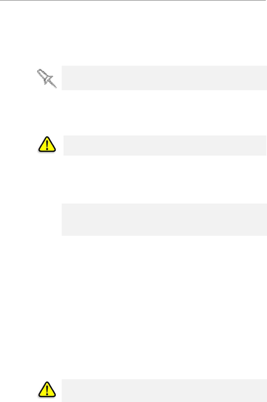
Figure 7-4: Connex printer indicators
Block temp.
in front of
support heads
Block temp.
behind
support heads
Waste weight
Display
toggle button
Printer set to
online mode
(green)
Temp. of each
support head
Chamber temp.
Left UV lamp
Right UV lamp
Block temp.
behind model
heads
Temp. of each
model head
Block temp. in
front of model
heads
Support/Model
material in print-
block reservoir
System
vacuum level
Pre-heating of
support & model
material

DOC-13000 Rev. E 7–7
Connex500/350 User Guide
Printer
Interface
Color Key
Thebackgroundcolorsintheprinterindicatorfieldstellyouataglance
whetherornotthevalueoritemissuitableorreadyforprinting.
•Green—suitable/readyforprinting
Forexample,infigure 7‐4:
Ambient—Theambienttemperatureoftheprintingchamberis
withintheacceptablerange.
HeadsLiquid—Thelevelofmodelandsupportmaterialintheprint‐
blockreservoirisOK.
HeadsVacuum—Thevacuumlevelinthesystemiswithinthe
acceptablerange.
•Red—notsuitableforprinting(orindicatesawarning)
Forexample,infigure 7‐4:
Waste—Theweightofthewastecontainerisgrams,morethan
allowedwhenbeginningaprintjob.(See“ReplacingtheWaste
Container”onpage 7‐62.)
•Blue—notready
Forexample,infigure 7‐4:
UVlamps—TheUVnoton.
Heads(°C)—Theheadshavenotreachedthetemperaturerequired
forprintingmodels(inprintingmode).
Thecolorofthematerialcartridgesdisplayedintheprinterinterface
indicateswhichcartridgesareactiveforthecurrent(ornext)printjob.
•Blue—activecartridges
•Gray—reservecartridges
Operating & Maintaining the Connex500/350 3-D Printer
7–8
DOC-13000 Rev. E
Printing
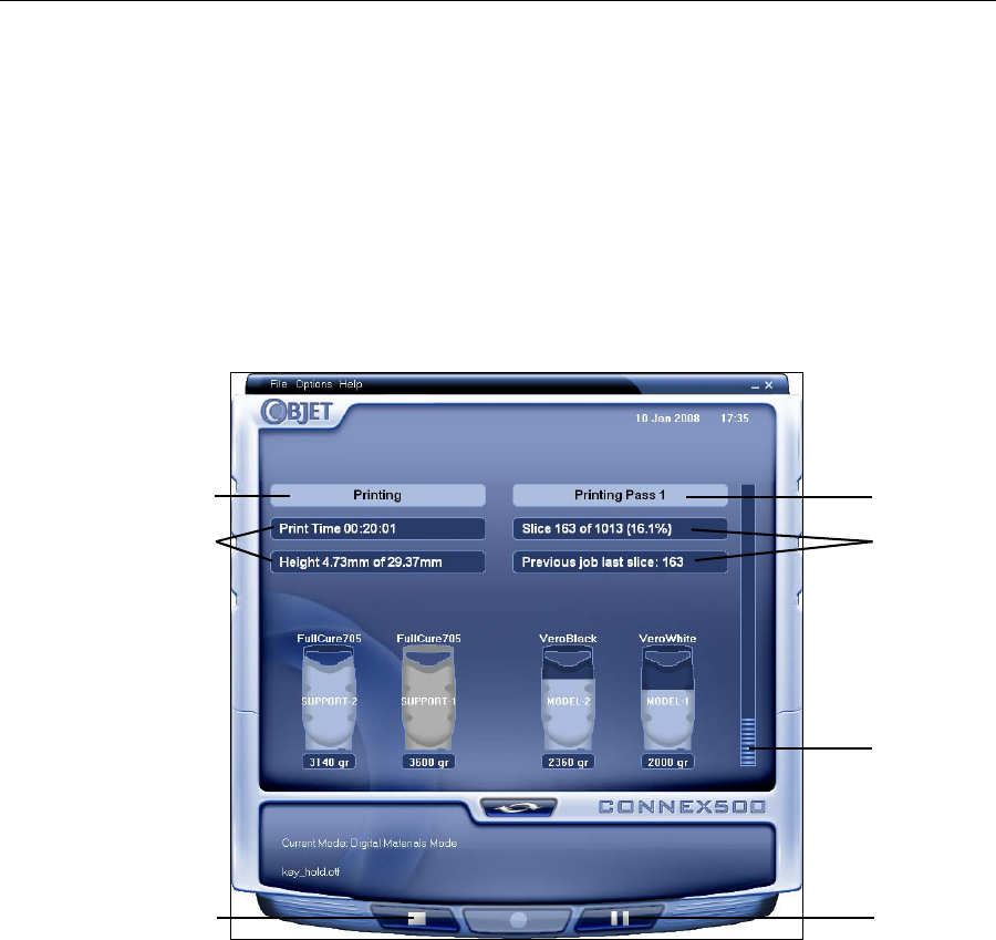
Indicators TheprinterinterfacescreenchangeswhenyousendaprintjobfromJob
Managertotheprinter,andtheprinterisonline(seefigure 7‐5):
•ThemodechangesfromPre‐printtoPrinting.
•Thespecificactivitybeingperformedisshowninthe“currentactivity”
field.
•Currentjob‐printinginformationisdisplayed.
•Theprintingprogressbarisdisplayed.
•TheStopandPausebuttonsareenabled.
Whentheweightofacartridgedropsbelow100grams,thedisplayofthe
materiallevelintheprinterinterfaceisred.
Figure 7-5: Connex printer interface during printing
Current Activity
Job information
Progress bar
Pause button
Stop button
Printer mode
Job information
DOC-13000 Rev. E 7–9
Connex500/350 User Guide
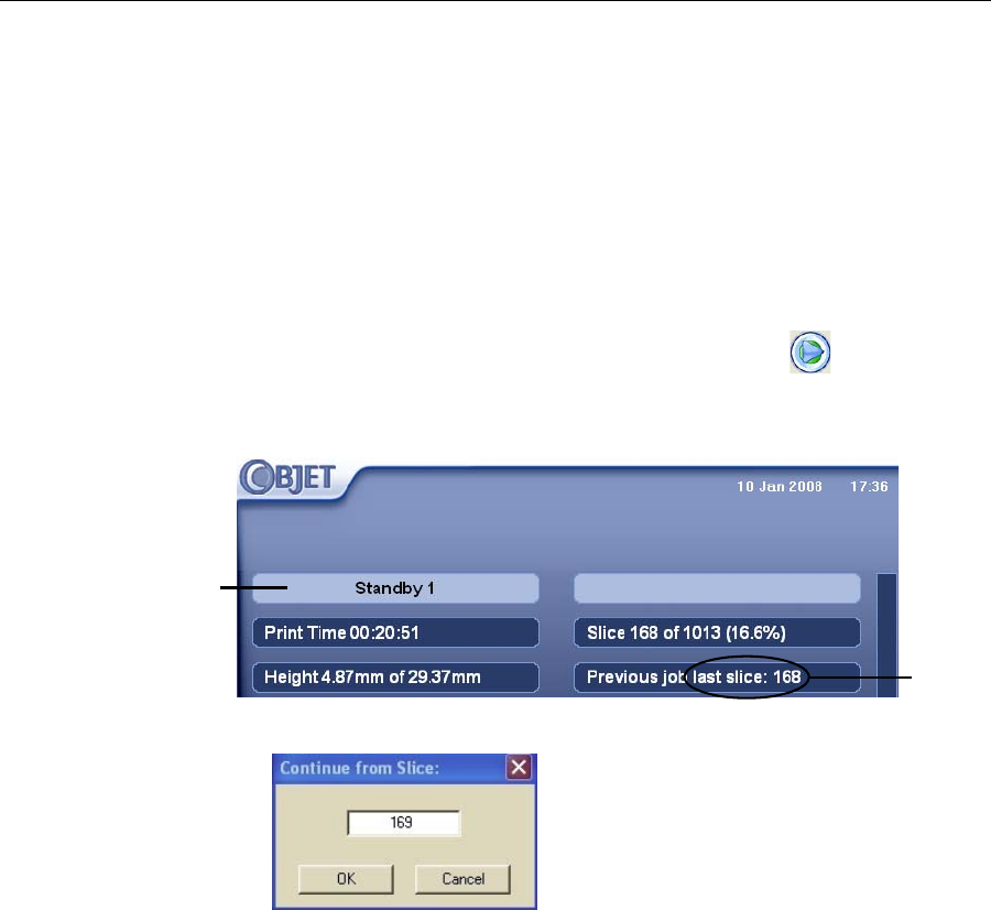
Resuming Production After Printing has Stopped
Iftheprintingprocessisinterruptedforanyreason,JobManagerstops
sendingslicestotheConnexprinter.
To continue printing the model:
1. Switchtheprintertoonlinemodebyclickingtheredbuttonatthe
bottomoftheConnexprinterinterface(seefigure 7‐3onpage 3).
Thebuttonchangesfromredtogreen(seefigure 7‐4onpage 6).
2. MakesurethatthecomputernetworkconnectingtheprinterandJob
Managerserverisactive.
3. IntheJobManagerinterface,clicktheResumeicon.
4. IntheContinuefromSlicedialogboxthatappears,confirmtheslice
number,aftercheckingtheConnexprinterinterface.
Figure 7-6: Connex printer interface after interrupted printing
Figure 7-7: Continue from Slice confirmation dialog box in server
(Job Manager) interface
5. If,foranyreason,thecorrectnumberdoesnotappearinthedialog
box,enterthenumberandclickOK.
Youcannotcontinueprintingthemodelif:
•ThenumberofthelastsliceprinteddoesnotappearintheConnex
printerinterface,eveniftheservercomputerdisplaystheContinuefrom
Sliceconfirmationdialogbox.
•Therewasarelativelylonginterruptioninprinting,evenifthe“last
slice”and“continuefromslice”indicatorsarecorrect.Thepartofthe
modelalreadyprintedmaydeformorshrink,andtheremightbea
visibledifferencebetweenitandthenewlyprintedpart.Theeffectsofa
printingstoppageonamodeldependonthemodelsizeandstructure,
modelmaterialused,ambienttemperatureandthelengthofthe
stoppage.
Printer mode
Last slice
printed
Operating & Maintaining the Connex500/350 3-D Printer
7–10
DOC-13000 Rev. E
If you cannot continue printing:
1. CanceltheprintjobinJobManager.
2. Removethepartiallyprintedmodelfromthebuildtray.
3. SendthejobtotheConnexprinteragain.
Changing the Model Material
Beforeproducingmodelsusingadifferenttypeofmodelmaterialthanis
currentlyinstalled,runtheMaterialReplacementwizardtoflushtheprint
blockandfeedtubes.
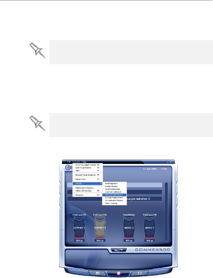
To replace the model material:
1. StarttheMaterialReplacementwizardfromtheOptionsmenu.
Figure 7-8: Starting the Material Replacement wizard from the Options menu
2. Intheopeningscreen,clickNext.
3. Iftheprintercoverisnotclosed,ascreenappearsinstructingyouto
closethecover.ConfirmthatitisclosedandclickNext.
You can stop and later resume printing from either the Connex printer
interface or the Job Manager interface, since both applications are updated
when you use these commands. However, after clicking the Pause button in
the printer interface, you can only resume printing from the printer interface.
You should carefully plan printing models with different model materials to
avoid unnecessary waste of the material loaded in the printer. The amount
of material flushed depends on the flushing cycle chosen and if you are
replacing one or both cartridges.
DOC-13000 Rev. E 7–11
Connex500/350 User Guide
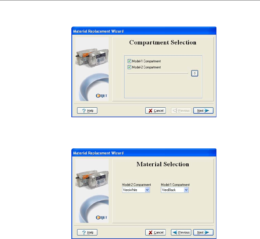
4. IntheCompartmentSelectionscreen,selectthecartridge(s)youwantto
replace,andclickNext.
Figure 7-9: Compartment Selection screen
5. Fromthedrop‐downmenu,choosethemodelmaterialyouwantto
install,andclickNext.
Figure 7-10: Material Selection screen
Note: This selection automatically affects the default material settings in
Objet Studio.
6. TheMaterialReplacementWizardcontinuesasfollows:
•If,accordingtoyourselectionsinthepreviouswizardscreens,you
arereplacingbothmodelmaterialcartridges,andtheprinterwillbe
loadedwithtwocartridgescontainingthesamemodelmaterial,the
Connexprinterflushestheentiresystem,andpreparesforprinting
inSingle‐Materialmode(seebelow).Continuewithstep8on
page 7‐13.
•If,accordingtoyourselectionsinthepreviouswizardscreens,you
arereplacingbothmodelmaterialcartridges,andtheprinterwillbe
loadedwithtwodifferentmodelmaterials,theConnexprinter
flushestheentiresystem,andpreparesforprintinginDigital‐
Materialmode(seebelow).Continuewithstep8onpage 7‐13.
•If,accordingtoyourselectionsinthepreviouswizardscreens,you
arereplacingonlyoneofthemodel‐materialcartridges,andthe
Operating & Maintaining the Connex500/350 3-D Printer
7–12
DOC-13000 Rev. E
printerwillbeloadedwithcartridgescontainingtwodifferent
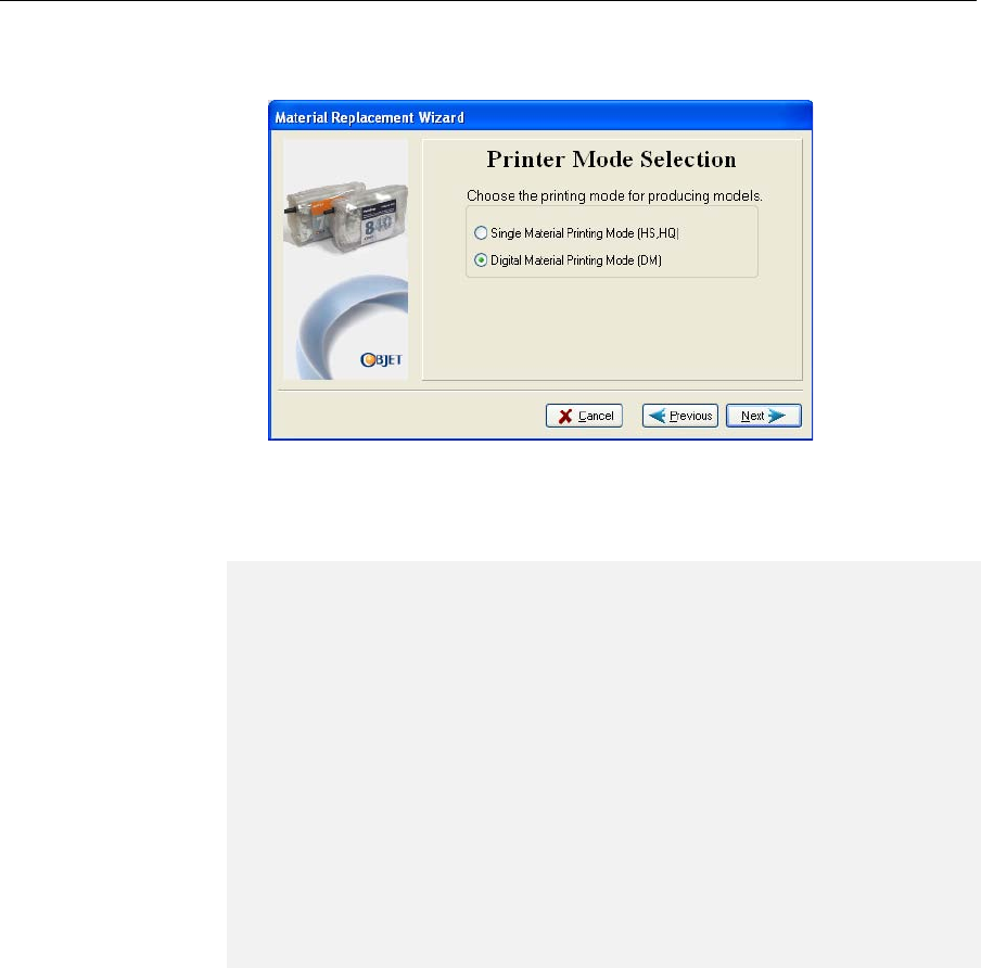
modelmaterials,thePrinterModeSelectionscreenappears.
Figure 7-11: Printer-mode selection
7. ChoosewhetheryouwanttoproducemodelsinSingle‐Materialmode
orinDigital‐Materialmode,andclickNext.
Continuewithstep8onpage 13.
•Single Material mode
Allfourprintheadsareusedtoprint,usingonemodelmaterial.
ThismodeisrequiredtoproducebuildtrayswiththeHighQuality
setting,andtoproducetrayswiththeHighSpeedsettingusingonly
onemodelmaterial.
•Digital Material mode
Eachofthemodelmaterialsloadedisusedintwoofthefourprintheads.
Ifonlyoneofthemodelmaterialsisrequiredforprinting,models
areproducedusingtwoprintheads.Thismakesitunnecessaryto
replacetheothermodelmaterialcartridge.
Ifmodel‐materialsubstitutionisallowed,theprinterproducestrays
withtheHighSpeedsettingusingamixtureofbothmodelmaterials
(see“ModelMaterialSubstitution”onpage 5‐37).
DOC-13000 Rev. E 7–13
Connex500/350 User Guide
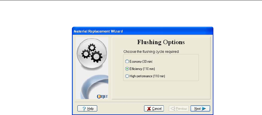
8. IntheFlushingOptionsscreen(seefigure 7‐12),choosehowthoroughly
youwanttoflushthesystem.
Figure 7-12: Flushing Options screen
•Economy.Thiscyclecanbeusedwhenreplacingalight‐colored
modelmaterialwithadarkermaterial(suchasTangoBlack™or
VeroBlack™),oriftheexactcoloroftheprintedmodelsis
unimportant.
Thewizardflushesthesystemwiththeminimumamountof
materialneededtoensurethatmodelshavethemechanical
propertiesofthenewmaterial.
•Efficiency.Thisoptionisadequate,inalmostallsituations,for
printingmodelswithuniformandaccuratecolor.Itis
recommendedbecauseitcanpotentiallysave25to75percentofthe
materialusedtoflushouttheoldmaterial,comparedtotheHigh
Performancecycle.Note,however,thattheremaybetimeswhenthe
shade(color)oftheprintedmodelisslightlyaffectedbymaterial
previouslyused.
Thewizardidentifiesthefeedtubesandprintheadsrequiring
cleaning,basedonyourselectionsinthepreviousscreens,and
flushesonlythesepartsofthesystem.
•HighPerformance.Usethiscyclewhentheprintedmodelsmust
havetheexactcolorofthenewmaterial.
Thewizardthoroughlyflushesallofthefeedtubesandprintheads
neededforprinting,basedonyourselectionsintheprevious
screens.Thisisdoneevenifaselectedmaterialisalreadypresentin
thesystem,sinceitmightcontainsmallamountsofmaterial
previouslyused.
Operating & Maintaining the Connex500/350 3-D Printer
7–14
DOC-13000 Rev. E
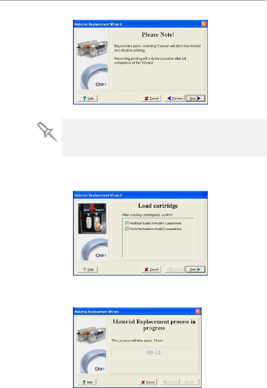
9. ClickNext,andtakenoteofthewarningscreen.
Figure 7-13: Material Replacement warning screen
10. Tocontinue,clickNext.
11. Whenprompted,loadthenewcartridge(s).Confirmthisinthewizard
screenandclickNext.
Figure 7-14: Prompt to load new model cartridges
Afteridentifyingthenewcartridge(s),theConnexprinterbeginsfilling
theprintheadswiththenewmodelmaterial.
Figure 7-15: Material replacement: filling heads with new material
Once you start this procedure, you must complete it before you can produce
models with the Connex printer. To perform the procedure at another time,
click Cancel. If you continue (by clicking Next) and you do not complete the
procedure, you must start the Material Replacement wizard again before
producing models.
DOC-13000 Rev. E 7–15
Connex500/350 User Guide
12. Whenthefinalwizardscreenappears,makesurethatthescreen
displaysthenewly‐loadedmaterial(s).ClickDonetoclosethewizard.
Theprinter‐controlinterfaceisautomaticallyupdated,andshould
displaythenewmaterials.TheObjetStudiointerface(ontheprinter‐
serverworkstation)isalsoupdated,anddisplaysthenewmaterials.
Keeping the Connex Printer in Idle Mode
Betweenprintingjobs,theConnex500/350printercanbekeptonforupto
oneweek.Iftheprinterwillnotbeusedformorethanaweek,usethe
shutdownwizardtoautomaticallyperformtheproceduresthatmustbe
donebeforeturningofftheprinter(see“ShuttingDowntheConnex
Printer,”below).
WhentheConnex500/350printerstopsproducingmodels,theprinter
softwareautomaticallyreducesthetemperatureoftheprintheadsas
follows:
Note: The printer mode is indicated in the green field on the left of the
interface (see figures 7-3, 7-4 and 7-5 on pages 3, 6 and 8).
If,afterprintingajob,youknowthattheprinterwillnotbeusedfor10
hoursormore,youcanimmediatelyturnofftheheatingoftheprintheads
byputtingtheprinterintoIdlemode.
To put the printer into Idle mode:
¾FromtheFilemenu(intheprinterinterface)clickExit.
Note: The printer remains in Idle mode until you open the Connex printer
application and begin printing again.
CAUTION: Dispose of all material cartridges in accordance with all
applicable laws and regulations. If necessary, the cartridges can be
disassembled for recycling. If this is done, protect the person handling
the cartridges from direct exposure to uncured resins.
Time after printing Mode Change in heating of print heads
first15minutes Standby1none
next10hours Standby2heatingreduced(toroomtemp.)
after10hours Idle heatingstopped
When the printer is in Idle mode, do not turn it off. It can remain in this
mode—with the cover closed—for up to a week. For longer periods, shut
down the printer by running the Shutdown wizard (see below).
Operating & Maintaining the Connex500/350 3-D Printer
7–16
DOC-13000 Rev. E
Shutting Down the Connex Printer
YouonlyneedtoshutdowntheConnexprinterifitwillnotbeusedfora
weekormore.Otherwise,theprintercanremainon,inIdlemode.To
properlyshutdown,theprinterneedstoperformseveralprocesses.These
arecontrolledbytheShutdownwizard.Donotattempttoshutdownthe
printerbysimplyclosingthecomputerinterface(theprinter‐control
application),andneverdisconnectpowertotheprinterbefore
completingthiswizard.
Dependingonthelengthoftimetheprinterwillnotbeused,youcan
choosebetweenashortshutdownprocedure,andamorethorough
procedure.
•Upto10days:Thewizardemptiestheprintblockofmodeland
supportmaterial,topreventleaks.Thistakesabout10minutes.
•Morethan10days:Thewizardemptiestheprintblock,thenflushes
thesystemwithcleaningfluid.Thistakesupto35minutes,andyou
mustbepresenttoloadcleaning‐fluidcartridgeswheninstructed.
To run the Connex Shutdown Wizard:
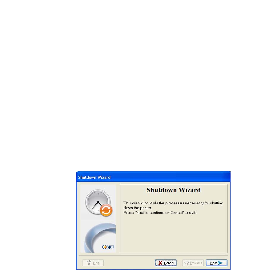
1. SelectShutdown fromtheOptionsmenu,orpressF8.
Figure 7-16: Shutdown wizard, opening dialog box
2. Intheopeningwizardscreen,clickNext.
3. Choosetheappropriateoptionforthelengthoftimethattheprinter
willnotbeused—lessormorethantendays.
Note: Before selecting More than 10 days, make sure that cleaning-fluid
cartridges are available.
4. Inthenextscreen,verifythatthetrayisemptyandclickNext.
DOC-13000 Rev. E 7–17
Connex500/350 User Guide
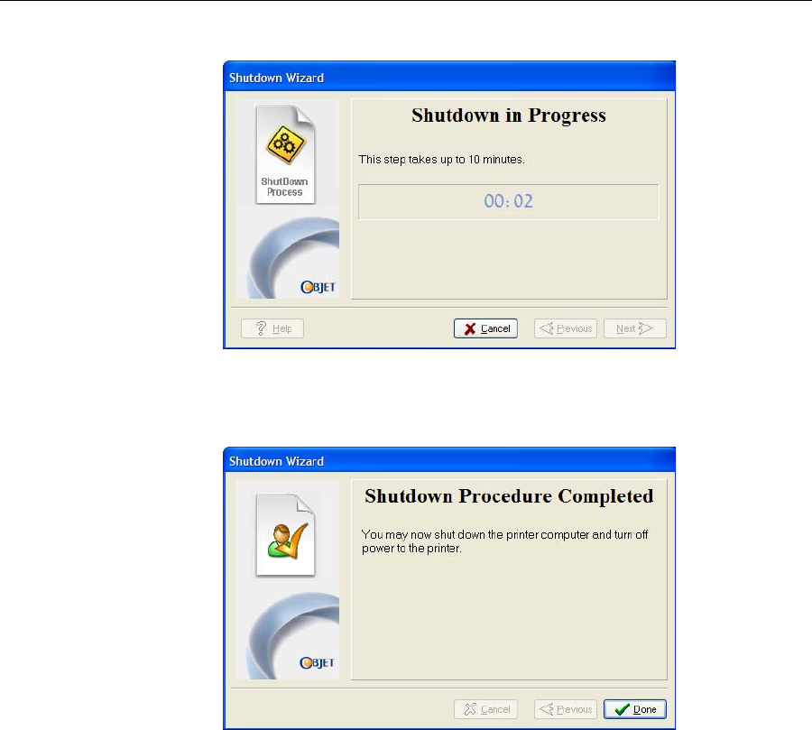
Theshutdownprocedurebegins.
Figure 7-17: Shutdown progress screen
5. Whenthefinalwizardscreenappears,closetheprinter‐control
applicationandshutdownthebuilt‐incomputer.
Figure 7-18: Final Shutdown Wizard screen
6. Aftertheprintercomputershutsdown,turnoffthemainpowerswitch
(atthebackoftheprinter)(seefigure 7‐2onpage 2).

Operating & Maintaining the Connex500/350 3-D Printer
7–18
DOC-13000 Rev. E
Maintaining the Connex Printer
Theperformanceofroutinemaintenancetasksisessentialforgetting
satisfactoryresultsfromConnex3‐Dprinters.Performthetasksat
specifiedintervalsforoptimumperformance.
Routine
Maintenance
Schedule
Frequency Task For More Information
Daily,beforeprinting Cleantheprintheads. See“CleaningthePrint
Heads”onpage 7‐19.
WeeklyCleanthebuildtrayand
thesurroundingarea.
Weekly PerformthePatterntest. See“PatternTest”on
page 7‐21.
Weekly Cleanandinspectthe
wiper. See“Cleaningand
ReplacingtheWiper”
onpage 7‐23.
Weekly RestarttheConnex
printercomputerand
theservercomputer.
Weekly Cleantherollerwaste
collector. See“CleaningtheRoller
WasteCollectorand
InspectingtheRoller
Scraper(Knife)”on
page 7‐25.
Every200hoursof
printing(Areminder
messageappears.)
TesttheUVlamps. See“Testingand
CalibratingtheUV
Lamps”onpage 49.
Monthly,andafter
replacingprintheads Checkthealignmentof
theprintheads. See“
AligningthePrint
Heads”onpage 7‐30.
MonthlyCalibratetheloadcells. See“Calibratingthe
LoadCells”on
page 7‐51.
Monthly Inspecttheexhaust
system(duct,fan,
connections).
Every2000hoursof
printing,oronceayear
Preventivemaintenance
visitbyauthorized
serviceengineer.
ContactyourObjet
supportcenter.
DOC-13000 Rev. E 7–19
Connex500/350 User Guide
Cleaning the
Print Heads Periodicinspectionandcleaningoftheorificeplatesonthebottomofthe
printblockensuresthattheprintnozzlesarenotclogged.Awizardguides
youthroughtheprocedure,andadjustscomponentsoftheConnexprinter
toenableyoutoperformit.Thisproceduretakesabout20minutes,and
shouldbedoneatthebeginningoftheworkdayorbeforeabigprinting
job.
To clean the print heads:
1. Prepare—
•isopropanol(IPA—isopropylalcohol)orethanol(ethylalcohol)
•disposablecleaninggloves
•anObjet‐suppliedcleaningclothorequivalent
•amirror
2. StarttheHeadsCleaningwizardfromtheOptionsmenuoftheprinter
interface(seefigure 7‐26onpage 23).
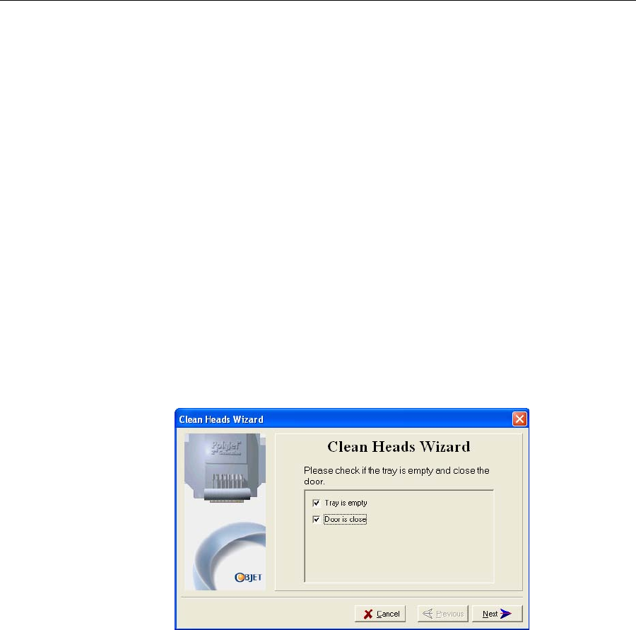
3. Followtheinstructionsonthewizardscreens,andselectthecheck
boxestoconfirmthat:
•youhavecheckedthatthetrayisempty.
•youhaveclosedthecover.
Figure 7-19: Head cleaning procedure—wizard screen
4. ClickNext.
Theprinterpreparesforyoutocleantheprintheads.
Operating & Maintaining the Connex500/350 3-D Printer
7–20
DOC-13000 Rev. E
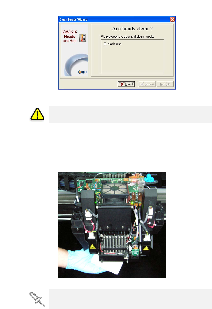
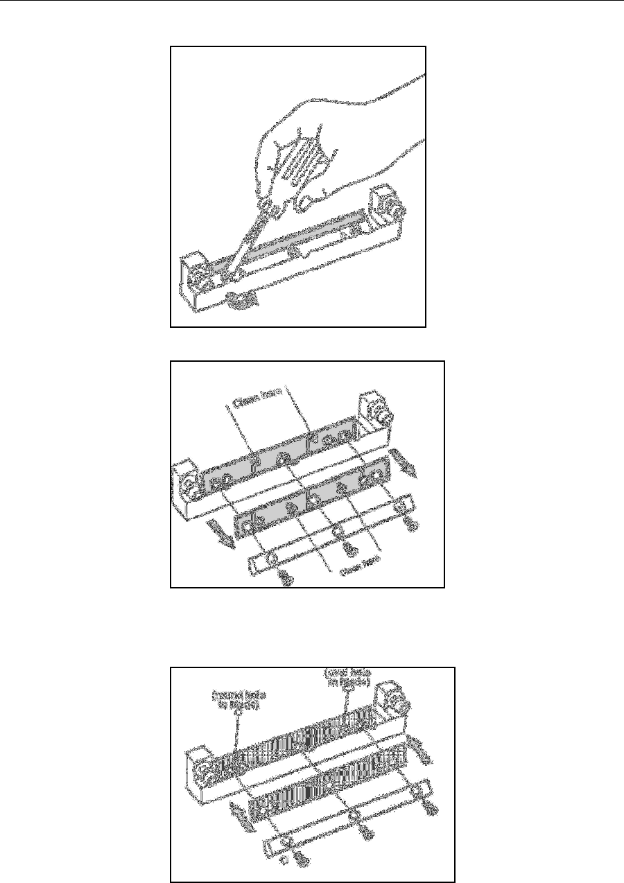
5. Whenthefollowingscreenappears,openthecover.
Figure 7-20: Head cleaning wizard—steps 5–10
6. Placethemirroronthebuildtray.
7. Putonthegloves.
8. Soakthecleaningclothwiththecleaningfluid.
9. Cleantheorificeplates,withaback‐and‐forthmotion(seefigure 7‐21).
Usethemirrortomakesurethatyouhaveremovedalloftheresidue
material.
Figure 7-21: Cleaning the heads
10. Whenyouhavefinishedcleaning,selecttheconfirmationcheckboxin
thewizardscreen(seefigure 7‐20)andclickNext.
WARNING: The print head orifice plates (bottom surface) may be hot.
Do not touch them with your bare hands, and proceed with caution.
It is recommended that you use this opportunity to also clean the roller and
the UV-lamp lens (to the right of the print heads).
DOC-13000 Rev. E 7–21
Connex500/350 User Guide
11. Removethecleaningmaterialsfromtheprinterandclosethecover.
12. Selecttheconfirmationcheckboxesinthewizardscreenandclick
Next.
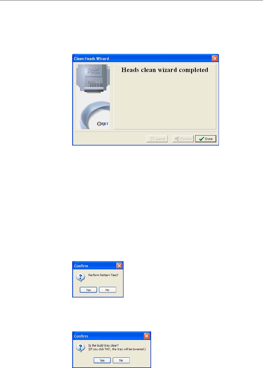
Thehead‐purgecyclebegins.Whenthisiscomplete,thefinalwizard
screenappears.
Figure 7-22: Head cleaning wizard—final screen
13. ClickDonetoclosethewizard.
Pattern Test Thepatterntestisthebasicverificationoftheprinter’sabilitytoproduce
qualitymodels,sinceitdemonstratestheconditionofthenozzlesinthe
printheads.Makesure,therefore,thatyouperformthistestweekly,and
wheneveryoususpectaprintingproblem.
To perform the pattern test:
1. Makesurethatthebuildtrayisempty.
2. Prepareasheetofpinkpaper—A‐4orLettersize.
3. IntheConnexprinter,tapethepinkpapertothesurfaceleftofthe
buildtray.
4. PressF3,oropentheOptionsmenuandselectPattern Test.
Figure 7-23: Pattern Test confirmation
5. Ifthebuildtrayisnotclear,clickNointhefollowingdialogbox.
Thislowersthebuildtray,sothatmodelsonthetrayarenotdamaged.
Figure 7-24: Build tray (Z) level adjustment
TheConnexprinterprintsaseriesoflinesonthetestpaper.
Operating & Maintaining the Connex500/350 3-D Printer
7–22
DOC-13000 Rev. E
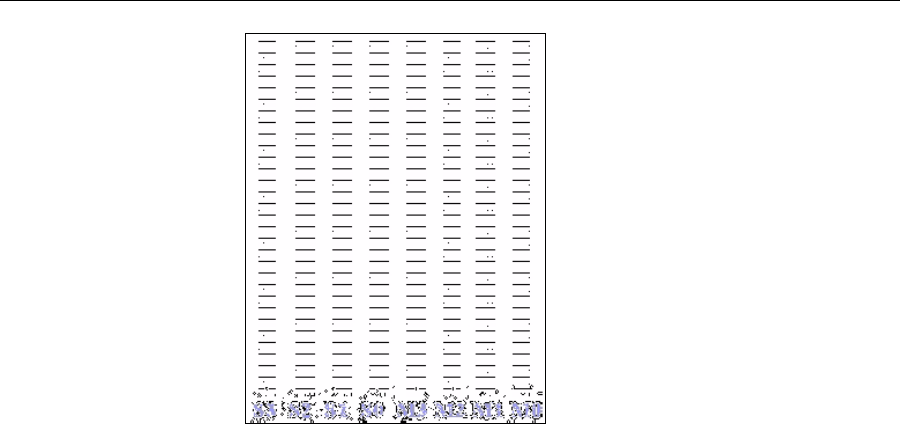
Figure 7-25: Sample Pattern Test
6. Carefullyinspectthetestpapertoseeiftherearemissinglines.
Toomanymissinglines,especiallyiftheyareinthesamearea,
indicatesthatthequalityofprintingwhenproducingmodelswillbe
poor.Ifthisisthecase,see“ImprovingPrintQuality,”below.
Note: Acceptable model quality is subjective, and depends on the type
and scale (size) of the models produced. As a rule, however, more than 10
missing lines in one area of a column is considered unacceptable.
Improving
Print Quality Ifyoususpectthatprintqualityispoor,performthepatterntest(see
“PatternTest”onpage 7‐21).Iftheresultsarepoor,usethefollowing
proceduretoimproveprintquality.
If the results of the last pattern test are poor:
1. FromtheOptionsmenu,selectExecute Purge Sequence,orpressF4.
2. Intheconfirmationdialogbox,clickYes.
Theprintheadsarepurgedofmodelandsupportmaterial,andthe
wiperremovesexcessmaterialfromthem.
3. Repeatthepurgesequence.
4. Performthepatterntest.
If the results of the pattern test are still poor:
1. Manuallycleantheprintheads(see“CleaningthePrintHeads”on
page 7‐19).
2. Performthepurgesequence.
3. Performthepatterntest.
If the results of the pattern test are still poor:
1. Carefullycleantheprintheadsagain,makingsurethereisnoresidue
leftonthem.
2. Performthepurgesequence.
3. Performthepatterntest.
If the results of the pattern test are still poor:
¾Replacefaultyprintheads(see“ReplacingPrint Heads”onpage 7‐40).
DOC-13000 Rev. E 7–23
Connex500/350 User Guide
Cleaning and
Replacing the
Wiper
Arubberwiperremovesexcessmaterialfromtheprintheadsafterthe
purgesequence.Thisisdoneautomaticallybeforeeachprintjob,and
performedmanuallyduringmaintenancetasks.Youshouldcleanthe
wiperandsurroundingareaatleastonceaweek.Ifthewiperisdamaged
orworn,replaceit.
To inspect and clean the wiper:
1. Prepare—
•isopropanol(IPA—isopropylalcohol)orethanol(ethylalcohol)
•disposablecleaninggloves
•anObjet‐suppliedcleaningclothorequivalent
•asparewiper
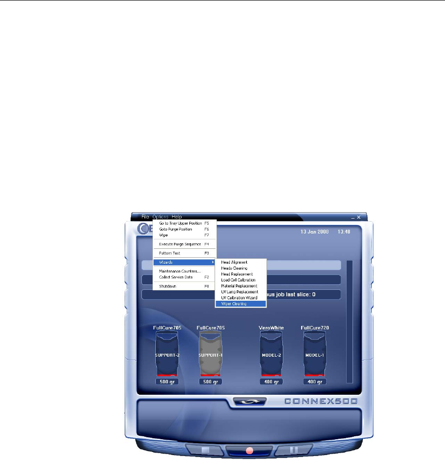
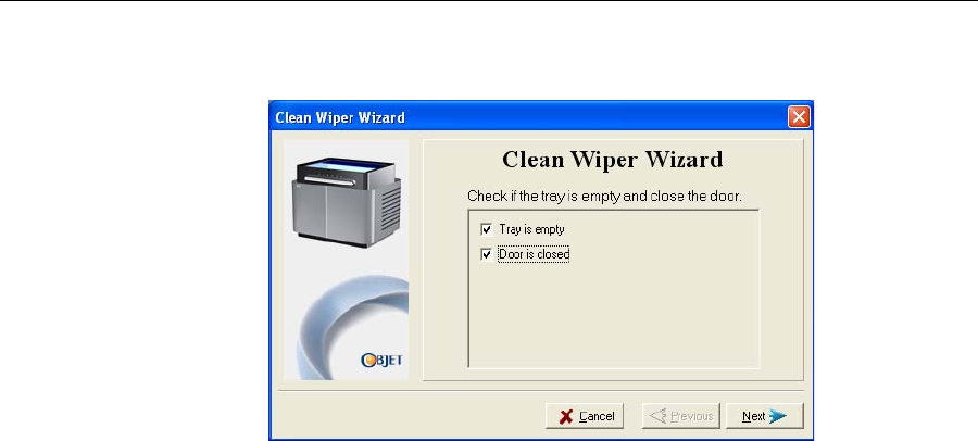
2. StarttheWiperCleaningwizardfromtheOptionsmenuoftheprinter
interface.
Figure 7-26: Starting the Wiper Cleaning wizard
3. Closetheprintercover,andclickNextinthewizardscreen.
4. Makesurethatthebuildtrayisempty,andclosetheprintercover.
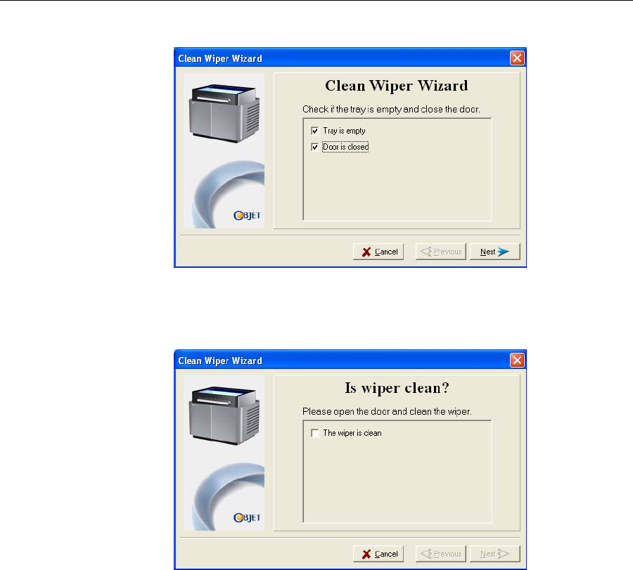
Operating & Maintaining the Connex500/350 3-D Printer
7–24
DOC-13000 Rev. E
Confirmthisinthewizardscreen.
Figure 7-27: Wiper Cleaning procedure—step 4
5. ClickNext.
6. Whenthefollowingscreenappears,openthecover.
Figure 7-28: Wiper Cleaning wizard during steps 7–10
7. Putonthecleaninggloves.
8. Usingagenerousamountofcleaningfluidandthecleaningcloth,
removeanymaterialremainingonthewiperandthesurrounding
area.
9. Inspectthewiper.
Ifthewiperisscratched,tornorworn,orifyoucannotcleanit
completely,replaceit.
a. Graspitandpullitupandoutofitsbracket.
b. Insertthenewwiperblade,makingsurethatitisstraightandsecured
wellonbothsides.
10. Inthewizardscreen(seefigure 7‐28),confirmthatthewiperbladeis
clean,andclickNext.
11. Makesurethatyouhaveremovedalltoolsandcleaningmaterials
fromtheprinter,andclosethecover.
DOC-13000 Rev. E 7–25
Connex500/350 User Guide
12. Selecttheconfirmationcheckboxesinthewizardscreenandclick
Next.
Figure 7-29: Wiper Cleaning procedure—final confirmation screen
13. ClickDonetoclosethewizard.
Cleaning the
Roller Waste
Collector and
Inspecting the
Roller Scraper
(Knife)
Therollerwastecollectorremoveswastematerialscrapedfromtheroller.
Suctionremovesthiswastetotheprinter’swastecontainer.
Thisassemblyshouldbecleanedweeklytopreventablockageinthetubes
leadingtothewastecontainer,sothatwastematerialdoesnotoverflow
intotheprinter.
To clean the roller waste collector:
1. Prepare—
•M2.5andM2Allenkeys
•disposablecleaninggloves
•isopropanol(IPA—isopropylalcohol)orethanol(ethylalcohol)
•cleaningcloth
•cottonswabs(Q‐tips®orsimilar)
2. Putonthegloves.
Operating & Maintaining the Connex500/350 3-D Printer
7–26
DOC-13000 Rev. E
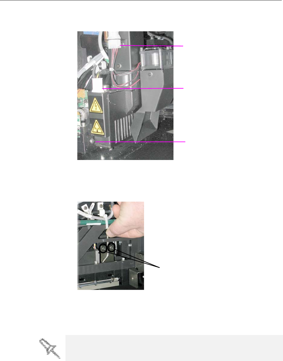
3. RemovetherightUV‐lampassembly:
a. DisconnecttheUVpowercableandthefanpowercable.
Figure 7-30: Disconnecting the right UV assembly
b. RemovethescrewattachingtherightUVlamptotheprintblock,
andthenpullandliftuptheUVlamp.
4. Loosenthetwoscrewssecuringthesuctiontubeontheprintblock
Figure 7-31: Lifting the suction tube
5. Liftthesuctiontubetosecureitinaraisedposition.
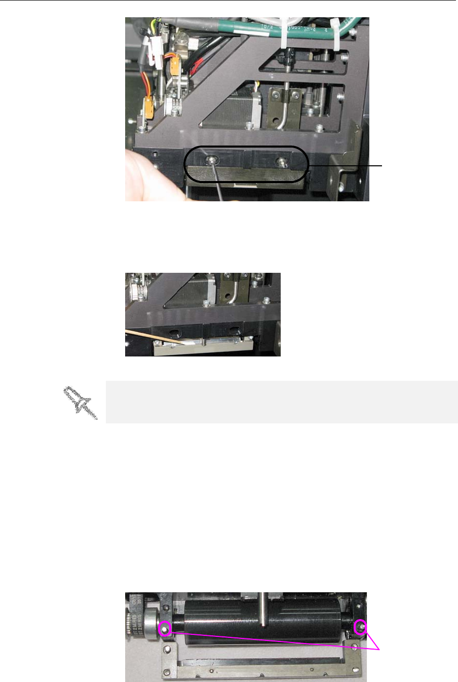
6. Removethetwoscrewssecuringthecoveringoftherollerwaste
collectorandremoveit.
Fan power
connector
Power connector
Screw
Suction tube screws
Be very careful to save the covering screws. These are special screws, if
they are lost you need to order replacements.
DOC-13000 Rev. E 7–27
Connex500/350 User Guide
Figure 7-32: Removing the roller waste collector covering
7. Removethecoveringbypullingitout,andthenlowerit.
8. Cleantherollerwastecollectorandthescraperbladesurfaceusing
cottonswabs.Makesuretoremoveanyremainingprintingmaterials.
Figure 7-33: Cleaning the roller waste collector
To check the effectiveness of the roller scraper:
1. Putonthecleaninggloves.
2. Wetaclothwithisopropanol.
3. Usetheclothtowetthebottomoftheroller.
4. Turntherollerslowlywithyourhand.Asthebladescrapestheroller,
makesuretheisopropanolisspreadevenlyovertheentirelengthof
theblade
5. Inspecttheroller.Ifitisnotdry,replacetheblade.
6. Beforereturningtherollerwastecollectortotheprintblock,makesure
thatthepinsitrestsuponareclean.
Figure 7-34: Roller waste collector pins
Roller waste
collector screws
Before replacing the covering you can check the effectiveness of the roller
scraper (knife)—see below.
Roller waste
collector pins
Operating & Maintaining the Connex500/350 3-D Printer
7–28
DOC-13000 Rev. E
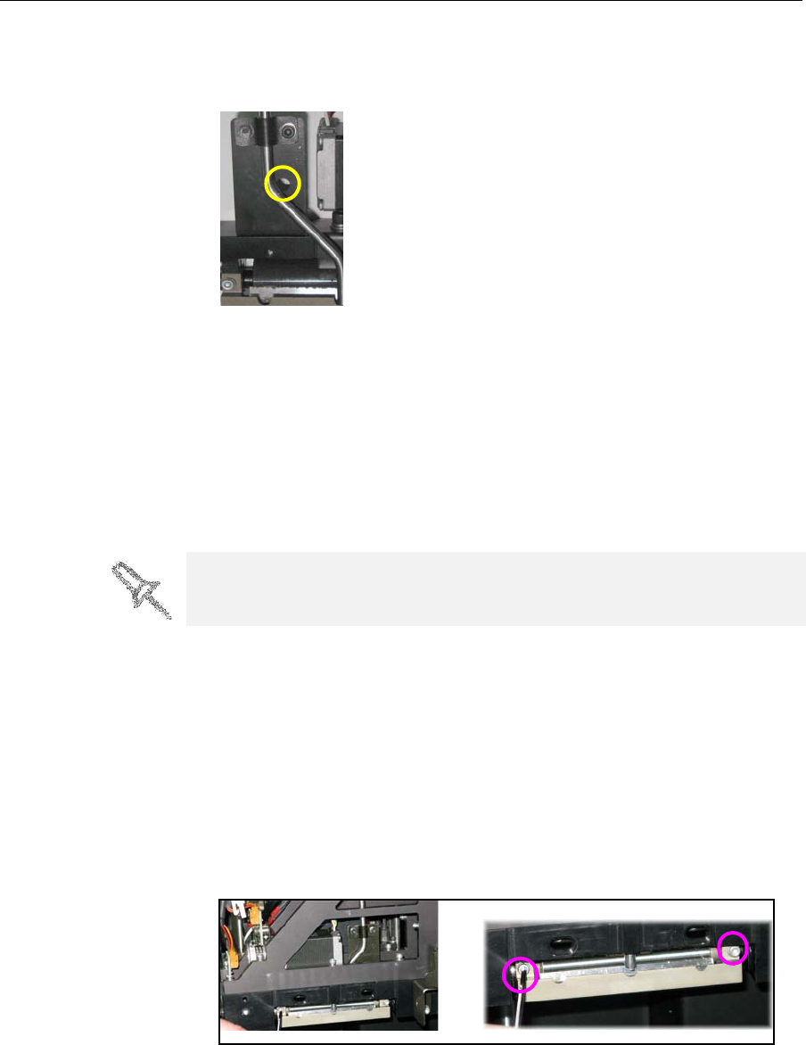
7. Returntherollerwastecollectortotheprintblockandscrewonthe
covering(seefigure 7‐32onpage 7‐27).
8. Loosenthescrewssecuringthesuctiontube.
Figure 7-35: Suction tube correctly positioned
9. Loweritsothattheholeinthepanelbehindthesuctiontubeisvisible,
andtightenthescrewstosecurethesuctiontube.
10. Attachtheright‐UV‐lampassemblytotheprintblockandreconnect
theUVpowerandfancables.
Replacing the
Roller Scraper
(Knife)
Youshouldreplacetherollerscraperblade:
•after1,000hoursofprinting.
•ifitdoesnoteffectivelykeeptherollerclean.
To replace the roller scraper:
1. Prepare—
•anewrollerscraper(knife)(Kit‐01026‐S)
•aPhillips1x75mmscrewdriver
•M2.5andM2Allenkeys
2. RemovetherightUVlampandtherollerwastecollectorcovering(see
steps3to6onpage 7‐26.)
3. Loosenthetwoscrewssecuringtherollerwastecollectorandpullit
out.
Figure 7-36: Removing the roller waste collector
You should periodically test the effectiveness of the roller scraper when you
clean the roller waste collector. See “Cleaning the Roller Waste Collector
and Inspecting the Roller Scraper (Knife)” on page 25.
DOC-13000 Rev. E 7–29
Connex500/350 User Guide
4. Removethescrewsthatsecuretherollerscraperassembly.
Figure 7-37: Removing the roller scraper screws
Figure 7-38: Removing the old roller scraper blade
5. Removethescraperbladeanddiscardit.
6. Placethenewscraperbladeontothepinsintheholder,asshown.
Figure 7-39: Inserting the new roller scraper blade
Operating & Maintaining the Connex500/350 3-D Printer
7–30
DOC-13000 Rev. E
7. Insertandtightentherollerscraperbladescrews.
Figure 7-40: Tightening the roller scraper screws
8. Aftertighteningthescrews,inspectthebladeandmakesurethatitis
straight.Ifnecessary,loosenthescrewsandtightenthemagain,evenly.
9. ReturntherollerwastecollectorassemblyandtherightUVlampto
theprintblock.Seesteps6to10frompage 7‐27.
Aligning the
Print Heads Youshouldcheckthealignmentoftheprintheads—
•onceamonth
•afterreplacingoneormoreheads
•ifmodelqualityisnotacceptableevenaftercleaningtheorificeplateon
thebottomoftheprintblock(see“CleaningthePrintHeads”on
page 7‐19)
Thehead‐alignmentproceduretakesabout20minutes.
To check the alignment of the print heads:
1. Prepare—
•atransparencysheet—A‐4orLettersize
•anytypeofstickytape,tofastenthetransparencysheettothebuild
tray
2. StarttheHeadAlignmentwizard,fromtheConnexOptionsmenu(see
figure 7‐26onpage 23).
3. ClickNexttobegin,andclosethecover.
4. Inthewizardscreen,selectthecheckboxtoconfirmthatthecoveris
closed,andclickNext.
Important:
•Tighten the screws in the order shown in Figure 7-40.
•Use the new screws supplied in the replacement-kit.
DOC-13000 Rev. E 7–31
Connex500/350 User Guide
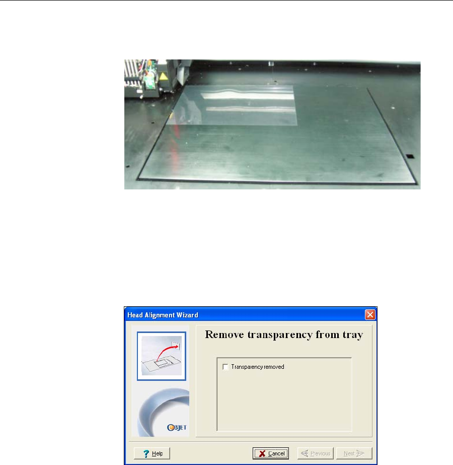
5. Wheninstructedtodoso,placethetransparencyonthebuildtray—
nexttotheleftandrearedgesofthetray,asshowninthefollowing
figure.
Figure 7-41: Positioning the transparency on the build tray
6. Makesurethatthetransparencysheetislyingflat,andtapeittothe
tray.
7. Inthewizardscreen,selectthecheckboxtoconfirmthatthe
transparencysheetisonthebuildtray,andclickNext.
TheConnexprinterprintstheheadalignmenttestonthetransparency.
8. Whenthefollowingscreenappears,removethetransparency.
Figure 7-42: Head Alignment wizard—steps 8–10
Operating & Maintaining the Connex500/350 3-D Printer
7–32
DOC-13000 Rev. E
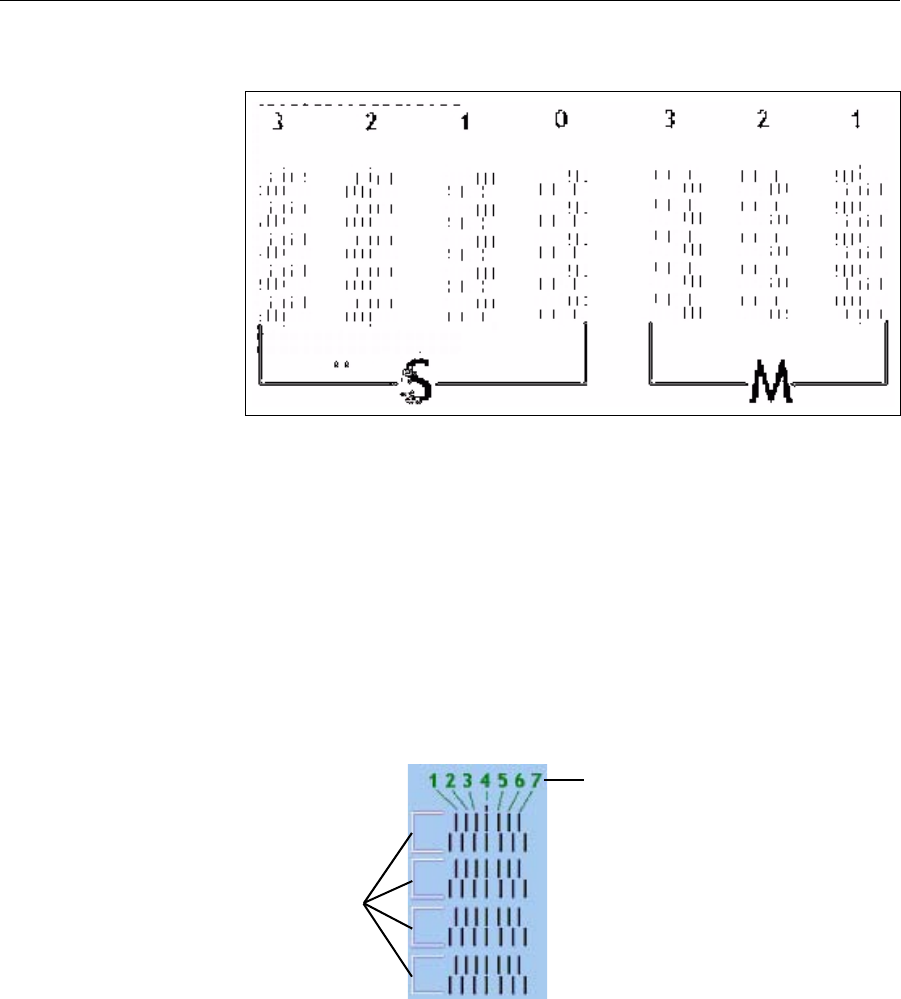
Thetransparencysheetisprintedwithsetsofverticallinesinseven
columns,eachshowingtheresultsfromadifferentprinthead.
Figure 7-43: Sample head-alignment test
•Thethreecolumnsontherightwereprintedbytheheadsusedfor
applyingmodelmaterialwhenproducingmodels.Fromrightto
left,thecolumnsrepresentheadsM1,M2,M3,respectively.(There
isnocolumnforheadM0becauseitsalignmentisusedasa
referenceforaligningallotherheads.)
•Thefourcolumnsoflinesontheleftwereprintedbytheheadsused
forapplyingsupportmaterial.ThecolumnsrepresentheadsS3,S2,
S1andS0,respectively.
9. Foreachcolumnoflines,useamagnifyingglassorloupetoinspect
pairsofconsecutiverowsprintedonthetransparencytoseewherethe
verticallinesalign.
Figure 7-44: Comparing rows of alignment lines
Note: It does not matter which pair of lines you inspect, since they were all
printed by the same head. Choose a pair of clearly printed lines for the
inspection. (Since some nozzles may not print clearly, you may have to
inspect several pairs of lines to properly view the alignment.)
Optimumheadalignmentisshownwhenthefourthlinesintheupper
andlowerrowsarealigned,asinfigure 7‐44.Intheexampleshown,no
changetotheheadalignmentisnecessary.Ifotherlinesinthesetare
aligned,youneedtochangethealignmentofthathead—inthenext
wizardscreens.
10. Inthewizardscreenshowninfigure 7‐42,selecttheTransparency
removedcheckbox,andclickNext.
Alignment-line
numbering, left-to-right
Row pairs
DOC-13000 Rev. E 7–33
Connex500/350 User Guide
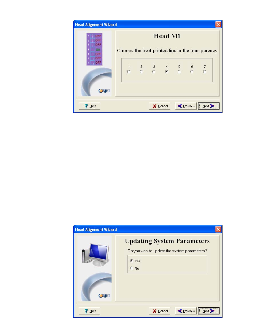
Thefirstinaseriesofalignmentscreensappears.
Figure 7-45: Head alignment screen
11. Inthehead‐alignmentscreen,selectthenumberthatindicateswhich
linesalignintheupperandlowerrowsofapaironthetransparency
(countingfromtheleft)forthisprinthead.
Note: Because the alignment of the fourth lines is optimum, the number “4”
is selected, by default, in the wizard screen. This does not change the head
alignment. If you select other numbers, the wizard adjusts the head
alignment, accordingly.
12. ClickNexttodisplaythenextheadalignmentscreen,andagainselect
thenumberrepresentingthemostcloselyalignedverticallinesonthe
transparencyforthatprinthead.
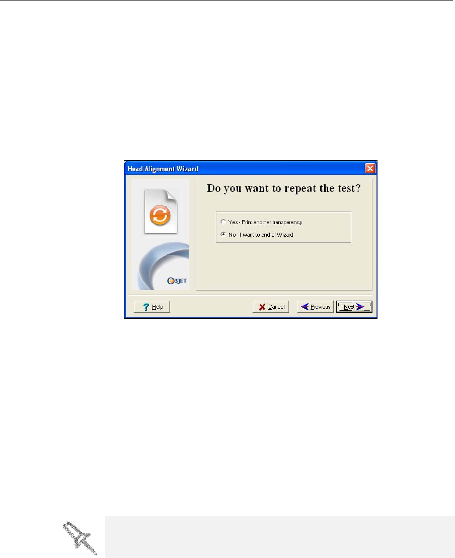
Whenyouhavefinishedaligningalloftheheads,thefollowingscreen
isdisplayed.
Figure 7-46: Updating System Parameters confirmation screen
13. Continueasfollows:
•Tomakethealignmentchangesintheprinter,makesurethatYesis
selected,andclickNext.
•Torecheckthealignmenttestresultsbeforemakingthealignment
changesintheprinter,clickPrevious.
•Ifyoudonotwanttomakealignmentchangesintheprinteratthis
time,selectNoandclickNext.
Operating & Maintaining the Connex500/350 3-D Printer
7–34
DOC-13000 Rev. E
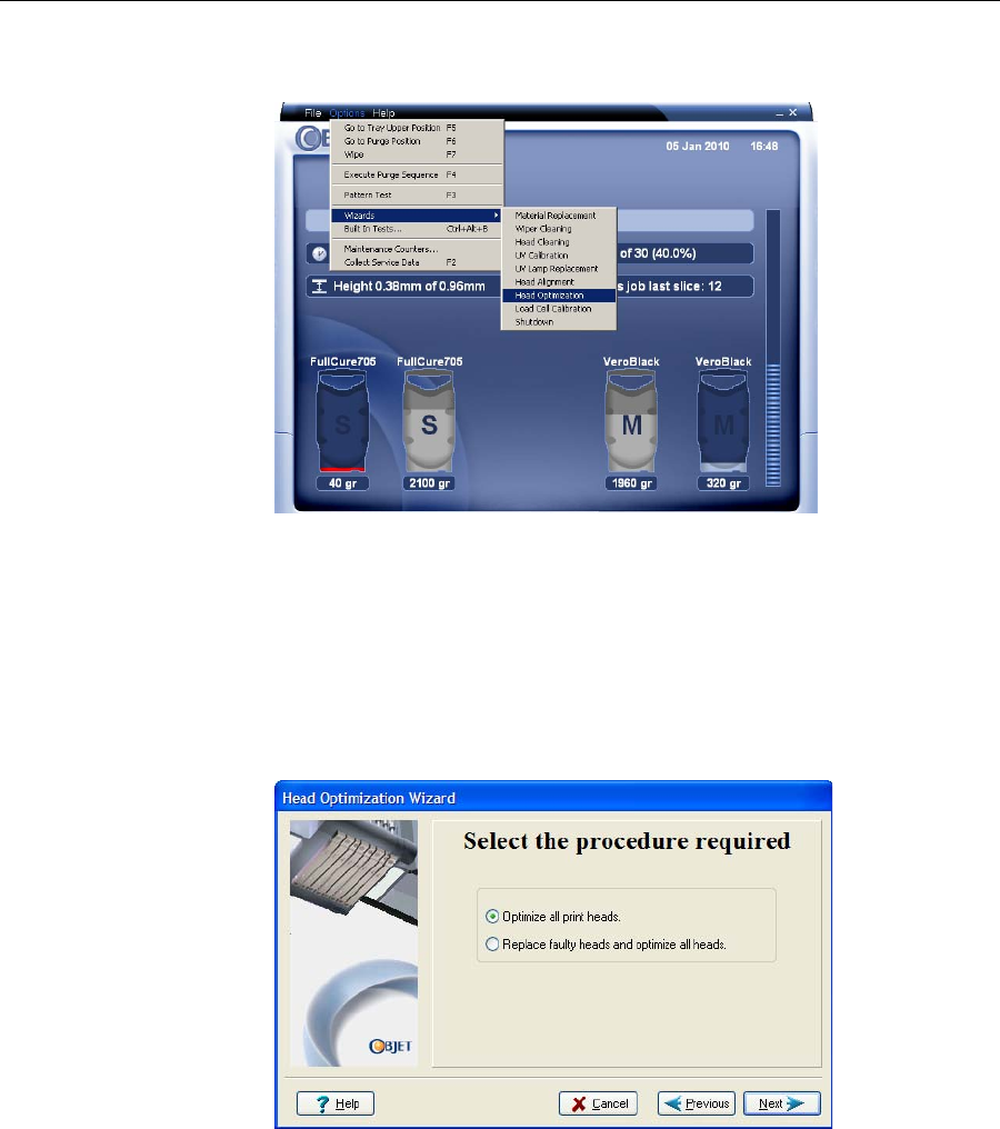
14. Inthefinalwizardscreen,choosetoeitherrepeattheheadalignment
procedureorclosethewizard.
•Ifthemostcloselyalignedverticallinesforaprintheadwereat
eitherextreme—thefirstorseventhlines—chooseYestorunthe
head‐alignmentwizardagain,thenclickNext.
Thetransparencytestwillshowiftheheadsarenowproperly
aligned,and—ifnot—thewizardwillallowyouto“finetune”the
alignment.
•Iftheverticallinesfortheprintheadswerenotalignedateither
extreme,chooseNotoclosethewizard,thenclickNext.
Figure 7-47: Final wizard screen
Calibrating
Print Heads Theconditionoftheprintheadsdirectlyaffectsthequalityofprinted
models.Tomaintainoptimumprinting,youshouldroutinelytesttheprint
heads,andcalibratethemtothebestworkingconfigurationpossible.You
dothisbyrunningtheHeadOptimizationwizard.
Duringtheoptimizationprocess,32samplesareprintedonthebuildtray.
Aftercarefullyweighingeachofthem,youentertheweightinthewizardʹs
data‐entryscreen.Thewizardusesthisdatatooptimizetheheads.
If,duringtheoptimizationprocess,thewizarddeterminesthataprinthead
isfaulty—orthatitisnegativelyaffectinglayeruniformitywiththecurrent
headconfiguration—thewizardinstructsyoutoreplaceit.Ifthishappens,
youcancontinuethewizard(toreplacetheprinthead)orabortthewizard
(toreplacetheheadatanothertime).
To test and calibrate the print heads:
1. Prepare—
•isopropanol(IPA—isopropylalcohol)orethanol(ethylalcohol)
•disposablecleaninggloves
•anObjet‐suppliedcleaningclothorequivalent
•amirror
•thescalesuppliedbyObjetforuseintheWeightTest
Run the Head Optimization Wizard whenever the condition of print heads is
negatively affecting the quality of printed models, or if you suspect that there
is a problem with one or more of the print heads.
DOC-13000 Rev. E 7–35
Connex500/350 User Guide
2. StarttheHeadOptimizationwizardfromtheOptionsmenuofthe
printerinterface.
Figure 7-48: Starting the Head Optimization wizard
3. Intheopeningwizardscreen,clickNexttobegin.
TheWizardConditionsscreenappears.
4. Readtheconditions,selectIAgreeandclickNext.
5. Closetheprintercover,andconfirmthisinthewizardscreen.
6. Inthefollowingscreen,makesureOptimizeallprintheadsisselected,
andclickNext.
Figure 7-49: Procedure selection screen
Theprintblockmovesintopositionforcleaningandinspectingthe
printheads.
Operating & Maintaining the Connex500/350 3-D Printer
7–36
DOC-13000 Rev. E
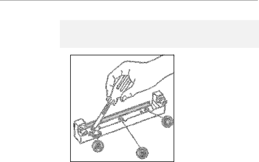
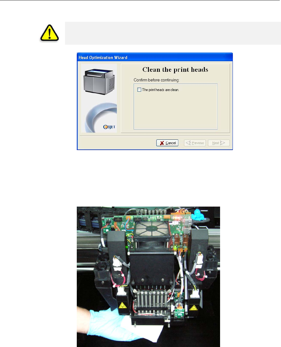
7. Whenthefollowingscreenappears,cleantheprintheads.
Figure 7-50: Clean print heads screen
8. Placethemirroronthebuildtray.
9. Putonthecleaninggloves.
10. Soakthecleaningclothwiththecleaningfluid(alcohol).
11. Cleantheorificeplates,withaback‐and‐forthmotion.
Figure 7-51: Cleaning the print heads
Usethemirrortomakesurethatyouhaveremovedalloftheresidue
material.
12. Whentheprintheadsareclean,selecttheconfirmationcheckboxin
thewizardscreenandclickNext.
13. Removethecleaningmaterialsfromtheprinter,andclosethecover.
14. SelecttheconfirmationcheckboxinthewizardscreenandclickNext.
WARNING: The print head orifice plates (bottom surface) may be hot.
Do not touch them with your bare hands, and proceed with caution.
DOC-13000 Rev. E 7–37
Connex500/350 User Guide
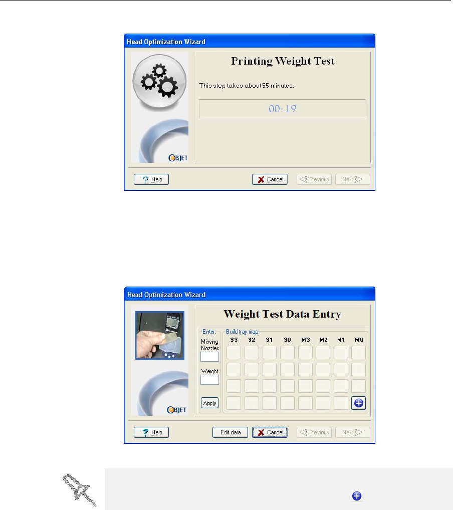
Thehead‐purgecycleruns,afterwhichtheWeightTestisprinted.
Figure 7-52: Printing Weight Test
15. 32samplesareprintedonthebuildtray,fourforeachoftheprint
heads.Thiscantakeupto55minutes.
16. Whenthefollowingscreenappears,opentheprintercover.Enterthe
datathatdescribestheconditionofeachprinthead,afterinspecting
eachoftheprintedsamples.
Figure 7-53: Weight Test Data Entry screen
a. Enterthenumberoffaulty(“missing”)nozzles.
FaultynozzlesareseeninWeightTestsamplesasamissingrowof
printedmaterial.Comparetheheightofthemissingrowwiththe
linesprintedonthe“missingnozzles”ruler.Enterthenumbernext
tothelinethatmostcloselymatchestheheightofthemissingrow.
The layout of the data entry screen matches the printed samples on the
build tray. Enter the data for the sample indicated by in the screen.
Operating & Maintaining the Connex500/350 3-D Printer
7–38
DOC-13000 Rev. E
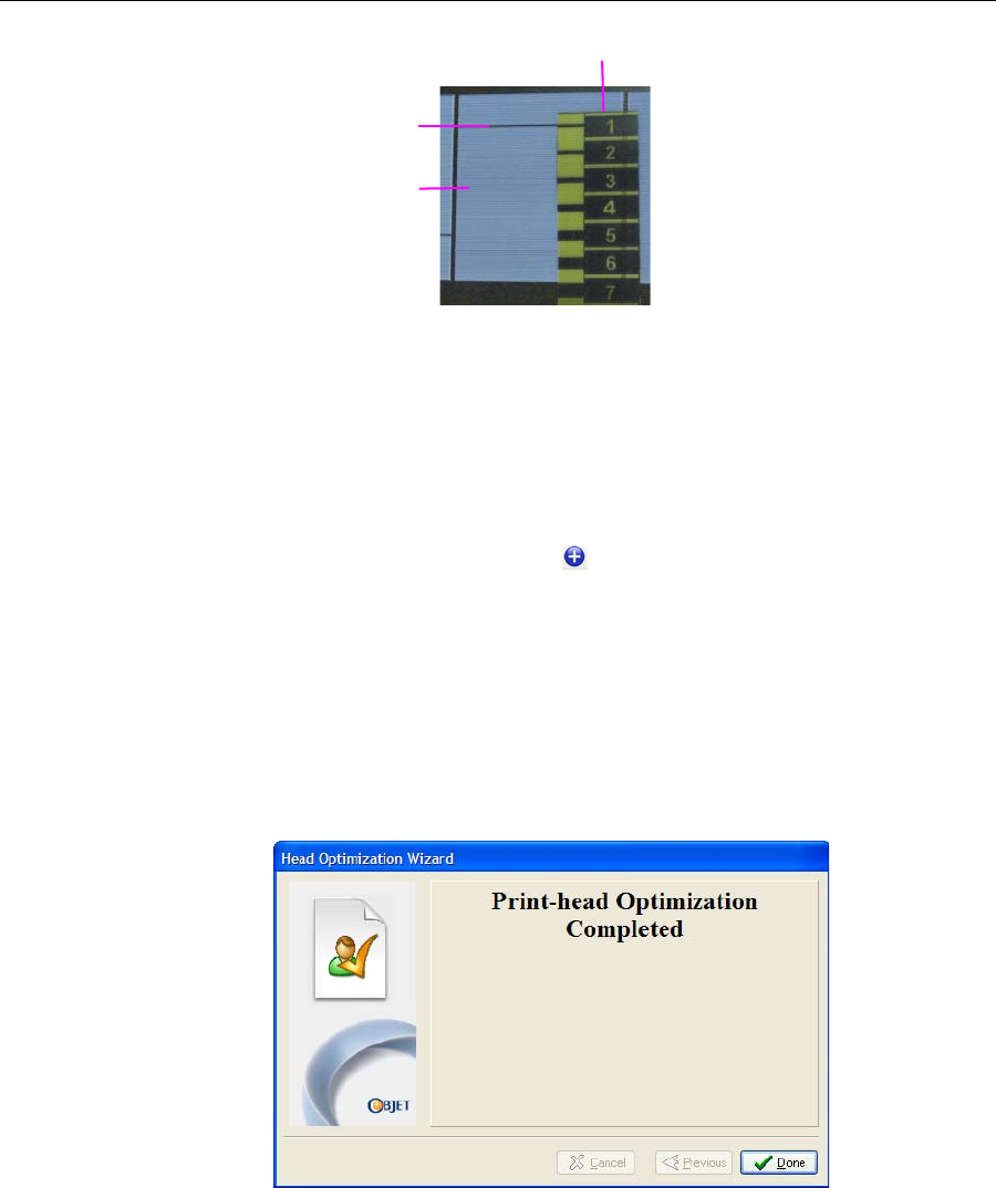
Figure 7-54: Measuring the missing line in a printed sample
Intheexampleabove,youwouldenter“1”inthewizardscreen.
b. Carefullyremovethesample,weighit,andentertheweightinthe
wizardscreen.
Besuretoremoveandweightheentiresample,evenifitbreaksinto
severalpieces.
c. ClickApplyorpressEnter.
Thedata‐entry‐indicator movestothenextposition.
d. Repeatthesestepsforall32samples.
To change an entry, click Edit Data, enter the correct data, and click Save.
17. Whenyouhaveenteredtheallofthedatainthewizardscreen,
click Next.
Thewizardusesthedatayouenteredtoanalyzetheconditionofthe
printheads,andoptimizesthemsotheyprintmodelswithauniform
layerofmaterial.Iftheheadsareinsatisfactorycondition,thefinal
wizardscreenappears.
Figure 7-55: Final wizard screen, after optimizing print heads
Missing line
Printed sample
Ruler
DOC-13000 Rev. E 7–39
Connex500/350 User Guide
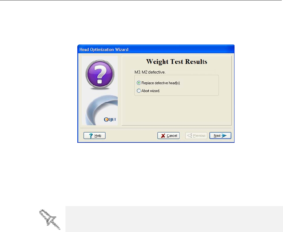
However,ifthewizarddeterminesthataprintheadisfaulty—orthatit
isnegativelyaffectingmodelqualitywiththecurrenthead
configuration—thewizardinstructsyoutoreplaceit.Inthiscase,the
followingscreenappears.
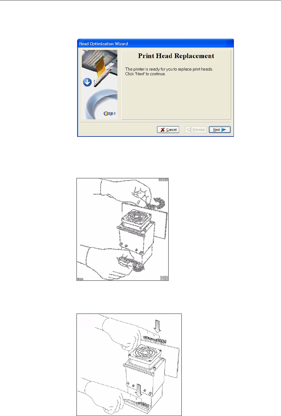
Figure 7-56: Defective print heads found
18. ChooseReplacedefectivehead(s)ifyouarepreparedtoreplacetheprint
headsnow.
or—
ChooseAbortwizardifyouwanttoreplacetheprintheadsatanother
time.
Ifyouarereplacingtheprintheadsnow,thewizardguidesyouthroughthe
procedurewhenyouclickNext.Continuewith“Preparingtheprint block”
onpage 41.
Replacing print heads is expensive. Replace them only after consulting with
an Objet-authorized customer-support engineer.

Operating & Maintaining the Connex500/350 3-D Printer
7–40
DOC-13000 Rev. E
Replacing
Print Heads Theconditionoftheprintheadsdirectlyaffectsthequalityofprinted
models.Youneedtoreplaceaprintheadifoneormoreofthefollowing
symptomsoccurs:
•TheHeadOptimizationwizarddeterminesthatoneormoreprint
headsaredefective.(See“CalibratingPrintHeads”onpage 34.)
•Therearenoticeablegroovesinthesurfaceofprintedmodels.
•Visualinspectionoftheheadrevealsthatitssurfaceisdamaged—
peelingorbubblesinthenozzlearea.
•TheConnexinterfacedisplaysawarningormalfunctionmessage
relatingtoaprinthead—
HeadHeatertemperaturetimeout
HeadHeaterthermistoropen
HeadHeaterthermistorshort
TheHeadOptimizationwizardguidesyouthroughtheprocedureof
replacingaprinthead,andadjustscomponentsoftheConnexprinterto
enableyoutoperformit.Onlyreplaceaprintheadwiththeaidofthe
wizard.Theproceduretakes75—90minutes,andconsistsofthefollowing
phases:
A. Identifyingthehead(s)needingreplacement.
ThisisnormallydonebytheHeadOptimizationwizard.Otherwise,
evidenceofphysicaldamagetotheheadsurfaceoramalfunction
messageindicateswhichheadneedsreplacing.
B. Preparingtheprintblockforheadreplacement.
Thisisdoneautomaticallywhenyourunthewizard.
C. Removingthedefectiveprinthead.
D. Installinganewprinthead.
E. Optimizingtheprintheads(doneautomaticallybythewizard).
F. Performingheadalignment.
To replace a print head:
1. Prepare—
•replacementprinthead(s)
•isopropanol(IPA—isopropylalcohol)orethanol(ethylalcohol)
•disposablesafetygloves(includedintheheadreplacementkit)
•anObjet‐suppliedcleaningclothorequivalent
•aflat‐headscrewdriver(5mm)
•thescalesuppliedbyObjetforuseintheWeightTest
Note: Make sure that you have these items before running the wizard.
2. StarttheHeadOptimizationwizardfromtheOptionsmenuofthe
printerinterface(seefigure 7‐48onpage 35).
3. Intheopeningwizardscreen,clickNexttobegin.
Replacing print heads is expensive. Replace them only after consulting with
an Objet-authorized customer-support engineer.
DOC-13000 Rev. E 7–41
Connex500/350 User Guide
TheWizardConditionsscreenappears.
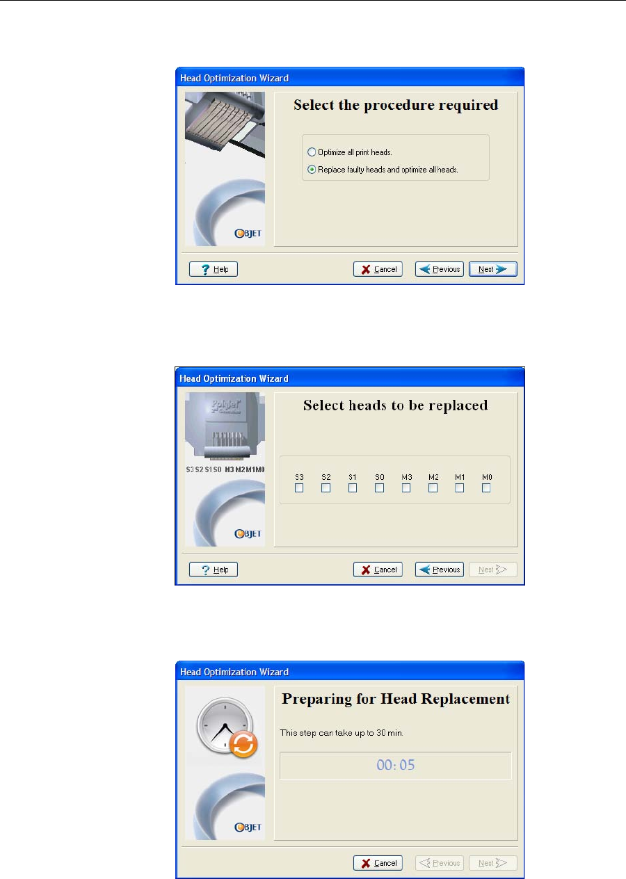
4. Readtheconditions,selectIAgreeandclickNext.
Figure 7-57: Procedure selection screen
5. ChooseReplacefaultyheads,andclickNext.
Preparing the
print block
6. Selecttheprinthead(s)needingreplacement,andclickNext.
Figure 7-58: Head selection screen
TheConnexprinterheatsandemptiestheprintblock,andpreparesthe
printer.(Thisshouldtakeupto30minutes.)
Figure 7-59: Printer preparation progress screen
7. Putonthesafetygloves.
Operating & Maintaining the Connex500/350 3-D Printer
7–42
DOC-13000 Rev. E
8. Whenthefollowingscreenisdisplayed,opentheConnexprinter
cover.
Note: The Connex printer disconnects power to the heads for your safety.
Figure 7-60: Replace the defective head when this screen appears
Removing the
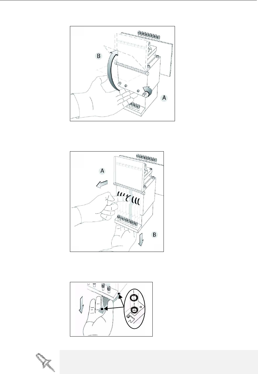
Defective Head 9. Ontheprintblock,releasetheupperandlowerscrewsthatsecurethe
printheadintheblock.(Ifnecessary,youmayuseascrewdriverto
loosenthescrews.)
Figure 7-61: Releasing the locking screws
10. Pressdownontheupperandlowerlockingscrewstoreleasetheprint
head.
Figure 7-62: Releasing the print head
DOC-13000 Rev. E 7–43
Connex500/350 User Guide
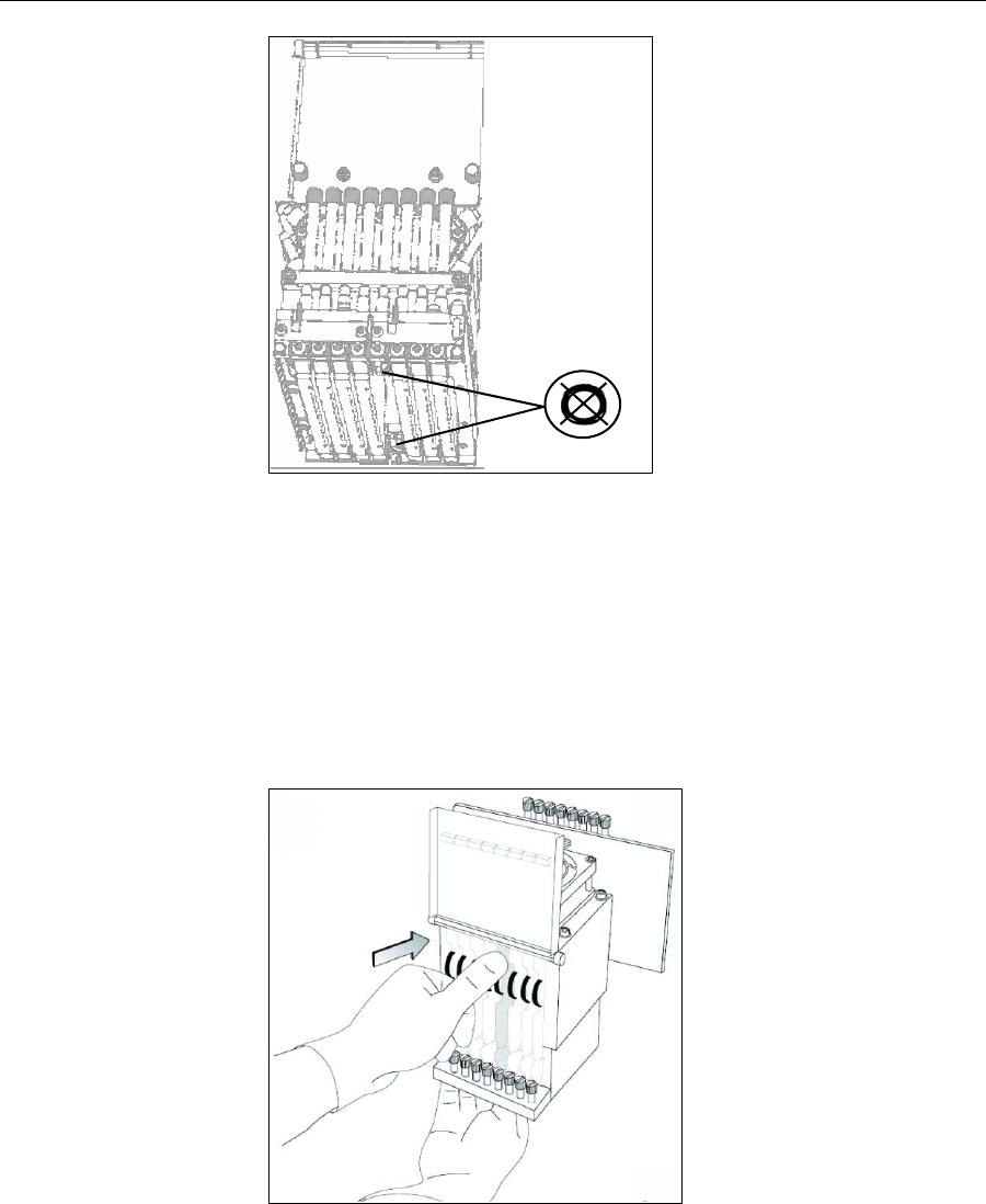
11. Loosenthescrewsonthedoorofthecompartmentprotectingthe
print‐headdrivercards(A),thenpullandliftupthedoor(B).
Figure 7-63: Opening the print-head compartment
12. Pulltheprint‐headdrivercardoutofitssocketsothattheheadisfree
(A),andremoveitfromthebottomoftheprintblock(B).
Figure 7-64: Releasing the print-head driver card to remove the head
13. Makesurethatalongwiththehead,youremovethetworubberO‐ring
seals.
Figure 7-65: O-ring seals on the print head
Important: If the seals are not removed with the head, they are probably
stuck to the print block housing. If so, remove them.
Operating & Maintaining the Connex500/350 3-D Printer
7–44
DOC-13000 Rev. E
Figure 7-66: Making sure the O-rings are not stuck to the print block
Installing the
New Head Important:Removetheprotectivetapefromthesurfaceofthe
newprinthead.
14. Inspectthereplacementhead,andmakesurethattheO‐ringsealsare
inplace(seefigure 7‐65).
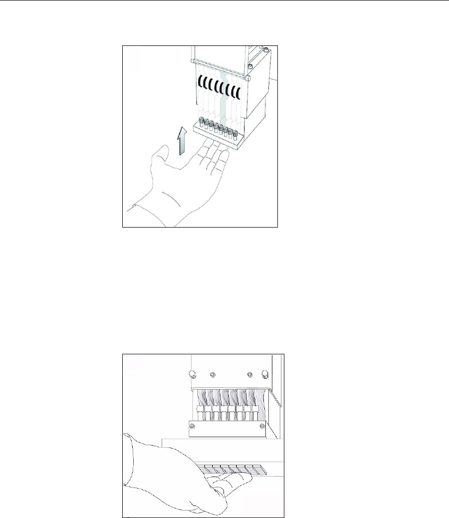
15. Gentlyinsertthereplacementheadintothevacantslotintheprint
block,andpushtheprint‐headdrivercardintoitssocket.
Note: Make sure to insert the head with the driver card facing its socket, in
the rear of the print block.
Figure 7-67: Inserting the print-head driver card into its socket
DOC-13000 Rev. E 7–45
Connex500/350 User Guide
16. Pushtheheadupuntilyouhearitclickintoplace,inbothfrontand
rearholders.
Figure 7-68: Clicking the head into place in the print block
17. Lowerthedooroftheprintheadcompartment,andtightenthescrews
tolockitinplace.
18. Tightentheupperandlowerscrewsthatsecuretheprintheadinthe
printblock(seefigure 7‐61onpage 42).
Note: Hand-tighten these screws. Do not use a screwdriver.
19. Withyourfingers,makesurethatthenewheadislevelandevenwith
theotherheads.
Figure 7-69: Checking the level of the new head
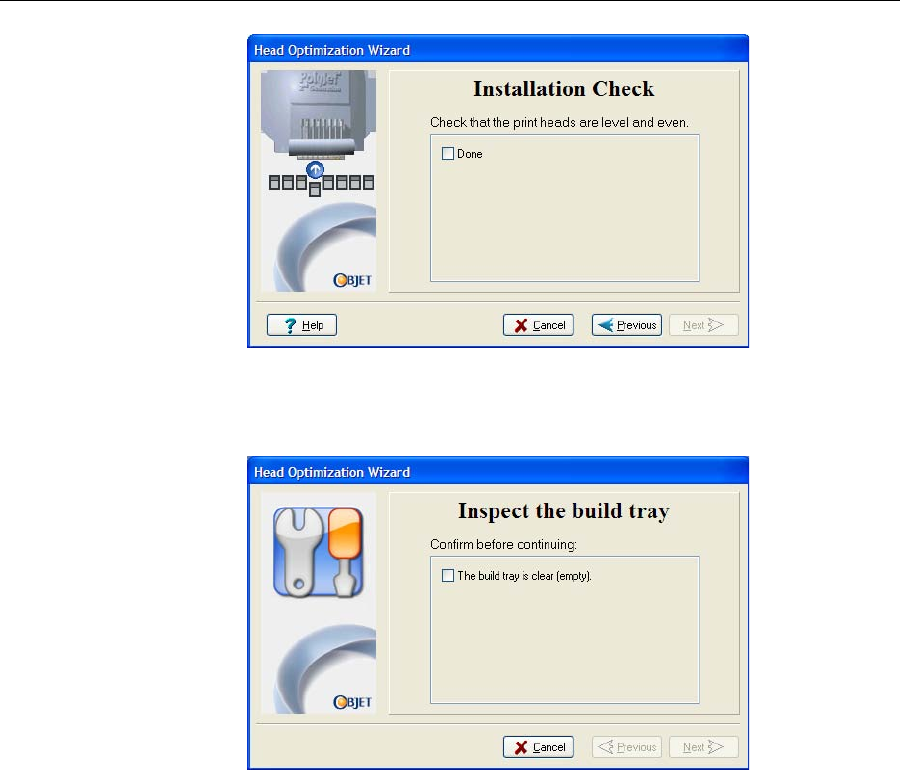
20. Confirmthattheheadsarelevelandevenbyselectingthecheckboxin
thefollowingwizardscreen,andclickNext.
Operating & Maintaining the Connex500/350 3-D Printer
7–46
DOC-13000 Rev. E
Figure 7-70: Installation-check screen
21. Inthenextwizardscreen,selectthecheckboxtoconfirmthatyouhave
removedalltoolsandobjectsfromtheprinter.
Figure 7-71: Cleared-tray confirmation screen
22. Closetheprintercover.
Thewizardcontinuesbyfillingtheheads,thenheatingandpurgingthem.
Iftherearenoinstallationproblems,theHeadOptimizationprocedure
begins(see“CalibratingPrintHeads”onpage 7‐34).
Ifavacuumleakageisdetected,orifthereareotherproblems,thewizard
alertsyouandinstructsyouhowtocontinue(see“InstallationProblems,”
below).
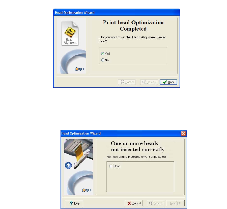
Afterreplacingprintheads,youshouldchecktheheadalignmentbefore
usingtheConnexprintertoproducemodels.Inthefinalwizardscreen...
•selectYesandclickDonetoopentheHeadAlignmentwizard(see
“AligningthePrintHeads”onpage 30).
•selectNoandclickDonetoaligntheheadsatanothertime.
DOC-13000 Rev. E 7–47
Connex500/350 User Guide
Figure 7-72: Final Head Optimization Wizard Screen
Installation
Problems Iftheprinterdetectsthatthereisaproblemafteryouinstallprintheads,
relevantwarningscreensappear.
•Iftheprintersoftwaredoesnotsensethereplacedhead,thefollowing
warningscreenappears.
Figure 7-73: Incorrect-installation screen
Ifthishappens:
a. Opentheprintheadcompartment(seefigure 7‐63onpage 43).
b. Re‐inserttheprint‐headdrivercardintoitssocket(seefigure 7‐67
onpage 44).
c. Inthewizardscreen,selectthecheckboxtoconfirmthatyouhave
re‐insertedthecard,andclickNext.
Operating & Maintaining the Connex500/350 3-D Printer
7–48
DOC-13000 Rev. E
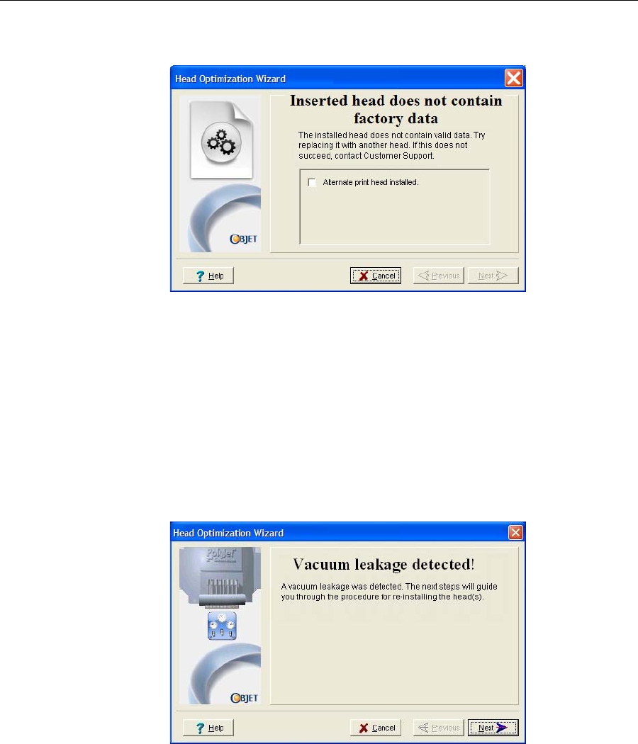
•Ifthereplacementheadwasnotfactory‐calibrated,thefollowing
warningscreenappears.
Figure 7-74: Invalid-data warning screen
Ifthishappens:
a. Removetheheadandreplaceitwithanotherone(startingwithstep
9onpage 7‐42).
b. Inthewizardscreen,selectthecheckboxtoconfirmthatyouhave
installedanotherprinthead,andclickNext.
c. ContactyourauthorizedObjetCustomerSupportcenteraboutthe
unformattedhead.
•Ifthevacuumtestisnotsuccessful,thereplacementheadwasnot
sealedproperlyduringinstallation,andthefollowingwarningscreen
appears.
Figure 7-75: Vacuum Leakage warning screen
Ifthishappens:
a. ClickNext.
b. Followtheinstructionsonthewizardscreenstore‐installthehead.
DOC-13000 Rev. E 7–49
Connex500/350 User Guide
Testing and
Calibrating the
UV Lamps
TheeffectiveradiationoftheUVlampsusedforcuringmodelscanchange
overtime.Toensureoptimumcuringofmodelsduringprinting,apop‐up
messageremindsyoutotestthelampsandcalibratetheireffectiveUV
radiationafterevery200hoursofprinting.YoudothisbyrunningtheUV
CalibrationWizardandusingthebuilt‐inUVradiationsensor.
Thewizardcomparestheradiationyoumeasuretotherecommended
radiationlevelforeachofthelamps,ateachprintingmode—HighSpeed,
HighQualityandDigitalMaterial.Theradiationlevelisconsidered
acceptableifitiswithinsevenpercentoftherecommendedlevel.
Whencalibratingthelamps,thewizardattemptstoadjusttheradiation
level,ifnecessary,andthenpromptsyoutotakeanewreading.Ifthelevel
isacceptable,thewizardcontinuestothenextphase.Iffurtheradjustment
isnecessary,thecurrentphaseisrepeated.Ifthelevelistoolowtobe
adjusted,thewizardcontinuestothenextphase;thefinalwizardscreen
indicatesthatthelamp’sradiationfortheprintingmodeisunacceptable.
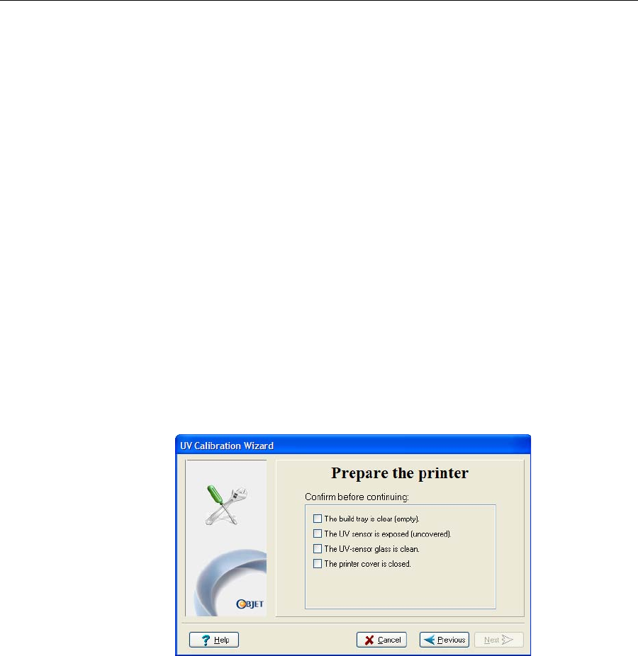
To test and calibrate UV lamp radiation:
1. StarttheUVCalibrationwizardfromtheOptionsmenu(seefigure 7‐26
onpage 23).
2. Makesurethatthebuildtrayisempty,theUVsensorisexposedand
clean,andthattheprintercoverisclosed.Confirmthisinthewizard
screenandclickNext.
Figure 7-76: Confirmation screen
TheUVlampspowerupandstabilize;thistakesseveralminutes.Then,
theprintblockpassesoverthesensor.
Thewizardcomparesthemeasuredradiationtotherecommended
levelforthelampandprintingmodetested,anddisplaystheresult.
Thewizardcontinuesasfollows:
•Ifthelevelmeasuredintheprevioustestisacceptable,thewizard
beginstestingtheleftUVlamp.
•Ifthelevelmeasuredintheprevioustestisnotacceptable,the
wizardcalibratestherightUVlampbyadjustingthecurrent
suppliedtoit,thentestsitagain.
•Ifthelevelmeasuredintheprevioustestistoolowtobeadjusted,
thewizardrecordsthelamp’sradiationasunacceptable,andbegins
testingtheleftUVlamp.
Operating & Maintaining the Connex500/350 3-D Printer
7–50
DOC-13000 Rev. E
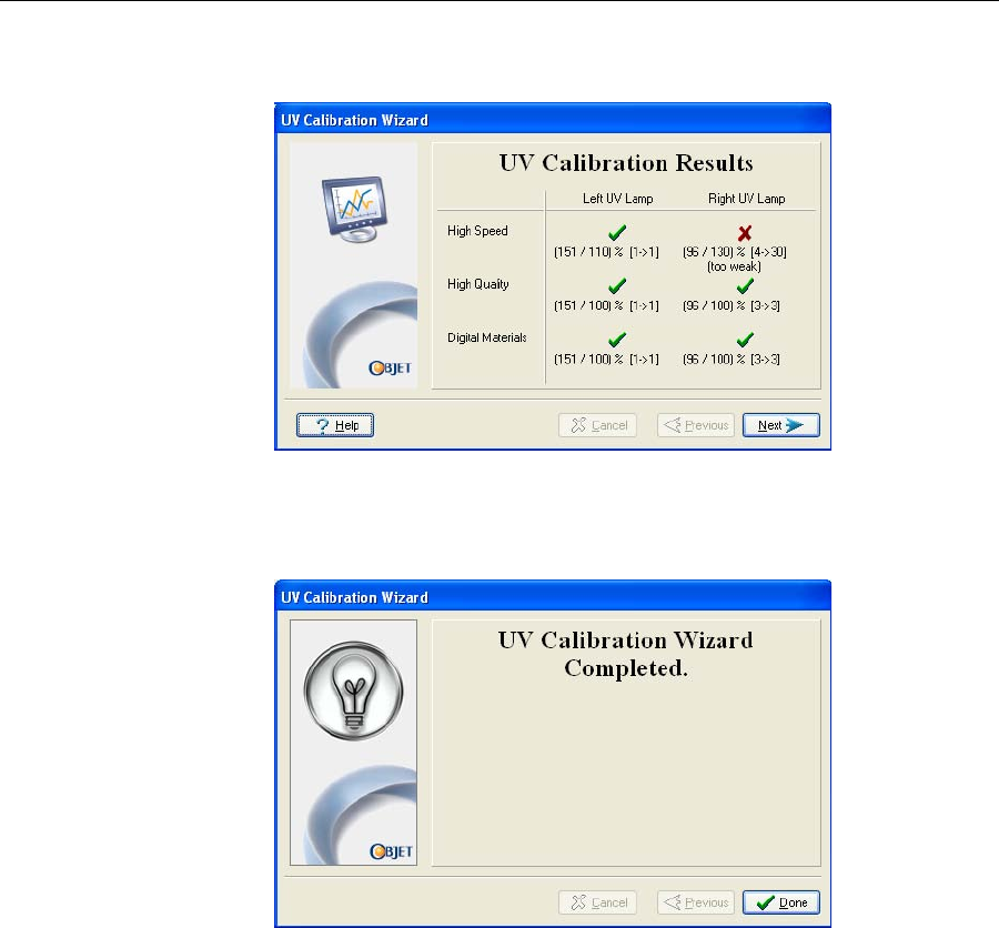
Whenalltesthavefinished,theresultsaredisplayed.Thisshowsthe
currentconditionofthelamps,afterthewizardhascalibratedthem.
Figure 7-77: Results and current condition of the UV lamps
3. CovertheUVsensor,andconfirmthisinthenextscreen.
4. Inthefinalwizardscreen,clickDone.
Figure 7-78: Final UV Calibration Wizard screen
DOC-13000 Rev. E 7–51
Connex500/350 User Guide
Calibrating the
Load Cells Loadcellsaresensorsthatmeasuretheweightoftheprintingcartridges
andthewastecontainerintheprinter.Itisimportantthatyouperiodically
checkthattheweightmeasurementsareaccurate,bothforconvenienceand
topreventunnecessarywasteofprintingmaterials.Itisrecommendedthat
youcalibratetheloadcellsonceamonth,withtheLoadCellCalibration
wizard.
To calibrate load cells:
1. StarttheLoadCellCalibrationwizard.
•FromtheOptionsmenuoftheprinterinterface(seefigure 7‐26on
page 23),selectWizards > Load Cell Calibration.
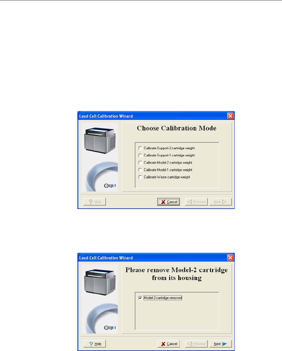
2. Selectoneormoreloadcellsthatyouwanttocalibrate,andclickNext.
Figure 7-79: Load cell selection
Note: It is recommended that you routinely calibrate all of the load cells.
3. Removethecartridgeorcontainer,asinstructedbythewizard,
confirmthisinthewizardscreen,andclickNext.
Figure 7-80: Confirmation of cartridge removal
Operating & Maintaining the Connex500/350 3-D Printer
7–52
DOC-13000 Rev. E
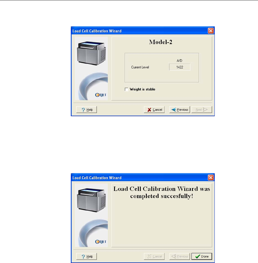
4. Inthenextwizardscreen,observethenumbersandwaituntilthelevel
isrelativelystable—twounitsaboveorbelowtheaveragelevelshown.
Figure 7-81: Load cell calibration screen
5. SelecttheWeightisstablecheckbox,andclickNext.
Ifyouneedtocalibratemorethanoneloadcell,thenextcalibration
screenappears.Repeatsteps4and5untilalloftheloadcellsare
calibrated.
6. ClickDoneinthefinalwizardscreen.
Figure 7-82: Final wizard screen
Replacing the
Odor Filter TheConnex500/350printerhasanactivated‐carbonfilterforremoving
odorsfromprintingmaterials.Thefiltershouldbereplacedregularly
(aboutonceayear,asnecessary)tokeepyourworkingenvironment
pleasant.Thisisnormallydoneduringtheyearlypreventive‐maintenance
servicevisit.
Replacing the
UV Lamps TheUVlampsusedforcuringmodelshavealong,butlimited,working
life.TheObjetserviceengineerteststheireffectivenessduringregular
maintenancechecks,andreplacesthem,ifnecessary.Youcantestand
DOC-13000 Rev. E 7–53
Connex500/350 User Guide
adjusttheireffectivepowerwiththeUVCalibrationWizard(see“Testing
andCalibratingtheUVLamps”onpage 49.IfyouneedtoreplaceaUV
lamp,followtheseinstructions:
1. MakesuretheConnexprinterisinofflinemode.
Figure 7-83: Offline mode indicator (red)
Theonline/offlinebuttonatthebottomoftheprinterinterfaceshouldbe
red.Ifnot,clickittoswitchtheprintertoofflinemode.
2. StarttheUVLampReplacementwizard.
FromtheOptionsmenuoftheprinterinterface(seefigure 7‐26on
page 23),selectWizards > UV Lamp Replacement.
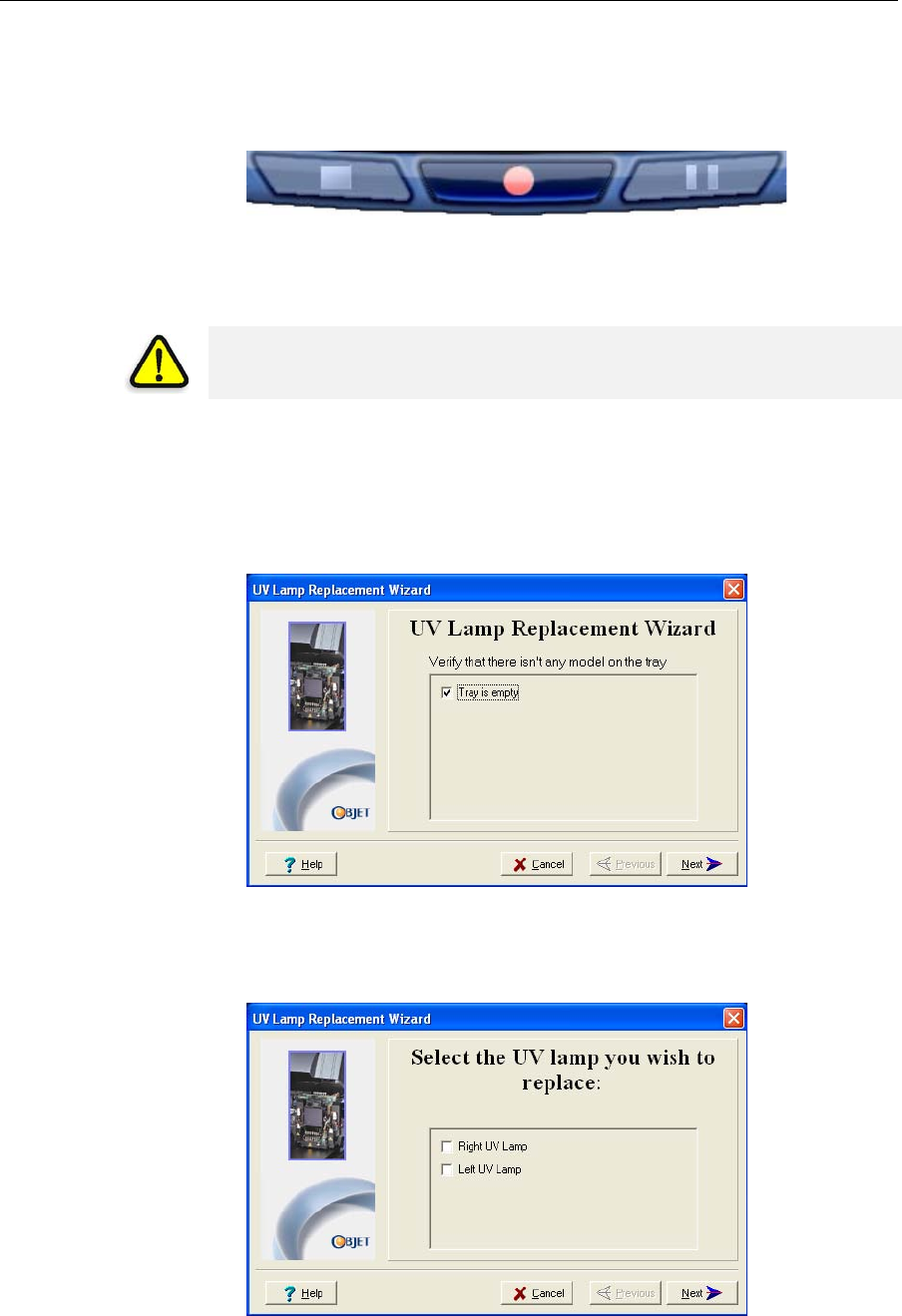
3. Makesurethatthebuildtrayisempty,andconfirmthisinthewizard
screen.Then,closetheprintercoverandclickNext.
Figure 7-84: “Empty tray” confirmation screen
Theaxesmovetothe“home”position.
4. SelecttheUVlamp(s)tobereplacedandclickNext.
Figure 7-85: UV lamp selection screen
WARNING: Before continuing, make sure that the safety interlock in the
printer cover is not defeated, and that the lamp is not hot.
Operating & Maintaining the Connex500/350 3-D Printer
7–54
DOC-13000 Rev. E
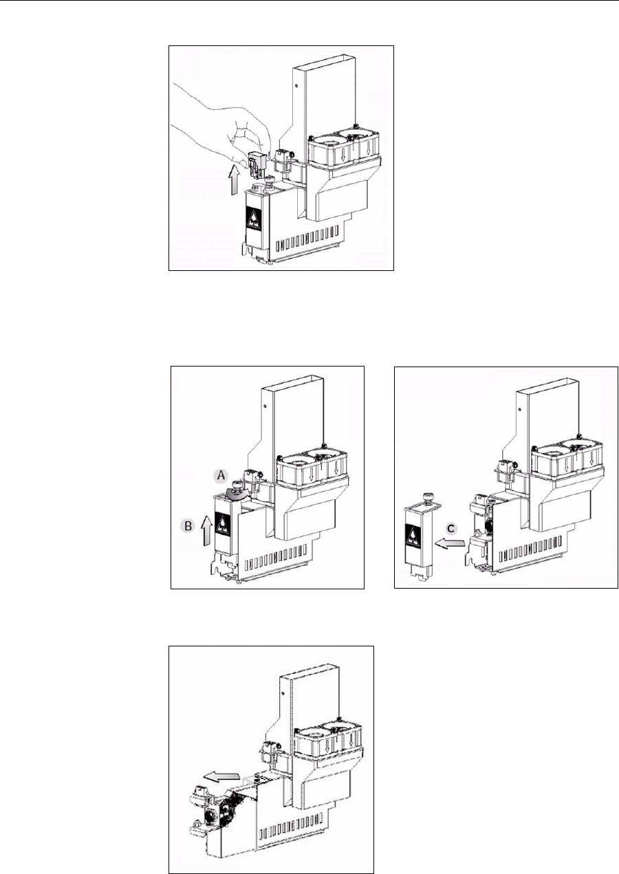
5. DisconnectthepowerconnectiontotheUVlamp.
Figure 7-86: Disconnecting the UV lamp
Note: Do not disconnect the power connection to the cooling fans.
6. LoosenthescrewsecuringtheUVlampcover(A),andpullthecover
up(B),thenout(C).
Figure 7-87: Removing the UV lamp cover
7. Pullthelampreflectoroutoftheprintblock.
Figure 7-88: Removing the UV lamp reflector
DOC-13000 Rev. E 7–55
Connex500/350 User Guide
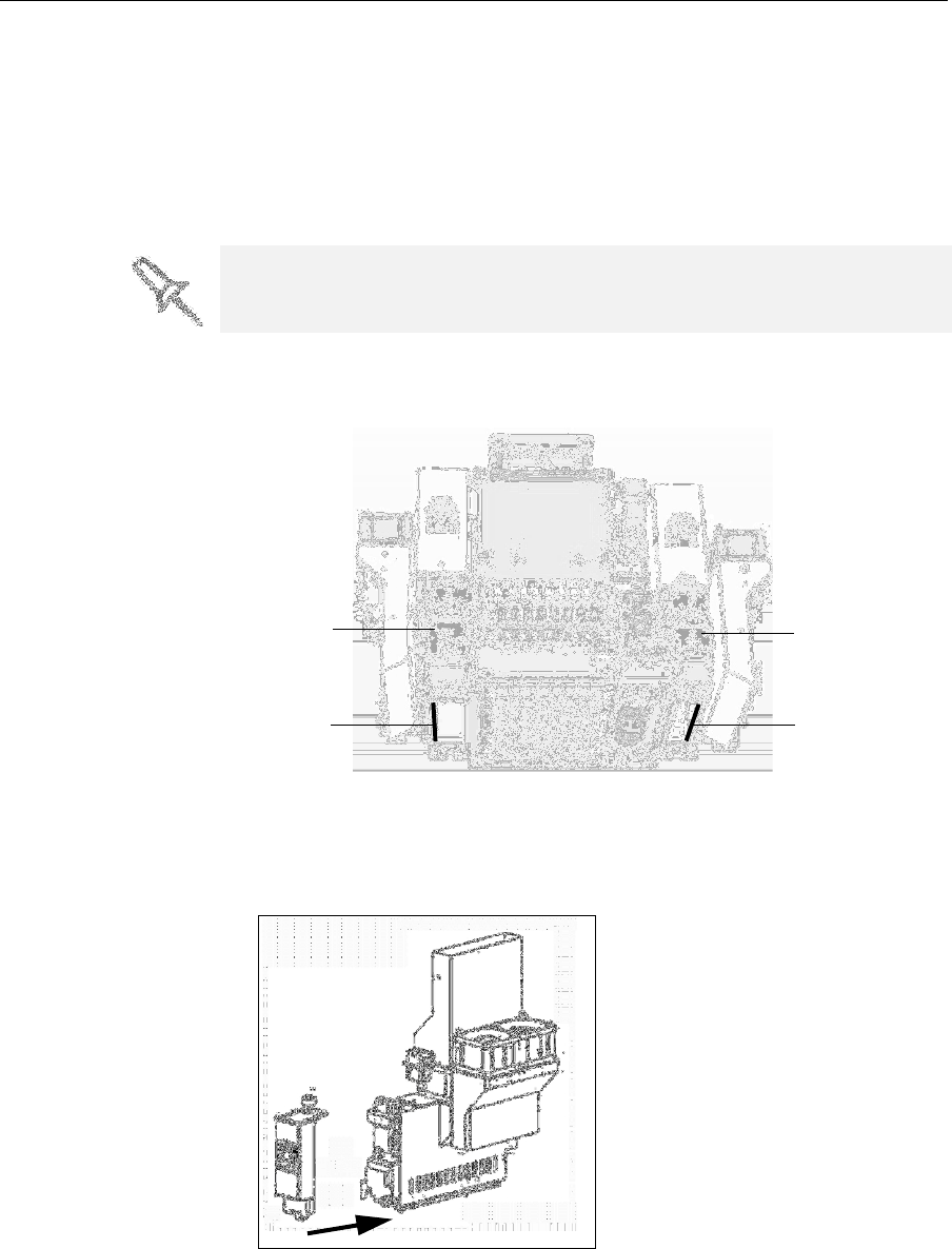
8. Inspectthenewlampreflector,andmakesurethatablackstripis
attachedtotheinsideofit.Ifnot,installone—onthesideofthe
reflectoropposite(notnextto)theprintblock.
Note: Extra black strips are included in the printer Start-up Kit. If
necessary, you can remove the black strip from the old reflector and install
it in the new reflector (as long as the black paint has not faded).
9. Discardtheoldreflectorandlamp.
10. InsertthenewUVlamp/reflectorunitintothehousingnexttotheprint
block.
Figure 7-89: Print block and UV lamp assembly, showing correct placement of
black strip
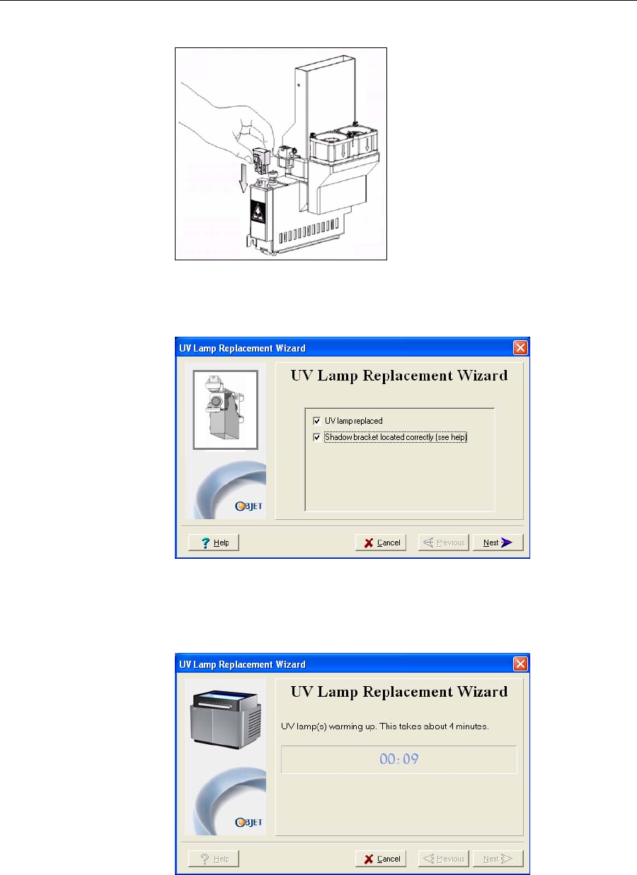
11. Replacethelampcoverbyinsertingitintotheslotonthebottomofthe
housing,andtightenthesecuringscrewontop.
Figure 7-90: Replacing the lamp cover
Dispose of the used UV lamp in accordance with environmental and safety
requirements.
Black strip
UV lamp
assembly
Black strip
UV lamp
assembly
Operating & Maintaining the Connex500/350 3-D Printer
7–56
DOC-13000 Rev. E
12. ReconnectthepowerconnectiontotheUVlamp.
Figure 7-91: Connecting power to the UV lamp
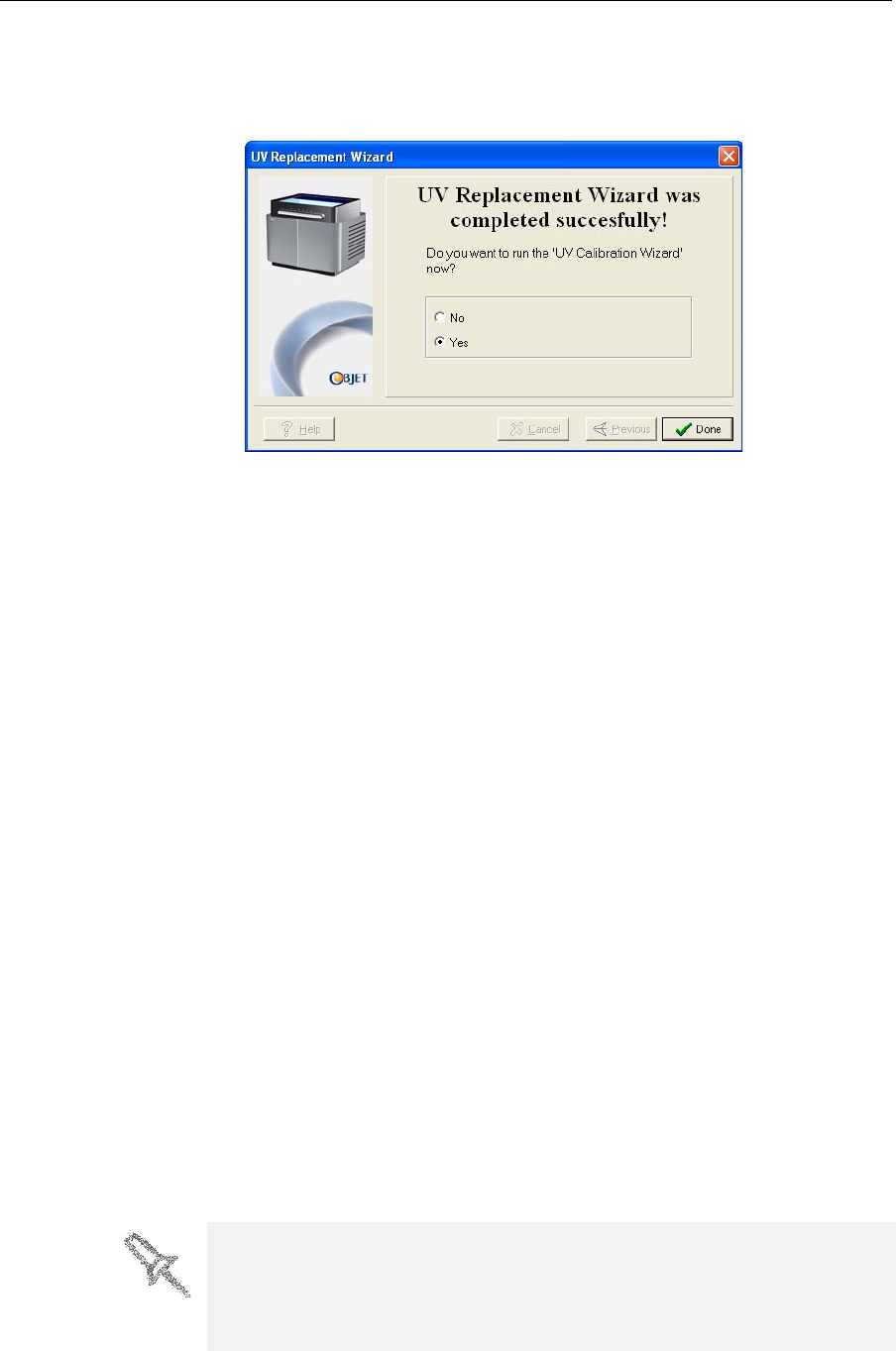
13. Inthewizardscreen,confirmthatyouhavereplacedthelamp(s)and
thattheblackstripisattached,thenclickNext.
Figure 7-92: UV-installation confirmation screen
Thewizardoperatesthelampsandchecksiftheirpoweriswithinthe
acceptablerangeforeachprintingmode.(Themodecurrentlybeing
checkedappearsinthelower‐leftcorneroftheprinterinterface.)
Figure 7-93: Status screen during UV lamp check
DOC-13000 Rev. E 7–57
Connex500/350 User Guide
14. AfterreplacingaUVlamp,itisrecommendedthatyoucalibrateits
powerforthevariousprintingmodes.Thefinalscreenallowsyouto
continuetotheUVCalibrationwizard(see“TestingandCalibrating
theUVLamps”onpage 7‐49).
Figure 7-94: Final wizard screen
Built-in Tests ThesoftwarethatrunsyourConnexprintercontainsasuiteoftestsfor
regularlycheckingthehardwareandsoftware,andfortroubleshooting.
Youcanconfigurebasiccommunicationsandenvironmentteststorun
automatically,whentheConnexsoftwareopens.Inaddition,youcanruna
morecomprehensivesetoftestsbeforeprocessingaprintjob,asasystem
check,toensureoptimumprintingresults.
Becauserunningthetestseffectstheoperationoftheprinter,youcanonly
opentheBuilt‐inTestsinterfacewhentheConnexsystemisnotprinting.
Thetestsuitefeatures:
•Theorganizationofprinting‐relatedtasksincategories:
Communications
Datacards
Temperatures
Voltages
Encoderrepeatability
Print‐headheating
Print‐headfilling
•Acleardisplayoftestresultsandthesourceofanyfailures,enabling
youtodetermineifprintingispossibleorworthwhile.
•Theabilitytomonitortestresultsforspecificcomponents.
•Troubleshootingtips.
Runningthesetestscanhelpidentifyproblemsintheprinterhardwareand
software.Alargenumberofhardwaredefects(ornear‐defects)warnsyou
ofpossibleprintingproblems,eitherforcurrentorfuturejobs.
Objet recommends running the built-in tests in the following cases:
•as a routine test, once every two weeks
•as a system check, before major (long) jobs
•as needed, for troubleshooting
Operating & Maintaining the Connex500/350 3-D Printer
7–58
DOC-13000 Rev. E
Accessing
Built-in Tests To open the Built-in Tests screen, do one of the following:
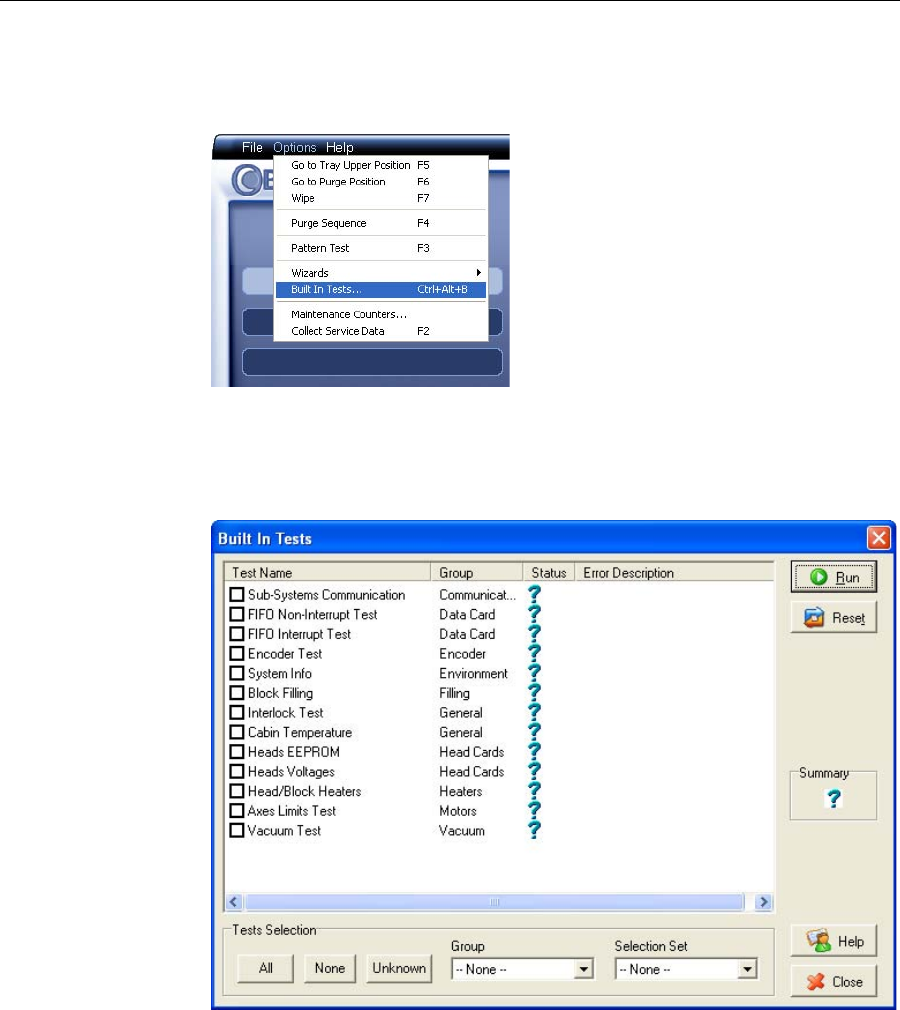
•FromtheOptionsmenu,selectBuilt-In Tests.
•PressCtrl+Alt+B.
Figure 7-95: Selecting Built-In Tests from the Options Menu
Test Interface TheBuiltInTestsscreenlistspre‐configuredtests,groupedbycomponent
categories.Inthisscreen,youselectandruntests,andtheresultsare
displayed.
Figure 7-96:Built In Tests screen
Test List TestName
Thiscolumnlistsallofthetests,togetherwithselectioncheckboxes.
Clickthecheckboxestoselectthetestsyouwanttorun.Toremovea
selection,clickthecheckboxagain.Toquicklyselectallofthetestsina
componentcategory,usetheGrouppull‐downmenuatthebottomofthe
screen.
Group
Thiscolumnshowsthecomponentcategoriesforeachtest.
ThistellsyouwhichtestsarerunwhenselectingacategoryfromtheGroup
pull‐downmenuatthebottomofthescreen.
DOC-13000 Rev. E 7–59
Connex500/350 User Guide
Status
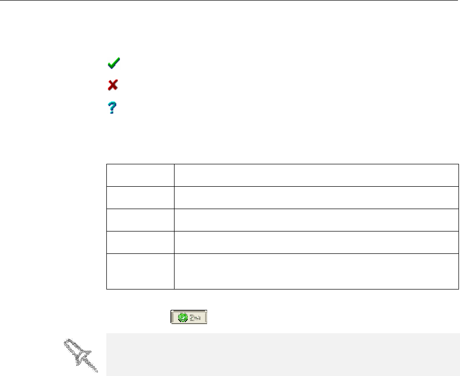
Thiscolumnshowsthestatusofeachtestafteryourunit:
Test Selection Area IntheTestSelectionarea,atthebottomofthescreen,youcanquicklyselect
orde‐selecttestsbytheircharacteristics:
Running Tests To run the selected tests:
¾ClickRun.
Testsuccessfullycompleted.
Testfailed.
Unknownresults.(Thetesthasnotbeenrunyet.)
All Clicktoselectallofthetestsinthelist.
None Clicktode‐selectallofthetestsinthelist.
Unknown Clicktoselectalltestthathavenotbeenrunyet(Status = ?).
Group Usethismenutoselecttestsbycomponentcategory.
Selection
Set
Usethismenutoselectapre‐configuredsetofteststorunat
specifiedtimes(computerstartup,beforeprinting,etc.).
After you run a test, the Save and View command buttons are added to the
Operating & Maintaining the Connex500/350 3-D Printer
7–60
DOC-13000 Rev. E
Test Results To save and view a report of all of the tests:
¾UsetheSaveandViewcommandbuttons(seebelow).
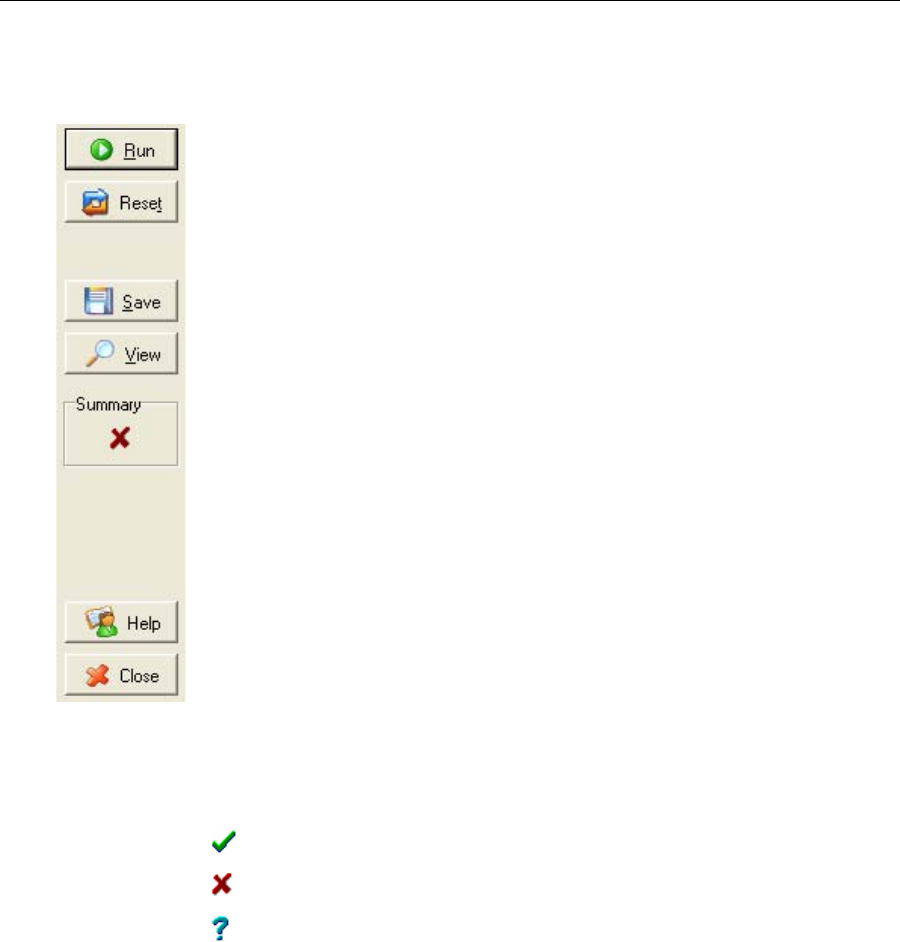
Command Buttons Youclickthecommandbuttons,ontherightsideofthescreen,toperform
thefollowingoperations:
Run
Clicktoruntheselectedtests.
Reset
Clicktoclearpreviouslyruntests.Thisreturnsthestatusofeachtestto
Unknown(?).
Save
Clicktosaveareportthatsummarizesthetestsrun.Thereportissavedas
anHTMLfile.Youcansaveanynumberofreportsforthetestsyourun;the
nameofthefilesavedisBITReport [date][time].htm.Bydefault,thesefiles
aresavedintheConnexinstallationfolder,butyoucansaveitinanyother
folder.
View
Clicktodisplaythelatesttestreportthatyousaved.(Youcanviewother
testreportsbyopeningtherelevantfilesinyourWebbrowser.Todoso,
openWindowsExplorer,anddoubleclicktheBITReportfile.)
Close
ClicktoclosetheBuilt‐inTestsscreen.
Summary Ontherightsideofthescreen,asymbolrepresentsthecombinedresultsof
allthetestsrun,usingthesymbolsfromtheStatuscolumn.
Alltestssuccessfullycompleted.
Atleastonetestfailed.
Notalltestsperformed.

DOC-13000 Rev. E 7–61
Connex500/350 User Guide
Test Descriptions
and
Troubleshooting
ThefollowingtableliststhenameofeachtestintheBuilt‐inTestssuite,
togetherwithitsdescriptionandapossiblereasonforitsfailure.Ifyou
needassistance,contactyourObjetserviceprovider.
Test Name Description Possible Reason for Failure
Sub‐System
Communication Testscommunicationsbetween
Edencomponents. Disconnectedcommunicationscable.
Faultycable.
FIFONon‐Interrupt/
FIFOInterrupt
TeststhedataqueueintheDATA
PCIcard. FaultyDATA_PCIcard.
Encoder Teststheencoderʹsreliabilityby
comparingreadingsfrommultiple
runsalongtheX‐axis.
Faultyencoder.
SystemInfo Comparesthefollowingparameter
valueswiththeminimum
requirements.
•Physicalmemory
•Availablememory
• Freespaceondisk
•Monitorresolution
FailureofRAMmemoryallocationin
theEdencomputer.
BlockFilling Analyzesthethermistorreadings
whentheblockisfullandwhenitis
empty.
Faultythermistor.
Interlock Teststheinterlockintheprinter
cover. Failureofinterlockmechanism.
Faultylatch.
Disconnectedcables.
CabinTemperature Teststhetemperaturelevelinthe
build‐trayarea. Faultytemperaturesensor(OHDB).
HeadEEPROM Teststheread/writecapabilitiesof
theprint‐headdrivercards. Faultyprint‐headdrivercard.
HeadVoltage Checksthecontrolofvoltages
suppliedtotheprintheads. Faultyprint‐headdrivercard.
TrayHeater Notusedforthisprinter —
Head/BlockHeaters Teststheheatersintheprintheads
andintheprint‐blockbody. Faultyheatersorthermistors.
AxesLimit Teststhehardwareandsoftware
limitsofallaxes. Faultyhardwaresensors.
WrongMaxPositionparameter.
Vacuum Teststhevacuumlevelintheprint
block. Faultyvacuumsensor.
Vacuumleakage.
Wrongparameters.
Operating & Maintaining the Connex500/350 3-D Printer
7–62
DOC-13000 Rev. E
Replacing the
Waste
Container
Thewastecontainercontainspartiallycuredpolymericmaterialproduced
duringnormaloperationandmaintenanceoftheConnexprinter.Forsafety
andenvironmentalreasons,thismaterialiskeptinaspecialleak‐proof,
disposablecontainer.
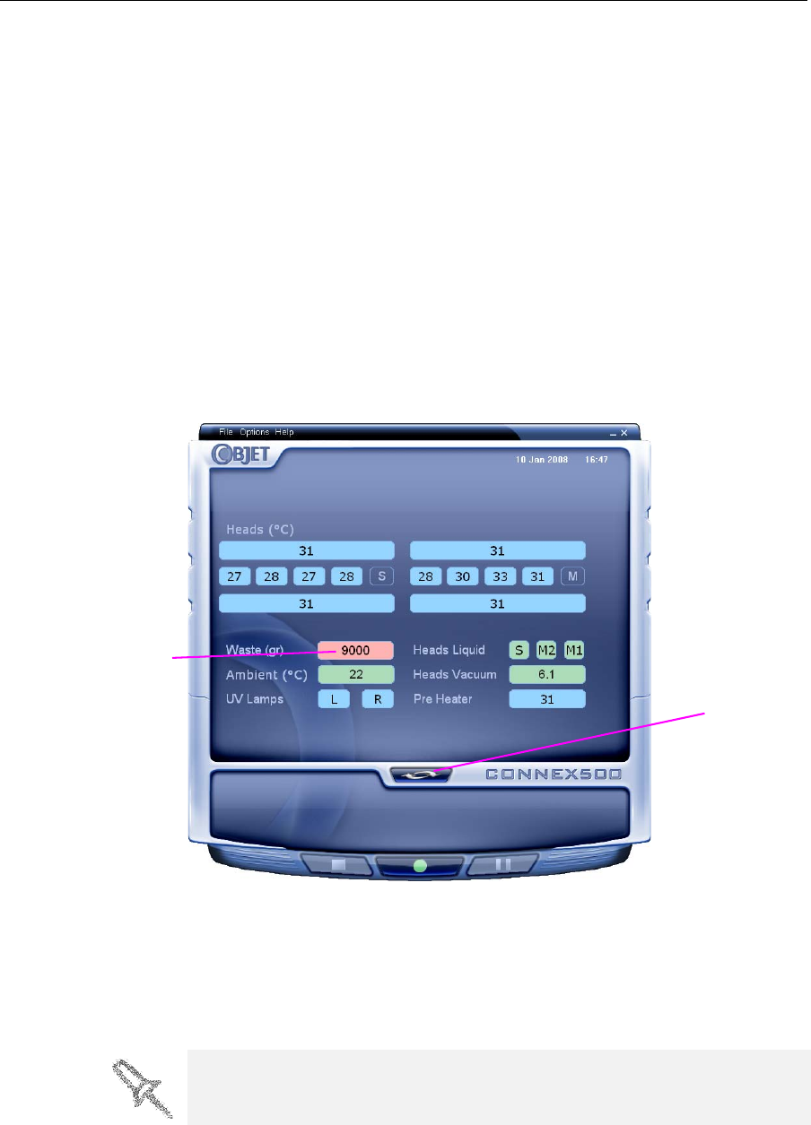
Thecontainerhasacapacityof10kilogramsofwastematerial—usually
enoughforseveralmonthsofprinteruse.Theprintersoftwaredisplaysa
warningmessagewhenthereis9kilogramsofmaterialinthecontainer,
andstopstheprinterwhenthenetweightreaches9.5kilograms.Above9
kilograms,thesoftwaredoesnotallowyoutostartaprintjob(oraprinting
activity)untilyoureplacethewastecontainer.Youcanmonitortheweight
ofthewastecontainerintheMaintenancescreenoftheprinterinterface.You
canalsovisuallyinspectthelevelofwasteinthecontainer.(Toaccessit,see
page 7‐63.)
To monitor the waste weight (and other indicators) in the Connex printer:
¾Inthemainprinterinterfacescreen,clickthedisplaytoggletoviewthe
Connexprinterindicators.
Figure 7-97: Connex printer interface, showing waste weight (red background
indicates operator alert)
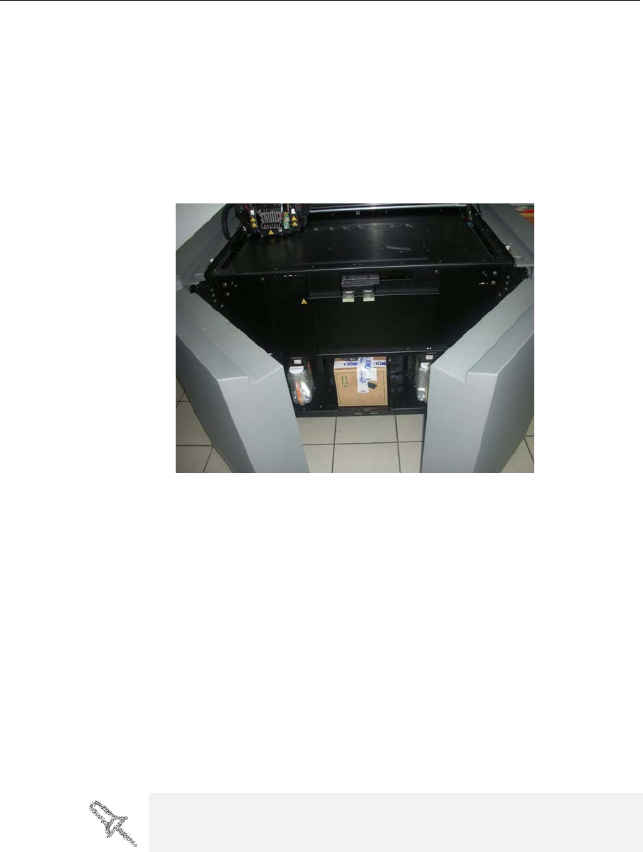
Thewastecontainerconsistsofaplasticcontainerinsideacardboardbox.
Youtypicallydisposeoftheentirewastecontainer—includingthebox.
Therefore,youmustassembleanewboxandinsertanewplasticcontainer
beforeyoucaninstallitintheprinter.
Waste weight
Display
toggle button
Replacement boxes, plastic containers, and sealing caps are supplied in the
Connex printer start-up kit and in the preventive-maintenance kit.
DOC-13000 Rev. E 7–63
Connex500/350 User Guide
To prepare a new waste container:
1. Assemblethecardboardbox,makingsuretopunchouttheperforated
sections.
2. Placeanewplasticcontainerintothebox.
Note: Do not close the box until you connect the waste drain tube from the
printer (see below).
To replace the waste container:
1. Openthefrontdoorsoftheprinter.
Figure 7-98: Accessing the waste container
2. Carefullyslideoutthewastecontainertoremoveitfromtheprinter.
3. Placethenewwastecontainernexttothefullcontainer.
4. Unscrewthecapsecuringthewastedraintubeandconnectittothe
newcontainer.
5. Closethefullcontainerwithasealingcap.
6. Closethenewwaste‐containerbox,usingtapetoholditclosed.
7. PositionthewastecontainerundertheConnexprinter,ontheload
cells.
•Thecontainershouldbeontheextremerightsideofthe
compartment.
•Makesurethatthewastedraintubeisnotcrimpedandthatitisnot
pinchedbythecontainer.
8. Closethewastecompartmentdoor.
Dispose of the full waste container in accordance with environmental and
safety requirements.

Operating & Maintaining the Connex500/350 3-D Printer
7–64
DOC-13000 Rev. E
Cleaning the
Exterior Panels ThepaintedexteriorplasticpanelsofConnex3‐Dprintershaveadurable
finish,offeringexcellentchemicalresistancetocommoncleaningagents.
However,followtherecommendationsbelowwhencleaningtheseareasof
theprinter.
AcceptableCleaningAgents
•mildsoapsolution
•commonhouseholdcleanersandwindowcleaners
•commoncommercialandindustrialdetergents,5%solutioninwater
•alcohol(ethanol,isopropanol),10%to40%solutioninwater
Wipetheexterioroftheprinter,usingasoftclothmoistenedwiththe
cleaningsolution.
UnacceptableMaterials
•industrialsolvents
•cleaningagentscontaininghydrocarbons,ketones,estersandlacquer
thinners
•spraydisinfectants
•abrasivesandagentswhichcouldwearawaythepanelfinish

DOC-13000 Rev. E 8–1
Handling Printed Models
RemovingModelsAfterPrinting...................................................... 2
RemovingtheSupportMaterial........................................................ 2
StoringModels..................................................................................... 3

Handling Printed Models
8–2
DOC-13000 Rev. E
Removing Models After Printing
Afterprintingmodels,youshouldallowthemtocoolasmuchaspossible
beforehandlingthem.Ifadditionalmodelsdonothavetobeproducedon
theConnexprinter,itisbesttolettheprintedmodelscoolintheprinter,
withthecoverclosed,aslongaspossible.
If the Connex printer must be used to produce additional models as
soon as possible:
1. Lettheprintedmodelscoolonthebuildtrayforatleast10minutes.
2. Verycarefully,removethemodelsfromthetraywithascraperor
spatula(suppliedinthetoolkit),takingcarenottopryorbendthe
model.
3. Placethemodelsonaflatsurface,andcoverthemwithacardboard
boxorpaperhood.
Thisallowsthemodelstocoolslowlyandevenly.
4. Letthemodelscoolforseveralhours.
Removing the Support Material
Afterprintedmodelshavecooled,thesupportmaterialmustberemoved.
Thiscanbedonebydifferentmethods,dependingonthesizeofthemodel,
howdelicateitis,theamountandlocationofthesupportmaterial,and
otherfactors.Usethefollowingmethodsasaguide,andadaptthem(ora
combinationofthem)forfinishingthemodelsyouarehandling.
Removing Excess Support Material by Hand
Whilewearingprotectivegloves,breakawayexcesssupportmaterialon
theoutsideofthemodel.Fordelicatemodels,useatoothpick,pinorsmall
brushafterdippingthemodelinwater.
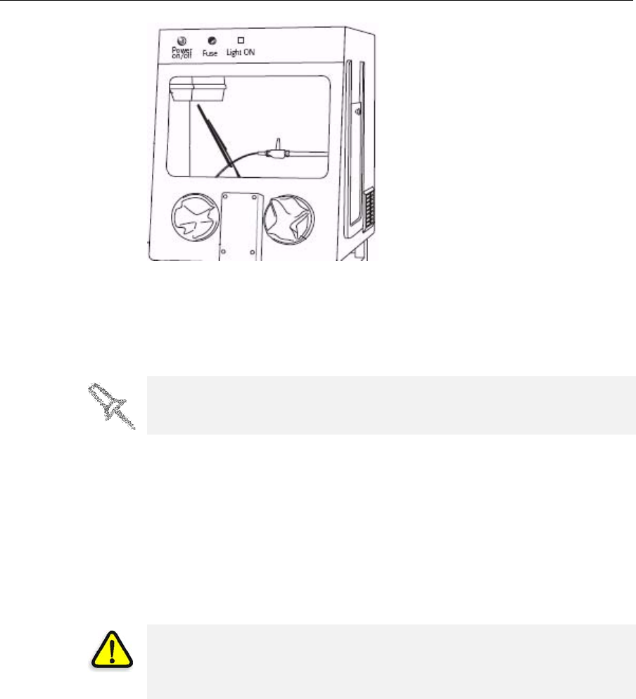
Removing Support Material with Water Pressure
Formostmodels,themostefficientwaytoremovesupportmaterialisby
usingahigh‐pressurewaterjet.OnesuitablesystemistheBalcoWaterJet
cleaningunit,showninfigure 8‐1onpage 8‐3.Thisdeviceismarketedby
Objet.
WARNING: Wear protective gloves when handling printed models
before they are washed.
DOC-13000 Rev. E 8–3
Connex500/350 User Guide
Figure 8-1: Balco WaterJet Cleaning Unit
Tocleanamodelusingthisdevice,youplaceitinthechamber,andyou
manipulateitandthejetusingthebuilt‐in,waterproofsleeves.Apump
turnsordinarytapwaterintoahigh‐pressurejet,andawiperkeepsthe
windowclear.
Removing Support Material with Caustic Soda
Soakmodelsina2‐percentsolutionofcausticsoda(sodiumhydroxide)to
removesupportmaterialfromdifficult‐to‐reachareasandtogivethe
modelasmooth,cleanfinish.Theamountoftimeyousoakthemodelinthe
solutiondependsonhowdelicateitisandhowmuchsupportmaterial
needstoberemoved,butitistypicallybetweenhalf‐an‐hourandseveral
hours.Inanycase,youshouldremoveasmuchsupportmaterialas
possiblebeforethecausticsodatreatment,andrinsethemodelthoroughly
(withawaterjet)afterwards.
Storing Models
Modelsarecuredastheyareprinted,makingthemsafeandstablefora
longtime.However,properstorageconditionsarenecessarytoprevent
deforming.
•Keepprintedmodelsatroomtemperatureandinalow‐humidity
environment.
•Donotexposemodelstodirectsunlightandotherheatsources.
Use caution when cleaning delicate models with high-pressure water
systems.
WARNING: Caustic soda may cause chemical burns, scarring and
blindness. Mixing it with water generates heat that could ignite other
materials.Take adequate safety precautions; always use nitrile gloves
when handling caustic soda and models soaked in it.

Handling Printed Models
8–4
DOC-13000 Rev. E