Strategic Technologies STISURETRAC User Manual PART 1
Strategic Technologies Inc. PART 1
Contents
- 1. USER MANUAL PART 1
- 2. user manual part 2
- 3. user manual part 3
- 4. user manual part 4
USER MANUAL PART 1

STRATEGIC Technologies Inc.
Ref. Doc. No. R.D.5.3.1I Rev 0.1 Jan 18/1999 Page 1
SPECIAL NOTE :
This Users Guide is for use with v2.1 of the PRU+ Firmware. See PRU+ Basics on Page
9 for information regarding how to determine the PRU+ Firmware version. Different versions
of the PRU+ software may not have the same features described in this manual and / or may
function differently than this manual states.
FCC STATEMENT:
This device complies with Part 15 of the FCC rules. Operation is subject to conditions:
(1) This device may not cause harmful interference, and (2) this device must accept interference
received, including interference that may cause undesired operation.
Changes or modifications not expressly approved by STRATEGIC Technologies Inc.
invalidate any approval or warranty applying to the product and can void the user’s authority to
operate this equipment.

STRATEGIC Technologies Inc.
Ref. Doc. No. R.D.5.3.1I Rev 0.1 Jan 18/1999 Page 2
Platinum Plus New Features and Enhancements
Quick Install Mode
This new feature makes installation of the PRU+ quicker and more convenient. The visual display
screen on the front of the PRU+ will prompt the installer for each step and guide them through the
installation process. For a more detailed description, see page 44.
Domestic Violence Deterrent System - more detailed support
The PRU+ now has more detailed support for Strategic’s Domestic Violence Deterrent system. The
Domestic Violence Deterrent System is designed to provide curfew monitoring for both the offender and
the victim. The PRU+ contains a specific setting for the transmitter, in the form of a pendant, which is
worn by the victim. This enables the PRU+ to determine if the offender, wearing a transmitter, entered
the victim’s area or if the pendant transmitter was activated by the victim. There is also support for an
optional panic button that enables the victim to send a panic message to the monitoring center. For
a more detailed description, see page 32.
Tone Dialling
The PRU+ now supports both styles of dialling (tone and pulse). For further details see page 36.
A more convenient method to set a Dial Prefix
In some situations (ie: hotels and offices)., a dial prefix may be required to enable the PRU+ to dial from
that location. An extra digit, such as “9", can be added without necessitating a change of the entire
number to be dialled. For a more detailed description, see page 38.
Motion Sensor
The PRU+ now has the ability to determine if it is being moved. See page ? For more details.
Automatic saving of changes
All changes to any programmed settings are now automatically saved when they are edited.

STRATEGIC Technologies Inc.
Ref. Doc. No. R.D.5.3.1I Rev 0.1 Jan 18/1999 Page 3
Table Of Contents
PRU+ Overview............................................................................................................................Page 6
Required field equipment for installing and/or removing a unit .......................................Page 6
PRU+ Basics ................................................................................................................................Page 7
Turning the PRU+ on .......................................................................................................Page 7
Turning the PRU+ off .......................................................................................................Page 7
Figure 2 : Front Panel Display......................................................Page 7
PRU+ Indicator Lights and Buttons..................................................................................Page 8
PRU+ Operation (Run Mode)...........................................................................................Page 8
PRU+ Calling the Central Computer................................................................................Page 9
Call Attempt Error Messages ...............................................................................Page 9
Blind Dial Mode ..................................................................................................Page 10
PID Basics..................................................................................................................................Page 11
Features .........................................................................................................................Page 11
Resetting the PID ...........................................................................................................Page 11
Figure 2 : Resetting a PID..........................................................Page 11
LOCK Basics ..............................................................................................................................Page 12
Replacing the Battery.....................................................................................................Page 12
FVU Basics.................................................................................................................................Page 13
Setting up the FVU .........................................................................................................Page 14
Setting the date and time ...............................................................................................Page 14
CMU Basics................................................................................................................................Page 15
Installation ......................................................................................................................Page 15
Removal .........................................................................................................................Page 15
PRU+ Installation Procedures...................................................................................................Page 16
Active Mode Installation ............................................................................................................Page 17
Pre-Installation................................................................................................................Page 17
PRU+ Installation - Quick Install ...................................................................................Page 17
PID Installation ...................................................................................................Page 18
Figure 3: Installing the battery in the PID...................................Page 18
Figure 4 : Strap Installation ........................................................Page 18
Figure 5 : Attach the PID to the baseplate.................................Page 19
Figure 6 : Slider Bar ...................................................................Page 19
Installation Completion.......................................................................................Page 19
PRU Installation - Classic...............................................................................................Page 20
PID Installation ...................................................................................................Page 20
Figure 3: Installing the battery in the PID...................................Page 20
Figure 4 : Strap Installation ........................................................Page 21
Figure 5 : Attach the PID to the baseplate.................................Page 21
Figure 6 : Slider Bar ...................................................................Page 21
Installation Completion.......................................................................................Page 22

STRATEGIC Technologies Inc.
Ref. Doc. No. R.D.5.3.1I Rev 0.1 Jan 18/1999 Page 4
De-Installation / Removal ...............................................................................................Page 23
Passive Mode.............................................................................................................................Page 24
Important Information Regarding Passive Mode Operation ..........................................Page 24
Passive Mode Installation ..........................................................................................................Page 25
Pre-Installation................................................................................................................Page 25
PRU Installation - Quick Install.......................................................................................Page 25
PID Installation ...................................................................................................Page 25
Figure 3: Installing the battery in the PID...................................Page 26
Figure 4 : Strap Installation ........................................................Page 26
Figure 5 : Attach the PID to the baseplate.................................Page 26
Figure 6 : Slider Bar ...................................................................Page 27
Installation Completion.......................................................................................Page 27
PRU Installation - Classic...............................................................................................Page 27
PID Installation ...................................................................................................Page 28
Figure 3: Installing the battery in the PID...................................Page 28
Figure 4 : Strap Installation ........................................................Page 28
Figure 5 : Attach the PID to the baseplate.................................Page 29
Figure 6 : Slider Bar ...................................................................Page 29
Installation Completion.......................................................................................Page 29
Downloading Information inside the PRU+....................................................................Page 30
De-Installation / Removal ...............................................................................................Page 30
Domestic Violence......................................................................................................................Page 32
Domestic Violence Installation ...................................................................................................Page 33
Pre-Installation................................................................................................................Page 33
PRU+ Installation............................................................................................................Page 33
Check the Participant’s PID ...........................................................................................Page 33
Figure 3 : Test Mode Display .....................................................Page 42
Quick Install................................................................................................................................Page 44
Motion Sensor ............................................................................................................................Page 45
PRU+ / PID Preventive Maintenance.........................................................................................Page 46
Returned PRU+'s ...........................................................................................................Page 46
Physical Checks .................................................................................................Page 46
Figure 7 : Underneath a PRU+ ..................................................Page 46
Electrical Checks................................................................................................Page 47
Figure 8 : Test Mode Display .....................................................Page 47
Returned PID's ...............................................................................................................Page 48
Physical Checks .................................................................................................Page 48
Figure 9 : The Underneath of a PID...........................................Page 48
....................................................................................................Page 48
Electrical Tests...................................................................................................Page 48
Testing a PID..........................................................................................Page 48
Returned Straps ............................................................................................................Page 49
Figure 11 : Strap Cleaning .........................................................Page 49

STRATEGIC Technologies Inc.
Ref. Doc. No. R.D.5.3.1I Rev 0.1 Jan 18/1999 Page 5
Individual Status Log Report......................................................................................................Page 50
Events.............................................................................................................................Page 50
Event Type Definitions ...................................................................................................Page 51
Explanation of the Individual Status Log Report........................................................................Page 53
Frequently Asked Questions......................................................................................................Page 56
Trouble-Shooting........................................................................................................................Page 58
PRU Tips ........................................................................................................................Page 58
PID Tips..........................................................................................................................Page 60
FVU Tips.........................................................................................................................Page 61
LOCK Tips......................................................................................................................Page 61
System Definitions......................................................................................................................Page 62

STRATEGIC Technologies Inc.
Ref. Doc. No. R.D.5.3.1I Rev 0.1 Jan 18/1999 Page 6

STRATEGIC Technologies Inc.
Ref. Doc. No. R.D.5.3.1I Rev 0.1 Jan 18/1999 Page 7

STRATEGIC Technologies Inc.
Ref. Doc. No. R.D.5.3.1I Rev 0.1 Jan 18/1999
PRU Overvie
w
Page 8
PRU+ Overview
Strategic’s Platinum Plus (PRU+) combines ease of use with unequalled flexibility. The features
of the PRU+ have been designed to simplify equipment installation and program management, and to
provide for future expansion and enhancements. The features of the PRU+ include:
Small footprint - 0.4 square feet
Lightweight (4.2 lbs)
Compact, aesthetic design
Removable AC power adapter, with latching connector
Two RJ-11 modular telephone jacks for a line connection and a telephone
15-pin expansion connector
16-character by 2-line visual display panel for displaying configuration settings,
installation instructions, and other information
Two front panel input buttons for user input and changing configuration settings
Internal Antenna
Variable Range (Adjustable)
Y2K Compliant
New Proprietary Signal Processing
Quick Install Mode
Required field equipment for installing and/or removing a unit
To install or remove the PRU+ / PID set, or to use any of the special function mode features, only the
following items are required:
• The PRU+ / PID set complete with strap, locking bar and pin
A Platinum Plus Series LOCK
Scissors
• Small flat head (slotted) screwdriver
STRATEGIC Technologies Inc.
Ref. Doc. No. R.D.5.3.1I Rev 0.1 Jan 18/1999
PRU Basics
Page 9
PRU+ Basics
Turning the PRU+ on
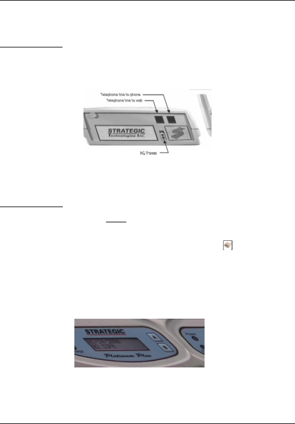
To begin the installation process, the PRU+ must be turned on. To turn the PRU+ on, simply connect
the AC adapter to the back of the PRU+ (See Figure 1 below ) and plug the adapter into a standard wall
outlet. Note: Do not connect the telephone line. The PRU+ will immediately activate, sounding one
or more beeps, and is ready for the next step in
the installation process.
Figure 1 : Back Panel of the PRU+
Turning the PRU+ off
Removing/disconnecting AC power will not turn the PRU+ off. Removal of AC power will cause the
PRU+ to function using its internal battery. The PRU+ will continue to operate until the internal battery
is exhausted, or the PRU+ is turned off by using the LOCK.
To turn the PRU+ off, the use of the LOCK is required. Simply press the PRU+ button on the LOCK,
while holding the LOCK within three feet of the PRU+. The front panel display (see
Figure 2 below) will display two choices: "A=Turn PRU+ Off" and "B=Function Mode". Press the "A"
button (see Figure 2 : Front Panel Display) on the PRU+ front panel. When the "Remove AC power
now..." message is displayed, unplug the AC adapter. The PRU+ will then shut off. If AC power has
already been disconnected, the PRU+ will shut off as soon as the "A" button is pressed. While the
PRU+ is off, either because it was deliberately turned off or has turned off due to an AC power loss long
enough to exhaust the internal battery, all stored information is maintained using a separate back-up
battery.
Figure 2 : Front Panel Display

STRATEGIC Technologies Inc.
Ref. Doc. No. R.D.5.3.1I Rev 0.1 Jan 18/1999
PRU Basics
Page 10
PRU+ Indicator Lights and Buttons
The "Power" and "Charge" lights on the front of the PRU+ (see Figure 2 : Front Panel Display) indicate
the presence/absence of AC power, and whether or not the internal battery is being charged. If the AC
Light goes out, this indicates the PRU+ has been disconnected from AC Power. When the Charge light
goes out, this indicates that the internal battery is fully charged. The “A” and “B” buttons on the front
panel will not function during normal monitoring operation and therefore the participant is not able to
affect the operation of the unit should the buttons be pushed. These buttons are only usable when the
PRU+ is in Special Function Mode. While in Special Function Mode the PRU+ will prompt you to push
a button to access a particular feature (ie: If the PRU+ reads A=Turn RU off; pushing the button
labelled A will turn the PRU off).
PRU+ Operation (Run Mode)
When the PRU+ is turned on, it first performs a diagnostic check of its internal memory and program.
During these checks the PRU+ will make one or more beeps. The front panel display will be initialized
and a title screen indicating the current software version (ie: 2.1), the PRU+ serial number (ie P28192),
and the PID serial number (ie: T23456) will be displayed, as shown below.
This title screen will be displayed for several seconds, and the display will automatically be cleared. The
date and time will then be displayed, as shown below. If this date / time is incorrect it will be
automatically updated when the PRU+ calls the central computer (CC). When the PRU+ is operating
correctly, the colon (" : ") between the hours and the minutes of the clock display will blink
approximately every 1.5 seconds.
When the PRU+ is connected to a telephone line, the PRU+ will immediately attempt to place a call to
the central computer. While the telephone line is in use, the PRU+ will display the message "Telephone
In Use", as shown. NOTE: The clock on the display will not change while a call is in progress.
STRATEGIC V2.1
P28192 T23456
01/05/1998
02:27PM
01/05/98 02:31PMTelephone In Use

STRATEGIC Technologies Inc.
Ref. Doc. No. R.D.5.3.1I Rev 0.1 Jan 18/1999
PRU Basics
Page 11
During a call, if successful, the PRU+ will receive configuration parameters, the current date / time from
the central computer, and all stored information in the PRU+ will be transmitted to the CC. It will also
receive the participant’s curfew information for the current day and the following day. When the call has
been completed, the PRU+ will display the result of the call, either "Call Successful", or an error
message such as "No Dialtone", "CC Busy", etc. (See Call Attempt Error Messages Page 9 for more
details).
Between phone calls, the PRU+ will display only the date and time. When the PRU attempts to call the
central computer, the PRU+ will report its status on the bottom line of the display.
PRU+ Calling the Central Computer (CC)
The PRU+ will periodically call the central computer, for either a scheduled call-in check, to report an
alarm or to report an alarm clear event. These calls will proceed in exactly the same fashion as
described in the section above “PRU+ Operation”. If a call attempt fails, the PRU+ will display the
reason for the failed call attempt on the bottom of the display. The PRU+ will attempt to call again in
a few minutes, and repeatedly at varying intervals, until the maximum re-dial attempts (14 attempts) is
made. Any event that is generated after the maximum re-dial attempts is made will cause the PRU+
to repeat the dialling sequence. While the PRU+ is waiting to make another call attempt, if the previous
attempt failed, a code indicating the reason for the failure will be displayed at the bottom right corner
of the display. This code matches the previously displayed message. The codes are as follows:
Call Attempt Error Messages
Code Display Message Description
2 CC Busy The CC number was busy.
3 No Dialtone The participant’s phone line was already in use.
4 No Connect The call was interrupted while the PRU+ was dialling or
the PRU+ dialled but never connected to the CC.
5 Communication Error The call was interrupted while connected to the CC.
B Blind Dial If any call attempt errors occur while the PRU+ is in blind
dial mode a “B” will be placed to the right of the numeric
code. (See below for more information on blind dial
mode).
01/05/98 02:32PM
Call Successful

STRATEGIC Technologies Inc.
Ref. Doc. No. R.D.5.3.1I Rev 0.1 Jan 18/1999
PRU Basics
Page 12
Blind Dial Mode
If the PRU+ has made three (3) attempts where a “No Dialtone” has been indicated, the PRU+ will
automatically default into blind dial mode. This will enable the PRU+ to attempt to connect to the
Central Computer even if the dial tone used by the local phone company is non-standard and cannot
be detected through normal hardware detection. The PRU+ will remain in blind dial mode until the
PRU+ has been turned off or reset.
STRATEGIC Technologies Inc.
Ref. Doc. No. R.D.5.3.1I Rev 0.1 Jan 18/1999
PID Basics
Page 13
PID Basics
Features
The Personal Identification Device attaches to the participant’s ankle or wrist. The PID transmits a radio
frequency signal once every 15 seconds on rotating frequencies. The transmission is received by the
Platinum Plus Receiver Unit (PRU+). The transmission contains a PID serial number, and four status
messages. The PID serial number identifies the PID to the PRU+. The PRU+ expects to receive a
specific identifying serial number from the PID in order to validate the transmission. The four status
messages are strap sever, PID tamper, case open and low battery. The strap sever message indicates
if the strap is completely broken. The PID tamper indicates if the strap has been tampered with in some
manner or partially cut. The case open indicates that the PID’s outer casing has been opened. The
low battery message indicates if the battery installed in the PID is approaching the limits of its lifetime
or if it is improperly installed.
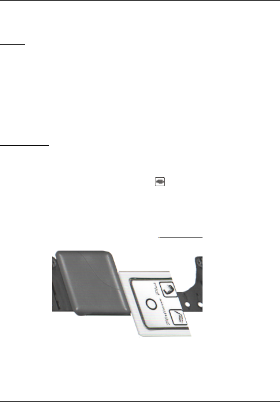
Resetting the PID
The strap sever, PID tamper and case open alarms have the ability to remember if the alarms were ever
activated. This will ensure that should the participant tamper with the PID while away from the area of
confinement the alarm will be reported upon return. These parts of the PID circuitry need to be reset
upon initial installation by using a LOCK. The PID button on the LOCK is used to reset the alarms.
Simply place the LOCK against the reset point (See Figure 2 : Resetting a PID) on the PID and press
the PID button once. The LOCK will emit a special signal (while the red light is on) and reset the
circuitry. See Page 36 for more information regarding Special Function Mode use of a LOCK.
Figure 2 : Resetting a PID