Strix Systems ACCESS-ONE 802.11 a/b/g Wireless Access Point User Manual Manual
Strix Systems, Inc. 802.11 a/b/g Wireless Access Point Manual
Contents
- 1. Access One Quick Start Guide
- 2. AccessOne Network User Guide
- 3. Owners Manual
AccessOne Network User Guide
Access/One™ Network
User Guide

ACCESS/ONE™ NETWORK
User Guide
Part Number: 210-0007-01
Revision A, September 2003
All rights reserved. This document may not be reproduced or disclosed in whole
or in part by any means without the written consent of Strix Systems, Inc.
Strix Systems, Inc.
310 N. Westlake Blvd., Suite 150 • Westlake Village, CA 91362 USA
Tel 805.777.7911 • Fax 805.777.7916
http://www.strixsystems.com
i

FCC Notice
The enclosed wireless network device complies with Part 15 of the FCC Rules. Operation is subject
to the following two conditions:
1. This device may not cause harmful interference.
2. This device must accept any interference received, including interference that may cause
undesired operation.
This wireless network device has been tested and found to comply with the limits for a Class A digital device,
pursuant to Part 15 of the FCC Rules. These limits are designed to provide reasonable protection against
harmful interference in a residential installation. This wireless network device generates, uses, and radiates
radio frequency energy and, if not installed and used in accordance with the instructions, may cause harmful
interference to radio communications. However, there is no guarantee that interference will not occur in a
particular installation. If this wireless network device does cause harmful interference to radio or television
reception, which can be determined by turning the wireless network device off and on, the user is encouraged
to try to correct the interference by one or more of the following measures:
• Reorient or relocate the receiving antenna.
• Increase the separation between the wireless network device and the affected receiver.
• Connect the wireless network device into an outlet on a circuit different from that to which the
receiver is connected.
• Consult the dealer or an experienced radio/TV technician for help.
Industry Canada Notice
This Class A digital apparatus complies with Canadian ICES-003.
Cet appareil numérique de la classe A est conforme à la norme NMB-003 du Canada.
VCCI Notice
This is a Class A wireless network device based on the standard of the Voluntary Control Council for
Interference from Information Technology Equipment (VCCI). If this wireless network device is used near a
radio or television receiver in a domestic environment, it may cause radio interference. Install and use the
wireless network device according to the instruction manual.
European Community (EC) Directives and Conformity
This wireless network device is in conformity with the Essential Requirements of R&TTE Directive
1999/5/EC of the European Union.
Radio Frequency Interference Requirements
This wireless network device is restricted to indoor use due to its operation in the 5.15 to 5.25 GHz
frequency range. FCC regulations require this device to be used indoors to reduce the potential for harmful
interference.
High power radars are allocated as primary users of the 5.25 to 5.35 GHz and 5.65 to 5.85 GHz bands. These
radar transmitters can cause interference with and/or damage to the enclosed device.
RF Exposure Requirements
To ensure compliance with FCC RF exposure requirements, the antenna used for this wireless network
device must be installed to provide a separation distance of a minimum of 20 cm (7.9 inches) or more from
all persons, and must not be co-located or operated in conjunction with any other antenna or radio
transmitter. Installers and end-users must follow these installation instructions.
ii

The Access/One™ Network contains a Lithium battery in the
BME base module which is NOT replaceable by the user
CAUTION:
Discard used batteries according to manufacturer's instructions.
ATTENTION:
Mettre au rebut les batteries usagées conformément aux instructions du
fabricant.
VORSICHT:
Entsorgung gebrauchter Batterian nach Angaben des Herstellers.
Installation Warning
Warning Read the installation instructions before you connect the wireless network device to its
power source.
Warning You must only use the UL Listed power supply supplied with this wireless network device.
Lightning Activity Warning
Warning Do not connect or disconnect cables during periods of lightning activity.
Explosive Device Proximity Warning
Warning Do not operate your wireless network device near unshielded blasting caps or in an
explosive environment.
Important Note:
Intentional or unintentional changes or modifications to this wireless network device are prohibited. Any
such modifications will void the user’s authority to operate the wireless network device, and will void the
manufacturer’s warranty.
MIC Notice:
For additional information, please refer to Strix Systems, Inc., at http://www.strixsystems.com.
iii

Table of Contents
APPENDIX 1: MODULE / DEVICE
MANAGEMENT ................................... 39
INTRODUCTION....................................1
INSTALLATION .....................................2 DEVICE .................................................... 39
CONFIGURE............................................. 40
ASSEMBLY AND SELF IDENTIFICATION ...2 SECURITY ................................................ 43
MANAGER/ONE..........................................2 MONITOR ................................................ 44
HOST NETWORK REQUIREMENTS ...........9
USER SECURITY CONSIDERATIONS .......11 APPENDIX 2: SPECIFICATIONS ..... 46
MANAGEMENT ...................................13 PHYSICAL ATTRIBUTES ......................... 46
EMISSIONS AND SAFETY STANDARDS ... 46
LOAD IMAGE ...........................................16 USER COVERAGE RANGES FOR
BLUETOOTH, 802.11A, 802.11B, &
802.11G.................................................... 47
REBOOT NETWORK ................................17
UPDATE NAMES.......................................17
UPDATE MEMBERSHIP............................18
RENAME NETWORK................................18 APPENDIX 3: CLI COMMANDS....... 48
VIEW ACTION STATUS............................18
NODE STATUS..........................................20
APPENDIX 4: FREQUENTLY ASKED
QUESTIONS.......................................... 54
CONFIGURATION...............................22
NETWORK ELEMENTS............................ 54
SYSTEM CONFIGURATION ......................22 PRODUCT ASSEMBLY AND SETUP.......... 55
STATIC NETWORK SERVERS ..................23 PRODUCT PERFORMANCE...................... 57
WIFI.........................................................24 SYSTEM SOFTWARE AND OPERATION .. 57
ADVANCED WIFI.....................................26 SECURITY ................................................ 59
BLUETOOTH ............................................29 SYSTEM MANAGEMENT ......................... 60
FIRMWARE FTP .......................................30 INSTALLATION CONSIDERATIONS ......... 61
SECURITY .............................................31 APPENDIX 5: SECURITY OVERVIEW
................................................................. 64
WIFI SECURITY.......................................31
NETWORK CONNECT (WIRELESS UPLINK)
SECURITY ................................................33 AUTHENTICATION .................................. 65
ENCRYPTION........................................... 67
WIFI ACL ...............................................34 SOME ATTACK TYPES ............................ 68
BLUETOOTH SECURITY ..........................36 SECURITY DEVICES ................................ 68
IEEE 802.11I........................................... 68
INVENTORY .........................................38 WI-FI AND WPA REQUIREMENTS ......... 69
APPLY CONFIGURATION.................38 GLOSSARY ........................................... 70

USER GUIDE
T
Introdu
his User Guide describes the Strix Access/One Network and its elements. Access/One
Network is a wireless LAN infrastructure that is designed to be simple and secure. This
guide follows the same approach. It is comprised and written as a series of short, simple
and largely independent sections that can be read in any order. This user guide covers
wireless network installation, configuration, security and management. Appendices reference
module management, technical specifications, CLI commands, FAQs and a security overview.
ction
Access/One Network comprises multiple physical network elements – Network Nodes – that
interconnect using either wired 10/100 Ethernet or wireless 802.11 RF links. Every Node in
turn consists of several distinct modules, each serving a different function or enabling a different
device wireless RF technology.
Each Network N ode within the Access/One Network supports any combination of end user
wireless devices that utilize 802.11b, 802.11g, 802.11a or 802.15.1 Bluetooth RF technologies.
Introduction of one of these technologies into the network is a simple matter of adding an
appropriate Wireless Module to each Network Node in the desired coverage area.
Access/One Network requires one Network Server Module to be present for every eight
Network Nodes in the network fabric to handle a variety of internal network protocols and
facilitate distribution of the network control logic.
Each Network Node uses a Base Module that provides power via an external AC adapter and
between 0 and 4 10/100 Ethernet ports for network connectivity. When present, one of the
Ethernet ports provides support for PoE (Power-over-Ethernet).
The Antenna Module rounds out a Network Node and covers all supported RF technologies.
Alternatively Strix’s detachable external antennas, or any appropriate 3rd-party external antennas,
could be used for directionality and/or the increased RF gain required in some situations.
Logically, the network intelligence is fully distributed between its elements. There is no single
point of control and failure. Each network Node is aware of its neighbors and will redirect user
traffic in case of the adjacent Node’s failure or overload.
Access/One Network is managed through a web browser and the Strix Manager/One™
software application. A full network view is presented regardless of the point of browser
attachment. One may configure or monitor the full network, any group of Network Nodes, or a
specific Node down to the individual module level. Telnet is also supported to any module with
use of CLI (Command Line Interface) commands and scripts to manage or monitor it.
A Manager/One plug-in is available for download from the Strix web site. When installed, it is
launched by clicking the Strix icon on the browser’s toolbar. Manager/One will automatically
discover all Strix Access/One Network elements and list them in its window. Double-click on
any listed Network Server and log in – the network is now yours to manage.
1

USER GUIDE
T
Installa
his chapter provides instructions on how to assemble the Nodes and to install and use
Manager/One utility. It also lists the services/servers which Access/One Network
expects to be present in the host wired network infrastructure.
tion
ASSEMBLY AND SELF IDENTIFICATION
Each Network Node arrives in its own well-marked box that contains its disassembled and
individually wrapped constituent modules. The assembly instructions are as simple as ‘snapping’
modules together and plugging the Network Node into a power outlet and, where necessary,
attaching an Ethernet cable. We enclose a four-page Quick Start Guide into every box to walk
you through the process.
If the Strix Architect/One™ application was used to design your network, you should have
received two individualized documents. The first is an inventory list that shows all the Network
Nodes, their names (or numbers), the modules that make up each Node and the modules’ serial
numbers. The second is the coverage area map showing all the purchased Nodes and their
names/numbers. Keep the inventory handy to verify that all Nodes are present and contain the
correct modules, and use the map as a guide to mount/place them in their designated areas.
Assemble the Network Nodes per instructions in the Quick Start Guide, mount or place them
according to the coverage map, and connect all the wires. Your network is assembled and ready.
Please be patient and wait for LEDs on all modules to turn solid green. It will also take several
minutes for the network to go through the self-discovery sequence, assign roles to all the
Wireless Modules, scan the channels for the optimal performance and coverage, and obtain IP
addresses, etc.
Note: You can reset a Network Node to the factory default setting by a) disconnecting the
Ethernet and power cables and b) pressing and holding the reset button (next to the power jack
in the back of the base module) with a paper clip while connecting the power cable again. Hold
the reset button for about 10 seconds – you can release it when the green LEDs on the front of
all modules start flashing fast. Let the Node finish its reset sequence (wait for LEDs to go solid
green); plug back the Ethernet cable if necessary, and reboot the Node by removing and
reinserting the power cord.
MANAGER/ONE
The Manager/One plug-in must be installed on your PC to facilitate discovery and management
of all the Access/One Network elements. When installed, Manager/One lists all the available
Network Servers – points of attachment to Access/One Network for the administrator to
manage it. It also allows the user to page, ping or Telnet into any listed module.
2
USER GUIDE
To install Manager/One, follow these simple steps:
1- Download the Manager/One plug-in file (.zip) from http://www.strixsystems.com
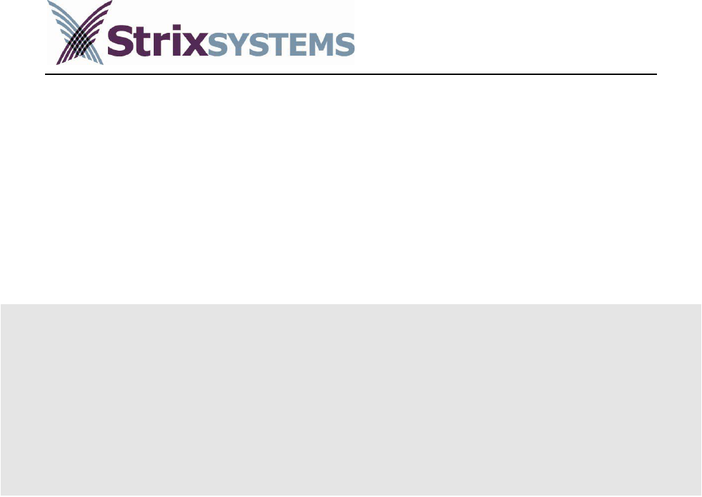
2- Open the zip file and run the setup.exe file. The following window will appear:
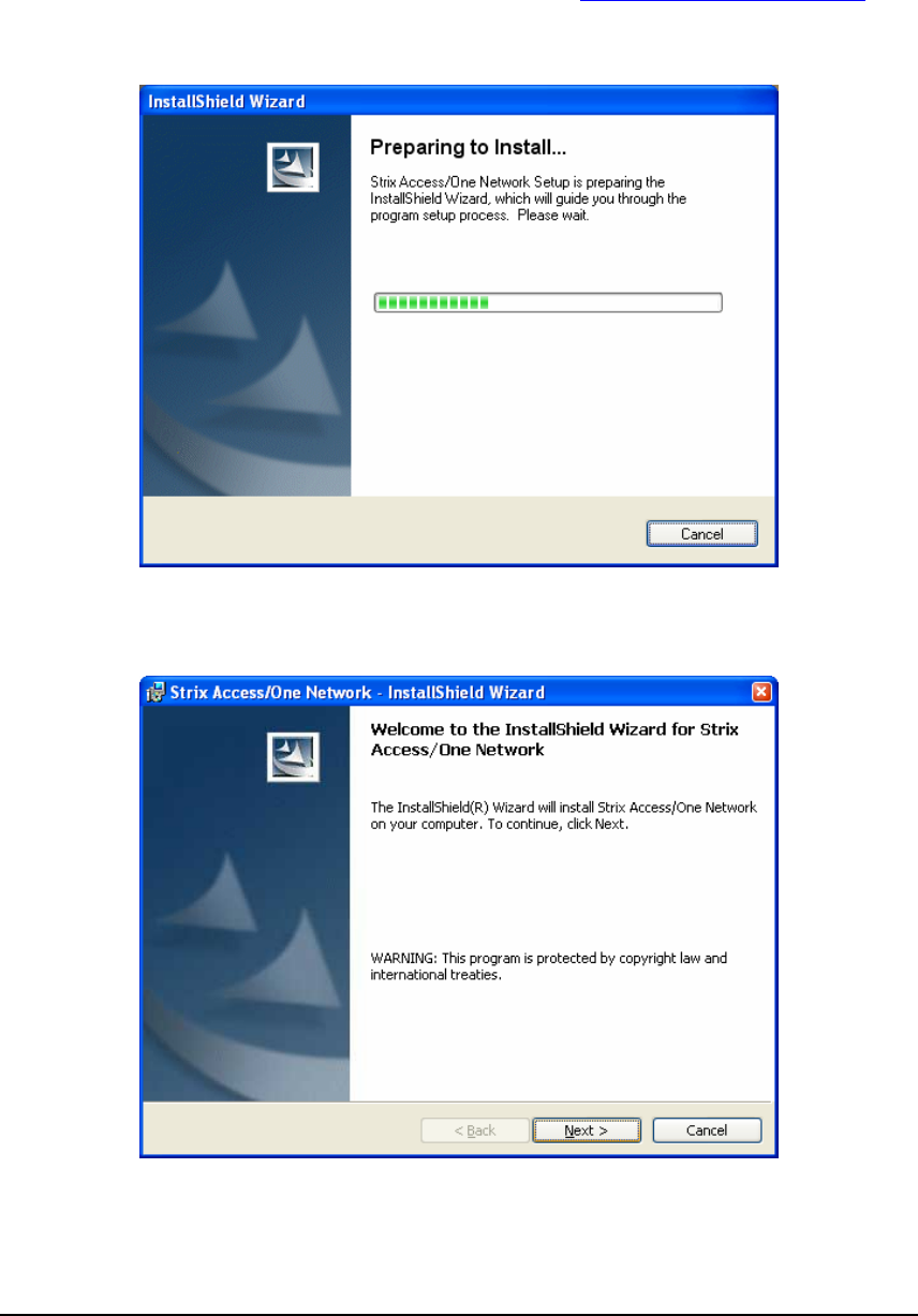
3- After a few seconds the following window will appear. When it does, click on the ‘Next’
button.
3
USER GUIDE
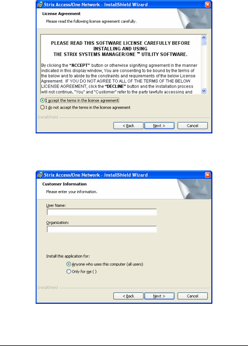
4- When the following window appears, read the Software License, select “I accept the
terms in the license agreement” and click the ‘Next’ button. If you select “I do not
accept the terms in the license agreement” the installation will terminate.
5- When the following window appears, enter your User Name and your Organization,
and select who the application will be installed for (“all users” or “me”). Click the ‘Next’
button when ready.
4
USER GUIDE
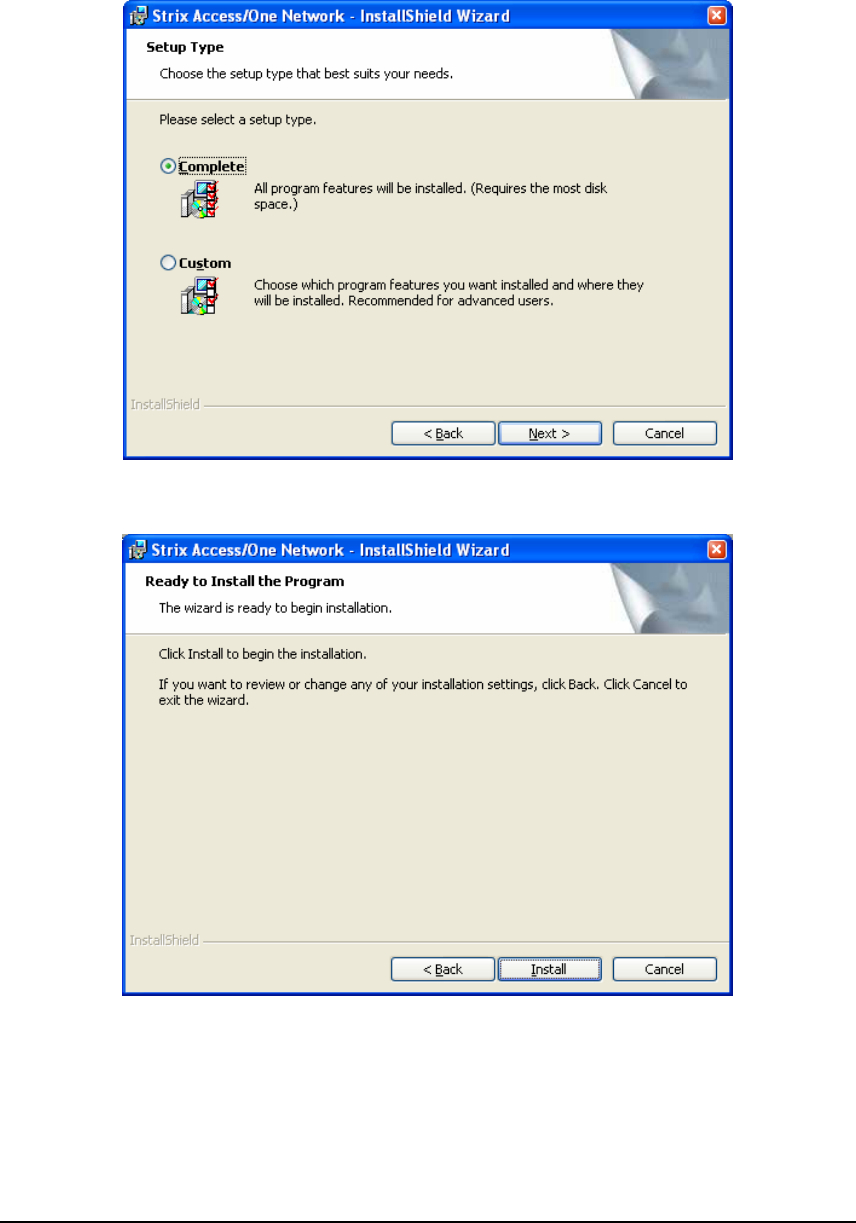
6- When the following window appears, select “Complete” as the setup type and click the
‘Next’ button.
7- When the following window appears, click the ‘Install’ button.
5
USER GUIDE
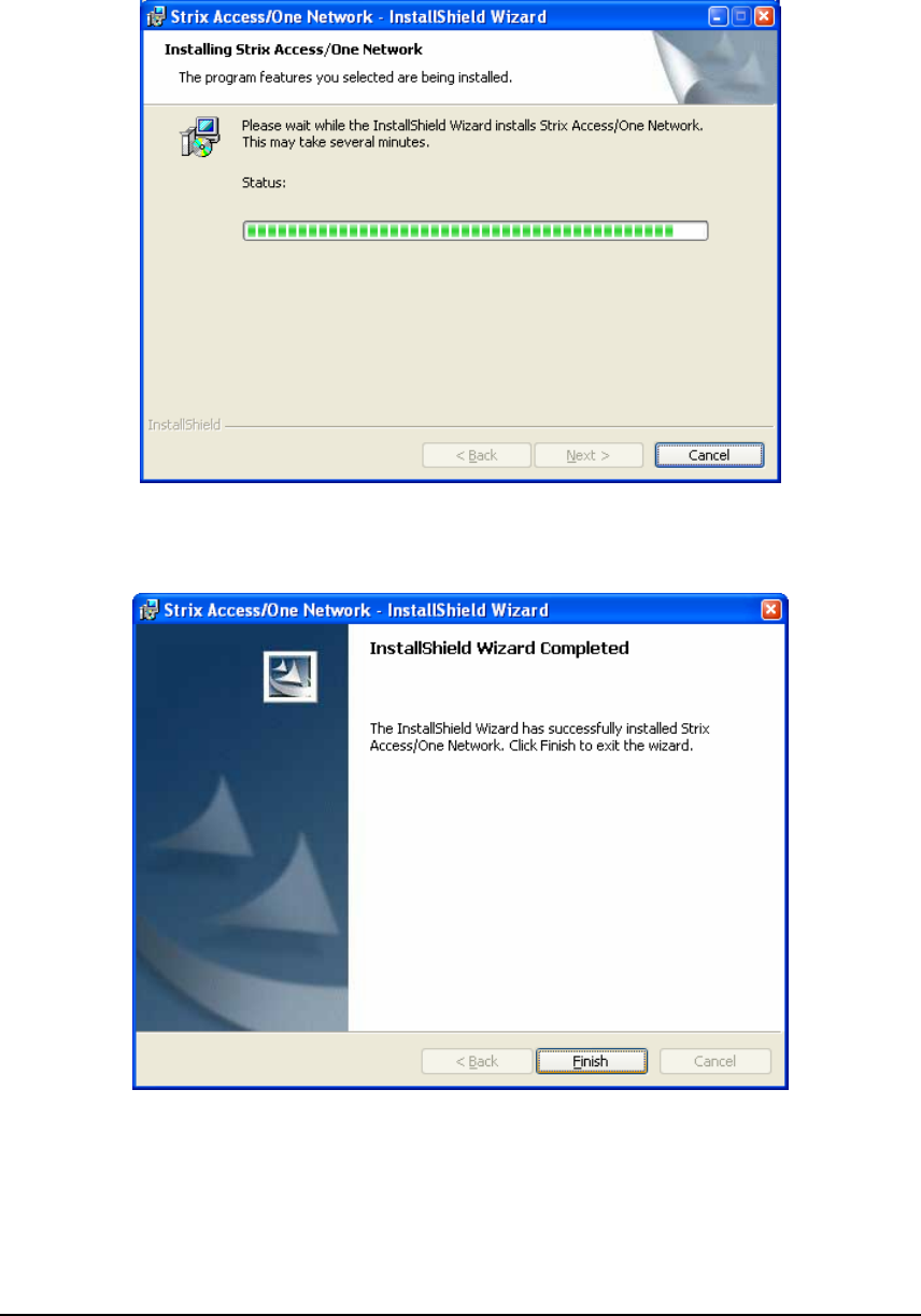
8- The following window will then appear. The installation process can be cancelled at any
moment by clicking the ‘Cancel’ button.
9- When the following window appears, click the ‘Finish’ button to complete the
installation process.
6
USER GUIDE
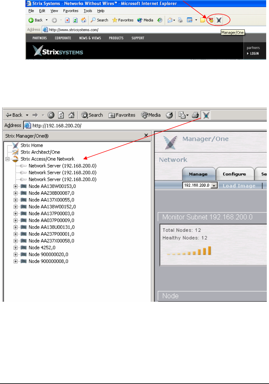
10- The next time you launch your Web browser, a Manager/One icon will be placed in the
top menu, similar to the figure below.
11- The Manager/One installation is now complete!
When you click the Manager/One button (Strix logo) in your browser, you will launch the
Manager/One utility, and the following window panel will appear on the left side of the screen:
The Manager/One utility window contains a link to the Strix Systems Home Page, a link to the
password-protected Strix Architect/One software, and your Strix Access/One Network. A list
of Access/One Network Nodes, listed by label (Base Module serial number by default), will be
displayed below the Access/One Network heading as the Nodes are automatically discovered.
7
USER GUIDE
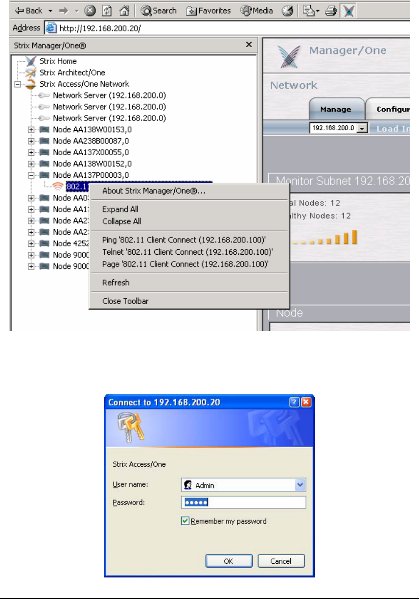
You can now select (double-click) any Node in the list to expand it, and right-click on the
selected module to page, ping, or Telnet into it as shown in the figure below:
To manage Access/One Network click on any listed Network Server, which you will see when
you expand a Node that contains one. A login window (shown below) will appear and the
Manager/One utility window will close.
8

USER GUIDE
Enter the administrator User Name – “Admin” and a Password. The default password is
“Admin” but we strongly recommend that you to change it immediately after logging into the
Manager/One application. Click the ‘OK’ button to login to Manager/One.
An initial network view page will appear. Refer to the Management and Configuration section
for more information about how to use Manager/One to configure and manage your network.
HOST NETWORK REQUIREMENTS
Access/One Network requires the presence of several network servers/services in the host
wired network. These are:
DHCP server
– is necessary to distribute IP addresses and ancillary information to the
Access/One Network. Many routers contain DHCP servers and allow the specification of
DHCP options necessary to provide network information otherwise configured by hand. Strix
recommends each module be given a DHCP reservation allowing it to obtain the same IP
address whenever required. The reservation is based on MAC address and may allow
administrator to specify options unique to a module as well as a network. The Access/One
Network modules require the following option numbers (RFC 2132) to be specified:
Option
Number Title Description
1 Subnet mask Network subnet mask as applied to the given IP address
2 Time Offset Number of hours the DHCP client will add or subtract from SNTP time
3 Default Router Specifies the default gateway for this network segment
6 DNS Server Specifies one or two DNS servers in order of precedence
12 Host Name Specifies the unique system name of the module
15 Domain Name
Specifies the domain name for this network. This is used to fully qualify any
hostname operations the module may generate (i.e. ping node1 = ping
node1.strixsystems.com). Applies to module operations only, doesn’t affect users.
42 NTP server Specifies the NTP server IP address (local or internet)
The DHCP lease time should be infinite whenever possible to prevent interruption in service,
although Strix recommends configuring a reservation for each Access/One Network module to
prevent issues regardless of the lease time and in order to maintain management consistency.
DHCP server examples are: Windows 200X Server, Cisco IOS, Linux, Sun OS, etc.
9

USER GUIDE
FTP server
– is required to transfer firmware and configuration from distribution media to
Access/One Network modules. Software distribution via an FTP server relies on user accounts
to maintain security. Access/One Network modules are capable of specifying a user name and
password (including anonymous) to log into an FTP server. Directory access may be
configurable based on the FTP server software, so Access/One Network related files may be
available only to Access/One Network modules. TFTP is not currently supported.
Examples of FTP servers are: Windows 200X Server, Linux, Sun OS, and many shareware /
freeware implementations.
Internet browser
– Access/One Network and Manager/One are supported in Windows
Internet Explorer v6.0 and above.
Single/Multiple Subnet
– Access/One Network uses broadcast and multicast packets to
maintain management connectivity. If subnet space is an issue, using NAT (Network Address
Translation) at the Access/One Network boundary and specifying a class B subnet should be
sufficient. A global network may present an unavoidable multi-network configuration which
may be managed by specifying an IP address of an Access/One Network Server in each subnet
as described later in this guide.
Power-over-Ethernet (PoE)
– may be used to provide primary or backup power to the
Access/One Network Nodes. If you want to use the PoE feature, PoE injectors or PoE
enabled switches must be present on the host network. One caveat is that the PoE must come
straight from the supplying device; it won’t pass through intermediate switches. Currently,
Access/One Network supports the following versions of PoE: 802.3af and Cisco proprietary.
10

USER GUIDE
USER SECURITY CONSIDERATIONS
The topic of security may be split into two categories: network-level security (inter-Network
Node) and user security (station/user device to Network Node). Network-level security is an
integral part of the Access/One Network and requires no external resources. User security may
require an external resource (such as a RADIUS server), specific hardware (an AES capable
NIC), or even a redundant security system (like a VPN client/server) depending on the level of
user security desired. Adherence to newer security standards (WiFi WPA and IEEE 802.11i) will
require a RADIUS server supporting EAP at a minimum. The following table summarizes the
levels of wireless security typically available in an 802.11 network:
Minimum Better (WPA) Best (Strix)
Authentication
Local
MAC address
control list
Remote
802.1x EAP
Remote
802.1x EAP
(TLS or TTLS)
Encryption Static WEP 128-bit WEP with TKIP
(or Dynamic WEP) Dynamic AES
Supplemental
Requirements None RADIUS server
RADIUS server
AES NICs
Achieving a secure network requires that the user authenticate to the Network Node to validate
that the user is allowed access to the network and the data must then be encrypted to prevent
other users from eavesdropping. Some definitions may help to clarify your security choices:
Cipher Types
– The Access/One Network supports both the WEP and AES cipher suites. A
more detailed discussion regarding these can be found later in this user guide. In summary, the
older WEP cipher has been shown to have significant weaknesses. Since WEP is widely
deployed, the WiFi WPA specification is designed to address these weaknesses and should only
require a driver update to realize these benefits. The 802.11i specification (a superset of WPA)
also requires a newer cipher, AES, which has additional benefits but also an additional cost
(AES typically requires hardware acceleration which only newer NICs support).
Key Types
– The previous table indicates that there are both static and dynamic cipher keys.
The distinction is how individualized the key is per user device/station. A static default key is
configured within the Access/One Network Node and the same key is used for each station
(unicast and multicast traffic). A unique static key provides additional protection by assigning a
specific, unique key to each station for unicast traffic based on MAC address. This is more
secure but not very scalable. A dynamic key is generated for each user by the network-based
RADIUS server when the user remotely authenticates. The key is dynamic because it is created
when the user authenticates and will change every time the session begins. This is more secure
because the key isn’t manually administered and changes frequently.
11

USER GUIDE
Local Authentication
– The Access/One Network is responsible for determining whether the
user device/station has network privileges. Since most access points don’t have a user database,
there is typically very little information for a system like Access/One Network. One mechanism
to determine user privileges is an Access Control List, which disallows (or allows) any user based
on their MAC address. However, MAC addresses can be spoofed so this method is not secure.
Remote Authentication
– Access/One Network becomes a gatekeeper and requires the use of
an external RADIUS server on the LAN to determine which users/stations are granted access.
The RADIUS server has a list of users and passwords to validate the user or device (one is more
secure than the other) and dynamically generate a key to Access/One Network for this user or
device. The RADIUS server must support EAP encapsulated RADIUS exchanges, as
Access/One Network only supports this format. When remote authentication is enabled, only
EAP traffic is bridged to the LAN until the RADIUS server authorizes Access/One Network
to allow the user or device access to the network.
Some examples of devices that support RADIUS with EAP are:
Windows 2000 IAS/Active Directory/Certificate Server (MD5/TLS)
Windows 2003 IAS/Active Directory/Certificate Server (MD5/TLS/PEAP )
Funk Odyssey with Active Directory interface or its own user list
(MD5/LEAP/TLS/TTLS/PEAP) – Note: Microsoft and Funk are the two servers
used for WiFi WPA testing.
Cisco ACS with Active Directory interface or its own user list
(MD5/LEAP/TLS/PEAP)
Linux Cistron Radius server (MD5/TLS)
Meetinghouse AEGIS server (MD5/LEAP/TLS/TTLS/PEAP)
Interlink Secure.XS server (MD5/LEAP/TLS/TTLS/PEAP/SPEKE)
Good security may be achieved by using Windows 200X IAS/Active Directory or Linux
RADIUS with TLS certificates. The best security will be provided by using Windows 2003
IAS/Active Directory, Funk Odyssey or Cisco ACS etc. running TTLS or PEAP.
Access/One Network provides encrypted protection from the user device/station to the host
LAN. If security on the LAN is also an issue, a Virtual Private Network (VPN) may be used to
doubly secure the wireless traffic while providing protection on the LAN. Due to the significant
overhead associated with this method, additional performance penalties will occur.
12
USER GUIDE
M
Manage
Anagement of the Access/One Network has been designed to be as simple as
possible. This chapter describes the network views, naming conventions and rules to
include and associate a newly installed Network Node as part of your Access/One
Network. Visual cues are provided that indicate network ‘health’, along with the
presence of unattached or rogue Node/devices. Explanations of other management windows
are also provided, such as the Node detail and status windows.
ment
Manager/One resides on all Access/One Network modules, but is centrally managed from each
of the Network Server Modules. In addition to using the Manager/One utility, using the IP
address of any Network Server as a URL within Internet Explorer will automatically display the
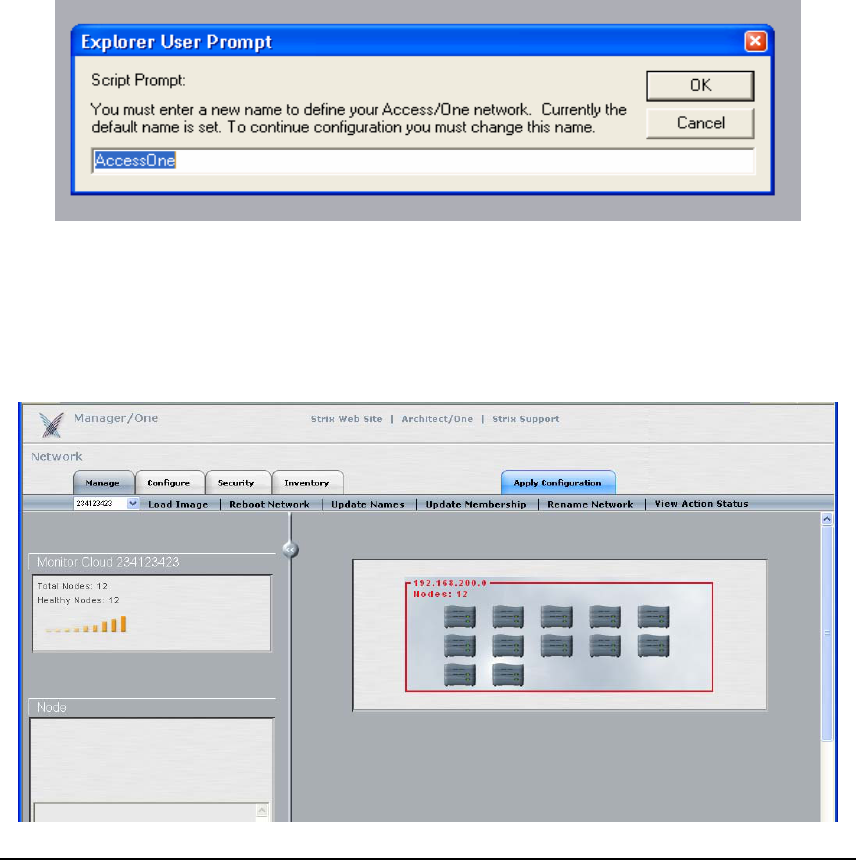
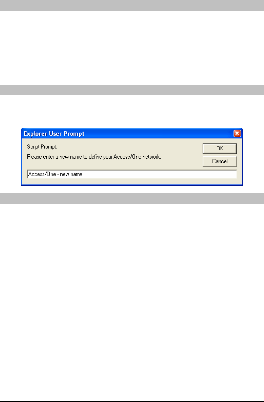
Manager/One screen. The first time Manager/One is accessed on the Access/One Network it
will prompt for a network name change (from “AccessOne”), which is a security feature that
ensures that the default network name is maintained.
After a new network name is created, Manager/One will display a network view with all
discovered Access/One Network subnets and the number of Nodes in each. In the example
below, there is just one IP subnet (cloud). Notice the red color of the frame., which means that
either one or more Nodes within the cloud have not yet been included or configured in the
network, or that there is a fault condition with one or more of the Nodes in the network.
13
USER GUIDE
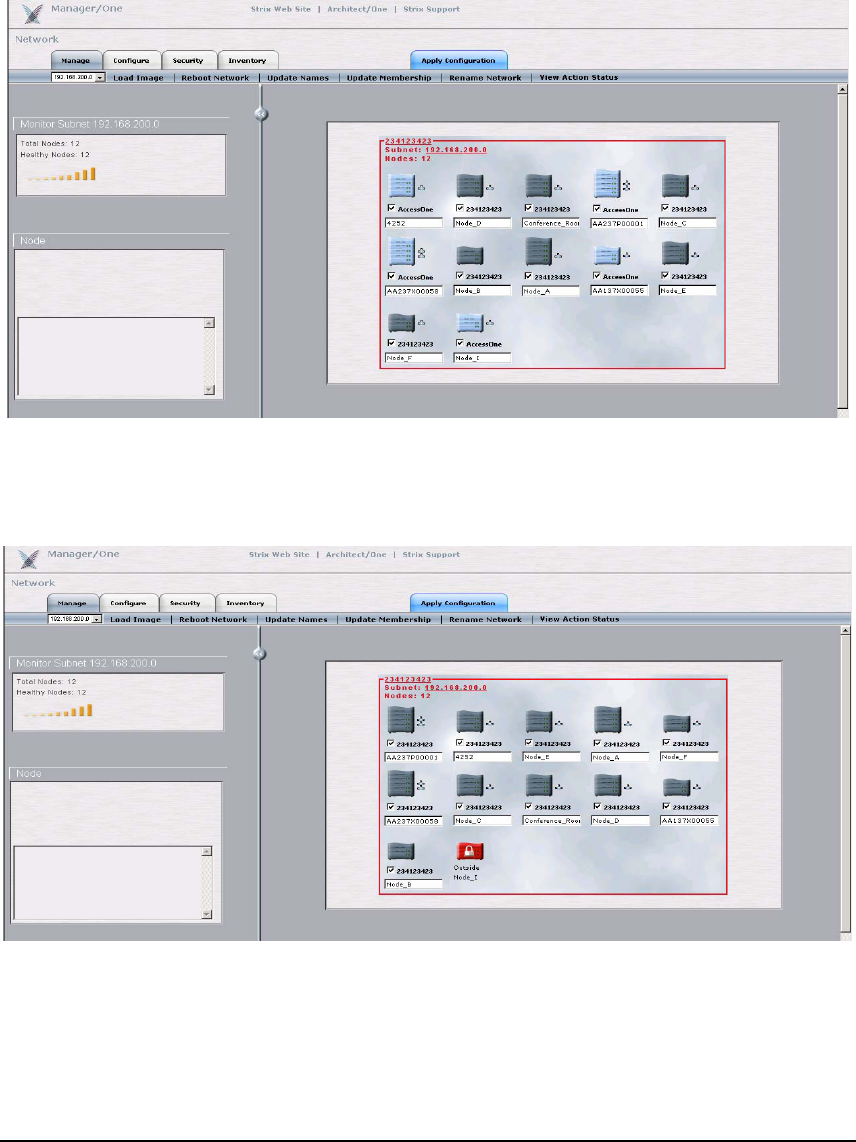
Click anywhere within the frame in order to enter the cloud (IP subnet) and view the details. In
the below example, notice that some of the Network Nodes are sky blue in color and some are
dark grey in color. The Nodes that are sky blue have yet to be included as part of the new
Access/One Network that was named in the previous step and are still associated to the default
network name (AccessOne), as listed below each Node.
To assign any of the sky blue colored Network Nodes to the newly created network, click the
checkbox below each Node to select it and then click the ‘Update Membership’ command in
the toolbar to include the Node into your network.
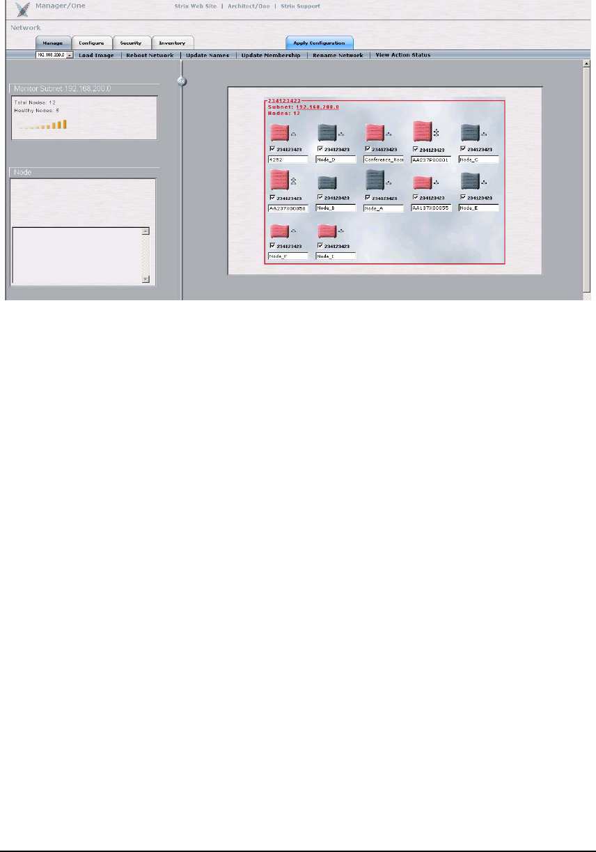
If the ‘Update Membership’ operation was successful the network name below each of the
selected Nodes will have updated to the newly created name, and the Nodes will have changed
from sky blue to dark grey in color, as shown above. The ‘Update Membership’ process can take
up to 30 seconds to take effect. Notice that in this instance one of the Nodes is red with a lock
symbol – Nodes of this type belong to different clouds and cannot be accessed from this screen.
14
USER GUIDE
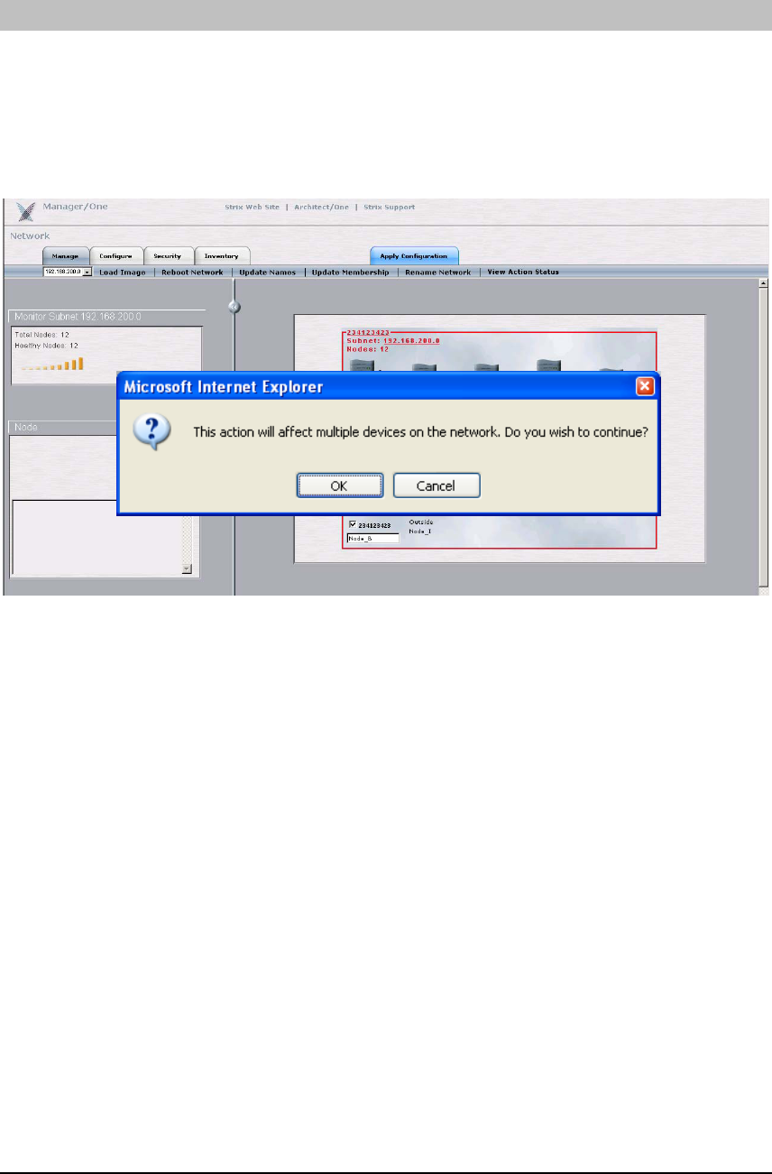
As shown below, if the screen displays Nodes that are red in color but that do not have a lock
symbol on them, these are nodes that are in alert status which should be investigated further.
The white box below each Node is a label provided for Node identification purposes, and is set
as the Base Module’s serial number in the default configuration. This label can be changed to be
more meaningful, e.g. Room123. Modify the label field and click the ‘Update Names’ command
for the Node name changes to take effect. Note: this label name is stored in the Node’s Base
Module, so if the module configuration of the Node is changed the label will remain intact.
The next few paragraphs describe the ‘Manage’ tab in great detail. The actions within this tab
enable the Access/One Network administrator to view & manage the network in its entirety or
to drill down to the subnet, Node, or even device level. To reduce the number of network
resets, it is recommended that the initial cloud configuration be created on the Network Server
before admitting any other Network Nodes to the cloud. When any other Node is admitted, it
will automatically retrieve the cloud configuration and reboot.
Creating a configuration using the ‘Configure’ or ‘Security’ tabs and clicking on the ‘Update’
button will create a local configuration on the Network Server, and when the ‘Apply
Configuration’ tab is selected, that information is pushed to every Node in the network. Once
the configuration has been pushed successfully to the other Nodes (monitor by pressing ‘View
Active Status’), use the ‘Reboot Network’ command to make the changes effective. Note: the
Network Server will not allow additional management changes (the various tabs will be shaded)
until the previous command has completed.
15
USER GUIDE
LOAD IMAGE
Click on the ‘Load Image’ command in the ‘Manage’ sub menu to send the command to load a
new image to each of the modules in all of the Nodes within the network. The parameters of
the FTP location where the new software image resides should be set via the ‘Configure’ tab
(use the ‘Firmware FTP’ command in the submenu) before attempting to load a new image to
the network. Loading a new image will require all Nodes within the network to reboot by using
the ‘Reboot Network’ command.
16
USER GUIDE
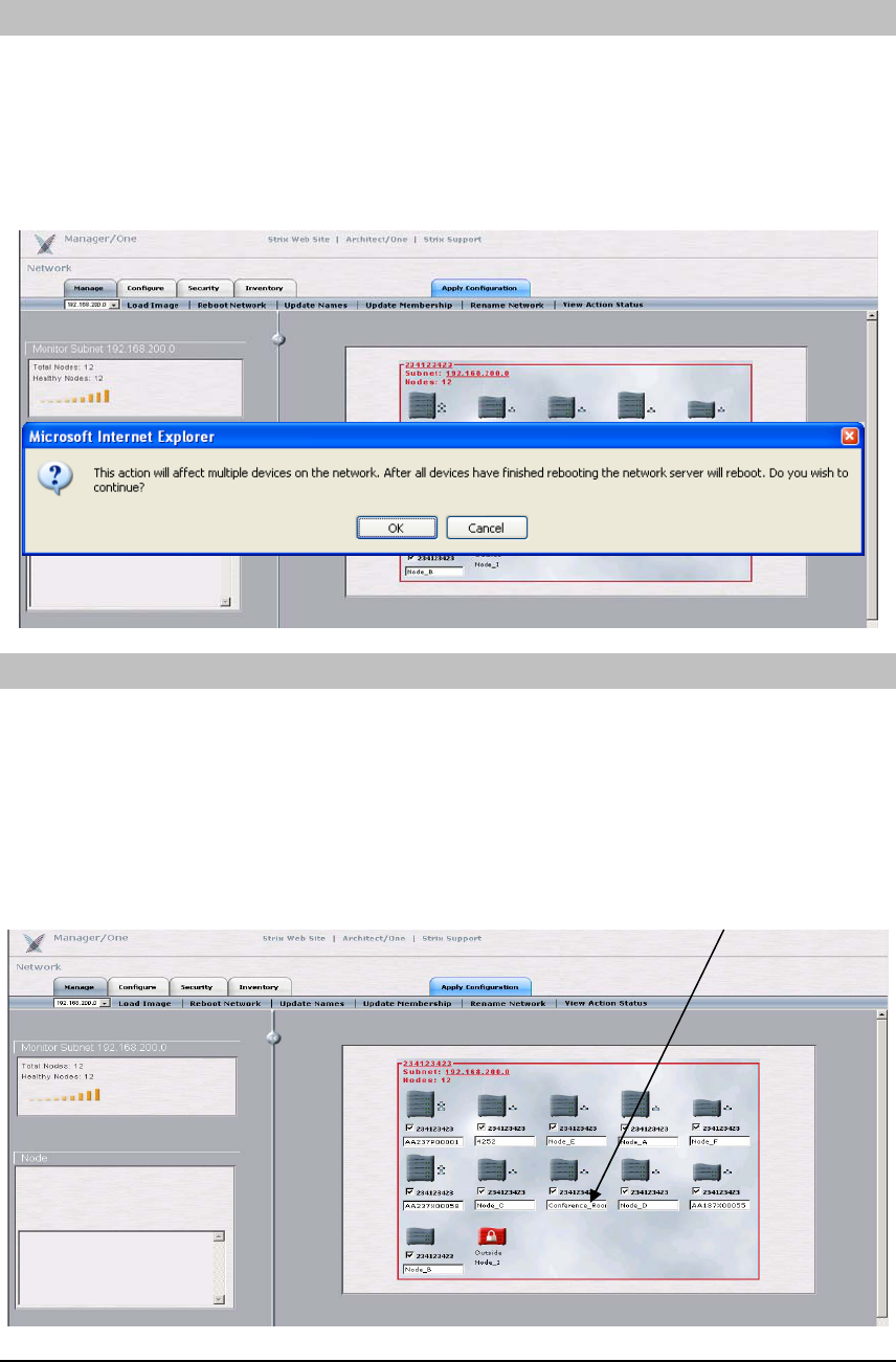
REBOOT NETWORK
The ‘Reboot Network’ command will reboot each of the modules in all of the Nodes within the
Access/One Network. This is required when network-level configuration changes are made or a
new image is loaded. The Network Server will generate the request in stages in order to monitor
the progress of the network reboot. Once each module reports receiving the reboot command
and successfully reboots (monitor by pressing ‘View Active Status’), the Network Server will
perform a final self-reboot.
UPDATE NAMES
Each Network Node has an editable text field beneath the Node image showing the Node’s
current name (default is the Base Module serial number). A Node name can be up to 15
characters in length & any alphanumeric character may be used. The Node name must be
unique within the wireless network. A duplicate name will cause Manager/One to prompt for a
new name. Changes to Node names are applied using the ‘Update Names’ command. A name
update does not require a reboot, but may take 10-15 seconds before the change is reported.
Refresh the browser window frequently to display the latest network information.
Node Name
17
USER GUIDE
UPDATE MEMBERSHIP
The cloud display indicates all of the Network Nodes in the network (including rogue Strix
Nodes). Nodes which belong to the Network Server cloud name are dark grey in color and have
a checkbox that is checked. Nodes which are sky blue in color and have an unchecked checkbox
are not part of the cloud but may be admitted. Nodes which have no checkbox or are red with a
lock symbol may not be admitted to the cloud. Adding or removing Nodes from the cloud is
accomplished by checking or unchecking the checkbox and selecting the ‘Update Membership’
command. This will result in a reboot of Nodes which have changed status. Access/One
Network Nodes not admitted to a cloud name other than default will not bridge user traffic.
RENAME NETWORK
The administrator can use this command to rename the Access/One Network. Any device that
belongs to this network will then be admitted to the new network name without requiring a
network reboot.
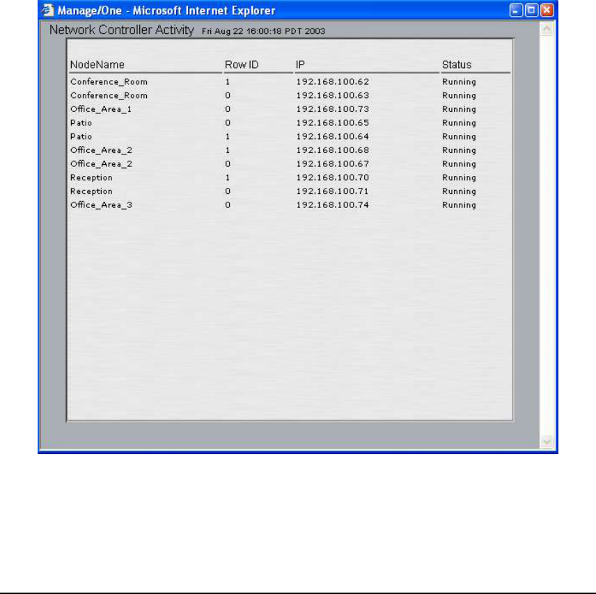
VIEW ACTION STATUS
This command launches a separate window displaying a list of all the modules within the
wireless network. This list consists of a Network Node name, the device stack order (Row ID),
the IP address of the module and its current status. This window gives the most current status
because the information is refreshed every 5 seconds. The list below provides details on what
type of information the action status window provides. Note that some status values can occur
too quickly for observation. The display shows the last command sent to the module and the
pending status of that command.
Commands issued to an Access/One Network module:
Page: Toggle paging on or off
Apply Configuration: apply the configuration in the Network Server to the entire network
Image Load: download the software image as specified in the Firmware FTP settings
Prepare to Reboot: The module has received a command to anticipate a reboot
Stop Reboot: Halt the current reboot process, may be issued following the Prepare to
reboot command
Reboot: Execute the reboot
Include: Add this Node to the cloud
Exclude: Remove this Node from the cloud
Change Stack Name: change the Node name
18
USER GUIDE
Status results of commands issued to an Access/One Network module:
Running: there are no pending commands against this module and it is communicating
with the Network Server
Link Lost: Manager/One has lost contact with this module for more than a minute
Command Started: Manager/One is attempting the command
Command Sent Successfully: the command was received by the module
Command Sent: the module replied that it was received
Command Executed Successfully: the command was executed on the module
Command Not Sent: Manager/One failed to send the command to the module
Command Sent. No response from device: Manager/One sent the command but the
module didn’t reply
Command Failed: The module received the command but failed to execute the
command
19
USER GUIDE
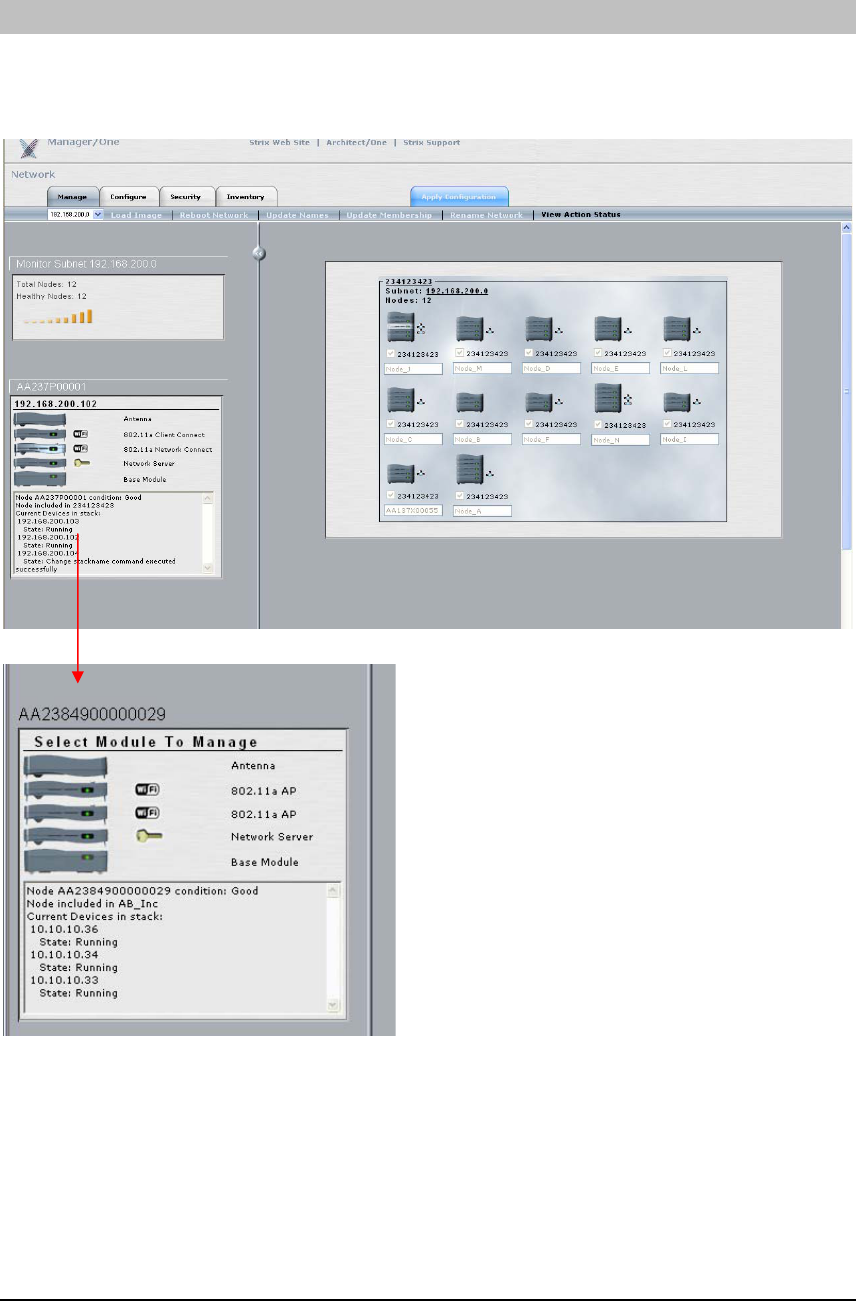
NODE STATUS
Selecting any Node listed on the network view will update a frame on the left side of the
window showing the Node’s status and its components. You may close this frame at any time
by selecting the “<<” button on the line separating the frames.
This frame shows all the Node components, their
roles, IP addresses and status. Double-clicking on
one of the modules takes you directly to the
management screen for that module and opens a
new Manager/One window with module-level
commands and screens similar to the ones
available for the network configuration. Use this
utility to monitor and manage the module itself,
and to perform module-specific configurations
such as setting a unique SSID, etc.
Note: For module-specific Manager/One capabilities please refer to Appendix 1. It is generally
sufficient to configure the network as a whole without configuring specific modules or Nodes.
When a specific device is configured (as outlined in Appendix 1), the manually configured
parameters override the global network parameters configured or defaulted at the network
(cloud) level. It is presumed that if a module is manually configured, the configured parameter
values take precedence over global values.
20
USER GUIDE
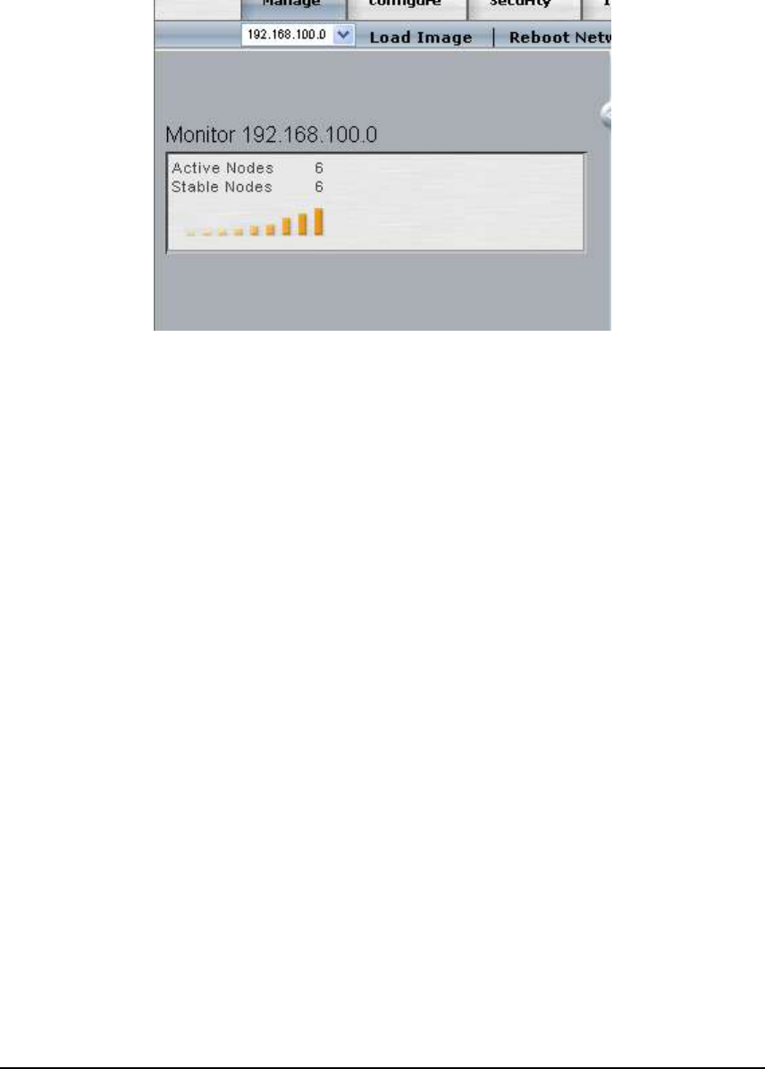
The Monitor frame in the main network window presents a summary of the network health.
Nodes under heavy load or losing management connectivity are considered less stable and will
not be counted as a stable Node in the Access/One Network.
21
USER GUIDE
U
Configu
se information in this chapter to configure all or any subset of Access/One Network
Nodes simultaneously. Individual modules within the Nodes will present similar
configuration screens if and when you drill down to the module-level configuration
screens. Module-level configuration is described in Appendix 1.
ration
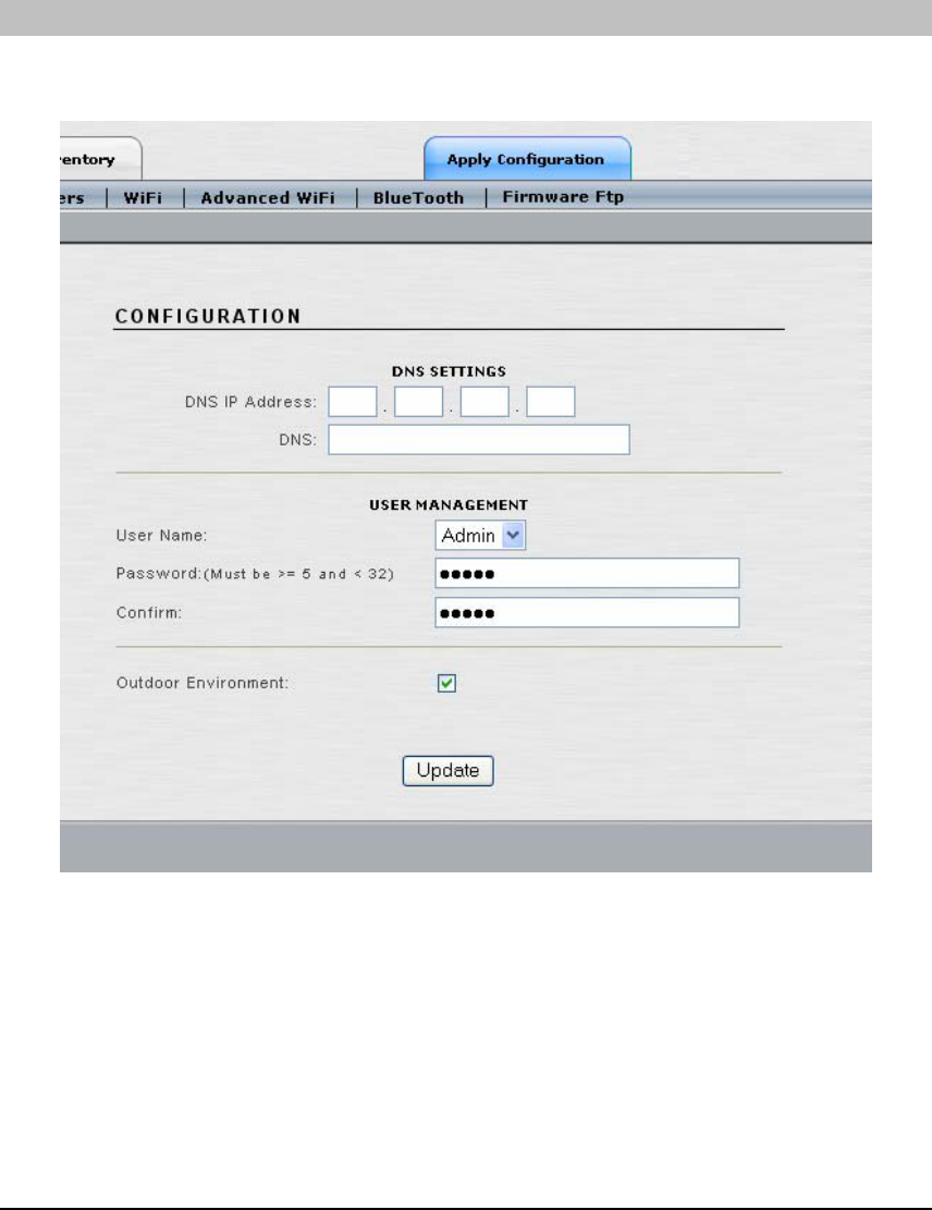
SYSTEM CONFIGURATION
The system configuration allows the following changes to be made: DNS settings, administrator
password, or outdoor environment selection.
• Domain Name Server (DNS) IP Address: Enter the DNS IP address of the primary
and secondary DNS. The DNS is used by the Access/One modules to lookup the
names of various servers (e.g., RADIUS server, FTP server, etc.). The Domain Name
may be specified when static IP addresses are used. This will have the effect of
appending the domain name to non-fully qualified address requests (e.g. FTP server
host name configured as FTP123 will become FTP123.strixsystems.com.)
22
USER GUIDE
Note: When using wireless uplinks between Network Nodes, the Access/One Network
self tuning process requires that a default gateway and/or DNS be specified to determine
delays to the host Ethernet. If DHCP is used throughout the network (default setting),
specifying both of these as part of the options will satisfy this requirement. Otherwise, if
static IP addresses are configured, the default gateway must also be configured to allow
correct operation of the self tuning feature.
• User Name: Enter the user name that is required to access the web server interface
within the Network Server Module. The default value for the User Name is ‘Admin’.
The user name is case sensitive.
• Password: Enter the password that is required to access the web server interface within
the Network Server Module. The default value for the Password is ‘Admin’. The
password is case sensitive. Note: We strongly recommend changing the Admin
password immediately after the initial login to the Access/One Network.
• Confirm: If you typed a new password in the ‘Password’ field, retype the same
password in this field in order to confirm the password change. Note: Performing this
action will permanently change the login password.
• Outdoor Environment: Check this item if the Access/One Network Node is going to
be installed in an environment with uncontrolled temperature. The affected Nodes will
set the appropriate temperature regime and corresponding fan speed to better survive in
these types of environments.
Click the ‘Update’ button at the bottom of the page to save any changes made to the settings in
this page. Click the ‘Apply Configuration’ tab to make the configuration information active in
the Access/One Network cloud.
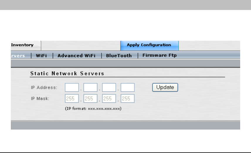
STATIC NETWORK SERVERS
When your Access/One Network spans multiple IP subnets, it is necessary to enter an IP
address of at least one Network Server Module that resides on each of the other subnets so that
all of the subnets can be managed from within a single Manager/One browser window.
23
USER GUIDE
• IP Address: Enter the IP address of a Network Server Module on another subnet.
• Subnet Mask: Enter the subnet mask of the Network Server Module on another
subnet.
Click the ‘Update’ button to save any changes made to the settings in this page. The listed
Network Server will be added to the internal list as a Network Server that is available on another
subnet, and the IP Address field will clear. Multiple Network Server IP addresses can be added.
When you have finished adding Network Servers click the ‘Apply Configuration’ tab to make
the configuration information active in the Access/One Network cloud.
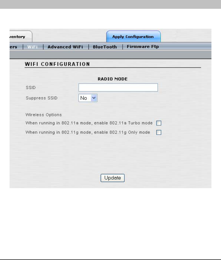
WIFI
The Wi-Fi network settings can be configured from this window, including SSID, SSID
parameters, and 802.11a and 802.11g Wireless options.
• SSID: This field defines the identifier of the Service Set to which all the Access/One
Network Wireless Modules belong. User devices must provide this SSID to connect to
Access/One Network. You may enter an alphanumeric string that is between 1 and 32
characters in length that user devices will associate with in Infrastructure mode. If you
want to assign a unique SSID to a specific Wireless Module, drill down to the module
itself and update the System Name field to set a unique SSID for the device.
24

USER GUIDE
• Suppress SSID: Select ‘Yes’ if you want to prevent the broadcast of the SSID in
beacons from all Wireless Modules in the Access/One Network (recommended).
• Enabling 802.11a Turbo Mode: Clicking on the ‘enable 802.11a Turbo mode’
checkbox will configure all 802.11a Wireless Modules in the Access/One Network to
operate in Turbo Mode. In this mode the 802.11a Wireless Modules will operate with
data rates at speeds up to 108 Mbps. This translates to nearly double the throughput,
but there are some limitations. These limitations are as follows:
o Only three operating channels are supported, as opposed to eight channels in
non-turbo mode.
o All user devices must also be capable of and configured for 802.11a Turbo
Mode. Note: Turbo Mode is not an industry standard and so not all 802.11a
user devices support this feature.
• Enabling 802.11g Only Mode: Clicking on the ‘enable 802.11g Only mode’ checkbox
will configure all 802.11g Wireless Modules in the Access/One Network to support
802.11g only. In this mode each 802.11g Wireless Module will only support 802.11g
user devices, which will improve the performance of the 802.11g network. If this mode
is not enabled (default configuration) the 802.11g Wireless Modules will support both
802.11b and 802.11g user devices simultaneously. Note: When this mode is enabled, all
802.11b user devices will loose connectivity to the 802.11g Wireless Module.
Click the ‘Update’ button at the bottom of the page to save any changes made to the settings in
this page. Click the ‘Apply Configuration’ tab to make the configuration information active in
the Access/One Network cloud.
25
USER GUIDE
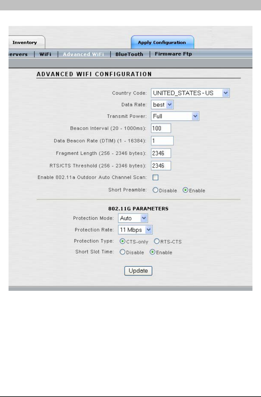
ADVANCED WIFI
Advanced Wi-Fi network settings are configurable from this window.
• Country Code: The Regulatory Domain for all Access/One Network Node is pre-
configured in manufacturing and can not be changed by the user. The Node will ship
with a default country setting, which may not be the country in which you reside. It is
important that you set the Country Code in order to abide by the wireless laws within
your country. Click on the drop-down list and select the appropriate country within the
regulatory domain in which the Access/One Network will operate.
26

USER GUIDE
• Data Rate: Select a data transmission rate from the drop-down menu. The ‘best’
selection will adapt the rate to the best available. Alternately, the user has the option of
selecting a fixed data rate, but if that data rate is unachievable no connection will be
made. The default value is ‘best’. The Wireless Modules will adjust the data rate
automatically based on the noise conditions, distance to the connected user device, etc.
so Strix does not recommend changing this parameter.
• Transmit Power: Select the Wireless Modules’ level of transmit power from the drop-
down list box. The choices are Full, Half (-3dB), Quarter (-6dB), Eighth (-9dB) and
Minimum. Decrease the transmit power if you wish to decrease the range of the
Wireless Modules in the Access/One Network. The default value is ‘Full’. Note: the
Wireless Modules themselves will adapt to the conditions in the RF ‘neighborhood’
automatically, so Strix does not recommend changing this parameter.
• Beacon Interval (20 - 1000ms): Enter a value between 20 and 1000 in milliseconds
that specifies the Beacon Interval. The default value is 100.
• Data Beacon Rate (1 - 16384): Specifies the Data Beacon Rate. Enter a value between
1 and 16384 that specifies the Delivery Traffic Indication Message (DTIM). Increasing
this interval allows the station to sleep for longer periods of time resulting in power
savings in exchange for some degradation in performance. The default value is 1.
• Fragment Length (256 - 2346 bytes): Enter a value between 256 and 2346. This
fragment length setting will determine the frame size of the wireless frame. Wireless
frames will be reassembled by the Access/One Network Wireless Modules before being
forwarded to the Ethernet port, provided the frame is smaller than the Ethernet MTU
(1536 bytes). The default value is 2346.
• RTS/CTS Threshold (256 - 2346 bytes): Enter a value between 256 and 2346 that
specifies the RTS/CTS threshold. The default value is 2346.
• Enable 802.11a Outdoor Auto Channel Scan: Certain countries provide for different
indoor and outdoor frequencies/channels. Depending on the Country Code selected in
the Country Code field, use this checkbox to enable/disable the use of outdoor channel
frequencies. Selecting this checkbox will enable the Auto Channel Scan to search
through the outdoor frequency list. The default value is deselected/disabled.
• Short Preamble: The short preamble improves network efficiency by reducing the
preamble from 128 bits to 56 bits. This is an optional feature within the 802.11b standard
and most 802.11b NICs support short preambles. 802.11g is required to support both
short and long preambles. This does not apply to 802.11a.
27

USER GUIDE
• Protection Mode: 802.11b and 802.11g networks may occupy the same frequency
range, but they don’t speak the same language (802.11b uses CCK while 802.11g uses
OFDM). To co-exist within the same space, 802.11g must make allowances for 802.11b
by using CCK for a short period of time (RTS or Request To Send). Selecting ‘Auto’
detects the presence of 802.11b and automatically begins protection. Selecting ‘None’
will not provide protection under any circumstances. Selecting Always will always
provide protection even if 802.11b is not present.
o Enabling this feature will reduce 802.11g performance. However, if protection
is disabled and 802.11b clients are present on the same channel, 802.11g
performance will be affected because there will be collisions.
• Protection Rate: Determines the rate to generate the RTS/CTS frames when
protection mode is enabled.
• Protection Type: The protection will apply to CTS (Clear To Send) or both RTS and
CTS. The RTS-CTS setting provides more robust protection but performance will be
reduced for 802.11g.
• Short Slot Time: If the network contains a combination of 802.11b and 802.11g user
devices, enabling this will give precedence to 802.11g traffic.
Click the ‘Update’ button at the bottom of the page to save any changes made to the settings in
this page. Click the ‘Apply Configuration’ tab to make the configuration information active in
the Access/One Network cloud.
28
USER GUIDE
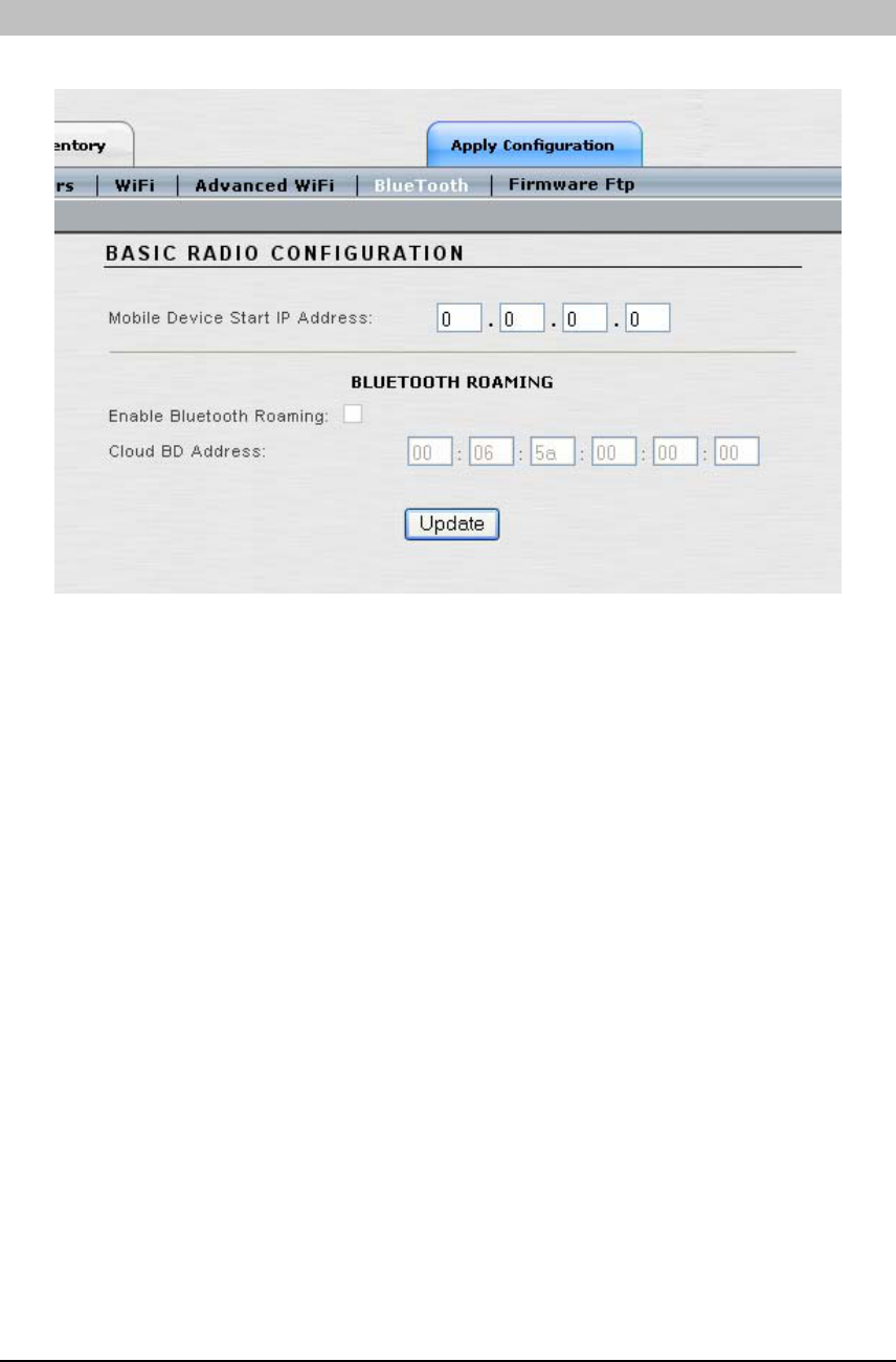
BLUETOOTH
This window defines the network settings for Bluetooth.
• Mobile Device Start IP Address: Enter the starting IP address for mobile Bluetooth
devices. This is the beginning address of the address pool from which all user device IP
addresses will be assigned. The mobile device IP address pool consists of the next
twenty (20) IP addresses starting from the Start IP address. Other Bluetooth devices
should not use this pool of 20 IP addresses.
• Enable Bluetooth Roaming: When enabled, Bluetooth user devices can freely move
throughout the Access/One Network coverage area, between Network Nodes, without
loosing connection to the network. The connection/association is seamlessly handed
over from one Network Node to another without affecting user experience.
• Cloud BD Address: This is an address to be used by all Bluetooth users to connect to
Access/One Network. This single address represents all Bluetooth Wireless Modules in
the Access/One Network, so that user devices do not have to be reconfigured while
roaming throughout the Access/One Network coverage area.
Note: The last two features require the Bluetooth Mobility Software option to be loaded,
which must be purchased separately.
Click the ‘Update’ button at the bottom of the page to save any changes made to the settings in
this page. Click the ‘Apply Configuration’ tab to make the configuration information active in
the Access/One Network cloud.
29
USER GUIDE
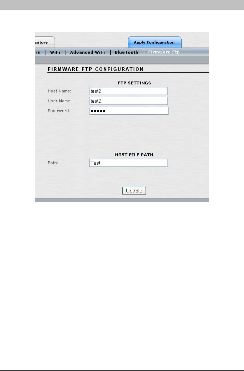
FIRMWARE FTP
This window is where FTP parameters are set at the network level in order for software updates
to be made to the Access/One Network.
• Host Name: FTP server host name.
• User Name: FTP server user name.
• Password: FTP server password.
• Path: Identify any accessible directory for downloading an image.
Note: The downloaded file will always be ‘accessone.bin’ when configured via
Manager/One. If a different file name is required, using the module-level management will
allow another filename to be used.
Click the ‘Update’ button at the bottom of the page to save any changes made to the settings in
this page. Click the ‘Apply Configuration’ tab to make the configuration information active in
the Access/One Network cloud.
30
USER GUIDE
Security
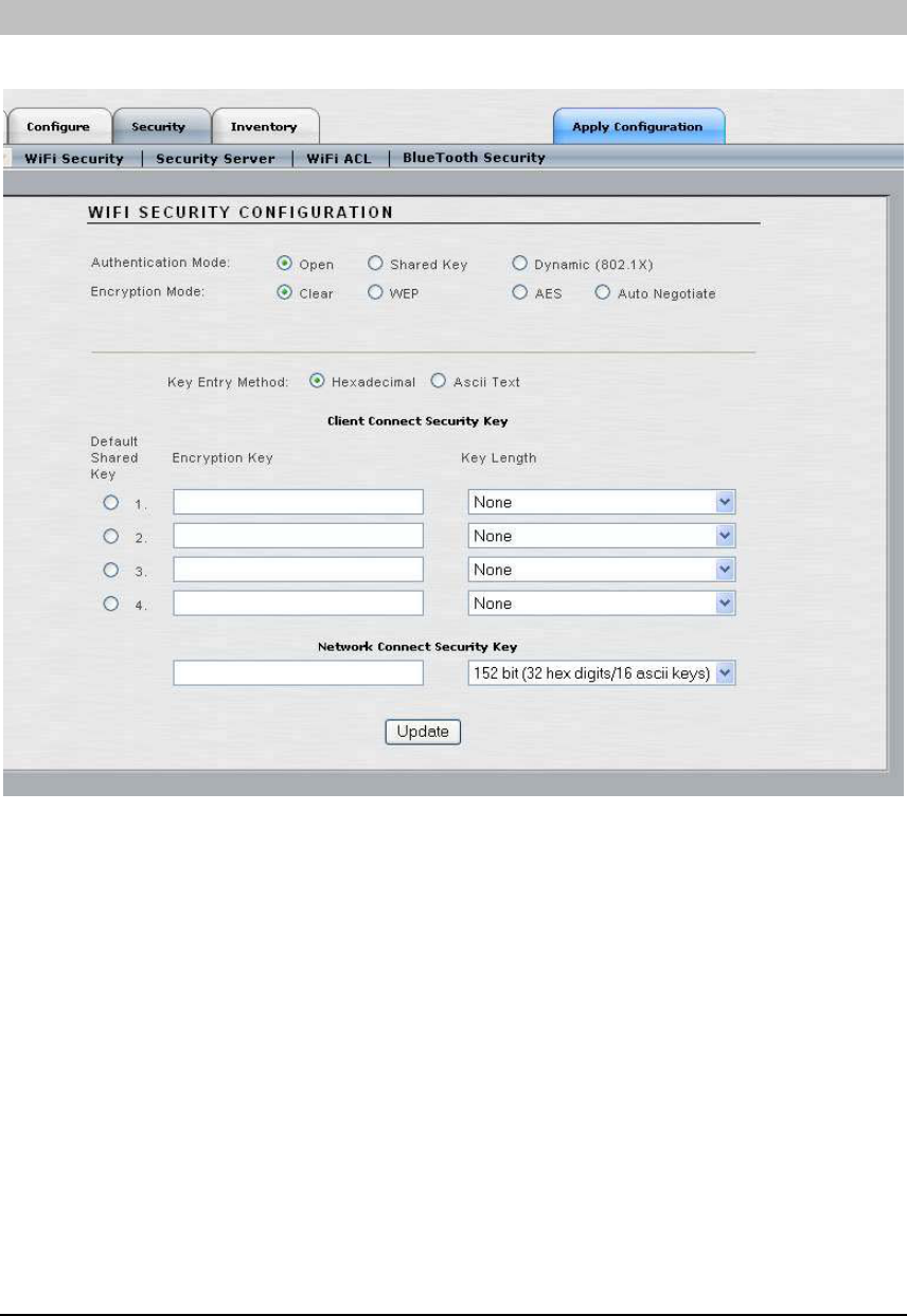
WIFI SECURITY
This window is where Wi-Fi network Security parameters are set for Access/One Network.
• Authentication Mode: This option selects the authentication type that will be used.
o Open: Local authentication.
o Shared Key: A static shard WEP key will be used for authentication. This
option is not recommended since all users will be using the same key.
o Dynamic Key: The authentication server (RADIUS) will give a key to each
user for unicast traffic. Multicast traffic will use the default key. This is the safest
and recommended option. A default shared key must be configured in slots 2, 3
or 4 if dynamic key is selected. See below for more information.
31
USER GUIDE
• Encryption Mode: This option selects the type of encryption used.
o Clear: Available for Open or Dynamic authentication. Messages will be sent
unencrypted between user devices and the Access/One Network Nodes.
o WEP: Wired Equivalency Privacy (WEP) is a security protocol for WLAN. It
encrypts data using an RC4 stream cipher with a seed of 64, 128 or 152 bits.
o AES: Advance Encryption Standard (AES) encrypts data using a symmetric
152 bit data block, and is generally considered the most secure option available.
o Auto Negotiate: The encryption mode will be negotiated in real time between
the participating devices. This allows the simultaneous use of AES and WEP.
Authentication
Type Supported Encryption Types
Open Clear: All users have access
WEP, AES, Auto: Requires static encryption key
Shared WEP: Requires static encryption key (not recommended)
Dynamic
Clear: User must authenticate, but no encryption
WEP, AES, Auto: Key is delivered via authentication server
after authentication.
• Key Entry Mode: Select between hexadecimal and ASCII text.
• Network Connect Security Key: Select which key will serve as the default key to
encrypt packets to be transmitted on a wireless uplink between Nodes. The key
length is fixed at 152 bits. Refer to the next section for more details on this.
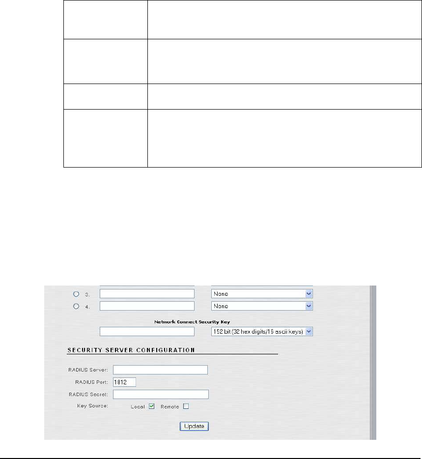
If ‘Dynamic’ key is selected for Authentication Mode, a Security Server Configuration appears:
32

USER GUIDE
The user can enter RADIUS (Remote Authentication Dial In User Service) Server parameters
here or on the next tab (Security Server). For dynamic encryption, the Access/One Network
Nodes communicate with an authentication server to obtain encryption keys to use.
• RADIUS Server: Specify the Host name or IP address of the RADIUS Server.
• RADIUS Port: Specify the RADIUS port number.
• RADIUS Secret: Specify the RADIUS Server’s shared secret. The Network Node will
use this server secret when it forwards authentication credentials to the RADIUS Server.
• Key Source: Specify where the RADIUS keys are located. Selecting ‘Local’ will cause
the Network Node to use the static keys configured in the previous section. If both
checkboxes are selected the Network Node will use the local key unless it receives a key
from the RADIUS Server. If ‘Remote’ is selected, the Network Node will use only keys
from the RADIUS Server.
Click the ‘Update’ button at the bottom of the page to save any changes made to the settings in
this page. Click the ‘Apply Configuration’ tab to make the configuration information active in
the Access/One Network cloud.
WIRELESS UPLINK (NETWORK CONNECT) SECURITY
The Access/One Network provides WEP and AES ciphers for encryption and 802.1x remote
authentication to protect wireless stations associated with each Network Node. The inter-Node
Network Connect wireless uplink is protected with an AES static key to prevent eavesdropping.
The factory configured default key is hidden from view to retain secrecy for a basic network.
However, this key may be changed by using the ‘Network Connect Security Key’ field to allow
each network to have a unique key. If additional security is required, a different Network
Connect Security Key may be provisioned for each Network Connect module. This is done by
creating an Access Control List (ACL) entry in the receiving Node that contains the MAC
address of the Network Connect Node and a specific unique key.
The Network Connect solution for Access/One Network prevents unauthorized wireless
connections from being established to the network by blocking user traffic in two scenarios:
1. If the Network Connect is configured for the default cloud name (AccessOne),
Manager/One forces the Administrator to approve/admit the Network Node to
the cloud before user traffic is bridged to the network.
2. If the two Network Nodes that are wirelessly connected (via the uplink) have
different Network Connect Security Keys configured.
In either instance, the Network Connect is remotely manageable within Manager/One to allow
configuration changes necessary to update the Network Connect parameters. However, if
Network Connect is configured for a new security key, but the receiving Network Node still has
the default security key, remote management will not be possible.
33
USER GUIDE
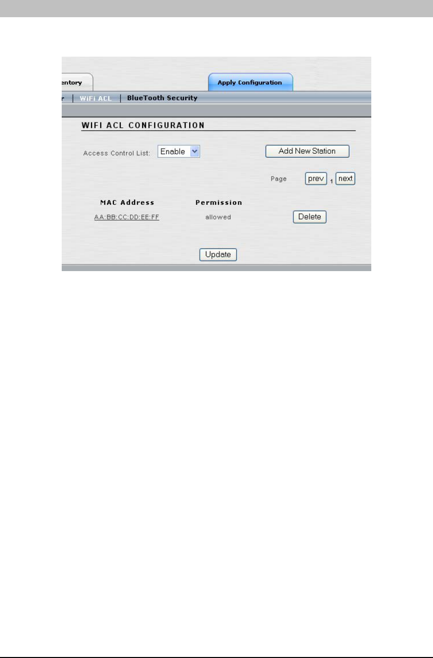
WIFI ACL
This window configures an Access Control List (ACL) determining which user devices (stations)
are allowed to connect to Access/One Network.
• Access Control List: Enables you to enable or deny network access based on the
MAC address of a user device (station).
o Disable: All stations can request association with a Network Node in the
Access/One Network. This means that the ACL will not be checked when a
station attempts to authenticate.
o Enable: Stations are assigned a DENY or ALLOW permission status. If the
MAC address of station trying to gain access is set to DENY, it will not be
allowed to associate with the network. If the MAC address is set to ALLOW, or
not configured in the ACL, the station will be allowed network access.
o Strict: Only stations assigned ALLOW permissions in the ACL will be granted
access to the network, regardless of encryption settings. In addition, if the entry
is configured for an encryption key, the station is also required to match that
key before gaining access. If no ACL entry exists for a MAC address it will not
be allowed to associate with the network. The ACL will accept multiple levels of
authentication (ALLOW, KEY, DENY) concurrently so that stations with or
without encryption (or shared key authentication) can be admitted.
34
USER GUIDE
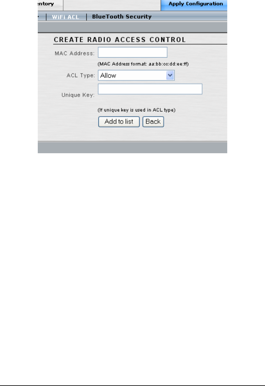
• Click the ‘Add New Station’ button to configure the following:
• MAC Address: Enter the MAC address of a user device/station.
• ACL Type: Select the permission level for this user device/station.
• Unique Key: Optionally, enter a unique key which will be used for unicast messages.
Click the ‘Add to list’ button to add the new user device to the ACL. To remove a user device
from the ACL, click the corresponding ‘Delete’ button (shown in the previous window).
Click the ‘Back’ button when finished adding new user devices/stations.
In the previous window, click the ‘Update’ button at the bottom of the page to save any changes
made to the settings in this page. Click the ‘Apply Configuration’ tab to make the configuration
information active in the Access/One Network cloud.
35
USER GUIDE
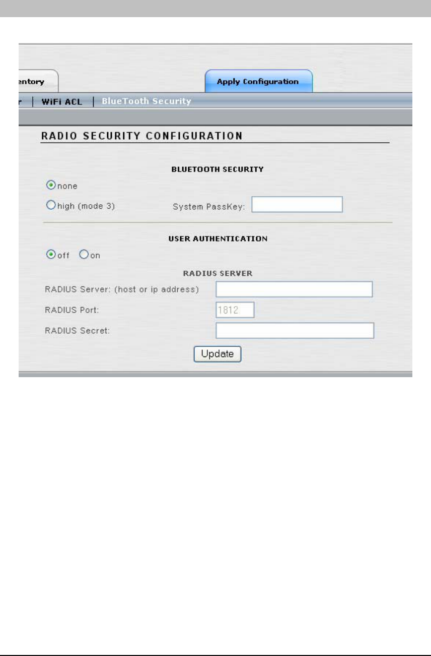
BLUETOOTH SECURITY
This window configures the Bluetooth Security options at the network-level.
• BLUETOOTH SECURITY: Select ‘none’ if you want the Bluetooth Modules to
accept connections from any Bluetooth-enabled mobile device. Select ‘high (mode 3)’ if
you want to enforce link-level Bluetooth security on Access/One Network.
• System PassKey: If you selected ‘high’ Bluetooth security in the previous step, you
must enter a System PassKey. The passkey is the equivalent of a shared encryption key.
It is used to initially authenticate the Bluetooth device with the Access/One Network
Bluetooth Module. It may also be used to provide encryption services.
Note: Link-level security is enforced at the same level for all applications; it is established at
connection setup.
36

USER GUIDE
• USER AUTHENTICATION: Select ‘on’ or ‘off’ to enable or disable user
authentication. When enabled (on) all users are required to enter a user name and
password to authenticate.
RADIUS Server parameters can be set via this window. If these parameters were previously set
in the WiFi Security screen, then they will automatically be displayed here and do not need to be
reentered. However, if these parameters have not been previously set, in case of a pure
Bluetooth network, the fields will be empty and the RADIUS setting can be set here.
RADIUS is used in the Bluetooth environment to authenticate a user name and password when
USER AUTHENTICATION is set to ‘on’ (described above). There may be a need to use a
different RADIUS server for Bluetooth versus Wi-Fi, depending on the capability of the
RADIUS server being used. The Access/One Network 802.11 Modules communicate with the
RADIUS Server using EAP encapsulation, while the Bluetooth Module requires non-EAP
communications. If both of these settings cannot be supported from the same RADIUS server,
the Bluetooth network will require a different RADIUS server to be used. Any RADIUS Server
entries made on this screen will only be applied to the Bluetooth network settings.
• RADIUS Server: Enter the host name or IP address of the RADIUS Server.
• RADIUS Port: Enter the RADIUS Server port number.
• RADIUS Secret: Enter the RADIUS Server shared secret. The Network Node will use
this shared secret when it forwards authentication credentials to the RADIUS Server.
Click the ‘Update’ button at the bottom of the page to save any changes made to the settings in
this page. Click the ‘Apply Configuration’ tab to make the configuration information active in
the Access/One Network cloud.
37
USER GUIDE
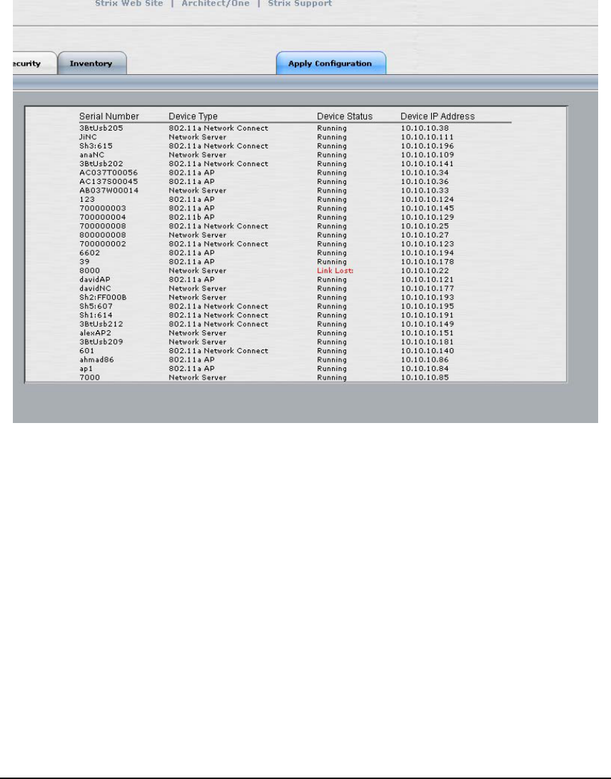
T
Invento
his tab provides administrator with an inventory view of the Access/One Network.
The inventory list consists of Module serial numbers, Module types, Module status and
IP addresses assigned.
ry
T
Apply C
his tab is used to apply any changes that have been made at either the network (cloud)
or subnet (sub-cloud) level. Once this tab has been clicked, the changes are propagated
and applied to all Network Nodes and modules within the Access/One Network.
onfiguration
38
USER GUIDE
Appendix 1: Module / Device Management
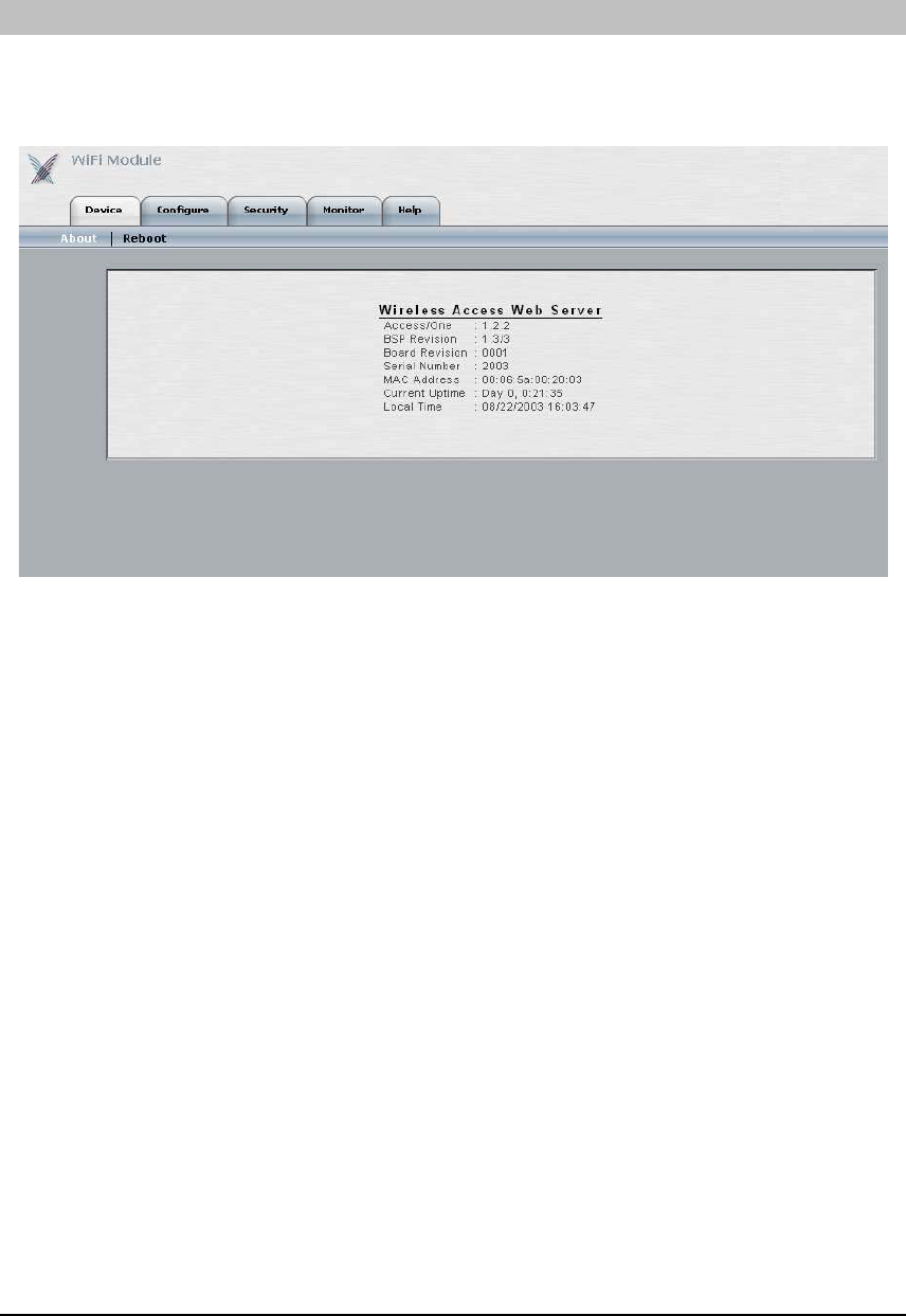
DEVICE
The ‘Device’ tab has two submenu items. The ‘About’ submenu provides information about the
selected module, such as code version, serial number, MAC address, etc. The ‘Reboot’ submenu
is used when a reboot needs to be performed on just this module, and is immediate.
39
USER GUIDE
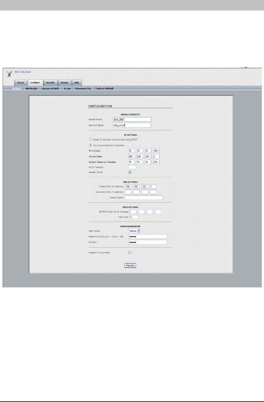
CONFIGURE
The ‘Configure’ tab enables the module-level configuration to be performed. Click the ‘Update’
button at the bottom of the page for any changes to be saved. A ‘Reboot’ button will appear
after clicking ‘Update’ as it is necessary to reboot the module after changes are made.
The ‘Module’ submenu (shown below) is used to configure basic module-level details, such as
name, network assignment, static IP address, static DNS and management password.
40
USER GUIDE
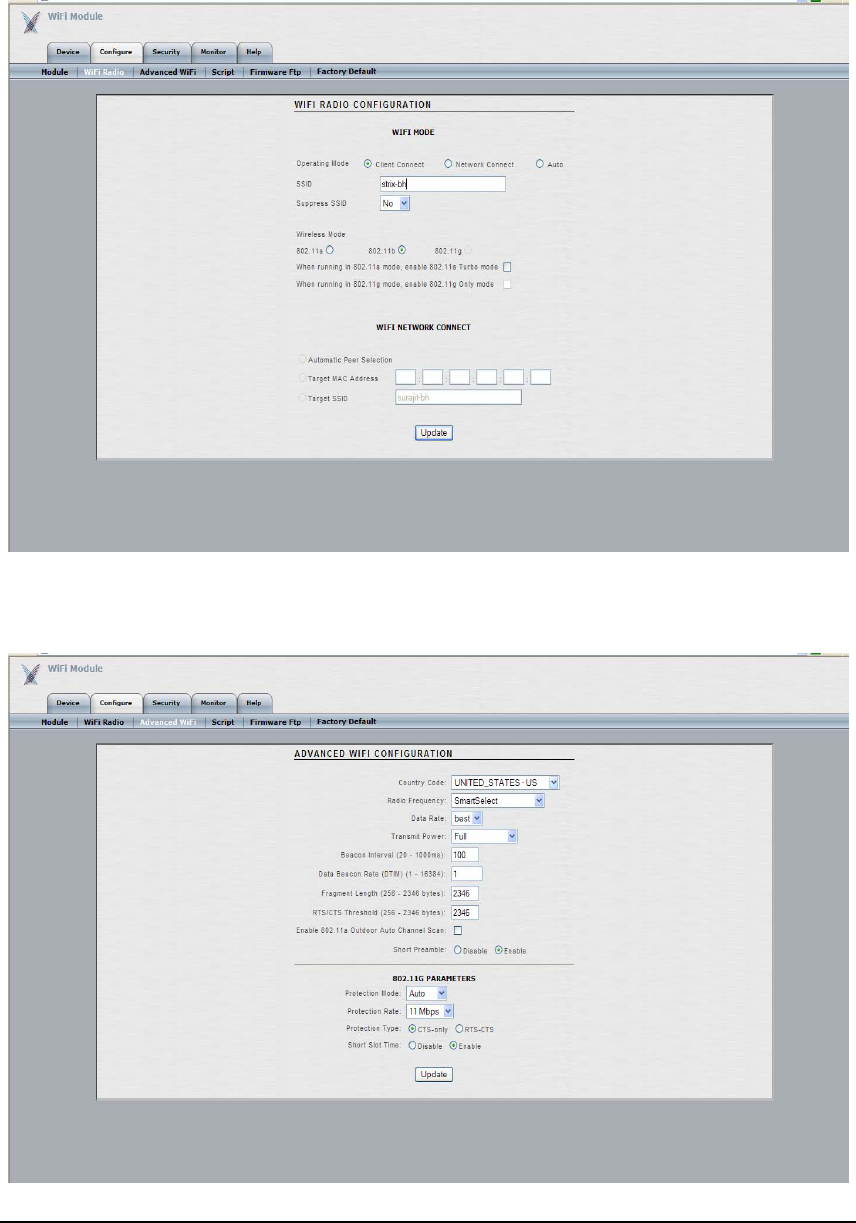
The ‘WiFi Radio’ submenu (shown below) is used to configure module-level Wi-Fi settings,
such as module role (Client Connect, Network Connect), SSID, RF type, etc.
The ‘Advanced WiFi’ submenu (shown below) is used to configure advanced module-level Wi-
Fi settings, such as country code, data rate, transmit power, etc.
41
USER GUIDE
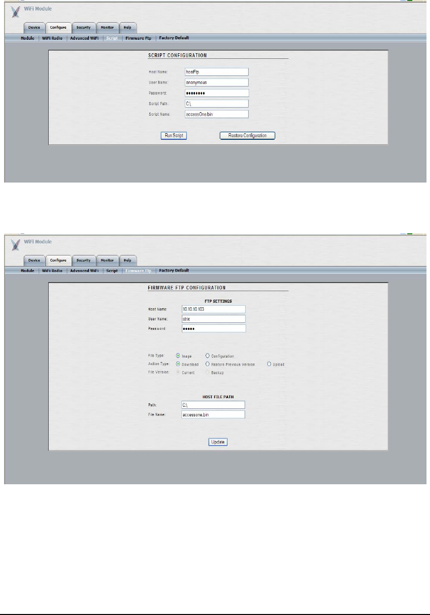
The ‘Script’ submenu (shown below) is used to configure an individual module with a text
script.
The ‘Firmware FTP’ submenu (shown below) is used to configure module-level FTP settings,
such as host name, user name, password, file path, file name, etc.
42
USER GUIDE
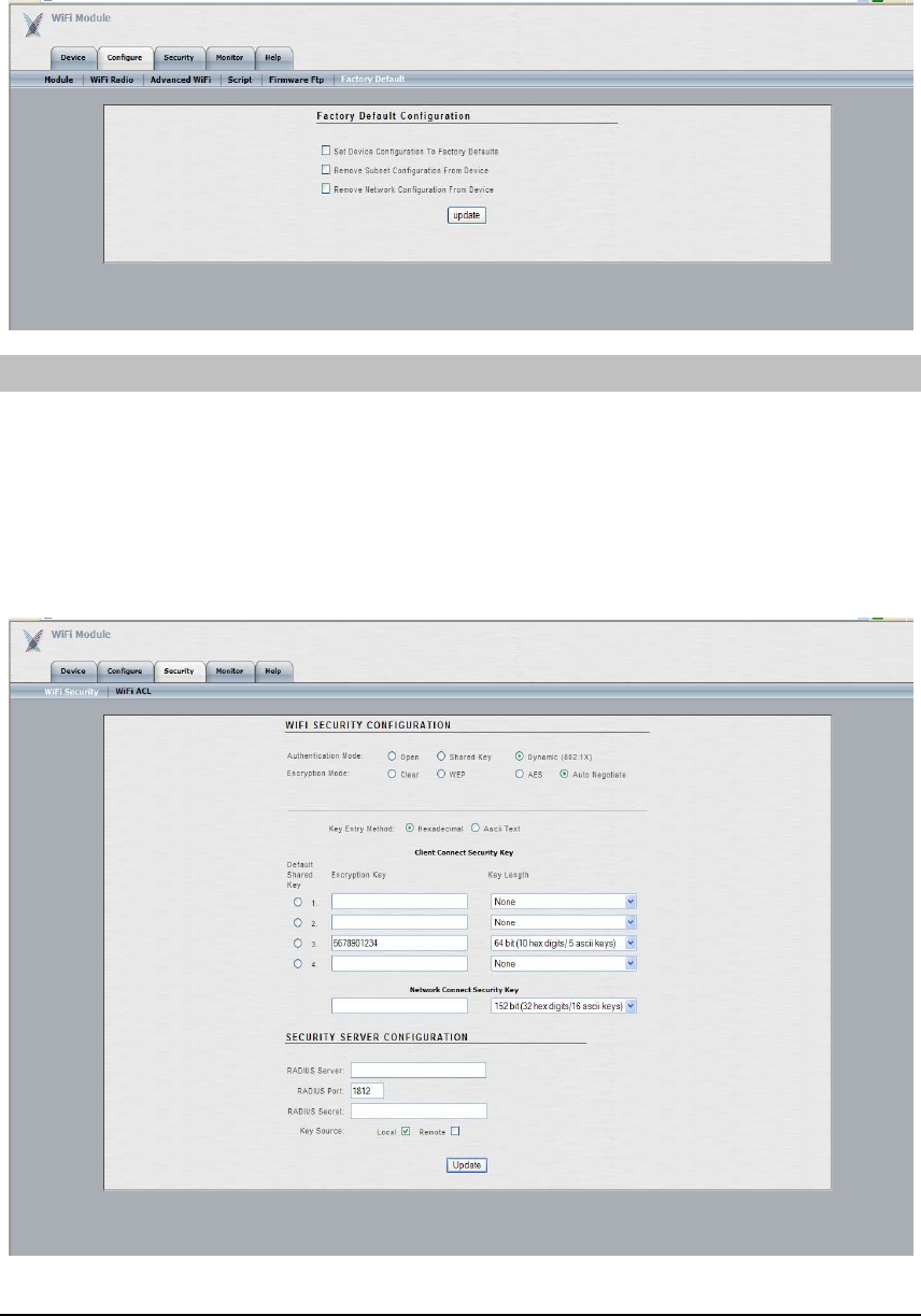
The ‘Factory Default’ submenu (shown below) is used to reset the module back to its factory
default configuration.
SECURITY
The ‘Security’ tab enables the module-level security configuration to be performed. Click the
‘Update’ button at the bottom of the page for any changes to be saved. A ‘Reboot’ button will
appear after clicking ‘Update’ as it is necessary to reboot the module after changes are made.
The ‘WiFi Security’ submenu (shown below) is used to configure module-level Wi-Fi security
settings, such as authentication type, encryption type, static security keys, RADIUS Server
parameters, etc.
43
USER GUIDE
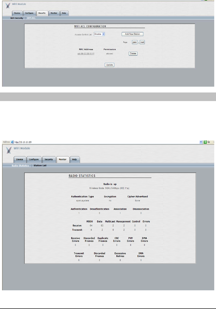
The ‘WiFi ACL’ submenu (shown below) is used to configure module-level Wi-Fi Access
Control List (ACL) settings, such as ACL mode, add/remove stations, etc.
MONITOR
The ‘Monitor’ tab provides module-level monitoring functions.
The ‘Radio Statistics’ submenu (shown below) is used to view module-level details and statistics,
such as status, authentication / deauthentication / association / disassociation attempts,
receive/transmit packet statistics, error statistics, etc.
44
USER GUIDE
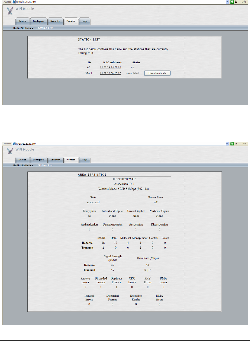
The ‘Station List’ submenu (shown below) is used to view a list of devices/stations that are
attached to the specific module being managed. Each station’s ID, MAC address and state are
provided. Any station’s MAC address can be clicked on for more detailed statistics summary for
that station.
Once a MAC address is clicked, a window like the one the below is shown which displays
station-level details and statistics, such as status, authentication / deauthentication / association
/ disassociation attempts, receive/transmit packet statistics, error statistics, etc.
45

T
Appen
His chapter lists the basic protocols and features supported by the Access/One
Network and its Network Nodes. It also includes the environmental and regulatory
characteristics of the hardware. For more up-to-date information, please refer to the
Strix Access/One Network data sheets.
dix 2: Specifications
PHYSICAL ATTRIBUTES
Module Description User Interfaces Size
BME0 Base Module with no RJ-45 18V DC input 5.0” x 3.65” x 1.30”
BME1 Base Module with one RJ-45 18V DC input
Qty 1 RJ-45 w/ PoE 5.0” x 3.65” x 1.30”
BME4 Base Module with four RJ-45 18V DC input
Qty 4 RJ-45, incl. PoE 5.0” x 3.65” x 1.30”
WM11A 802.11a Wireless Module Qty 2 Reverse SMA 5.0” x 3.65” x 0.60”
WM11B 802.11b Wireless Module Qty 2 Reverse SMA 5.0” x 3.65” x 0.60”
WM11G 802.11g Wireless Module Qty 2 Reverse SMA 5.0” x 3.65” x 0.60”
WMBT Bluetooth Wireless Module N/A 5.0” x 3.65” x 2.50”
AM11AABG 802.11a & a/b/g Antenna Module N/A 5.0” x 3.65” x 1.25”
NWSV Network Server Module N/A 5.0” x 3.65” x 0.60”
EMISSIONS AND SAFETY STANDARDS
The Access/One Network complies with standard qualifications for North America, Canada,
the European Union, and many Asia Pacific countries. These qualifications include:
EN 55022:1998 + A1:2000, EN 55024:1998 + A1:2001, IEC 60950 3rd Ed.:1999 / EN
60950:2000, EN 300328-1:2001, ETS 300328-2:2001, EN 301489-1:2000, EN 301489-
17:2002, and EN 301893:2002.
46

USER COVERAGE RANGES FOR BLUETOOTH, 802.11A, 802.11B, & 802.11G
Exact range calculations for each of the technologies cannot be provided as many factors impact
the range and coverage area. These factors include; physical environment configuration,
interfering factors (such as walls, cubicles, desks, elevators, etc), and use of external versus
internal antennas, to name just a few. The Strix Architect/One application will enable users to
understand what ranges to expect based on their exact deployment environment. In
performance benchmarking against competitive products the Strix solution met or exceeded our
primary competitor’s range. Following is a table that provides general information regarding
what types of ranges should be expected for the various wireless technologies supported by the
Access/One Network.
802.11a 802.11b 802.11g Bluetooth
Indoor:
60 ft (18m) @ 54Mbps
170 ft (50m) @ 6Mbps
Outdoor:
100 ft (30m) @ 54Mbps
1000 ft (300m) @ 6Mbps
Indoor:
150 ft (45m) @ 11Mbps
400 ft (120m) @ 1Mbps
Outdoor:
800 ft (240m) @ 11Mbps
2000 ft (600m) @ 1Mbps
Indoor:
60 ft (18m) @ 54Mbps
170 ft (50m) @ 6Mbps
Outdoor:
100 ft (30m) @ 54Mbps
1000 ft (300m) @ 6Mbps
Indoor
165 feet (50m) @ 100Kbps
47

T
Appen
his chapter lists the Command Line Interface (CLI) commands available through every
Access/One Network module. A Telnet session can be started by ‘right-clicking’ on the
module displayed in the Manager/One window of your browser. The term ‘cloud’ used
in the commands is refers to the Access/One Network as a whole, while ‘sub-cloud’
denotes an IP subnet or other arbitrary grouping of the Access/One Network Nodes.
dix 3: CLI Commands
bc shownodes - Show nodes in cloud
bc showdevices - Show devices in cloud
bc sendcfg cloud - Send cloud configuration
bc sendcfg subcloud <id> - Send sub-cloud
bc imageload cloud - Load image on cloud
bc imageload subcloud <id> - Load image on sub-cloud
bc pagerenable cloud - Set pager on for cloud
bc pagerenable subcloud <id> - Set pager on for sub-cloud
bc pagerdisable cloud - Set pager off for cloud
bc pagerdisable subcloud <id> - Set pager off for sub-cloud
bc reboot cloud - Reboot cloud
bc reboot subcloud <id> - Reboot sub-cloud
bc setview cloud - Cloud view
bc setview subcloud <id> - Sub-cloud view
bc setview device <ipaddr> - Device view
bc include all - Include all devices
bc include devices <ipaddr> - Include specified devices
bc exclude all - Exclude all devices
bc exclude devices <ipaddr> - Exclude specified devices
bc changestname <ipaddr> <name> - Change station name
bc help - Batch configuration help
48

ftransfer params set … - Set ftp parameters
hostname <hostname>
username <username>
password <password>
path <path>
filename <remotefile>
ftransfer params get - Get ftp parameters
ftransfer download image <remotefile> - Download image file
ftransfer download configuration <remotefile> - Download configuration file
ftransfer restore image - Restore previous image
ftransfer restore configuration - Restore previous configuration
ftransfer upload image current <remotefile> - Upload current image
ftransfer upload image backup <remotefile> - Upload backup image
ftransfer upload configuration current <remotefile> - Upload current configuration
ftransfer upload configuration backup <remotefile> - Upload backup configuration
ftransfer help - File transfer help
get cims - Display Cloud structure
get config - Display System Configuration
get dhcp mode - Display DHCP mode
get domainsuffix - Display Domain Name Server suffix
get fan - Display the fan status
get gateway - Display Gateway IP Address
get hardware - Display Hardware Revisions
get hostipaddr - Display Host IP Address
get ipaddr - Display IP Address
49

get ipmask - Display IP Subnet Mask
get login - Display Login User Name
get nameaddr - Display IP address of name server
get cloudname - Display Cloud Name
get subcloudname - Display Subcloud Name
get stackid - Display Stack Id
get outdoorenviron - Display outdoor environment
get radiusname - Display RADIUS server name or IP
address
get radiusport - Display RADIUS port number
get snmp - Display SNMP Community Name
get sntpserver - Display SNTP/NTP Server IP
address
get syslog settings - Get syslog configuration settings
get syslog consoledump - Dump syslog console buffer contents
get syslog filedump - Dump syslog file contents
get syslog help - Syslog get help
get system - Display System Name
get telnet - Display Telnet Mode
get temperature - Display ambient temperature
get timeout - Display Telnet Timeout
get tzone - Display Time Zone Settin
get uptime - Display UpTime
get voltage - Display the voltage sources
help - Display CLI Command List
ping - Ping
50

quit - Logoff
rawftp - Software update via FTP
reboot - Reboot Access/One
remotenc add - Add remote network server IP
address
remotenc remove - Remove remote network server IP
address
remotenc show - Show remote network server IP
address
run - Run command file
set cloudname - Set cloud name
set dhcp disable - Disable DHCP
set dhcp enable - Enable DHCP
set domainsuffix - Set Domain Name Server suffix
set factorydefault - Restore to default factory settings
set snmp getcmnty - Set SNMP community
set snmp setcmnty - Get SNMP community
set gateway - Set Gateway IP address
set hostipaddr - Set Host IP address
set ipaddr - Set IP address
set ipmask - Set IP subnet mask
set login - Modify Login user name
set nameaddress primary - Set primary name server IP address
set nameaddress secondary - Set secondary name server IP address
set outdoorenviron disable - Disable outdoor environment
set outdoorenviron enable - Enable outdoor environment
51

set pager off - Module LED returns to current state
set pager on - Module LED repeats Red, Green,
Orange sequence
set password - Modify Password
set radiusname - Set RADIUS name or IP address
set radiusport - Set RADIUS port number
set radiussecret - Set RADIUS shared secret
set sntpserver - Set SNTP/NTP Server IP Address
set syslog server - Syslog server configuration
set syslog console - Syslog console configuration
set syslog file - Syslog file configuration
set syslog help - Syslog set help
set system name - Set System Name
set system contact - Set System Contact
set system location - Set System Location
set telnet disable - Disable Telnet access
set telnet enable - Enable Telnet access
set timeout - Set Telnet timeout
set tzone - Set time zone setting
timeofday - Display current time of day
version - Software version
52

bc shownodes
bc showdevices
bc sendcfg cloud
bc sendcfg subcloud <id>
bc imageload cloud
bc imageload subcloud <id>
bc pagerenable cloud
bc pagerenable subcloud <id>
bc pagerdisable cloud
bc pagerdisable subcloud <id>
bc reboot cloud
bc reboot subcloud <id>
bc setview cloud
bc setview subcloud <id>
bc setview device <ipaddr>
bc include all
bc include devices <ipaddr>
bc exclude all
bc exclude devices <ipaddr>
bc changestname <ipaddr> <name>
bc help
ftransfer params set …
hostname <hostname>
username <username>
password <password>
path <path>
filename <remotefile>
ftransfer params get
ftransfer download image <remotefile>
ftransfer download configuration
<remotefile>
ftransfer restore image
ftransfer restore configuration
ftransfer upload image current
<remotefile>
ftransfer upload image backup
<remotefile>ftransfer upload
configuration current <remotefile>
ftransfer upload configuration backup
<remotefile>
ftransfer help
get cims
-Show nodes in cloud
-Show devices in cloud
-Send cloud configuration
-Send sub-cloud
-Load image on cloud
-Load image on sub-cloud
-Set pager on for cloud
-Set pager on for sub-cloud
-Set pager off for cloud
-Set pager off for sub-cloud
-Reboot cloud
-Reboot sub-cloud
-Cloud view
-Sub-cloud view
-Device view
-Include all devices
-Include specified devices
-Exclude all devices
-Exclude specified devices
-Change station name
-Batch configuration help
-Set ftp parameters
-Get ftp parameters
-Download image file
-Download configuration file
-Restore previous image
-Restore previous configuration
-Upload current image
-Upload backup image
-Upload current configuration
-Upload backup configuration
-File transfer help
-Display Cloud structure
get config
get dhcp mode
get domainsuffix
get fan
get gateway
get hardware
get hostipaddr
get ipaddr
get ipmask
get login
get nameaddr
get cloudname
get subcloudname
get stackid
get outdoorenviron
get radiusname
get radiusport
get snmp
get sntpserver
get syslog settings
get syslog consoledump
get syslog filedump
get syslog help
get system
get telnet
get temperature
get timeout
get tzone
get uptime
get voltage
help
ping
quit
rawftp
reboot
remotenc add
remotenc remove
remotenc show
run
set cloudname
set dhcp disable
set dhcp enable
- Display Current System Configuration
- Display DHCP mode
- Display Domain Name Server suffix
- Display the fan status
- Display Gateway IP Address
- Display Hardware Revisions
-Display Host IP Address
- Display IP Address
- Display IP Subnet Mask
- Display Login User Name
- Display IP address of name server
- Display Cloud Name
- Display Subcloud Name
- Display Stack Id
- Display outdoor environment
- Display RADIUS server name or IP address
- Display RADIUS port number
- Display SNMP Community Name
- Display SNTP/NTP Server IP address
- Get syslog configuration settings
- Dump syslog console buffer contents
- Dump syslog file contents
- Syslog get help
- Display System Name
- Display Telnet Mode
- Display the unit's ambient temperature
- Display Telnet Timeout
- Display Time Zone Settin
- Display UpTime
- Display the voltage sources
- Display CLI Command List
- Ping
- Logoff
- Software update via FTP
- Reboot Access/One
-Add remote network server IP address
-Remove remote network server IP address
-Show remote network server IP address
-Run command file
-Set cloud name
-Disable DHCP
-Enable DHCP
set domainsuffix
set factorydefault
set snmp getcmnty
set snmp setcmnty
set gateway
set hostipaddr
set ipaddr
set ipmask
set login
set nameaddress
primary
set nameaddress
secondary
set outdoorenviron
disable
set outdoorenviron
enable
set pager off
set pager on
set password
set radiusname
set radiusport
set radiussecret
set sntpserver
set syslog server
set syslog console
set syslog file
set syslog help
set system name
set system contact
set system location
set telnet disable
set telnet enable
set timeout
set tzone
timeofday
version
-Set Domain Name Server suffix
-Restore to default factory settings
-Set SNMP community
-Get SNMP community
-Set Gateway IP address
-Set Host IP address
-Set IP address
-Set IP subnet mask
-Modify Login user name
-Set primary name server IP address
-Set secondary name server IP address
-Disable outdoor environment
-Enable outdoor environment
-Module LED returns to current state
- Module LED repeats Red, Green,
Orange sequence
- Modify Password
- Set RADIUS name or IP address
- Set RADIUS port number
- Set RADIUS shared secret
- Set SNTP/NTP Server IP Address
- Syslog server configuration
- Syslog console configuration
- Syslog file configuration
- Syslog set help
- Set System Name
- Set System Contact
- Set System Location
- Disable Telnet access
- Enable Telnet access
- Set Telnet timeout
- Set time zone setting
- Display current time of day
- Software version
53

Appendix 4: Frequently Asked Questions
NETWORK ELEMENTS
Q- What are the elements that make up the Strix Systems product?
A- Access/One Network is a modular system with several categories of building blocks
that perform specific roles within the system. These categories are Client Connect,
Network Connect, Wireless Workgroup, and Network Server.
Each of these categories contains a choice of modules which are individually selected
and assembled to form a single network element called a Network Node. Each
Network Node provides localized connectivity and intelligence with multiple Network
Nodes connected in a mesh to form the Access/One Network.
Q- What are all the possible combinations of modules?
A- Due to the modular architecture of Access/One Network, there are a large number of
possible combinations of modules. Each Network Node within the Access/One
Network is assembled based on the categories defined above.
Each Network Node can be assembled to provide a single or dual RF technology for
Client Connection (802.11a, b, g, or Bluetooth), with wired or wireless Network
Connectivity, and with or without a Network Server. Stationary users can also be added
to the Access/One Network via the Wireless Workgroup.
There are some basic physical configuration rules for each Network Node as they are
being assembled, which are outlined below.
• The Base Module must always be the lowest module within the Node
• When using 802.11a Network Connect, the 802.11a Wireless Module must be
placed as the lowest Wireless Module within the Node.
• When used, the External Antenna Adapter Module must be placed immediately
above its associated Wireless Module within the Node.
• The 802.11 Antenna Modules must be placed above all other modules within
the Node (must be the topmost module in the Node).
• The Bluetooth Module must be placed above all other modules within the
Node (must be the topmost module in the Node).
Q- What are the prohibited combinations?
A- Besides the physical assembly rules defined above, it is prohibited to use more than
three ‘active’ modules within any single Network Node. An ‘active’ module is defined as
being either a Wireless Module or a Network Server Module. Base Modules and
Antenna Modules are not considered ‘active.’
54

PRODUCT ASSEMBLY AND SETUP
Q- What order should I assemble the modules out of the box?
A- All Access/One Network Nodes are shipped as unassembled modules in a single box.
The modules are arranged in the box in the order they should be stacked to form a
Network Node. However, the user should not assume that this is always the case as
some boxes may have been opened by customs, for example, and the modules could be
rearranged. The following is an 8-step general guideline you should follow when that
will work for any combination of Access/One Network modules. Not all steps will
apply to all Nodes, so you should only perform the steps if you have the module
mentioned. If you don’t have the module mentioned, skip and go to the next step.
Step 1: Begin with the Base Module (marked BMEx) which is placed on the bottom of
the module stack (Node). This is a step is an absolute requirement for ALL Nodes.
Step 2: If you have Network Server Module (NWSV), place it immediately on top of the
Base Module (Step 1). If you don’t have an NWSV, go to step 3.
Step 3: If you have a WM11A Module, this is placed next on the module stack. If you
don’t have a WM11A, go to Step 5.
Step 4: If you have a second WM11A Module, this is placed next on the module stack.
If you don’t have a second WM11A, go to Step 5.
Step 5: If you have a WM11G Module, this is placed next on the module stack. If you
don’t have a WM11G, go to Step 6.
Step 6: If you have a WM11B Module, this is placed next on the module stack. If you
don’t have a WM11G, go to Step 7.
Step 7: If you have a Bluetooth Module (WMBT) it must be the top-most module in the
Node (module stack). If you have a WMBT and also either a WM11G or WM11B
below it, you will also need to connect an External Antenna Module (AMEA) so that an
external antenna can be used. If you have a WMBT your Node is now complete and
ready for use. If you did not have a WMBT, go to the step 8.
Step 8: Connect the Antenna Module (AM11x) as the final module on top of the Node
(module stack). Your Node is now complete and ready for use.
55

Q- Which modules can be used for wireless Network Connect.
A- Both the WM11A and WM11G Wireless Modules can function as either Network
Connect (wireless uplink) or a Client Connect (for user connectivity). The exact
function of a WM11A or WM11G Module is determined automatically by the
Access/One Network based on needs of the Node. If a 10/100 Ethernet cable is not
plugged-in to the Base Module of the Node, one of the Wireless Modules in the Node
must function as a Network Connect. If there is more than one Wireless Module in the
Node, the bottom (lowest) Module will act as the Network Connect. In a correctly
configured Node (as described in the 8-step process above) this Module will be either a
WM11A or a WM11G Wireless Module.
Q- How do I setup a wireless Network Connect on a Network Node that does not
have an Ethernet cable connection?
A- Nothing. In the absence of an Ethernet cable connection, the Node will automatically
configure the lowest Wireless Module to act as a Network Connect during the intra-
Node discovery process.
Q- Do I need to power-up the Network Nodes in any particular order to enable the
wireless Network Connect function correctly?
A- No. The order in which you power up the Network Nodes is irrelevant to setting up the
network. After the Intra-Node discovery process has been completed, the Nodes will
start the inter-Node discovery. This process will take several minutes after all the Nodes
are powered-up and their LEDs are solid green.
Q- What do I need to do to manage the newly setup Access/One Network?
A- Follow the instructions in this User Guide that start on Page 2, by downloading and
installing the Manager/One plug-in. The same section describes in detail how to
reconfigure each Node. You will need to use a PC residing on the same subnet as the
Access/One Network, and you will have to use Internet Explorer 6.0 with the
Manager/One plug-in to do this.
56

PRODUCT PERFORMANCE
Q- What bandwidth can I expect?
A- Actual data throughput is approximately one-half the link rate at these ranges for 802.11
technology, which is standard for these types of products. Bluetooth throughput is
relatively consistent across the supported range.
Q- What Bluetooth profile(s) do you implement?
A- The LAN Access Profile is the first Bluetooth profile that is supported for the initial
Access/One Network release. The product architecture does allow for other Bluetooth
profiles to be supported, so as the need for support of other profiles is determined the
implementation will involve some level of development and testing effort.
Q- What Bluetooth devices may be used on an Access/One Network?
A- Any Bluetooth device that supports the Bluetooth SIG v1.1 standard with LAN Access
Profile.
Q- How many Network Server Modules do I need?
A- A single Network Server is needed for every eight (8) Network Nodes in the
Access/One Network, regardless of the RF technology is being used (802.11 or
Bluetooth). This rule applies whether the Network Nodes communicate with the
Network Server via wired Ethernet or wireless 802.11a. For traffic the Ethernet rule-of-
thumb applies: while Each Node can support up to 256 users per RF technology, for
optimal throughput target 20 users per RF per Node.
SYSTEM SOFTWARE AND OPERATION
Q- Describe the features in a Network Server.
A- The main features within the Network Server fall into three categories, discovery,
management and security.
The discovery category of features enables the Access/One Network elements to
automatically link themselves together enabling secure, reliable performance and
allowing IT administrators to install Network Nodes with minimal effort. The discovery
category also provides for complete user mobility within the Access/One Network.
There are two types of discovery mechanism within the Access/One Network:
infrastructure and user. Infrastructure discovery involves Access/One Network
automatic network construction, as well as self-healing. User discovery involves new
user authorization and mobility.
57

The management category of features provides the tools and facilities to monitor,
diagnose, configure, meter usage, and extend Access/One Network services so that
administration of the wireless network is minimal (occurs automatically), intuitive,
flexible and secure. These tools include configuration management, usage metering and
SNMP monitoring.
The security category of features protects the customer’s internal network resources
from unauthorized access through the Access/One Network, providing privacy for
wireless communications and mitigating the risk of denial-of-service and other similar
attacks.
Q- Describe the “Active Discovery” process and how it works.
A- When a Network Node is turned on in an Access/One Network the individual modules
within the Node automatically discover each other and determine their physical position
and role within the Node, including whether the interface to the network is wired or
wireless.
The Network Node then automatically discovers the rest of the Nodes in the
Access/One Network via the wired or wireless Network Connect. The Node
automatically associates with one Network Server using an algorithm based on several
decision factors. The selected Network Server then provides a list of known network
elements across all subnets to the Node, as well as information such as connected
devices, wireless channels in use, etc.
In addition to this process, as Network Servers become aware of each other they
communicate and synchronize known element tables to provide failure redundancy,
while tracking users in order to provide mobility as they move around the network.
Q- How does the Access/One Network prevent bridge loops?
A- The Network Connect function of the Access/One Network contains a proprietary
algorithm which prevents the association to Network Nodes which are also known on
the Ethernet network. For instance, if a Network Connect was accidentally plugged
directly into the host LAN, it would detect that the Network Nodes were also reachable
via the same Ethernet LAN and automatically shutdown the wireless uplink connection.
This will not prevent traffic from a co-located Network Node from being bridged;
rather it would go directly to the Ethernet LAN. Removing the loop will allow the
Network Connect to re-establish a wireless connection to the Network Nodes.
58

SECURITY
Q- What are the security features and the default security settings?
A- The Access/One Network supports standards-based security features for each radio
technology, as defined in the below table:
802.11a 802.11b 802.11g Bluetooth
Encryption
• WEP (40/128-bit)
• Dynamic WEP
• WPA & TKIP*
• AES
• 802.11i*
Authentication
• 802.1x
Encryption
• WEP (40/128-bit)
• Dynamic WEP
• WPA & TKIP*
• AES
• 802.11i*
Authentication
• 802.1x
Encryption
• WEP (40/128-bit)
• Dynamic WEP
• WPA & TKIP*
• AES
• 802.11i*
Authentication
• 802.1x
Security Mode 1
(non-secure)
Security Mode 2
(service level)
Security Mode 3
(link level)
* Available as a software upgrade in 2H03
These security features provide various options to prevent access to the wireless
network by unauthorized devices. In addition, the Access/One Network contains a
RADIUS client that can interface with a RADIUS network server for user-level
authentication (i.e. by providing a unique username and password). This is an important
extra level of security for customers that are concerned that device-level security is not
enough.
In addition, Access/One Network provides an additional level of system security that is
not present in other wireless networking solutions. When using an 802.11a wireless
Network Connect, the wireless link has AES encryption enabled by default. This
security does not normally exist, as standard wireless networking equipment does
nothing to secure the 10/100 Ethernet connection back to the network.
Q- Where does the RADIUS client reside?
A- There is a RADIUS client within each Access/One Network Wireless Module and the
Network Server.
Q- What authorization databases do you support?
A- The Access/One Network system supports the RADIUS authorization database.
59

SYSTEM MANAGEMENT
Q- Is your system SNMP-manageable? From what platforms?
A- Each Access/One Network Wireless Module and Network Server contains an SNMP
Agent that allows them to be managed by any Network Management Platform via
standard MIB variables and Strix’ private MIB extensions. An example of typical
Management Platform is HP OpenView.
Q- Describe the management GUI. What are the statistics that one may gather
from the system?
A- The Access/One Network can be configured and monitored via Manager/One™, the
system’s built-in web server interface, via a standard web browser. Access/One
Network can also be managed from a terminal or PC connected via Telnet using the
system’s Command Line Interface (CLI).
The main Manager/One screen provides a map (via auto-discovery) of all Network
Nodes within the Access/One Network. From this screen the IT Manager can define
settings such as security on a network-wide, group-level or individual Node basis. This
screen will also provide quick glance details of the Nodes such as health status. The IT
Manager can also click on any Node and drill-down for element manager-type
functionality, such as Node-level configuration and statistics.
The configuration function consists of items such as general and advanced parameters,
security and privacy settings, firmware updates, and SNMP configuration. As you would
expect, from these screens all of the standard networking and wireless parameters can
be defined and set. Examples include SSID, Turbo on/off, DHCP/static IP,
Encryption on/off, WEP/TKIP/AES, Encryption key and length, 802.1x enable, and
RADIUS setup.
The reported statistics are separated by Network Node versus attached stations. The
Network Node statistics reported include total authentication and association attempts,
number of packets sent and received, various transmit / receive errors, and CRC errors.
The per-station statistics monitored and reported include association state, signal
strength, data rate (Mbps), various types of packet errors, authentication type,
encryption, number of associations / disassociations / reassociations, and number of
packets sent and received.
60

INSTALLATION CONSIDERATIONS
Q- How do I mount Strix Network Nodes and Network Servers?
A- There are several mounting options for the Access/One Network. The system is
designed to be placed on a desktop, an office cubicle or the wall/ceiling. As a desktop
or cubicle product, the Access/One Network Node has no specific mounting
requirements and it simply rests on the unit’s rubber feet. Mounting brackets are
available from Strix for the Network Node to be attached to a wall or the ceiling. Note:
When used with the wall/ceiling mounting bracket the Node is physically positioned
upside down for optimal wireless coverage. Also, the Network Node can be placed
above the ceiling tiles, but does require that the unit either be mounted upside down or
used with an appropriately positioned external antenna (i.e. ceiling mounted to provide
adequate wireless coverage for users below).
Q- Describe your antennas and antenna options, and recommendations for each.
A- There are several different antenna options for the Access/One Network depending on
the technology being used. There are three internal Antenna Modules available, which
are Bluetooth/802.11a, 802.11a/802.11b or g, and dual 802.11a. These modules are
designed to support either a single or dual Wireless Modules within a Network Node.
For Bluetooth, the Radio and Antenna are integrated into the Bluetooth Module, which
is a fixed configuration. This module also includes an internal 802.11a antenna so that
an 802.11a Wireless Module can be added to the product stack without the need for an
additional antenna.
For 802.11b or g, either the internal 802.11b/g Antenna Module can be used or an
external antenna can be attached via the external Reverse SMA connectors. Strix
provides several external antenna options for use with the Access/One Network, but
the user can attach any standard 802.11b/g antenna with a Reverse SMA connector.
The recommendation is to use the internal Antenna Module for most applications
unless there is a requirement for higher range capabilities than provided by the system.
For 802.11a, either the internal Antenna Module can be used or one of Strix’ authorized
external antennas can be attached via the external Reverse SMA connectors. Again, the
recommendation is to use the internal Antenna Module for most applications unless
there is a requirement for higher range capabilities than provided by the system. Note:
The FCC does not permit non-Strix external 802.11a antennas to be used.
61

Q- Can the Nodes be configured as long range point-to-point bridges?
A- The Antenna Modules are designed for typical indoor wireless coverage and as such are
not suitable for long range point-to-point coverage. However, Strix offers a variety of
external antennas that can be connected to the Access/One Network Node for
increased wireless coverage. These external antennas support a mixture of coverage
options, including improved in-building coverage (omni & fan) as well as long-range
coverage (directional).
Q- What LEDs exist and what do they mean?
A- Each Access/One Network module, with the exception of the Antenna Module,
contains a single multi-state LED on the front panel. This LED maintains the following
states:
• Not lit – the module has no power
• Solid Green – the module is functioning normally
• Flashing Green – the module is initializing
• Solid Orange – the module is not functioning
• Flashing Orange – the module is functioning but it is overloaded
• Flashing Red/Green/Orange sequence – the module is being ‘paged’ (located)
by the administrator
Q- How can I be sure that my Bluetooth PDA will stay connected to the Bluetooth
Network Node at the farthest range? Do your Network Nodes have an
increased sensitivity to ensure this constant connection?
A- The Access/One Network Bluetooth Module contains custom high-gain antennas that
allow for a larger coverage area than with typical Bluetooth Access Points. In addition,
these Bluetooth antennas have a higher sensitivity to ensure that communications is
maintained with standard Bluetooth devices at the furthest possible range.
Q- How close can I place 802.11b Network Nodes to Bluetooth Network Nodes,
since both use 2.4GHz?
A- The industry rule-of-thumb is to place a Bluetooth antenna no closer than 2 meters
(approximately 6 feet) to an 802.11b antenna.
Q- Can I have both Bluetooth and 802.11b modules on the same node?
A- Yes. A Network Node can contain both Bluetooth and an 802.11b Wireless Module,
with the caveat that an external antenna must be used for 802.11b.
Q- Can I add new Wireless Modules myself, once the initial Network Node has
been installed?
A- Yes. Note the configuration rules defined previously.
62

Q- Can I readily add another Network Node after the initial system has already
been installed?
A- Yes. Should you need to add a Network Node – or Network Server – at any time, you
just plug it in, and the Node will configure itself.
Q- Can I add a Network Server to any Network Node?
A- Yes. This is as simple as unplugging the Network Node from the power source, placing
the physical Network Server Module within the Node, and reapplying power to the
Node.
Q- Can I install a single Network Node or several Network Nodes without a
Network Server? If so, what features do I sacrifice?
A- The Access/One Network cannot operate without a Network Server being present
somewhere in the network. There must be at least one Network Server in the
Access/One Network for it to function.
A single Network Server is needed for every eight (8) Network Nodes in the
Access/One Network, regardless of the RF technology is being used (802.11 or
Bluetooth). This rule applies whether the Network Nodes communicate with the
Network Server via wired Ethernet or wireless 802.11a.
63

W
Appendix
ireless network security is challenging for several reasons. First, the problem is very
different from the wired network security because the boundaries have changed. In
addition, initial attempts at wireless security (e.g., 802.11b) were seriously flawed, but
commercially successful. Solutions that hope to capitalize on these markets must
compensate for their flaws while remaining compatible. Finally, securing network access and
communication poses tradeoffs with network performance and convenience. Security measures
must be provided in a way that is flexible so that it works correctly in environments that have
varying requirements.
5: Security Overview
The ability to establish boundaries is essential to realizing reliable network security. With wireless
networks the physical boundaries have moved. With a wired LAN, you must be physically
connected to the network to send or receive messages on the network. A building’s physical
security, its walls, ceilings, doors, and alarms play a role in the security of the network by
preventing unintended recipients from gaining access to the network.
In a wireless network, any client within the coverage area of an Access Point can receive data
transmitted to or from it. Radio waves travel through walls and ceilings, so intruders and
eavesdroppers don’t have to be in the same room, on the same floor, or even inside the
building. So, a secure connection must be forged only with legitimate users over this open
communication channel.
Security for a generic Access Point is comprised of two distinct parts: authentication and
encryption. Authentication is the process used to verify that the device attempting to attach to
an access point has the correct credentials to access the wired network. Encryption protects
subsequent data exchanges so that transmissions between the device and the access point
cannot be intercepted and deciphered. Data encryption generally does not extend to the wired
network unless a Virtual Private Network (VPN) is utilized.
Security Process
Authentication Æ Association Æ Remote Authentication Æ Key Exchange ÆNetwork Access
Æ Periodic Validation/Key Exchange
64

AUTHENTICATION
The authentication process begins with one of two local authentication procedures and may
optionally include a remote authentication for additional security. A pre-authentication MAC
address filter (Access Control List) can be used to prevent devices from authentication attempts,
but is difficult to manage scale and MAC address substitution is supported on almost all wireless
network interface cards (NICs).
Local authentication choices are open or shared key. Open system implies that any device may
successfully authenticate after exchanging some basic information. Shared key requires that the
device know the same static encryption keys as the Access Point. When the AP receives an
authentication request from the device, it sends an unencrypted data message as a challenge. The
device is required to encrypt the message with the known (shared) key and send it to the Access
Point. If the AP is able to correctly decipher the encrypted message, the device is considered to
have passed the local authentication process. Since an eavesdropper could intercept both the
unencrypted and encrypted message and derive the pseudorandom key stream, this
authentication method is considered less secure than open system because an open system with
encryption enabled will not perform the key exchange and will deny communication to the
devices that don’t know the correct key (can’t decipher the data).
Remote authentication provides additional network security by allowing credentials-based
checks (username/password, certificate, smart card, etc.) to validate a device or user beyond a
shared key.
Remote Authentication Protocol
Device Å EAP Æ Access Point Å RADIUS (EAP encapsulation)Æ RADIUS or AAA server
The remote authentication process begins after the device has locally authenticated and
associated to the AP. The 5 typical EAP types are (in order of growing strength) MD5, LEAP,
TLS, TTLS and PEAP. EAP exchange occurs unencrypted but not unprotected and the Access
Point should only allow EAP traffic between the device and the network during this process. If
remote authentication fails five times, the Access Point disassociates the device to prevent
prolonged attacks (the device can associate again later). Authentications where a username/password is
exchanged are more secure because the user and not the device is authenticated (device could be stolen).
The Access Point translates some information contained in the EAP packet and generates a
RADIUS packet (with EAP encapsulation type) to the RADIUS server. Credential information
over the wire between the RADIUS server and the AP is protected by the RADIUS secret,
which hashes the info in the RADIUS exchange. The RADIUS server must have an entry for
client (access point) and device (user) or it will fail the request. Note: most Bluetooth Access
Points currently support the standard RADIUS protocol, not EAP encapsulated in RADIUS
(since Bleutooth devices don’t use EAP over the air).
65

Variations on the EAP theme
MD5: The MD5 protocol is essentially CHAP (RFC 1994) over EAP. When the identification
request is made to the user device (supplicant), the user name is sent to the RADIUS server.
The RADIUS server sends a challenge to the supplicant, which the supplicant responds to with
a one-way hash based on its known password. The server compares the challenge response with
its version of a one-way hash based on what it knows as the password. If they are identical, the
supplicant has “proved” its identity and is authenticated. The challenge is never the same twice
and can occur at any time. Advantages: easy to manage (no certificates), all 802.1x clients
support this EAP type, IETF standard. Disadvantages: authentication is only one way (no server
authentication - rogue Access Point risk), no dynamic key support, passwords need to be stored
reversibly encrypted on the server (hacker could get all of the passwords off the server),
vulnerable to dictionary attacks, man-in-middle attacks and session hijacking. Deployment
recommendation: use static key encryption to maintain some data security.
LEAP: Lightweight EAP is a Cisco proprietary security method using EAP with a vendor
specific tag to authenticate a supplicant as well as an Access Point. The initial authentication
process is similar to MD5. Once the supplicant is authenticated, the AP is also authenticated
using a similar process, thereby preventing rogue Access Points on the network. Advantages:
easy to manage (no certificates), supports dynamic key exchange with session expiration, mutual
authentication. Disadvantages: not universally supported by all clients (e.g. Microsoft), reversibly
encrypted passwords, vulnerable to dictionary attacks.
TLS: Transport Layer Security (TLS) is based on the same SSL mechanism used to secure web
pages and is requires digital client and server certificates. A certificate is issued by a Certificate
Authority and typically contains the certificate version, serial number, issuer, public key for the
user, expiration date and digital signature. The digital signature is a hash of the above items with
the private key known only to the certificate authority. The digital signature is used to
authenticate the information in a certificate. The TLS exchange starts with the AP requesting an
identity from the device. The device replies with its Network Access Identifier (NAI). The
server then sends its certificate to the device for authentication and the device replies with its
certificate for authentication. Both server and device derive encryption keys and the server sends
a RADIUS ACCEPT to the Access Point, which includes the key necessary to talk to the device
(the AP never derives keys). When the AP receives this message, it sends an EAP SUCCESS
and opens the port for communication. After the connection is secure, the AP forwards the
multicast key to the station. Advantages: supports dynamic key exchange with session
expiration, all 802.1x clients support this EAP type, very strong security because of mutual
authentication via certificates, IETF standard. Disadvantages: difficult to manage (each device
must have a certificate), authenticates a device not a user.
66

TTLS: Tunneled TLS uses a TLS tunnel to create a secure connection between the device and
the AP before user credentials are exchanged. The TLS tunnel is created using a server based
certificate only. Once the TLS tunnel exists, the supplicant authenticates with the server with
CHAP or MSCHAP. The credentials can even use clear text because the traffic is protected.
Advantages: easy to manage (one server certificate, no client certificate), very strong security
because of mutual authentication, uses legacy CHAP or most other protocol for client
authentication, user is authenticated, not the device. Disadvantages: not industry standard, not
universally supported by all clients.
PEAP: Protected EAP is nearly identical in authentication mechanism to TTLS. Advantages:
see TTLS, IETF standard (soon). Disadvantages: doesn’t support legacy CHAP procedures.
ENCRYPTION
Encryption requires a cipher and a key. The cipher is the algorithm used to modify clear text
based on the key. Two ciphers used in the wireless world are Wired Equivalent Privacy (WEP)
and Advanced Encryption Standard (AES). The security of the cipher is greatly affected by the
size of the key and how often it’s changed. A cipher is either stream based or block based, and
both fall under the category of Electronic Code Book (ECB) encryption. In general, the clear
text is XORed with the key stream to produce the encrypted text. Since it would be extremely
easy to crack an encryption key if it were NEVER changed, the concept of a rolling initialization
vector (IV) was introduced which combines with the key so the same clear text isn’t sent out
with the same encryption every time. The size of the IV is relatively small (24 bits) which
introduces the issue of reuse and only slightly prolongs the network security. An even more
robust method of encryption uses concept of feedback to remember the current encrypted
packet as the next key, thus creating a chain of dependent frames referred to as Cipher Block
Chaining (CBC).
WEP: WEP is based on the RC4 cipher which has been around for quite some time. It uses a
stream cipher with a key length of 64, 128 or 152 bits and a 24 bit IV. Since it doesn’t have a
feedback mechanism like Counter Block Chaining (CBC), it is not computationally intense.
AES: AES is a standard designed to replace the current DES scheme and is minimally 152 bits.
There are two prevailing schemes (of about 20 total) using the AES cipher: Offset Code Book
(OCB) and Cipher Block Chaining with Counter Mode (CCM). Both are extremely secure,
CCM was chosen as the mandatory scheme for 802.11i.
Static Default Key Operation: The Access Point and the device both maintain a table of four
available key slots while using static keys. Each key slot is assigned a number (0-3) and one slot is
selected as the default transmit key slot. Every encrypted packet includes the key slot number
used to encrypt the data so the receiver can decrypt it. This requires each station and the Access
Point to have identical keys configured in identical slots. The default transmit key slot can be
different on the device and the AP allowing the use of a different key in each direction of
transmission. The static session key has a security risk in that the same key is used for all
transmissions, making it more vulnerable to long term attacks. Additional static key security is
available with a unique key.
67

Unique Key: The unique key slot is supported by some NICs and allows a more robust static
key operation by assigning a specific key to each device based on the MAC address. The unique
key is used to encrypt unicast packets, as the default session key is still necessary for broadcast
packets.
SOME ATTACK TYPES
Wireless attacks can be categorized into two types: passive and active. Passive attacks involve
sniffing the wireless network to acquire as much information as possible about the network.
Active attacks can range from hijacking a session to massive denial of service.
Passive Attack: The passive attacker is looking to crack the encryption key by listening to
enough packets and finding repetition in the IV. Since the IV is sent in the clear, and comprises
as much as 33% of the cipher, intelligent guesses about the cipher can begin with as little as two
or three frames with the same IV. Typically it will take more frames than that, but it is estimated
that a 128 bit static WEP key can be cracked in as little as 4 hours on a high traffic network (1-2
million frames per hour). Both AES and WPA have guards to protect for this type of attack.
Active Attack: The active attack is typically concentrated on a particular session created by
either a valid user or the attacker. Most often, the attacker will attempt to send a known
(unencrypted) packet or message over the Internet to an observable wireless user and can
decrypt a single packet. If repeated enough times, the attacker can use the known packet to build
the key base and finally crack the key. The attack can also come from the other direction, by
intercepting a frame and flipping bits in such a manner so as to fool the standard WEP Integrity
Check Value, a known error message will be generated by some upper layer in the network and
encrypted by the access point back to the attacker. Denial of service can occur if a rogue device
sends disassociation packets to valid devices, or flooding the wireless area with association
requests to the AP.
SECURITY DEVICES
The 802.1x security model requires a supplicant (802.1x client on device), RADIUS client (AP),
an authenticator (RADIUS server like MS Internet Authentication Service), and a certificate
generator (MS Certificate Authority or similar). The authenticator verifies the identity of the
supplicant against the user list (MS Active Directory, for instance) located on the same or a
remote host. Before the authentication process takes place, the user list must contain the identity
and credentials of the device (or user) and can be a simple username and password or a
certificate generated by a certificate server. The certificate is typically pre-installed on the
supplicant over a wired connection (you can’t get a certificate over wireless because you don’t
have a certificate) and doesn’t require maintenance unless there is a security breach or the root
certificate is no longer valid.
IEEE 802.11I
The 802.11i standard addresses all of the known weaknesses associated with the WEP cipher
and wireless security in general. It mandates the use of 802.1x for remote authentication, and the
AES cipher using the CCMP scheme to provide a Robust Security Network (RSN). TKIP is
supported as an option under 802.11i.
68

WI-FI AND WPA REQUIREMENTS
WPA is a subset of the 802.11i standard and boosts the original static WEP security by
mandating 802.1x remote authentication procedures and the advent of Temporal Key Integrity
Protocol (TKIP) which is comprised of the following improvements:
Longer IV: The initialization vector for WEP is 24 bits long and is subject to reuse after a short
period. The new IV is 48 bits long, making it less susceptible to reuse.
Per Packet Keying: Each packet is assigned a new key based on a stepping algorithm and
encrypted. This prevents passive attacks.
MIC: The message integrity check (MIC) provides two forms of protection for each packet by
affixing a sequence number SEQ (OOS will be dropped) and an additional integrity check value
(MIC) to prevent bit flipping attacks.
Software Upgradeable: The WPA requirements are such that wireless NICs with WEP should
be field upgradeable to realize these benefits.
69

Glossary
802.11: An IEEE specification that defines wireless LAN (WLAN) data link and physical layers.
The specification includes data link layer media access control (MAC) sub-layer, and two sub-
layers of the physical (PHY) layer—a frequency-hopping spread-spectrum (FHSS) and a direct-
sequence spread-spectrum (DSSS).
802.11a: A supplement to the IEEE 802.11 wireless LAN (WLAN) specification that describes
transmission through the physical layer (PHY) based on orthogonal frequency division
multiplexing (OFDM), at a frequency of 5 GHz and data rates of up to 54 Mbps.
802.11b: A supplement to the IEEE 802.11 wireless LAN (WLAN) specification that describes
transmission through the physical layer (PHY) based on direct-sequence spread-spectrum
(DSSS), at a frequency of 2.4 GHz and data rates of up to 11 Mbps.
802.11g: A supplement to the IEEE 802.11 wireless LAN (WLAN) specification that describes
transmission through the physical layer (PHY) based on orthogonal frequency division
multiplexing (OFDM), at a frequency of 2.4 GHz and data rates of up to 54 Mbps.
802.11i: A supplement to the IEEE 802.11 wireless LAN (WLAN) specification for enhanced
security. It describes encryption protocols such as the Temporal Key Integrity Protocol (TKIP)
and AES Counter-Mode Cipher Block Chaining Message Authentication Code Protocol (AES-
CCMP). These protocols provide replay protection, cryptographically keyed integrity checks,
and key derivation based on the IEEE 802.1X port authentication standard.
802.1D: The IEEE LAN specification for remote media access control (MAC) bridging.
802.1Q: The IEEE LAN specification for bridged virtual LANs (VLANs).
802.1X: The IEEE specification for port-based network access control. The 802.1X standard
based on the Extensible Authentication Protocol (EAP) provides an authentication framework
that supports a variety of methods for authenticating and authorizing network access for wired
or wireless users.
802.2: IEEE specification that describes the logical link control (LLC) encapsulation common
to all 802 series LANs.
802.3: An IEEE LAN specification for a Carrier Sense Multiple Access with Collision
Detection (CSMA-CD) Ethernet network. The standard describes physical media. An 802.3
frame uses source and destination media access control (MAC) addresses to identify its
originator and receiver(s).
adaptive routing: A network routing mechanism where the data path from a source to a
destination Node depends on the current state of the network. Normally with adaptive routing,
routing information stored at each Node changes according to some algorithm that calculates
the best paths through the network.
70

71
AP: access point. A physical edge device that allows wireless user devices to access network
resources. Sometimes it is referred to as a base station or a Node.
ARP: address resolution protocol. A TCP/IP protocol that binds logical (IP) addresses to
physical (MAC) addresses.
authentication: The process that a station, device, or user employs to announce its identify to
the network which validates it. IEEE 802.11 specifies two forms of authentication: open system
and shared key.
authorization: The process of deciding if device ‘X’ may use network service ‘Y’. Trusted
devices (the devices that are both authenticated and authorized) are allowed access to network
services. Unknown (not trusted) devices may require further user authorization to access
network services. This does not principally exclude that the authorization might be given by an
application automatically. Authorization always includes authentication.
bandwidth: Specifies the amount of the frequency spectrum that is usable for data transfer. In
other words, it identifies the maximum data rate a signal can attain on the medium without
encountering significant attenuation (loss of power).
baud rate: The number of pulses of a signal that occur in one second. Thus, baud rate is the
speed at which digital signal pulses travel.
bit rate: The transmission rate of binary symbols (‘0’ and ‘1’). Bit rate is equal to the total
number of bits transmitted in one second.
bridge: A network component that provides internetworking functionality at the data link or
medium access layer (Layer 2). Bridges provide segmentation and re-assembly of data frames.
Category 5 (Cat 5): A category of performance for inside Ethernet wiring that defines a cable
with eight insulated copper wires. Each pair is twisted around each other to reduce cross talk
and electromagnetic induction. Each connection on a twisted pair requires both wires. Cat5
cables are suitable for 10/100BaseT communication.
CHAP: challenge handshake authentication protocol. One of two authentication methods that
is part of the point to point protocol – PPP (PAP is the other). CHAP is a method for a device
to authenticate itself with a three-way handshake. Authentication information is not sent in the
clear. CHAP is defined in RFC 1334.
connectivity: A path for communications signals to flow through. Connectivity exists between
a pair of Nodes if the destination Node can correctly receive data from the source Node at a
specified minimum data rate.
DES: data encryption standard. A cryptographic algorithm that protects computer data. DES is
a National Institute of Standards and Technology (NIST) standard.

72
DHCP: dynamic host configuration protocol. A method for dynamically assigning IP addresses
to devices on a network. Issues IP addresses automatically within a specified range to devices
such as PCs when they are first powered up. The device retains the use of the IP address for a
specific license period defined by the system administrator.
DSSS: direct sequence spread spectrum. Combines a data signal at the sending station with a
higher data rate bit sequence, which many refer to as a chip sequence (also known as processing
gain). A high processing gain increases the signal’s resistance to interference. The minimum
processing gain that the FCC allows is 10, and most products operate under 20.
EAP: extensible authentication protocol. A general point-to-point protocol that supports
multiple authentication mechanisms. Defined in RFC 2284, EAP has been adopted by IEEE
802.1X as an encapsulation protocol for carrying authentication messages in a standard message
exchange between a user (client or supplicant) and an authenticator.
EAPoL: EAP over LAN. An encapsulated form of the Extensible Authentication Protocol
(EAP), defined in the IEEE 802.1X standard, that allows EAP messages to be carried directly
by a LAN media access control (MAC) service between a user (client or supplicant) and an
authenticator.
EAP-TLS: extensible authentication protocol with transport layer security. Used for 802.1X
authentication. EAP-TLS supports mutual authentication and uses digital certificates to address
the mutual challenge. The authentication server responds to a user authentication request with a
server certificate. The user then replies with its own certificate and validates the server certificate.
EAP-TLS algorithm derives session encryption keys from the certificate values. The
authentication server in turn sends the session encryption keys for a particular session to the
user after validating the user certificate.
encryption: Any procedure used in cryptography to translate data into a form that can be
decrypted and read only by its intended receiver.
Ethernet: A LAN architecture that uses CSMA to allow the sharing of a bus-type network.
IEEE 802.3 is a standard that defines Ethernet.
Ethernet repeater: Refers to a network element that provides Ethernet connections among
multiple other elements sharing a common collision domain. Also referred to as a shared
Ethernet hub.
FHSS: frequency-hopping spread-spectrum. One of two types of spread-spectrum radio
technology used in wireless LAN (WLAN) transmissions. The FHSS technique modulates the
data signal with a narrowband carrier signal that “hops” in a predictable sequence from
frequency to frequency as a function of time over a wide band of frequencies. Interference is
reduced, because a narrowband interferer affects the spread-spectrum signal only if both are
transmitting at the same frequency at the same time. The transmission frequencies are
determined by a spreading (hopping) code. The receiver must be set to the same hopping code
and must listen to the incoming signal at the proper time and frequency to receive the signal.

73
FTP: file transfer protocol. A TCP/IP based protocol for file transfer. FTP is defined by RFC
959.
GMK: group master key. A cryptographic key used to derive a group transient key (GTK) for
the Temporal Key Integrity Protocol (TKIP) and Advanced Encryption Standard (AES).
GTK: group transient key. A cryptographic key used to encrypt broadcast and multicast packets
for transmissions using the Temporal Key Integrity Protocol (TKIP) and Advanced Encryption
Standard (AES).
HiperLAN: high-performance radio local area network. A set of wireless LAN (WLAN)
communication standards used primarily in European countries and adopted by the European
Telecommunications Standards Institute (ETSI).
homologation: the process of certifying a product or specification to verify that it meets
regulatory standards.
IAPP: InterAP Protocol. A protocol being developed as the 802.11f version of the IEEE
802.11 wireless LAN (WLAN) specification to support interoperability, mobility, handover, and
coordination among Access Points (APs). Implemented on top of IP, IAPP uses UDP/IP and
Sub-network Access Protocol (SNAP) as transfer protocols.
IAS: internet authentication service. Microsoft’s RADIUS server.
IGMP: internet group management protocol. An Internet protocol defined in RFC 2236 used
to report its multicast group membership to neighboring multicast routers.
IV: initialization vector. Random data bytes prepended to a message to make it unique.
IPsec: A Layer 3 authentication and encryption protocol. Used to secure VPNs.
MAC address: media access control address. A 6-byte hexadecimal address assigned by a
manufacturer to a device.
master secret: A code derived from the pre-master secret. A master secret is used to encrypt
Transport Layer Security (TLS) authentication exchanges and to derive a pair-wise master key
(PMK).
MD5: message-digest algorithm 5. A one-way hashing algorithm used in many authentication
algorithms to derive cryptographic keys. MD5 takes a message of an arbitrary length and creates
a 128-bit message digest.
MS-CHAP: Microsoft challenge handshake authentication protocol. Microsoft’s extension to
CHAP. MS-CHAP is a mutual authentication protocol that also permits a single login in a
Microsoft network environment.
NAT: network address translation. RFC 3022 defines a way to translate global routable IP
addresses into local and private non-routable ones.

74
Odyssey: An 802.1X security and access control application for wireless LANs (WLANs),
developed by Funk Software, Inc.
OFDM: orthogonal frequency division multiplexing. A technique that splits a wide frequency
band into a number of narrow frequency bands and sends data across the sub-channels. The
802.11a and 802.11g standards are based on OFDM.
open system authentication: The IEEE 802.11 default authentication method. The device
sends an authentication management frame containing the sender’s identify in the clear to the
authenticating device which sends back a clear frame alerting whether it recognizes the identity
of the requesting device.
PAN: personal area network. A personal area network is used to interconnect devices used by
an individual or in their immediate proximity, including devices they are carrying with them and
devices that are simply nearby. According to the IEEE, PANs “shall be capable of supporting
segments at least 10 meters in length.”
PAP: password authentication protocol. One of two authentication methods that is part of PPP
(CHAP is the other). PAP is a method for a device to authenticate itself with a two-way
handshake. Note that PAP sends its authentication information in the clear; that is, not
encrypted. PAP is defined in RFC 1334.
PCI devices: Devices that adhere to the Peripheral Component Interconnect/Interface.
PEAP: protected extensible authentication protocol. An extension to the Extensible
Authentication Protocol with Transport Layer Security (EAP-TLS), developed by Microsoft
Corporation. TLS is used in PEAP Part 1 to authenticate the server only, and thus avoids having
to distribute user certificates to every client. PEAP Part 2 performs mutual authentication
between the EAP client and the server.
PKCS: public-key cryptography standards. A group of specifications produced by RSA and
secure systems developers, and first published in 1991. Among many other features and
functions, the standards define syntax for digital certificates, certificate signing requests and key
exchanges.
PKI: public-key infrastructure. Software that enables users of an insecure public network such
as the Internet to exchange information securely and privately. The PKI uses public-key
cryptography (also known as asymmetric cryptography) to authenticate the message sender and
encrypt the message by means of a pair of cryptographic keys, one public and one private. A
trusted certificate authority (CA) creates both keys simultaneously with the same algorithm. A
registration authority (RA) must verify the certificate authority before a digital certificate is issued
to a requestor. The PKI uses the digital certificate to identify an individual or an organization.
The private key is given only to the requesting party and is never shared, and the public key is
made publicly available (as part of the digital certificate) in a directory that all parties can access.
One uses the private key to decrypt text that has been encrypted with the public key by
someone else. The certificates are stored (and, when necessary, revoked) by directory services
and managed by a certificate management system.

75
plenum: A compartment or chamber to which one or more air ducts are connected.
plenum-rated cable: A type of cable approved by an independent test laboratory for
installation in ducts, plenums, and other air-handling spaces.
PMK: pair-wise master key. A code derived from a master secret and used as an encryption key
for IEEE 802.11 encryption algorithms. A PMK is also used to derive a pair-wise transient key
(PTK) for IEEE 802.11i robust security.
PoE: Power over Ethernet. A technology, defined in the IEEE 802.3af standard, to deliver
power over the twisted-pair Ethernet data cables rather than power cords.
Point-to-Point Tunneling Protocol (PPTP): A protocol from Microsoft that is used to create
a virtual private network (VPN) over the Internet. It uses Microsoft's Point-to-Point Encryption
(MPPE), which is based on RSA's RC4. It only uses static keys and should not be used to secure
WLANs.
pre-master secret: A key generated during the handshake process in Transport Layer Security
(TLS) protocol negotiations and used to derive a master secret.
private key: In cryptography, one of a pair of keys, one public and one private, that are created
with the same algorithm for encrypting and decrypting messages and digital signatures. The
private key is provided to only the requestor and never shared. The requestor uses the private
key to decrypt text that has been encrypted with the public key by someone else. See also public
key.
PSK: pre-shared key. The IEEE 802.11 term for a shared secret, also known as a shared key.
PTK: pair-wise transient key. A value derived from a pair-wise master key (PMK) and split into
multiple encryption keys and message integrity code (MIC) keys for use by a client and server as
temporal session keys for IEEE 802.11i robust security.
public key: In cryptography, one of a pair of keys, one public and one private, that are created
with the same algorithm for encrypting and decrypting messages and digital signatures. The
public key is made publicly available for encryption and decryption.
RADIUS: remote authentication dial-in user service. A client-server security protocol described
in RFC 2865 and RFC 2866. Developed to authenticate, authorize, and account for dial-up
users, RADIUS has been widely extended to broadband and enterprise networking. The
RADIUS server stores user profiles, which include passwords and authorization attributes.
RC4: Rivest cipher 4. A common encryption algorithm, designed by RSA., used by the Wired-
Equivalent Privacy (WEP) protocol and Temporal Key Integrity Protocol (TKIP).

76
RA: registration authority. Network software that verifies a user (client) request for a digital
certificate and instructs the certificate authority (CA) to issue the certificate. Registration
authorities are part of a public-key infrastructure (PKI), which enables secure exchanges of
information over a network. The digital certificate contains a public key for encrypting and
decrypting messages and digital signatures.
roaming: The ability of a user (client) to maintain network access when moving between access
points (APs).
rogue AP: An access aoint (AP) that is not authorized to operate within a wireless network.
Rogue APs subvert security of an enterprise network by allowing potentially unchallenged access
to the network resources by any wireless user in the physical vicinity.
rogue client: A user who is not recognized within a network, but who gains access to it by
intercepting and modifying transmissions to circumvent the normal authorization and
authentication processes.
RSN: robust security network. A secure wireless LAN (WLAN) based on the developing IEEE
802.11i standard.
SSH: secure shell. A Telnet-like protocol that establishes an encrypted session.
shared secret: A static key distributed by an out-of-band mechanism to both the sender and
receiver. Also known as a shared key or pre-shared key (PSK), a shared secret is used as input to
a one-way hash algorithm. When a shared secret is used for authentication and the hash output
of both the sender and the receiver match, they share the same secret and are authenticated. A
shared secret can also be used to generate encryption key.
spread spectrum: A modulation technique that spreads a signal’s power over a wide band of
frequencies. The main reason for the technique is that the signal is much less susceptible to
electrical noise and interferences then other techniques.
SSID: service set identifier. The unique name shared among all devices in a wireless LAN
(WLAN).
station: In IEEE 802.11 networks, any device that contains an IEEE 802.11-compliant media
access control and physical layers.
supplicant: A wireless client that is requesting access to a network.
Telnet: A virtual terminal protocol. Enables users to login to a remote host.
TKIP: temporal key integrity protocol. A wireless encryption protocol that fixes the known
problems in the Wired-Equivalent Privacy (WEP) protocol for existing 802.11 products. Like
WEP, TKIP uses RC4 ciphering, but adds functions such as a 128-bit encryption key, a 48-bit
initialization vector, a new message integrity code (MIC), and initialization vector (IV)
sequencing rules to provide better protection.

77
TLS: transport layer security protocol. An authentication and encryption protocol that is the
successor to the Secure Sockets Layer (SSL) protocol for private transmission over the Internet.
Defined in RFC 2246, TLS provides mutual authentication with non-repudiation, encryption,
algorithm negotiation, secure key derivation, and message integrity checking. TLS has been
adapted for use in wireless LANs (WLANs) and is used widely in IEEE 802.1X authentication.
TTLS: Tunneled Transport Layer Security (TTLS) sub-protocol. An Extensible Authentication
Protocol (EAP) sub-protocol developed by Funk Software, Inc. for 802.1X authentication.
TTLS uses a combination of certificate and password challenge and response for authentication.
The entire EAP sub-protocol exchange of attribute-value pairs takes place inside an encrypted
transport layer security (TLS) tunnel. TTLS supports authentication methods defined by EAP,
as well as the older Challenge Handshake Authentication Protocol (CHAP), Password
Authentication Protocol (PAP), Microsoft CHAP (MS-CHAP), and MS-CHAPV2. Compare
EAP-TLS; PEAP.
twisted-pair wire: Type of medium using metallic type conductors twisted together to provide
a path for current flow. The wire in this medium is twisted in pairs to minimize the
electromagnetic interference between one pair and another.
UDP: User Data Protocol. A connectionless protocol that works at the OSI transport layer.
UDP provides datagram transport but does not acknowledge their receipt.
VLAN: virtual LAN. A group of devices that communicate as a single network, even though
they are physically located on different LAN segments. Because VLANs are based on logical
rather than physical connections, they are extremely flexible. A device that is moved to another
location can remain on the same VLAN without any hardware reconfiguration.
VoIP: voice over IP. The ability of an IP network to carry telephone voice signals as IP packets
in compliance with International Telecommunications Union Telecommunication
Standardization Sector (ITU-T) specification H.323. VoIP enables a router to transmit
telephone calls and faxes over the Internet with no loss in functionality, reliability, or voice
quality.
VPN: virtual private network. A virtual private network (VPN) is a way to use a public
telecommunication infrastructure, such as the Internet, to provide remote offices or individual
users with secure access to their organization's network. A VPN works by using the shared
public infrastructure while maintaining privacy through security procedures and tunneling
protocols such as the Layer Two Tunneling Protocol (L2TP). In effect, the protocols, by
encrypting data at the sending end and decrypting it at the receiving end, send the data through a
“tunnel” that cannot be “entered” by data that is not properly encrypted.
WAN: wide area network. A computer network that is geographically dispersed. Commonly, a
WAN comprises two or more inter-connected LANs. The Internet is the world’s largest WAN.
According to the IEEE, WANs “interconnect facilities in different parts of a country or of the
world.”
WECA: Wireless Ethernet Compatibility Alliance. See Wi-Fi Alliance.

78
WEP: wired equivalent privacy. An optional IEEE 802.11 function that offers frame
transmission privacy similar to a wired network. The Wired Equivalent Privacy generates secret
shared encryption keys that both source and destination stations can use to alter frame bits to
avoid disclosure to eavesdroppers.
Wi-Fi Alliance: a nonprofit international association formed in 1999 to certify interoperability
of wireless Local Area Network products based on IEEE 802.11 specification. The goal of the
Wi-Fi Alliance's members is to enhance the user experience through product interoperability.
wired authentication port: An Ethernet port that has 802.1X authentication enabled for
access control.
WPA: Wi-Fi Protected Access. A Wi-Fi Alliance standard that contains a subset of the IEEE
802.11i standard, using TKIP as an encryption method and 802.1X for authentication.
XML: extensible markup language. A simpler and easier-to-use subset of the Standard
Generalized Markup Language (SGML), with unlimited, self-defining markup symbols (tags).
Developed by the World Wide Web Consortium (W3C), the XML specification provides a
flexible way to create common information formats and share both the format and the data on
the Internet, intranets, and elsewhere.