Strix Systems MWS100NA 802.11 a/g Wireless Networking Device User Manual mws100 quick start guide D4
Strix Systems, Inc. 802.11 a/g Wireless Networking Device mws100 quick start guide D4
Contents
Users Manual

MWS100 Installation Guide Page 1 of 4 Revision D4
8/29/2008
Mobile Wireless System
MWS100
Installation Guide
1
Package Contents
1. MWS100 Mobile Wireless System
2. Fused Power Cable (3A Slo-Blo fuse included)
3. MWS100 Installation Guide (this document)
Other accessories may be provided by your supplier or system integrator. To
complete the installation of the MWS100, the following items will be required:
1. Antenna(s). The MWS100 contains two 802.11 (Wi-Fi) radios. The first
radio operates in the 2.4 GHz band. The second radio operates in the 5
GHz band. Specific frequencies used are country / model dependent.
One antenna is required for each band you will be operating on.
2. Antenna Cable(s). A suitable length of antenna cable is required for
each antenna. Type LMR-200 cable is recommended with R-SMA
connectors for attachment to the MWS100.
3. Mounting Hardware. Suitable mounting hardware must be provided
depending upon specific installation requirements.
MWS100 Installation Guide Page 2 of 4 Revision D4
8/29/2008
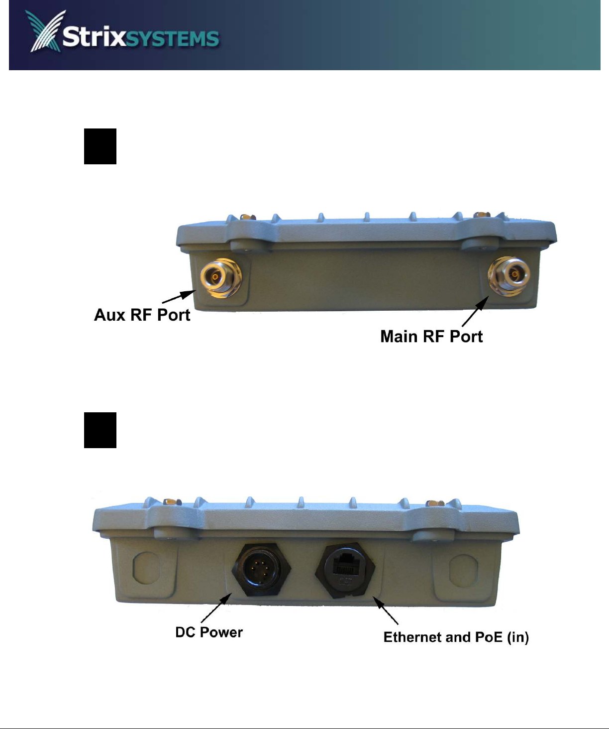
2
Front Panel Connectors
3
Rear Panel Connectors

MWS100 Installation Guide Page 3 of 4 Revision D4
8/29/2008
4
Installation
Note: The MWS100 must be installed by a trained professional installer only.
Failure to comply fully with these instructions may void the MWS100 warranty
and/or violate local safety or radio regulations.
1.
Select a mounting location for the MWS100. The MWS100 is designed for
indoor, outdoor and in-vehicle applications.
Note: In the U.S. the 5150-5250MHz band is only available for indoor applications. It is the
responsibility of the installer to configure the MWS100 to use of this band only when it is
installed indoor.
2. Select antennas with gain specifications according to the table below.
Note: The maximum allowable power for each antenna type is noted in the last column. The
installer must set the power correctly for the chosen antennas.
Frequency Antenna Type Connection Method Maximum
Gain
Maximum
Power Setting
2412-2462MHz
5150-5250MHz
5745-5850MHz
Linear Polarized
Dome LMR200 Cable (> 3 ft. length) 4 dBi Full
2412-2462MHz
5150-5250MHz
5745-5850MHz
Omni-directional Direct connection to MWS100
3 dBi
5 dBi
5 dBi
Full
2412-2462MHz Omni-directional LMR200 Cable (> 3 ft. length) 8 dBi Full
5745-5850MHz Omni-directional LMR200 Cable (> 3 ft. length) 12 dBi -3dB (23dBm)
4940-4990MHz Omni-directional LMR200 Cable (> 3 ft. length) 11 dBi Full
3. Mount the selected antennas securely following all antenna manufacturer
instructions and recommendations. Provide a suitable length of LMR-200 type
antenna cable between each antenna and the MWS100. If using only one
antenna, connect it to the port labeled “MAIN”. Connect a second antenna to
the port labeled “AUX”.
RF Exposure Requirements
To ensure compliance with FCC RF exposure requirements, the antenna used for
this wireless network device must be installed to provide a separation distance of a
minimum of 40cm or more from all persons, and must not be co-located or operated
in conjunction with any other antenna or radio transmitter. Installers and end-users
must follow these installation instructions.

MWS100 Installation Guide Page 4 of 4 Revision D4
8/29/2008
4. Using the supplied fused power cable, connect the BLACK wire to the system
ground and then attach the RED wire to the positive DC supply. The MWS100
is designed to operate from a minimum of 11 VDC* to a maximum of 52 VDC
and a maximum current draw of 2 A.
* A low-voltage cut-off circuit prevents the MWS100 from draining the vehicle
battery. The unit will automatically power down when the DC voltage falls
below 10.5 VDC. Operation will be restored once the DC voltage rises above
11.5 VDC.
The MWS100 may also be powered over its Ethernet port (LAN) by a PoE
power injector capable of sourcing 16 W.
5. Provide an Ethernet cable for connecting the MWS100 to a computer or router.
6. Attach the supplied fused power cable to the PWR connector on the EWS100
rear panel.
5
Configuration and Troubleshooting
If the MWS100 was provided by the Systems Integrator or WISP responsible for
operation of the Strix OWS network, then it will have been pre-configured for
correct operation on the wireless network (SSID, security, and other configuration
settings). Otherwise, contact the WISP for these settings and configuration
assistance.
If access to the troubleshooting feature has been made available, then a
convenient means to verify settings and network connection exists. On the Web
interface, click on the Monitor tab then click on Troubleshooting to display the
Troubleshooting window. Click on the Start Troubleshooting button to begin the
process.