Strix Systems OWS2430-90 802.11 a/b/g 4.9 GHz Wireless, Mesh Access Point User Manual accessone userguide
Strix Systems, Inc. 802.11 a/b/g 4.9 GHz Wireless, Mesh Access Point accessone userguide
Contents
User Manual Part 3 of 5
Access / One® Network
Managing the Network 73
5
After inputting data (or making selections), click on the Update button to update this
page, then click on the Apply Configuration tab to propagate your changes across
the network. If necessary, you can click on the factory default (FD) button in the
toolbar to reset all data on this page to its factory default state.
Network Management
General
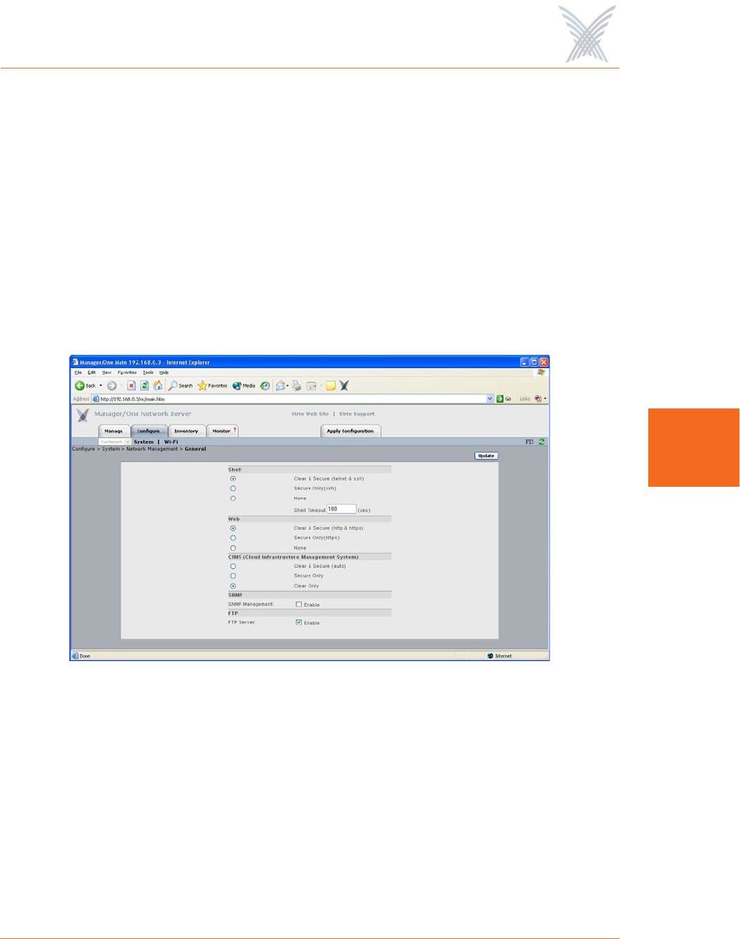
This command allows you to define the level of security for the various management
interface options used to manage your Access/One Network, and provides options
for enabling or disabling SNMP Management and FTP server functionality.
Figure 56. General Management Interface Security
The following options are available with this command:
◗Shell
Choose Clear & Secure to allow network management via an unsecured
Telnet connection and a Secure SHell (SSH) connection, or choose Secure
Only to restrict management to an SSH connection only. Alternatively, you
can choose None to prevent access from either option.

Access / One® Network
74 Managing the Network
5
If you are allowing access via Telnet or SSH, enter a value—in seconds—in
the Shell Timeout field to define how long the connection will remain open
during idle periods. Setting the shell timeout value to 0 (zero) will disable the
timer and keep the session open, even when idle.
◗Web
Choose Clear & Secure to allow network management from your Web
browser via HTTP (clear) and HTTPS (secure), or choose Secure Only to
restrict management via a secure HTTPS connection only. Alternatively, you
can choose None to prevent all Web management access.
◗CIMS (Cloud Infrastructure Management System)
Choose Clear & Secure to allow network management via CIMS, where
security levels are controlled automatically. Alternatively, you can define the
security level manually by choosing Secure Only or Clear Only.
◗SNMP Management
Check this box to enable network management via an SNMP (Simple
Network Management Protocol) management console. Your Access/One
Network supports the 802.11 MIB (Management Information Base), as well as
Strix proprietary MIBs. Any MIB I or MIB II compliant SNMP management
console (such as CiscoWorks or HP OpenView) can be used to manage your
network remotely.
◗FTP Server
Check this box to enable FTP server functionality (this box must be checked if
you want to update your firmware or transfer system configuration files).
After inputting data (or making selections), click on the Update button to update this
page, then click on the Apply Configuration tab to propagate your changes across
the network. If necessary, you can click on the factory default (FD) button in the
toolbar to reset all data on this page to its factory default state.
Access / One® Network
Managing the Network 75
5
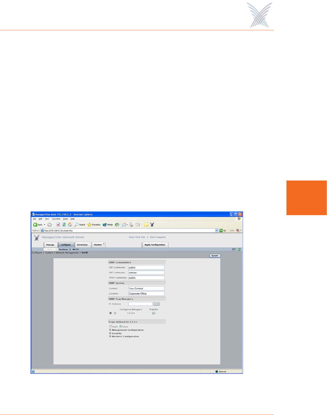
SNMP
This command allows you to define the SNMP Communities, the SNMP System, and
any specific SNMP Trap Managers. With SNMP enabled and the settings on this
page defined, your Access/One Network will support most common SNMP
management consoles.
The system also supports Syslog (System Logging) via an SNMP manager (in parallel
with basic Syslog services) where Syslog text information is encoded in an SNMP
trap message and presented to the operator.
SNMP (Simple Network Management Protocol is a standard protocol that regulates
network management over the Internet. SNMP uses TCP/IP to communicate with a
management platform, and offers a standard set of commands that make multi-
vendor operability possible. SNMP uses a standard set of definitions, known as a
MIB (Management Information Base), which can be supplemented with Enterprise-
specific extensions. Strix provides its own proprietary MIBs. For more information
about Strix MIBs, contact Strix technical support.
Figure 57. Configuring Access/One Network for SNMP
Access / One® Network
76 Managing the Network
5
The following options are available with this command:
◗SNMP Communities
Enter your GET Community (read), SET Community (write) and TRAP
Community in the corresponding fields. The defaults for these fields are:
•GET Community: public
•SET Community: netman
•TRAP Community: public
◗SNMP System
Enter the Contact and Location information for the person managing your
Access/One Network.
◗SNMP Trap Managers
Enter a valid IP address for any SNMP Trap Manager you intend to use. The
SNMP Trap Manager you choose must be enabled, so ensure that the
appropriate box is checked. If you have multiple SNMP Trap Managers
assigned, you can delete a manager by clicking on the X icon associated with
each manager.
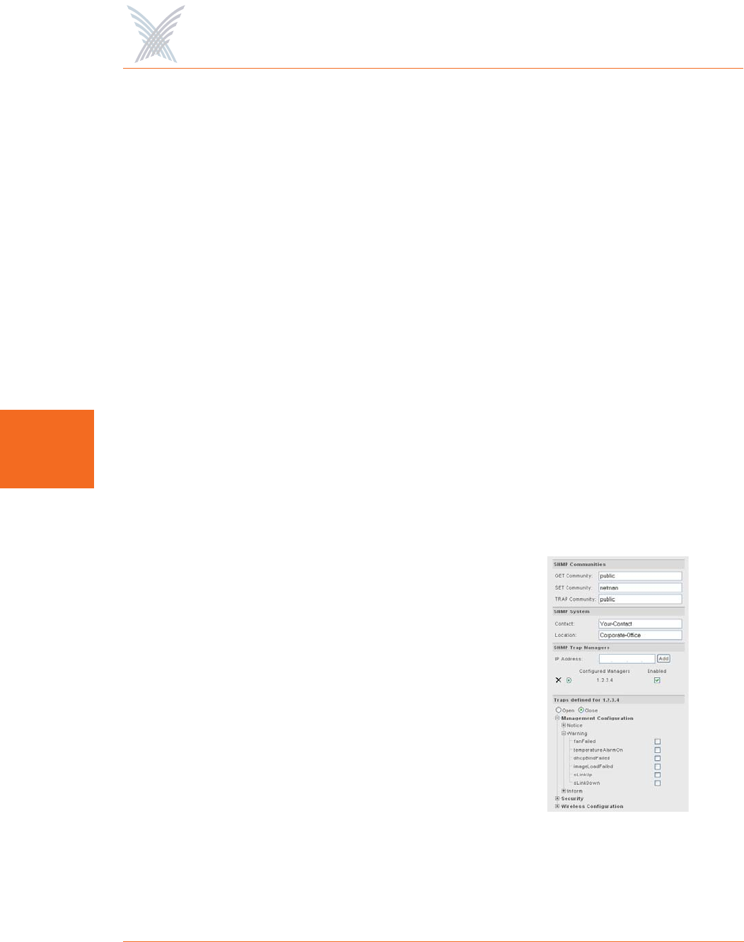
◗Traps
Choose Open to expand the primary
elements of the SNMP Trap Manager tree.
From here you can make management
selections by checking (or unchecking)
the appropriate check boxes. When
finished making your selections, choose
Close to collapse the tree.
After inputting data (or making selections), click
on the Update button to update this page, then
click on the Apply Configuration tab to
propagate your changes across the network. If
necessary, you can click on the factory default
(FD) button in the toolbar to reset all data on this
page to its factory default state.
Figure 58. Managing Traps
Access / One® Network
Managing the Network 77
5
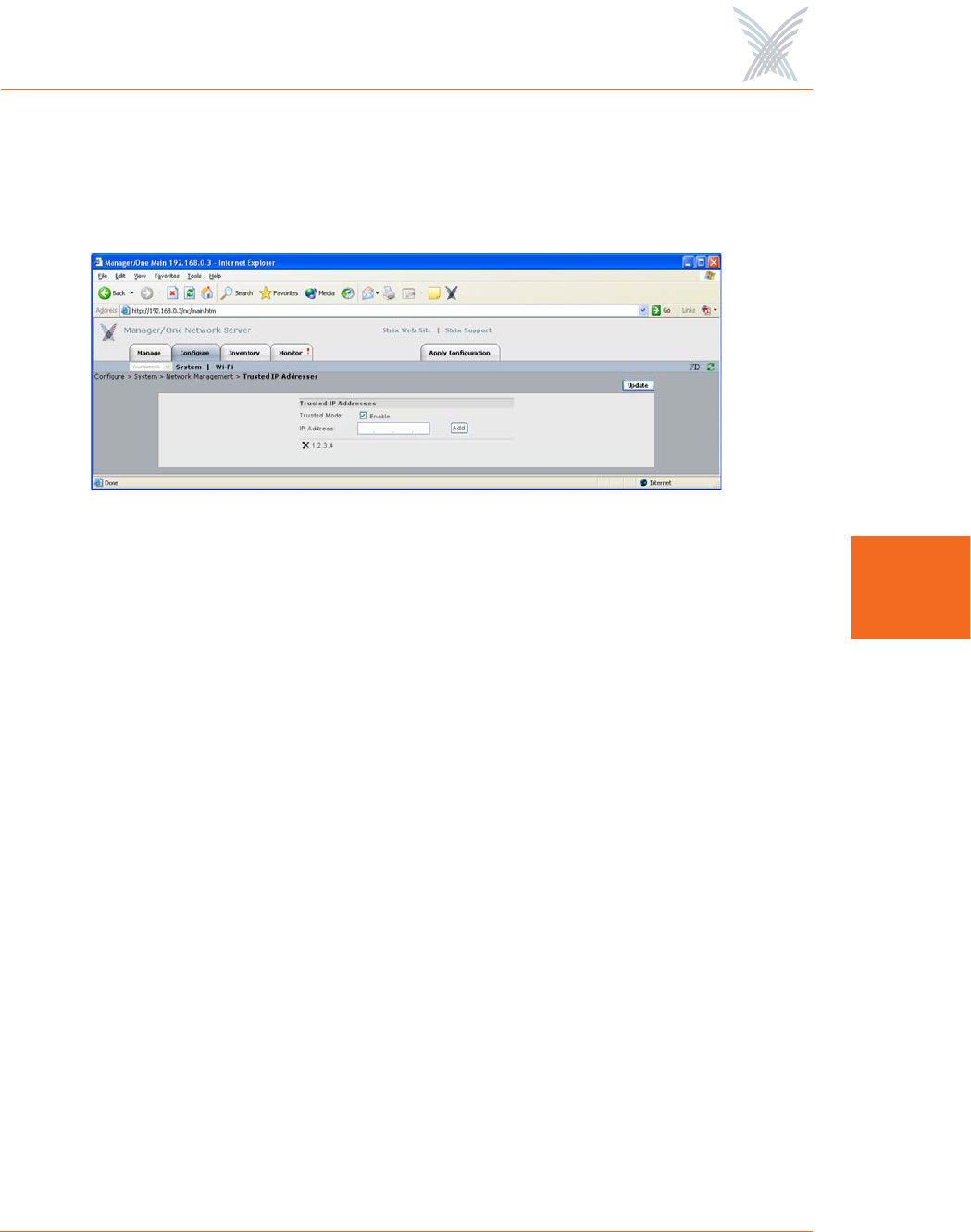
Trusted IP Addresses
This command allows you to enable or disable the Trusted Mode and assign specific
trusted IP addresses. When this mode is enabled, only addresses assigned here will
be trusted by the network for management at any network module.
Figure 59. Assigning Trusted IP Addresses
The following options are available with this command:
◗Trusted Mode
You can only enable this option if you have added at least one trusted IP
address. Once a trusted IP has been added, check this box to enable the
trusted mode (or uncheck the box if you want to disable this feature).
◗IP Address
You must add at least one IP address if you want to enable the trusted mode
feature. To add an address, simply enter a valid IP address in this field then
click on the Add button (the new address is listed below this field). You can
add as many trusted IP addresses as you want. To delete an address, click on
the X icon alongside the address, then confirm your request at the pop-up
dialog. However, if you have only one trusted IP address listed, you cannot
delete the address if the trusted mode is enabled—you must disable the
trusted mode before attempting to delete a sole trusted IP address.
After inputting data (or making selections), click on the Update button to update this
page, then click on the Apply Configuration tab to propagate your changes across
the network. If necessary, you can click on the factory default (FD) button in the
toolbar to reset all data on this page to its factory default state.
Access / One® Network
78 Managing the Network
5
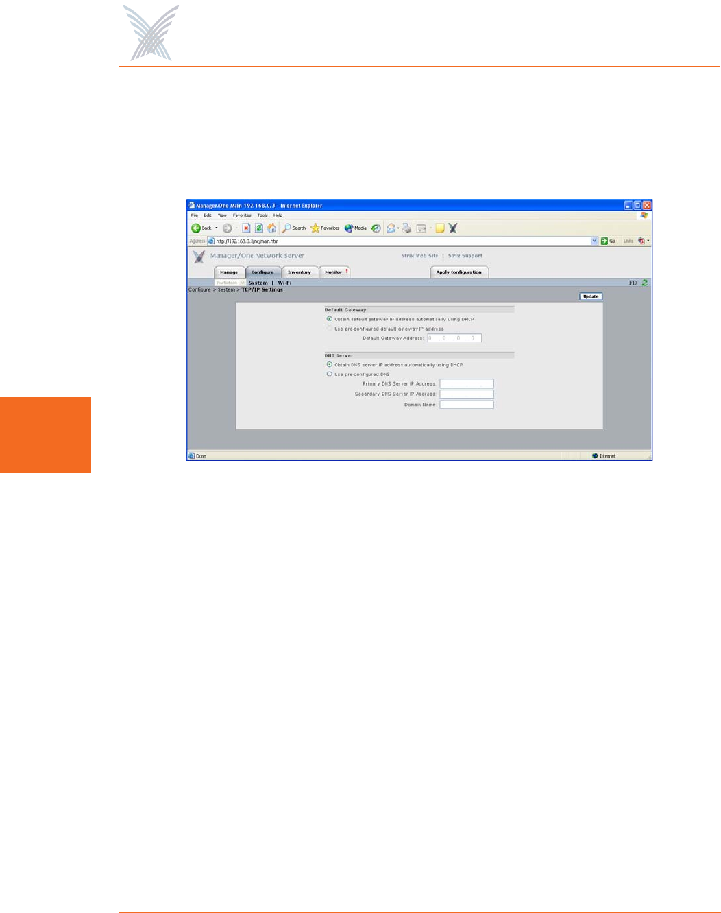
TCP/IP Settings
This command allows you to specify whether Access/One will obtain the Default
Gateway and DNS IP addresses automatically, or use pre-configured static IP
addresses.
Figure 60. TCP/IP Settings
The following options are available with this command:
◗Default Gateway
The system is set up to use DHCP (Dynamic Host Configuration Protocol) to
obtain the default gateway IP address automatically (default).
When using wireless uplinks between nodes, Access/One
Network’s self-tuning feature requires that a default gateway and/
or DNS is specified to determine delays to the host Ethernet.
When DHCP is used across the network (default), specifying
both of these will satisfy this requirement.
Access / One® Network
Managing the Network 79
5
◗DNS Server
Choose whether you want the system to use DHCP to obtain the DNS IP
address automatically (default), or use a pre-configured static IP address. If
you choose the latter option, enter IP addresses for the primary and
secondary (if any) DNS server. DNS is used by your Access/One Network
modules to lookup the names of various servers (for example, the RADIUS
and FTP servers). You must specify a Domain Name when static IP addresses
are used. This has the effect of appending the Domain Name to non-fully
qualified address requests (for example, the FTP server host name configured
as FTP123 will become FTP123.yourdomain.com).
After inputting data (or making selections), click on the Update button to update this
page, then click on the Apply Configuration tab to propagate your changes across
the network. If necessary, you can click on the factory default (FD) button in the
toolbar to reset all data on this page to its factory default state.
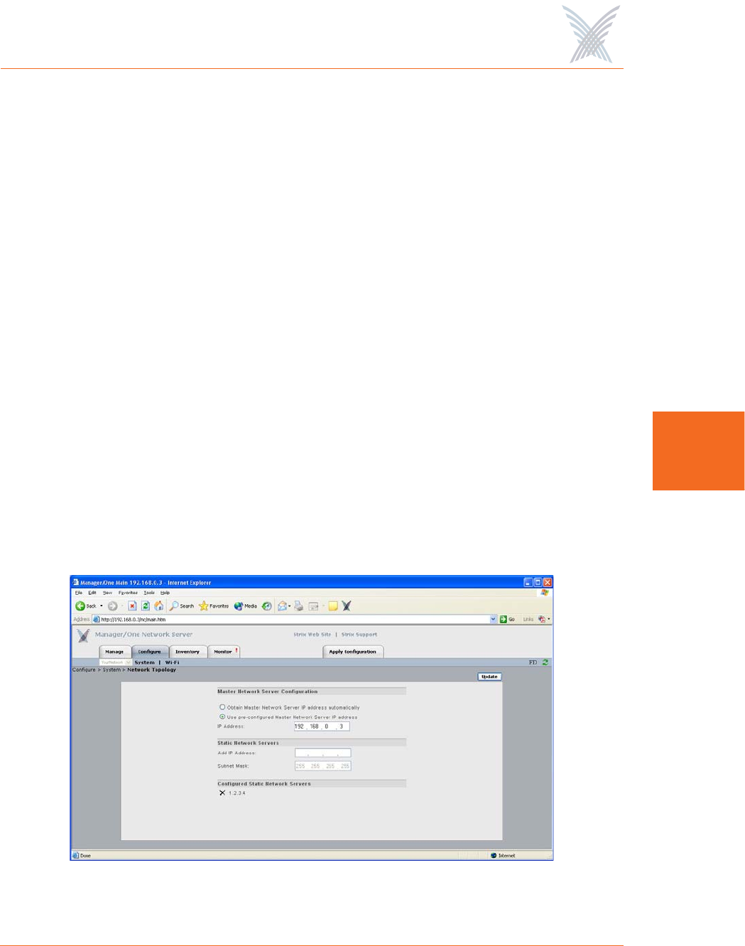
Network Topology
This command allows you to define whether your Access/One Network will obtain
its Master Network Server IP address automatically or use a pre-configured static IP
address. It also provides you with the option of defining any static network servers.
Figure 61. Network Topology

Access / One® Network
80 Managing the Network
5
The following options are available with this command:
◗Master Network Server Configuration
Establishing a master/slave relationship between network servers facilitates
efficient Wide Area Network management by reducing the amount of traffic
between two subnets on the same network, as well as providing a single
network server responsible for all Strix devices within its subnet. This feature
enables a Master Network Server to be statically or dynamically assigned for
every subnet (even within the same network), which Manager/One users are
redirected to if they try to log into a non-Master Network Server.
The Master Network Server supports SNTP (Simple Network Time Protocol)
and is responsible for sending out the correct clock for the subnet as part of
the CIMS protocol. In this way, only the Master Network Server need derive
the clock from an independent stratum 1 or 2 clock source. If the Master
Network Server fails, your Access/One Network quickly detects the failure, at
which point the network server with the next lowest IP address assumes the
role of master. In this case, when the failed Master Network Server comes
back online, it immediately re-establishes its role as master.
Choose whether you want the system to obtain the Master Network Server IP
address automatically (default), or use a pre-configured static IP address. If
you choose the latter option, enter a valid IP address in the appropriate field.
◗Static Network Servers
Static network servers are added to bond subnets together, allowing you to
configure and manage multiple subnets. You do this by starting with one
subnet and adding the Master Network Server IP addresses of other subnets to
tie them together.
Enter the IP address of a network server module on another subnet (the
default subnet mask is 255.255.255.255), then click on the Update button. to
add the server to a list. If you enter multiple static network servers, you must
click on the Update button after each entry for your changes to take effect.
To delete a static network server’s IP address, simply click on the X icon
alongside the address.
Access / One® Network
Managing the Network 81
5
After inputting data (or making selections), click on the Update button to update this
page, then click on the Apply Configuration tab to propagate your changes across
the network. If necessary, you can click on the factory default (FD) button in the
toolbar to reset all data on this page to its factory default state.
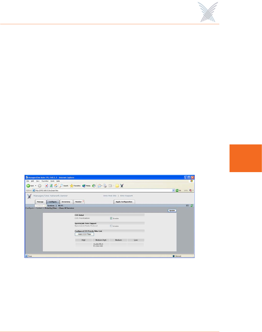
Priority/One - Class of Service
This command allows you enable and define Class of Service (CoS) filters to
prioritize traffic throughout your Access/One Network. Supported filters include:
◗VLAN
◗IP TOS (Type of Service)
◗IP Protocol
CoS filters establish separate queues for different priority streams based on the filters
you define here. Data streams are then serviced according to their priority. In
addition, this command allows you to enable or disable the SpectraLink® Voice
Support feature.
Figure 62. Priority/One
The following options are available with this command:
◗COS Global
Check the COS Prioritization box to enable COS filtering across the network,
or uncheck the box to disable the COS filtering functionality.
Access / One® Network
82 Managing the Network
5
◗Spectralink Voice Support
Check the SpectraLink Radio Protocol box to enable the SpectraLink Voice
Support feature across the network. This feature gives a controlled preference
to voice packets over data packets, ensuring that all voice packets are
transmitted efficiently. Access/One Network prioritizes SpectraLink voice
traffic over user data traffic.
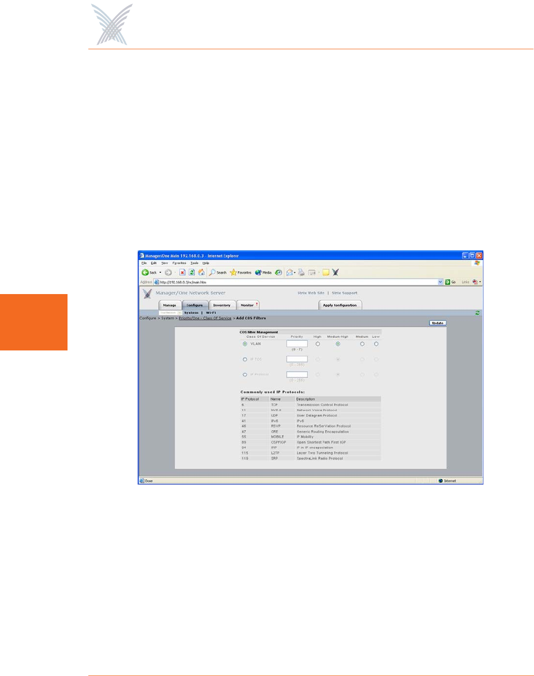
◗Configured COS Priority Filter List
If you want to add a specific COS filter, click on the Add COS Filter button to
display the COS Filter Management window. From here, you can add Class of
Service filters and establish priorities for each class.
Figure 63. Adding COS Filters
For each COS filter you add, you must click on the Update button to apply
the change—you can only add one filter at a time. Each time you add a COS
filter, Manager/One returns you to the main Priority/One page where you will
see the new filter appended to a list. The list appears immediately under the
Add COS Filter button.

Access / One® Network
Managing the Network 83
5
To edit or delete an assigned filter that appears in the list, click on the filter to
generate the COS Filter Priority Settings window. From here you can edit or
delete filters. To delete a filter, click on the X icon next to the filter in this
window.
Figure 64. Editing or Deleting COS Filters
After inputting data (or making selections), click on the Update button to update this
page, then click on the Apply Configuration tab to propagate your changes across
the network. If necessary, you can click on the factory default (FD) button in the
toolbar to reset all data on this page to its factory default state.
Click here to delete
Access / One® Network
84 Managing the Network
5
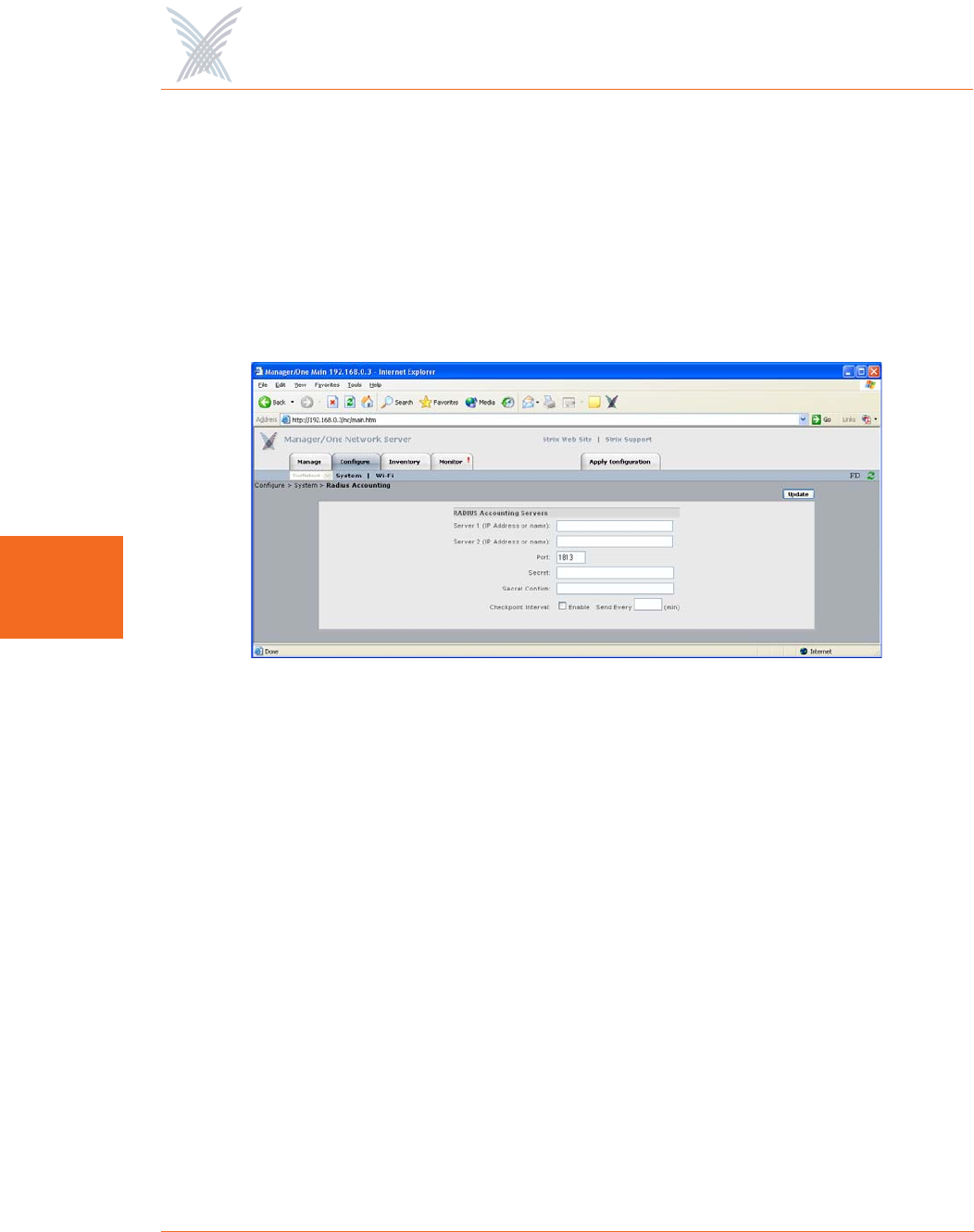
Radius Accounting
Through a wireless interface, your Access/One Network supports RFC 2866
standard RADIUS (Remote Authentication Dial-In User Service) accounting,
allowing customers with existing RAS Radius-parsing scripts/tools to leverage their
investment as well as customize their tools to extract all available statistical
information. This command allows you to configure up to two RADIUS accounting
servers, set up an authorization port, and establish a secret key.
Figure 65. Setting Up RADIUS Accounting Servers
The following options are available with this command:
◗Server 1 (IP Address or Name)
Enter a valid IP address or name for Server 1.
◗Server 2 (IP Address or Name)
If you require a second (backup) server, enter a valid IP address or name for
Server 2. Server 2 is only used if Server 1 becomes unavailable.
◗Port
Enter the authorization port for the primary RADIUS server (Server 1) in this
field. This is the port the system uses when authorizing users.

Access / One® Network
Managing the Network 85
5
◗Secret
Enter a secret key in this field for the primary RADIUS server. During the
authentication process, the server and client exchange secret keys. The secret
keys must match for communication between the server and the client to
continue. The secret key is a valuable and necessary security measure.
◗Secret Confirm
Confirm your secret key in this field.
◗Checkpoint Interval
Check this box to enable a checkpoint interval, or uncheck this box to disable
this feature.
◗Send Every
Once an interval time (in minutes) is established in this field, the reporting
module will send interim reports for each wireless device associated to it at
this interval period.
After inputting data (or making selections), click on the Update button to update this
page, then click on the Apply Configuration tab to propagate your changes across
the network. If necessary, you can click on the factory default (FD) button in the
toolbar to reset all data on this page to its factory default state.
Syslog
Access/One Network offers comprehensive Syslog (system logging) functionality,
including the ability to monitor Syslog events. Logged events can be sent to multiple
Syslog servers, though using more than one server can impact the system’s
performance. This command allows you to:
◗Define your Syslog configuration parameters.
◗Assign the Syslog (system logging) server IP address.
◗Define the event logging destination (Command Line Interface, SNMP Syslog
MIB, or a defined Syslog server IP address).
◗Establish the reporting level for each Access/One Network function (security,
wireless, management, and other).
Access / One® Network
86 Managing the Network
5
To access the Syslog window, choose Syslog from the System pull-down menu in the
Configure function.
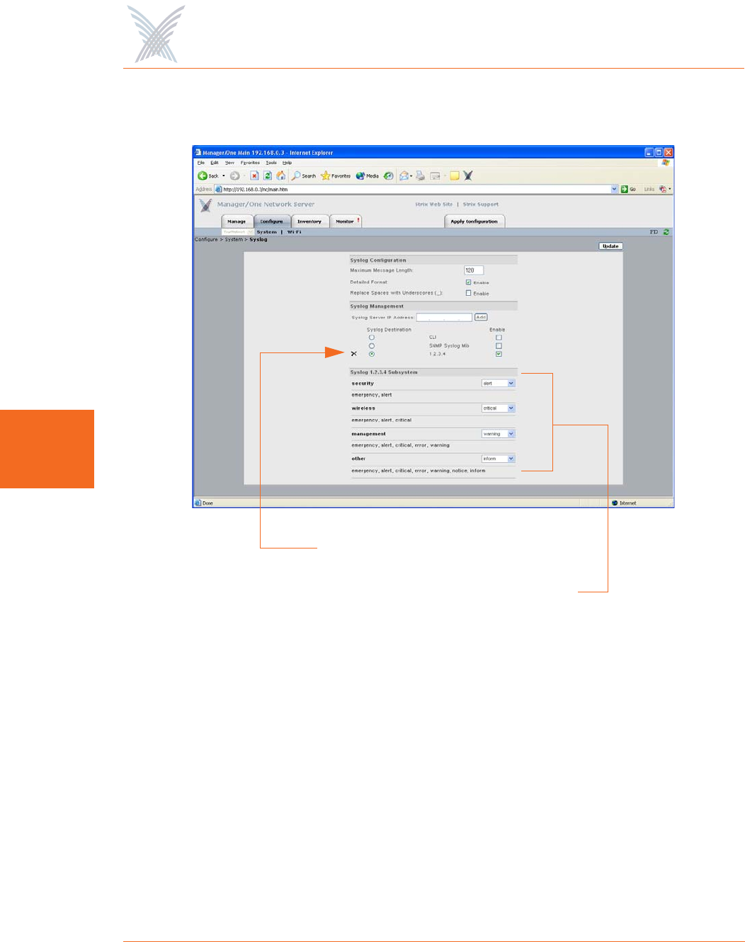
Figure 66. Configuring Access/One Network for Syslog
The following options are available with this command:
◗Syslog Configuration
This category allows you to define the Maximum Message Length, where the
character length of Syslog messages will be restricted to the number you
define here. In addition, you can enable/disable the Detailed Format feature
which determines the level of detail reported in each message, and also
enable a feature that forces the system to Replace Spaces with Underscores in
messages.
Server IP Address added here
Reporting Levels

Access / One® Network
Managing the Network 87
5
◗Syslog Management
Enter a valid IP address for the Syslog server, then click on the Add button to
add this server to the list of available Syslog destinations. You can add
additional servers, but assigning multiple servers may degrade the system’s
performance. Once you’ve assigned the server(s), choose the destination for
your event logging (CLI, SNMP Syslog MIB, and/or the Syslog server you
assigned). The destination(s) you choose must be enabled, so ensure that the
appropriate box is checked. If you have multiple IP addresses assigned, you
can delete an IP address by clicking on the X icon next to the IP address.
◗Syslog CLI Subsystem
Select the reporting level for each function (security, wireless, management,
and other) from the corresponding pull-down list. Your available choices are:
•none
•emergency
•alert
•critical
•error
•warning
•notice
•inform
•all
If you select all from the pull-down list, this will include the debug level. The
debug level will significantly increase (almost double) the number of Syslog
messages that are returned and significantly degrade performance. The debug
level should not be used for routine Syslog monitoring. For more information
about Syslog messages, see “Syslog Messages” on page 177.
After inputting data (or making selections), click on the Update button to update this
page, then click on the Apply Configuration tab to propagate your changes across
the network. If necessary, you can click on the factory default (FD) button in the
toolbar to reset all data on this page to its factory default state.
Access / One® Network
88 Managing the Network
5
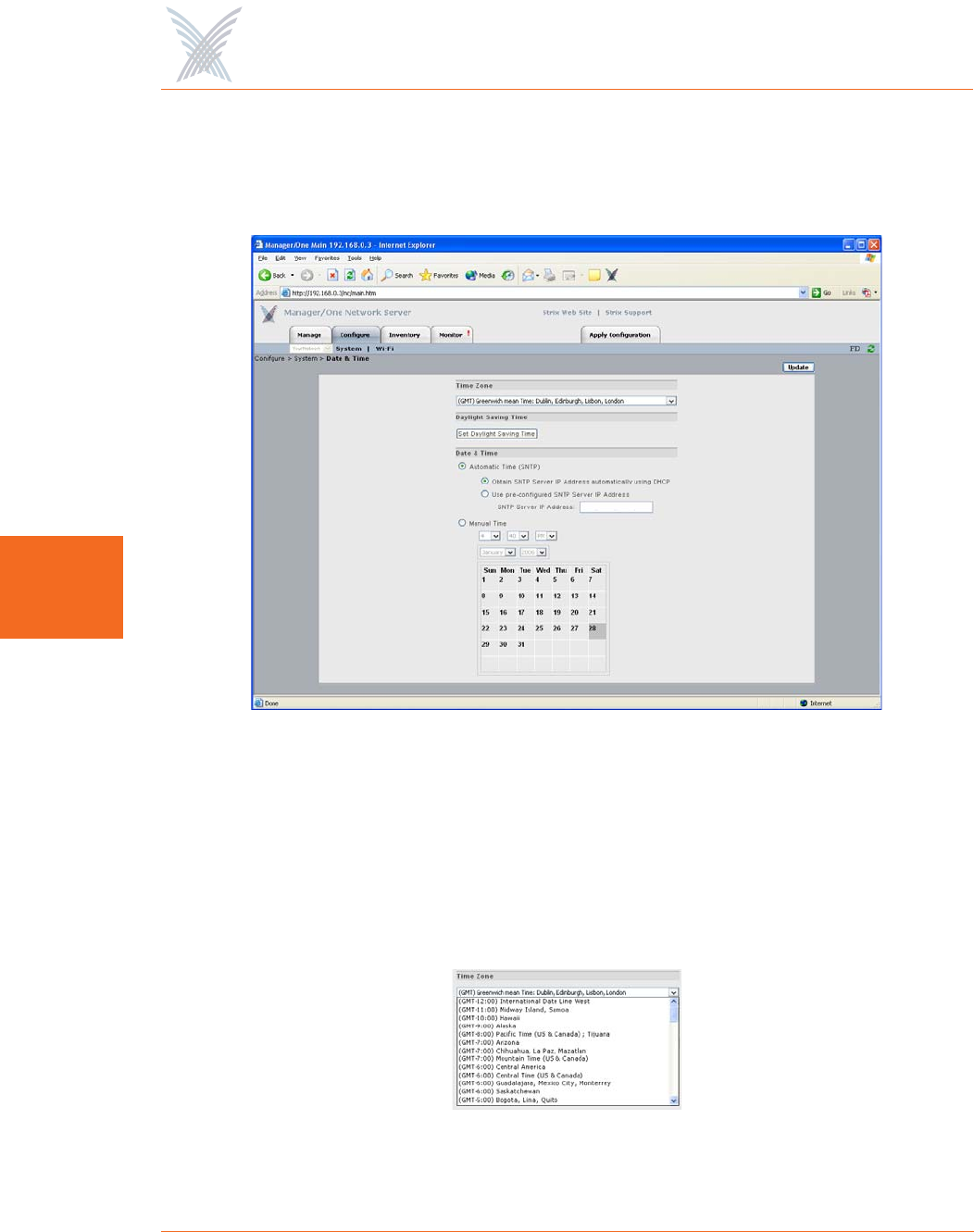
Date and Time
This command allows you to set the time zone, define daylight saving parameters,
and choose between automatic time and manual time.
Figure 67. Establishing the Correct Date and Time for Your Environment
The following options are available with this command:
◗Time Zone
Select the time zone from the pull-down list that applies to the geographic
location where your Access/One Network is operating. The default time zone
is Greenwich Mean Time (GMT).
Figure 68. Time Zones
Access / One® Network
Managing the Network 89
5
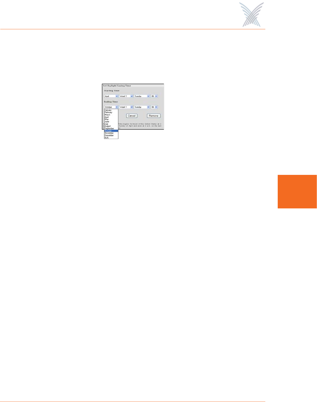
◗Daylight Saving Time
This option allows you to configure the Daylight Saving Time for your chosen
time zone. Click on the Set Daylight Saving Time button to reveal the
configuration window.
Figure 69. Configuring Daylight Saving Time
Choose the month, week, day and year from the available pull-down menus
for both the Starting Time and Ending Time to establish your daylight saving
time. To apply your selections, click on the Update button in the Set Daylight
Saving Time window (not the Update button on the main page). To remove all
daylight saving time settings, simply click on the Remove button. You can
also close this window without making changes (or even after making
changes) by clicking on the Cancel button.
◗Date and Time
This option allows you to choose between Automatic Time and Manual time
settings:
•Automatic Time (SNTP)
SNTP (Simple Network Time Protocol) is an adaptation of the Network
Time Protocol (NTP), used to synchronize computer clocks within the
Internet. SNTP can operate in both unicast modes (point-to-point) and
broadcast modes (point-to-multipoint). It can also operate in IP multicast
mode where this service is available. If you selected Automatic Time
(SNTP), you must choose whether you want the system to use DHCP to
obtain the SNTP Server IP address automatically, or use a pre-configured
static IP address. If you select the latter option, you must enter a valid IP
address in the SNTP Server IP Address field.

Access / One® Network
90 Managing the Network
5
With the Automatic Time (SNTP) option selected, the master network
server transmits time/date synchronization packets periodically to Strix
devices using the Strix Time Distribution (STD) protocol. Stack controllers
use STD to adjust their own time and date. Time and date information is
distributed in Greenwich Mean Time (GMT), allowing each device to
adjust for its own time zone. This allows Access/One Network to span
large geographic areas while maintaining time coherence.
If SNTP is configured at the network level, the master network server will
proxy the SNTP time requests on behalf of your entire Access/One
Network. The master network server effectively queries the SNTP server
periodically and adjusts its own time/date accordingly. STD time/date
information is then sent to all Strix devices on the network. If the master
network server fails (for any reason), all Strix devices will then query the
SNTP server individually.
•Manual Time
Choose this option if you want to set the date and time manually. To do
this, simply make your selections from the pull-down menus provided for
hour, minute, AM/PM, month and year, then click on the day of the
month on the calendar provided.
Figure 70. Setting Manual Time
After inputting data (or making selections), click on the Update button to update this
page, then click on the Apply Configuration tab to propagate your changes across
the network. If necessary, you can click on the factory default (FD) button in the
toolbar to reset all data on this page to its factory default state.
Access / One® Network
Managing the Network 91
5
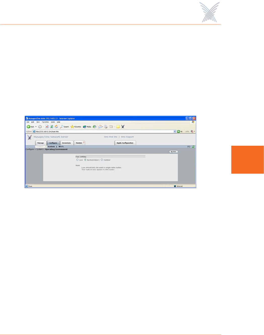
Operating Environment
This command is applicable to the IWS only. It displays the Fan Setting window and
allows you to choose between a Low, Normal (Indoor) and Outdoor speed setting
for the node’s cooling fan. Choose Normal if the affected node is to be installed in
an environment with a regulated temperature, otherwise choose High if the
operating environment is uncontrolled and prone to fluctuating temperatures and/or
humidity. Generally, the Normal setting is used for indoor applications while the
High setting is used for outdoor applications. Only use the Low setting for nodes
with single radio configurations.
Figure 71. Setting the Cooling Fan Speed
After inputting data (or making selections), click on the Update button to update this
page, then click on the Apply Configuration tab to propagate your changes across
the network. If necessary, you can click on the factory default (FD) button in the
toolbar to reset all data on this page to its factory default state.
Firmware Updates
This command allows you to set FTP parameters at the network level so that your
Access/One Network knows where to find the new firmware (BIN) files. Procedural
information for updating your Access/One Network’s firmware has already been
covered in “Updating Firmware Across the Network” on page 37.
If you are uncertain about your FTP server’s configuration parameters, consult with
your network administrator.
Access / One® Network
92 Managing the Network
5
Wi-Fi
This area of Manager/One contains the primary configuration commands for your
Access/One Network in the Wi-Fi environment. Any commands executed here are
applied to all wireless modules, so make sure the changes you initiate are changes
that you want to apply to the entire network, otherwise go to “Managing Subnets
and Nodes” on page 127 or “Managing Modules” on page 133.
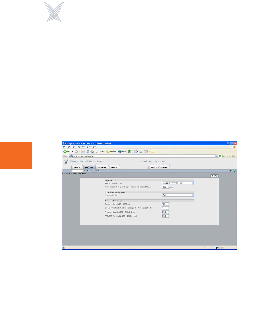
General
This command allows you to define your Access/One Network’s general radio
parameters for 4.9 GHz Public safety, 802.11a and 802.11g radios. These radio
parameters are applied across the entire network. If you want to set up the radio
parameters for a specific wireless module, go to “Radio Parameters” on page 147.
Figure 72. Setting Up General Radio Parameters

Access / One® Network
Managing the Network 93
5
◗Allow Association Over Long Distances (25 miles/40 km)
This option allows you to set a distance (up to 25 miles or 40 kilometers) for
wireless associations over long distances (the default is 3 miles). Be aware
that changing the distance here will affect all wireless modules. We
recommend setting this value at the module level. For example, if you have a
single 10 mile link and many shorter links setting this value to 10 miles will
affect all links and slow down the network.
◗Frequency/Rate/Power
•Transmit Power
This option allows you to select the level of transmit power from the
choices available in the pull-down list (either Full, Half, Quarter, One
Eighth, or Minimum). You can decrease the transmit power to decrease
the range of the wireless modules in your Access/One Network. The
default value for this parameter is Full (maximum power).
Depending on the selected antenna(s) for your application—especially
relevant to the OWS—it may be necessary to configure the transmit
power. It is the installer's responsibility to ensure that the transmit power
is set correctly for the chosen antenna(s). Operation in a manner other
than is represented in this document is a violation of FCC rules.
For a complete listing of the maximum power settings allowed for
antennas, go to “Power Settings for Antennas” on page 167.
◗Advanced Settings
These advanced settings are preconfigured with the optimum settings for your
Access/One Network. Changing any of these settings may negatively affect
the network’s performance. For best results, leave these settings at their
default values.
•Beacon Interval
The beacon is a uniframe system packet broadcast by the AP to keep the
network synchronized. Enter a value in this field between 20 and 1000
(milliseconds) that specifies the beacon interval. The default value is 100.

Access / One® Network
94 Managing the Network
5
•Delivery Traffic Indication Message (DTIM Period)
Enter a value between 1 and 255 that specifies the Delivery Traffic
Indication Message (DTIM). Increasing this interval allows the station to
sleep for longer periods of time resulting in power savings (in exchange
for some degradation in performance). The default value is 1.
•Fragment Length
Enter a value between 256 and 2346. This setting determines the size of
the wireless frame. Wireless frames are reassembled by your Access/One
Network wireless modules before being forwarded to the Ethernet port,
but only if the frame is smaller than the Ethernet MTU (1536 bytes). The
default value is 2346.
•RTS/CTS Threshold
This is a value that determines at what frame length the RTS-CTS function
is triggered. By default, the threshold is set at its highest value. A lower
value means that the RTS-CTS function is triggered for smaller frame
lengths. A lower threshold value may be necessary in environments with
excessive signal noise or hidden nodes, but may result in some
performance degradation. Enter a value between 256 and 2346 to specify
the RTS/CTS threshold. The default value is 2346.
Access / One® Network
Managing the Network 95
5
Radio Parameters
This command allows you to define your Access/One Network’s radio parameters
for all 4.9 GHz Public Safety, 802.11a and 802.11g radios. If you want to set up the
radio parameters for a specific wireless module, go to “Radio Parameters” on
page 147.
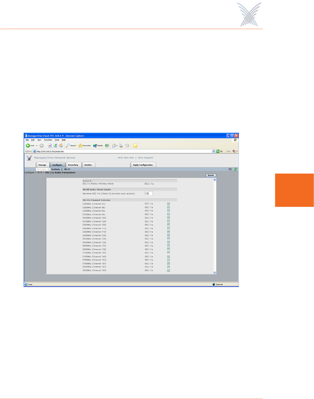
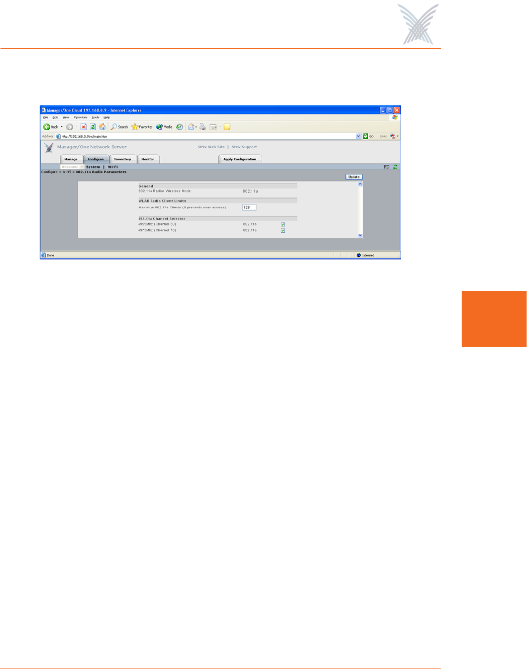
Figure 73 shows an example of the Radio Parameters configuration page for 802.11a
radios operating in the 5.250 GHz to 5.350 GHz, 5.470 GHz to 5.725 GHz, and
5.745 GHz to 5.825 GHz wireless bands.
Figure 73. 802.11a Radio Parameters
Access / One® Network
96 Managing the Network
5
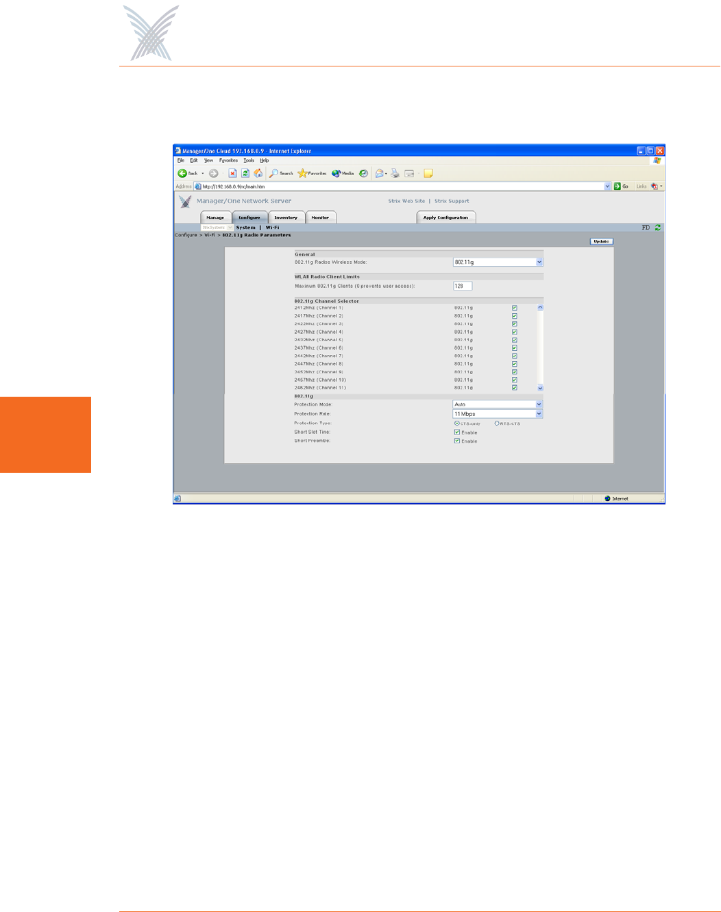
Figure 74 shows an example of the Radio Parameters configuration page for 802.11g
radios operating in the 2.400 GHz to 2.4835 GHz wireless band.
Figure 74. 802.11g Radio Parameters (2.400 GHz to 2.4835 GHz)
Access / One® Network
Managing the Network 97
5
Figure 75 shows an example of the Radio Parameters configuration page for radios
operating in the 4.940 GHz to 4.990 GHz wireless band.
Figure 75. Public Safety Radio Parameters (4.940 GHz to 4.990 GHz)
802.11a Radio Parameters at the Network Level
The following options are available with the Radio Parameters command for all
802.11a radios at the network level:
◗802.11a Radios Wireless Mode
This option is not configurable at the network level. If you want to set up the
wireless mode for a specific 802.11a wireless module, go to “Radio
Parameters” on page 147.
◗Maximum 802.11a Clients
This option allows you to restrict the number of 802.11a clients that can
associate with each 802.11a access point. The default is 128. Setting this field
to 0 (zero) prevents all 802.11a client access.
◗802.11a Channel Selector
These options extend the range of 802.11a wireless capability by allowing
you to select 802.11a wireless channels. Check the corresponding box to
enable an 802.11a channel of your choice.

Access / One® Network
98 Managing the Network
5
802.11g Radio Parameters at the Network Level
The following options are available with the Radio Parameters command for all
802.11g radios at the network level:
◗802.11g Radios Wireless Mode
This option allows you to select the 802.11g wireless mode from the options
available in the corresponding pull-down list, including:
•802.11g: This is the default standard 802.11g wireless mode.
•802.11g Only (No 802.11b): This mode restricts the radio to the 802.11g
wireless mode only and does not allow 802.11b compatibility.
•802.11b Only (No 802.11g): This mode restricts the radio to the 802.11b
wireless mode only and does not allow 802.11g compatibility.
◗Maximum 802.11g Clients
This option allows you to restrict the number of 802.11g clients that can
associate with each 802.11g access point. The default is 128. Setting this field
to 0 (zero) prevents all 802.11g client access.
◗802.11g Channel Selector
These options extend the range of 802.11g wireless capability by allowing
you to select 802.11g wireless channels. Check the corresponding box to
enable an 802.11g channel of your choice.
◗802.11g (only)
These options allow you to set up how your 802.11g wireless modules
perform on the network (not applicable to 802.11a radios). Options that are
specific to 802.11g radios include:

Access / One® Network
Managing the Network 99
5
•Protection Mode
This is a mechanism to let 802.11g devices know when they should use
modulation techniques to communicate with another 802.11b device,
especially in wireless networks where there is a mixed environment that
has 802.11g and 802.11b clients (and the clients are hidden from each
other. The protection mode options include the following:
–None
This assumes there are no wireless stations using 802.11b (11 Mbps)
technology. If operating in a mixed 802.11b/g network with minimal
802.11b traffic, choose this option to ensure the best performance for
your 802.11g stations.
–Always
Protects 802.11b traffic from colliding with 802.11g traffic. This
mode is not recommended, especially if only a few wireless stations
are operating with 802.11b. Only use this mode in environments
with heavy 802.11b traffic or where there is interference.
–Auto
This is the default mode and will enable protection for 802.11g
stations if your Access/One Network finds an 802.11b client. In this
mode, if the 802.11b client leaves the network the protection mode
will revert to None automatically.
•Protection Rate
Sets the data rate at which the RTS-CTS (Request-to-Send and Clear-to-
Send) packets are sent (either 1 Mbps, 2 Mbps, 5.5 Mbps, or 11 Mbps).
The 11 Mbps data rate is the default.

Access / One® Network
100 Managing the Network
5
•Protection Type
This option is only relevant when the Protection Mode is on. The options
here are CTS-only or RTS-CTS. With CTS-only, the client is not required
to send an RTS (Request-to-Send) to the AP. As long as the client receives
a CTS (Clear-to-Send) frame from the AP then the client is free to send
data. With the RTS-CTS option enabled, the client is required to send an
RTS to the AP and wait for a CTS from the AP before it can send data (this
option creates additional overhead and can cause performance
degradation). The default is CTS-only.
•Short Slot Time
802.11g defines the long slot time as 20 microseconds and a short slot
time as 9 microseconds. 802.11b only supports the long slot time of 20
microseconds. In an environment with 802.11g devices only, this option
(Short Slot Time) must be enabled for better performance—giving
precedence to 802.11g traffic. Only disable this option in mixed
(802.11b and 802.11g) environments. The default is enabled.
•Short Preamble
Short slot preamble improves network efficiency by reducing the
preamble from 128 bits to 56 bits. 802.11g is required to support both
short and long preambles (802.11b support for a short preamble is
optional). If this option is enabled, any 802.11b clients associated with
the network must support a short preamble. The default for this option is
enabled.
After inputting data (or making selections), click on the Update button to update this
page, then click on the Apply Configuration tab to propagate your changes across
the network. If necessary, you can click on the factory default (FD) button in the
toolbar to reset all data on this page to its factory default state.
Access / One® Network
Managing the Network 101
5
Client Connect
Client Connect (Virtual/Strix) is the system topology that enables your Access/One
Network to support and provide access to client devices using most wireless
technologies, including 802.11a or 802.11g. With Client Connect you can
customize each network node to support the wireless technologies you need in the
locations you need them. Any mix of these technologies can be supported within a
single node or across the entire Access/One Network.
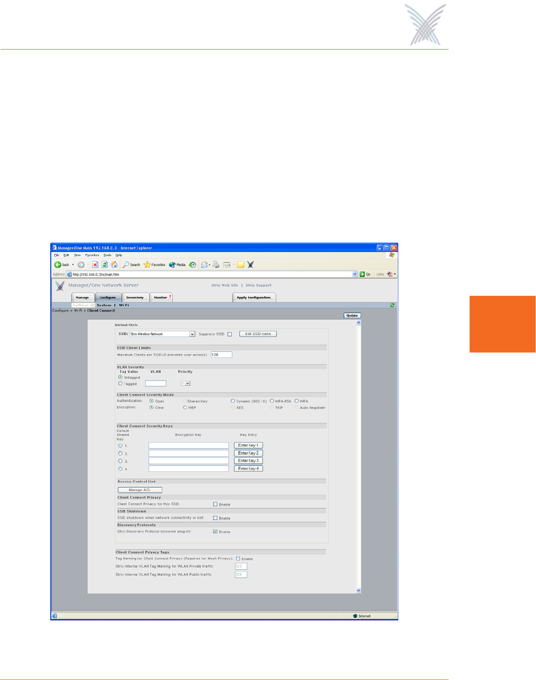
This command allows you to define your Client Connect parameters. The following
graphic shows the Client Connect window set to its default values.
Figure 76. Client Connect (Virtual/Strix)
Access / One® Network
102 Managing the Network
5
The following options are available with this command:
◗SSID
An SSID (Service Set Identifier) is a unique name shared among all devices in
a wireless network. Choose the network (SSID) or choose Add /Remove SSIDs
from the pull-down list. If you add an SSID, the new SSID can be up to 32
alphanumeric characters and the characters are case-sensitive. In addition to
adding and/or deleting SSIDs, this option allows you to edit an existing SSID
name.
•Choosing an Existing SSID
To choose an existing SSID, simply select it from the pull-down list.
•Editing the Name of an Existing SSID
To edit the name of an existing SSID, choose an SSID from the pull-down
list then click on the Edit SSID Name button. The SSID name is now
editable and you can change it by over-typing on the existing name. If
you do this, you must click on the Update button to apply your change.
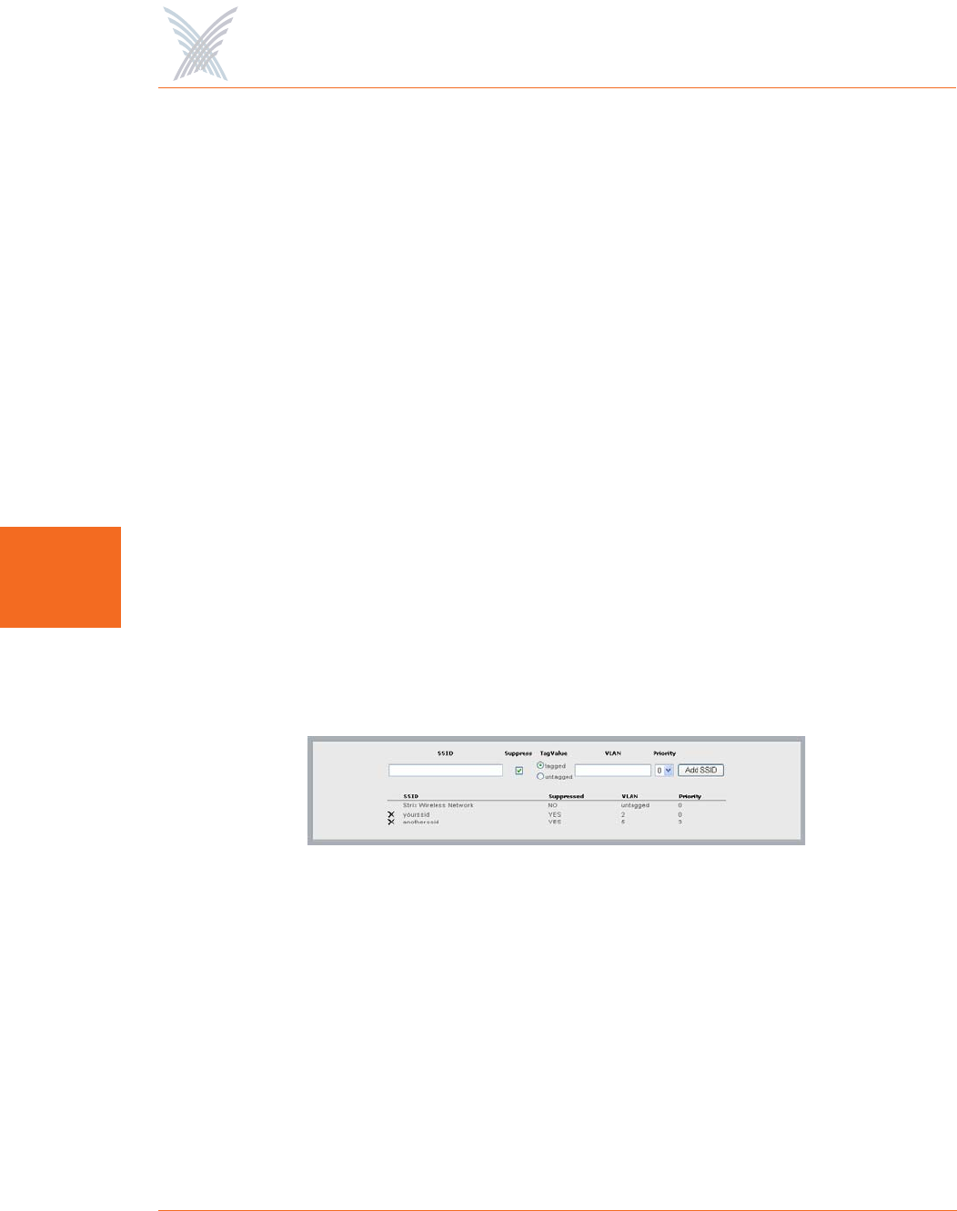
•Creating a New SSID
To create a new SSID, choose Add/Remove SSIDs from the pull-down list
to reveal the Add/Remove SSID window.
Figure 77. Adding an SSID
Enter a name for the new SSID in the SSID field. Check the Suppress SSID
box if you want to prevent the broadcast of this SSID in beacons from all
wireless modules in your Access/One Network (recommended).
Access / One® Network
Managing the Network 103
5
Choose whether the new SSID should be tagged or untagged. However,
there can be only one untagged SSID in the SSID table (the default SSID
is always untagged). From this window you also have the option of
assigning VLAN Security to the new SSID. When you have completed all
data input for the creation of your new SSID, click on the Add SSID
button. The new SSID is added to the list and will appear in the pull-
down list in the main Client Connect window.
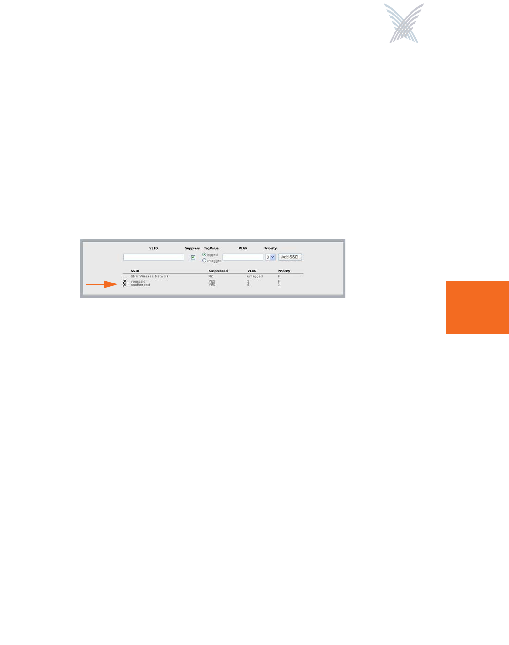
•Deleting an SSID
To delete an existing SSID, simply click on the X icon next to the SSID
you want to delete.
Figure 78. Deleting an SSID
◗SSID Client Limits
Enter a value (up to 128) in the Maximum Clients per SSID field. The default
is 128. If you enter a value of 0 (zero) you will effectively prevent all user
access, with the exception of any Strix Network Connect devices.
◗VLAN Security
You can now associate a tagged or untagged VLAN with the selected SSID. If
you define a tagged VLAN, you must assign a priority to it. The acceptable
range for priorities is between 0 and 7, and the priority is chosen from the
pull-down list. The lower the priority level you assign, the higher the priority
will be given by a VLAN-aware Ethernet switch. Access/One Network does
not support these priority levels as a queuing mechanism and ignores them
while the frame is in transit through the network. The VLAN mechanism
applies strictly to wireless stations. All devices on your Access/One Network
generate only untagged traffic.
Click here to delete this SSID

Access / One® Network
104 Managing the Network
5
◗Client Connect Security Mode
This option allows you to establish the authentication and encryption security
modes for Client Connects. These include:
•Authentication
–Open: Used for local authentication.
–Shared Key: This option is not currently supported.
–Dynamic Key (802.1X): With this option, the RADIUS server gives a
key to each user for unicast traffic. Multicast traffic uses the default
key.
–WPA-PSK: With this option, the WPA (Wi-Fi Protected Access)
standard uses a Pre-Shared Key (PSK) mode that does not require the
RADIUS infrastructure.
–WPA: This option provides WPA, a subset of the 802.11i standard
that boosts the original static WEP security by mandating 802.1x
remote authentication.
•Encryption
–Clear: Available for Open or Dynamic authentication. Messages will
be sent unencrypted between user devices and your Access/One
Network nodes.
–WEP: Wired Equivalency Privacy (WEP) is a security protocol for
WLAN. It encrypts data using an RC4 stream cipher of 64, 128 or
152 bits.
–AES: Advanced Encryption Standard (AES) encrypts data using a
symmetric 152 bit data block, and is generally considered the most
secure option available.
–TKIP: The Temporal Key Integrity Protocol (TKIP) is part of the IEEE
802.11i encryption standard for wireless LANs, providing per-packet
key mixing, a message integrity check and a re-keying mechanism.
–Auto Negotiate: With this option, the encryption mode will be
negotiated in real time between the participating devices, allowing
the simultaneous use of AES and TKIP.
Access / One® Network
Managing the Network 105
5
Select the desired Authentication and Encryption modes from the available
options. If you choose Dynamic (802.1x) or WPA authentication, you must
configure the RADIUS server(s) on this page (these fields only appear when
Dynamic or WPA is selected as the authentication type). See also, “Radius
Accounting” on page 84.
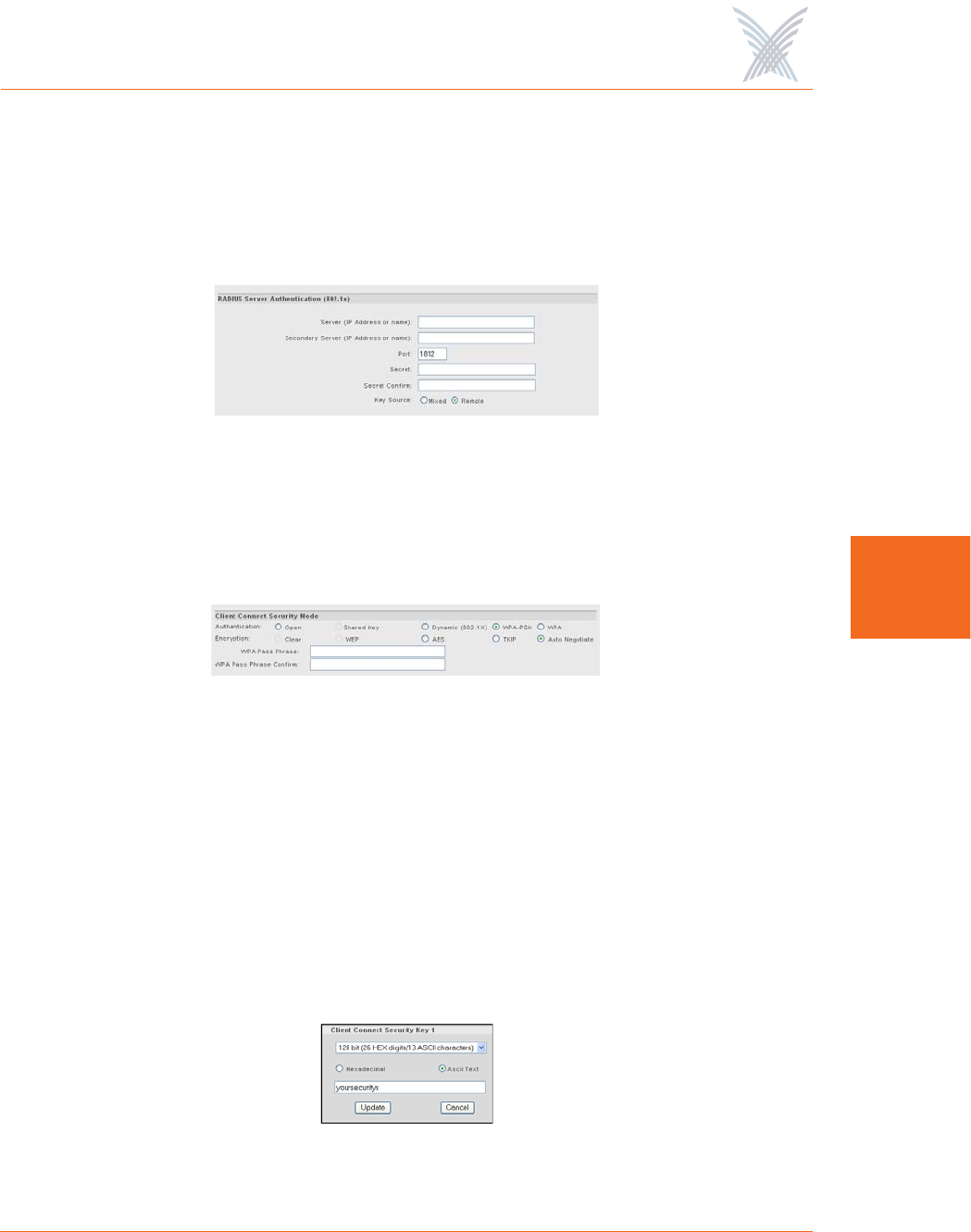
Figure 79. Configuring RADIUS Servers
If you choose WPA-PSK authentication, you must provide a WPA Pass Phrase
and confirm the pass phrase (these fields only appear when WPA-PSK is
selected as the authentication type.
Figure 80. WPA Pass Phrase
◗Client Connect Security Keys
This option allows you to define up to 4 security encryption keys for your
Client Connects. To define a security key, click on the Enter Key 1 (through 4)
button to reveal the security key window, then select either hexadecimal or
ASCII format. Once you have selected the preferred format, choose 64 bit,
128 bit, or 152 bit encryption from the pull-down list and enter your security
key. After entering the key, click on the Update button to add the new key to
the list, or click on the Cancel button to abort the process.
Figure 81. Assigning Client Connect Security Keys
Access / One® Network
106 Managing the Network
5
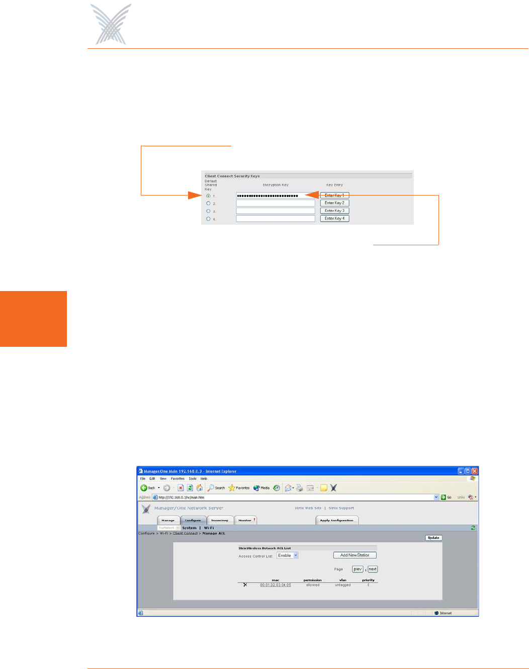
When you add a new Client Connect security key, the system encrypts the
key and the encrypted key appears in the list. You can add up to 4 Client
Connect security keys. After adding security keys, select one of the keys to act
as the default shared key.
Figure 82. Encrypted Security Key
To delete a Client Connect security key, click on the Enter Key 1 (through 4)
button that applies to the key you want to delete. When the pop-up window
appears, choose None from the pull-down list. The selected security key is
removed from the list automatically.
◗Access Control List
This option allows you to configure an Access Control List (ACL) to determine
which user devices (stations) are allowed to connect to your Access/One
Network. To do this, simply click on the Manage ACL button to reveal the
Manage ACL window.
Figure 83. Configuring an Access Control List
Encrypted Key
Default Shared Key
Access / One® Network
Managing the Network 107
5
Choose the preferred access level from the pull-down list. Your options
include:
•Disable: All stations/clients can request association with an SSID in your
Access/One Network. This means that the ACL will not be checked when
a new station attempts to authenticate.
•Enable: All stations/clients are assigned a permission status based on their
MAC address. If the MAC address of the station attempting to gain access
is set to Deny, it will not be allowed to associate with the network. If the
MAC address is set to Allow, or not configured in the ACL, the station will
be allowed network access.
•Strict: Only stations assigned with Allow permissions in the ACL are
granted access to the network, regardless of encryption settings. In
addition, if the entry is configured for an encryption key, the station is
also required to match that key before gaining access. If no ACL entry
exists for a MAC address, it will not be allowed to associate with the
network. The ACL accepts multiple levels of authentication concurrently
so that stations with or without encryption (or shared key authentication)
can be admitted.
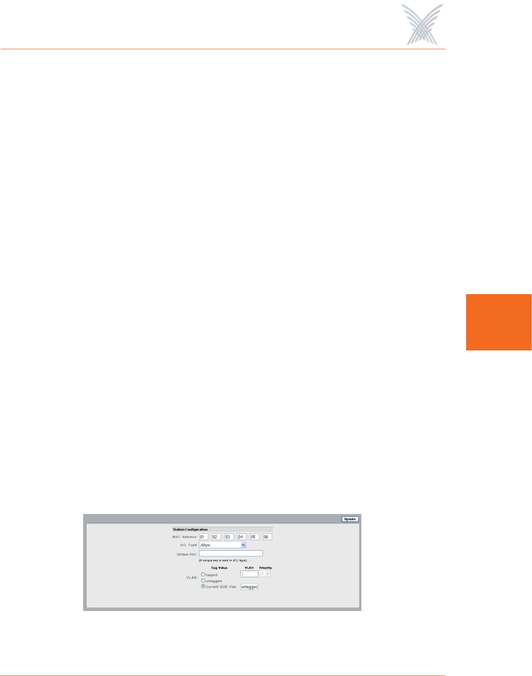
To add a new station, click on the Add New Station button to reveal the Add
New Station window.
Figure 84. Adding a New Station
Changing the ACL mode for wireless stations requires a reboot.
A reboot is also required when adding or deleting ACL entries
at the network level (though not at the module level).

Access / One® Network
108 Managing the Network
5
Enter the MAC address of the new station/client, then choose the ACL type
from the pull-down list. These options include:
•Allow
•Deny
•Default Shared Key
•64 bit (enter 10 digits)
•128 bit (enter 26 digits)
•152 bit (enter 32 digits)
If you choose any of the encryption types, enter the key in the Unique Key
field. Alternatively, you can choose the Default Shared Key and the system
will use the key you assigned as the default in Client Connect Security Keys.
This key will be used for all unicast messages
If you want to assign a VLAN, go to VLAN Security to understand what you
need to do with these fields. If CoS is disabled, your Access/One Network
does not support VLAN priority levels as a queuing mechanism and ignores
them while the frame is in transit through the network. The VLAN mechanism
applies strictly to wireless stations. All Access/One Network devices generate
only untagged traffic.
When you have completed your Access Control List (ACL) configuration,
click on the Update button to apply your changes and return to the Manage
ACL window. You must now click on the Update button in this window, then
click on the Apply Configuration tab to apply all of your ACL changes across
the network. You can now return to the main Client Connect window.
◗Client Connect Privacy
When enabled, this option offers Client Connect privacy by preventing Wi-Fi
users from communicating with each other on the same module. Data from
each Wi-Fi device is sent only to the Ethernet or backhaul ports, requiring a
router or other access device for authentication before allowing the devices
to exchange data. This is important in hotel applications where wireless users
communicate with each other via Guestek or Wayport servers. The default is
disabled.

Access / One® Network
Managing the Network 109
5
◗SSID Shutdown
When enabled, this option shuts down all SSID functionality when network
connectivity is lost. With this feature enabled, if connectivity to the gateway is
lost, the access point will disassociate all attached wireless clients—the client
will know there is a problem and will need to find another access point to re-
establish connectivity with the network. The default is disabled.
◗Discovery Protocols
This option enables the Strix Discovery Protocol (browser plug-in). The
default is enabled. If this option is disabled, the left pane in Manager/One
will not be available and the auto-discovery feature will not function.
◗Client Connect Privacy Tags
This option is used if you want to prevent users from seeing each other on
different modules. For total hotspot privacy, we recommend leaving the
privacy WLAN tags at their default values.
If you want to enable VLAN tag marking for Client Connect privacy (required
for mesh privacy), check this box. If enabled, you must assign the tags (the
defaults are 925 and 926).
After inputting data (or making selections), click on the Update button to update this
page, then click on the Apply Configuration tab to propagate your changes across
the network. If necessary, you can click on the factory default (FD) button in the
toolbar to reset all data on this page to its factory default state.
Network Connect
Network Connect is the infrastructure used by your Access/One Network for a
wireless connection to an existing wired network (small or large). Each node within
the network can utilize a wired Ethernet or wireless module (802.11a or 802.11g)
for node inter-connectivity or connection to a wired legacy network.
Unlike traditional wired Ethernet LAN/WAN connections used by access points and
WLAN switches, Access/One Network’s wireless Network Connect option provides
an advanced level of security between the network node and the LAN/WAN. By
default, the wireless Network Connect link utilizes AES encryption with a secret key
and cannot be compromised.
Access / One® Network
110 Managing the Network
5
When nodes in your Access/One Network are configured for wireless Network
Connect, the system provides several distinct advantages over a typical wireless
network that uses wired connections. These advantages include:
◗Secure networking
◗Self tuning, rapid self-healing, and rogue device detection
◗Scalability
◗Simple installation
◗Lowest cost of deployment
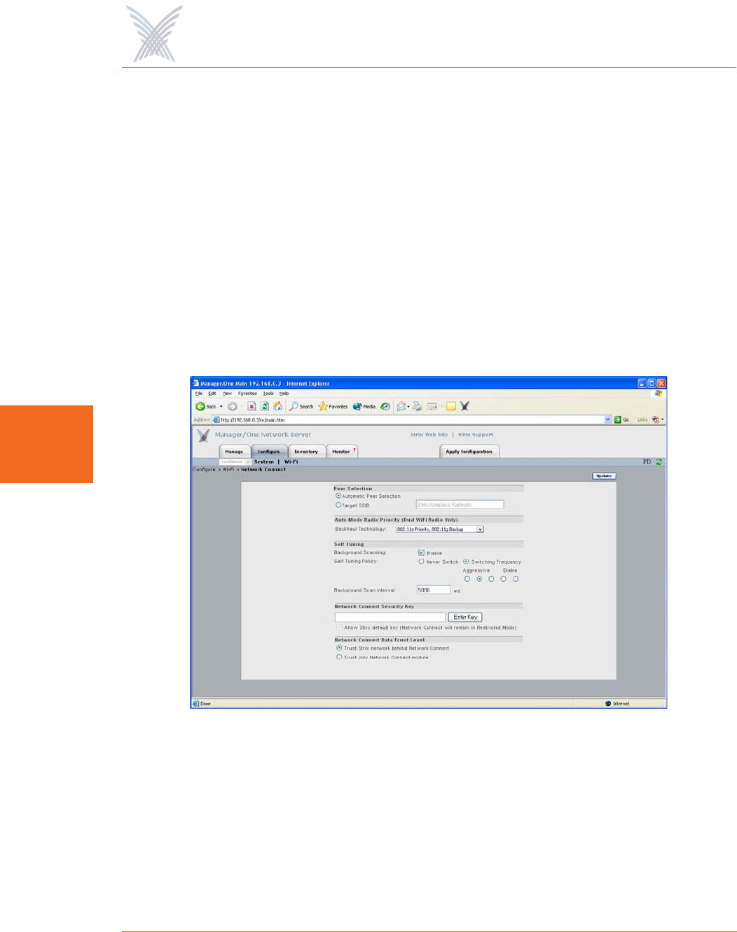
This command allows you to define your Network Connect parameters. The
following graphic shows the Network Connect window set to its default values.
Figure 85. Network Connect
The following options are available with this command:
◗Peer Selection
This option allows you to define peer selection criteria. These include either
Automatic Peer Selection (where your Access/One Network chooses peers
automatically, or selection by Target SSID (you must enter a valid SSID).

Access / One® Network
Managing the Network 111
5
◗Auto-Mode Radio Priority (Dual Wi-Fi Radio Only)
This option allows you to establish a priority for which radio on the dual band
wireless module will operate as a Network Connect in the Auto mode. The
available choices are:
•802.11a Only
•802.11a Priority, 802.11g Backup
•802.11g Priority, 802.11a Backup
•802.11g Only
◗Self-Tuning
This feature allows you to enable or disable Background Scanning and
configure the Self-Tuning Policy. When a Network Connect module first
connects to the network, it performs an initial scan of all available Wi-Fi
channels and generates a list of potential alternate Client Connects that are
reachable. Following the initial scan, the Network Connect continually scans
in the background to maintain the list and enable the system to make the
following intelligent decisions:
•When to drop the current path and select a better path, then connect to
the appropriate node (self-tuning).
•When to select the best path (or detect the loss of a path) and select the
next best path, then connect to the appropriate node (self-healing).
•Which APs are rogue devices.
To fully optimize your network’s ability to self-tune, self-heal and detect
rogue devices, we recommend that the Background Scanning feature is
always enabled (default).
Disabling Background Scanning will prevent Network Connects
from reporting rogue AP devices.

Access / One® Network
112 Managing the Network
5
◗Self-Tuning Policy
You can instruct the system to Never Switch during its self-tuning process, or
establish a Switching Frequency (with 5 possible frequency states between
stable and aggressive). When background scanning is completed, the self-
tuning system determines the best potential client, based on RTD/RSSI scores
and threshold values obtained during the scanning process. Threshold values
become more critical when two Client Connects are very close with their
scores. Normally, this can cause bouncing between the two Client Connects,
but Access/One Network eliminates the bouncing effect by allowing you to
move the threshold switching frequency from aggressive to stable.
◗Background Scan Interval
Enter a value in this field (in milliseconds) to define the interval between
background scans. The default is 5000 milliseconds.
◗Network Connect Security Key
To protect wireless stations associated with each node, your Access/One
Network provides WEP and AES ciphers for encryption and 802.1x remote
authentication. The inter-node Network Connect wireless uplink is protected
with an AES static key to prevent eavesdropping. The factory configured
default key is hidden from view to retain secrecy for a basic network, but this
key can be changed and each network can have its own unique key.
The Network Connect solution for Access/One Network prevents
unauthorized wireless connections from being established to the network by
blocking user traffic in the following two scenarios:
•If the Network Connect is configured for the default network name
(AccessOne), Manager/One forces the administrator to approve/admit the
node to the network before user traffic is bridged to the network.
•If the two nodes that are wirelessly connected (via the uplink) have
different Network Connect security keys configured. However, if the
Allow Strix default key option is enabled then a Network Connect using
the default security key can still connect with a network using a non-
default security key.
Access / One® Network
Managing the Network 113
5
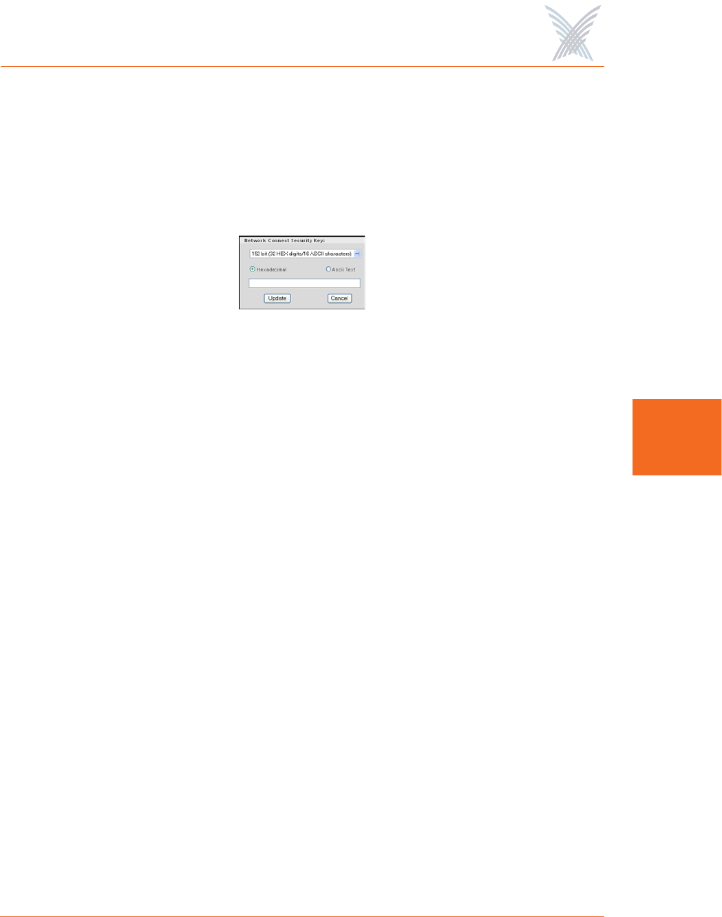
To assign a security key, click on the Enter Key button. In the pop-up window,
select the key entry method (hexadecimal or ASCII text), then enter the key
that will serve as the default key to encrypt packets to be transmitted on a
wireless uplink between nodes. The key length is fixed at 152 bits. After
entering the key, click on the Update button to assign the key and return to
the Network Connect window.
Figure 86. Network Connect Security Key
Enable the Allow Strix default key option if you want to allow Network
Connects with a default key to connect with a network using a non-default
security key. In this case, the network using a non-default security key can
still be managed remotely. The default is enabled.
◗Network Connect Data Trust Level
This feature determines whether the Client Connect will allow traffic from a
Network Connect only (for management purposes), or from devices beyond
the Network Connect module—like a Client Connect on top of it, or Ethernet
devices attached to it. This applies only when a Network Connect uses the
default (non-provisioned) key when associating with a Client Connect.
Choose the preferred trust level policy for the Network Connect from the
following options:
•Trust Strix Network behind Network Connect: Trust the Strix network
behind the Network Connect.
•Trust only Network Connect module: Trust only the Network Connect
module.
After inputting data (or making selections), click on the Update button to update this
page, then click on the Apply Configuration tab to propagate your changes across
the network. If necessary, you can click on the factory default (FD) button in the
toolbar to reset all data on this page to its factory default state.
Access / One® Network
114 Managing the Network
5
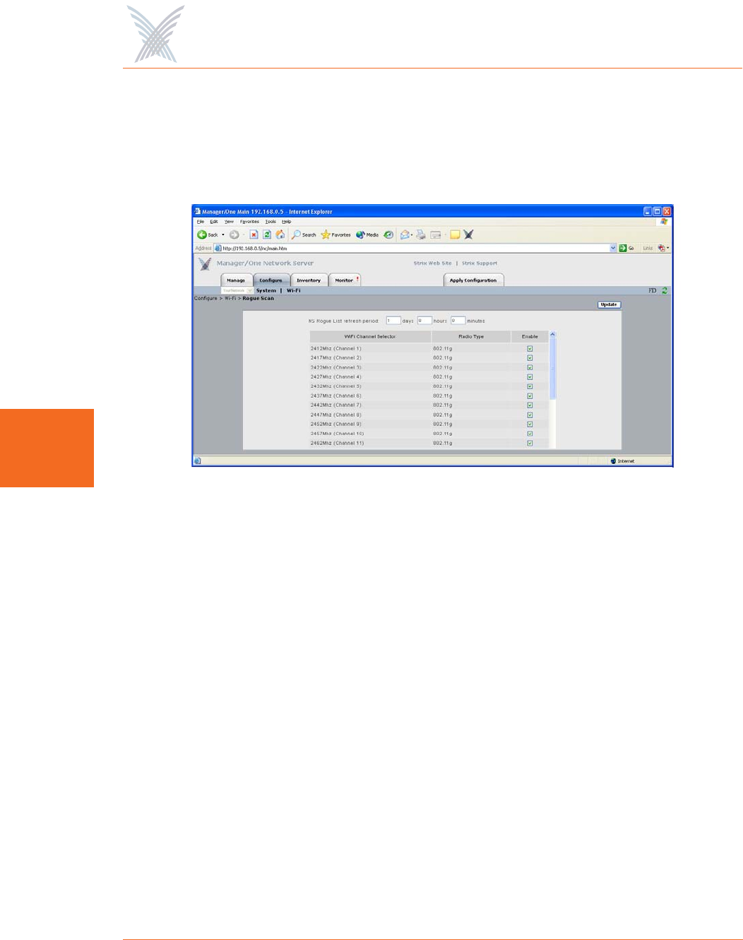
Rogue Scan
This option allows you to define which channels are scanned for rogue devices by
the defined country code. From the configuration window, you can enable or
disable channels.
Figure 87. Rogue AP Scanning
Access / One® Network
Managing the Network 115
5
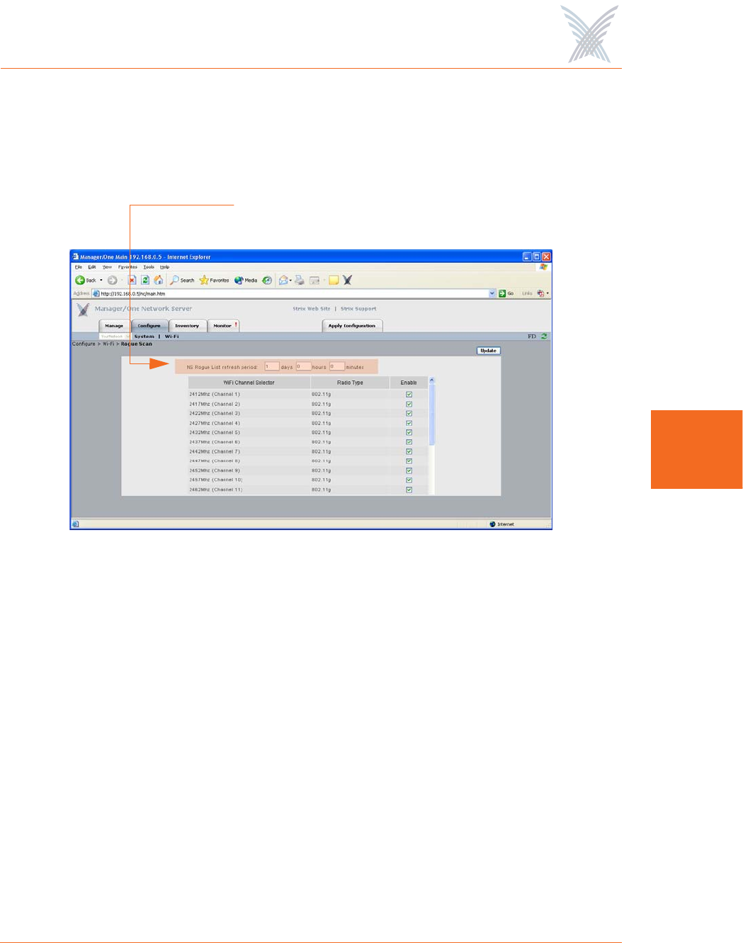
In addition to defining channels, the Rogue Scan configuration window allows you
to define a refresh period—the elapsed time after which the network server refreshes
the rogue device list. The default is 1 day. Making this refresh period too frequent
will adversely impact the performance of the network.
Figure 88. Defining the Refresh Period for the Rogue List
If you make any changes to your channel selections in this window you must click
on the Update button for your changes to take effect, then click on the Apply
Configuration tab to propagate your changes across the network. If necessary, you
can click on the factory default (FD) button in the toolbar to reset all data on this
page to its factory default state.
Define the Refresh Period
Access / One® Network
116 Managing the Network
5
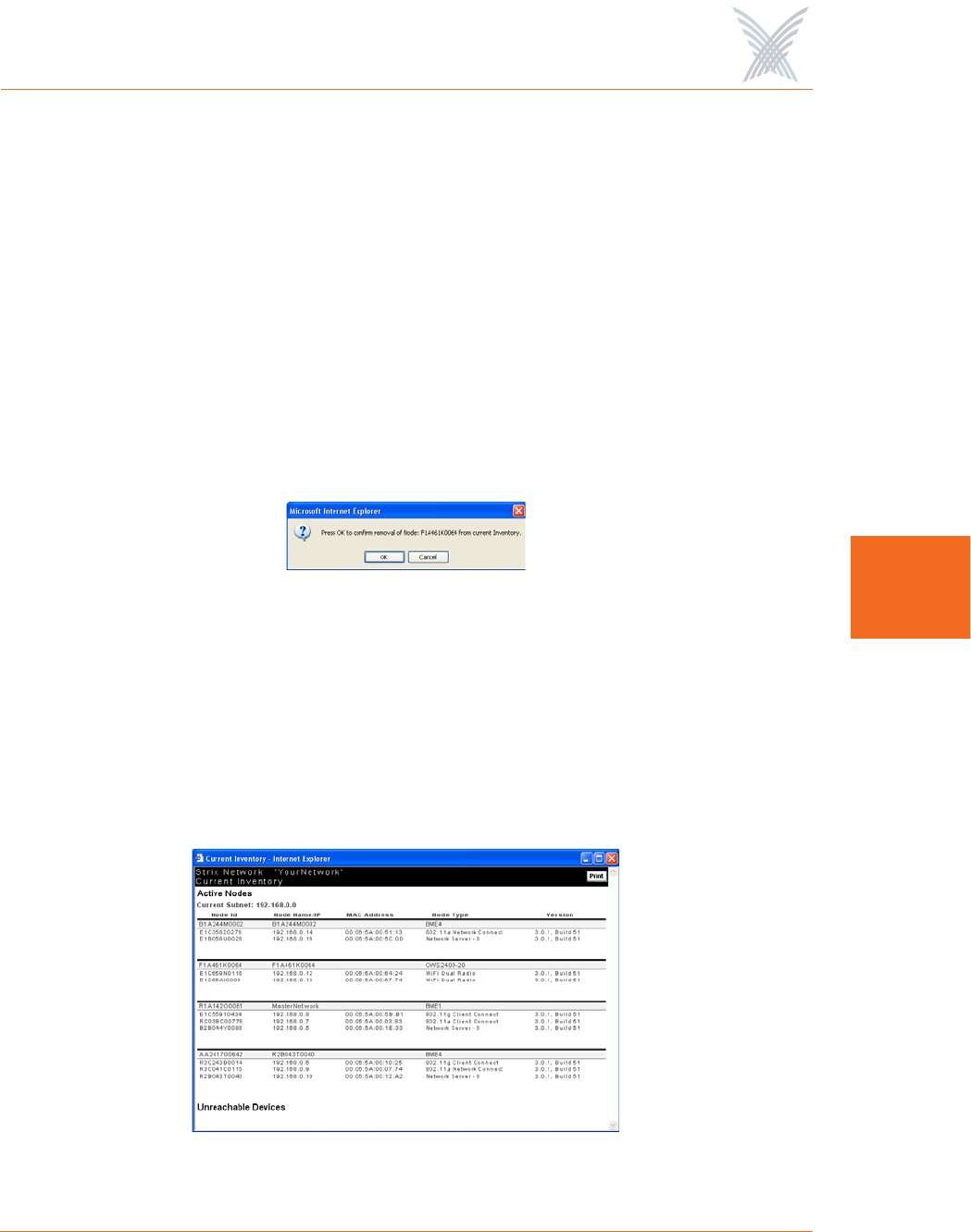
The Inventory Function
This function provides you with an inventory view of your Access/One Network and
includes the following commands:
◗Print Friendly Format
◗Export to CSV
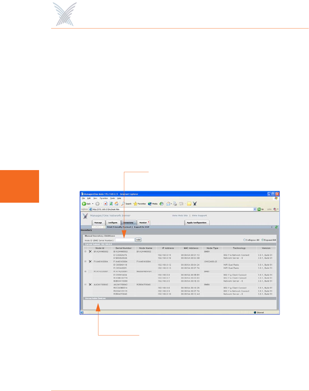
The inventory list is displayed in a tree structure that can be expanded (default) or
collapsed (show nodes only). The structure of the list consists of the Node ID, its
serial number and name, IP address and MAC address, the node type, the
technology it uses, and the current firmware version it is running. To compliment full
two-way authentication, the inventory list is synchronized and maintained between
all Strix devices. See also “Inventory or Auto Discovered” on page 63.
Figure 89. Inventory List
Manual additions (by node serial number)
Unreachable devices are listed here
Access / One® Network
Managing the Network 117
5
The inventory list allows you to manually add nodes, at your discretion. To add a
node to the inventory list, enter the node’s serial number in the Node ID field then
click on the Add button. Nodes that cannot be detected by the network will appear
in the Unreachable Devices frame.
You also have the option of manually deleting nodes from the inventory list. To
delete a node, simply click on the X icon next to the node you want to delete. The
system will then prompt you for a confirmation. Click on the OK button to delete the
selected node, or click on the Cancel button to cancel your request.
Figure 90. Deleting a Node from the Inventory List
Print Friendly Format
This option converts the inventory list into a printer friendly format that can be
printed on standard letter size paper. After converting the inventory list, the system
prompts you for your printer’s destination. To initiate the printing process, click on
the Print button.
Figure 91. Printing the Inventory List
The node’s alphanumeric serial number is case-sensitive, with all alpha
characters being upper case.
Access / One® Network
118 Managing the Network
5
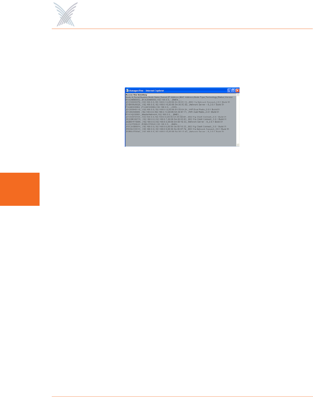
Export to CSV
This option allows you to export the inventory file to a CSV (Comma Separated
Values) format that can be edited within a compatible spreadsheet application, such
as Microsoft Excel®.
Figure 92. CSV File
Importing the CSV File to an Excel Spreadsheet
When the CSV file is created, use the following procedure to import the file into an
Excel spreadsheet for editing.
1. Click in the header of the CSV file to make the CSV window active.
2. Press Ctrl+A to select all text in the CSV file.
3. Press Ctrl+C to copy the selected text to the clipboard.
4. Open a new Excel workbook, then press Ctrl+V to paste the CSV text into a
cell in the workbook.
5. Go to Data in the Excel menu bar and choose Text to Columns... from the
pull-down list.
6. On the first page of the wizard in Excel select the Delimited option, then
click on the Next button.
7. On the second page of the wizard check the Comma check box to enable
the conversion with comma delimiters.
8. On the third and last page of the wizard, click on the Finish button to
convert the raw text into editable columns.
Access / One® Network
Managing the Network 119
5
The Monitor Function
This function provides you with tools that allow you to view your network’s
operation and performance, and includes the following commands:
◗Tools
•AP Monitor
•Network Connect Monitor
•Wireless Client Query
•Rogue Monitor
–Scan
–Ignore All
–Include All
Tools
Clicking on Tools in Manager/One’s toolbar generates a pull-down menu containing
all the commands that are available within the Monitor function.
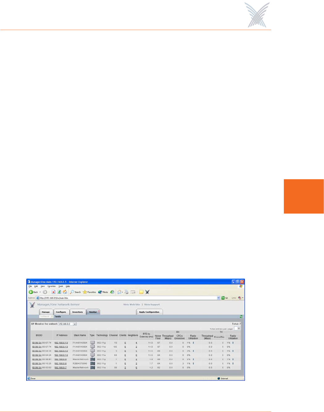
AP Monitor
The AP Monitor provides a snapshot in table form of all active Client Connect
devices on a selected subnet.
Figure 93. AP Monitor (Default View)
Access / One® Network
120 Managing the Network
5
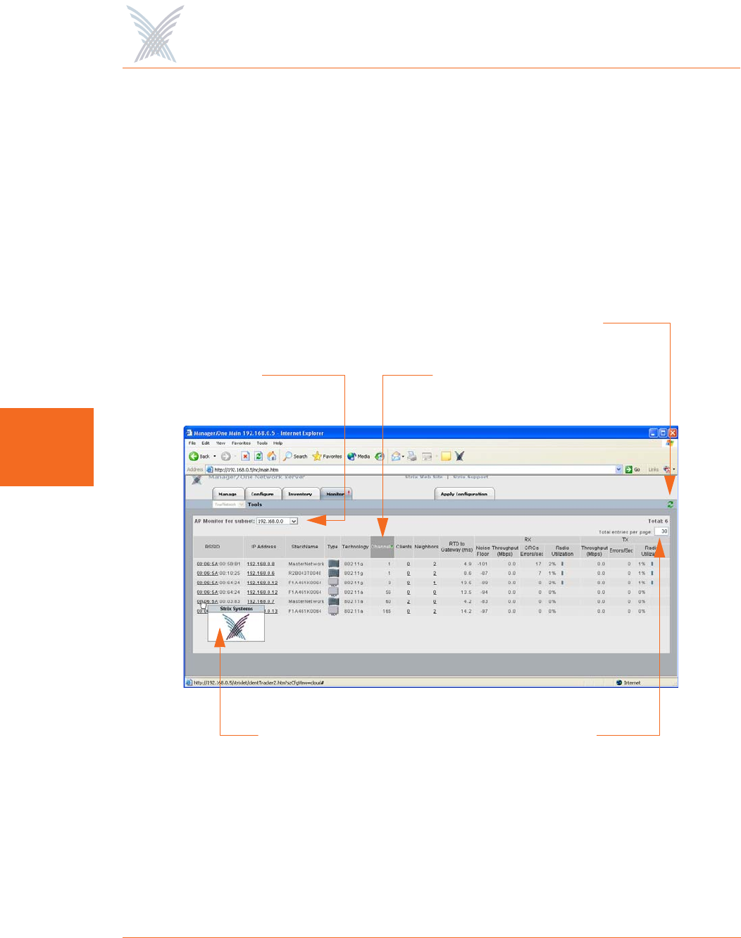
The table displayed in the AP Monitor window can be customized to show a defined
number of entries in the table, and the table can be sorted in either ascending or
descending order based on any selected column. For example, if you want to sort
the table by channel, click in the column header for Channel—the table is then
sorted according to the channels used by the Client Connects.
The target subnet can also be changed by selecting another subnet (as long as the
subnet exists in the pull-down list). In addition, the table offers instant access to the
assigned BSSID information for each node and you can log in to any node by simply
clicking on its IP address (all links are underlined).
Figure 94. An Overview of Monitor Tables (AP Monitor)
To define how the table is sorted, simply click in a column header to toggle between
ascending or descending for the data in that column to become the primary sort
criteria. The data in the AP Monitor table can be refreshed at any time.
BSSID Information
Sorted by ChannelSubnet
Refresh
Total Entries
Access / One® Network
Managing the Network 121
5
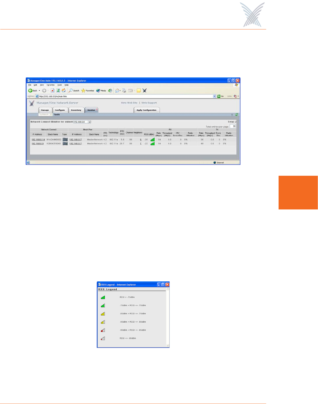
Network Connect Monitor
The Network Connect Monitor provides a snapshot in table form of all active
Network Connect devices on a selected subnet.
Figure 95. Network Connect Monitor
Although the displayed data is different, the organization of tables in all monitors is
the same. For information about how to define the sort criteria within the Network
Connect Monitor table, see Figure 94.
The only difference in the navigational content between the Network Connect
Monitor and the AP Monitor is the Network Connect Monitor also includes an
information button (i) in the top right corner of the window. Clicking on this button
generates the RSSI Legend pop-up window that provides a reference for the icons
displayed in the RSSI (dBm) column.
Figure 96. RSSI Legend
Access / One® Network
122 Managing the Network
5
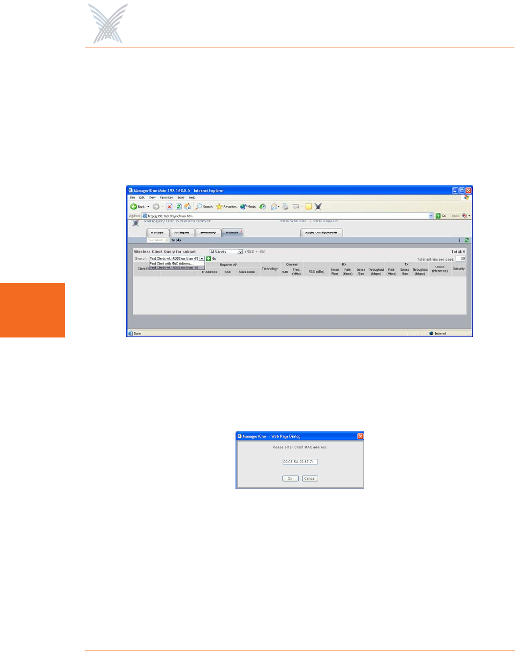
Wireless Client Query
The Wireless Client Query Monitor provides a search tool that allows you to run a
query through the network and locate Wi-Fi clients based on the following search
criteria:
◗Find a client based on a specific MAC address
◗Find clients with an RSSI value of less than -85 dBm
Figure 97. Wireless Client Query Monitor
If you choose to search for a client based on its MAC address, the system prompts
you for the address. After entering the MAC address, click on the OK button to start
the search.
Figure 98. MAC Address Prompt
Although the displayed data is different, the organization of tables in all monitors is
the same. For information about how to define the sort criteria within the Wireless
Client Query Monitor table, see Figure 94. And similar to the Network Connect
Monitor, the Wireless Client Query Monitor also includes the information button (i)
in the top right corner of the window. Clicking on this button generates the RSSI
Legend pop-up window (see Figure 96).