Strong Frontier Sdn Bhd TE800-R Tire Pressure Monitor System User Manual Tire Pressure Monitoring System
Strong Frontier Sdn. Bhd. Tire Pressure Monitor System Tire Pressure Monitoring System
Contents
- 1. Users Manual
- 2. Users Manual Revised
Users Manual Revised

08-09-01-009-0
OWNER’S MANUAL
TABLE OF CONTENTS
Notices ……………………………………………………………………………..….……………...
FCC Notice
System Scope of Use and Warnings
System Installation and Usage
Reacting To Alerts
Use of Chemicals
Page 1
1. Technical Specifications …………………………………………………………………………….
Sensor/Transmitter Module
Display/Receiver Module
Page 2
2. Components Part List ……..………………………………………………………………………... Page 3
3. Getting Started ……………………………………………………………………………………….
How it works
Handling Alerts
Page 4
4. Sensor/Transmitter Module …………………………...………………………….………………...
Installation
Tools Required
Installing Sensor/Transmitter Module….………………………………………………….
Page 5
Page 6
5. Display/Receiver Module ………………………………...…………………………………………
LCD Display
Installation
Recommended Installation for Display / Receiver Module.……………………………...
Page 7
Page 8
6. Programming ………………………………………………………………………………….……….
Display Mode (S-1)…………………………………………………………………………..
Programming Threshold Setting (S-2)……………………………………………………..
Sensor ID Exchange
Mode (S-3).………………………………………………………….
Sensor ID Learning
Mode (S-4)….…………………………………………………………
Turn Backlight On/Off (S-5)……...………………………………………………………….
Activate Spare Tire On/Off (S-6)..……………….…………………………………………
Page 9
Page 10
Page 11
Page 12
Page 13
Page 14
Page 14
7. Troubleshooting ………………………………………………………………………………………. Page 15
8. Appendix & Glossary ………………………………………………………………………………… Page 15
9. Annex ………………………………………………………………………………………………….. Page 16
The manufacturer reserves the right to change the contents of this manual at any time without prior notice. The information
contained in this manual is proprietary and must not be reproduced without prior consent from the manufacturer.
i

NOTICE
FCC Notice
This device complies with Part 15 of the FCC Rules. Operation is subject to the following two conditions: (1) this
device may not cause harmful interference, and (2) this device must accept any interference received, including
interference that may cause undesired operation.
This equipment has been tested and found to comply with the limits for a Class B digital device, pursuant to Part 15
of the FCC Rules. These limits are designed to provide reasonable protection against harmful interference in a
residential installation. This equipment generates, uses and can radiate radio frequency energy and, if not installed
and used in accordance with the instructions, may cause harmful interference to radio communications. However,
there is no guarantee that interference will not occur in a particular installation.
If this equipment does cause harmful interference to radio or television reception, which can be determined by
turning the equipment off and on, the user is encouraged to try to correct the interference by one or more of the
following measures:
• Reorient or relocate the receiving antenna.
• Increase the separation between the equipment and receiver.
• Connect the equipment into an outlet on a circuit different from that to which the receiver is connected.
Caution: Any changes or modifications in construction of this device which are not expressly approved by the party
responsible for compliance could void the user’s authority to operate the equipment.
System Scope of Use and Warnings
Tire Pressure Monitoring System (TPMS)
This system is a sensing device designed to measure and display tire operation and/or activate an alert to the driver
when pressure and temperature irregularities are detected. It is the responsibility of the driver to react promptly and
with discretion to alerts. Abnormal tire inflation pressure should be corrected at the earliest opportunity.
System Installation and Usage
Use of the TPMS requires that it has been properly installed by qualified personnel according to the instructions here.
This system is suitable for use in passenger car, SUV and 4X4 tires up to maximum cold inflation pressure of 500
Kpa (or 73 Psi).
Reacting to Alerts
When an alert or warning is received, reduce vehicle speed and proceed to a safe stop location where the tire can
be inspected and/or serviced.
The low-pressure alert indicates that the air pressure has dropped to a selected minimum and a high-temperature
alert indicates that the temperature of the tire content has surpassed the threshold value set.
Use of Chemical
Temporary resealing or re-inflation products containing internal sealants or propellants in any tire assembly may
adversely affect the operation of the Sensor/Transmitter.
Page 1

1. TECHNICAL SPECIFICATION
Sensor / Transmitter Module
Operating Temperature Range -40°C to +125°C
Operating Humidity 100%
Weight 32 gram
Size (LxWxH) 71 mm x 36 mm x 21 mm
Battery Life (Projected) 5 years in normal use
Transmitting Frequency 433.92 MHz
Transmitter Activation By pressure change
Table 1
Display/Receiver Module
Power Supply 9 ~ 15 V DC
Current Consumption 18mA nominal, 130mA during alert @ 12V DC.
Operating Temperature Range -40°C to +85°C
Weight 93 gram
Size (LxWxH) 18mm x 125mm x 33mm
Receiving Frequency 433.92 MHz
Monitored Temperature Range -40 ~ 125°C (-40 ~ 257°F)
Monitored Pressure Range 0 ~ 500 Kpa (Accuracy: ± 10 Kpa)
0 ~ 73 Psi (Accuracy: ± 1.5 Psi)
Table 2
Page 2
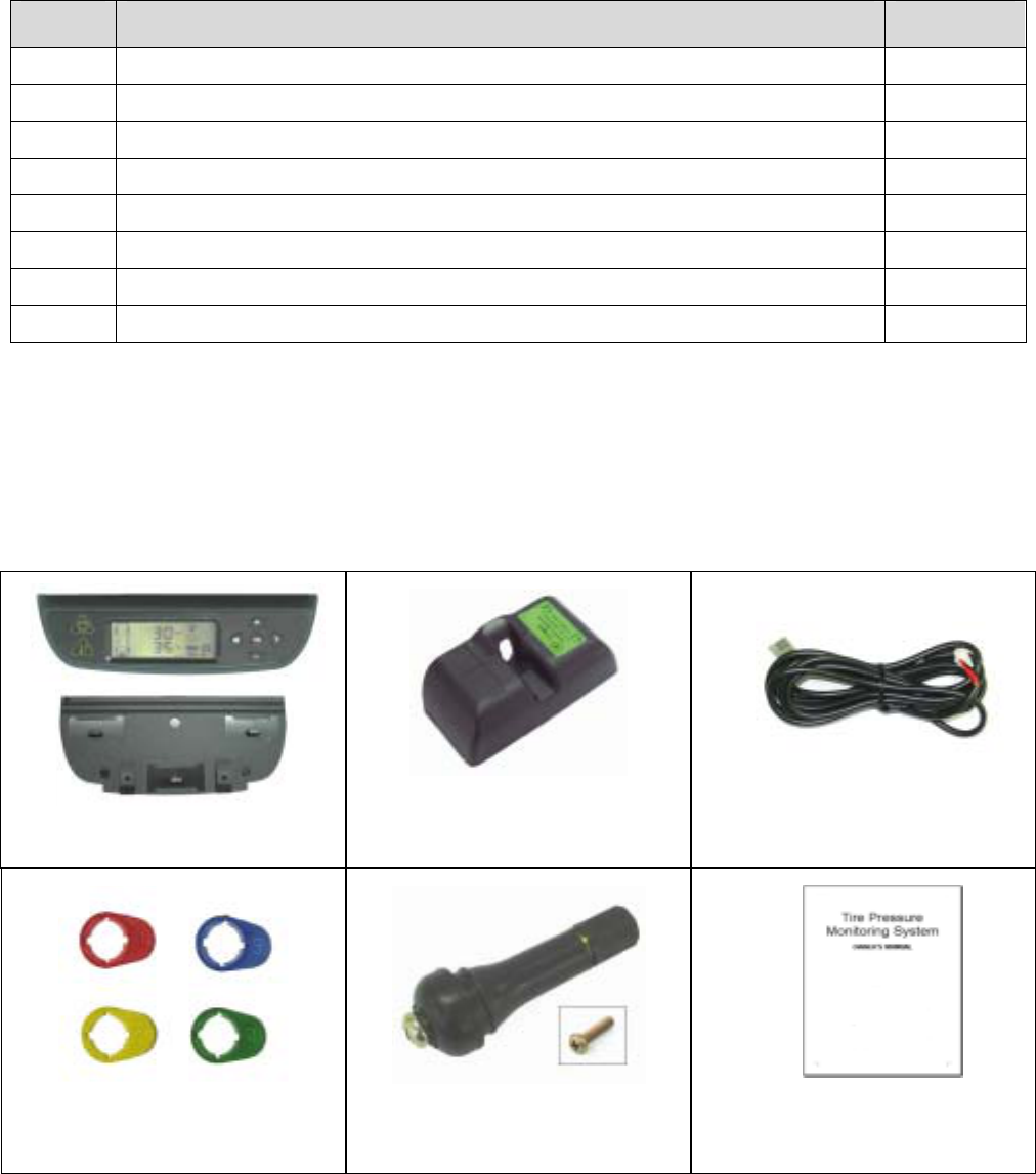
2. COMPONENTS PART LIST
After unpacking, ensure that all the parts listed below are available. Should any part(s) is/are found missing, please
return to your dealer and get a complete replacement set.
Item Description Quantity
1 TPMS DISPLAY MODULE ASSY 1
2 DISPLAY MODULE BRACKET 1
3 TPMS SENSOR MODULE ASSY * 4
4 TPMS POWER CABLE ASSY 1
5 SENSOR TAGS (YELLOW, RED, BLUE, GREEN) 4
6 TIRE VALVE ** 4
7 VALVE SCREW M5 x 20 ** 4
8 TPMS OWNER'S MANUAL 1
Table 3
* Optional 1pc for Spare Tire available
** Use only provided tire valve and screw.
Item 6 – Tire Valve with internal thread M5
Item 7 – Valve Screw M5 x 20 with centre holes
For replacement parts, quote the description, part code and quantity required when ordering.
Item 1, 2
Item 3
Item 4
Item 5
Item 6 & 7
Item 8
Page 3
3. GETTING STARTED
How it works
Pressure and temperature information are sent to the Receiver and displayed on the LCD display. When an under-
inflated, over-inflated or over-heated tire is detected, the Receiver will emit an audible warning and activate the
backlight to warn the driver. The alerts depend on threshold value set for pressure and temperature. Either the
factory or manual preset value can be selected.
Handling Alerts
When any of the tires is not within the threshold limits (e.g. under inflated or over heated, the following will occur:
• An audible warning will be activated for a period of 10 seconds at the first occurrence.
• The backlight of the LCD display would be activated for 20 seconds at the first occurrence.
• Low/High Pressure Alert: Pressure Alert indicator (Yellow) of the module turn On permanently.
• Initial Low Pressure Alert: Pressure Alert indicator (Yellow) of the module will blink.
• High Temperature Alert: Temperature Alert indicator (Yellow) of the module turns On permanently.
• Tire icon will blink at the faster rate.
The above conditions will persist until the threshold returns to their corresponding preset value.
All TPMS unit comes with the following factory-preset value:
a. Initial Low Pressure Alert when tire pressure is greater than 120Kpa but lesser or equal to 170Kpa (50Kpa
before Low Pressure Alert)
b. Low Pressure Alert when tire pressure is lesser or equal to 120 Kpa (23 Psi)
c. High Pressure Alert when tire pressure is greater or equal to 300 Kpa (44 Psi)
d. High Temperature Alert when tire temperature is greater than 80ºC (176ºF)
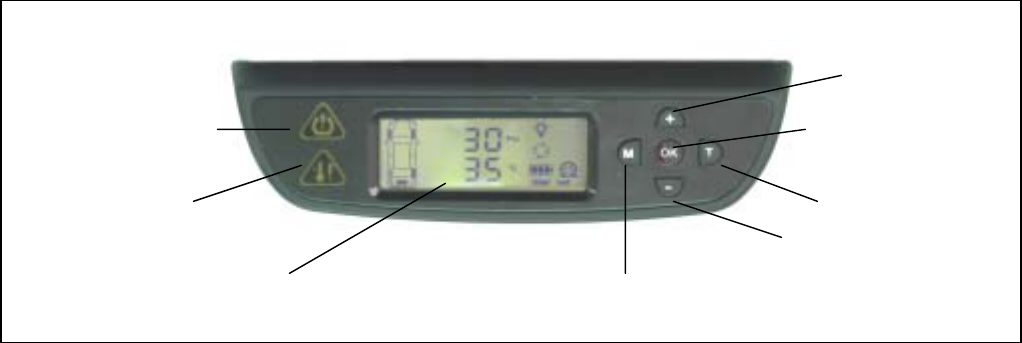
Pressure Alert Indicator
Temperature Alert
Indicator
LCD Display
Increment Value /
Kpa / Bar / Psi
OK key / Power On/OFF
Tire Select
Decrement Value /
°C / °F
Mode Select
Figure 1 Display/Receiver Module
Page 4
4. SENSOR/TRANSMITTER MODULE
Installation
Caution: Qualified personnel must perform the following installation
procedures to ensure that the Sensor/Transmitter Module are
properly installed and undamaged. It does not include any standard
procedures normally required in the process of replacing a tire but
due care should be taken to ensure that the sensors are not
damaged.
Tools Required
• Tire changing equipment
• Tire balancing equipment
• Philip Screwdriver
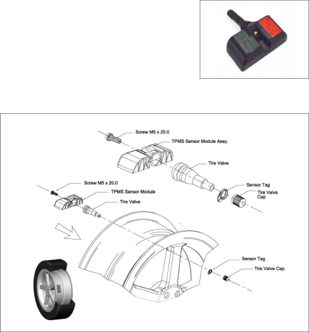
Figure 2 Sensor Module
Figure 2a – How to Install Sensor Module with Tire Valve
Page 5
Installing Sensor/Transmitter Module
Note
The following is suggested installation sequence:
Transmitter Wheel Position
Red (1) Left Front
Yellow (2) Right Front
Blue (3) Right Rear
Green (4) Left Rear
White (5) *Spare Tire
Table 5
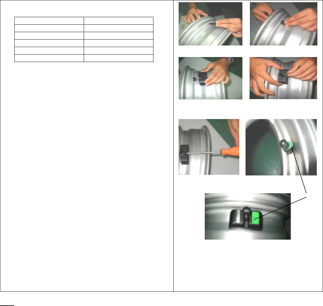
• Remove the original tire valve from tire rim.
• Insert the provided tire valve into rim valve hole.
(Figure 3a & Figure 3b.)
• Position the Sensor/Transmitter rear to the mounted
tire valve. (Figure 4),
• Insert the provided screw to the Sensor as shown in
figure 5 and screw the Sensor to the tire valve.
(Figure 6). The tire valve will be the reference
position of the sensor in order not to damage the
sensor when removing tire from the wheel. Ensure
that the screw is properly tightened to hold the
sensor.
• Attach the corresponding color tag to the valve stem
and secure it with the valve cap by carefully twisting
the tag onto the valve stem. See Figure 7a and
Figure 7b.
• Proceed to mount the tire onto the wheel.
• Ensure that the tires are properly re-balanced.
*Optional Part
Figure 3a Figure 3b
Figure 4 Figure 5
Figure 6 Figure 7a
Figure 7b
# = The tag (Figure.7a) has the same color and
number as the same as the sensor label
(Figure.7b).
#
Ensure that each of the color tag correspond to the color label on the sensor. Refer Table 5 for the corresponding
sensor tag to tire. Keep the colored sensor tag on the valve stem for installation and tire rotation.
Page 6
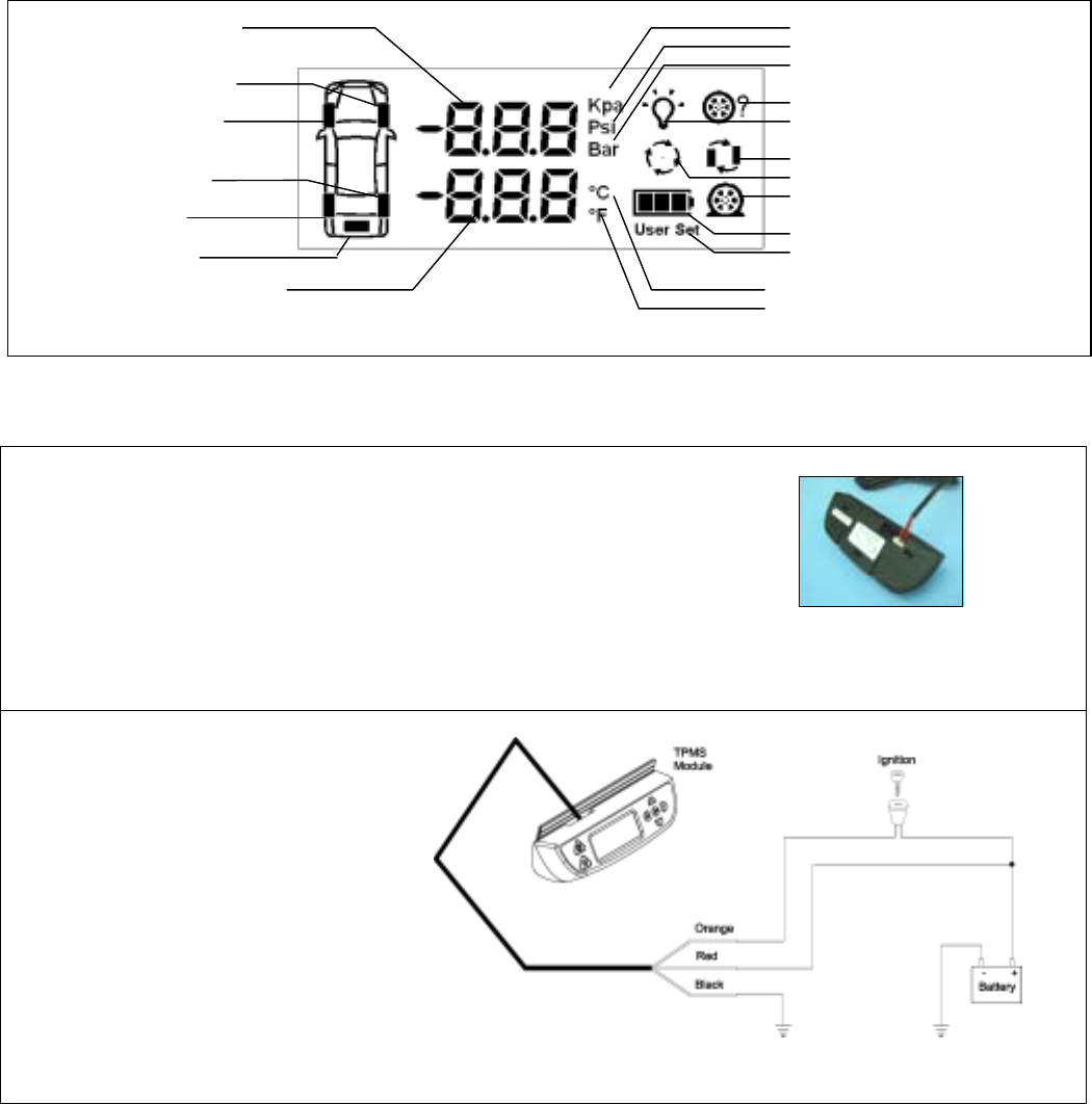
5. DISPLAY/RECEIVER MODULE
Sensor Battery Status
User setting selected.
ID learning mode.
Backlight selection.
Temperature in °C.
Temperature in °F
ID exchange mode.
Tire monitor mode.
Pressure alert icon.
Pressure in Kpa
Pressure in Psi
Pressure in Bar.
Measured Temperature
Readout
Rear Right Tire
Front Right Tire
Measured Pressure
Readout
Front Left Tire
Rear Left Tire
Spare Tire
Figure 8 LCD Display
Installation
1. Insert the Power Supply Cable connector into Receiver socket,
which is located at the top rear. (Figure 9 &10).
2. Connect the other end of the Power Supply Cable to the vehicle
+12VDC, Ground and ACC.
Figure 9 Connection of Power Cable
RED color wire to vehicle +12V DC,
BLACK color wire vehicle Ground,
ORANGE color Wire to vehicle ACC,
Figure 10 Wiring Diagram
Page 7
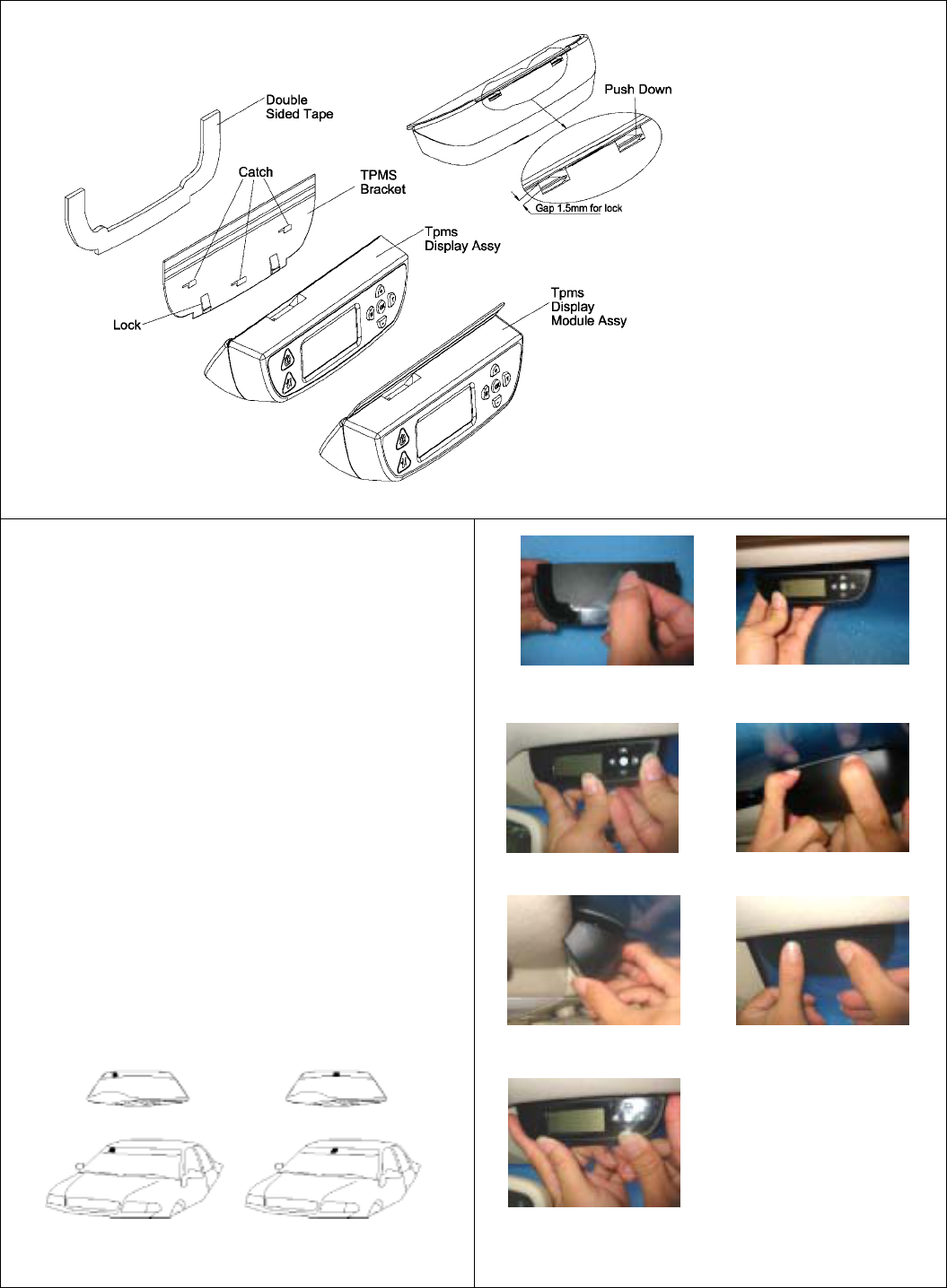
Recommended Installation for Display/Receiver Module and Bracket
Figure 11
1. Determine the desired location for Display/Receiver
Module. Refer Figure. 12 for possible locations
2. Peel off the film covering the piece of black adhesive
double-sided-tape film on the back of the display
bracket. (Figure 13)
3. Mount the Display Module to the desired location.
(Figure 14)
4. Apply pressure around the Display/Receiver Module
for maximum mounting of the module to the car
windscreen. (Figure 15)
5. If the module did not fix well to the windscreen, take
out the Display module from the bracket. (Figure 16
and Figure 17)
6. Apply pressure around the bracket panel for
maximum mounting of the bracket to the car
windscreen. (Figure 18)
7. Install back the Display/Receiver module to the
bracket. (Figure 19)
Figure 12
Figure 13 Figure 14
Figure 15 Figure 16
Figure 17 Figure 18
Figure 19
Page 8
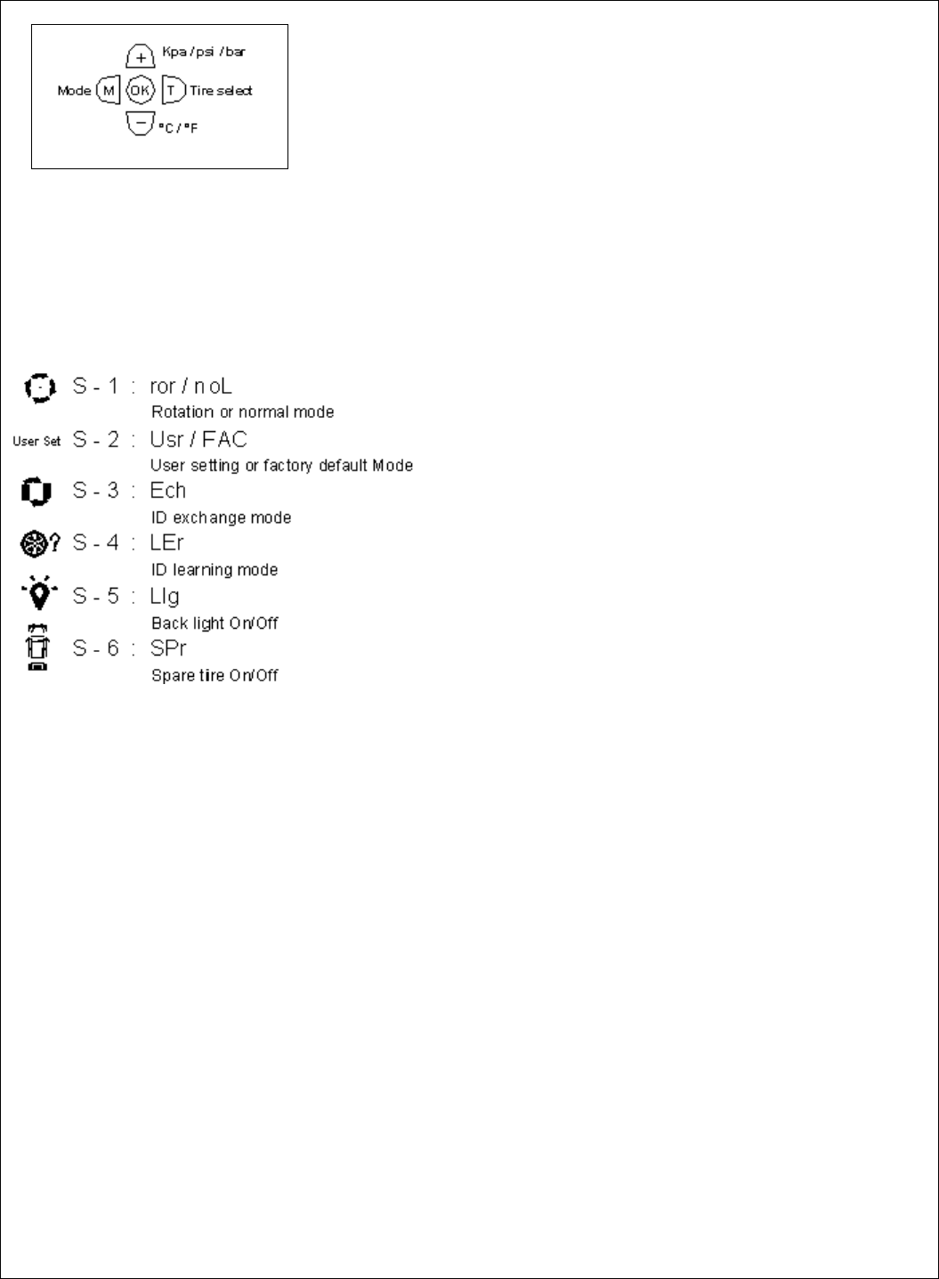
6. PROGRAMMING
Figure 20
To Enter Programming mode Main Menu
1. Ensure that the power is switched ON
2. Press and hold [M] button for 3 sec or more
In programming mode toggle the [+] or [-] button for desired programming mode from S-1 to S-6.
To accept the desired programming mode press [OK] button.
To Quit Programming Main menu Display mode, press and hold [M] button for 3sec or more.
Page 9
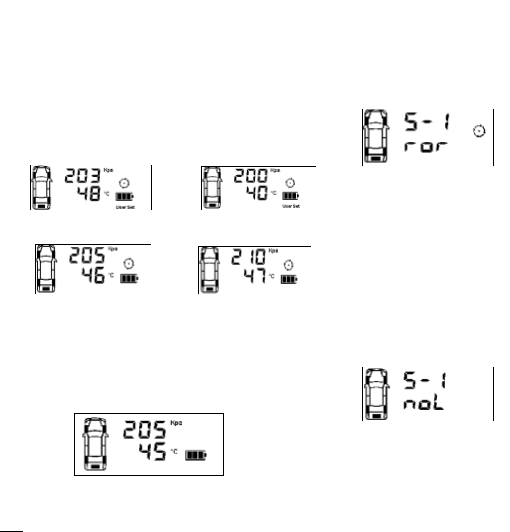
Display Mode (S- 1)
Press [OK] to enter programming display mode. ‘ror’ or ‘noL’ will blink to indicate that it is ready to accept
changes. Toggle [+] or [-] button to alternate between Rotation Mode and Normal Mode.
Rotation Mode
Each of the tires will be ‘scanned’ for the reading. The rotation will begin
from Front Left tire, followed by Front Right Tire, Rear Right Tire, Rear Left
Tire and the cycle will begin again with the Front Left Tire. This is indicated
by a blinking tire icon.
J
K L
I
Figure 22
Figure 21
Rotation Mode Activated
Normal Mode
In the normal mode, the display will always show information of the tire with
the lowest pressure value. The rotation mode tire symbol will be disabled
indicating the selected mode is normal mode. (Refer to figure 23 & 24)
To view information of other tires, press [T] button.
Figure 24
Figure 23
Normal Mode Activated
Note
Value shown is for reference only.
Page 10
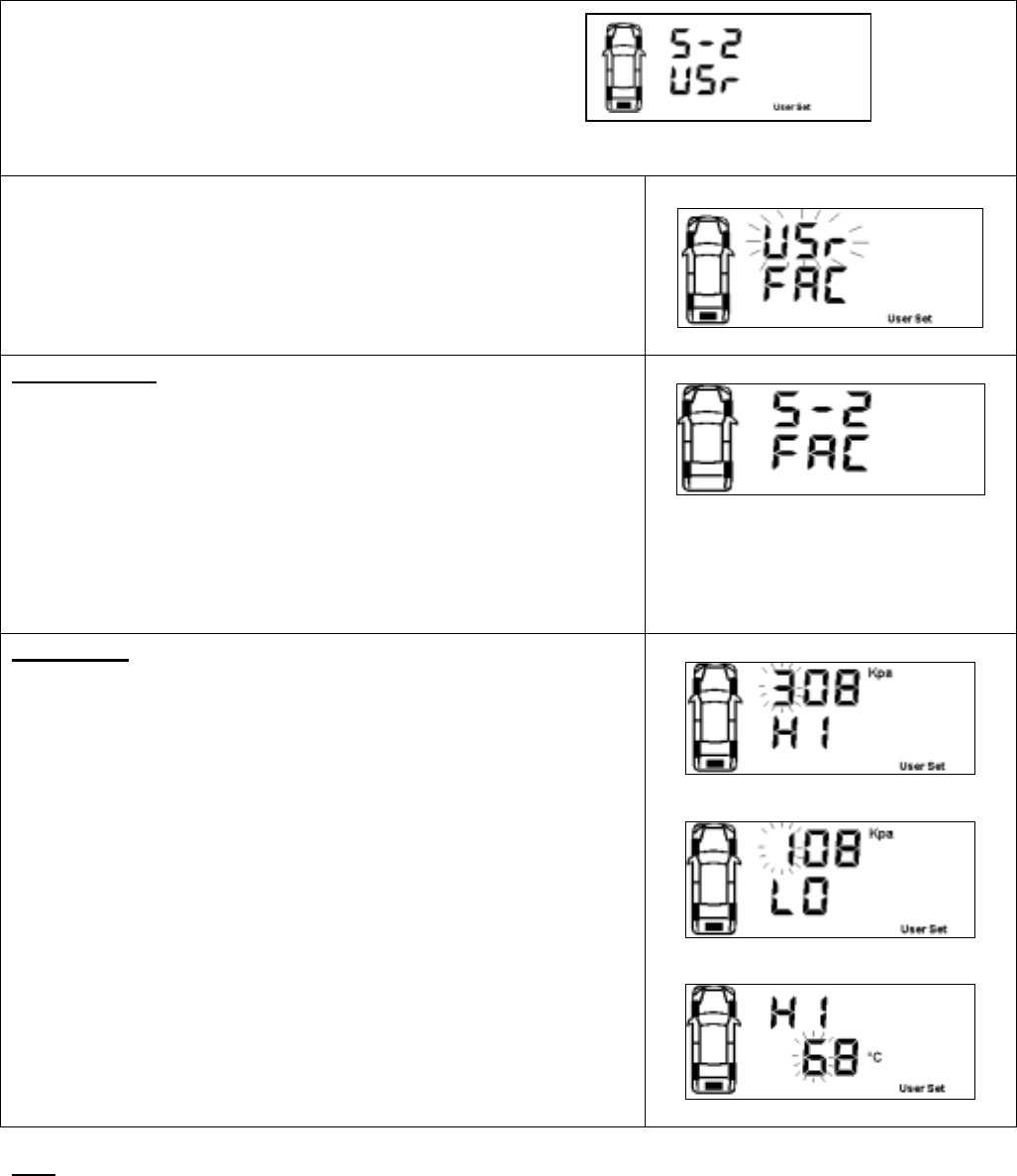
Programming Threshold Setting (S- 2)
Press [OK] to enter the Threshold setting mode.
There are two available threshold setting mode available,
1. User setting (USr)
2. Factory Default (FAC) Figure 25
Upon entering this mode, the selected threshold setting mode will
blink, indicating that the currently selected mode and it is ready to
accept changes of the mode. Pressing the [ + ] button or [ - ] button to
toggle the mode to USr or FAC. (refer figure 26)
Figure 26
Factory Default
To use the factory default mode, toggle [+] or [-] button till the ‘FAC’
setting blinks.
1. Press [OK] to view the factory default for High Pressure Alert,
2. Press [OK] second time for Low pressure Alert and press [OK] the
third time for Temperature threshold alert. Finally press [OK] again
to accept and select the Factory default setting.
Note
All TPMS unit comes with a factory-preset value of 120 Kpa (23 Psi)
for the Low Pressure Alert, 300 Kpa (44 Psi) for High-pressure alert
and 80ºC (176ºF) for the High Temperature Alert.
Figure 27
User Setting
1. To use the User setting mode, toggle [+] or [-] button till the ‘USr’
setting blinks.
2. Press [OK] to enter user setting programming mode. The 1st digit
of High Pressure alert will blink. (Figure 28)
3. Toggle [+] or [-] button to make the value changes.
4. Press [OK] to confirm the changes. The next digit will blink to
indicate that it is ready to accept new input.
5. Repeat steps 3 and 4 to adjust the value of other digits on the LCD
display.
6. Repeat step 2 to step 5 for both Low Pressure Alert (Figure 29)
and High temperature alert (Figure 30).
Note
For low and high pressure alert, the maximum limit is 399Kpa (58 Psi)
while for temperature; the maximum limit is 99ºC (210ºF).
To confirm the selected value, press the [OK] button to save it.
Figure 28
Figure 29
Figure 30
Note
1. Value shown is for reference only.
2. The setting of Manual Threshold Setting can only be done in Kpa (Pressure) and ºC (Temperature).
Refer to Annex 1 & 2 for conversion between the units.
Page 11
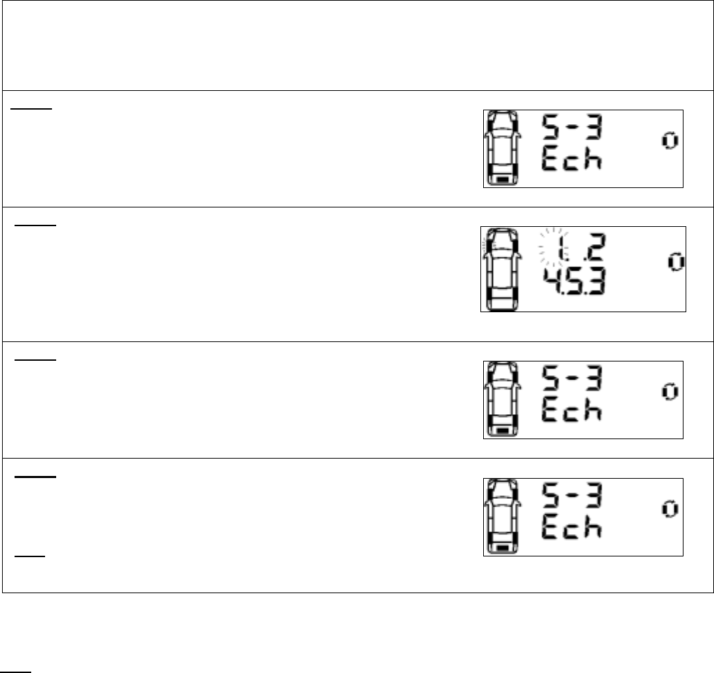
Sensor ID Exchange
Mode (S- 3)
After rotation of tires, the Sensor ID data in the receiver must be changed accordingly to ensure that it indicates
the correct tire when there are any irregularities.
Step 1
Press [OK] button to enter ID Exchange mode.
Figure 31
Step 2
The Front left tire icon and its corresponding ID digit will blink.
1. Use [+] and [-] button to change the selected Sensor ID digit.
2. Press [OK] to confirm the changes and the next ID digit will blink
accordingly.
3. Repeat step 1 and 2 for all other ID digits.
4. The ID number ‘5’ will only be available if the spare tire setting is
‘ON’
Figure 32
Step 3
Press [T] button to quit the ID Exchange mode without saving and
return back to Programming Main menu display.
Figure 33
Step 4
The receiver will return back to Programming Main menu display and
that complete the process of exchanging Sensor ID data in the
receiver.
Note
The receiver will not save the information if any of the tires are found
to have identical Sensor ID.
Figure 34
Note
1. Value shown is for reference only.
Page 12
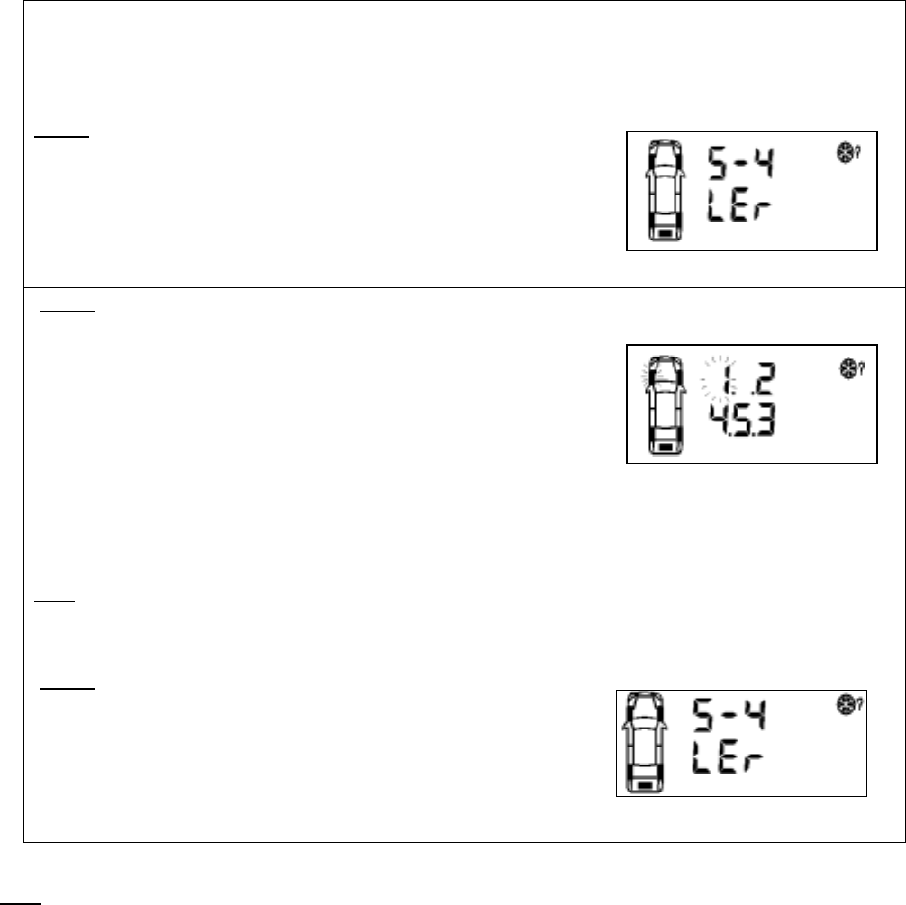
Sensor ID Learning
Mode (S- 4)
For programming of a new receiver unit with ID Learning Mode, refer to the following steps.
Step 1
Press [OK] button to enter the ID learning Mode.
Figure 35
Step 2
1. The front left tire icon will blink. Toggle [+] or [-] button to
select the desired tire and press [OK] to accept the desired
location. The corresponding tire ID number blinks (once per
second) to indicate that it is ready to accept new Sensor ID
input.
2. Inflate or deflate the corresponding tire by at least 28Kpa
(4Psi).
3. When the new ID code is received, the tire icon will blink at a
faster rate (twice per second); the ID number stops blinking
and the module will beep for 5 second.
4. Press [OK] button to save the sensor ID.
5. Repeat Step 1 to 3 for other tire sensor(s) that needs to be
replaced.
Note
ID ‘5’ will only be able to receive sensor signal if the Spare Tire
setting is ON. (Refer to Spare Tire On/Off
Mode (S- 6))
Figure 36
Step 3
Press [T] button to return to Programming Main menu display.
Figure 37
Note
1. The receiver will not save any identical Sensor ID.
2. Value shown is for reference only.
Page 13
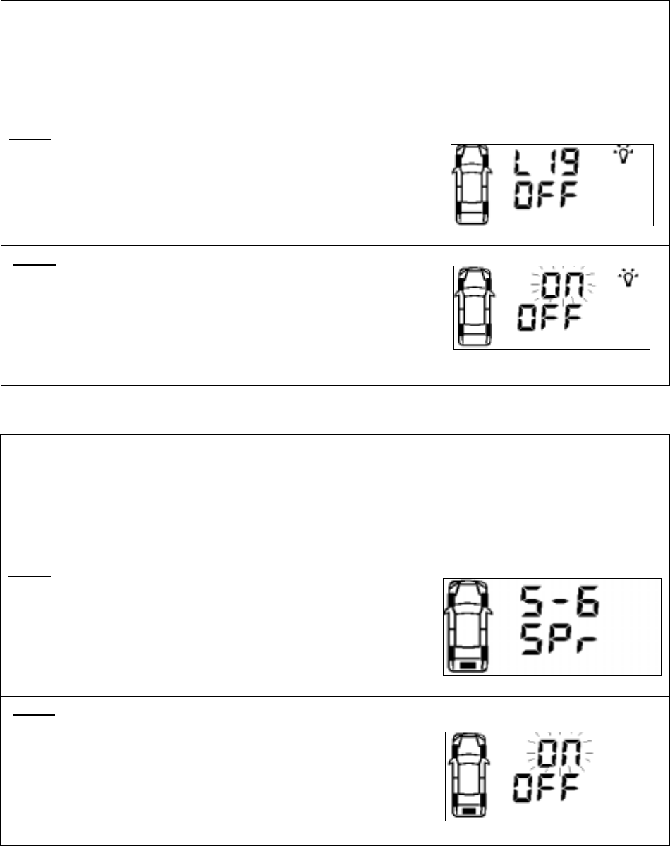
Turn Backlight On/Off (S- 5)
For programming backlight setting, refer to the following steps.
1. Backlight On (Permanent On)
2. Backlight Off (Auto)
Step 1
Press [OK] button to enter Backlight programming mode.
Figure 38
Step 2
The default-selected option will blink.
1. To change the selection On-Off press [+] or [-] button.
2. To confirm the selection press [OK] button.
3. The receiver will return back to Programming Main menu
display
Figure 39
Activate Spare Tire On/Off
Mode (S- 6)
For programming Spare Tire setting option, refer to the following steps.
1. Spare Tire On (Enable Spare Tire monitoring)
2. Spare Tire Off (Disable Spare Tire monitoring)
Step 1
Press [OK] button to enter the Spare Tire setting Mode.
Figure 40
Step 2
The default-selected option will blink.
4. To change the selection On-Off press [+] or [-] button.
5. To confirm the selection press [OK] button.
6. The receiver will return back to Programming Main menu
display
Figure 41
Page 14

7. Troubleshooting Guide
Symptoms Possible cause(s) Solution
No display on LCD panel. No power. Check connections of Power cable at both
ends. Ensure that the connection is on the
correct polarity and properly grounded.
No display on LCD panel. Faulty Unit. Contact your dealer for a replacement.
The unit does not activate when the
POWER key button is pressed.
The car ignition has not
been turned ON.
Turn the ignition key to ACC position.
The receiver is not learning the ID
during ID LEARNING Mode.
Localize RF interference. Move to another location and re-initiate the
ID LEARNING process.
No instant alert Reverse power cable
installation.
Ensure that the red wire is connected to
permanent power supply (battery) and
orange wire is connected to ACC position of
the ignition.
Unable to tighten screw into the tire
valve
Check tire valve thread Change tire Valve
Air cannot be pump into the tire No centre holes on the
valve screw
Change to Valve Screw M5x20 with centre
holes
8. Appendix
Glossary
Kpa Pressure reading in kilo Pascal
Psi Pressure reading in pound per square inch
Bar Pressure reading in bar
°C Temperature reading in degrees Celsius
°F Temperature reading in degrees Fahrenheit
Cold Pressure Recommended inflation pressure of a tire at ambient temperature of 22°C by
vehicle manufacturers.
Low Pressure Alert Visual and audible warning that is activated when the tire’s pressure goes
below the preset level.
Initial Low Pressure Alert Visual and audible warning activated when tire pressure reaches the region
of 50Kpa before Low Pressure Alert (e.g. Factory setting, Low Pressure Alert
is set to 120Kpa, which means Initial Low Pressure Alert is when pressure is
above 120Kpa, but below 170Kpa.
Display/Receiver Module The electronic module mounted inside the vehicle that alerts the driver of any
tire irregularities.
Sensor/Transmitter Module The electronic module mounted on the wheels that measure the air pressure
and temperature of the tire.
Page 15

9. Annexes
Annex I
Psi To Kpa To Psi Conversion Table
Kpa to Psi Conversion Table
Kpa Psi Kpa Psi Kpa Psi
10 1 210 31 410 60
20 3 220 32 420 61
30 4 230 34 430 63
40 6 240 35 440 64
50 7 250 37 450 66
60 9 260 38 460 67
70 10 270 39 470 69
80 12 280 41 480 70
90 13 290 42 490 72
100 15 300 44 500 73
110 16 310 45
120 18 320 47
130 19 330 48
140 20 340 50
150 22 350 51
160 23 360 53
170 25 370 54
180 26 380 55
190 28 390 57
200 29 400 58
Annex II
°C To ºF To ºC Conversion Table
ºC to ºF Conversion Table
ºC ºF ºC ºF ºC ºF
-40 -40 20 68 80 176
-30 -22 30 86 90 194
-20 -4 40 104 100 212
-10 14 50 122 110 230
0 32 60 140 120 248
10 50 70 158 125 257
Page 16
This Page is Intentionally Left Blank
Page 17
This Page is Intentionally Left Blank
Page 18
This Page is Intentionally Left Blank
Page 19