Strong Frontier Sdn Bhd TE800-T Tire Pressure Monitor System User Manual TPMS Manual Cover
Strong Frontier Sdn. Bhd. Tire Pressure Monitor System TPMS Manual Cover
UserManual.wiki
>
Strong Frontier Sdn Bhd
>
TE800-T User Manual
>
Users Manual
Contents
1.
Users Manual
2.
Users Manual Revised
Users Manual
Navigation menu
Upload a User Manual
Namespaces
Wiki Guide
HTML
PDF
Info
Views
User Manual
Discussion / Help
Navigation

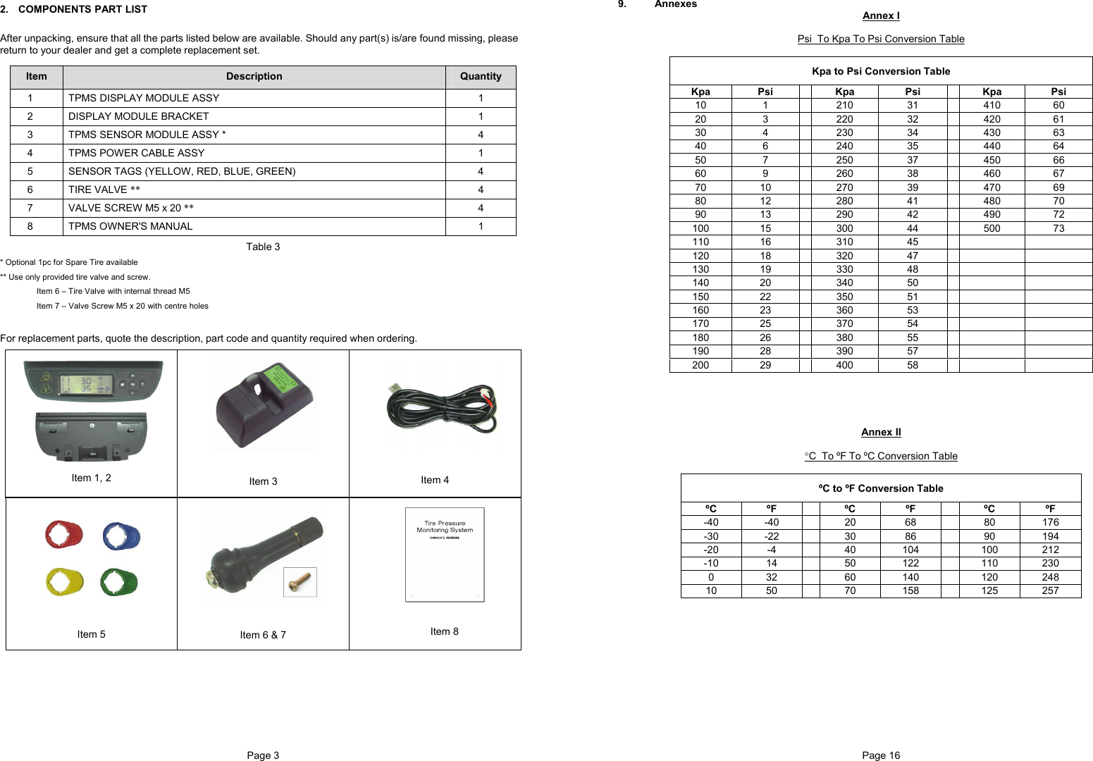
![Page 13 Sensor ID Learning Mode (S- 4) For programming of a new receiver unit with ID Learning Mode, refer to the following steps. Step 1 Press [OK] button to enter the ID learning Mode. Figure 35 Step 2 1. The front left tire icon will blink. Toggle [+] or [-] button to select the desired tire and press [OK] to accept the desired location. The corresponding tire ID number blinks (once per second) to indicate that it is ready to accept new Sensor ID input. 2. Inflate or deflate the corresponding tire by at least 28Kpa (4Psi). 3. When the new ID code is received, the tire icon will blink at a faster rate (twice per second); the ID number stops blinking and the module will beep for 5 second. 4. Press [OK] button to save the sensor ID. 5. Repeat Step 1 to 3 for other tire sensor(s) that needs to be replaced. Note ID ‘5’ will only be able to receive sensor signal if the Spare Tire setting is ON. (Refer to Spare Tire On/Off Mode (S- 6)) Figure 36 Step 3 Press [T] button to return to Programming Main menu display. Figure 37 Note 1. The receiver will not save any identical Sensor ID. 2. Value shown is for reference only. Page 6 Installing Sensor/Transmitter Module Note Ensure that each of the color tag correspond to the color label on the sensor. Refer Table 5 for the corresponding sensor tag to tire. Keep the colored sensor tag on the valve stem for installation and tire rotation. The following is suggested installation sequence: Transmitter Wheel Position Red (1) Left Front Yellow (2) Right Front Blue (3) Right Rear Green (4) Left Rear White (5) *Spare Tire Table 5 • Remove the original tire valve from tire rim. • Insert the provided tire valve into rim valve hole. (Figure 3a & Figure 3b.) • Position the Sensor/Transmitter rear to the mounted tire valve. (Figure 4), • Insert the provided screw to the Sensor as shown in figure 5 and screw the Sensor to the tire valve. (Figure 6). The tire valve will be the reference position of the sensor in order not to damage the sensor when removing tire from the wheel. Ensure that the screw is properly tightened to hold the sensor. • Attach the corresponding color tag to the valve stem and secure it with the valve cap by carefully twisting the tag onto the valve stem. See Figure 7a and Figure 7b. • Proceed to mount the tire onto the wheel. • Ensure that the tires are properly re-balanced. *Optional Part Figure 3a Figure 3b Figure 4 Figure 5 Figure 6 Figure 7a Figure 7b # = The tag (Figure.7a) has the same color and number as the same as the sensor label (Figure.7b). #](https://usermanual.wiki/Strong-Frontier-Sdn-Bhd/TE800-T.Users-Manual/User-Guide-508218-Page-5.png)
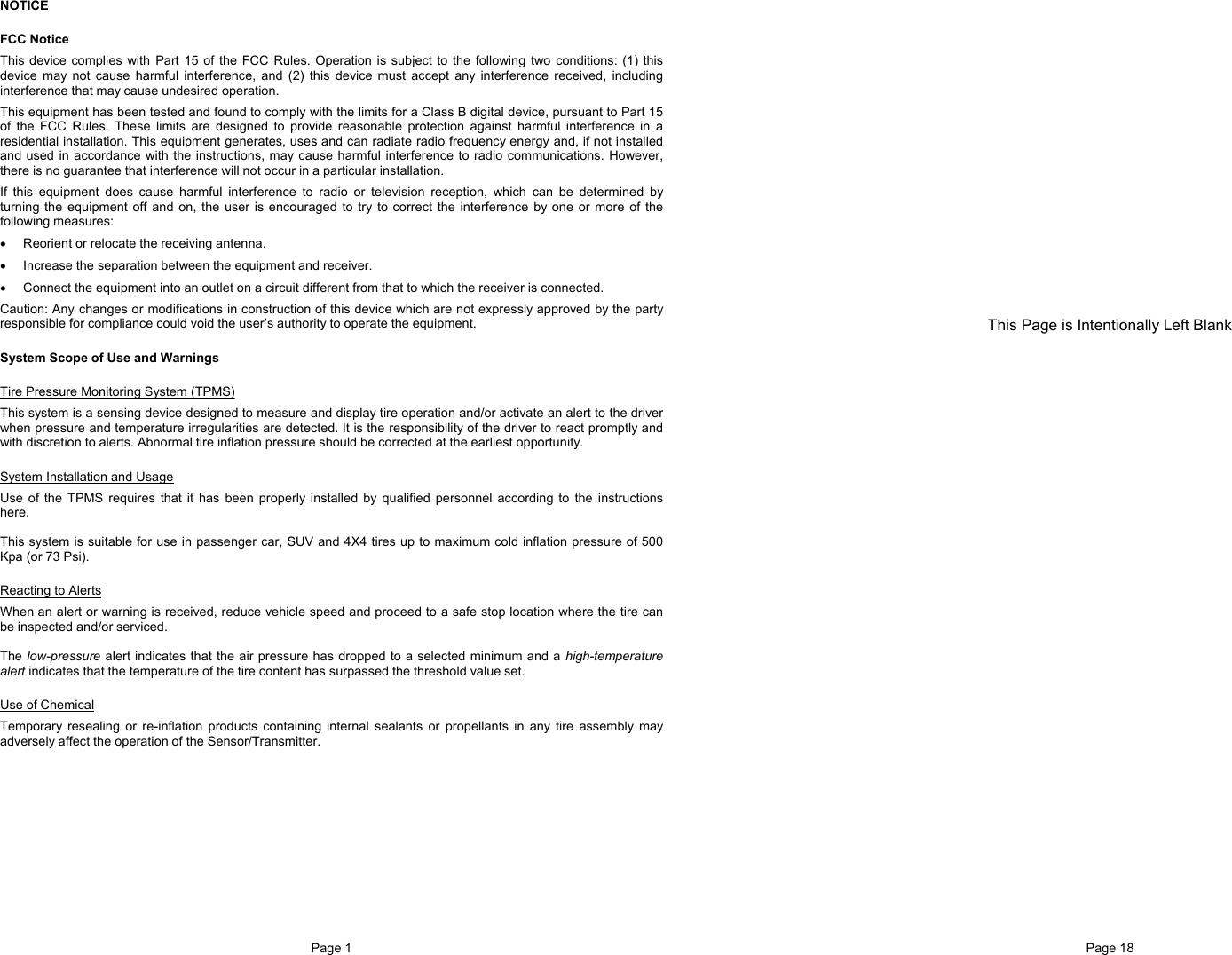
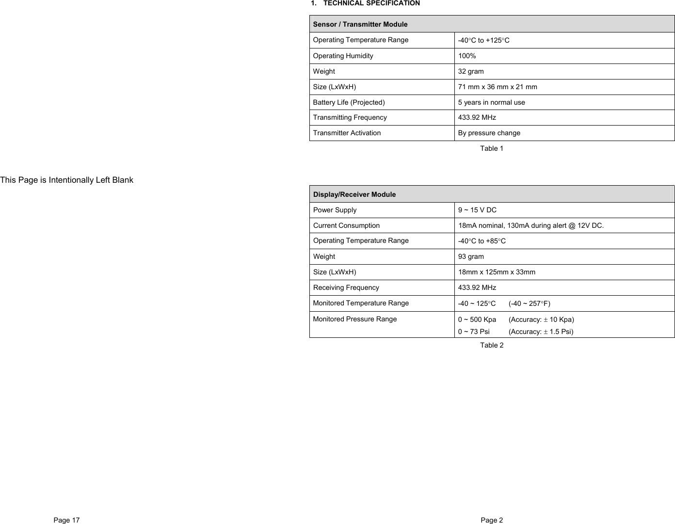
![Page 11 Programming Threshold Setting (S- 2) Press [OK] to enter the Threshold setting mode. There are two available threshold setting mode available, 1. User setting (USr) 2. Factory Default (FAC) Figure 25 Upon entering this mode, the selected threshold setting mode will blink, indicating that the currently selected mode and it is ready to accept changes of the mode. Pressing the [ + ] button or [ - ] button to toggle the mode to USr or FAC. (refer figure 26) Figure 26 Factory Default To use the factory default mode, toggle [+] or [-] button till the ‘FAC’ setting blinks. 1. Press [OK] to view the factory default for High Pressure Alert, 2. Press [OK] second time for Low pressure Alert and press [OK] the third time for Temperature threshold alert. Finally press [OK] again to accept and select the Factory default setting. Note All TPMS unit comes with a factory-preset value of 120 Kpa (23 Psi) for the Low Pressure Alert, 300 Kpa (44 Psi) for High-pressure alert and 80ºC (176ºF) for the High Temperature Alert. Figure 27 User Setting 1. To use the User setting mode, toggle [+] or [-] button till the ‘USr’ setting blinks. 2. Press [OK] to enter user setting programming mode. The 1st digit of High Pressure alert will blink. (Figure 28) 3. Toggle [+] or [-] button to make the value changes. 4. Press [OK] to confirm the changes. The next digit will blink to indicate that it is ready to accept new input. 5. Repeat steps 3 and 4 to adjust the value of other digits on the LCD display. 6. Repeat step 2 to step 5 for both Low Pressure Alert (Figure 29) and High temperature alert (Figure 30). Note For low and high pressure alert, the maximum limit is 399Kpa (58 Psi) while for temperature; the maximum limit is 99ºC (210ºF). To confirm the selected value, press the [OK] button to save it. Figure 28 Figure 29 Figure 30 Note 1. Value shown is for reference only. 2. The setting of Manual Threshold Setting can only be done in Kpa (Pressure) and ºC (Temperature). Refer to Annex 1 & 2 for conversion between the units. Page 8 Recommended Installation for Display/Receiver Module and Bracket Figure 11 1. Determine the desired location for Display/Receiver Module. Refer Figure. 12 for possible locations 2. Peel off the film covering the piece of black adhesive double-sided-tape film on the back of the display bracket. (Figure 13) 3. Mount the Display Module to the desired location. (Figure 14) 4. Apply pressure around the Display/Receiver Module for maximum mounting of the module to the car windscreen. (Figure 15) 5. If the module did not fix well to the windscreen, take out the Display module from the bracket. (Figure 16 and Figure 17) 6. Apply pressure around the bracket panel for maximum mounting of the bracket to the car windscreen. (Figure 18) 7. Install back the Display/Receiver module to the bracket. (Figure 19) Figure 12 Figure 13 Figure 14 Figure 15 Figure 16 Figure 17 Figure 18 Figure 19](https://usermanual.wiki/Strong-Frontier-Sdn-Bhd/TE800-T.Users-Manual/User-Guide-508218-Page-6.png)
![Page 9 6. PROGRAMMING Figure 20 To Enter Programming mode Main Menu 1. Ensure that the power is switched ON 2. Press and hold [M] button for 3 sec or more In programming mode toggle the [+] or [-] button for desired programming mode from S-1 to S-6. To accept the desired programming mode press [OK] button. To Quit Programming Main menu Display mode, press and hold [M] button for 3sec or more. Page 10 Display Mode (S- 1) Press [OK] to enter programming display mode. ‘ror’ or ‘noL’ will blink to indicate that it is ready to accept changes. Toggle [+] or [-] button to alternate between Rotation Mode and Normal Mode. Rotation Mode Each of the tires will be ‘scanned’ for the reading. The rotation will begin from Front Left tire, followed by Front Right Tire, Rear Right Tire, Rear Left Tire and the cycle will begin again with the Front Left Tire. This is indicated by a blinking tire icon. J K L I Figure 22 Figure 21 Rotation Mode Activated Normal Mode In the normal mode, the display will always show information of the tire with the lowest pressure value. The rotation mode tire symbol will be disabled indicating the selected mode is normal mode. (Refer to figure 23 & 24) To view information of other tires, press [T] button. Figure 24 Figure 23 Normal Mode Activated Note Value shown is for reference only.](https://usermanual.wiki/Strong-Frontier-Sdn-Bhd/TE800-T.Users-Manual/User-Guide-508218-Page-7.png)
![Page 7 5. DISPLAY/RECEIVER MODULE Figure 8 LCD Display Installation 1. Insert the Power Supply Cable connector into Receiver socket, which is located at the top rear. (Figure 9 &10). 2. Connect the other end of the Power Supply Cable to the vehicle +12VDC, Ground and ACC. Figure 9 Connection of Power Cable RED color wire to vehicle +12V DC, BLACK color wire vehicle Ground, ORANGE color Wire to vehicle ACC, Figure 10 Wiring Diagram Sensor Battery Status User setting selected. ID learning mode. Backlight selection.Temperature in °C. Temperature in °F ID exchange mode. Tire monitor mode. Pressure alert icon. Pressure in Kpa Pressure in Psi Pressure in Bar. Measured Temperature Readout Rear Right Tire Front Right Tire Measured Pressure Readout Front Left Tire Rear Left Tire Spare Tire Page 12 Sensor ID Exchange Mode (S- 3) After rotation of tires, the Sensor ID data in the receiver must be changed accordingly to ensure that it indicates the correct tire when there are any irregularities. Step 1 Press [OK] button to enter ID Exchange mode. Figure 31 Step 2 The Front left tire icon and its corresponding ID digit will blink. 1. Use [+] and [-] button to change the selected Sensor ID digit. 2. Press [OK] to confirm the changes and the next ID digit will blink accordingly. 3. Repeat step 1 and 2 for all other ID digits. 4. The ID number ‘5’ will only be available if the spare tire setting is ‘ON’ Figure 32 Step 3 Press [T] button to quit the ID Exchange mode without saving and return back to Programming Main menu display. Figure 33 Step 4 The receiver will return back to Programming Main menu display and that complete the process of exchanging Sensor ID data in the receiver. Note The receiver will not save the information if any of the tires are found to have identical Sensor ID. Figure 34 Note 1. Value shown is for reference only.](https://usermanual.wiki/Strong-Frontier-Sdn-Bhd/TE800-T.Users-Manual/User-Guide-508218-Page-8.png)
![Page 5 4. SENSOR/TRANSMITTER MODULE Installation Caution: Qualified personnel must perform the following installation procedures to ensure that the Sensor/Transmitter Module are properly installed and undamaged. It does not include any standard procedures normally required in the process of replacing a tire but due care should be taken to ensure that the sensors are not damaged. Tools Required • Tire changing equipment • Tire balancing equipment • Philip Screwdriver Figure 2 Sensor Module Figure 2a – How to Install Sensor Module with Tire ValvePage 14 Turn Backlight On/Off (S- 5) For programming backlight setting, refer to the following steps. 1. Backlight On (Permanent On) 2. Backlight Off (Auto) Step 1 Press [OK] button to enter Backlight programming mode. Figure 38 Step 2 The default-selected option will blink. 1. To change the selection On-Off press [+] or [-] button. 2. To confirm the selection press [OK] button. 3. The receiver will return back to Programming Main menu display Figure 39 Activate Spare Tire On/Off Mode (S- 6) For programming Spare Tire setting option, refer to the following steps. 1. Spare Tire On (Enable Spare Tire monitoring) 2. Spare Tire Off (Disable Spare Tire monitoring) Step 1 Press [OK] button to enter the Spare Tire setting Mode. Figure 40 Step 2 The default-selected option will blink. 4. To change the selection On-Off press [+] or [-] button. 5. To confirm the selection press [OK] button. 6. The receiver will return back to Programming Main menu display Figure 41](https://usermanual.wiki/Strong-Frontier-Sdn-Bhd/TE800-T.Users-Manual/User-Guide-508218-Page-9.png)