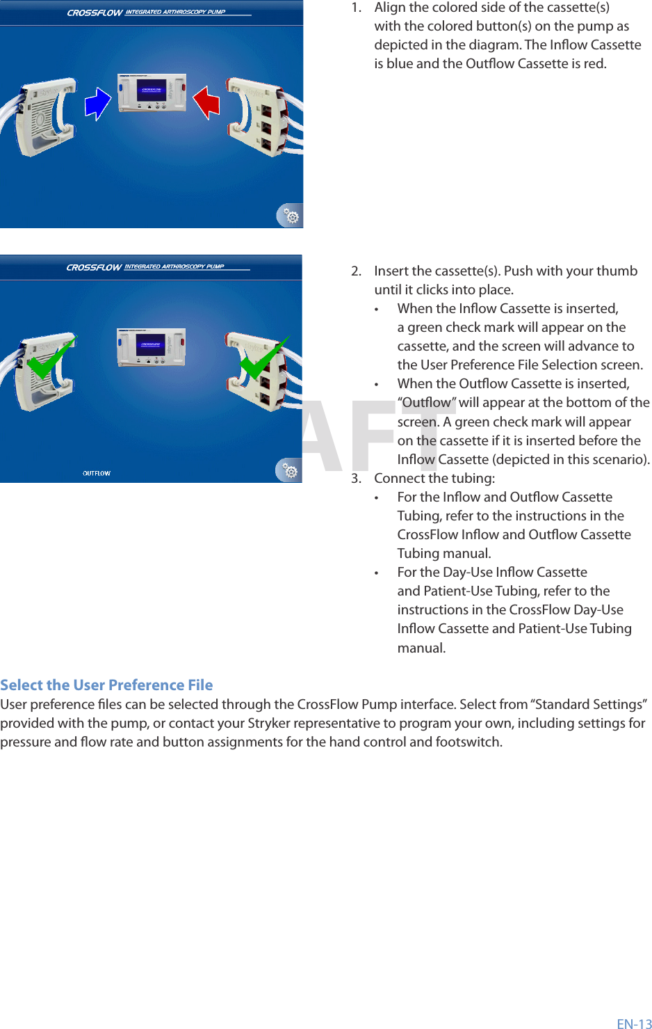
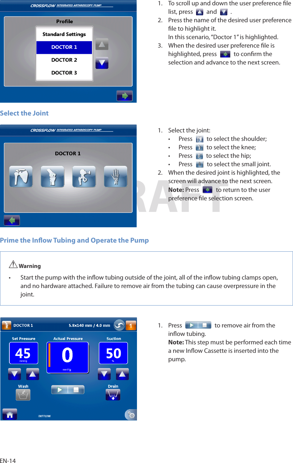
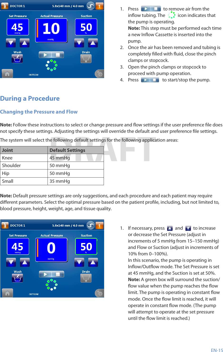
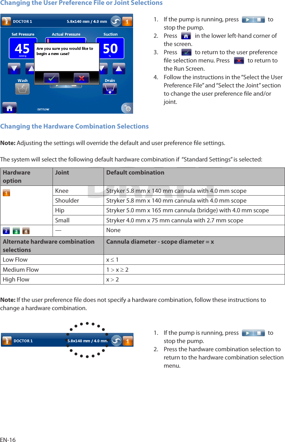
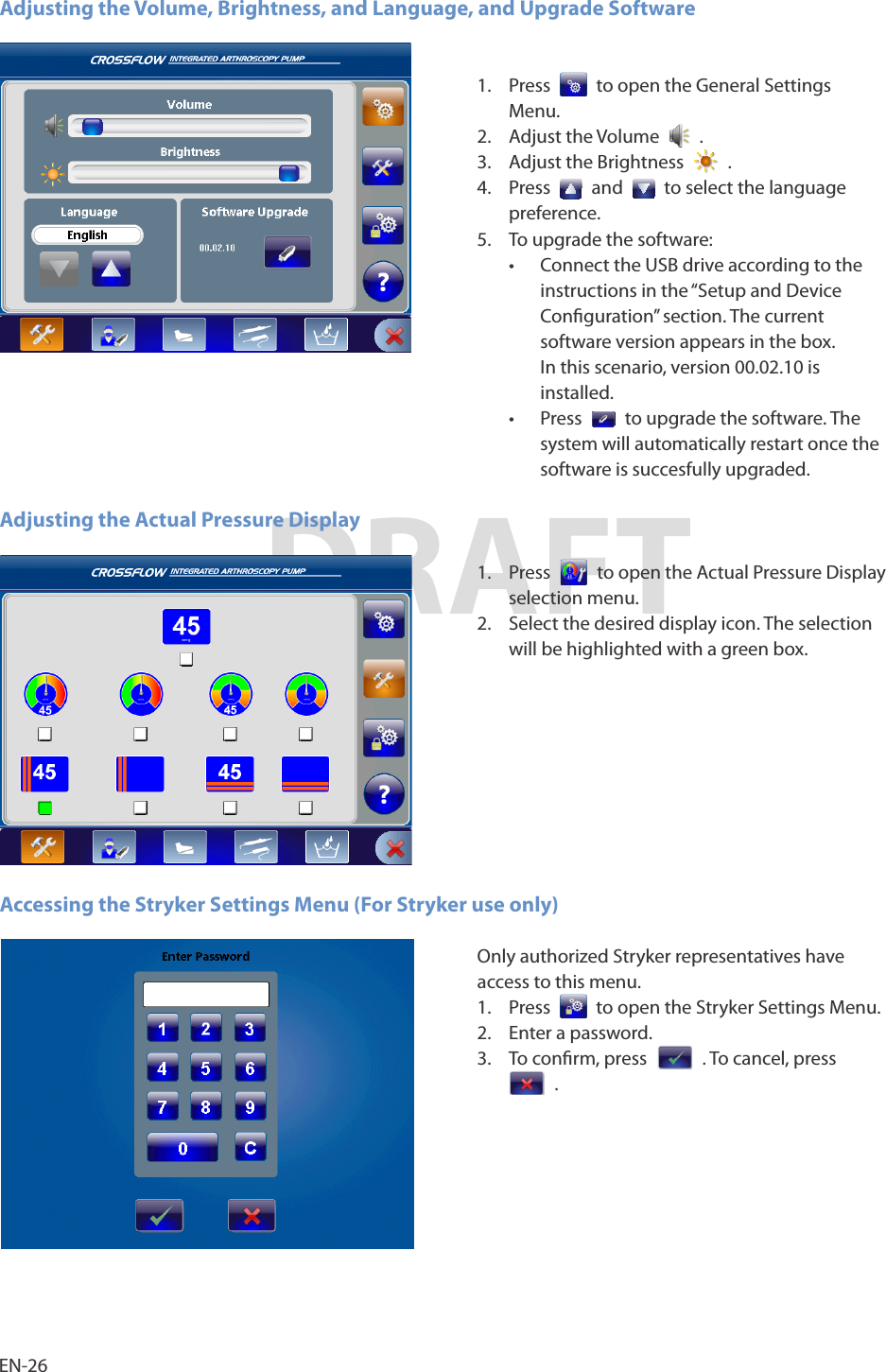
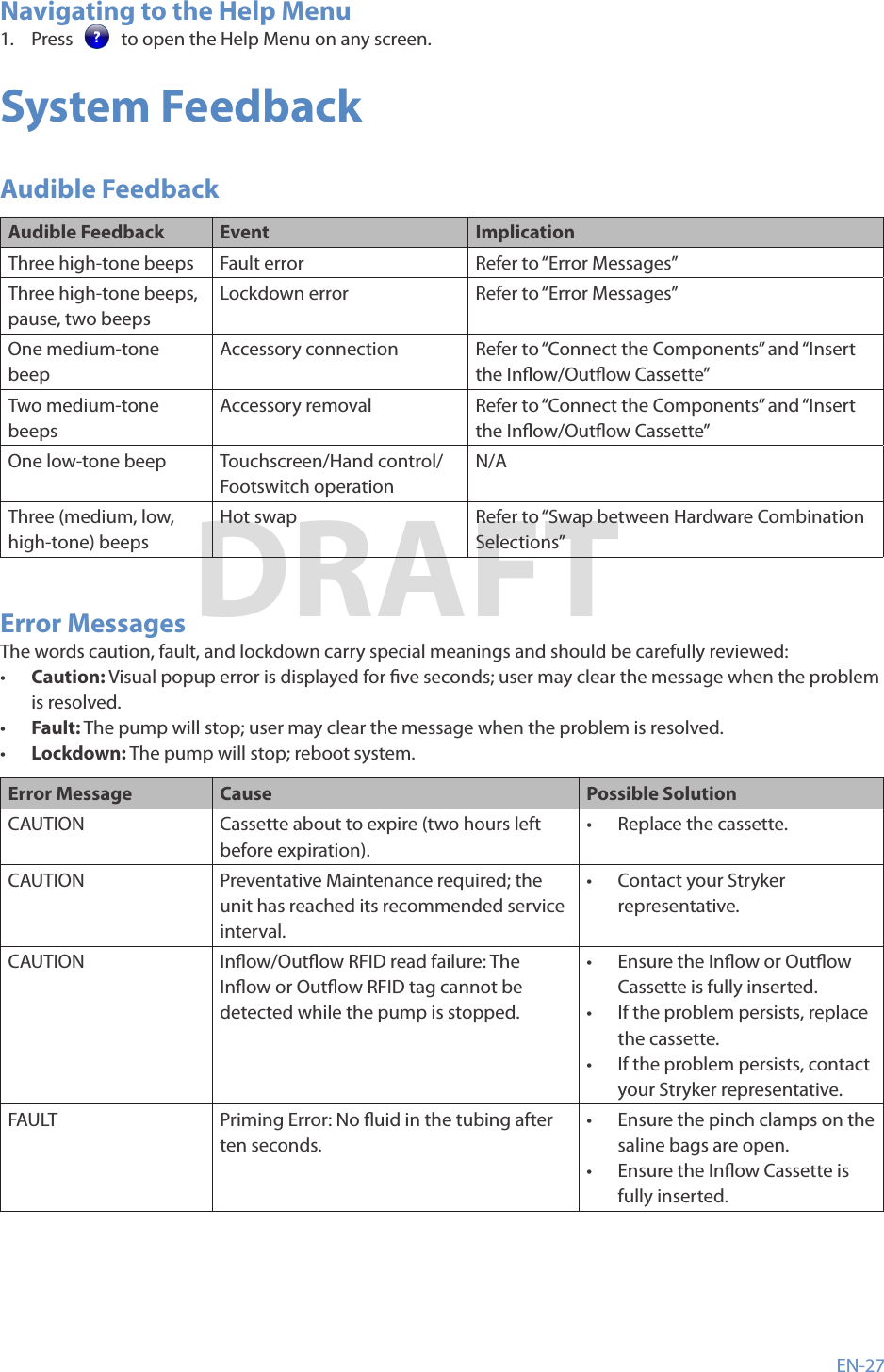
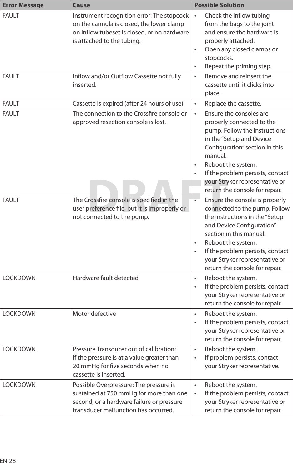
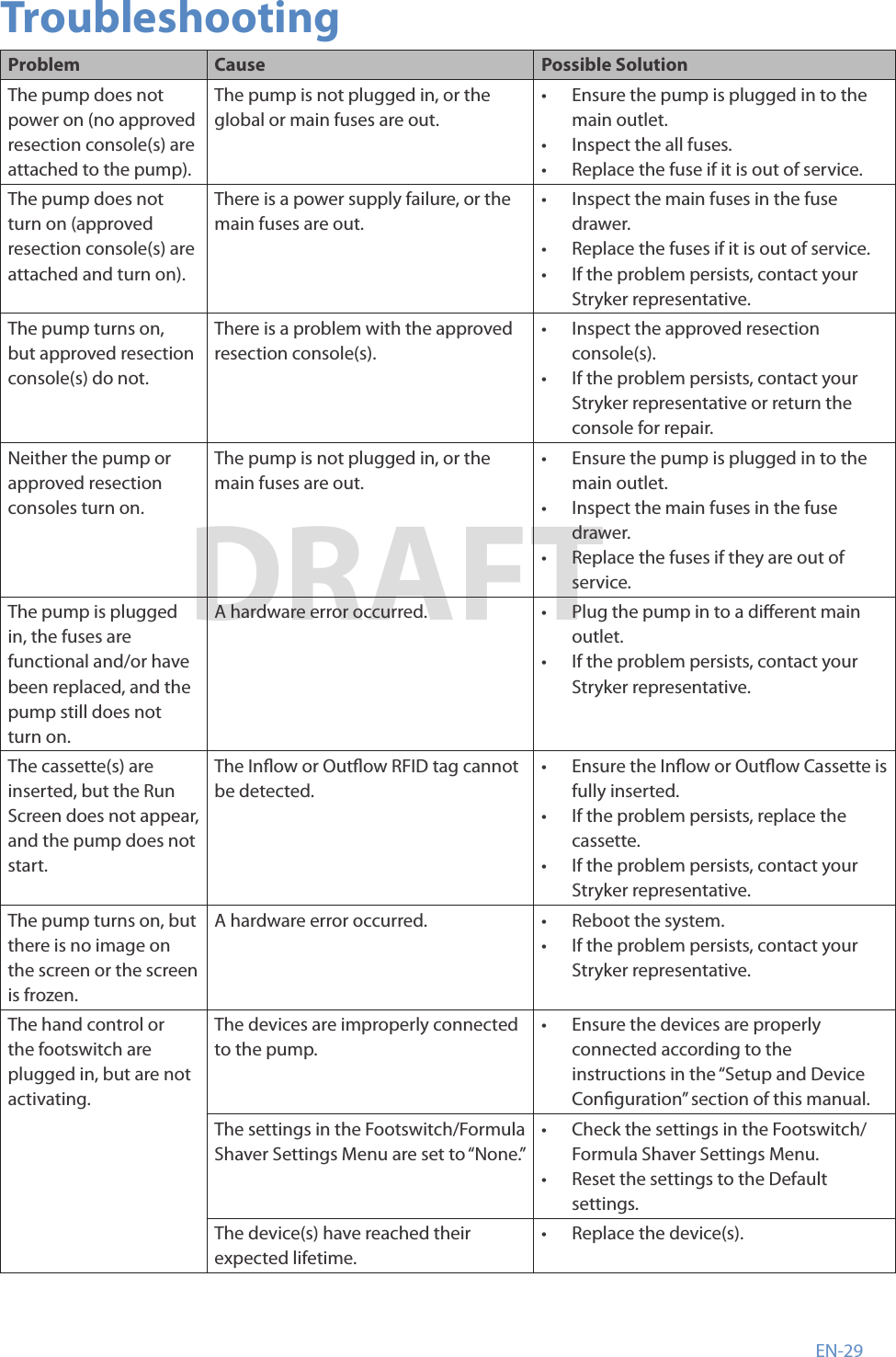
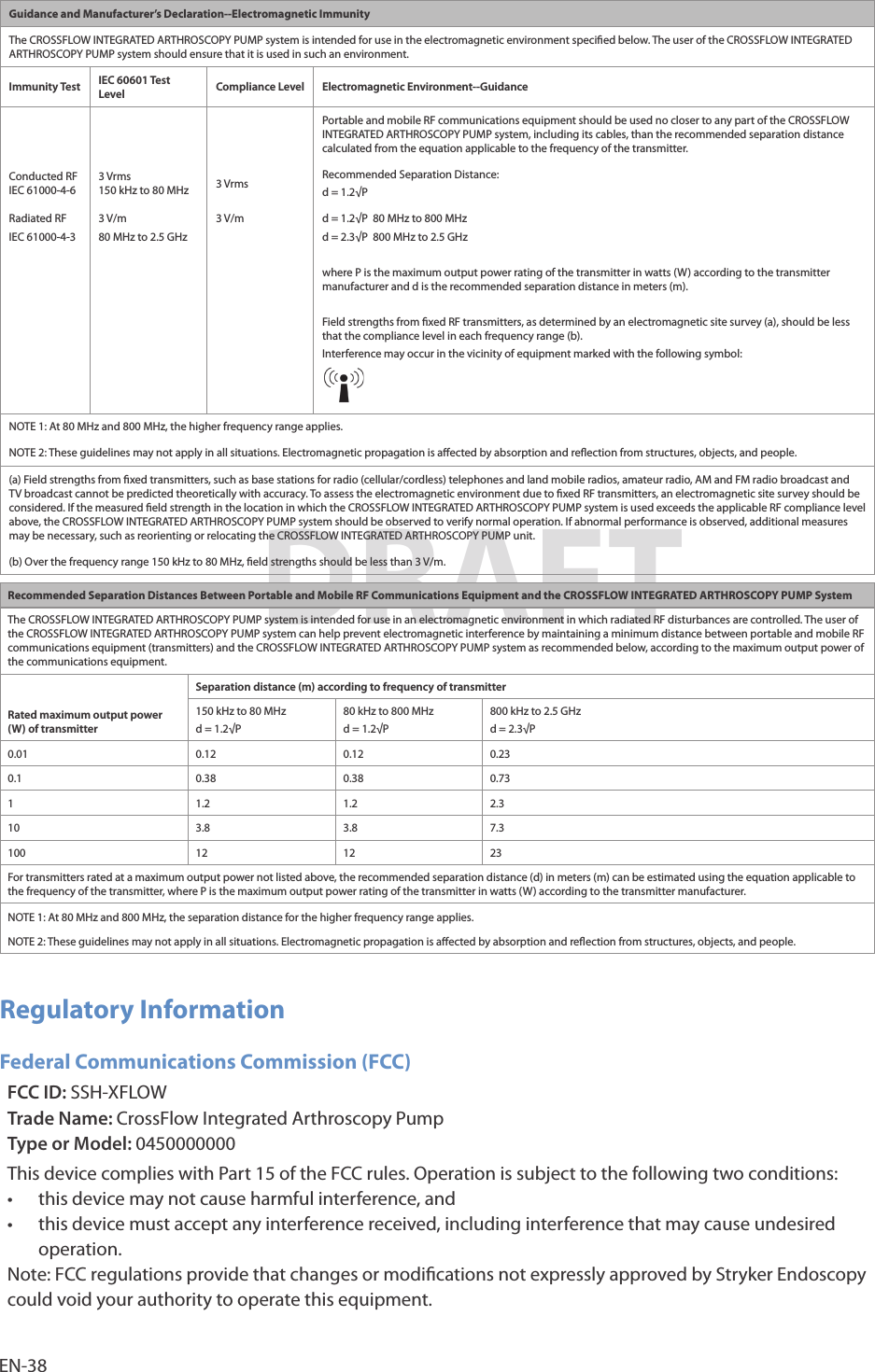
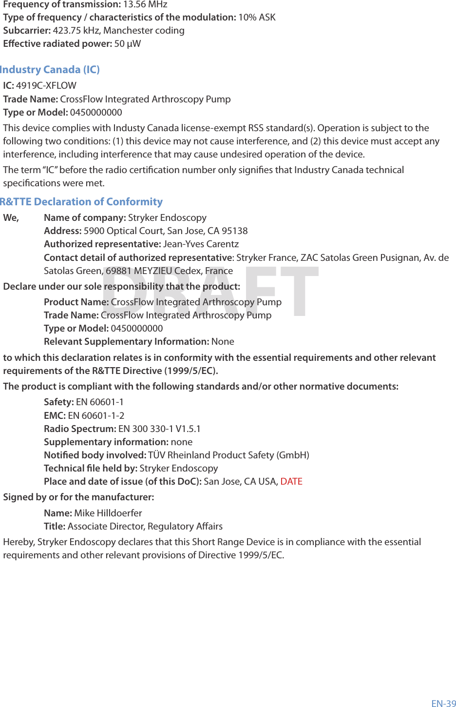
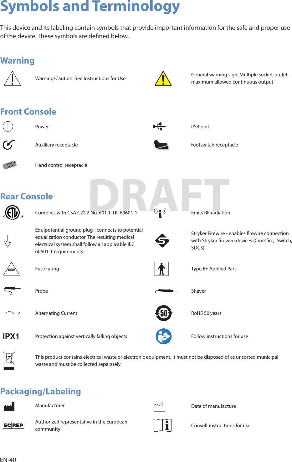
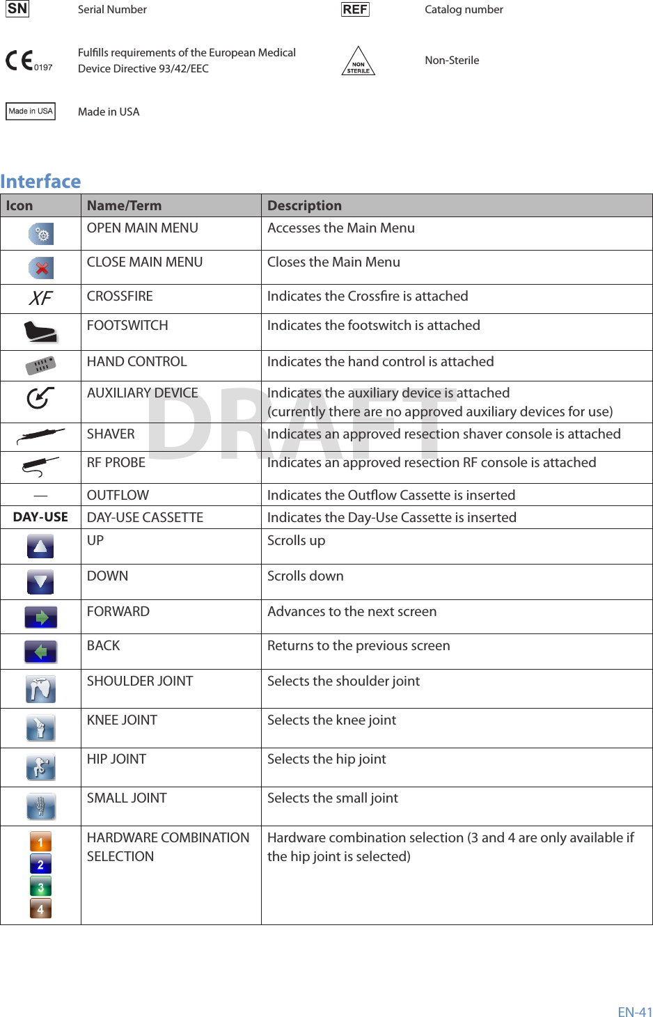
Stryker Endoscopy XFLOW Integrated Arthroscopy Pump User Manual

Stryker Endoscopy Integrated Arthroscopy Pump Users Manual

Users Manual

DRAFT  0450000000CrossFlow™ Integrated Arthroscopy PumpDRAFT
DRAFT
EN-1DRAFTTable of ContentsWarnings ........................................................................................................................................... 3Operator Prole �������������������������������������������������������������������������������������������������������������������������������������������� 3Prior to Surgery ���������������������������������������������������������������������������������������������������������������������������������������������3During Surgery ��������������������������������������������������������������������������������������������������������������������������������������������� 4After Surgery �������������������������������������������������������������������������������������������������������������������������������������������������� 4Cautions ............................................................................................................................................5About Your Product .........................................................................................................................6Product Description/Intended Use ��������������������������������������������������������������������������������������������������������6Indications ������������������������������������������������������������������������������������������������������������������������������������������������������ 7Contraindications ����������������������������������������������������������������������������������������������������������������������������������������� 7Package Contents ���������������������������������������������������������������������������������������������������������������������������������������� 7Part Numbers and Available Accessories* ������������������������������������������������������������������������������������������ 7Approved Resection Consoles ���������������������������������������������������������������������������������������������������������������� 7Front Panel ������������������������������������������������������������������������������������������������������������������������������������������������������ 8Rear Panel ������������������������������������������������������������������������������������������������������������������������������������������������������� 8Setup and Device Conguration ..................................................................................................9Operation ........................................................................................................................................12Starting a Procedure ���������������������������������������������������������������������������������������������������������������������������������12During a Procedure �����������������������������������������������������������������������������������������������������������������������������������15After a Procedure ���������������������������������������������������������������������������������������������������������������������������������������18Menu Features ...............................................................................................................................20Opening and Closing the Main Menu ������������������������������������������������������������������������������������������������20Programming the Wash and Clear Functions Settings  ���������������������������������������������������������������������������������20Programming the Resection Integration Settings �������������������������������������������������������������������������21Programming the Footswitch and Formula Shaver Settings �����������������������������������������������������22Loading User Preference Files����������������������������������������������������������������������������������������������������������������24Navigating to the Settings Menu ���������������������������������������������������������������������������������������������������������25Navigating to the Help Menu ����������������������������������������������������������������������������������������������������������������27System Feedback ...........................................................................................................................27Audible Feedback ��������������������������������������������������������������������������������������������������������������������������������������27Error Messages ��������������������������������������������������������������������������������������������������������������������������������������������27Troubleshooting ............................................................................................................................29Cleaning, Maintenance, and Disposal .......................................................................................32Clean the Components ����������������������������������������������������������������������������������������������������������������������������32Replace the Fuses ���������������������������������������������������������������������������������������������������������������������������������������32Perform Annual Inspection ��������������������������������������������������������������������������������������������������������������������33Perform Preventive Maintenance and Calibration �������������������������������������������������������������������������35Expected Life �����������������������������������������������������������������������������������������������������������������������������������������������35Disposal ���������������������������������������������������������������������������������������������������������������������������������������������������������35Technical Specications ...............................................................................................................36Equipment Information ���������������������������������������������������������������������������������������������������������������������������36
EN-2DRAFTElectromagnetic Compatibility �������������������������������������������������������������������������������������������������������������37Regulatory Information ���������������������������������������������������������������������������������������������������������������������������38Symbols and Terminology ...........................................................................................................40
EN-3DRAFTPlease read this manual and follow its instructions carefully� The words warning, caution, and note carry special meanings and should be carefully reviewed:•  Warning: Indicates risks to the safety of the patient or user� Failure to follow warnings may result in injury to the patient or user�•  Caution: Indicates risks to the equipment� Failure to follow cautions may result in product damage� •  Note: Provides special information to clarify instructions or present additional useful information�WarningsOperator Prole1�  Federal (USA) law restricts this device to sale by or on the order of a physician�2�  The operator of the CrossFlow™ system should be a qualied health care professional having complete knowledge of the use of this equipment and awareness of the risks associated with arthroscopic procedures�3�  The operator of the system should be experienced in arthroscopic practices and techniques�4�  The operator of the system should read this manual thoroughly and be familiar with its contents prior to operating the equipment�Prior to Surgery1�  Carefully unpack the CrossFlow Integrated Arthroscopy Pump and ensure that all components listed in the “Package Contents” section of this manual are accounted for and remain undamaged from shipment� If damage to any component is detected, refer to the standard warranty�2�  Install the system in an operating room that complies with all applicable IEC, CEC, and NEC requirements for safety of electrical devices�3�  Install and use the system according to the information provided in the “Electromagnetic Compatibility” section of this manual� 4�  If the pump is installed with other equipment in a stacked conguration, observe the pump to verify normal operation�5�  Portable and mobile RF communications equipment may interrupt system operation� When the pump is in use, the conducted and radiated electrical elds may interfere with other electrical medical equipment� If this occurs, power down all electrical equipment not in use, increase distance of other electrical equipment, and/or connect the pump and other equipment into dierent outlets�6�  Place the pump at the same height as the joint to ensure accurate pressure readings. 7�  Ensure the proper connection of the primary power cord of the pump to a grounded receptacle with the correct mains voltage� To prevent the risk of electric shock, do not use extension cords or portable multiple socket outlets that are not a part of a certied hospital cart� The use of a portable multiple socket outlet can lead to a reduced level of safety�8�  Position any cables extending from the pump to avoid contact with the patient, electrodes, other cables, and any electrical leads which provide paths for high frequency current�9�  Do not connect items which are not specied as part of the system� The use of accessories, transducers, and cables other than those specied in this manual may result in increased emissions, decreased immunity of the equipment, or unintended, unsafe operation of the system�10�  Examine all electrical connections to the pump before use� Improper connection may result in malfunction or unintended surgical eects�11�  Do not touch or insert any objects, other than the cassettes, inside of the cassette holders as this may
EN-4DRAFTdamage the pressure sensor or cause injury� Place only the cassettes in the cassette holders� 12�  Set the alarm volume to a level that is audible in the operating room environment� 13�  Ensure the system functions as outlined in this manual prior to a surgical procedure� The system was fully tested at the factory before shipment�During Surgery 1�  Using uid to distend the joint carries the possibility of uid extravasation into surrounding tissue� Select the optimal pressure based on the patient prole, including, but not limited to, blood pressure, height, weight, age, and tissue quality� Recommended pressure settings are included in this manual; however, these are only suggestions, and each surgery and each patient may require dierent parameters� 2�  The Wash function may cause high pressure within the joint, which may lead to uid extravasation� Carefully monitor joint pressure when using this function� 3�  The Clear function may cause excessive uid usage� Monitor the use of this function and the uid level in the irrigation bags�4�  Use the scope and cannula as selected on the pump� Incorrect scope and cannula use can cause overpressure if it does not match the selected scope and cannula� 5�  Start the pump with the inow tubing outside of the joint, all of the inow tubing clamps open, and no hardware attached� Failure to remove air from the tubing can cause overpressure in the joint�  6�  The pump is only intended for use with exible uid containers� Do not use glass containers as they might implode due to the vacuum being generated inside of the container� 7�  Do not use this system in the presence of oxidizing agents or ammable materials (e�g� anaesthetics, gases, uids, skin prepping agents, and tinctures)� Observe appropriate re precautions at all times�8�  Keep the pump dry� If liquid has accidentally leaked into the pump from the cassette(s), change the cassette(s), restart the system, and verify operation�9�  Keep the LCD screen and speaker in the eld of view and hearing at all times during use� These are important safety features�10�  Failure of the system may result in an unintended increase or decrease in ow and/or pressure� Carefully the monitor the joint when using the system�11�  Do not allow extended exposure of suction to tissue associated with procedures that require either no or low-ow suction� Always consider the type of tissue associated with the surgical procedure before using this system� Failure to comply may result in severe injury�After Surgery1�  Do not remove the cover of the console as this could cause electric shock and product damage.2�  Disconnect the pump from the electrical output when cleaning, servicing, or inspecting fuses�3�  Do not make any internal repairs or adjustments� Units requiring repair should be returned to Stryker� Decontaminate the pump and accessories prior to returning them to Stryker� Stryker may refuse to carry out repairs if the products are contaminated�4�  Do not use ammable agents for cleaning and disinfecting the system�5�  Do not sterilize the pump�6�  Follow the instructions in the “Disposal” section of this manual to adequately dispose of system accessories�
EN-5DRAFTCautions1�  No modication of this equipment is allowed� 2�  Insert the cassette prior to spiking the saline bag� Failure to do so may damage the pump or the cassette� 3�  Do not remove the cassettes while the pump is in use� The pump or the cassette may be damaged� The cassettes can only be removed when the pump is stopped� 4�  Stryker does not accept any liability for direct or consequential damages if:•  the pump or the accessories are used improperly,•  the instructions and rules in the manual are not followed,•  the pump or the accessories are improperly connected and maintained,•  non-authorized persons perform repairs, adjustments, or alterations to the pump or accessories,•  non-authorized persons open the pump,•  the prescribed inspection and maintenance schedules are not followed�The warranty is void if any of these warnings or cautions is disregarded�
EN-6DRAFTAbout Your ProductProduct Description/Intended UseThe Stryker CrossFlow Integrated Arthroscopy Pump is a uid management system� Illustrated below, the system is composed of a pump console with inow-only and inow/outow modes, disposable cassette tubing, a wired hand control, and a wired footswitch� The system integrates with approved resection consoles�1�  CrossFlow Integrated Arthroscopy Pump (featured in this manual) - Compatible with the Crossre Console, CrossFlow Footswitch, Autoclavable Hand Control, iSwitch Wireless Universal Foot Control, Stryker rewire-compatible devices, and approved resection consoles�2�  CrossFlow Cassette Tubing - Compatible with the CrossFlow Integrated Arthroscopy Pump, 4-bag adapter with inow cassettes, luer-lock connectors, standard irrigation uids, suction connectors, and waste management systems� The user may elect to employ one of two modes of operation: •  Inow-Only Mode: utilizes only the inow function of the pump via the Inow Cassette Tubing or the Day-Use Inow Cassette/Patient-Use Tubing•  Inow Cassette Tubing - The Inow Cassette Tubing transmits uid from saline bags to the inow cannula at the surgical site and is disposed of after each case�•  Day-Use Inow Cassette/Patient-Use Tubing - The Day-Use Inow Cassette Tubing is used for a single day’s cases, and the Patient-Use Tubing is connected to the Day-Use Inow Cassette Tubing for a single case, then removed and discarded�•  Inow/Outow Mode: utilizes both the inow and outow functions of the pump via the Inow Cassette Tubing and Outow Cassette Tubing�3�  CrossFlow Footswitch (optional) - Provides remote foot control of pump operation�4�  Autoclavable Hand Control (optional) - Provides remote hand control of pump operation�
EN-7DRAFTIndicationsThe CrossFlow Integrated Arthroscopy Pump is a dual arthroscopic pump system intended to provide uid distension and irrigation of the knee, shoulder, hip, elbow, and ankle and wrist joint cavities and uid suction during diagnostic and operative arthroscopic procedures�ContraindicationsThe use of the CrossFlow Integrated Arthroscopy Pump is prohibited whenever arthroscopy is contraindicated�Package ContentsCarefully unpack the CrossFlow Integrated Arthroscopy Pump and ensure all components are accounted for and remain undamaged from shipment� If damage to any component is detected, refer to the standard warranty�•  (1) CrossFlow pump•  (1) Hospital power cord•  (2) Approved resection console power cord•  (1) User manual•  (1) Warranty and return policyPart Numbers and Available Accessories*The CrossFlow Integrated Arthroscopy Pump is featured in this manual� Refer to individual manuals for all other products and accessories�Part Number Description0350220000 Autoclavable Hand Control*0450000000 CrossFlow Integrated Arthroscopy Pump 0450000100 CrossFlow Inow Cassette Tubing0450000110 CrossFlow Day-Use Inow Cassette Tubing0450000120 CrossFlow Patient-Use Tubing0450000200 CrossFlow Outow Tubing0450000300 CrossFlow Integrated Cassette Tubing0450000500 CrossFlow Footswitch*Approved Resection ConsolesThe CrossFlow system is compatible with the following consoles� (Contact Stryker Endoscopy for compatibility requirements for any non-approved resection consoles�) •  Arthrex APS II •  Dyonics Power •  Stryker CORE•  Arthrex OPES •  Dyonics Power II •  Stryker SERFAS•  Arthrocare ATLAS •  Linvatec Advantage •  Stryker TPS•  Arthrocare Quantum •  Mitek VAPR•  Arthocare Quantum II •  Smith and Nephew Vulcan
EN-8DRAFTFront Panel1�  LCD Touchscreen 2�  Outow Cassette Ejection Button3�  Outow Cassette Holder 4�  Hand Control Receptacle5�  Footswitch Receptacle 6�  Auxiliary Receptacle7�  USB Port 8�  Power Button9�  Inow Cassette Holder 10�  Inow Cassette Ejection ButtonRear PanelT10A 250V T3A 250VFCC ID: SSH-XFLOW This device complies with part 15 of the FCC Rules. Operation is subject to the following two conditions: (1) This device may not cause harmful interference, and (2) this device must accept any interference received, including interference that may cause undesired operation.IC: 4919C-XFLOW1�  Speaker 2�  Power Outlet for Approved Resection RF Console 3�  Power Outlet for Approved Resection Shaver Console4�  AC Power Inlet5�  Fuse Drawer 6�  Global Fuse Holders7�  Equipotentiality Ground Plug 8�  SFB Connector Ports
EN-9DRAFTSetup and Device CongurationStryker Endoscopy considers instructional training an integral part of the CrossFlow system� Your Stryker Endoscopy representative will perform at least one in-service at your convenience to help you set up your equipment and instruct you and your sta on its operation and maintenance� Please contact your local Stryker Endoscopy representative to schedule an in-service after your equipment has arrived�1�  Choose a location for the CrossFlow pump�•  Place the pump on a Stryker cart or other sturdy platform near a hospital grade outlet�•  Place the pump at the same height as the joint to ensure accurate pressure readings.•  Provide at least four to six inches of space around the sides of the pump to ensure proper ventilation and allow access to the power cord� WarningRF and other mobile communications equipment may aect the normal function of the CrossFlow pump� When placing the pump, follow the instructions located in the “Electromagnetic Compatibililty” section of this manual�2�  Connect the AC power�•  Connect the provided hospital power cord to the AC inlet on the rear console panel�•  Connect the other end to a hospital-grade power outlet� Warning•  Check the device label on the rear of the pump to determine the operating voltage of the device�•  Check the power cord assembly periodically for damaged insulation or connectors�•  To avoid risk of electric shock, this equipment must only be connected to a supply mains with protective earth�Caution•  When connecting or disconnecting a cable, hold the cable by its connector (its plug, not the cord)� Failure to comply may result in damage to the cable or pump�•  Connect the power cords directly to the AC inlet or outlet� Do not connect any of the power cords together�If required, connect the pump to a Stryker Firewire-compatible device using one of the SFB connector
EN-10DRAFTports on each device�Note: Refer to the manual supplied with each Firewire-compatible device for connection information�3�  If required, connect the approved resection console(s) according to the interconnection diagram�•  Using a #1 Phillips screwdriver, unscrew and remove the power cord bracket�•  Connect the approved resection power cord to the AC inlet on the approved resection console� Refer to the manual supplied with each approved console for connection information�•  Connect the other end to the power cord to the power outlet for the approved resection console on the rear panel of the CrossFlow pump, as marked�•  Using a #1 Phillips screwdriver, attach and secure the power cord bracket�Note: The pump’s screen will display the specic components that are connected when the device is powered on� WarningWhen the CrossFlow pump is interconnected with other electrical devices, leakage currents may be additive, resulting in electromagnetic emissions that can interfere with the normal function of electronic medical equipment� To properly control electromagnetic emissions and avoid potential harm to the patient or user, ensure all electrical devices are installed and interconnected according to the requirements of IEC 60601-1-1�CautionEnsure the approved resection consoles are connected to the correct power outlets on the rear panel of the pump�
EN-11DRAFT4�  If required, connect the hand control, footswitch, and/or USB drive according to the interconnection diagram�Note: Stryker recommends using the SIDNE USB2�0 Flash Disk, 512MB (P/N 0105-201-529)�Note: The pump’s screen will display the specic components that are connected when the device is powered on�Caution•  Do not connect an ethernet cable to the auxiliary port�•  Turn the connector of the hand control and footswitch so that the red dot points up�•  Do not thread or twist the cable connector for insertion or removal� It is a push/pull connector and may be damaged by twisting it into or out of place�5�  For tubing connection instructions, refer to the CrossFlow Inow and Outow Cassette Tubing and the CrossFlow Day-Use Inow Cassette and Patient-Use Tubing manuals�
EN-12DRAFTOperationNote: Refer to the “Symbols and Terminology” section in this manual for button and icon denitions and commonly used terms�Starting a ProcedureTo start a procedure, perform the following steps:1�  Power the Pump On and O2�  Insert the Inow/Outow Cassette3�  Select the User Preference File4�  Select the Joint5�  Prime the Inow Tubing and Operate the PumpPower the Pump On and O1�  Press    located at the bottom left corner of the front panel to power on the pump� When this button is illuminated by a green LED, the system is powered on� The pump will display a splash screen while the software is loading�2�  To power o the system, press    again�Insert the Inow/Outow Cassette WarningThe choice of irrigation uid should be determined by the physician, based on the operation method to be employed�CautionThe cassettes are color-coded� When inserting the cassettes, make sure to insert them as indicated by the color-coding�
EN-13DRAFT1�  Align the colored side of the cassette(s) with the colored button(s) on the pump as depicted in the diagram� The Inow Cassette is blue and the Outow Cassette is red�2�  Insert the cassette(s)� Push with your thumb until it clicks into place� •  When the Inow Cassette is inserted, a green check mark will appear on the cassette, and the screen will advance to the User Preference File Selection screen�•  When the Outow Cassette is inserted, “Outow” will appear at the bottom of the screen� A green check mark will appear on the cassette if it is inserted before the Inow Cassette (depicted in this scenario)�3�  Connect the tubing: •  For the Inow and Outow Cassette Tubing, refer to the instructions in the CrossFlow Inow and Outow Cassette Tubing manual� •  For the Day-Use Inow Cassette and Patient-Use Tubing, refer to the instructions in the CrossFlow Day-Use Inow Cassette and Patient-Use Tubing manual�Select the User Preference FileUser preference les can be selected through the CrossFlow Pump interface� Select from “Standard Settings” provided with the pump, or contact your Stryker representative to program your own, including settings for pressure and ow rate and button assignments for the hand control and footswitch�
EN-14DRAFT1�  To scroll up and down the user preference le list, press    and    �2�  Press the name of the desired user preference le to highlight it�  In this scenario, “Doctor 1” is highlighted�3�  When the desired user preference le is highlighted, press    to conrm the selection and advance to the next screen�Select the Joint1�  Select the joint:•  Press    to select the shoulder;•  Press    to select the knee; •  Press    to select the hip; •  Press    to select the small joint� 2�  When the desired joint is highlighted, the screen will advance to the next screen� Note: Press    to return to the user preference le selection screen�Prime the Inow Tubing and Operate the Pump Warning•  Start the pump with the inow tubing outside of the joint, all of the inow tubing clamps open, and no hardware attached� Failure to remove air from the tubing can cause overpressure in the joint� 1�  Press    to remove air from the inow tubing� Note: This step must be performed each time a new Inow Cassette is inserted into the pump�
EN-15DRAFT1�  Press    to remove air from the inow tubing� The    icon indicates that the pump is operating�   Note: This step must be performed each time a new Inow Cassette is inserted into the pump�2�  Once the air has been removed and tubing is completely lled with uid, close the pinch clamps or stopcock� 3�  Open the pinch clamps or stopcock to proceed with pump operation� 4�  Press     to start/stop the pump�During a ProcedureChanging the Pressure and FlowNote: Follow these instructions to select or change pressure and ow settings if the user preference le does not specify these settings� Adjusting the settings will override the default and user preference le settings� The system will select the following default settings for the following application areas:Joint Default SettingsKnee 45mmHgShoulder 50mmHgHip 50mmHgSmall 35mmHgNote: Default pressure settings are only suggestions, and each procedure and each patient may require dierent parameters� Select the optimal pressure based on the patient prole, including, but not limited to, blood pressure, height, weight, age, and tissue quality�1�  If necessary, press    and    to increase or decrease the Set Pressure (adjust in increments of 5mmHg from 15–150mmHg) and Flow or Suction (adjust in increments of 10% from 0–100%)�  In this scenario, the pump is operating in Inow/Outow mode� The Set Pressure is set at 45mmHg, and the Suction is set at 50%�Note: A green box will surround the suction/ow value when the pump reaches the ow limit� The pump is operating in constant ow mode� Once the ow limit is reached, it will operate in constant ow mode� (The pump will attempt to operate at the set pressure until the ow limit is reached�)
EN-16DRAFTChanging the User Preference File or Joint Selections1�  If the pump is running, press    to stop the pump�2�  Press    in the lower left-hand corner of the screen�3�  Press    to return to the user preference le selection menu� Press    to return to the Run Screen�4�  Follow the instructions in the “Select the User Preference File” and “Select the Joint” section to change the user preference le and/or joint�Changing the Hardware Combination SelectionsNote: Adjusting the settings will override the default and user preference le settings�The system will select the following default hardware combination if  “Standard Settings” is selected: Hardware optionJoint Default combinationKnee Stryker 5�8mmx140mm cannula with 4�0mm scopeShoulder Stryker 5�8mmx140mm cannula with 4�0mm scopeHip Stryker 5�0mmx165mm cannula (bridge) with 4�0mm scopeSmall Stryker 4�0mmx75mm cannula with 2�7mm scope      — NoneAlternate hardware combination selectionsCannula diameter-scope diameter = xLow Flow x ≤ 1Medium Flow 1 > x ≥ 2High Flow x > 2Note: If the user preference le does not specify a hardware combination, follow these instructions to change a hardware combination�1�  If the pump is running, press    to stop the pump�2�  Press the hardware combination selection to return to the hardware combination selection menu�
EN-17DRAFT3�  Select the scope/cannula combination for option    ; to scroll up and down the hardware combination list, press    and  �4�  Press the desired hardware combination to highlight it�  In this scenario, “5�8mmx140mm cannula with 4�0mm scope” is highlighted� (Select Low, Medium, or High Flow if the desired hardware combination does not appear on the list�)5�  If no other hardware combination options are required, proceed to step 6�6�  If necessary, press    ,     , and/or  to view the available scope/cannula combinations for these options�Note: Hardware    and    are only enabled if the hip joint is selected�7�  Repeat steps 3 and 4 to select the scope/cannula combination for options    ,     , and/or    � In this scenario, “4�0x120mm cannula with 2�7mm scope” is highlighted for option    �8�  When the desired hardware combinations are highlighted, press    to conrm the selections and advance to the Run screen�Swapping Between Hardware Combination Selections During the CaseThe “Hot Swap” function allows the user to switch the cannula through which the inow tubing is attached without requiring recalibration� Depending on the surgical site, up to four cannulas can be utilized by this function� WarningUse the scope and cannula as selected on the pump� An incorrect scope and cannula selection may cause overpressure in the joint�
EN-18DRAFT1�  Press    to change to option    � A green box will briey appear displaying the new hardware combination selection�2�  Ensure the correct hardware combination is displayed� If the incorrect hardware combination selection is displayed, or to change the hardware combination selection, follow the instructions in the “Change Hardware Combination Selections” section� 3�  Press    to change to hardware combination    �Performing the Wash FunctionThe Wash function increases the set pressure and ow limit by a user-specied percentage over a user-specied duration (for Inow-only mode), or increases set pressure and suction by a user-specied percentage over a user-specied duration (for Inow/Outow mode)�1�  While the pump is running, press    to perform the Wash function� Follow the instructions in the “Program the Wash and Clear Function Settings” section to adjust the default settings�2�  Press    to repeat or stop the Wash function�Performing the Drain FunctionThe Drain function is only available in the Inow/Outow mode� It operates the outow pump to remove uid from the surgical site for 30 seconds or until the user stops the pump�1�  Press    to stop the pump� 2�  Press    to remove uid from the joint�3�  Press    to repeat or stop the Drain function�After a ProcedureRemove the CassettesCaution•  Do not remove the cassettes while the pump is in use� The pump or the cassette may be damaged� The cassettes can only be removed when the pump is stopped�•  Do not attempt to remove the Outow Cassette if it gets stuck as it may damage the pump or the cassette� Follow the instructions in the “Troubleshooting” section in this manual to resolve this problem� 1�  Press    to stop the pump�2�  Close all pinch clamps�
EN-19DRAFT3�  Refer to the CrossFlow Day-Use Inow Cassette and Patient-Use Tubing and the CrossFlow Inow and Outow Cassette Tubing manual on instructions on how to disconnect and discard the tubing� Always maintain a sterile technique� 4�  Press the Inow Cassette Ejection button (blue) and/or the Outow Cassette Ejection button (red) on the front panel of the pump to eject the cassette(s)�5�  Discard the cassettes and tubing appropriately�
EN-20DRAFTMenu FeaturesOpening and Closing the Main Menu1�  If the pump is running, press    to stop the pump�2�  Press    to open the Main Menu�3�  Press    to close the Main Menu�Programming the Wash and Clear Functions Settings Note: Adjusting the settings will override the default and user preference le settings� 1�  Press    to open the Main Menu�2�  Press    to open the Wash and Clear Settings Menu�Setting FunctionWash •  Inow-only mode: Increases set pressure and ow limit by user-specied percentage over user-specied duration� By default, the set pressure will increase by 50% of the current setting, and the ow limit will increase by 100% of the current setting for 30 seconds�•  Inow/Outow mode: Increases set pressure and suction by user-specied percentage over user-specied duration� By default, the set pressure will increase by 50% of the current setting, and the suction will increase by 100% of the current setting for 30 seconds�Clear •  Inow-only mode: Increases ow limit by user-specied percentage over user-specied duration� By default, the ow limit will increase by 100% of the current setting for 30 seconds�•  Inow/Outow mode: Increases suction rate by user-specied percentage over user-specied duration� By default, the outow will increaseby 100% of the current setting for 30 seconds�
EN-21DRAFTWash Function Settings1�  Press    to program the settings for the Wash function�2�  Press    and    to adjust the Pressure, Flow, or Duration� In this scenario, the pressure will increase by 50% and the ow will increase by 100% for 30 seconds� Clear Function Settings1�  Press    to program the settings for the Clear function�2�  Press    and    to adjust the Flow or Duration�  In this scenario, the ow will increase by 100% for 30 seconds�Programming the Resection Integration SettingsNote: Adjusting the settings will override the default and user preference le settings� 1�  Press    to open the Main Menu�2�  Press    to open the Resection Integration Settings Menu�
EN-22DRAFTShaver Console Settings1�  Press    to specify the shaver console:•  Press    to select the CrossFire console;•  Press    to select an approved resection console; •  Press    if no shaver console is in use� In this scenario, the CrossFire console is selected�2�  Press    and    to increase or decrease the Suction (adjust in increments of 10% from 0–100%)�  In this scenario, the Suction is set at 50%�RF Console Settings1�  Press    to specify the RF console:•  Press    to select the CrossFire console;•  Press    to select an approved resection console  (Press “Suction” if the RF probe is a suction probe�);•  Press    if no RF console is in use� In this scenario, an approved resection console with a suction probe is selected�2�  Press    and    to increase or decrease the Suction (adjust in increments of 10% from 0–100%)�  In this scenario, the Suction is set at 50%�Programming the Footswitch and Formula Shaver Settings1�  Press    to open the Main Menu�2�  Press    to open the Footswitch/Formula Shaver Settings Menu�Setting FunctionWash •  Inow-only mode: Increases set pressure and ow limit by user-specied percentage over user-specied duration�•  Inow/Outow mode: Increases set pressure and suction by user-specied percentage over user-specied duration�Clear •  Inow-only mode: Increases ow limit by user-specied percentage over user-specied duration�•  Inow/Outow mode: Increases the suction by user-specied percentage over user-specied duration�Drain •  Operates the outow pump to remove uid from the surgical site for 30 seconds or until the user stops the pump�
EN-23DRAFTPressure Up/Down •  Increases/decreases the set pressure�Hot Swap •  Switches between selected arthroscope/cannula combinations�Start/Stop •  Starts/stops the pump�Flow Up/Down •  Inow-only mode: Increases/decreases the ow limit�•  Inow/Outow mode: Increases/decreases suction�None •  No function�CrossFlow Footswitch1�  Press the CrossFlow button    to program settings for the CrossFlow Footswitch�2�  Press the black foot pedal (highlighted with green border) to select its function�3�  Press    and    to scroll up and down the function list�4�  Press the function of choice to assign the function to the pedal�  In this scenario, the “Wash” function is selected�5�  Repeat steps 2–4 to program the red foot pedal�iSwitch Footswitch1�  Press the iSwitch icon    to program settings for the iSwitch Footswitch�2�  Press the appropriate button/pedal (highlighted with green border) to select its function�3�  Press    and    to scroll up and down the function list�4�  Press the function of choice to assign the function to the button/pedal�  In this scenario, the “Flow Up” function is selected for Button I�5�  Repeat step 2–4 to program each button/pedal�
EN-24DRAFTCrossre Footswitch1�  Press the Crossre icon    to program settings for the Crossre Footswitch�2�  Select a button/pedal in the left-hand menu to program it�Note: Only one button or pedal may be assigned a function�3�  Press    and    to scroll up and down the function list�4�  Press the function of choice to assign the function to the button/pedal�  In this scenario, the “Wash” function is selected for Button I�Formula Shaver1�  Press the Formula icon    to program settings for the hand control�2�  Select a button in the left-hand menu to program it�  In this scenario, Button III is selected�Note: Only one button or pedal may be assigned a function�3�  Press    and    to scroll up and down the function list�4�  Press the function of choice to assign the function to the button/pedal�  In this scenario, the Flow Down is selected for Button III�Loading User Preference Files1�  Press    to open the Main Menu�2�  Press    to open the User Preference Menu�
EN-25DRAFTTransferring Files to/from a USB drive1�  Press    to upload/download les to/from a USB drive� 2�  Connect the USB drive according to the instructions in the “Setup and Device Conguration” section�3�  Press    and    to scroll up and down the le list�4�  Select the le to transfer or delete�  In this scenario, the “Doctor 1” le is selected� 5�  Press    and    to transfer les to/from the USB drive to/from the pump�6�  Press    below the USB or pump list to delete the selected le�7�  To delete the selected le, press    � To cancel the operation, press    �Transferring Files to the Crossre System1�  Press    to transfer a user preference le to the Crossre system� 2�  Press    and    to scroll up and down the le list� 3�  Select the le to transfer� Note: Only preference les containing Crossre settings will appear in this menu�4�  Press    to transfer the le to the Crossre system�Navigating to the Settings Menu1�  Press    to open the Main Menu�2�  Press    to open the Settings Menu�
EN-26DRAFTAdjusting the Volume, Brightness, and Language, and Upgrade Software1�  Press    to open the General Settings Menu�2�  Adjust the Volume    �3�  Adjust the Brightness    �4�  Press    and    to select the language preference�5�  To upgrade the software: •  Connect the USB drive according to the instructions in the “Setup and Device Conguration” section� The current software version appears in the box�  In this scenario, version 00�02�10 is installed�•  Press    to upgrade the software� The system will automatically restart once the software is succesfully upgraded� Adjusting the Actual Pressure Display1�  Press    to open the Actual Pressure Display selection menu�2�  Select the desired display icon� The selection will be highlighted with a green box� Accessing the Stryker Settings Menu (For Stryker use only)Only authorized Stryker representatives have access to this menu�1�  Press    to open the Stryker Settings Menu�2�  Enter a password�3�  To conrm, press    � To cancel, press  �
EN-27DRAFTNavigating to the Help Menu1�  Press    to open the Help Menu on any screen�System FeedbackAudible FeedbackAudible Feedback Event ImplicationThree high-tone beeps Fault error Refer to “Error Messages”Three high-tone beeps, pause, two beepsLockdown error Refer to “Error Messages”One medium-tone beepAccessory connection Refer to “Connect the Components” and “Insert the Inow/Outow Cassette”Two medium-tone beepsAccessory removal Refer to “Connect the Components” and “Insert the Inow/Outow Cassette”One low-tone beep Touchscreen/Hand control/Footswitch operationN/AThree (medium, low, high-tone) beepsHot swap Refer to “Swap between Hardware Combination Selections”Error MessagesThe words caution, fault, and lockdown carry special meanings and should be carefully reviewed:•  Caution: Visual popup error is displayed for ve seconds; user may clear the message when the problem is resolved� •  Fault: The pump will stop; user may clear the message when the problem is resolved�•  Lockdown: The pump will stop; reboot system�Error Message Cause Possible SolutionCAUTION Cassette about to expire (two hours left before expiration)�•  Replace the cassette�CAUTION Preventative Maintenance required; the unit has reached its recommended service interval�•  Contact your Stryker representative�CAUTION Inow/Outow RFID read failure: The Inow or Outow RFID tag cannot be detected while the pump is stopped�•  Ensure the Inow or Outow Cassette is fully inserted�•  If the problem persists, replace the cassette�•  If the problem persists, contact your Stryker representative�FAULT Priming Error: No uid in the tubing after ten seconds�•  Ensure the pinch clamps on the saline bags are open�•  Ensure the Inow Cassette is fully inserted�
EN-28DRAFTError Message Cause Possible SolutionFAULT Instrument recognition error: The stopcock on the cannula is closed, the lower clamp on inow tubeset is closed, or no hardware is attached to the tubing�•  Check the inow tubing from the bags to the joint and ensure the hardware is properly attached�•  Open any closed clamps or stopcocks�•  Repeat the priming step� FAULT Inow and/or Outow Cassette not fully inserted�•  Remove and reinsert the cassette until it clicks into place�FAULT Cassette is expired (after 24 hours of use)� •  Replace the cassette�FAULT The connection to the Crossre console or approved resection console is lost�•  Ensure the consoles are properly connected to the pump� Follow the instructions in the “Setup and Device Conguration” section in this manual�•  Reboot the system�•  If the problem persists, contact your Stryker representative or return the console for repair�FAULT The Crossre console is specied in the user preference le, but it is improperly or not connected to the pump� •  Ensure the console is properly connected to the pump� Follow the instructions in the “Setup and Device Conguration” section in this manual�•  Reboot the system�•  If the problem persists, contact your Stryker representative or return the console for repair�LOCKDOWN Hardware fault detected •  Reboot the system�•  If the problem persists, contact your Stryker representative or return the console for repair�LOCKDOWN Motor defective •  Reboot the system�•  If the problem persists, contact your Stryker representative or return the console for repair�LOCKDOWN Pressure Transducer out of calibration: If the pressure is at a value greater than 20mmHg for ve seconds when no cassette is inserted�•  Reboot the system�•  If problem persists, contact your Stryker representative�LOCKDOWN Possible Overpressure: The pressure is sustained at 750mmHg for more than one second, or a hardware failure or pressure transducer malfunction has occurred�•  Reboot the system�•  If the problem persists, contact your Stryker representative or return the console for repair�
EN-29DRAFTTroubleshootingProblem Cause Possible SolutionThe pump does not power on (no approved resection console(s) are attached to the pump)�The pump is not plugged in, or the global or main fuses are out�•  Ensure the pump is plugged in to the main outlet�•  Inspect the all fuses� •  Replace the fuse if it is out of service�The pump does not turn on (approved resection console(s) are attached and turn on)�There is a power supply failure, or the main fuses are out� •  Inspect the main fuses in the fuse drawer�•  Replace the fuses if it is out of service�•  If the problem persists, contact your Stryker representative�The pump turns on, but approved resection console(s) do not�There is a problem with the approved resection console(s)� •  Inspect the approved resection console(s)�•  If the problem persists, contact your Stryker representative or return the console for repair�Neither the pump or approved resection consoles turn on�The pump is not plugged in, or the main fuses are out�•  Ensure the pump is plugged in to the main outlet� •  Inspect the main fuses in the fuse drawer� •  Replace the fuses if they are out of service�The pump is plugged in, the fuses are functional and/or have been replaced, and the pump still does not turn on�A hardware error occurred� •  Plug the pump in to a dierent main outlet�•  If the problem persists, contact your Stryker representative�The cassette(s) are inserted, but the Run Screen does not appear, and the pump does not start�The Inow or Outow RFID tag cannot be detected� •  Ensure the Inow or Outow Cassette is fully inserted�•  If the problem persists, replace the cassette�•  If the problem persists, contact your Stryker representative�The pump turns on, but there is no image on the screen or the screen is frozen�A hardware error occurred�  •  Reboot the system�•  If the problem persists, contact your Stryker representative�The hand control or the footswitch are plugged in, but are not activating�The devices are improperly connected to the pump�•  Ensure the devices are properly connected according to the instructions in the “Setup and Device Conguration” section of this manual� The settings in the Footswitch/Formula Shaver Settings Menu are set to “None�”•  Check the settings in the Footswitch/Formula Shaver Settings Menu�•  Reset the settings to the Default settings�The device(s) have reached their expected lifetime�•  Replace the device(s)�
EN-30DRAFTThere are abnormal pressure or ow rate uctuations�There is a pressure sensor error� •  Reboot the system�•  If the problem persists, contact your Stryker representative, or return the console for repair�A hardware fault is detected�The pump stops pumping uid, and the pressure indicator continues to blink�The pressure is too high� The actual pressure exceeds 200mmHg for 15seconds or greater than 250mmHg for ve seconds�•  Open the valve at the outow tube, the drainage tube, or the stopcock on the instrument to reduce the pressure�The pinch valves are not engaging�There is a pinch valve or hardware error�•  Examine the pinch valves to ensure they are functioning properly�•  Reboot the system�Bubbles appear in the joint�There is no more irrigation uid� •  Replace or add additional saline bags�•  Ensure the pinch clamp is open on the irrigation tube, or the stopcock is open�The tubing connection is loose� •  Ensure the tubing is securly connected� •  If the problem persists, replace the tubing� A priming error occurred�  •  Ensure the pinch clamps on the saline bags are open�•  Ensure the Inow or Outow Cassette is fully inserted�•  Remove the hardware from the tubing and repeat the priming step�•  If the problem persists, replace the cassette� The suction level is set too high� •  Decrease the suction level�The pump cannot achieve the set pressure�There is a hardware setup error, the ow limit is set too low, or the suction level is set too high�•  Verify the luer-lock is tightly closed, the correct hardware is selected and properly connected, and the dual stopcock cannula is properly set up�  •  Increase the ow limit or the set pressure setting�•  Decrease the suction level�•  Press Run/Stop to restart the pump�There is insucient pressure in the surgical site�An irrigation problem exists� •  Check the stopcock on the arthroscope and the clamps under the saline bags�The hardware set up is incorrect� •  Ensure the hardware is properly selected and set up�There is no suction while the pump is running�The approved resection consoles are improperly connected�•  Ensure the consoles and the tubes are properly connected according to the instructions in Setup and Device Conguration section of this manual� The tubes on the Outow Cassette are improperly connected�Unable to upload les to/from USB drive�A hardware fault occurred� •  Ensure the USB drive is functioning properly and the correct les are on the drive� If the drive is not functioning properly, replace the USB drive�•  Reboot the system�
EN-31DRAFTSporadic electrical interference is aecting the pump�Electrical, RF, and/or mobile communications equipment is aecting the normal function of the pump� •  Power down all electrical equipment not in use�•  Increase the distance of other electrical equipment�•  Connect the pump and other equipment into dierent outlets�The touch screen is unresponsive or inaccurate�Touch screen is not properly calibrated for the user�•  Reboot the system�•  If the problem persists, contact your Stryker representative or return the console for repair�A hardware or software error occurred�A user preference le was accidentally deleted from the pump�Unintentional deletion of a user preference le�•  Transfer the user preference le from a USB drive to the pump according to the instructions in the “Transfer Files to/from a USB drive” section of this manual�The pump is stopped, but the Outow Cassette is stuck and cannot be ejected�The pinch valves do not retract� •  Do not attempt to remove the cassette as it may damage the pump or the cassette�•  Reboot the system�•  If the problem persists, contact your Stryker representative�“Service Pump Soon” The pump is 95% through the current maintenance period� •  Contact your Stryker service representative�
EN-32DRAFTCleaning, Maintenance, and Disposal Warning•  Do not remove the cover of the console as this could cause electric shock and product damage.•  To avoid electric shock and potentially fatal injury, unplug the pump from the electrical outlet before cleaning�CautionTo prevent product damage: •  when cleaning the pump, do not spray cleaning liquid directly onto the pump; spray on the cloth before wiping the pump,•  do not immerse the pump in any liquid,•  do not use corrosive cleaning solutions to clean the pump,•  do not sterilize the pump�Clean the ComponentsPumpShould the pump need cleaning:1�  Spray cleaning liquid onto a dry, sterile cloth� Avoid excess liquid or drips�2�  Wipe the pump�3�  Take extra care when cleaning the front LCD screen� Excess liquid or drips that enter the bottom of the screen may result in product damage�Footswitch WarningClean the footswitch prior to rst use and after every subsequent use�Consult the footswitch manual (P17862) for cleaning instructions� Hand control WarningClean and sterilize the hand control prior to rst use and after every subsequent use to minimize risk of infection�Consult the hand control manual for cleaning and reprocessing instructions�  Replace the Fuses1�  Disconnect the pump from the electrical output and remove the power cord from the rear of the pump�2�  Remove the appropriate fuse holder; with a straight blade screwdriver, unlatch the fuse drawer, or turn the global fuse holders in a counter clockwise direction until the spring pushes out�3�  Remove the fuse(s)�4�  Replace the fuse(s) with a fuse of the same value and rating as indicated on the rear of the pump�
EN-33DRAFT5�  Follow these steps in reverse for assembly�•  Push in the the fuse drawer until it clicks into place�•  Turn the global fuse holders in a clockwise direction until they are fully pushed in and secure in their original position� Perform Annual InspectionStryker recommends inspections of the system on an annual basis� These inspections evaluate whether the product currently or in the near future may fail in a manner that aects device performance�Safety TestVisually inspect the device and its components to ensure the:•  fuses correspond with the specications on the pump,•  labels and device markings are legible,•  mechanical condition of the system (wires, hardware, etc�) allows for its safe use, and•  the system is clean for safe and proper use�Basic Function TestPerform a basic function test to analyze the features, displays, and performance of the system�1�  Power•  Power on the pump according to the instructions in “Power the CrossFlow Pump On and O” section of this manual� The power button will be illuminated by a green LED, indicating the system has powered on�2�  Stepper motor•  Insert the cassettes according to the instructions in “Insert the Inow/Outow Cassette” section of this manual� •  Visually inspect the stepper motors located in the cassette holder; they will be disengaged�•  Remove air from the inow tubing according to the instructions in “Prime the Inow Tubing” section of this manual�•  Visually inspect the stepper motors; two motors will be engaged�•  Stop the pump� •  Visually inspect the stepper motors; they will be disengaged�•  Remove the cassettes according to the instructions in “Remove the Cassettes” section of this manual�3�  Device Detection•  Connect the components (for example, the hand control, footswitch, CrossFire system, etc�) according to the instructions in “Connect the Components” section of this manual�•  Ensure the console displays the icon in the bottom of the screen of each component that is connected when the device is powered on�4�  Pressure Sensor
EN-34DRAFTh1 m / 39 in•  Gather the following equipment:•  disposable Inow Cassette tube set•  container lled with water•  uid bag (3L)•  Follow the instructions in this manual to power on the pump, insert the Inow Cassette, select a preference le, and select a joint�•  Suspend a uid bag 1m/39in on its holder and connect the bag to the tubing according to the diagram�•  Discard the protective cap on the tubing (if needed), and immerse the end of the tubing into a container lled with water� •  Set the Pressure to 50mmHg and Flow to 20%, according to the instructions in the “Set the Pressure and Flow” section of this manual�•  Remove air from the inow tubing according to the instructions in the “Prime the Inow Tubing” section of this manual�•  Press    to start the pump� Allow the tubing to completely ll with uid�•  Press    to stop the pump� The actual pressure display will show approximately 0–5 mmHg�•  Remove the tubing from the container and hold it at a given water column height (h) indicated in the table below� Ensure the tubing in the water column is completely lled with uid� •  Read the actual pressure displayed on the pump� The test has been successfully completed if the actual pressure on the pump is within the range indicated in the table below for a given height of the water column�Height of water column (h) Acceptable actual pressure (mmHg)Inches Centimeters12 30 20–2518 45 30–3524 60 40–4546 90 65–705�  Inow Flow Rate•  Gather the following equipment:•  disposable Inow Cassette tube set•  uid bag (3L)•  stopwatch•  one 1L measuring cup•  Follow the instructions in this manual to power on the pump, insert the Inow Cassette, select a preference le, and select a joint�•  Suspend a uid bag 1m/39in on its holder and connect the bag to the tubing according to the diagram�•  Discard the protective cap on the tubing (if needed), and place the end of the tubing into a container lled with water� •  Set the pressure to 150mmHg and ow to 50%�•  Remove air from the inow tubing according to the instructions in the “Prime the Inow Tubing” section of this manual�•  Clamp o the tubing in the measuring cup without stopping the pump�
EN-35DRAFT•  Empty the measuring cup�•  Unclamp the tubing and place it in the cup� Start the stopwatch once the tubing is placed back in the cup�•  Once the measuring cup is lled with 1 liter of uid, press    to stop the pump� •  The test has been successfully completed if the time it takes to ll the measuring cup with 1 liter of uid is within the range specied in the table below�Flow (%) Time (seconds)50 70Perform Preventive Maintenance and CalibrationCautionStryker does not accept any liability for direct or consequential damages if:•  the pump or the accessories are improperly prepared and maintained,•  non-authorized persons perform repairs, adjustments, or alterations to the pump or accessories,•  non-authorized persons open the pump,•  the prescribed inspection and maintenance schedules are not followed� When the pump is 95% through the current maintenance period, a “Service Pump Soon” notication will appear on the screen� An authorized Stryker service technician must inspect and service the device according to the maintenance and calibration schedule below to maintain product functionality�Component Maintenance/Calibration PeriodMotors 2yearsPinch valves 2yearsPressure transducer 2yearsExpected LifeEquipment Expected LifeConsole FiveyearsFootswitch ThreeyearsHand Control OneyearInow, outow, patient-use tubing Single-useDay-use cassette Tencases, eighthours of active use, or 24hours after point of rst useDisposalThis product contains electrical waste or electronic equipment� It must not be disposed of as unsorted municipal waste and must be collected separately in accordance with applicable national or institutional related policies relating to obsolete electronic equipment� Dispose of any system accessories and irrigation uid according to normal institutional practice relating to potentially contaminated items�
EN-36DRAFTTechnical SpecicationsEquipment InformationSize Pump Dimensions: •  12�528in� (318�2mm) width •  7�025in� (178�4mm) height •  16�990in� (431�6mm) depthPump Weight: 24lbs� (10�9kg)Hospital power cord: (p/n 0105-033-001) 2mApproved resection console power cord: (p/n P17275) 2mPower ConnectionInput Voltage: 80–275VInlet Fuse: 10A, 250VFrequency 47–63HzPower/Current ConsumptionMaximum power consumption: 269WMaximum current consumption: 80V: 3�4A; 275V: 0�98AMotor output maximum speed: 650RPMRF output waveform: 13�56MHz (ISO15693)Electrical Safety ClassicationClass I equipmentType BF PartWater ingress protection, IPX1Continuous OperationEnvironmental SpecicationsOperating Temperature: 5 – 40°COperating Humidity: 30 – 95% RH (non-condensing)Shipping Temperature: -18° – 60°CShipping Humidity: 15 – 90% RHSafety and EMC Compliance•  UL 60601-1: 2006•  IEC 60601-1-2: 2007•  IEC 60601-1-4: 2000•  IEC 60601-1-6: 2010•  IEC 60601-1-8: 2006•  IEC 62304: 2006•  IEC 62366: 2007•  CAN/CSA-C 22�2 No� 601�1-M90: 2003•  CAN/CSA 22�2 No� 60601-1: 2002•  AS/NZS 3200�1�0: 1998•  IEC 60601-1: 2005 + Corr 2006 + Corr 2007•  IEC 60601-1-1: 2005 + Corr 2006 + Corr 2007•  CAN/CSA-C 22�2 No� 60601-1-2: 2003 + A1: 2006Pump Capacity 3�0L/min Pressure range 0-150mmHgMax suction by pressure relief500mmHg Measuring accuracyPressure:  ≤2%Flow: ±10%Display/Color Touch Screen160° viewing angle6�5inch diagonal active LCDResolution 800 (horizontal) x 480 (vertical)12:8 aspect ratio16-bit colorDimensions: 153mm (width) x 118mm (height)Volume Adjustment0-85dBA
EN-37DRAFTConnections Wired Hand ControlWired FootswitchUSB 1�1 portStryker Firewire Backbone (SFB)Electromagnetic CompatibilityLike other electrical medical equipment, CROSSFLOW INTEGRATED ARTHROSCOPY PUMP requires special precautions to ensure electromagnetic compatibility with other electrical medical devices�  To ensure electromagnetic compatibility (EMC), CROSSFLOW INTEGRATED ARTHROSCOPY PUMP must be installed and operated according to the EMC information provided in this manual�The CROSSFLOW INTEGRATED ARTHROSCOPY PUMP has been designed and tested to comply with IEC 60601-1-2 requirements for EMC with other devices�Caution: Portable and mobile RF communications equipment may aect the normal function of the CROSSFLOW INTEGRATED ARTHROSCOPY PUMP�Caution: Do not use cables or accessories other than those provided with the CROSSFLOW INTEGRATED ARTHROSCOPY PUMP, as this may result in increased electromagnetic emissions or decreased immunity to such emissions�Caution: If the CROSSFLOW INTEGRATED ARTHROSCOPY PUMP is used adjacent to or stacked with other equipment, observe and verify normal operation of the CROSSFLOW INTEGRATED ARTHROSCOPY PUMP in the conguration in which it will be used prior to using it in a surgical procedure� Consult the tables below for guidance in placing the CROSSFLOW INTEGRATED ARTHROSCOPY PUMP�Guidance and Manufacturer’s Declaration: Electromagnetic EmissionsCROSSFLOW INTEGRATED ARTHROSCOPY PUMP is intended for use in the electromagnetic environment specied below� The customer or the user of CROSSFLOW INTEGRATED ARTHROSCOPY PUMP should ensure that it is used in such an environment�Emissions test Compliance Electromagnetic Environment - guidanceRF emissions CISPR 11 Group 1 CROSSFLOW INTEGRATED ARTHROSCOPY PUMP uses RF energy only for its internal function; therefore, its RF emissions are very low and are not likely to cause any interference in nearby electronic equipment�RF emissions CISPR 11 Class ACROSSFLOW INTEGRATED ARTHROSCOPY PUMP is suitable for use in all establishments, other than domestic and those directly connected to the public low-voltage power supply network that supplies buildings used for domestic purposes�Harmonic emissions IEC61000-3-2 Not applicableVoltage Fluctuations/ icker emissions IEC61000-3-3 Not applicableGuidance and Manufacturer’s Declaration: Electromagnetic ImmunityCROSSFLOW INTEGRATED ARTHROSCOPY PUMP is intended for use in the electromagnetic environment specied below� The customer or the user of CROSSFLOW INTEGRATED ARTHROSCOPY PUMP should ensure that it is used in such an environment� Immunity Test IEC 60601 test levelCompliance Level Electromagnetic  Environment - guidanceElectrostatic Discharge (ESD) IEC61000-4-2±6kV contact±8kV air±6kV contact±8kV airFloors should be wood, concrete or ceramic tile� If oors are covered with synthetic material, the relative humidity should be at least 30%�Electrical fast transient/burst IEC61000-4-4±2kV for power supply lines±2kV for power supply lines Mains power quality should be that of a typical commercial or hospital environment�±1kV for input/output lines±1kV for input/output linesSurge IEC61000-4-5 ±1kV dierential mode±1kV dierential mode Mains power quality should be that of a typical commercial or hospital environment�±2kV common mode±2kV common modeVoltage dips, short interruptions and voltage variations on power supply input lines IEC61000-4-11<5% UT (>95% dip in UT) for 0�5 cycle<5% UT (>95% dip in UT) for 0�5 cycle Mains power quality should be that of a typical commercial or hospital environment� If the user of CROSSFLOW INTEGRATED ARTHROSCOPY PUMP requires continued operation during power mains interruptions, it is recommended that CROSSFLOW INTEGRATED ARTHROSCOPY PUMP be powered from an uninterruptible power supply or a battery�40% UT (60% dip in UT) for 5 cycles40% UT (60% dip in UT) for 5 cycles70% UT (30% dip in UT) for 25 cycles70% UT (30% dip in UT) for 25 cycles<5% UT (>95% dip in UT) for 5 sec<5% UT (>95% dip in UT) for 5 secPower frequency (50/60Hz) magnetic eld IEC 61000-4-83A/m 3A/m Power frequency magnetic elds should be at levels characteristic of a typical location in a typical commercial or hospital environment�NOTE UT is the a�c� mains voltage prior to application of the test level�
EN-38DRAFTGuidance and Manufacturer’s Declaration--Electromagnetic ImmunityThe CROSSFLOW INTEGRATED ARTHROSCOPY PUMP system is intended for use in the electromagnetic environment specied below� The user of the CROSSFLOW INTEGRATED ARTHROSCOPY PUMP system should ensure that it is used in such an environment�Immunity Test IEC 60601 Test Level Compliance Level Electromagnetic Environment--GuidancePortable and mobile RF communications equipment should be used no closer to any part of the CROSSFLOW INTEGRATED ARTHROSCOPY PUMP system, including its cables, than the recommended separation distance calculated from the equation applicable to the frequency of the transmitter�Conducted RF IEC 61000-4-63Vrms 150kHz to 80MHz 3Vrms Recommended Separation Distance:d = 1�2√PRadiated RFIEC 61000-4-33V/m80MHz to 2�5GHz3V/m d = 1�2√P  80MHz to 800MHzd = 2�3√P  800MHz to 2�5GHzwhere P is the maximum output power rating of the transmitter in watts (W) according to the transmitter manufacturer and d is the recommended separation distance in meters (m)�Field strengths from xed RF transmitters, as determined by an electromagnetic site survey (a), should be less that the compliance level in each frequency range (b)�Interference may occur in the vicinity of equipment marked with the following symbol:NOTE 1: At 80MHz and 800MHz, the higher frequency range applies�NOTE 2: These guidelines may not apply in all situations� Electromagnetic propagation is aected by absorption and reection from structures, objects, and people� (a) Field strengths from xed transmitters, such as base stations for radio (cellular/cordless) telephones and land mobile radios, amateur radio, AM and FM radio broadcast and TV broadcast cannot be predicted theoretically with accuracy� To assess the electromagnetic environment due to xed RF transmitters, an electromagnetic site survey should be considered� If the measured eld strength in the location in which the CROSSFLOW INTEGRATED ARTHROSCOPY PUMP system is used exceeds the applicable RF compliance level above, the CROSSFLOW INTEGRATED ARTHROSCOPY PUMP system should be observed to verify normal operation� If abnormal performance is observed, additional measures may be necessary, such as reorienting or relocating the CROSSFLOW INTEGRATED ARTHROSCOPY PUMP unit�(b) Over the frequency range 150kHz to 80MHz, eld strengths should be less than 3V/m�Recommended Separation Distances Between Portable and Mobile RF Communications Equipment and the CROSSFLOW INTEGRATED ARTHROSCOPY PUMP SystemThe CROSSFLOW INTEGRATED ARTHROSCOPY PUMP system is intended for use in an electromagnetic environment in which radiated RF disturbances are controlled� The user of the CROSSFLOW INTEGRATED ARTHROSCOPY PUMP system can help prevent electromagnetic interference by maintaining a minimum distance between portable and mobile RF communications equipment (transmitters) and the CROSSFLOW INTEGRATED ARTHROSCOPY PUMP system as recommended below, according to the maximum output power of the communications equipment�Rated maximum output power (W) of transmitterSeparation distance (m) according to frequency of transmitter150kHz to 80MHzd = 1�2√P80kHz to 800MHz d = 1�2√P800kHz to 2�5GHz d = 2�3√P0�01 0�12 0�12 0�230�1 0�38 0�38 0�731 1�2 1�2 2�310 3�8 3�8 7�3100 12 12 23For transmitters rated at a maximum output power not listed above, the recommended separation distance (d) in meters (m) can be estimated using the equation applicable to the frequency of the transmitter, where P is the maximum output power rating of the transmitter in watts (W) according to the transmitter manufacturer�NOTE 1: At 80MHz and 800MHz, the separation distance for the higher frequency range applies�NOTE 2: These guidelines may not apply in all situations� Electromagnetic propagation is aected by absorption and reection from structures, objects, and people�Regulatory InformationFederal Communications Commission (FCC)FCC ID: SSH-XFLOWTrade Name: CrossFlow Integrated Arthroscopy PumpType or Model: 0450000000This device complies with Part 15 of the FCC rules� Operation is subject to the following two conditions:•  this device may not cause harmful interference, and•  this device must accept any interference received, including interference that may cause undesired operation�Note: FCC regulations provide that changes or modications not expressly approved by Stryker Endoscopy could void your authority to operate this equipment�
EN-39DRAFTFrequency of transmission: 13�56MHzType of frequency / characteristics of the modulation: 10%ASKSubcarrier: 423�75kHz, Manchester codingEective radiated power: 50µW  Industry Canada (IC)IC: 4919C-XFLOWTrade Name: CrossFlow Integrated Arthroscopy PumpType or Model: 0450000000This device complies with Industy Canada license-exempt RSS standard(s)� Operation is subject to the following two conditions: (1) this device may not cause interference, and (2) this device must accept any interference, including interference that may cause undesired operation of the device�The term “IC” before the radio certication number only signies that Industry Canada technical specications were met� R&TTE Declaration of ConformityWe, Name of company: Stryker EndoscopyAddress: 5900Optical Court, San Jose, CA 95138Authorized representative: Jean-Yves CarentzContact detail of authorized representative: Stryker France, ZAC Satolas Green Pusignan, Av� de Satolas Green, 69881 MEYZIEU Cedex, FranceDeclare under our sole responsibility that the product: Product Name: CrossFlow Integrated Arthroscopy PumpTrade Name: CrossFlow Integrated Arthroscopy PumpType or Model: 0450000000Relevant Supplementary Information: Noneto which this declaration relates is in conformity with the essential requirements and other relevant requirements of the R&TTE Directive (1999/5/EC).The product is compliant with the following standards and/or other normative documents:Safety: EN 60601-1EMC: EN 60601-1-2Radio Spectrum: EN 300 330-1 V1�5�1Supplementary information: noneNotied body involved: TÜV Rheinland Product Safety (GmbH)Technical le held by: Stryker EndoscopyPlace and date of issue (of this DoC): San Jose, CA USA, DATESigned by or for the manufacturer:Name: Mike HilldoerferTitle: Associate Director, Regulatory AairsHereby, Stryker Endoscopy declares that this Short Range Device is in compliance with the essential requirements and other relevant provisions of Directive 1999/5/EC�
EN-40DRAFTSymbols and TerminologyThis device and its labeling contain symbols that provide important information for the safe and proper use of the device� These symbols are dened below�WarningWarning/Caution: See Instructions for Use General warning sign, Multiple socket-outlet, maximum allowed continuous outputFront ConsolePower USB portAuxiliary receptacle Footswitch receptacle Hand control receptacleRear ConsoleComplies with CSA C22�2 No� 601�1, UL 60601-1 Emits RF radiationEquipotential ground plug- connects to potential equalization conductor� The resulting medical electrical system shall follow all applicable IEC 60601-1 requirements�Stryker Firewire- enables rewire connection with Stryker rewire devices (Crossre, iSwitch, SDC3)Fuse rating Type BF Applied PartProbe ShaverAlternating Current RoHS 50yearsIPX1 Protection against vertically falling objects Follow instructions for useThis product contains electrical waste or electronic equipment� It must not be disposed of as unsorted municipal waste and must be collected separately�Packaging/LabelingManufacturer Date of manufactureAuthorized representative in the European community Consult instructions for use
EN-41DRAFTSN Serial Number  Catalog numberFullls requirements of the European Medical Device Directive 93/42/EEC Non-SterileMade in USAInterfaceIcon Name/Term DescriptionOPEN MAIN MENU Accesses the Main MenuCLOSE MAIN MENU Closes the Main MenuXFCROSSFIRE Indicates the Crossre is attachedFOOTSWITCH Indicates the footswitch is attachedHAND CONTROL Indicates the hand control is attachedAUXILIARY DEVICE Indicates the auxiliary device is attached  (currently there are no approved auxiliary devices for use)SHAVER Indicates an approved resection shaver console is attachedRF PROBE Indicates an approved resection RF console is attached— OUTFLOW Indicates the Outow Cassette is insertedDAY-USEDAY-USE CASSETTE Indicates the Day-Use Cassette is insertedUP Scrolls upDOWN Scrolls downFORWARD Advances to the next screenBACK Returns to the previous screenSHOULDER JOINT Selects the shoulder jointKNEE JOINT Selects the knee jointHIP JOINT Selects the hip jointSMALL JOINT Selects the small jointHARDWARE COMBINATION SELECTIONHardware combination selection (3 and 4 are only available if the hip joint is selected)
EN-42DRAFTIcon Name/Term Description45mmHgPRESSURE Displays the current pressure settingFLOW/SUCTION Displays the current ow/suction settingSTART/STOP Starts/stops the pumpIN PROGRESS Indicates the pump is operatingHOT SWAP Toggles between hardware combination selectionsWASH FUNCTION Increases the set pressure and ow limit by a user-specied percentage over a user-specied duration (for Inow-only mode)Increases the set pressure and suction by a user-specied percentage over a user-specied duration (for Inow/Outow mode)DRAIN FUNCTION Removes excess uid from the joint at the end of a case (Outow mode only)HOME Retuns to the user preference le selection screenDELETE Deletes a leCANCEL Rejects an actionCONFIRM Accepts an actionHELP Accesses task-oriented help related to screen and button functionalityWASH MENU Navigates to the Wash menu to adjust the Wash and Clear function settingsCLEAR FUNCTION Increases the ow limit by a user-specied percentage over a user-specied duration (for Inow-only mode)Increases the suction by a user-specied percentage over a user-specied duration (for Inow/Outow mode)RESECTION INTEGRATION Navigates to resection integration settings menuRF PROBE Selects an approved resection RF consoleSHAVER Selects an approved resection shaver consoleCROSSFIRE Selects the Stryker Crossre consoleAPPROVED RESECTION CONSOLESelects an approved resection consoleNONE Indicates no RF/shaver console is selectedFOOTSWITCH/FORMULA SHAVER OPTIONSPrograms footswitch and hand control options for Crossow, iSwitch, Crossre, and Formula shaver
EN-43DRAFTIcon Name/Term DescriptionCROSSFLOW FOOTSWITCH Programs the settings for the CrossFlow footswitchiSWITCH FOOTSWITCH Programs the settings for the iSwitch footswitchCROSSFIRE FOOTSWITCH Programs the settings for the Crossre footswitchFORMULA SHAVER� Programs the settings for the Formula ShaverUSER PREFERENCE Loads User Preference lesUSB UPLOAD Uploads/saves user preference settings from/to USB driveRIGHT ARROW Moves a le to the right screenLEFT ARROW Moves a le to the left screenSEND PREFERENCE FILE TO CROSSFIRESends a preference le to the Crossre systemSETTINGS Navigates to the Settings screensGENERAL SETTINGS Adjusts the volume, brightness, and languageVOLUME Adjusts the volume of pumpBRIGHTNESS Adjusts the monitor brightnessSOFTWARE UPGRADE Loads new software upgrades from a USB driveACTUAL PRESSURE DISPLAY ICON SELECTIONSelects the Actual Pressure Display iconSTRYKER SETTINGS Password-protected settings, for Stryker use only— FLOW The uid entering and exiting the joint; keeps the joint space clear by removing loose tissue, debris, and uid from the joint�— FLOW LIMIT The maximum ow rate�— FLOW RATE The speed at which uid enters and exits the joint; measured as volume over time, or liters per minute (L/min)�— PRIME To remove air from the inow tubing prior to pumping uid through the tubing�— SUCTION The force required to pull loose tissue, debris, and uid from the joint�
EN-44DRAFT
DRAFT
DRAFTStryker Endoscopy 5900 Optical Court San Jose, CA 95138 USA 1-408-754-2000, 1-800-624-4422 www�stryker�comEuropean Representative Regulatory Manager, Stryker France ZAC Satolas Green Pusignan Av� De Satolas Green 69881 MEYZIEU Cedex, FranceStryker Corporation or its divisions or other corporate aliated entities own, use or have applied for the following trademarks or service marks: CrossFlow and the Stryker logo. All other trademarks are trademarks of their respective owners or holders�P17330 A 2012/06

Navigation menu