Stryker Endoscopy XFLOW Integrated Arthroscopy Pump User Manual
Stryker Endoscopy Integrated Arthroscopy Pump Users Manual
Users Manual

DRAFT
0450000000
CrossFlow™ Integrated Arthroscopy Pump
DRAFT
DRAFT
EN-1
DRAFT
Table of Contents
Warnings ........................................................................................................................................... 3
Operator Prole �������������������������������������������������������������������������������������������������������������������������������������������� 3
Prior to Surgery ���������������������������������������������������������������������������������������������������������������������������������������������3
During Surgery ��������������������������������������������������������������������������������������������������������������������������������������������� 4
After Surgery �������������������������������������������������������������������������������������������������������������������������������������������������� 4
Cautions ............................................................................................................................................5
About Your Product .........................................................................................................................6
Product Description/Intended Use ��������������������������������������������������������������������������������������������������������6
Indications ������������������������������������������������������������������������������������������������������������������������������������������������������ 7
Contraindications ����������������������������������������������������������������������������������������������������������������������������������������� 7
Package Contents ���������������������������������������������������������������������������������������������������������������������������������������� 7
Part Numbers and Available Accessories* ������������������������������������������������������������������������������������������ 7
Approved Resection Consoles ���������������������������������������������������������������������������������������������������������������� 7
Front Panel ������������������������������������������������������������������������������������������������������������������������������������������������������ 8
Rear Panel ������������������������������������������������������������������������������������������������������������������������������������������������������� 8
Setup and Device Conguration ..................................................................................................9
Operation ........................................................................................................................................12
Starting a Procedure ���������������������������������������������������������������������������������������������������������������������������������12
During a Procedure �����������������������������������������������������������������������������������������������������������������������������������15
After a Procedure ���������������������������������������������������������������������������������������������������������������������������������������18
Menu Features ...............................................................................................................................20
Opening and Closing the Main Menu ������������������������������������������������������������������������������������������������20
Programming the Wash and Clear Functions Settings ���������������������������������������������������������������������������������20
Programming the Resection Integration Settings �������������������������������������������������������������������������21
Programming the Footswitch and Formula Shaver Settings �����������������������������������������������������22
Loading User Preference Files����������������������������������������������������������������������������������������������������������������24
Navigating to the Settings Menu ���������������������������������������������������������������������������������������������������������25
Navigating to the Help Menu ����������������������������������������������������������������������������������������������������������������27
System Feedback ...........................................................................................................................27
Audible Feedback ��������������������������������������������������������������������������������������������������������������������������������������27
Error Messages ��������������������������������������������������������������������������������������������������������������������������������������������27
Troubleshooting ............................................................................................................................29
Cleaning, Maintenance, and Disposal .......................................................................................32
Clean the Components ����������������������������������������������������������������������������������������������������������������������������32
Replace the Fuses ���������������������������������������������������������������������������������������������������������������������������������������32
Perform Annual Inspection ��������������������������������������������������������������������������������������������������������������������33
Perform Preventive Maintenance and Calibration �������������������������������������������������������������������������35
Expected Life �����������������������������������������������������������������������������������������������������������������������������������������������35
Disposal ���������������������������������������������������������������������������������������������������������������������������������������������������������35
Technical Specications ...............................................................................................................36
Equipment Information ���������������������������������������������������������������������������������������������������������������������������36
EN-2
DRAFT
Electromagnetic Compatibility �������������������������������������������������������������������������������������������������������������37
Regulatory Information ���������������������������������������������������������������������������������������������������������������������������38
Symbols and Terminology ...........................................................................................................40

EN-3
DRAFT
Please read this manual and follow its instructions carefully� The words warning, caution, and note
carry special meanings and should be carefully reviewed:
• Warning: Indicates risks to the safety of the patient or user� Failure to follow warnings may result
in injury to the patient or user�
• Caution: Indicates risks to the equipment� Failure to follow cautions may result in product
damage�
• Note: Provides special information to clarify instructions or present additional useful information�
Warnings
Operator Prole
1� Federal (USA) law restricts this device to sale by or on the order of a physician�
2� The operator of the CrossFlow™ system should be a qualied health care professional having complete
knowledge of the use of this equipment and awareness of the risks associated with arthroscopic
procedures�
3� The operator of the system should be experienced in arthroscopic practices and techniques�
4� The operator of the system should read this manual thoroughly and be familiar with its contents prior to
operating the equipment�
Prior to Surgery
1� Carefully unpack the CrossFlow Integrated Arthroscopy Pump and ensure that all components listed in
the “Package Contents” section of this manual are accounted for and remain undamaged from shipment�
If damage to any component is detected, refer to the standard warranty�
2� Install the system in an operating room that complies with all applicable IEC, CEC, and NEC requirements
for safety of electrical devices�
3� Install and use the system according to the information provided in the “Electromagnetic Compatibility”
section of this manual�
4� If the pump is installed with other equipment in a stacked conguration, observe the pump to verify
normal operation�
5� Portable and mobile RF communications equipment may interrupt system operation� When the
pump is in use, the conducted and radiated electrical elds may interfere with other electrical medical
equipment� If this occurs, power down all electrical equipment not in use, increase distance of other
electrical equipment, and/or connect the pump and other equipment into dierent outlets�
6� Place the pump at the same height as the joint to ensure accurate pressure readings.
7� Ensure the proper connection of the primary power cord of the pump to a grounded receptacle with
the correct mains voltage� To prevent the risk of electric shock, do not use extension cords or portable
multiple socket outlets that are not a part of a certied hospital cart� The use of a portable multiple
socket outlet can lead to a reduced level of safety�
8� Position any cables extending from the pump to avoid contact with the patient, electrodes, other cables,
and any electrical leads which provide paths for high frequency current�
9� Do not connect items which are not specied as part of the system� The use of accessories, transducers,
and cables other than those specied in this manual may result in increased emissions, decreased
immunity of the equipment, or unintended, unsafe operation of the system�
10� Examine all electrical connections to the pump before use� Improper connection may result in
malfunction or unintended surgical eects�
11� Do not touch or insert any objects, other than the cassettes, inside of the cassette holders as this may
EN-4
DRAFT
damage the pressure sensor or cause injury� Place only the cassettes in the cassette holders�
12� Set the alarm volume to a level that is audible in the operating room environment�
13� Ensure the system functions as outlined in this manual prior to a surgical procedure� The system was fully
tested at the factory before shipment�
During Surgery
1� Using uid to distend the joint carries the possibility of uid extravasation into surrounding tissue� Select
the optimal pressure based on the patient prole, including, but not limited to, blood pressure, height,
weight, age, and tissue quality� Recommended pressure settings are included in this manual; however,
these are only suggestions, and each surgery and each patient may require dierent parameters�
2� The Wash function may cause high pressure within the joint, which may lead to uid extravasation�
Carefully monitor joint pressure when using this function�
3� The Clear function may cause excessive uid usage� Monitor the use of this function and the uid level in
the irrigation bags�
4� Use the scope and cannula as selected on the pump� Incorrect scope and cannula use can cause
overpressure if it does not match the selected scope and cannula�
5� Start the pump with the inow tubing outside of the joint, all of the inow tubing clamps open, and no
hardware attached� Failure to remove air from the tubing can cause overpressure in the joint�
6� The pump is only intended for use with exible uid containers� Do not use glass containers as they
might implode due to the vacuum being generated inside of the container�
7� Do not use this system in the presence of oxidizing agents or ammable materials (e�g� anaesthetics,
gases, uids, skin prepping agents, and tinctures)� Observe appropriate re precautions at all times�
8� Keep the pump dry� If liquid has accidentally leaked into the pump from the cassette(s), change the
cassette(s), restart the system, and verify operation�
9� Keep the LCD screen and speaker in the eld of view and hearing at all times during use� These are
important safety features�
10� Failure of the system may result in an unintended increase or decrease in ow and/or pressure� Carefully
the monitor the joint when using the system�
11� Do not allow extended exposure of suction to tissue associated with procedures that require either no or
low-ow suction� Always consider the type of tissue associated with the surgical procedure before using
this system� Failure to comply may result in severe injury�
After Surgery
1� Do not remove the cover of the console as this could cause electric shock and product damage.
2� Disconnect the pump from the electrical output when cleaning, servicing, or inspecting fuses�
3� Do not make any internal repairs or adjustments� Units requiring repair should be returned to Stryker�
Decontaminate the pump and accessories prior to returning them to Stryker� Stryker may refuse to carry
out repairs if the products are contaminated�
4� Do not use ammable agents for cleaning and disinfecting the system�
5� Do not sterilize the pump�
6� Follow the instructions in the “Disposal” section of this manual to adequately dispose of system
accessories�
EN-5
DRAFT
Cautions
1� No modication of this equipment is allowed�
2� Insert the cassette prior to spiking the saline bag� Failure to do so may damage the pump or the cassette�
3� Do not remove the cassettes while the pump is in use� The pump or the cassette may be damaged� The
cassettes can only be removed when the pump is stopped�
4� Stryker does not accept any liability for direct or consequential damages if:
• the pump or the accessories are used improperly,
• the instructions and rules in the manual are not followed,
• the pump or the accessories are improperly connected and maintained,
• non-authorized persons perform repairs, adjustments, or alterations to the pump or accessories,
• non-authorized persons open the pump,
• the prescribed inspection and maintenance schedules are not followed�
The warranty is void if any of these warnings or cautions is disregarded�
EN-6
DRAFT
About Your Product
Product Description/Intended Use
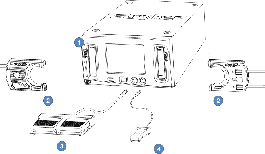
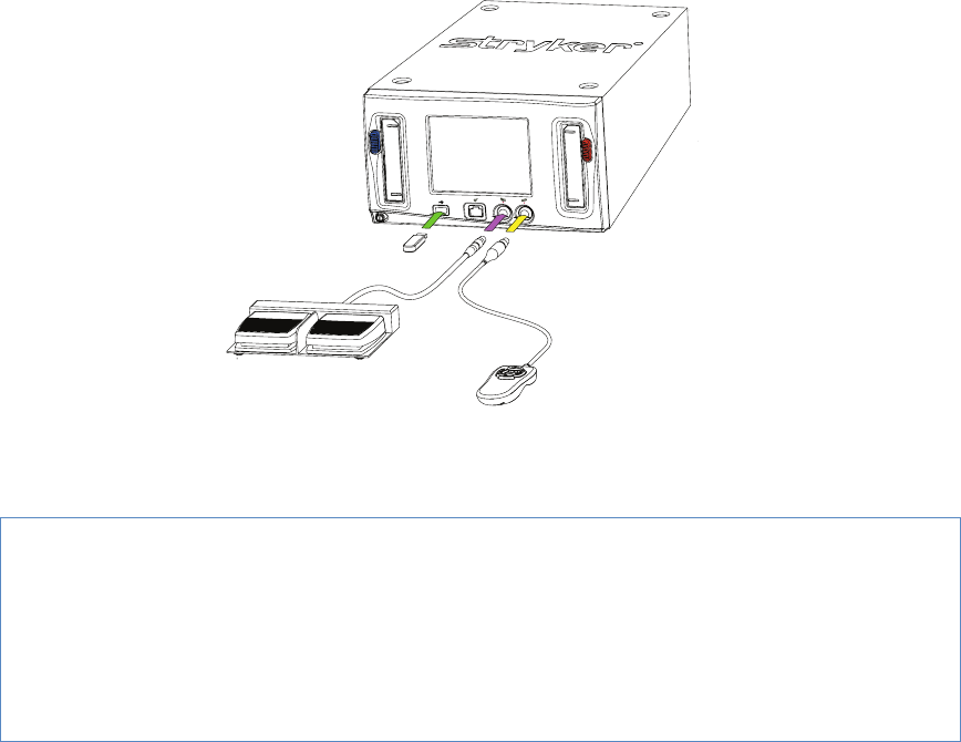
The Stryker CrossFlow Integrated Arthroscopy Pump is a uid management system� Illustrated below, the
system is composed of a pump console with inow-only and inow/outow modes, disposable cassette
tubing, a wired hand control, and a wired footswitch� The system integrates with approved resection
consoles�
1� CrossFlow Integrated Arthroscopy Pump (featured in this manual) - Compatible with the Crossre
Console, CrossFlow Footswitch, Autoclavable Hand Control, iSwitch Wireless Universal Foot Control,
Stryker rewire-compatible devices, and approved resection consoles�
2� CrossFlow Cassette Tubing - Compatible with the CrossFlow Integrated Arthroscopy Pump, 4-bag
adapter with inow cassettes, luer-lock connectors, standard irrigation uids, suction connectors, and
waste management systems� The user may elect to employ one of two modes of operation:
• Inow-Only Mode: utilizes only the inow function of the pump via the Inow Cassette Tubing or
the Day-Use Inow Cassette/Patient-Use Tubing
• Inow Cassette Tubing - The Inow Cassette Tubing transmits uid from saline bags to the
inow cannula at the surgical site and is disposed of after each case�
• Day-Use Inow Cassette/Patient-Use Tubing - The Day-Use Inow Cassette Tubing is used for
a single day’s cases, and the Patient-Use Tubing is connected to the Day-Use Inow Cassette
Tubing for a single case, then removed and discarded�
• Inow/Outow Mode: utilizes both the inow and outow functions of the pump via the Inow
Cassette Tubing and Outow Cassette Tubing�
3� CrossFlow Footswitch (optional) - Provides remote foot control of pump operation�
4� Autoclavable Hand Control (optional) - Provides remote hand control of pump operation�

EN-7
DRAFT
Indications
The CrossFlow Integrated Arthroscopy Pump is a dual arthroscopic pump system intended to provide uid
distension and irrigation of the knee, shoulder, hip, elbow, and ankle and wrist joint cavities and uid suction
during diagnostic and operative arthroscopic procedures�
Contraindications
The use of the CrossFlow Integrated Arthroscopy Pump is prohibited whenever arthroscopy is
contraindicated�
Package Contents
Carefully unpack the CrossFlow Integrated Arthroscopy Pump and ensure all components are accounted
for and remain undamaged from shipment� If damage to any component is detected, refer to the standard
warranty�
• (1) CrossFlow pump
• (1) Hospital power cord
• (2) Approved resection console power cord
• (1) User manual
• (1) Warranty and return policy
Part Numbers and Available Accessories*
The CrossFlow Integrated Arthroscopy Pump is featured in this manual� Refer to individual manuals for all
other products and accessories�
Part Number Description
0350220000 Autoclavable Hand Control*
0450000000 CrossFlow Integrated Arthroscopy
Pump
0450000100 CrossFlow Inow Cassette Tubing
0450000110 CrossFlow Day-Use Inow Cassette
Tubing
0450000120 CrossFlow Patient-Use Tubing
0450000200 CrossFlow Outow Tubing
0450000300 CrossFlow Integrated Cassette
Tubing
0450000500 CrossFlow Footswitch*
Approved Resection Consoles
The CrossFlow system is compatible with the following consoles� (Contact Stryker Endoscopy for
compatibility requirements for any non-approved resection consoles�)
• Arthrex APS II • Dyonics Power • Stryker CORE
• Arthrex OPES • Dyonics Power II • Stryker SERFAS
• Arthrocare ATLAS • Linvatec Advantage • Stryker TPS
• Arthrocare Quantum • Mitek VAPR
• Arthocare Quantum II • Smith and Nephew Vulcan
EN-8
DRAFT
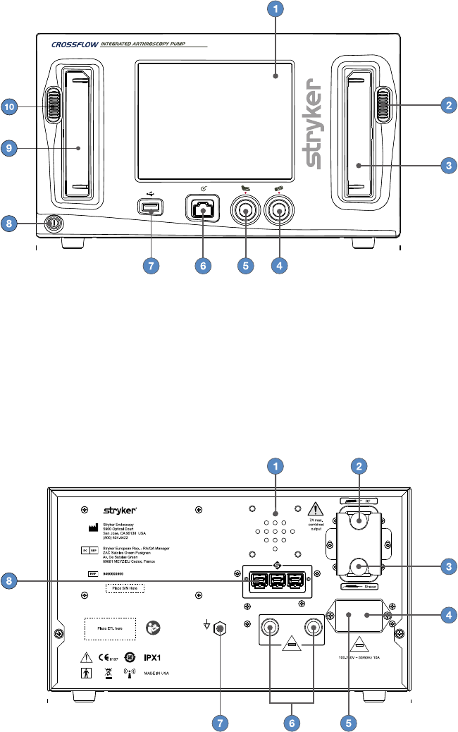
Front Panel
1� LCD Touchscreen 2� Outow Cassette Ejection Button
3� Outow Cassette Holder 4� Hand Control Receptacle
5� Footswitch Receptacle 6� Auxiliary Receptacle
7� USB Port 8� Power Button
9� Inow Cassette Holder 10� Inow Cassette Ejection Button
Rear Panel
T10A 250V T3A 250V
FCC ID: SSH-XFLOW
This device complies with part 15 of the FCC Rules. Operation is
subject to the following two conditions: (1) This device may not cause
harmful interference, and (2) this device must accept any interference
received, including interference that may cause undesired operation.
IC: 4919C-XFLOW
1� Speaker 2� Power Outlet for Approved Resection RF
Console
3� Power Outlet for Approved Resection
Shaver Console
4� AC Power Inlet
5� Fuse Drawer 6� Global Fuse Holders
7� Equipotentiality Ground Plug 8� SFB Connector Ports
EN-9
DRAFT
Setup and Device Conguration
Stryker Endoscopy considers instructional training an integral part of the CrossFlow system� Your Stryker
Endoscopy representative will perform at least one in-service at your convenience to help you set up your
equipment and instruct you and your sta on its operation and maintenance� Please contact your local
Stryker Endoscopy representative to schedule an in-service after your equipment has arrived�
1� Choose a location for the CrossFlow pump�
• Place the pump on a Stryker cart or other sturdy platform near a hospital grade outlet�
• Place the pump at the same height as the joint to ensure accurate pressure readings.
• Provide at least four to six inches of space around the sides of the pump to ensure proper ventilation
and allow access to the power cord�
Warning
RF and other mobile communications equipment may aect the normal function of the
CrossFlow pump� When placing the pump, follow the instructions located in the “Electromagnetic
Compatibililty” section of this manual�
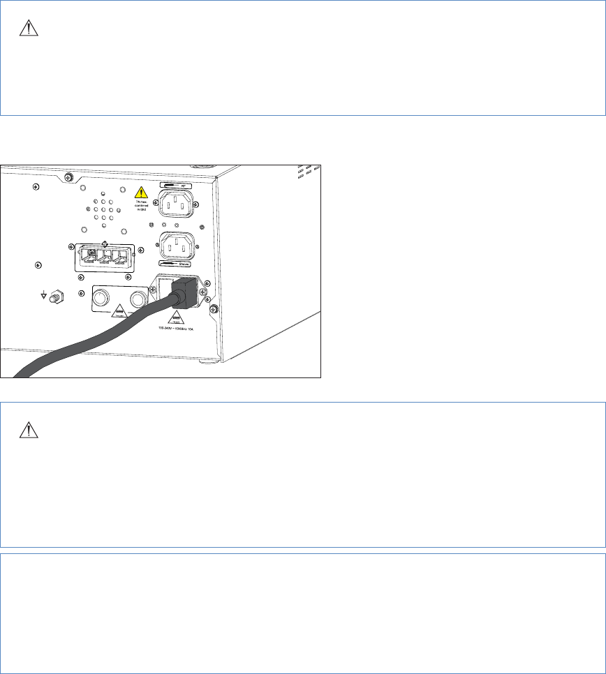
2� Connect the AC power�
• Connect the provided hospital power
cord to the AC inlet on the rear console
panel�
• Connect the other end to a hospital-grade
power outlet�
Warning
• Check the device label on the rear of the pump to determine the operating voltage of the
device�
• Check the power cord assembly periodically for damaged insulation or connectors�
• To avoid risk of electric shock, this equipment must only be connected to a supply mains with
protective earth�
Caution
• When connecting or disconnecting a cable, hold the cable by its connector (its plug, not the
cord)� Failure to comply may result in damage to the cable or pump�
• Connect the power cords directly to the AC inlet or outlet� Do not connect any of the power
cords together�
If required, connect the pump to a Stryker Firewire-compatible device using one of the SFB connector
EN-10
DRAFT
ports on each device�
Note: Refer to the manual supplied with each Firewire-compatible device for connection information�
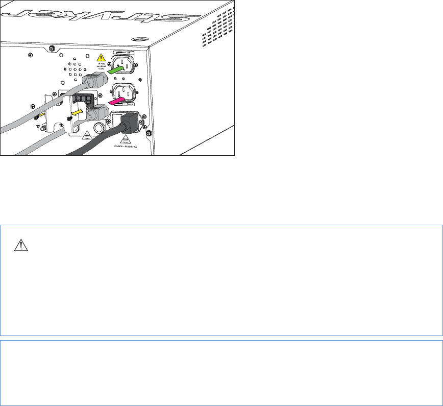
3� If required, connect the approved resection console(s) according to the interconnection diagram�
• Using a #1 Phillips screwdriver, unscrew
and remove the power cord bracket�
• Connect the approved resection power
cord to the AC inlet on the approved
resection console� Refer to the manual
supplied with each approved console for
connection information�
• Connect the other end to the power cord
to the power outlet for the approved
resection console on the rear panel of the
CrossFlow pump, as marked�
• Using a #1 Phillips screwdriver, attach and
secure the power cord bracket�
Note: The pump’s screen will display the specic components that are connected when the device is
powered on�
Warning
When the CrossFlow pump is interconnected with other electrical devices, leakage currents may
be additive, resulting in electromagnetic emissions that can interfere with the normal function
of electronic medical equipment� To properly control electromagnetic emissions and avoid
potential harm to the patient or user, ensure all electrical devices are installed and interconnected
according to the requirements of IEC 60601-1-1�
Caution
Ensure the approved resection consoles are connected to the correct power outlets on the rear
panel of the pump�
EN-11
DRAFT
4� If required, connect the hand control, footswitch, and/or USB drive according to the interconnection
diagram�
Note: Stryker recommends using the SIDNE USB2�0 Flash Disk, 512MB (P/N 0105-201-529)�
Note: The pump’s screen will display the specic components that are connected when the device is
powered on�
Caution
• Do not connect an ethernet cable to the auxiliary port�
• Turn the connector of the hand control and footswitch so that the red dot points up�
• Do not thread or twist the cable connector for insertion or removal� It is a push/pull connector
and may be damaged by twisting it into or out of place�
5� For tubing connection instructions, refer to the CrossFlow Inow and Outow Cassette Tubing and the
CrossFlow Day-Use Inow Cassette and Patient-Use Tubing manuals�
EN-12
DRAFT
Operation
Note: Refer to the “Symbols and Terminology” section in this manual for button and icon denitions and
commonly used terms�
Starting a Procedure
To start a procedure, perform the following steps:
1� Power the Pump On and O
2� Insert the Inow/Outow Cassette
3� Select the User Preference File
4� Select the Joint
5� Prime the Inow Tubing and Operate the Pump
Power the Pump On and O
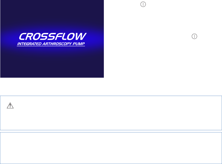
1� Press located at the bottom left corner of
the front panel to power on the pump� When
this button is illuminated by a green LED, the
system is powered on� The pump will display
a splash screen while the software is loading�
2� To power o the system, press again�
Insert the Inow/Outow Cassette
Warning
The choice of irrigation uid should be determined by the physician, based on the operation method
to be employed�
Caution
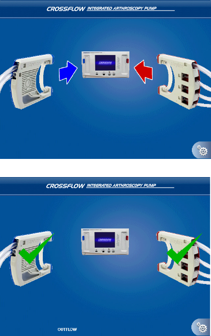
The cassettes are color-coded� When inserting the cassettes, make sure to insert them as indicated by
the color-coding�
EN-13
DRAFT
1� Align the colored side of the cassette(s)
with the colored button(s) on the pump as
depicted in the diagram� The Inow Cassette
is blue and the Outow Cassette is red�
2� Insert the cassette(s)� Push with your thumb
until it clicks into place�
• When the Inow Cassette is inserted,
a green check mark will appear on the
cassette, and the screen will advance to
the User Preference File Selection screen�
• When the Outow Cassette is inserted,
“Outow” will appear at the bottom of the
screen� A green check mark will appear
on the cassette if it is inserted before the
Inow Cassette (depicted in this scenario)�
3� Connect the tubing:
• For the Inow and Outow Cassette
Tubing, refer to the instructions in the
CrossFlow Inow and Outow Cassette
Tubing manual�
• For the Day-Use Inow Cassette
and Patient-Use Tubing, refer to the
instructions in the CrossFlow Day-Use
Inow Cassette and Patient-Use Tubing
manual�
Select the User Preference File
User preference les can be selected through the CrossFlow Pump interface� Select from “Standard Settings”
provided with the pump, or contact your Stryker representative to program your own, including settings for
pressure and ow rate and button assignments for the hand control and footswitch�
EN-14
DRAFT
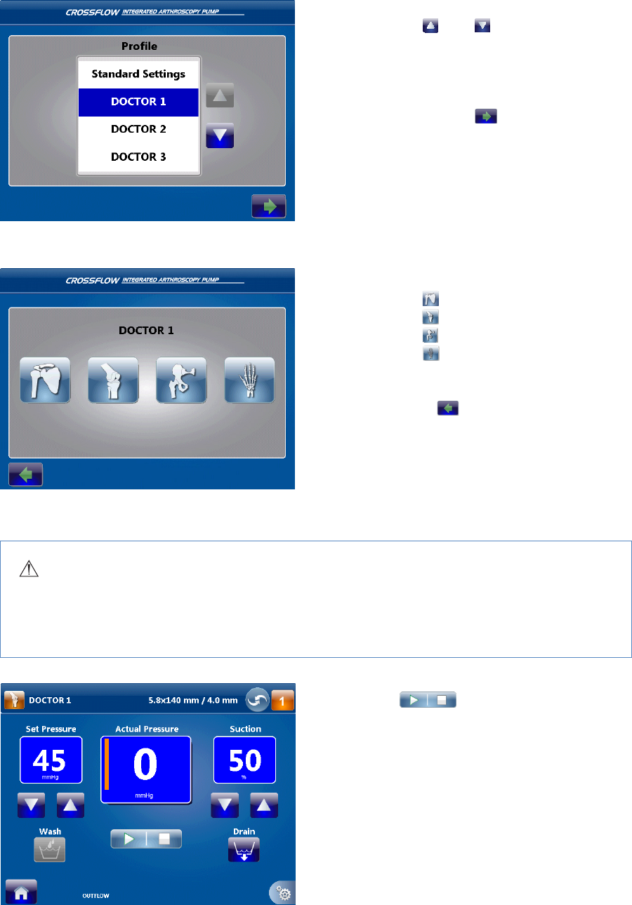
1� To scroll up and down the user preference le
list, press and �
2� Press the name of the desired user preference
le to highlight it�
In this scenario, “Doctor 1” is highlighted�
3� When the desired user preference le is
highlighted, press to conrm the
selection and advance to the next screen�
Select the Joint
1� Select the joint:
• Press to select the shoulder;
• Press to select the knee;
• Press to select the hip;
• Press to select the small joint�
2� When the desired joint is highlighted, the
screen will advance to the next screen�
Note: Press to return to the user
preference le selection screen�
Prime the Inow Tubing and Operate the Pump
Warning
• Start the pump with the inow tubing outside of the joint, all of the inow tubing clamps open,
and no hardware attached� Failure to remove air from the tubing can cause overpressure in the
joint�
1� Press to remove air from the
inow tubing�
Note: This step must be performed each time
a new Inow Cassette is inserted into the
pump�
EN-15
DRAFT
1� Press to remove air from the
inow tubing� The icon indicates that
the pump is operating�
Note: This step must be performed each time
a new Inow Cassette is inserted into the
pump�
2� Once the air has been removed and tubing is
completely lled with uid, close the pinch
clamps or stopcock�
3� Open the pinch clamps or stopcock to
proceed with pump operation�
4� Press to start/stop the pump�
During a Procedure
Changing the Pressure and Flow
Note: Follow these instructions to select or change pressure and ow settings if the user preference le does
not specify these settings� Adjusting the settings will override the default and user preference le settings�
The system will select the following default settings for the following application areas:
Joint Default Settings
Knee 45mmHg
Shoulder 50mmHg
Hip 50mmHg
Small 35mmHg
Note: Default pressure settings are only suggestions, and each procedure and each patient may require
dierent parameters� Select the optimal pressure based on the patient prole, including, but not limited to,
blood pressure, height, weight, age, and tissue quality�
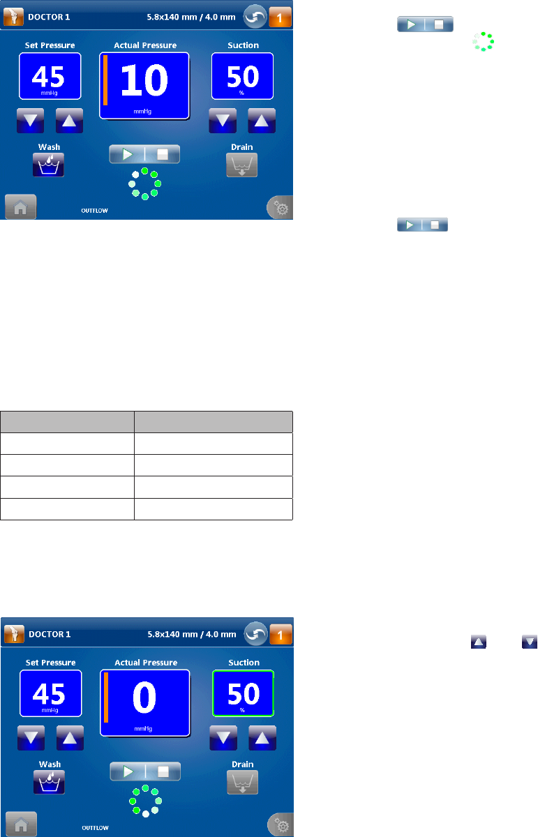
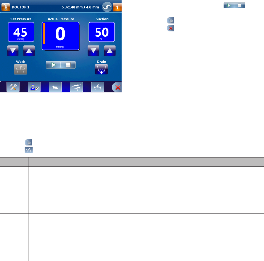
1� If necessary, press and to increase
or decrease the Set Pressure (adjust in
increments of 5mmHg from 15–150mmHg)
and Flow or Suction (adjust in increments of
10% from 0–100%)�
In this scenario, the pump is operating in
Inow/Outow mode� The Set Pressure is set
at 45mmHg, and the Suction is set at 50%�
Note: A green box will surround the suction/
ow value when the pump reaches the ow
limit� The pump is operating in constant ow
mode� Once the ow limit is reached, it will
operate in constant ow mode� (The pump
will attempt to operate at the set pressure
until the ow limit is reached�)
EN-16
DRAFT
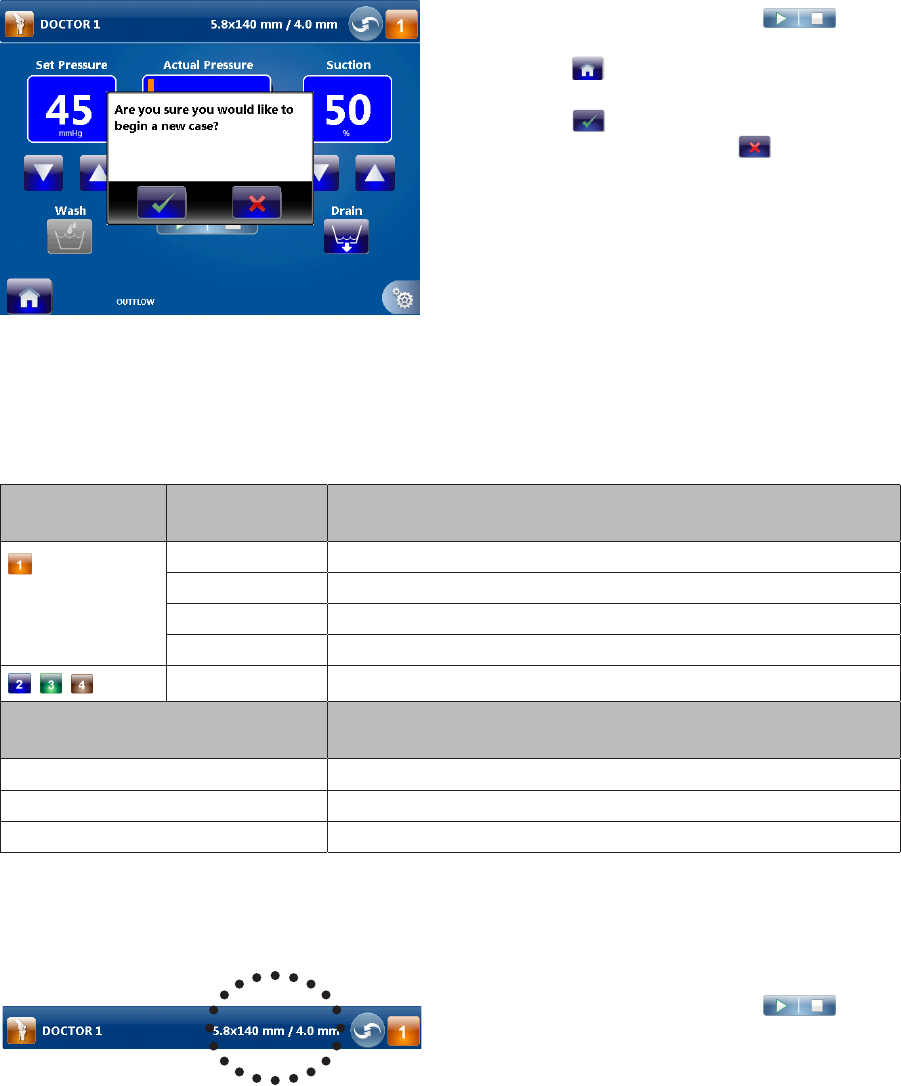
Changing the User Preference File or Joint Selections
1� If the pump is running, press to
stop the pump�
2� Press in the lower left-hand corner of
the screen�
3� Press to return to the user preference
le selection menu� Press to return to
the Run Screen�
4� Follow the instructions in the “Select the User
Preference File” and “Select the Joint” section
to change the user preference le and/or
joint�
Changing the Hardware Combination Selections
Note: Adjusting the settings will override the default and user preference le settings�
The system will select the following default hardware combination if “Standard Settings” is selected:
Hardware
option
Joint Default combination
Knee Stryker 5�8mmx140mm cannula with 4�0mm scope
Shoulder Stryker 5�8mmx140mm cannula with 4�0mm scope
Hip Stryker 5�0mmx165mm cannula (bridge) with 4�0mm scope
Small Stryker 4�0mmx75mm cannula with 2�7mm scope
— None
Alternate hardware combination
selections
Cannula diameter-scope diameter = x
Low Flow x ≤ 1
Medium Flow 1 > x ≥ 2
High Flow x > 2
Note: If the user preference le does not specify a hardware combination, follow these instructions to
change a hardware combination�
1� If the pump is running, press to
stop the pump�
2� Press the hardware combination selection to
return to the hardware combination selection
menu�
EN-17
DRAFT
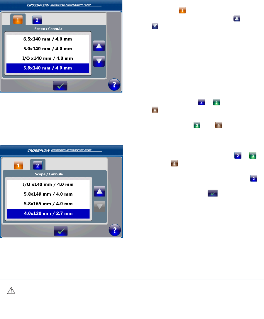
3� Select the scope/cannula combination
for option ; to scroll up and down the
hardware combination list, press and
�
4� Press the desired hardware combination to
highlight it�
In this scenario, “5�8mmx140mm cannula
with 4�0mm scope” is highlighted� (Select
Low, Medium, or High Flow if the desired
hardware combination does not appear on
the list�)
5� If no other hardware combination options are
required, proceed to step 6�
6� If necessary, press , , and/or
to view the available scope/cannula
combinations for these options�
Note: Hardware and are only
enabled if the hip joint is selected�
7� Repeat steps 3 and 4 to select the scope/
cannula combination for options , ,
and/or �
In this scenario, “4�0x120mm cannula with
2�7mm scope” is highlighted for option �
8� When the desired hardware combinations
are highlighted, press to conrm the
selections and advance to the Run screen�
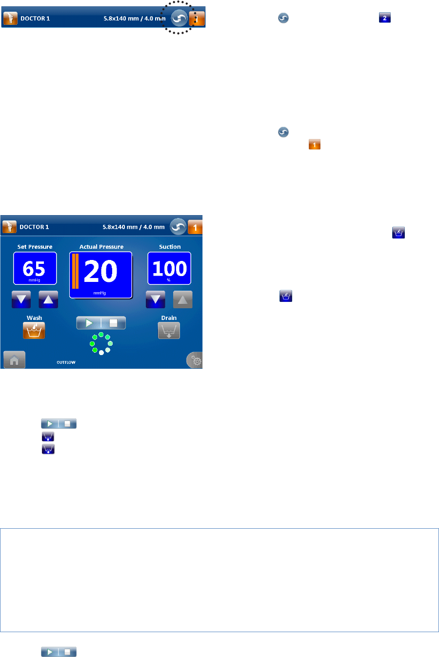
Swapping Between Hardware Combination Selections During the Case
The “Hot Swap” function allows the user to switch the cannula through which the inow tubing is attached
without requiring recalibration� Depending on the surgical site, up to four cannulas can be utilized by this
function�
Warning
Use the scope and cannula as selected on the pump� An incorrect scope and cannula selection may
cause overpressure in the joint�
EN-18
DRAFT
1� Press to change to option � A green
box will briey appear displaying the new
hardware combination selection�
2� Ensure the correct hardware combination
is displayed� If the incorrect hardware
combination selection is displayed, or to
change the hardware combination selection,
follow the instructions in the “Change
Hardware Combination Selections” section�
3� Press to change to hardware
combination �
Performing the Wash Function
The Wash function increases the set pressure and ow limit by a user-specied percentage over a user-
specied duration (for Inow-only mode), or increases set pressure and suction by a user-specied
percentage over a user-specied duration (for Inow/Outow mode)�
1� While the pump is running, press to
perform the Wash function� Follow the
instructions in the “Program the Wash and
Clear Function Settings” section to adjust the
default settings�
2� Press to repeat or stop the Wash
function�
Performing the Drain Function
The Drain function is only available in the Inow/Outow mode� It operates the outow pump to remove
uid from the surgical site for 30 seconds or until the user stops the pump�
1� Press to stop the pump�
2� Press to remove uid from the joint�
3� Press to repeat or stop the Drain function�
After a Procedure
Remove the Cassettes
Caution
• Do not remove the cassettes while the pump is in use� The pump or the cassette may be damaged�
The cassettes can only be removed when the pump is stopped�
• Do not attempt to remove the Outow Cassette if it gets stuck as it may damage the pump or the
cassette� Follow the instructions in the “Troubleshooting” section in this manual to resolve this
problem�
1� Press to stop the pump�
2� Close all pinch clamps�
EN-19
DRAFT
3� Refer to the CrossFlow Day-Use Inow Cassette and Patient-Use Tubing and the CrossFlow Inow and
Outow Cassette Tubing manual on instructions on how to disconnect and discard the tubing� Always
maintain a sterile technique�
4� Press the Inow Cassette Ejection button (blue) and/or the Outow Cassette Ejection button (red) on the
front panel of the pump to eject the cassette(s)�
5� Discard the cassettes and tubing appropriately�
EN-20
DRAFT
Menu Features
Opening and Closing the Main Menu
1� If the pump is running, press to
stop the pump�
2� Press to open the Main Menu�
3� Press to close the Main Menu�
Programming the Wash and Clear Functions Settings
Note: Adjusting the settings will override the default and user preference le settings�
1� Press to open the Main Menu�
2� Press to open the Wash and Clear Settings Menu�
Setting Function
Wash • Inow-only mode: Increases set pressure and ow limit by user-specied percentage over
user-specied duration� By default, the set pressure will increase by 50% of the current
setting, and the ow limit will increase by 100% of the current setting for 30 seconds�
• Inow/Outow mode: Increases set pressure and suction by user-specied percentage
over user-specied duration� By default, the set pressure will increase by 50% of the current
setting, and the suction will increase by 100% of the current setting for 30 seconds�
Clear • Inow-only mode: Increases ow limit by user-specied percentage over user-specied
duration� By default, the ow limit will increase by 100% of the current setting for 30
seconds�
• Inow/Outow mode: Increases suction rate by user-specied percentage over user-
specied duration� By default, the outow will increaseby 100% of the current setting for
30 seconds�
EN-21
DRAFT
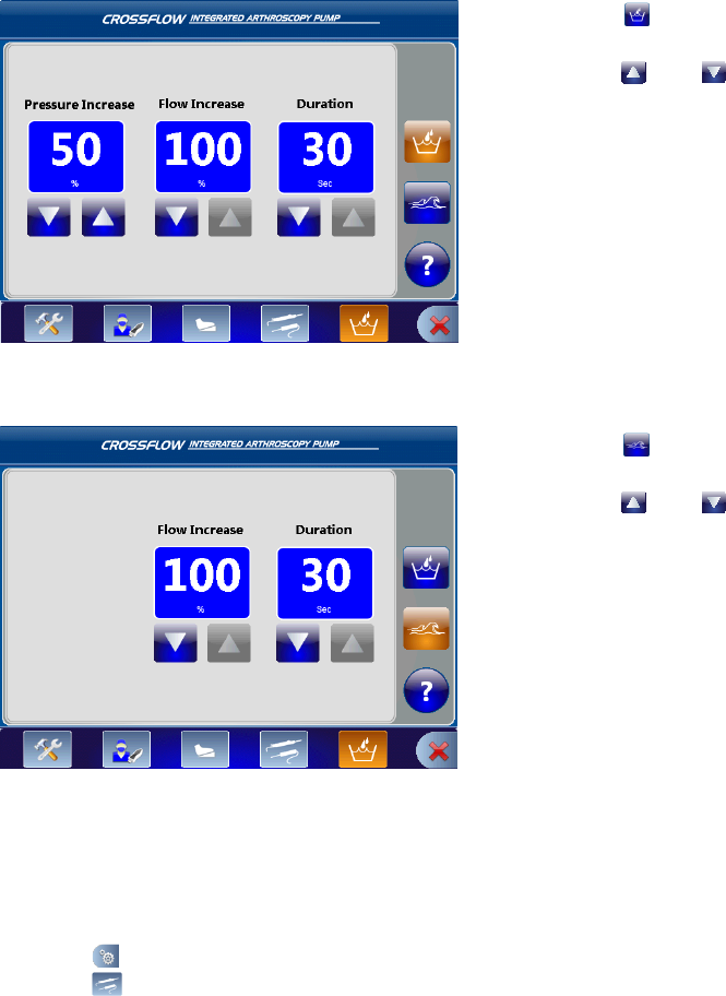
Wash Function Settings
1� Press to program the settings for the
Wash function�
2� Press and to adjust the Pressure,
Flow, or Duration�
In this scenario, the pressure will increase by
50% and the ow will increase by 100% for 30
seconds�
Clear Function Settings
1� Press to program the settings for the
Clear function�
2� Press and to adjust the Flow or
Duration�
In this scenario, the ow will increase by 100%
for 30 seconds�
Programming the Resection Integration Settings
Note: Adjusting the settings will override the default and user preference le settings�
1� Press to open the Main Menu�
2� Press to open the Resection Integration Settings Menu�
EN-22
DRAFT
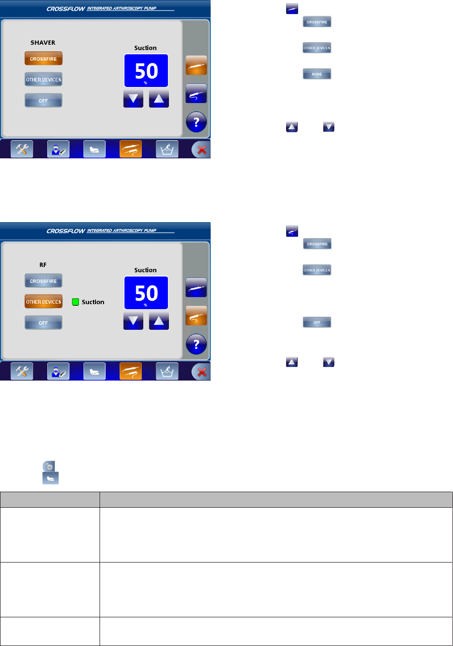
Shaver Console Settings
1� Press to specify the shaver console:
• Press to select the CrossFire
console;
• Press to select an approved
resection console;
• Press if no shaver console is in
use�
In this scenario, the CrossFire console is
selected�
2� Press and to increase or decrease
the Suction (adjust in increments of 10% from
0–100%)�
In this scenario, the Suction is set at 50%�
RF Console Settings
1� Press to specify the RF console:
• Press to select the CrossFire
console;
• Press to select an approved
resection console
(Press “Suction” if the RF probe is a suction
probe�);
• Press if no RF console is in use�
In this scenario, an approved resection
console with a suction probe is selected�
2� Press and to increase or decrease
the Suction (adjust in increments of 10% from
0–100%)�
In this scenario, the Suction is set at 50%�
Programming the Footswitch and Formula Shaver Settings
1� Press to open the Main Menu�
2� Press to open the Footswitch/Formula Shaver Settings Menu�
Setting Function
Wash • Inow-only mode: Increases set pressure and ow limit by user-specied
percentage over user-specied duration�
• Inow/Outow mode: Increases set pressure and suction by user-specied
percentage over user-specied duration�
Clear • Inow-only mode: Increases ow limit by user-specied percentage over user-
specied duration�
• Inow/Outow mode: Increases the suction by user-specied percentage over
user-specied duration�
Drain • Operates the outow pump to remove uid from the surgical site for 30
seconds or until the user stops the pump�
EN-23
DRAFT
Pressure Up/Down • Increases/decreases the set pressure�
Hot Swap • Switches between selected arthroscope/cannula combinations�
Start/Stop • Starts/stops the pump�
Flow Up/Down • Inow-only mode: Increases/decreases the ow limit�
• Inow/Outow mode: Increases/decreases suction�
None • No function�
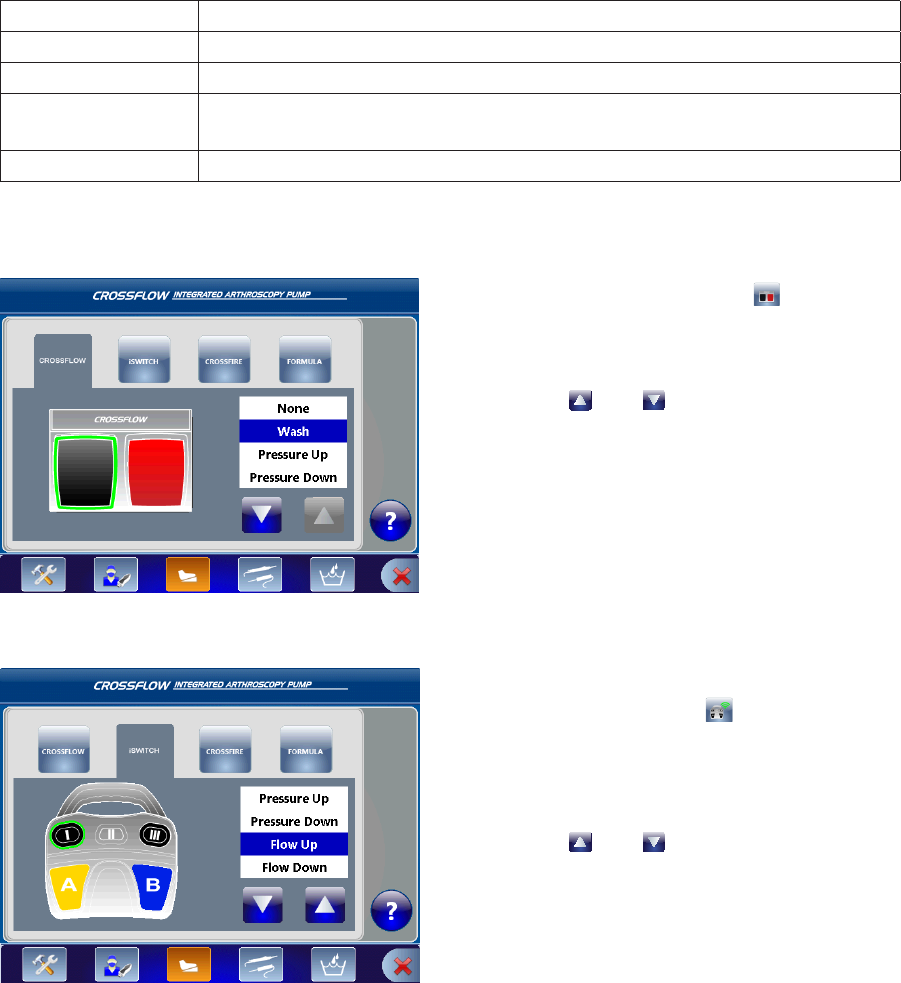
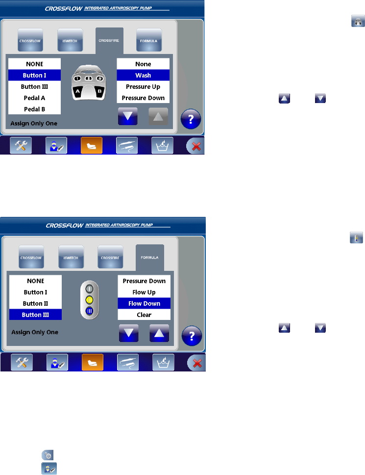
CrossFlow Footswitch
1� Press the CrossFlow button to program
settings for the CrossFlow Footswitch�
2� Press the black foot pedal (highlighted with
green border) to select its function�
3� Press and to scroll up and down the
function list�
4� Press the function of choice to assign the
function to the pedal�
In this scenario, the “Wash” function is
selected�
5� Repeat steps 2–4 to program the red foot
pedal�
iSwitch Footswitch
1� Press the iSwitch icon to program
settings for the iSwitch Footswitch�
2� Press the appropriate button/pedal
(highlighted with green border) to select its
function�
3� Press and to scroll up and down the
function list�
4� Press the function of choice to assign the
function to the button/pedal�
In this scenario, the “Flow Up” function is
selected for Button I�
5� Repeat step 2–4 to program each button/
pedal�
EN-24
DRAFT
Crossre Footswitch
1� Press the Crossre icon to program
settings for the Crossre Footswitch�
2� Select a button/pedal in the left-hand menu
to program it�
Note: Only one button or pedal may be
assigned a function�
3� Press and to scroll up and down the
function list�
4� Press the function of choice to assign the
function to the button/pedal�
In this scenario, the “Wash” function is
selected for Button I�
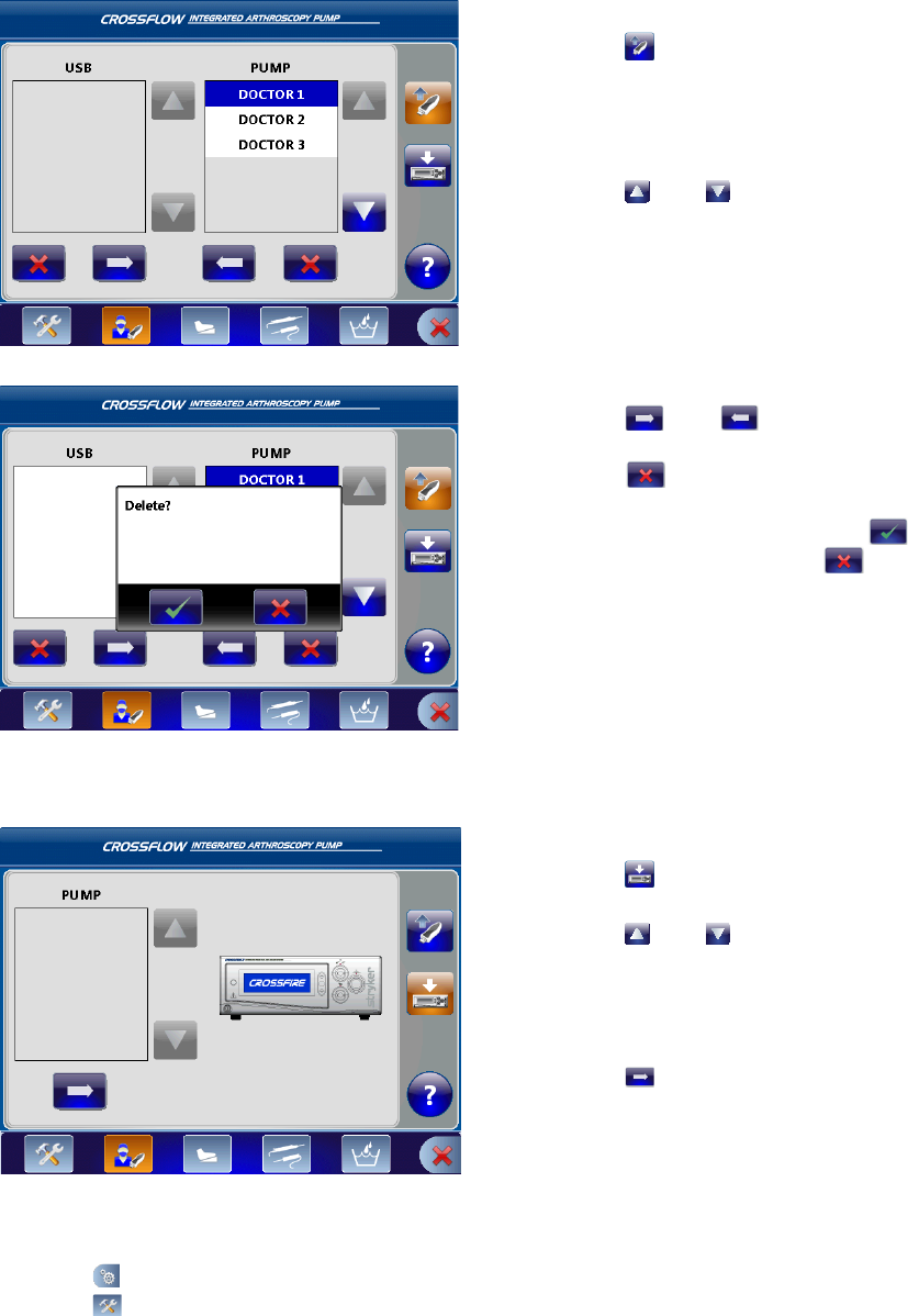
Formula Shaver
1� Press the Formula icon to program
settings for the hand control�
2� Select a button in the left-hand menu to
program it�
In this scenario, Button III is selected�
Note: Only one button or pedal may be
assigned a function�
3� Press and to scroll up and down the
function list�
4� Press the function of choice to assign the
function to the button/pedal�
In this scenario, the Flow Down is selected for
Button III�
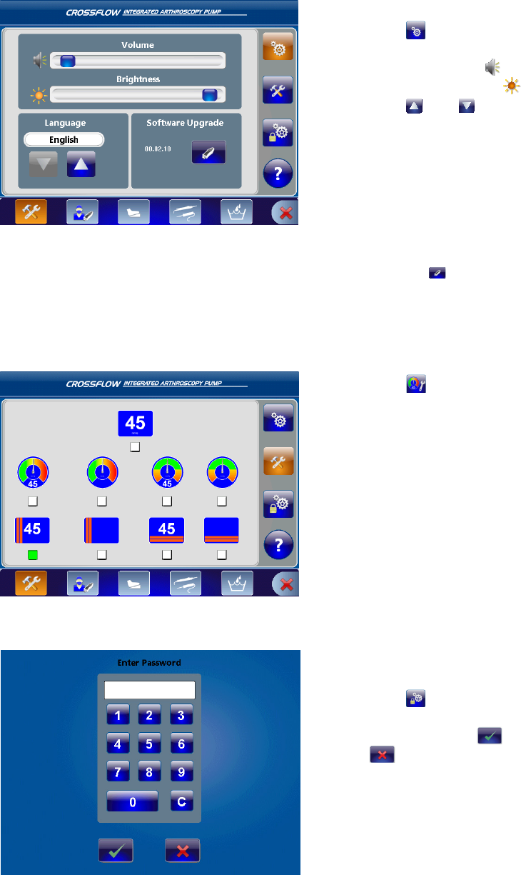
Loading User Preference Files
1� Press to open the Main Menu�
2� Press to open the User Preference Menu�
EN-25
DRAFT
Transferring Files to/from a USB drive
1� Press to upload/download les to/from a
USB drive�
2� Connect the USB drive according to the
instructions in the “Setup and Device
Conguration” section�
3� Press and to scroll up and down the
le list�
4� Select the le to transfer or delete�
In this scenario, the “Doctor 1” le is selected�
5� Press and to transfer les to/from
the USB drive to/from the pump�
6� Press below the USB or pump list to
delete the selected le�
7� To delete the selected le, press � To
cancel the operation, press �
Transferring Files to the Crossre System
1� Press to transfer a user preference le to
the Crossre system�
2� Press and to scroll up and down the
le list�
3� Select the le to transfer�
Note: Only preference les containing
Crossre settings will appear in this menu�
4� Press to transfer the le to the Crossre
system�
Navigating to the Settings Menu
1� Press to open the Main Menu�
2� Press to open the Settings Menu�
EN-26
DRAFT
Adjusting the Volume, Brightness, and Language, and Upgrade Software
1� Press to open the General Settings
Menu�
2� Adjust the Volume �
3� Adjust the Brightness �
4� Press and to select the language
preference�
5� To upgrade the software:
• Connect the USB drive according to the
instructions in the “Setup and Device
Conguration” section� The current
software version appears in the box�
In this scenario, version 00�02�10 is
installed�
• Press to upgrade the software� The
system will automatically restart once the
software is succesfully upgraded�
Adjusting the Actual Pressure Display
1� Press to open the Actual Pressure Display
selection menu�
2� Select the desired display icon� The selection
will be highlighted with a green box�
Accessing the Stryker Settings Menu (For Stryker use only)
Only authorized Stryker representatives have
access to this menu�
1� Press to open the Stryker Settings Menu�
2� Enter a password�
3� To conrm, press � To cancel, press
�

EN-27
DRAFT
Navigating to the Help Menu
1� Press to open the Help Menu on any screen�
System Feedback
Audible Feedback
Audible Feedback Event Implication
Three high-tone beeps Fault error Refer to “Error Messages”
Three high-tone beeps,
pause, two beeps
Lockdown error Refer to “Error Messages”
One medium-tone
beep
Accessory connection Refer to “Connect the Components” and “Insert
the Inow/Outow Cassette”
Two medium-tone
beeps
Accessory removal Refer to “Connect the Components” and “Insert
the Inow/Outow Cassette”
One low-tone beep Touchscreen/Hand control/
Footswitch operation
N/A
Three (medium, low,
high-tone) beeps
Hot swap Refer to “Swap between Hardware Combination
Selections”
Error Messages
The words caution, fault, and lockdown carry special meanings and should be carefully reviewed:
• Caution: Visual popup error is displayed for ve seconds; user may clear the message when the problem
is resolved�
• Fault: The pump will stop; user may clear the message when the problem is resolved�
• Lockdown: The pump will stop; reboot system�
Error Message Cause Possible Solution
CAUTION Cassette about to expire (two hours left
before expiration)�
• Replace the cassette�
CAUTION Preventative Maintenance required; the
unit has reached its recommended service
interval�
• Contact your Stryker
representative�
CAUTION Inow/Outow RFID read failure: The
Inow or Outow RFID tag cannot be
detected while the pump is stopped�
• Ensure the Inow or Outow
Cassette is fully inserted�
• If the problem persists, replace
the cassette�
• If the problem persists, contact
your Stryker representative�
FAULT Priming Error: No uid in the tubing after
ten seconds�
• Ensure the pinch clamps on the
saline bags are open�
• Ensure the Inow Cassette is
fully inserted�

EN-28
DRAFT
Error Message Cause Possible Solution
FAULT Instrument recognition error: The stopcock
on the cannula is closed, the lower clamp
on inow tubeset is closed, or no hardware
is attached to the tubing�
• Check the inow tubing
from the bags to the joint
and ensure the hardware is
properly attached�
• Open any closed clamps or
stopcocks�
• Repeat the priming step�
FAULT Inow and/or Outow Cassette not fully
inserted�
• Remove and reinsert the
cassette until it clicks into
place�
FAULT Cassette is expired (after 24 hours of use)� • Replace the cassette�
FAULT The connection to the Crossre console or
approved resection console is lost�
• Ensure the consoles are
properly connected to the
pump� Follow the instructions
in the “Setup and Device
Conguration” section in this
manual�
• Reboot the system�
• If the problem persists, contact
your Stryker representative or
return the console for repair�
FAULT The Crossre console is specied in the
user preference le, but it is improperly or
not connected to the pump�
• Ensure the console is properly
connected to the pump� Follow
the instructions in the “Setup
and Device Conguration”
section in this manual�
• Reboot the system�
• If the problem persists, contact
your Stryker representative or
return the console for repair�
LOCKDOWN Hardware fault detected • Reboot the system�
• If the problem persists, contact
your Stryker representative or
return the console for repair�
LOCKDOWN Motor defective • Reboot the system�
• If the problem persists, contact
your Stryker representative or
return the console for repair�
LOCKDOWN Pressure Transducer out of calibration:
If the pressure is at a value greater than
20mmHg for ve seconds when no
cassette is inserted�
• Reboot the system�
• If problem persists, contact
your Stryker representative�
LOCKDOWN Possible Overpressure: The pressure is
sustained at 750mmHg for more than one
second, or a hardware failure or pressure
transducer malfunction has occurred�
• Reboot the system�
• If the problem persists, contact
your Stryker representative or
return the console for repair�

EN-29
DRAFT
Troubleshooting
Problem Cause Possible Solution
The pump does not
power on (no approved
resection console(s) are
attached to the pump)�
The pump is not plugged in, or the
global or main fuses are out�
• Ensure the pump is plugged in to the
main outlet�
• Inspect the all fuses�
• Replace the fuse if it is out of service�
The pump does not
turn on (approved
resection console(s) are
attached and turn on)�
There is a power supply failure, or the
main fuses are out�
• Inspect the main fuses in the fuse
drawer�
• Replace the fuses if it is out of service�
• If the problem persists, contact your
Stryker representative�
The pump turns on,
but approved resection
console(s) do not�
There is a problem with the approved
resection console(s)�
• Inspect the approved resection
console(s)�
• If the problem persists, contact your
Stryker representative or return the
console for repair�
Neither the pump or
approved resection
consoles turn on�
The pump is not plugged in, or the
main fuses are out�
• Ensure the pump is plugged in to the
main outlet�
• Inspect the main fuses in the fuse
drawer�
• Replace the fuses if they are out of
service�
The pump is plugged
in, the fuses are
functional and/or have
been replaced, and the
pump still does not
turn on�
A hardware error occurred� • Plug the pump in to a dierent main
outlet�
• If the problem persists, contact your
Stryker representative�
The cassette(s) are
inserted, but the Run
Screen does not appear,
and the pump does not
start�
The Inow or Outow RFID tag cannot
be detected�
• Ensure the Inow or Outow Cassette is
fully inserted�
• If the problem persists, replace the
cassette�
• If the problem persists, contact your
Stryker representative�
The pump turns on, but
there is no image on
the screen or the screen
is frozen�
A hardware error occurred� • Reboot the system�
• If the problem persists, contact your
Stryker representative�
The hand control or
the footswitch are
plugged in, but are not
activating�
The devices are improperly connected
to the pump�
• Ensure the devices are properly
connected according to the
instructions in the “Setup and Device
Conguration” section of this manual�
The settings in the Footswitch/Formula
Shaver Settings Menu are set to “None�”
• Check the settings in the Footswitch/
Formula Shaver Settings Menu�
• Reset the settings to the Default
settings�
The device(s) have reached their
expected lifetime�
• Replace the device(s)�

EN-30
DRAFT
There are abnormal
pressure or ow rate
uctuations�
There is a pressure sensor error� • Reboot the system�
• If the problem persists, contact your
Stryker representative, or return the
console for repair�
A hardware fault is detected�
The pump stops
pumping uid, and
the pressure indicator
continues to blink�
The pressure is too high� The actual
pressure exceeds 200mmHg for
15seconds or greater than 250mmHg
for ve seconds�
• Open the valve at the outow tube, the
drainage tube, or the stopcock on the
instrument to reduce the pressure�
The pinch valves are
not engaging�
There is a pinch valve or hardware
error�
• Examine the pinch valves to ensure
they are functioning properly�
• Reboot the system�
Bubbles appear in the
joint�
There is no more irrigation uid� • Replace or add additional saline bags�
• Ensure the pinch clamp is open on the
irrigation tube, or the stopcock is open�
The tubing connection is loose� • Ensure the tubing is securly connected�
• If the problem persists, replace the
tubing�
A priming error occurred� • Ensure the pinch clamps on the saline
bags are open�
• Ensure the Inow or Outow Cassette is
fully inserted�
• Remove the hardware from the tubing
and repeat the priming step�
• If the problem persists, replace the
cassette�
The suction level is set too high� • Decrease the suction level�
The pump cannot
achieve the set
pressure�
There is a hardware setup error, the
ow limit is set too low, or the suction
level is set too high�
• Verify the luer-lock is tightly closed,
the correct hardware is selected and
properly connected, and the dual
stopcock cannula is properly set up�
• Increase the ow limit or the set
pressure setting�
• Decrease the suction level�
• Press Run/Stop to restart the pump�
There is insucient
pressure in the surgical
site�
An irrigation problem exists� • Check the stopcock on the arthroscope
and the clamps under the saline bags�
The hardware set up is incorrect� • Ensure the hardware is properly
selected and set up�
There is no suction
while the pump is
running�
The approved resection consoles are
improperly connected�
• Ensure the consoles and the tubes
are properly connected according to
the instructions in Setup and Device
Conguration section of this manual�
The tubes on the Outow Cassette are
improperly connected�
Unable to upload les
to/from USB drive�
A hardware fault occurred� • Ensure the USB drive is functioning
properly and the correct les are on
the drive� If the drive is not functioning
properly, replace the USB drive�
• Reboot the system�

EN-31
DRAFT
Sporadic electrical
interference is aecting
the pump�
Electrical, RF, and/or mobile
communications equipment is
aecting the normal function of the
pump�
• Power down all electrical equipment
not in use�
• Increase the distance of other electrical
equipment�
• Connect the pump and other
equipment into dierent outlets�
The touch screen
is unresponsive or
inaccurate�
Touch screen is not properly calibrated
for the user�
• Reboot the system�
• If the problem persists, contact your
Stryker representative or return the
console for repair�
A hardware or software error occurred�
A user preference
le was accidentally
deleted from the pump�
Unintentional deletion of a user
preference le�
• Transfer the user preference le from
a USB drive to the pump according to
the instructions in the “Transfer Files
to/from a USB drive” section of this
manual�
The pump is stopped,
but the Outow
Cassette is stuck and
cannot be ejected�
The pinch valves do not retract� • Do not attempt to remove the cassette
as it may damage the pump or the
cassette�
• Reboot the system�
• If the problem persists, contact your
Stryker representative�
“Service Pump Soon” The pump is 95% through the current
maintenance period�
• Contact your Stryker service
representative�

EN-32
DRAFT
Cleaning, Maintenance, and Disposal
Warning
• Do not remove the cover of the console as this could cause electric shock and product damage.
• To avoid electric shock and potentially fatal injury, unplug the pump from the electrical outlet
before cleaning�
Caution
To prevent product damage:
• when cleaning the pump, do not spray cleaning liquid directly onto the pump; spray on the cloth
before wiping the pump,
• do not immerse the pump in any liquid,
• do not use corrosive cleaning solutions to clean the pump,
• do not sterilize the pump�
Clean the Components
Pump
Should the pump need cleaning:
1� Spray cleaning liquid onto a dry, sterile cloth� Avoid excess liquid or drips�
2� Wipe the pump�
3� Take extra care when cleaning the front LCD screen� Excess liquid or drips that enter the bottom of the screen
may result in product damage�
Footswitch
Warning
Clean the footswitch prior to rst use and after every subsequent use�
Consult the footswitch manual (P17862) for cleaning instructions�
Hand control
Warning
Clean and sterilize the hand control prior to rst use and after every subsequent use to minimize risk
of infection�
Consult the hand control manual for cleaning and reprocessing instructions�
Replace the Fuses
1� Disconnect the pump from the electrical output and remove the power cord from the rear of the pump�
2� Remove the appropriate fuse holder; with a straight blade screwdriver, unlatch the fuse drawer, or turn the
global fuse holders in a counter clockwise direction until the spring pushes out�
3� Remove the fuse(s)�
4� Replace the fuse(s) with a fuse of the same value and rating as indicated on the rear of the pump�
EN-33
DRAFT
5� Follow these steps in reverse for assembly�
• Push in the the fuse drawer until it clicks into place�
• Turn the global fuse holders in a clockwise direction until they are fully pushed in and secure in their
original position�
Perform Annual Inspection
Stryker recommends inspections of the system on an annual basis� These inspections evaluate whether the
product currently or in the near future may fail in a manner that aects device performance�
Safety Test
Visually inspect the device and its components to ensure the:
• fuses correspond with the specications on the pump,
• labels and device markings are legible,
• mechanical condition of the system (wires, hardware, etc�) allows for its safe use, and
• the system is clean for safe and proper use�
Basic Function Test
Perform a basic function test to analyze the features, displays, and performance of the system�
1� Power
• Power on the pump according to the instructions in “Power the CrossFlow Pump On and O” section
of this manual� The power button will be illuminated by a green LED, indicating the system has
powered on�
2� Stepper motor
• Insert the cassettes according to the instructions in “Insert the Inow/Outow Cassette” section of
this manual�
• Visually inspect the stepper motors located in the cassette holder; they will be disengaged�
• Remove air from the inow tubing according to the instructions in “Prime the Inow Tubing” section
of this manual�
• Visually inspect the stepper motors; two motors will be engaged�
• Stop the pump�
• Visually inspect the stepper motors; they will be disengaged�
• Remove the cassettes according to the instructions in “Remove the Cassettes” section of this manual�
3� Device Detection
• Connect the components (for example, the hand control, footswitch, CrossFire system, etc�)
according to the instructions in “Connect the Components” section of this manual�
• Ensure the console displays the icon in the bottom of the screen of each component that is
connected when the device is powered on�
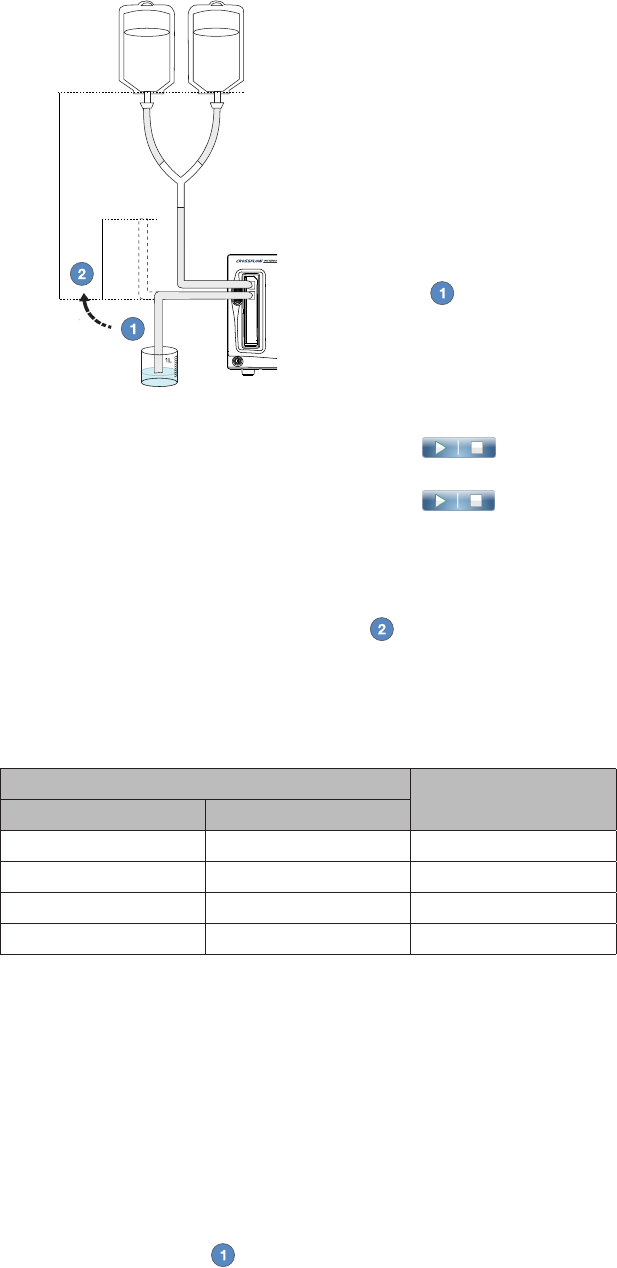
4� Pressure Sensor
EN-34
DRAFT
h
1 m / 39 in
• Gather the following equipment:
• disposable Inow Cassette tube set
• container lled with water
• uid bag (3L)
• Follow the instructions in this manual to power on the pump,
insert the Inow Cassette, select a preference le, and select a
joint�
• Suspend a uid bag 1m/39in on its holder and connect the
bag to the tubing according to the diagram�
• Discard the protective cap on the tubing (if needed), and
immerse the end of the tubing into a container lled with
water�
• Set the Pressure to 50mmHg and Flow to 20%, according to the
instructions in the “Set the Pressure and Flow” section of this
manual�
• Remove air from the inow tubing according to the instructions
in the “Prime the Inow Tubing” section of this manual�
• Press to start the pump� Allow the tubing to
completely ll with uid�
• Press to stop the pump� The actual pressure display
will show approximately 0–5 mmHg�
• Remove the tubing from the container and hold it at a given
water column height (h) indicated in the table below� Ensure
the tubing in the water column is completely lled with uid�
• Read the actual pressure displayed on the pump� The test has
been successfully completed if the actual pressure on the pump
is within the range indicated in the table below for a given
height of the water column�
Height of water column (h) Acceptable actual
pressure (mmHg)
Inches Centimeters
12 30 20–25
18 45 30–35
24 60 40–45
46 90 65–70
5� Inow Flow Rate
• Gather the following equipment:
• disposable Inow Cassette tube set
• uid bag (3L)
• stopwatch
• one 1L measuring cup
• Follow the instructions in this manual to power on the pump, insert the Inow Cassette, select a
preference le, and select a joint�
• Suspend a uid bag 1m/39in on its holder and connect the bag to the tubing according to the
diagram�
• Discard the protective cap on the tubing (if needed), and place the end of the tubing into a container
lled with water�
• Set the pressure to 150mmHg and ow to 50%�
• Remove air from the inow tubing according to the instructions in the “Prime the Inow Tubing”
section of this manual�
• Clamp o the tubing in the measuring cup without stopping the pump�
EN-35
DRAFT
• Empty the measuring cup�
• Unclamp the tubing and place it in the cup� Start the stopwatch once the tubing is placed back in
the cup�
• Once the measuring cup is lled with 1 liter of uid, press to stop the pump�
• The test has been successfully completed if the time it takes to ll the measuring cup with 1 liter of
uid is within the range specied in the table below�
Flow (%) Time (seconds)
50 70
Perform Preventive Maintenance and Calibration
Caution
Stryker does not accept any liability for direct or consequential damages if:
• the pump or the accessories are improperly prepared and maintained,
• non-authorized persons perform repairs, adjustments, or alterations to the pump or accessories,
• non-authorized persons open the pump,
• the prescribed inspection and maintenance schedules are not followed�
When the pump is 95% through the current maintenance period, a “Service Pump Soon” notication
will appear on the screen� An authorized Stryker service technician must inspect and service the device
according to the maintenance and calibration schedule below to maintain product functionality�
Component Maintenance/Calibration Period
Motors 2years
Pinch valves 2years
Pressure transducer 2years
Expected Life
Equipment Expected Life
Console Fiveyears
Footswitch Threeyears
Hand Control Oneyear
Inow, outow, patient-use tubing Single-use
Day-use cassette Tencases, eighthours of active use, or 24hours after point of rst
use
Disposal
This product contains electrical waste or electronic equipment� It must not be disposed of as unsorted
municipal waste and must be collected separately in accordance with applicable national or institutional
related policies relating to obsolete electronic equipment�
Dispose of any system accessories and irrigation uid according to normal institutional practice relating to
potentially contaminated items�

EN-36
DRAFT
Technical Specications
Equipment Information
Size Pump Dimensions:
• 12�528in� (318�2mm) width
• 7�025in� (178�4mm) height
• 16�990in� (431�6mm) depth
Pump Weight: 24lbs� (10�9kg)
Hospital power cord: (p/n 0105-033-001) 2m
Approved resection console power cord: (p/n P17275) 2m
Power
Connection
Input Voltage: 80–275V
Inlet Fuse: 10A, 250V
Frequency 47–63Hz
Power/Current
Consumption
Maximum power consumption: 269W
Maximum current consumption: 80V: 3�4A; 275V: 0�98A
Motor output maximum speed: 650RPM
RF output waveform: 13�56MHz (ISO15693)
Electrical Safety
Classication
Class I equipment
Type BF Part
Water ingress protection, IPX1
Continuous Operation
Environmental
Specications
Operating Temperature: 5 – 40°C
Operating Humidity: 30 – 95% RH (non-condensing)
Shipping Temperature: -18° – 60°C
Shipping Humidity: 15 – 90% RH
Safety and EMC
Compliance
• UL 60601-1: 2006
• IEC 60601-1-2: 2007
• IEC 60601-1-4: 2000
• IEC 60601-1-6: 2010
• IEC 60601-1-8: 2006
• IEC 62304: 2006
• IEC 62366: 2007
• CAN/CSA-C 22�2 No� 601�1-M90: 2003
• CAN/CSA 22�2 No� 60601-1: 2002
• AS/NZS 3200�1�0: 1998
• IEC 60601-1: 2005 + Corr 2006 + Corr 2007
• IEC 60601-1-1: 2005 + Corr 2006 + Corr 2007
• CAN/CSA-C 22�2 No� 60601-1-2: 2003 + A1: 2006
Pump Capacity 3�0L/min
Pressure range 0-150mmHg
Max suction by
pressure relief
500mmHg
Measuring
accuracy
Pressure: ≤2%
Flow: ±10%
Display/Color
Touch Screen
160° viewing angle
6�5inch diagonal active LCD
Resolution 800 (horizontal) x 480 (vertical)
12:8 aspect ratio
16-bit color
Dimensions: 153mm (width) x 118mm (height)
Volume
Adjustment
0-85dBA

EN-37
DRAFT
Connections Wired Hand Control
Wired Footswitch
USB 1�1 port
Stryker Firewire Backbone (SFB)
Electromagnetic Compatibility
Like other electrical medical equipment, CROSSFLOW INTEGRATED ARTHROSCOPY PUMP requires special precautions to ensure electromagnetic compatibility with other electrical
medical devices� To ensure electromagnetic compatibility (EMC), CROSSFLOW INTEGRATED ARTHROSCOPY PUMP must be installed and operated according to the EMC information
provided in this manual�
The CROSSFLOW INTEGRATED ARTHROSCOPY PUMP has been designed and tested to comply with IEC 60601-1-2 requirements for EMC with other devices�
Caution: Portable and mobile RF communications equipment may aect the normal function of the CROSSFLOW INTEGRATED ARTHROSCOPY PUMP�
Caution: Do not use cables or accessories other than those provided with the CROSSFLOW INTEGRATED ARTHROSCOPY PUMP, as this may result in increased electromagnetic
emissions or decreased immunity to such emissions�
Caution: If the CROSSFLOW INTEGRATED ARTHROSCOPY PUMP is used adjacent to or stacked with other equipment, observe and verify normal operation of the CROSSFLOW
INTEGRATED ARTHROSCOPY PUMP in the conguration in which it will be used prior to using it in a surgical procedure� Consult the tables below for guidance in placing the
CROSSFLOW INTEGRATED ARTHROSCOPY PUMP�
Guidance and Manufacturer’s Declaration: Electromagnetic Emissions
CROSSFLOW INTEGRATED ARTHROSCOPY PUMP is intended for use in the electromagnetic environment specied below� The customer or the user of CROSSFLOW INTEGRATED
ARTHROSCOPY PUMP should ensure that it is used in such an environment�
Emissions test Compliance Electromagnetic Environment - guidance
RF emissions CISPR 11 Group 1 CROSSFLOW INTEGRATED ARTHROSCOPY PUMP uses RF energy only for its internal function; therefore, its
RF emissions are very low and are not likely to cause any interference in nearby electronic equipment�
RF emissions CISPR 11 Class A
CROSSFLOW INTEGRATED ARTHROSCOPY PUMP is suitable for use in all establishments, other than
domestic and those directly connected to the public low-voltage power supply network that supplies
buildings used for domestic purposes�
Harmonic emissions IEC61000-3-2 Not applicable
Voltage Fluctuations/ icker
emissions IEC61000-3-3 Not applicable
Guidance and Manufacturer’s Declaration: Electromagnetic Immunity
CROSSFLOW INTEGRATED ARTHROSCOPY PUMP is intended for use in the electromagnetic environment specied below� The customer or the user of CROSSFLOW INTEGRATED
ARTHROSCOPY PUMP should ensure that it is used in such an environment�
Immunity Test IEC 60601 test
level
Compliance Level Electromagnetic
Environment - guidance
Electrostatic Discharge (ESD)
IEC61000-4-2
±6kV contact
±8kV air
±6kV contact
±8kV air
Floors should be wood, concrete or ceramic tile� If oors are covered with
synthetic material, the relative humidity should be at least 30%�
Electrical fast transient/burst
IEC61000-4-4
±2kV for power
supply lines
±2kV for power supply lines Mains power quality should be that of a typical commercial or hospital
environment�
±1kV for input/
output lines
±1kV for input/output lines
Surge IEC61000-4-5 ±1kV dierential
mode
±1kV dierential mode Mains power quality should be that of a typical commercial or hospital
environment�
±2kV common
mode
±2kV common mode
Voltage dips, short
interruptions and voltage
variations on power supply
input lines IEC61000-4-11
<5% UT (>95% dip
in UT) for 0�5 cycle
<5% UT (>95% dip in UT) for 0�5 cycle Mains power quality should be that of a typical commercial or hospital
environment� If the user of CROSSFLOW INTEGRATED ARTHROSCOPY
PUMP requires continued operation during power mains interruptions, it
is recommended that CROSSFLOW INTEGRATED ARTHROSCOPY PUMP be
powered from an uninterruptible power supply or a battery�
40% UT (60% dip
in UT) for 5 cycles
40% UT (60% dip in UT) for 5 cycles
70% UT (30% dip
in UT) for 25 cycles
70% UT (30% dip in UT) for 25 cycles
<5% UT (>95% dip
in UT) for 5 sec
<5% UT (>95% dip in UT) for 5 sec
Power frequency (50/60Hz)
magnetic eld IEC 61000-4-8
3A/m 3A/m Power frequency magnetic elds should be at levels characteristic of a typical
location in a typical commercial or hospital environment�
NOTE UT is the a�c� mains voltage prior to application of the test level�
EN-38
DRAFT
Guidance and Manufacturer’s Declaration--Electromagnetic Immunity
The CROSSFLOW INTEGRATED ARTHROSCOPY PUMP system is intended for use in the electromagnetic environment specied below� The user of the CROSSFLOW INTEGRATED
ARTHROSCOPY PUMP system should ensure that it is used in such an environment�
Immunity Test IEC 60601 Test
Level Compliance Level Electromagnetic Environment--Guidance
Portable and mobile RF communications equipment should be used no closer to any part of the CROSSFLOW
INTEGRATED ARTHROSCOPY PUMP system, including its cables, than the recommended separation distance
calculated from the equation applicable to the frequency of the transmitter�
Conducted RF
IEC 61000-4-6
3Vrms
150kHz to 80MHz 3Vrms Recommended Separation Distance:
d = 1�2√P
Radiated RF
IEC 61000-4-3
3V/m
80MHz to 2�5GHz
3V/m d = 1�2√P 80MHz to 800MHz
d = 2�3√P 800MHz to 2�5GHz
where P is the maximum output power rating of the transmitter in watts (W) according to the transmitter
manufacturer and d is the recommended separation distance in meters (m)�
Field strengths from xed RF transmitters, as determined by an electromagnetic site survey (a), should be less
that the compliance level in each frequency range (b)�
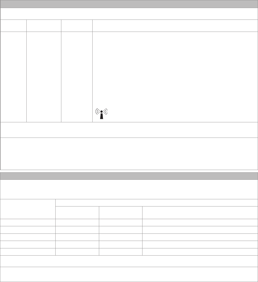
Interference may occur in the vicinity of equipment marked with the following symbol:
NOTE 1: At 80MHz and 800MHz, the higher frequency range applies�
NOTE 2: These guidelines may not apply in all situations� Electromagnetic propagation is aected by absorption and reection from structures, objects, and people�
(a) Field strengths from xed transmitters, such as base stations for radio (cellular/cordless) telephones and land mobile radios, amateur radio, AM and FM radio broadcast and
TV broadcast cannot be predicted theoretically with accuracy� To assess the electromagnetic environment due to xed RF transmitters, an electromagnetic site survey should be
considered� If the measured eld strength in the location in which the CROSSFLOW INTEGRATED ARTHROSCOPY PUMP system is used exceeds the applicable RF compliance level
above, the CROSSFLOW INTEGRATED ARTHROSCOPY PUMP system should be observed to verify normal operation� If abnormal performance is observed, additional measures
may be necessary, such as reorienting or relocating the CROSSFLOW INTEGRATED ARTHROSCOPY PUMP unit�
(b) Over the frequency range 150kHz to 80MHz, eld strengths should be less than 3V/m�
Recommended Separation Distances Between Portable and Mobile RF Communications Equipment and the CROSSFLOW INTEGRATED ARTHROSCOPY PUMP System
The CROSSFLOW INTEGRATED ARTHROSCOPY PUMP system is intended for use in an electromagnetic environment in which radiated RF disturbances are controlled� The user of
the CROSSFLOW INTEGRATED ARTHROSCOPY PUMP system can help prevent electromagnetic interference by maintaining a minimum distance between portable and mobile RF
communications equipment (transmitters) and the CROSSFLOW INTEGRATED ARTHROSCOPY PUMP system as recommended below, according to the maximum output power of
the communications equipment�
Rated maximum output power
(W) of transmitter
Separation distance (m) according to frequency of transmitter
150kHz to 80MHz
d = 1�2√P
80kHz to 800MHz
d = 1�2√P
800kHz to 2�5GHz
d = 2�3√P
0�01 0�12 0�12 0�23
0�1 0�38 0�38 0�73
1 1�2 1�2 2�3
10 3�8 3�8 7�3
100 12 12 23
For transmitters rated at a maximum output power not listed above, the recommended separation distance (d) in meters (m) can be estimated using the equation applicable to
the frequency of the transmitter, where P is the maximum output power rating of the transmitter in watts (W) according to the transmitter manufacturer�
NOTE 1: At 80MHz and 800MHz, the separation distance for the higher frequency range applies�
NOTE 2: These guidelines may not apply in all situations� Electromagnetic propagation is aected by absorption and reection from structures, objects, and people�
Regulatory Information
Federal Communications Commission (FCC)
FCC ID: SSH-XFLOW
Trade Name: CrossFlow Integrated Arthroscopy Pump
Type or Model: 0450000000
This device complies with Part 15 of the FCC rules� Operation is subject to the following two conditions:
• this device may not cause harmful interference, and
• this device must accept any interference received, including interference that may cause undesired
operation�
Note: FCC regulations provide that changes or modications not expressly approved by Stryker Endoscopy
could void your authority to operate this equipment�
EN-39
DRAFT
Frequency of transmission: 13�56MHz
Type of frequency / characteristics of the modulation: 10%ASK
Subcarrier: 423�75kHz, Manchester coding
Eective radiated power: 50µW
Industry Canada (IC)
IC: 4919C-XFLOW
Trade Name: CrossFlow Integrated Arthroscopy Pump
Type or Model: 0450000000
This device complies with Industy Canada license-exempt RSS standard(s)� Operation is subject to the
following two conditions: (1) this device may not cause interference, and (2) this device must accept any
interference, including interference that may cause undesired operation of the device�
The term “IC” before the radio certication number only signies that Industry Canada technical
specications were met�
R&TTE Declaration of Conformity
We, Name of company: Stryker Endoscopy
Address: 5900Optical Court, San Jose, CA 95138
Authorized representative: Jean-Yves Carentz
Contact detail of authorized representative: Stryker France, ZAC Satolas Green Pusignan, Av� de
Satolas Green, 69881 MEYZIEU Cedex, France
Declare under our sole responsibility that the product:
Product Name: CrossFlow Integrated Arthroscopy Pump
Trade Name: CrossFlow Integrated Arthroscopy Pump
Type or Model: 0450000000
Relevant Supplementary Information: None
to which this declaration relates is in conformity with the essential requirements and other relevant
requirements of the R&TTE Directive (1999/5/EC).
The product is compliant with the following standards and/or other normative documents:
Safety: EN 60601-1
EMC: EN 60601-1-2
Radio Spectrum: EN 300 330-1 V1�5�1
Supplementary information: none
Notied body involved: TÜV Rheinland Product Safety (GmbH)
Technical le held by: Stryker Endoscopy
Place and date of issue (of this DoC): San Jose, CA USA, DATE
Signed by or for the manufacturer:
Name: Mike Hilldoerfer
Title: Associate Director, Regulatory Aairs
Hereby, Stryker Endoscopy declares that this Short Range Device is in compliance with the essential
requirements and other relevant provisions of Directive 1999/5/EC�
EN-40
DRAFT
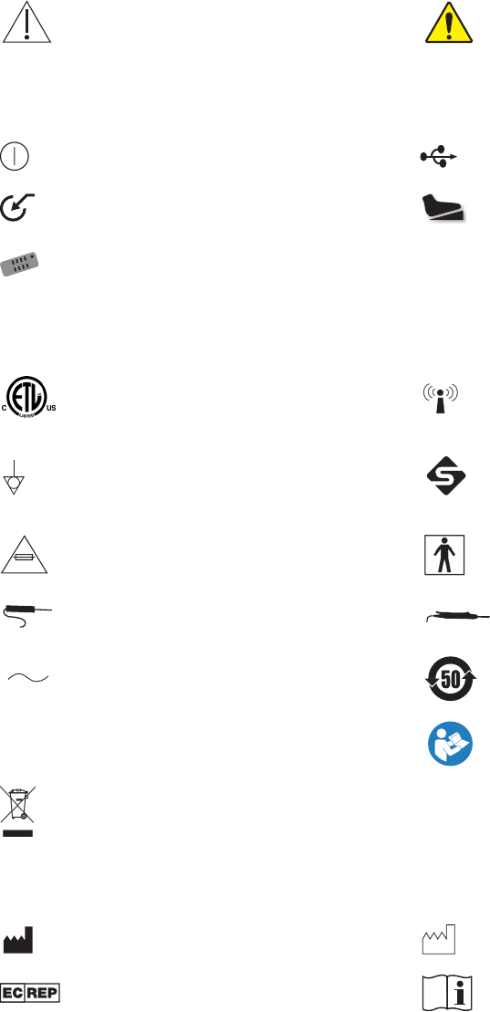
Symbols and Terminology
This device and its labeling contain symbols that provide important information for the safe and proper use
of the device� These symbols are dened below�
Warning
Warning/Caution: See Instructions for Use General warning sign, Multiple socket-outlet,
maximum allowed continuous output
Front Console
Power USB port
Auxiliary receptacle Footswitch receptacle
Hand control receptacle
Rear Console
Complies with CSA C22�2 No� 601�1, UL 60601-1 Emits RF radiation
Equipotential ground plug- connects to potential
equalization conductor� The resulting medical
electrical system shall follow all applicable IEC
60601-1 requirements�
Stryker Firewire- enables rewire connection
with Stryker rewire devices (Crossre, iSwitch,
SDC3)
Fuse rating Type BF Applied Part
Probe Shaver
Alternating Current RoHS 50years
IPX1 Protection against vertically falling objects Follow instructions for use
This product contains electrical waste or electronic equipment� It must not be disposed of as unsorted municipal
waste and must be collected separately�
Packaging/Labeling
Manufacturer Date of manufacture
Authorized representative in the European
community Consult instructions for use
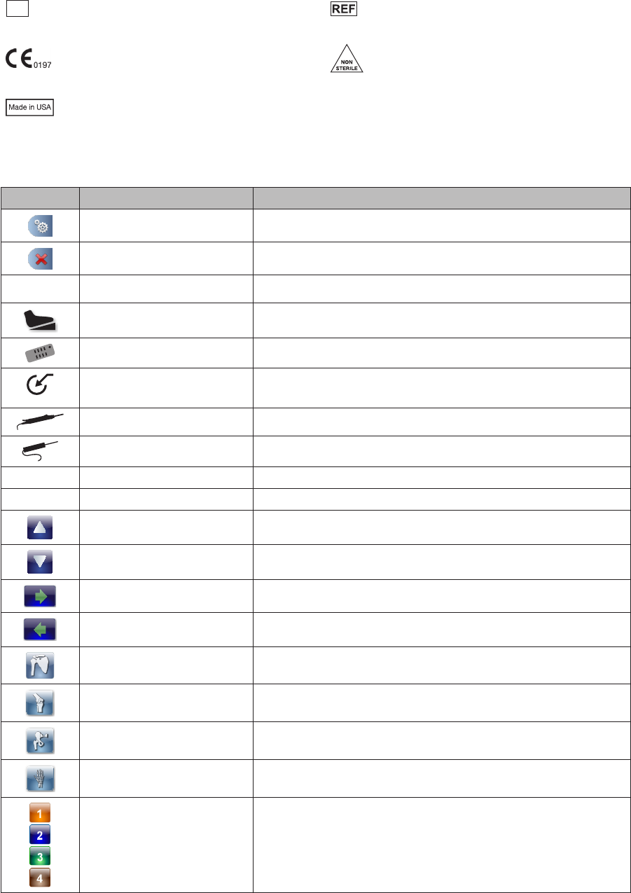
EN-41
DRAFT
SN Serial Number Catalog number
Fullls requirements of the European Medical
Device Directive 93/42/EEC Non-Sterile
Made in USA
Interface
Icon Name/Term Description
OPEN MAIN MENU Accesses the Main Menu
CLOSE MAIN MENU Closes the Main Menu
XF
CROSSFIRE Indicates the Crossre is attached
FOOTSWITCH Indicates the footswitch is attached
HAND CONTROL Indicates the hand control is attached
AUXILIARY DEVICE Indicates the auxiliary device is attached
(currently there are no approved auxiliary devices for use)
SHAVER Indicates an approved resection shaver console is attached
RF PROBE Indicates an approved resection RF console is attached
— OUTFLOW Indicates the Outow Cassette is inserted
DAY-USE
DAY-USE CASSETTE Indicates the Day-Use Cassette is inserted
UP Scrolls up
DOWN Scrolls down
FORWARD Advances to the next screen
BACK Returns to the previous screen
SHOULDER JOINT Selects the shoulder joint
KNEE JOINT Selects the knee joint
HIP JOINT Selects the hip joint
SMALL JOINT Selects the small joint
HARDWARE COMBINATION
SELECTION
Hardware combination selection (3 and 4 are only available if
the hip joint is selected)
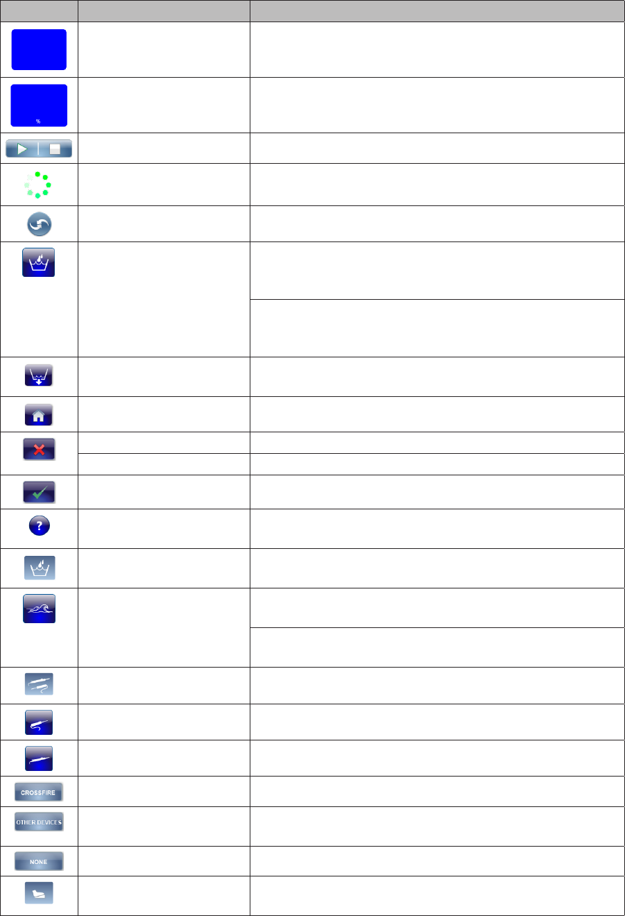
EN-42
DRAFT
Icon Name/Term Description
45
mmHg
PRESSURE Displays the current pressure setting
FLOW/SUCTION Displays the current ow/suction setting
START/STOP Starts/stops the pump
IN PROGRESS Indicates the pump is operating
HOT SWAP Toggles between hardware combination selections
WASH FUNCTION Increases the set pressure and ow limit by a user-specied
percentage over a user-specied duration (for Inow-only
mode)
Increases the set pressure and suction by a user-specied
percentage over a user-specied duration (for Inow/Outow
mode)
DRAIN FUNCTION Removes excess uid from the joint at the end of a case
(Outow mode only)
HOME Retuns to the user preference le selection screen
DELETE Deletes a le
CANCEL Rejects an action
CONFIRM Accepts an action
HELP Accesses task-oriented help related to screen and button
functionality
WASH MENU Navigates to the Wash menu to adjust the Wash and Clear
function settings
CLEAR FUNCTION Increases the ow limit by a user-specied percentage over a
user-specied duration (for Inow-only mode)
Increases the suction by a user-specied percentage over a
user-specied duration (for Inow/Outow mode)
RESECTION INTEGRATION Navigates to resection integration settings menu
RF PROBE Selects an approved resection RF console
SHAVER Selects an approved resection shaver console
CROSSFIRE Selects the Stryker Crossre console
APPROVED RESECTION
CONSOLE
Selects an approved resection console
NONE Indicates no RF/shaver console is selected
FOOTSWITCH/FORMULA
SHAVER OPTIONS
Programs footswitch and hand control options for Crossow,
iSwitch, Crossre, and Formula shaver

EN-43
DRAFT
Icon Name/Term Description
CROSSFLOW FOOTSWITCH Programs the settings for the CrossFlow footswitch
iSWITCH FOOTSWITCH Programs the settings for the iSwitch footswitch
CROSSFIRE FOOTSWITCH Programs the settings for the Crossre footswitch
FORMULA SHAVER� Programs the settings for the Formula Shaver
USER PREFERENCE Loads User Preference les
USB UPLOAD Uploads/saves user preference settings from/to USB drive
RIGHT ARROW Moves a le to the right screen
LEFT ARROW Moves a le to the left screen
SEND PREFERENCE FILE TO
CROSSFIRE
Sends a preference le to the Crossre system
SETTINGS Navigates to the Settings screens
GENERAL SETTINGS Adjusts the volume, brightness, and language
VOLUME Adjusts the volume of pump
BRIGHTNESS Adjusts the monitor brightness
SOFTWARE UPGRADE Loads new software upgrades from a USB drive
ACTUAL PRESSURE DISPLAY
ICON SELECTION
Selects the Actual Pressure Display icon
STRYKER SETTINGS Password-protected settings, for Stryker use only
— FLOW The uid entering and exiting the joint; keeps the joint space
clear by removing loose tissue, debris, and uid from the joint�
— FLOW LIMIT The maximum ow rate�
— FLOW RATE The speed at which uid enters and exits the joint; measured
as volume over time, or liters per minute (L/min)�
— PRIME To remove air from the inow tubing prior to pumping uid
through the tubing�
— SUCTION The force required to pull loose tissue, debris, and uid from
the joint�
EN-44
DRAFT
DRAFT

DRAFT
Stryker Endoscopy
5900 Optical Court
San Jose, CA 95138 USA
1-408-754-2000, 1-800-624-4422
www�stryker�com
European Representative
Regulatory Manager, Stryker France
ZAC Satolas Green Pusignan
Av� De Satolas Green
69881 MEYZIEU Cedex, France
Stryker Corporation or its divisions
or other corporate aliated entities
own, use or have applied for the
following trademarks or service marks:
CrossFlow and the Stryker logo. All
other trademarks are trademarks of
their respective owners or holders�
P17330 A
2012/06