Stryker Instruments 0400-615 Voice Communication System User Manual Steri Shield Comm
Stryker Instruments Voice Communication System Steri Shield Comm
Users Manual
DRAFT
1
Manufactured for:
Stryker Instruments
4100 E. Milham
Kalamazoo, MI 49001 (USA)
800-253-3210
269-323-7700
www.stryker.com
Wireless
Communication
System
8/05 400-615-701 Rev-
IMPORTANT INFORMATION: File in your maintenance records
DRAFT
2

DRAFT
3
Important Information
The words WARNING, CAUTION and NOTE carry special meanings and should be carefully
reviewed.
WARNING: The personal safety of the patient and/or user may be involved. Disregarding this
information could result in injury to the patient and/or operating room staff.
CAUTION: These instructions point out special service procedures or precautions that must
be followed to avoid damaging the device.
NOTE: This provides special information to make maintenance easier or important
instructions more clear.
This symbol is used to alert the reader to important safety and precautionary
information. When displayed on device, refers user to a accompanying
instructions and identifies safety and precautionary information.
Compliance Statements
Federal Communications Commission (FCC)
FCC ID: Q9R-0400-615
This equipment complies with Part 15 of the FCC rules. Operation is subject to the following
two conditions: (1) this equipment may not cause harmful interference, and (2) this device
must accept any interference received, including interference that may cause undesired
operation.
NOTE: FCC regulations provide that changes or modifications not expressly approved by
Stryker Instruments could void your authority to operate this equipment.
FCC Radiation Exposure Statement for Portable Devices
This equipment complies with FCC radiation exposure limits set forth for an uncontrolled
environment. This equipment is in direct contact with the body of the user under normal
operating conditions. This transmitter must not be co-located or operated in conjunction with
any other antenna or transmitter.
• Use of this system outside the US may be prohibited where it is subject to government
regulation.

DRAFT
4
Safety*
WARNINGS:
• Before using any system component or any component compatible with this system, read
and understand the instructions. Pay special attention to WARNING information. Become
familiar with system components prior to use.
• Upon initial receipt and before each use, operate system components and inspect for
damage. DO NOT use if damage is apparent. Perform recommended maintenance as
indicated in the instructions for use. Only trained and experienced professionals should
maintain this instrument.
• Use only Stryker approved accessories. Other accessories may result in increased
emission or decreased immunity of the system. Contact your Stryker sales
representative for a complete list of accessories. DO NOT modify any accessory.
• Equipment is not suitable for use in the presence of flammable anesthetic mixture with air,
oxygen or nitrous oxide.
• DO NOT use a radio while it is still charging. If additional power is needed, use the
supplemental battery provided in the extended life battery set. Failure to comply may
result in patient and/or operating room staff injury.
*For further information, contact your Stryker Instruments sales representative or Customer
Service at 1-800-253-3210.

DRAFT
5
Description
The Wireless Communication System may be used in conjunction with the Stryker Turbo 5
Communication Helmet. The Turbo 5 Communication Helmet is a component of the Personal
Protection System which is intended as a personal protection system to provide a barrier
between the operating environment and the members of the surgical team in order to help
protect against contamination and/or exposure to infectious body fluids and harmful
microorganisms.
The Wireless Communication System facilitates simultaneous communication between as
many as four people where communication may be compromised by ambient noise or
muffled by protective surgical gear. The system allows hands-free direct communication for
surgical team members within the operating room and for team members in different work
areas. To facilitate clarity, ambient noise is filtered by noise canceling microphones. Under
optimal conditions, transmission range extends to .125 mile.
The system requires a Digitally Matched Set of Radios which are provided with four AC
Charger/Adaptors and a Multiple Outlet Power Strip. Voice transmits through Turbo 5
Communication Helmets or Stand Alone Headsets. A Supplemental Battery is available with
the Extended Life Battery Set and may be used to double talking time.
Accessory Information
WARNING: Use only Stryker approved accessories. Contact your Stryker sales
representative for a complete list of accessories. DO NOT modify any accessory.
Failure to comply may result injury.
NOTE: See instructions for use suplied with Turbo 5 Communication Helmet for specific
instructions and information.
Turbo 5 Communication Helmet ................................................. 0400-615-000
Digitally Matched Set of Radios with Charging Accessories ... 0400-615-030
Stand Alone Headset ................................................................. 0400-615-640
Extended Life Battery Set ......................................................... 0400-615-375
Sony® Ear Phone - Right .......................................................... 0400-615-600
Sony® Ear Phone -Left ............................................................. 0400-615-610
Panasonic® Ear Phone - Right .................................................. 0400-615-620
Panasonic® Ear Phone - Left .................................................... 0400-615-630
NOTE: See instructions for use suplied with Turbo 5 Communication Helmet for specific
instructions and information.
Sony is a registered trademark of Sony Corporation.
Panasonic is a registered trade mark of Matsushita Industrial Electric Corp. LTD.
DRAFT
6
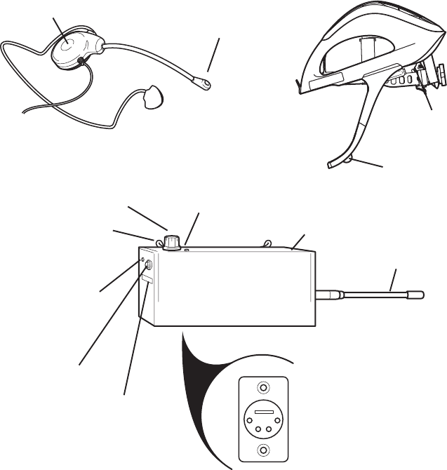
On/Off-Volume Dial
Charging
Jack
Power Indicator
Glows green when
radio is turned on and
battery is charged.
Belt Clip
Charge Indicator
Red light glows while
radio is charging or
operating with a
supplemental battery
pack
ID Code
Number
Radio Indentification
Indicates MASTER or
REMOTE radio
System Features and Functions
Audio
Jack
Antenna
Stand-alone Headset
Radio
NOTE: To communicate properly, all radios in the group must be components
of a matched set which are identified by a the same ID code number.
Communication Helmet
Microphone
Earphone
Jack
Earphone
Microphone
DRAFT
7
Instructions
Color Code Your Radios
NOTES:
• The radios in this set are digitally matched and must be
retained as a set. Color ID labels are provided so you can
color code each radio in the set with the same color labels
for quick reference.
• If your facility uses multiple sets of radios, select a unique
color to differentiate each set. If colors are duplicated,
write on the labels to further identify matched set.
1. Select one label set. For example, red.
2. Apply the label marked MASTER on the master
radio. Select the labels marked REMOTE from the
same label set and apply them to the remote
radios.
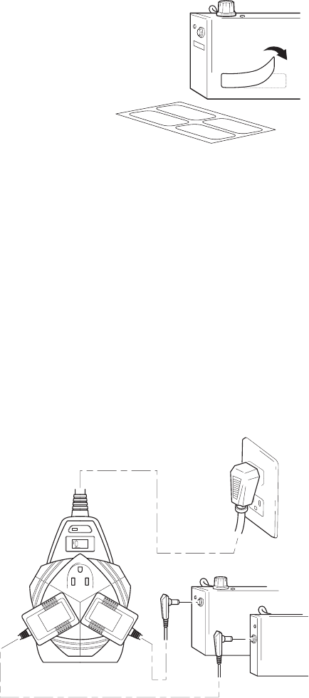
Charging the Radios and Supplemental Battery
CAUTIONS:
•Do not substitute the AC charger/adaptors or power strip
as damage may occur to the battery.
• Do not exceed 16 hours of charging time. For optimum
battery performance and life, do not leave a radio or
supplemental battery connected to the AC charger/adaptor
after reaching full charge.
NOTE: Radios must be turned off while charging.
1. Plug the power strip into an AC wall
outlet.
2. Turn the power strip on. The toggle
switch will illuminate.
3. Plug the AC charger/adaptors into
the power strip receptacles.
4. Ensure each radio is turned off.
5. Plug the AC charger/adaptor
connectors firmly into each
radio and/or supplemental
battery jack. The charge
indicator will illuminate to
indicate a charging
connection.
6. Allow radios and/or
supplemental batteries to
charge for a minimum of
12 hours.
DRAFT
8
Using the Radios
NOTES:
• Radios must fully charged before use.
•Radios must be from the same digitally matched set. A
matched set will have the same code number and color
code if you’ve opted to use the color code labels.
•The master radio must be turned on prior to turning on
the remote radios and remain in proximity to other
radios.
• Communication will be disrupted if the master radio is
turned off. Remote radios may be turned off and on
without disrupting other team members.
•Audio performance will become erratic with excessive
interference such as squeaking or buzzing if battery
power becomes too low.
• A supplemental battery may be used to prolong
communication. See instructions for Using a
Supplemental Battery.
1. Verify that each radio has the same ID number to
ensure a digitally matched set. Additionally, if color
code labels were used, they will facilitate quicker
identification of a digitally matched set.
2. Make sure each radio is turned off.
3. Put on the headsets/helmets. If using the Turbo 5
Communication Helmet, refer to instructions supplied
with the helmet. If using a stand-alone headset, adjust
the boom so that the microphone is approximately 1.0
inch away from the mouth.
4. Hang radios from the waistband on the left hip to
ensure free arm movement and convenient access to
the on/off/volume dial.
5. Plug the headset/helmet cable into each radio.
6. Initially turn on the master radio with the on/off-volume
dial keeping the volume low. The power indicator will
immediately illuminate. Wait 15 seconds then turn on
each remote radio.
7. Verify that communication is established by having
team members speak into their microphones. Adjust
the on/off-volume dial to set volume at a comfortable
level.
8. If using a helmet, put on the Steri-Shield togas or
hoods. Refer to instructions supplied with the togas
and hoods.
NOTE: Communication will be disrupted if the master radio
is turned off. To reestablish communication, turn each
radio off. Turn the master radio on again and wait 15
DRAFT
9
seconds then turn on each remote radio.
Communication will resume.
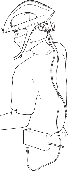
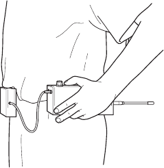
Using the Supplemental Battery Pack
1. Hang the supplemental battery form the waistband
as shown. Install the cable into the radio jack and
thread the collar to secure the connection. The
radio’s charge indicator will illuminate while the
supplemental battery is in use.

DRAFT
10
PROBLEM
AC charger/adaptor plug will
not fully insert into the
charger jack.
Charge indicator does not
illuminate when the adaptor/
charger is plugged into the
radio or supplemental
battery.
Static or interference.
Messages not transmitted.
CAUSE
Damaged component.
Power strip is turned off.
Charger not plugged in.
Charger defective.
Talk range has been
exceeded.
Low Battery
Master radio has been
turned off.
Radios are not from the
same matched set.
Master radio is out of range.
One or more batteries are
expended.
SOLUTION
Return to Stryker for repair.
Reset power strip toggle
switch.
Check electrical connections.
Return to Stryker for repair.
Keep team members within
operating range.
Recharge battery or use
supplemental battery.
Turn all radios off. Turn
master radio on. Wait 15
seconds then turn on remote
radios.
Confirm radios have the
same code
Make sure is in proximity to
other radios.
Use supplemental battery or
recharge batteries.
Troubleshooting Guidelines
This product is not field repairable. In case of operating difficulties, return this product to Stryker Instruments for repair. For more
information, contact your Stryker sales representative or call Stryker Customer Service at 1-800-253-3210.

DRAFT
11
Cleaning Recommendations
CAUTIONS:
• Do not immerse.
• Do not autoclave.
• Do not use alcohol or harsh cleansers as they can damage the casing and leak inside and
cause permanent damage.
1. Turn radios off.
2. Detach radios from helmets and/or headsets.
3. Use a soft cloth dampened in water and a mild detergent to clean the exterior surface of the
radios and supplemental batteries.
4. Jacks may be wiped with a dry, lint-free cloth.
Disposal
The radio and supplemental battery contain Nickel Metal Hydride. Check with your local
enviromental protection agency for special disposal restrictions.
Specifications are approximate and may vary slightly from unit to unit.
This device is not field repairable.
Specifications
Model Master and Remote Radios
Size: 2.5 in. [6.4 cm] height
5.1 in. [12.9 cm] width
2.5 [6.4 cm] deep
Weight: 14 oz. [0.4 Kg]
Modulation: FM
Frequency Range: 902-928 MHz with over 256,000 codes
Tuning: Auto tuning
Power: 6 V NiMH rechargeable battery
Battery Life: 2200 mAh, 6-8 hours
FCC License: Part 15, no license required
Transmit Power: 300 mV/m
Intermediate Frequency
Bandwidth: <500 KHz
Antenna: 1/4 wave helical
Operating Range: .125 mile or 201 m (line of sight)
Temperature Range: -40° C to + 80°C
Audio Connector: 4 conductor XLR Type (chassis mount)
Microphone Types: Noise cancelling electret microphone
Model Supplemental Battery
Size: 2.4 in. [6.1 cm] height
4.4 in. [11.2 cm] width
1.2 in. [3 cm] deep
Weight: 12.4 oz. [0.35Kg]
Power: 6 V NiMH rechargeable battery
Battery Life: 2200 mAh, 6-8 hours
Temperature Range: -40° C to + 80°C
DRAFT
12